JP5801657B2 - Liquid pouring tool - Google Patents

Liquid pouring tool Download PDF

Info

Publication number
JP5801657B2
JP5801657B2 JP2011191810A JP2011191810A JP5801657B2 JP 5801657 B2 JP5801657 B2 JP 5801657B2 JP 2011191810 A JP2011191810 A JP 2011191810A JP 2011191810 A JP2011191810 A JP 2011191810A JP 5801657 B2 JP5801657 B2 JP 5801657B2
Authority
JP
Japan
Prior art keywords
liquid
bottle
air
air passage
seal
Prior art date
Legal status (The legal status is an assumption and is not a legal conclusion. Google has not performed a legal analysis and makes no representation as to the accuracy of the status listed.)
Active
Application number
JP2011191810A
Other languages
Japanese (ja)
Other versions
JP2013052897A (en
Inventor
一芳 名取
一芳 名取
詩子 白藤
詩子 白藤
Original Assignee
株式会社サントリー・ショッピング・クラブ
株式会社日出商事
Priority date (The priority date is an assumption and is not a legal conclusion. Google has not performed a legal analysis and makes no representation as to the accuracy of the date listed.)
Filing date
Publication date
Application filed by 株式会社サントリー・ショッピング・クラブ, 株式会社日出商事 filed Critical 株式会社サントリー・ショッピング・クラブ
Priority to JP2011191810A priority Critical patent/JP5801657B2/en
Publication of JP2013052897A publication Critical patent/JP2013052897A/en
Application granted granted Critical
Publication of JP5801657B2 publication Critical patent/JP5801657B2/en
Active legal-status Critical Current
Anticipated expiration legal-status Critical

Links

Images

Landscapes

  • Closures For Containers (AREA)

Description

本発明は、液体注出具に係り、特に、ボトルの口に装着されてボトル内の液体を一定量注出するための液体注出具に関する。   The present invention relates to a liquid dispenser, and more particularly, to a liquid dispenser that is attached to a mouth of a bottle to dispense a certain amount of liquid in the bottle.

従来から、ボトルの口に装着されて、ボトル内の液体を一定量注出するための液体注出具が提供されている。この液体注出具は、例えば酒類などのボトルに装着され、カクテルなどを作る際に、グラスやメジャーカップなどへ所定量のお酒を注ぐためのものである。   2. Description of the Related Art Conventionally, there has been provided a liquid dispenser that is attached to the mouth of a bottle to dispense a certain amount of liquid in the bottle. This liquid pouring tool is attached to, for example, a bottle of liquor, and is used to pour a predetermined amount of liquor into a glass or a major cup when making a cocktail or the like.

図6は、従来の液体注出具101を示す図であり、図6(A)は平面図を示し、図6(B)は図6(A)のB−B線における断面図を示している。これらの図に示すように、従来の液体注出具101は、管状の注出部111と、この注出部111と連通する管状の計量部121と、この計量部121に沿って配置されてボトルの外部から内部へ空気を通すための空気通路131,141とを備え、空気通路131,141は略一直線状に形成されている。   FIG. 6 is a view showing a conventional liquid dispensing tool 101, FIG. 6 (A) shows a plan view, and FIG. 6 (B) shows a cross-sectional view taken along line BB in FIG. 6 (A). . As shown in these drawings, a conventional liquid pouring tool 101 includes a tubular pouring portion 111, a tubular measuring portion 121 communicating with the pouring portion 111, and a bottle disposed along the measuring portion 121. Air passages 131 and 141 for passing air from the outside to the inside, and the air passages 131 and 141 are formed in a substantially straight line.

空気通路131,141は、ボトル内の液体を外部に注出する際に、ボトル内に空気を通すためのものであり、計量部121に沿って延設されている。実際の使用態様においては、ボトルを逆さまにすることにより、計量部121内に液体が充填されると共に、注出部111から液体が注出される。そのとき、注出される液体と入れ替わる形で空気がボトル内に導入されるのである。   The air passages 131 and 141 are for passing air into the bottle when the liquid in the bottle is poured out, and extend along the measuring unit 121. In an actual usage mode, by turning the bottle upside down, the liquid is filled into the measuring unit 121 and the liquid is poured out from the pouring unit 111. At that time, air is introduced into the bottle in a form that replaces the liquid to be dispensed.

上記従来の液体注出具101においては、空気通路131,141が一直線状に形成されており、その断面も全長にわたってほぼ一定であった。また、空気通路131,141のボトル側の開口部148の近傍も、何ら構造的な工夫も施されていなかった。このため、ボトルを逆さまにする際に、ボトル内の液体が空気通路131,141のボトル側開口部148内に入り込み、場合によっては注出部側の開口部111cに漏洩してしまう場合もあった。このような液体の漏洩が発生した場合には、抽出すべき一定量以上の液体が出てしまい抽出量が一定しなかったり、また注出部111を清浄に保つための作業が必要になっていた。   In the conventional liquid pouring tool 101, the air passages 131 and 141 are formed in a straight line, and the cross section thereof is substantially constant over the entire length. Also, no structural device has been applied to the vicinity of the opening 148 on the bottle side of the air passages 131 and 141. For this reason, when the bottle is turned upside down, the liquid in the bottle may enter the bottle side opening 148 of the air passages 131 and 141 and may leak into the opening 111c on the outlet side in some cases. It was. When such a liquid leakage occurs, a certain amount or more of liquid to be extracted comes out, and the amount of extraction is not constant, or work for keeping the dispensing part 111 clean is necessary. It was.

本発明は、上記課題に鑑みてなされたものであって、空気通路の注出部側の開口部からの液体の漏洩を防止することができる、新規な液体注出具を提供することをその目的とする。   The present invention has been made in view of the above problems, and an object of the present invention is to provide a novel liquid dispensing tool that can prevent leakage of liquid from the opening on the dispensing portion side of the air passage. And

上記課題を解決するために、ボトルの口に装着されて、ボトル内の液体を一定量注出するための液体注出具であって、ボトルの外部へ抽出する液体を計量して注出する管状の計量抽出部と、ボトルの外部から内部へ空気を通すための空気通路とを備え、前記空気通路はその内部の空気の流れが屈折又は変曲するように形成されていると共に、前記空気通路の途中には当該空気通路の断面積よりも大きな断面積を有する空気溜まりが形成されている、という構成を採っている。   In order to solve the above-mentioned problem, it is a liquid pouring tool that is attached to the mouth of a bottle to pour out a certain amount of liquid in the bottle, and is a tube that measures and pours the liquid to be extracted to the outside of the bottle And an air passage for passing air from the outside to the inside of the bottle, wherein the air passage is formed so that the flow of air in the inside is refracted or bent, and the air passage In the middle, the air reservoir having a cross-sectional area larger than the cross-sectional area of the air passage is formed.

また、前記計量抽出部は、ボトル内から注出した液体を計量する計量部と、該計量部に連通され液体をボトルの外部へ注出する注出部とからなり、
前記空気通路は、前記計量部に沿って配置されている、という構成を採っている。
The metering extraction unit includes a metering unit for metering the liquid dispensed from the bottle, and a dispensing unit communicating with the metering unit for dispensing the liquid to the outside of the bottle.
The said air passage has taken the structure that it is arrange | positioned along the said measurement part.

また、前記空気溜まりは、前記空気通路内の空気の流れが屈折又は変曲する位置のうち少なくとも1箇所に配されていることを特徴とする、請求項1又は2に記載の液体注出具。   3. The liquid dispensing tool according to claim 1, wherein the air reservoir is disposed in at least one of positions where the air flow in the air passage is refracted or bent.

また、前記空気溜まりは、前記空気通路におけるボトル側の末端部に設けられている、という構成を採っている。   Moreover, the said air reservoir is taken as the structure provided in the terminal part by the side of the bottle in the said air path.

また、前記空気通路は、前記計量部に沿って略直線状に形成されており、空気通路のボトル側の開口部は前記計量部における空気通路の延長線上からずれた位置に設けられている、という構成を採っている。   Further, the air passage is formed substantially linearly along the measuring portion, and the opening on the bottle side of the air passage is provided at a position shifted from the extension line of the air passage in the measuring portion, The structure is adopted.

また、前記計量部の外周部には、ボトルへの固定及び液体のボトル外への漏洩を防止するための密封部材が装着されている、という構成を採っている。   Further, a configuration is adopted in which a sealing member is attached to the outer peripheral portion of the measuring portion for fixing to the bottle and preventing leakage of the liquid to the outside of the bottle.

また、前記密封部材の外周面には、大きさの異なる複数の環状シールが形成されており、前記注出部に近い側に、最も直径の大きな環状の第1シールが設けられている、という構成を採っている。   Further, a plurality of annular seals having different sizes are formed on the outer peripheral surface of the sealing member, and an annular first seal having the largest diameter is provided on the side close to the extraction portion. The composition is taken.

また、前記第1シールのボトル側には、第1シールから離れて少なくとも1つの環状の第2シールが設けられている、という構成を採っている。   Further, the bottle side of the first seal is provided with at least one annular second seal away from the first seal.

また、前記第2のシールは4つ設けられている、という構成を採っている。   In addition, four second seals are provided.

また、前記第1シール及び少なくとも2つの第2シールとは、不等間隔に配置されている、という構成を採っている。   Further, the first seal and the at least two second seals are arranged at unequal intervals.

また、前記第1シールの直径は23mmであり、前記第2シールの直径は21mmである、という構成を採っている。   Further, the first seal has a diameter of 23 mm, and the second seal has a diameter of 21 mm.

更に、前記第1シールと第2シールとの間隔は5.5mmであり、隣接する複数の第2シール同士の間隔は3mmまたは3.5mmである、という構成を採っている。   Furthermore, the interval between the first seal and the second seal is 5.5 mm, and the interval between a plurality of adjacent second seals is 3 mm or 3.5 mm.

本願発明の液体注出具を示す図であり、図1(A)は平面図を示し、図1(B)は図1(A)のB−B線における断面図を示す。It is a figure which shows the liquid extraction tool of this invention, FIG. 1 (A) shows a top view, FIG.1 (B) shows sectional drawing in the BB line of FIG. 1 (A). 図1に開示された液体注出具に装着される密封部材を示す図であり、図2(A)は平面図を示し、図2(B)は図2(A)のB−B線における断面図を示す。It is a figure which shows the sealing member with which the liquid extraction tool disclosed by FIG. 1 is mounted | worn, FIG. 2 (A) shows a top view, FIG.2 (B) is a cross section in the BB line of FIG. 2 (A). The figure is shown. 図2の密封部材が装着された液体注出具を示す図であり、図3(A)は斜視図を示し、図3(B)は密封部材のみを断面図とした側面図を示す。It is a figure which shows the liquid extraction tool with which the sealing member of FIG. 2 was mounted | worn, FIG. 3 (A) shows a perspective view, FIG.3 (B) shows the side view which made only the sealing member sectional drawing. 図3に開示した液体注出具をボトルに装着した状態を示す断面図である。It is sectional drawing which shows the state which mounted | wore the bottle with the liquid extraction tool disclosed in FIG. 液体注出具の作用を説明するための断面図であり、図5(A)は注出前の状態を示し、図5(B)は注出初期の状態を示し、図5(C)は注出中の状態を示す、図5(D)は注出終期および注出停止状態を、それぞれ示している。It is sectional drawing for demonstrating the effect | action of a liquid pouring tool, FIG. 5 (A) shows the state before pouring, FIG. 5 (B) shows the state at the initial stage of pouring, and FIG. 5 (C) is pouring. FIG. 5 (D) showing the inside state shows the end of pouring and the pouring stop state, respectively. 従来の液体注出具を示す図であり、図6(A)は平面図を示し、図6(B)は図6(A)のB−B線における断面図を示す。It is a figure which shows the conventional liquid extraction tool, FIG. 6 (A) shows a top view, FIG.6 (B) shows sectional drawing in the BB line of FIG. 6 (A).

以下に、図面を参照しながら、本願発明の一実施形態について説明する。   Hereinafter, an embodiment of the present invention will be described with reference to the drawings.

[全体概要]
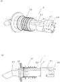
先ず、図1は、本願発明の一実施形態に係る液体注出具1を示す図であり、図1(A)は平面図を示し、図1(B)は図1(A)のB−B線における断面図を示す。この図に示すように、液体注出具1は、ボトル(図示略)の口に装着されてボトル内の液体を一定量注出するためのものであって、管状の注出部11と、この注出部11と連通する管状の計量部21と、この計量部21に沿って配置されてボトルの外部から内部へ空気を通すための空気通路31とを備え、前記空気通路31の途中に空気溜まり42が形成されている。なお、ここでいうボトルについてはその素材や大きさについて特に限定されるものではなく、PETボトルであっても瓶容器であっても、口がある容器であればかまわない。また、管状とは、液体あるいは気体が通れるよう内部が中空になっていれば、その外形の形状については特に限定されない、例えば、断面の外形が円形でも四角形でもかまわない。以下、各部について説明する。
[Overview]
First, FIG. 1 is a figure which shows the liquid extraction tool 1 which concerns on one Embodiment of this invention, FIG. 1 (A) shows a top view, FIG.1 (B) is BB of FIG. 1 (A). A cross-sectional view along the line is shown. As shown in this figure, the liquid dispenser 1 is attached to the mouth of a bottle (not shown) to dispense a fixed amount of liquid in the bottle. A tubular measuring unit 21 communicating with the dispensing unit 11 and an air passage 31 arranged along the measuring unit 21 for allowing air to pass from the outside to the inside of the bottle are provided. A reservoir 42 is formed. In addition, about the bottle here, it does not specifically limit about the raw material and magnitude | size, Even if it is a PET bottle and a bottle container, it may be a container with a mouth. In addition, the shape of the outer shape of the tube is not particularly limited as long as the inside is hollow so that liquid or gas can pass therethrough. For example, the outer shape of the cross section may be circular or square. Hereinafter, each part will be described.

[注出部]
注出部11は、液体注出具1がボトルに装着された場合に、ボトルの外部側に露出する部分である。具体的には、グラスやメジャーカップなどへ液体(例えば、酒類)を注出するための注ぎ口となっている。注出部11は管状の部材から形成されており、内部に液体が通る内腔13が形成されている。本実施形態の注出部11は、後述する計量部21の軸線と平行な根元部11aと、この根元部11aに対して略25°傾斜した先端部11bとからなる。先端部11bを傾斜させているのは、使用者が液体を注出する際の使い勝手を考慮したためである。また、先端部11bの注ぎ口は斜めにカットされているが、これは注ぎ口での液だれを防止するためである。但し、当該構造や先端部11bの傾斜角度はあくまでも一例であり、より小さな傾斜角或いは大きな傾斜角にしても良いし、傾斜させずに一直線状に形成しても良い。また、円弧状に湾曲させて、注ぎ口の部分に所定の傾斜角が生じるように構成してもよい。
[Pouring section]
The pouring part 11 is a part exposed to the outside of the bottle when the liquid pouring tool 1 is attached to the bottle. Specifically, it serves as a spout for pouring liquid (eg, liquor) into a glass or a major cup. The dispensing part 11 is formed from a tubular member, and has a lumen 13 through which liquid passes. The pouring part 11 of the present embodiment includes a base part 11a parallel to the axis of the measuring part 21 described later, and a tip part 11b inclined by approximately 25 ° with respect to the base part 11a. The reason why the tip 11b is inclined is because the user-friendliness when the user pours out the liquid is taken into consideration. Further, the spout of the tip portion 11b is cut obliquely in order to prevent dripping at the spout. However, the inclination angle of the structure and the tip end portion 11b is merely an example, and may be a smaller inclination angle or a larger inclination angle, or may be formed in a straight line without being inclined. Further, it may be configured to be curved in an arc shape so that a predetermined inclination angle is generated at the spout portion.

また、液体注出具1の根元部11aには、環状鍔部15が形成されている。この環状鍔部15は、後述する密封部材51が当接する部分である。なお、本実施形態の注出部11は、液体注出具1の他の部分と一体的に構成されている。しかしながら、本発明はこれに限定されるものではなく、注出部11を計量部21と別体で構成し、接着やネジ止めなどで結合するような構造としてもよい。但し、液漏れなどの対策のために、結合部にはオーリングなどを装着することが望ましい。また、本実施形態の液体注出具1の材質はプラスチックであるが、金属などで形成してもよい。   In addition, an annular flange 15 is formed on the root portion 11 a of the liquid pouring tool 1. The annular flange 15 is a portion with which a sealing member 51 described later comes into contact. In addition, the extraction | pouring part 11 of this embodiment is comprised integrally with the other part of the liquid extraction tool 1. FIG. However, the present invention is not limited to this, and the dispensing unit 11 may be configured separately from the measuring unit 21 and may be coupled by bonding or screwing. However, it is desirable to attach an O-ring or the like to the coupling portion for countermeasures such as liquid leakage. Moreover, although the material of the liquid extraction tool 1 of this embodiment is a plastic, you may form it with a metal etc.

[計量部]
計量部21は、上記環状鍔部15を境として、注出部11と連通する管状の部材から形成されている。この計量部21は、注出部11の根元部11aと略一直線状に位置しており、内部に断面円形の内部空間23が形成されている。また、計量部21における注出部11に近い側の側壁には、矩形の液体通過穴25が設けられている。この液体通過穴25は、ボトル内の液体を計量部21の内部空間23に導入するためのものであり、本実施形態では2つ設けられている。但し、液体通過穴25の数や形状は一例であって、円形や楕円形の形状を採用しても良いし、数も1つでも良いし3つ以上でもよい。また、計量部21の側壁の円周方向に沿って細いスリットを多数形成するような構造であってもよい。
[Weighing unit]
The measuring portion 21 is formed of a tubular member that communicates with the extraction portion 11 with the annular flange 15 as a boundary. The measuring portion 21 is positioned substantially in a straight line with the base portion 11a of the extraction portion 11, and an internal space 23 having a circular cross section is formed therein. In addition, a rectangular liquid passage hole 25 is provided on the side wall of the measuring unit 21 on the side close to the dispensing unit 11. The liquid passage hole 25 is for introducing the liquid in the bottle into the internal space 23 of the measuring unit 21. In the present embodiment, two liquid passage holes 25 are provided. However, the number and shape of the liquid passage holes 25 are merely examples, and a circular or elliptical shape may be adopted, or the number may be one or three or more. Moreover, the structure which forms many thin slits along the circumferential direction of the side wall of the measurement part 21 may be sufficient.

計量部21の内部空間23内には、所定の第1金属球27が移動自在に配置されている。計量部21の内部空間23における注出部11側の一端部は、第1金属球27の直径よりも小さな直径を有する第1弁座部29となっている。この第1弁座部29は、注出部11から計量部21に向かって直径が拡大するようなテーパー面となっており、第1金属球27が当接することで、計量部21から注出部11への液体の流れを停止させることができるようになっている。このため、本実施形態では、注出部11の内腔13が第1金属球27の直径より小さな直径を有すると共に、その内腔13と計量部21の内部空間23との遷移領域が第1弁座部29として形成されている。但し、計量部21の内部空間23の一端部に第1弁座部29が形成されていればよいので、必ずしも注出部11の内腔13の全体が第1金属球27の直径より小さな直径を有している必要は無い。   A predetermined first metal ball 27 is movably disposed in the internal space 23 of the measuring unit 21. One end of the measuring portion 21 on the side of the extraction portion 11 in the internal space 23 is a first valve seat portion 29 having a diameter smaller than the diameter of the first metal ball 27. The first valve seat portion 29 has a tapered surface whose diameter increases from the pouring portion 11 toward the measuring portion 21, and is poured out from the measuring portion 21 when the first metal ball 27 comes into contact therewith. The liquid flow to the part 11 can be stopped. For this reason, in this embodiment, the lumen 13 of the extraction portion 11 has a diameter smaller than the diameter of the first metal sphere 27, and the transition region between the lumen 13 and the internal space 23 of the measuring portion 21 is the first. It is formed as a valve seat portion 29. However, since the first valve seat portion 29 only needs to be formed at one end portion of the internal space 23 of the measuring portion 21, the diameter of the entire lumen 13 of the extraction portion 11 is not necessarily smaller than the diameter of the first metal ball 27. It is not necessary to have.

また、計量部21の外周面には環状突起28が形成されている。この環状突起28は、後述する密封部材51を固定するためのものである。ここで、密封部材51は、計量部21側から環状突起28に向かってスライドさせて装着されるので、環状突起28の計量部21側の面は傾斜面あるいは曲面となっている。但し、これは必須な要件では無く、単純な板状の断面形状であってもよい。   An annular protrusion 28 is formed on the outer peripheral surface of the measuring portion 21. The annular protrusion 28 is for fixing a sealing member 51 described later. Here, since the sealing member 51 is slid from the measuring portion 21 toward the annular protrusion 28, the surface of the annular protrusion 28 on the measuring portion 21 side is an inclined surface or a curved surface. However, this is not an essential requirement, and a simple plate-like cross-sectional shape may be used.

また、計量部21の他端部には、蓋部材40が装着されている。この蓋部材40は、計量部21の内部空間23内の第1金属球27が外に出ないようにする機能と、本発明の特徴部分である空気溜まり42を形成する役割を有しているものである。また、計量部21の内部空間23内へ液体を供給するための機能も有しており、そのために内部に連通路43が形成されている。連通路43の他端側(図1における右方)には、連通路43の直径よりも大きな直径の第2金属球47が配置されており、この第2金属球47が連通路43の第2弁座部45に当接することにより、連通路43への液体の進入を停止できるようになっている。なお、第2金属球47は、蓋部材40内で僅かに移動できるようになっており、第2金属球47を取り囲む保持突起46によって外部に脱落しないようになっている。   A lid member 40 is attached to the other end portion of the measuring unit 21. The lid member 40 has a function of preventing the first metal ball 27 in the internal space 23 of the measuring unit 21 from going out and a role of forming an air reservoir 42 that is a characteristic part of the present invention. Is. Moreover, it has the function for supplying the liquid in the internal space 23 of the measurement part 21, and the communicating path 43 is formed in the inside for it. A second metal ball 47 having a diameter larger than the diameter of the communication path 43 is disposed on the other end side (right side in FIG. 1) of the communication path 43. By abutting the two-valve seat portion 45, the entry of liquid into the communication passage 43 can be stopped. The second metal sphere 47 can move slightly within the lid member 40, and is prevented from falling outside by the holding projection 46 surrounding the second metal sphere 47.

[空気通路]
次に、空気通路31、41について説明する。空気通路31は、環状鍔部15近傍から計量部21の他端部まで到達する管状の通路である。本実施形態では、計量部21の外周面に、計量部21の長手方向軸線と平行に設けられている。計量部21に沿った部位での空気通路31の内径は一定であり、略一直線状となっている。注出部11側の開口部11cは、環状鍔部15の表面近傍に開口している。また、蓋部材40内にも、空気通路41が形成されているが、この蓋部材40内の空気通路41は本実施形態の特徴部分であるので、以下に詳しく説明する。
[Air passage]
Next, the air passages 31 and 41 will be described. The air passage 31 is a tubular passage that reaches from the vicinity of the annular flange 15 to the other end of the measuring portion 21. In the present embodiment, the measuring unit 21 is provided on the outer peripheral surface of the measuring unit 21 in parallel with the longitudinal axis of the measuring unit 21. The inner diameter of the air passage 31 at the site along the measuring portion 21 is constant and is substantially straight. The opening part 11 c on the side of the extraction part 11 is open near the surface of the annular flange 15. An air passage 41 is also formed in the lid member 40. The air passage 41 in the lid member 40 is a characteristic part of this embodiment, and will be described in detail below.

蓋部材40内の空気通路41は、上述した連通路43とは別の通路として、計量部21の空気通路31と接続されている。本実施形態では、計量部21の空気通路31よりも直径が大きな空気通路として示されているが、直径の大きさは特に限定されるものではない。また、蓋部材40内の空気通路41の終端部には、空気溜まり42が形成されている。この空気溜まり42は、空気通路41よりも大きな断面積を有する所定の空間である。本実施形態では、蓋部材40内の空気通路41の直径の約3倍程度の断面積を有する空間となっている。但し、空気溜まり42の大きさは特に限定されるものではなく、空気通路41の断面積よりも大きな断面積を有する空間であればよい。   The air passage 41 in the lid member 40 is connected to the air passage 31 of the measuring unit 21 as a passage different from the communication passage 43 described above. In the present embodiment, the air passage is shown as an air passage having a diameter larger than that of the air passage 31 of the measuring unit 21, but the size of the diameter is not particularly limited. In addition, an air reservoir 42 is formed at the end portion of the air passage 41 in the lid member 40. The air reservoir 42 is a predetermined space having a larger cross-sectional area than the air passage 41. In the present embodiment, the space has a cross-sectional area of about three times the diameter of the air passage 41 in the lid member 40. However, the size of the air reservoir 42 is not particularly limited as long as the space has a cross-sectional area larger than the cross-sectional area of the air passage 41.

また、空気溜まり42の他端部にはボトル側の開口部48が形成されている。このボトル側の開口部48は、液体の注出中にボトル内に外部の空気を通すためのものであり、注出中は原則的に液体内に水没する状態となる。尚、ボトル側開口部48の大きさは特に限定されるものではないが、空気通路31,41内の液体の逆流を効果的に防ぐために、空気通路31,41の直径よりも小さな直径とすることが望ましい。また、ボトル側の開口部48は、計量部21の空気通路31の延長線上からはずれた位置に設けられている(図3(A)参照)。これは、後述するように、液体の逆流をより防止するための工夫である。   A bottle side opening 48 is formed at the other end of the air reservoir 42. The opening 48 on the bottle side is for allowing external air to pass through the bottle during the extraction of the liquid, and in principle, the bottle 48 is submerged in the liquid during the extraction. In addition, although the magnitude | size of the bottle side opening part 48 is not specifically limited, In order to prevent the backflow of the liquid in the air passages 31 and 41 effectively, it is set as a diameter smaller than the diameter of the air passages 31 and 41. It is desirable. Further, the opening 48 on the bottle side is provided at a position deviated from the extension line of the air passage 31 of the measuring unit 21 (see FIG. 3A). As will be described later, this is a device for further preventing the back flow of the liquid.

このように空気が溜まる空間があり、かつ、空気通路31、41内の空気の流れが一直線でなければ、空気溜まり42やボトル側開口部48の形状、配置は特に限定されない。例えば、空気溜まりは計量部21の全周を囲むように形成されていても、その一部に配置されるように形成されていてもかまわず、また、計量部21軸方向に対して蛇行したような形状で計量部21周面に形成されていてもかまわない。さらに、空気溜まり42の位置も、ボトル側端面は金型形成上都合が良いが、空気が溜まるのであれば計量部21軸方向中央付近でもかまわない。これにより、ボトルから液体を抽出すると同時にボトル内に流入する空気が、空気溜まり42にしっかり溜まると共に、空気通路31,41が一直線でないので空気通路31,41内で空気がぶつかり空気の流れに適度な乱れが生じることで、しっかりと空気抵抗を生じさせながら、ボトルから液体を抽出することができる。これにより、液体をボトルから一定量抽出後の漏洩を防止できる。   As long as there is a space for storing air and the flow of air in the air passages 31 and 41 is not a straight line, the shape and arrangement of the air reservoir 42 and the bottle side opening 48 are not particularly limited. For example, the air reservoir may be formed so as to surround the entire circumference of the measuring unit 21 or may be formed so as to be disposed in a part of the measuring unit 21, or meandered with respect to the axial direction of the measuring unit 21. It may be formed on the circumferential surface of the measuring portion 21 in such a shape. Furthermore, the position of the air reservoir 42 is also convenient for forming the mold on the bottle side end surface, but it may be near the center of the measuring unit 21 in the axial direction as long as air accumulates. As a result, the air flowing into the bottle at the same time as the liquid is extracted from the bottle is firmly retained in the air reservoir 42, and the air passages 31 and 41 are not in a straight line. As a result, the liquid can be extracted from the bottle while firmly generating air resistance. Thereby, leakage after extracting a certain amount of liquid from the bottle can be prevented.

[密封部材]
図2は、密封部材51を示す図である。密封部材51は計量部21の外周面に装着され、ボトル内の液体の漏洩を防止するためのものである。密封部材51は、略円筒状の密封部材本体51aと、この密封部材本体51aの一端部に一体的に設けられるフランジ部51bとを備えている。フランジ部51bの一端部側表面には、所定の円形凹部52が形成されており、この円形凹部52に注出部11の環状鍔部15の一部分を受け入れるようになっている。
[Sealing member]
FIG. 2 is a view showing the sealing member 51. The sealing member 51 is attached to the outer peripheral surface of the measuring unit 21 to prevent leakage of liquid in the bottle. The sealing member 51 includes a substantially cylindrical sealing member main body 51a and a flange portion 51b provided integrally with one end of the sealing member main body 51a. A predetermined circular recess 52 is formed on the one end side surface of the flange 51 b, and a part of the annular flange 15 of the extraction portion 11 is received in the circular recess 52.

また、密封部材本体51aの内部には、基本的に計量部21の外周輪郭と相補する関係の空間が形成されている。具体的には、計量部21の環状突起28に対応した環状凹部53が形成されている。但し、計量部21の外周面と密封部材51の内周面との間の隙間は、計量部21の液体通過穴25に液体を通過させる役割を有するため、密封部材51の内部空間の直径は、計量部21の外周面の直径よりも大きなものとして構成されている。特に、密封部材51の他端部側(図2における右方)の内径は、一端部側(図2における左方)の内径よりも大きなものとなっている。   Further, in the inside of the sealing member main body 51a, a space that is basically complementary to the outer peripheral contour of the measuring portion 21 is formed. Specifically, an annular recess 53 corresponding to the annular protrusion 28 of the measuring unit 21 is formed. However, since the gap between the outer peripheral surface of the measuring unit 21 and the inner peripheral surface of the sealing member 51 has a role of allowing liquid to pass through the liquid passage hole 25 of the measuring unit 21, the diameter of the internal space of the sealing member 51 is The diameter of the measuring part 21 is larger than that of the outer peripheral surface. In particular, the inner diameter on the other end side (right side in FIG. 2) of the sealing member 51 is larger than the inner diameter on one end side (left side in FIG. 2).

密封部材51の外周面には、ボトルに装着された場合に、液体注出具1を固定すると共に、シールの役割を果たすための、環状のシールが形成されている。ここでは、フランジ部51bに最も近い側(一端部側)のシールを第1シール54aと称し、他端部側のシールを第2シール54bと称する。本実施形態では、第1シール54aが1つであり、第2シール54bが4つである。   An annular seal is formed on the outer peripheral surface of the sealing member 51 to fix the liquid pouring tool 1 and serve as a seal when the sealing member 51 is attached to a bottle. Here, the seal on the side closest to the flange portion 51b (one end side) is referred to as a first seal 54a, and the seal on the other end side is referred to as a second seal 54b. In the present embodiment, there is one first seal 54a and four second seals 54b.

第1シール54aは、第2シール54bよりも大きな直径を有しており、具体的には約23mmの直径を有している。この23mmというのは、一般的なボトルのネック部の内径を考慮したものである。このため、ボトルのネック部の内径に応じて、第1シール54aの直径を適宜選択する必要がある。第2シール54bは、直径が約21mmである。本実施形態においては、全ての第2シール54bが21mmの直径を有している。但し、第2シール54bの寸法も第1シール54aと同様に、ボトルのネックの内径に応じて適宜選択されるものである。   The first seal 54a has a larger diameter than the second seal 54b, and specifically has a diameter of about 23 mm. This 23 mm is in consideration of the inner diameter of a general bottle neck. For this reason, it is necessary to select the diameter of the 1st seal | sticker 54a suitably according to the internal diameter of the neck part of a bottle. The second seal 54b has a diameter of about 21 mm. In the present embodiment, all the second seals 54b have a diameter of 21 mm. However, the size of the second seal 54b is appropriately selected according to the inner diameter of the neck of the bottle, similarly to the first seal 54a.

また、第1シール54aと第2シール54bとの軸線方向の相互間距離D及び複数の第2シールの相互間距離dは、基本的に不等間隔となっている。これは、液体注出具1がボトルから抜けにくくするためと、ボトルと液体注出具1の間からの液体の漏洩を防止するためのであり、多数の実験により得られた知見である。本実施形態では、第1シール54aとこれに隣接する第2シール54bとの間隔が5.5mmであり、第1シール側から順に第2シール54b同士の間隔がそれぞれ3mm、3.5mm、3mmとなっている。なお、これらの寸法も特定のボトルに対して最適な値であって、ボトルの寸法が異なれば各シール54a,54b同士の間隔も変更する必要が生じる場合がある。   Further, the distance D between the first seal 54a and the second seal 54b in the axial direction and the distance d between the plurality of second seals are basically unequal intervals. This is to make it difficult for the liquid pouring tool 1 to come out of the bottle and to prevent leakage of the liquid from between the bottle and the liquid pouring tool 1, and is a knowledge obtained through numerous experiments. In the present embodiment, the distance between the first seal 54a and the second seal 54b adjacent to the first seal 54a is 5.5 mm, and the distance between the second seals 54b in order from the first seal side is 3 mm, 3.5 mm, and 3 mm, respectively. It has become. These dimensions are also optimum values for a specific bottle, and if the bottle dimensions are different, it may be necessary to change the spacing between the seals 54a and 54b.

図3は、計量部21の外周部に密封部材51が装着された状態を示す図であり、図3(A)は斜視図を示し、図3(B)は密封部材51のみを断面図とした側面図を示す。図3(A)に示すように、空気通路31,41内の空気の経路は、環状鍔部15の表面から計量部21の他端部までは略直線状となっているが、蓋部材40内の空気溜まり42でクランク状に折れ曲がり、ボトル側の開口部48につながっている。   3 is a view showing a state where the sealing member 51 is mounted on the outer peripheral portion of the measuring portion 21, FIG. 3 (A) shows a perspective view, and FIG. 3 (B) shows only the sealing member 51 in a sectional view. A side view is shown. As shown in FIG. 3A, the air path in the air passages 31 and 41 is substantially linear from the surface of the annular flange 15 to the other end of the measuring portion 21, but the lid member 40. The air pocket 42 is bent in a crank shape and connected to the opening 48 on the bottle side.

図4は、図3に開示した液体注出具1をボトルBに装着した状態を示す断面図であり、説明の便宜上、ボトルB及び密封部材51を断面図とし、注出部11と計量部21は側面図としている。この図に示すように、液体注出具1がボトルBのネックB1内に挿入されると、第1及び第2シール54a,54bがネック51Bの内面に当接する。特に、第1シール54aは直径が最も大きいため、第2シール54bと比べて強い当接力でネックB1の内面に接触する。第2シール54bも、第1シール54aほどでないが、所定の当接力でネックB1の内面に接触している。これにより、ボトルBを逆さまにした場合でも、各シール54a,54bの密封作用によって、ボトルB内の液体の漏洩が防止される。   FIG. 4 is a cross-sectional view showing a state where the liquid pouring tool 1 disclosed in FIG. 3 is attached to the bottle B. For convenience of explanation, the bottle B and the sealing member 51 are cross-sectional views, and the pouring part 11 and the measuring part 21 are shown. Is a side view. As shown in this figure, when the liquid dispensing tool 1 is inserted into the neck B1 of the bottle B, the first and second seals 54a and 54b abut against the inner surface of the neck 51B. In particular, since the first seal 54a has the largest diameter, the first seal 54a contacts the inner surface of the neck B1 with a stronger contact force than the second seal 54b. The second seal 54b is also not in contact with the first seal 54a, but is in contact with the inner surface of the neck B1 with a predetermined contact force. Thereby, even when the bottle B is turned upside down, leakage of the liquid in the bottle B is prevented by the sealing action of the seals 54a and 54b.

[液体注出具の作用]
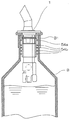
図5は、液体注出具1の作用を説明するための断面図であり、図5(A)は注出前の状態を示し、図5(B)は注出初期の状態を示し、図5(C)は注出中の状態を示す、図5(D)は注出終期もしくは注出停止状態を、それぞれ示している。ここでは、ボトルは記載されていないが、実際にはボトルに装着されている状態を想定して説明する。
[Action of liquid pouring tool]
FIG. 5 is a cross-sectional view for explaining the action of the liquid dispensing tool 1, FIG. 5 (A) shows a state before dispensing, FIG. 5 (B) shows an initial state of dispensing, and FIG. C) shows a state during the pouring, and FIG. 5D shows the end of the pouring or the pouring stopped state, respectively. Here, although the bottle is not described, the description will be made assuming that the bottle is actually attached to the bottle.

先ず、図5(A)に示すように、ボトルに装着された状態では、液体注出具1は注出部11が上方で計量部21が下方となるような姿勢となる。この状態では、計量部21内の第1金属球27は蓋部材40の内部端面に接触しており、第2金属球47は保持突起46によって第2弁座部45から最も離れた位置に保持されている。基本的に、当該姿勢のときには、液体注出具1内には液体は充填されていない。   First, as shown in FIG. 5 (A), in a state of being mounted on a bottle, the liquid pouring tool 1 is in such a posture that the pouring part 11 is upward and the measuring part 21 is downward. In this state, the first metal ball 27 in the measuring portion 21 is in contact with the inner end surface of the lid member 40, and the second metal ball 47 is held at a position farthest from the second valve seat portion 45 by the holding protrusion 46. Has been. Basically, in the posture, the liquid dispensing tool 1 is not filled with liquid.

次に、図5(B)に示すように、ボトルが逆さまにされる過程で、液体注出具1が略水平になる。このとき、液体注出具1の内部には液体通過穴25を通して液体が進入する。また、第2金属球47は連通路43の第2弁座部45に当接していないので、この連通路43を通って液体が計量部21の内部空間23に進入する。この姿勢において、計量部21の内部空間23はほぼ全体が液体で満たされていることが望ましい。   Next, as shown in FIG. 5B, in the process of turning the bottle upside down, the liquid dispensing tool 1 becomes substantially horizontal. At this time, the liquid enters the liquid pouring tool 1 through the liquid passage hole 25. Further, since the second metal ball 47 is not in contact with the second valve seat portion 45 of the communication path 43, the liquid enters the internal space 23 of the measuring unit 21 through the communication path 43. In this posture, it is preferable that the entire internal space 23 of the measuring unit 21 is filled with liquid.

次に、図5(C)に示すように、液体注出具1が更に傾けられる。すると、第2金属球47は第2弁座部45に当接して、もはや連通路43からの液体の流入は停止される。一方、液体通過穴25からの液体の流入は継続される。この状態で、第1金属球27は計量部21の内部空間23に充填されている液体の抵抗によって、第1弁座部29まで沈降するのに所定の時間を必要とする。このため、第1金属球27が第1弁座部29に当接していない状態が維持される。第1金属球27が第1弁座部29に到達するまでの間は、ボトル内の液体は液体通過穴25を通して注出部11に供給され続ける。   Next, as shown in FIG. 5 (C), the liquid dispensing tool 1 is further tilted. Then, the second metal ball 47 comes into contact with the second valve seat 45 and the inflow of the liquid from the communication passage 43 is stopped. On the other hand, the inflow of the liquid from the liquid passage hole 25 is continued. In this state, the first metal ball 27 needs a predetermined time to settle down to the first valve seat portion 29 due to the resistance of the liquid filled in the internal space 23 of the measuring portion 21. For this reason, the state in which the first metal ball 27 is not in contact with the first valve seat portion 29 is maintained. Until the first metal ball 27 reaches the first valve seat portion 29, the liquid in the bottle continues to be supplied to the dispensing portion 11 through the liquid passage hole 25.

このとき、ボトル内に十分な量の液体が残存している場合には、蓋部材40側の開口部48も液体内に水没することとなる。このため、蓋部材40側の開口部48から液体が逆流して進入することも考えられる。しかしながら、蓋部材40側の開口部48には、断面積が大きな空間からなる空気溜まり42が形成されており、直接空気通路41、31に液体が逆流するのを防止する機能を有している。したがって、空気通路41の注出部11側の開口部11cから液体が漏洩(液だれ)するのを防止することが可能となる。   At this time, if a sufficient amount of liquid remains in the bottle, the opening 48 on the lid member 40 side is also submerged in the liquid. For this reason, it is also conceivable that the liquid flows back and enters from the opening 48 on the lid member 40 side. However, an air reservoir 42 having a large cross-sectional area is formed in the opening 48 on the lid member 40 side, and has a function of preventing the liquid from flowing back into the air passages 41 and 31 directly. . Therefore, it is possible to prevent the liquid from leaking (spilling) from the opening 11c on the outlet 11 side of the air passage 41.

図5(D)は、注出過程の終期および注出停止状態を示している。第1金属球27は、所定時間を経過した段階で、計量部21の内部空間23の液体中を沈降し、第1弁座部29に当接する。これにより、注出部11への液体の供給は停止されることとなり、注出過程が終了する。そして、ボトルを元の姿勢に戻すことにより、図5(A)の注出前の状態となる。そして、図5に示す一連のステップによって、一定量の液体が計量されるのである。   FIG. 5D shows the end of the extraction process and the extraction stop state. The first metal ball 27 settles in the liquid in the internal space 23 of the measuring unit 21 at a stage when a predetermined time has elapsed, and comes into contact with the first valve seat 29. Thereby, supply of the liquid to the extraction part 11 will be stopped, and the extraction process will be complete | finished. And it will be in the state before pouring of Drawing 5 (A) by returning a bottle to an original posture. Then, a certain amount of liquid is measured by a series of steps shown in FIG.

本願発明は、ボトルの口に装着されてボトル内の液体を一定量注出するための液体注出具に利用可能である。   The present invention is applicable to a liquid dispensing tool that is attached to the mouth of a bottle and that dispenses a certain amount of liquid in the bottle.

1 液体注出具
11 注出部
21 計量部
31 空気通路
41 空気通路
42 空気溜まり
51 密封部材
54a 第1シール
54b 第2シール
DESCRIPTION OF SYMBOLS 1 Liquid pouring tool 11 Pouring part 21 Metering part 31 Air path 41 Air path 42 Air reservoir 51 Sealing member 54a 1st seal 54b 2nd seal

Claims (15)

ボトルの口に装着されて、ボトル内の液体を一定量注出するための液体注出具であって、
ボトルの外部へ抽出する液体を計量して注出する管状の計量抽出部と、ボトルの外部から内部へ空気を通すための空気通路とを備え、
前記空気通路はその内部の空気の流れが屈折又は変曲するように形成されていると共に、前記空気通路の途中には当該空気通路の断面積よりも大きな断面積を有する空気溜まりが形成されており、
前記計量抽出部は、ボトル内から注出した液体を計量する計量部と、該計量部に連通され液体をボトルの外部へ注出する注出部とからなり、
前記空気通路は、前記計量部に沿って配置されていることを特徴とする、液体注出具。
A liquid dispenser that is attached to the mouth of a bottle to pour out a certain amount of liquid in the bottle,
A tubular metering and extracting section for metering and dispensing the liquid to be extracted to the outside of the bottle, and an air passage for passing air from the outside to the inside of the bottle,
The air passage is formed so that the flow of air inside thereof is refracted or bent, and an air pocket having a cross-sectional area larger than the cross-sectional area of the air passage is formed in the middle of the air passage. And
The metering extraction unit comprises a metering unit for metering the liquid poured out from the bottle, and a pouring unit communicating with the metering unit for pouring the liquid to the outside of the bottle,
The liquid extraction tool, wherein the air passage is disposed along the measuring portion .
ボトルの口に装着されて、ボトル内の液体を一定量注出するための液体注出具であって、  A liquid dispenser that is attached to the mouth of a bottle to pour out a certain amount of liquid in the bottle,
ボトルの外部へ抽出する液体を計量して注出する管状の計量抽出部と、ボトルの外部から内部へ空気を通すための空気通路とを備え、前記空気通路は、ボトルの液体収容空間内に配置される開口部を有しており、  A tubular metering / extracting portion for metering and dispensing the liquid to be extracted to the outside of the bottle; and an air passage for allowing air to pass from the outside to the inside of the bottle, the air passage being in the liquid storage space of the bottle Has an opening to be placed,
前記空気通路はその内部の空気の流れが屈折又は変曲するように形成されていると共に、前記空気通路の途中には当該空気通路の断面積よりも大きな断面積を有する空気溜まりが形成されていることを特徴とする、液体抽出具。  The air passage is formed so that the flow of air inside thereof is refracted or bent, and an air pocket having a cross-sectional area larger than the cross-sectional area of the air passage is formed in the middle of the air passage. A liquid extractor characterized by comprising:
前記計量抽出部は、ボトル内から注出した液体を計量する計量部と、該計量部に連通され液体をボトルの外部へ注出する注出部とからなり、
前記空気通路は、前記計量部に沿って配置されていることを特徴とする、請求項に記載の液体注出具。
The metering extraction unit comprises a metering unit for metering the liquid poured out from the bottle, and a pouring unit communicating with the metering unit for pouring the liquid to the outside of the bottle,
The liquid dispensing tool according to claim 2 , wherein the air passage is disposed along the measuring portion.
前記空気溜まりは、前記空気通路内の空気の流れが屈折又は変曲する位置のうち少なくとも1箇所に配されていることを特徴とする、請求項1又は3に記載の液体注出具。 The air pocket is characterized in that the air flow in said air passage is disposed in at least one position of the positions refraction or inflection, liquid Note Daegu according to claim 1 or 3. 前記空気溜まりは、前記空気通路内の空気の流れが屈折又は変曲する位置のうち少なくとも1箇所に配されていることを特徴とする、請求項2に記載の液体注出具。The liquid pouring tool according to claim 2, wherein the air reservoir is disposed at at least one of positions where the air flow in the air passage is refracted or bent. 前記空気溜まりは、前記空気通路におけるボトル側の末端部に設けられていることを特徴とする、請求項1、3又は4に記載の液体注出具。 The air reservoir is characterized in that provided in the end portion of the bottle side in the air passage, the liquid Note Daegu according to claim 1, 3 or 4. 前記空気溜まりは、前記空気通路におけるボトル側の末端部に設けられていることを特徴とする、請求項2又は5に記載の液体注出具。6. The liquid dispensing tool according to claim 2, wherein the air reservoir is provided at a bottle-side end portion of the air passage. 前記空気通路は、前記計量部に沿って略直線状に形成されており、前記空気溜まりにおいて折れ曲がっていることを特徴とする、請求項1、3、4又は6に記載の液体注出具。 The liquid dispensing tool according to claim 1, 3, 4, or 6 , wherein the air passage is formed in a substantially linear shape along the measuring portion, and is bent in the air reservoir. 前記計量部の外周部には、ボトルへの固定及び液体のボトル外への漏洩を防止するための密封部材が装着されていることを特徴とする、請求項1、3、4、6又は8に記載の液体注出具。 The outer peripheral part of the said measuring part is equipped with the sealing member for preventing fixation to a bottle and leakage of the liquid outside a bottle, The 1, 3, 4, 6 or 8 characterized by the above-mentioned. Liquid dispenser as described in 1. 前記密封部材の外周面には、大きさの異なる複数の環状シールが形成されており、前記注出部に近い側に、最も直径の大きな環状の第1シールが設けられていることを特徴とする、請求項に記載の液体注出具。 A plurality of annular seals having different sizes are formed on the outer peripheral surface of the sealing member, and an annular first seal having the largest diameter is provided on the side close to the dispensing portion. The liquid extraction tool according to claim 8 . 前記第1シールのボトル側には、第1シールから離れて少なくとも1つの環状の第2シールが設けられていることを特徴とする、請求項10に記載の液体注出具。 The liquid dispensing tool according to claim 10 , wherein at least one annular second seal is provided on the bottle side of the first seal so as to be separated from the first seal. 前記第2のシールは4つ設けられていることを特徴とする、請求項11に記載の液体注出具。 The liquid dispensing tool according to claim 11 , wherein four second seals are provided. 前記第1シール及び少なくとも2つの第2シールとは、不等間隔に配置されていることを特徴とする、請求項10又は11に記載の液体注出具。 The liquid dispensing tool according to claim 10 or 11 , wherein the first seal and the at least two second seals are arranged at unequal intervals. 前記第1シールの直径は23mmであり、前記第2シールの直径は21mmであることを特徴とする、請求項11〜13のいずれか一項に記載の液体注出具。 The diameter of the said 1st seal | sticker is 23 mm, The diameter of the said 2nd seal | sticker is 21 mm, The liquid extraction tool as described in any one of Claims 11-13 characterized by the above-mentioned. 前記第1シールと第2シールとの間隔は5.5mmであり、隣接する複数の第2シール同士の間隔は3mmまたは3.5mmである、請求項12〜14のいずれか一項に記載の液体注出具。 The space | interval of the said 1st seal | sticker and a 2nd seal | sticker is 5.5 mm, and the space | interval of several adjacent 2nd seals is 3 mm or 3.5 mm, It is any one of Claims 12-14 Liquid pouring tool.
JP2011191810A 2011-09-02 2011-09-02 Liquid pouring tool Active JP5801657B2 (en)

Priority Applications (1)

Application Number Priority Date Filing Date Title
JP2011191810A JP5801657B2 (en) 2011-09-02 2011-09-02 Liquid pouring tool

Applications Claiming Priority (1)

Application Number Priority Date Filing Date Title
JP2011191810A JP5801657B2 (en) 2011-09-02 2011-09-02 Liquid pouring tool

Publications (2)

Publication Number Publication Date
JP2013052897A JP2013052897A (en) 2013-03-21
JP5801657B2 true JP5801657B2 (en) 2015-10-28

Family

ID=48130264

Family Applications (1)

Application Number Title Priority Date Filing Date
JP2011191810A Active JP5801657B2 (en) 2011-09-02 2011-09-02 Liquid pouring tool

Country Status (1)

Country Link
JP (1) JP5801657B2 (en)

Families Citing this family (4)

* Cited by examiner, † Cited by third party
Publication number Priority date Publication date Assignee Title
JP6418370B2 (en) * 2013-11-27 2018-11-07 紀伊産業株式会社 Quantitative polar
KR101780741B1 (en) * 2015-11-27 2017-10-10 주식회사 이한산업 Plastic barrel flexible hose
KR101691133B1 (en) * 2016-02-17 2016-12-29 주식회사 이한산업 Functional plastic barrel
CN108692080A (en) * 2017-04-10 2018-10-23 朱艳青 It is a kind of to control quantitative fuel-displaced valve body structure

Family Cites Families (4)

* Cited by examiner, † Cited by third party
Publication number Priority date Publication date Assignee Title
JPS4210952Y1 (en) * 1965-12-26 1967-06-16
US5961008A (en) * 1996-11-19 1999-10-05 Peckels; Arganius E. Method and apparatus for pouring liquid from a bottle
JP5994112B2 (en) * 2010-02-15 2016-09-21 俊太郎 阿部 Fluid substance storage container and its lid
JP3159427U (en) * 2010-03-01 2010-05-20 宮崎県酒造組合 Suction bottle container spout aid

Also Published As

Publication number Publication date
JP2013052897A (en) 2013-03-21

Similar Documents

Publication Publication Date Title
JP5801657B2 (en) Liquid pouring tool
US20130008919A1 (en) Apparatus and methods for dispensing fluid
US20090159620A1 (en) Dispensing device for dispensing a liquid product
WO2012112774A1 (en) Venturi device and method
CN107098075B (en) Container capable of being quantified
JP5669486B2 (en) Liquid dispensing container
ZA200708155B (en) Liquid dispensing apparatus and device
JP6418370B2 (en) Quantitative polar
JP2011178466A (en) Measuring cap and liquid container
CN109649816B (en) Stable pouring type quantitative liquid dispenser
JP2007191186A (en) Capped container
JP2010215250A (en) Liquid-measuring and discharging container
CN109625583B (en) Dumping type quantitative adjustable liquid distributor
CN209739719U (en) Stable formula ration liquid distributor that emptys
CN109649815B (en) Dumping type quantitative liquid distributor with hydraulic compensation function
JP5373554B2 (en) Spout
JP6903480B2 (en) Noter
CN109649817B (en) Pouring type quantitative liquid distributor capable of delaying liquid discharge
JPH0344678Y2 (en)
JP7225651B2 (en) cap with nozzle
JP6160992B2 (en) Pouring nozzle with measuring device
KR102187341B1 (en) Cap for draining constant quantity of liquid
JP4757526B2 (en) Weighing cap
JP6628662B2 (en) Dispenser with measuring cap
JP3125538U (en) funnel

Legal Events

Date Code Title Description
A621 Written request for application examination

Free format text: JAPANESE INTERMEDIATE CODE: A621

Effective date: 20140821

A977 Report on retrieval

Free format text: JAPANESE INTERMEDIATE CODE: A971007

Effective date: 20150430

A131 Notification of reasons for refusal

Free format text: JAPANESE INTERMEDIATE CODE: A131

Effective date: 20150507

A521 Request for written amendment filed

Free format text: JAPANESE INTERMEDIATE CODE: A523

Effective date: 20150706

TRDD Decision of grant or rejection written
A01 Written decision to grant a patent or to grant a registration (utility model)

Free format text: JAPANESE INTERMEDIATE CODE: A01

Effective date: 20150728

A61 First payment of annual fees (during grant procedure)

Free format text: JAPANESE INTERMEDIATE CODE: A61

Effective date: 20150827

R150 Certificate of patent or registration of utility model

Ref document number: 5801657

Country of ref document: JP

Free format text: JAPANESE INTERMEDIATE CODE: R150

S111 Request for change of ownership or part of ownership

Free format text: JAPANESE INTERMEDIATE CODE: R313115

R360 Written notification for declining of transfer of rights

Free format text: JAPANESE INTERMEDIATE CODE: R360

R370 Written measure of declining of transfer procedure

Free format text: JAPANESE INTERMEDIATE CODE: R370

S111 Request for change of ownership or part of ownership

Free format text: JAPANESE INTERMEDIATE CODE: R313115

R350 Written notification of registration of transfer

Free format text: JAPANESE INTERMEDIATE CODE: R350

R250 Receipt of annual fees

Free format text: JAPANESE INTERMEDIATE CODE: R250

R250 Receipt of annual fees

Free format text: JAPANESE INTERMEDIATE CODE: R250

R250 Receipt of annual fees

Free format text: JAPANESE INTERMEDIATE CODE: R250

R250 Receipt of annual fees

Free format text: JAPANESE INTERMEDIATE CODE: R250

R250 Receipt of annual fees

Free format text: JAPANESE INTERMEDIATE CODE: R250