JP5801038B2 - Image display device and image display method - Google Patents
Image display device and image display method Download PDFInfo
- Publication number
- JP5801038B2 JP5801038B2 JP2010169704A JP2010169704A JP5801038B2 JP 5801038 B2 JP5801038 B2 JP 5801038B2 JP 2010169704 A JP2010169704 A JP 2010169704A JP 2010169704 A JP2010169704 A JP 2010169704A JP 5801038 B2 JP5801038 B2 JP 5801038B2
- Authority
- JP
- Japan
- Prior art keywords
- image
- switching
- amount
- instruction
- corresponding image
- Prior art date
- Legal status (The legal status is an assumption and is not a legal conclusion. Google has not performed a legal analysis and makes no representation as to the accuracy of the status listed.)
- Expired - Fee Related
Links
Images


Classifications
-
- G—PHYSICS
- G06—COMPUTING; CALCULATING OR COUNTING
- G06F—ELECTRIC DIGITAL DATA PROCESSING
- G06F16/00—Information retrieval; Database structures therefor; File system structures therefor
- G06F16/50—Information retrieval; Database structures therefor; File system structures therefor of still image data
- G06F16/54—Browsing; Visualisation therefor
Description
本発明は、画像を表示する画像表示装置及び画像表示方法に関する。 The present invention relates to an image display device and an image display method for displaying an image.
近年、撮像した画像(動画像、静止画像を含む)をフィルムではなくデータとして記録媒体に記録するデジタル方式の撮像装置が広く普及している。このような撮像装置では、撮像して得られた画像データを多数記録したり、事後的に任意の画像データを消去したりすることが可能である。そのためユーザは、満足した画像が得られるまで、気軽に多数の画像を撮像することができる。 In recent years, digital imaging devices that record captured images (including moving images and still images) as data instead of film on recording media have become widespread. In such an imaging apparatus, it is possible to record a large number of image data obtained by imaging, or to delete arbitrary image data afterwards. Therefore, the user can easily take a large number of images until a satisfactory image is obtained.
ユーザは、撮像装置に付属するモニタやフォトフレームなどのビューアに代表される画像表示装置を用いて、画像データを再生(動画像を再生、静止画像を表示)する。ユーザは、例えばタッチパネルなどで構成される操作部を用いて、再生すべき画像データを選択する。また、画像表示装置の中には、サムネイル画像などの画像データに対応する画像(以下、対応画像とする)を表示することで、選択を容易にするものがある。 The user reproduces the image data (plays back a moving image and displays a still image) using an image display device represented by a viewer such as a monitor or a photo frame attached to the imaging device. The user selects image data to be reproduced using an operation unit configured with, for example, a touch panel. Some image display devices facilitate selection by displaying an image corresponding to image data such as a thumbnail image (hereinafter referred to as a corresponding image).
ただし、画像表示装置の表示画面の大きさには制限があり、一度に多数の対応画像を明確に表示することは困難となる。そのため、ユーザは操作部を操作して、所望の画像データの対応画像が表示されるまで、表示される対応画像を順次切り替える必要がある。 However, the size of the display screen of the image display device is limited, and it is difficult to clearly display many corresponding images at once. Therefore, the user needs to sequentially switch the displayed corresponding images until the corresponding image of the desired image data is displayed by operating the operation unit.
このとき、上述のように多数の画像データが存在すると、ユーザが所望の画像データを選択するまでに、多数回の切り替えが必要となる場合が生じる。具体的には、対応画像を多数回送る(次の対応画像を表示する)または多数回戻す(前の対応画像を表示する)ことが必要となる場合が生じる。そのため、所望の画像データを選択するまでの操作が煩雑になることがあり、問題となる。 At this time, if there are a large number of image data as described above, it may be necessary to switch many times before the user selects the desired image data. Specifically, it may be necessary to send the corresponding image many times (display the next corresponding image) or return many times (display the previous corresponding image). For this reason, the operation until the desired image data is selected may be complicated, which causes a problem.
さらに、例えば同じ構図、同じ場所や同じ時間帯などで撮像されて得られた画像データが複数存在し、当該画像データの中には所望する画像データが存在しないとユーザが判断した場合、ユーザは当該画像データの対応画像を注視する必要がないため、迅速に所望の画像データを選択するべく当該対応画像を高速で送るまたは戻す(一度の操作で多数の対応画像を送るまたは戻す)ことが多くなる。すると、所望の画像データの対応画像の表示を通りすぎてしまう「送り過ぎ」や「戻し過ぎ」が生じ、所望の画像データを選択するまでに時間を要するため、問題となる。 Further, for example, when there are a plurality of image data obtained by imaging in the same composition, the same place, the same time zone, etc., and the user determines that the desired image data does not exist in the image data, the user Since there is no need to gaze at the corresponding image of the image data, the corresponding image is often sent or returned at a high speed so that desired image data can be selected quickly (multiple corresponding images are sent or returned in one operation). Become. This causes a problem because “overfeed” and “return” that pass through the display of the corresponding image of the desired image data occur, and it takes time to select the desired image data.
そこで、特許文献1では、ある選択された画像データに類似する画像データの縮小画像を類似順に表示し、その中からさらに選択された画像データに関連する画像データの縮小画像のみを表示することにより、少ない操作で迅速に所望の画像データを選択可能とする画像表示装置が提案されている。
Therefore, in
また、特許文献2では、複数の画像データが属するグループの中から、代表となる画像データを各グループにおいて決定し、決定した画像データの縮小画像を並べて表示する画像表示装置が提案されている。当該画像表示装置は、いずれかの代表となる画像データがユーザによって選択されると、当該画像データと同じグループに属する画像データの縮小画像を、並べて表示する。
しかしながら特許文献1に記載の画像表示装置では、類似したり関連したりする画像データが少ない画像データについては、その縮小画像を優先的に表示することができないため、捜索が困難になる。また、特許文献2に記載の画像表示装置では、属するグループが分からない画像データの捜索が困難になる。したがって、これらの画像データをユーザが選択しようとする場合、ユーザは、従来と同様に多数の対応画像を順次送るまたは戻すことにより、選択すべき画像を捜索する必要がある。すると、操作が煩雑化したり、「送り過ぎ」や「戻し過ぎ」を生じて画像データの選択に時間を要したりするため、問題となる。
However, in the image display device described in
そこで、本発明は、ユーザが容易かつ迅速に所望の画像データを選択可能とする画像表示装置及び画像表示方法を提供することを目的とする。 SUMMARY An advantage of some aspects of the invention is that it provides an image display device and an image display method that enable a user to select desired image data easily and quickly.
上記目的を達成するために本発明の画像表示装置は、所定の順番を有する対応画像を少なくとも1つ表示する表示部と、前記表示部に表示される対応画像を、前記順番の順方向又は逆方向に沿って切り替えるための切替指示が入力される入力部と、前記切替指示に従って前記表示部に表示されている第1対応画像を切り替える切替制御部と、を備えた画像表示装置であって、前記切替制御部は、前記第1対応画像と、少なくとも第2対応画像との相関関係が密接でない場合には、前記切替指示に応じて決まる第1切替量で対応画像を切り替え、当該相関関係が密接である場合には、前記第1切替量よりも大きい第2切替量で対応画像を切り替え、前記第2対応画像は、前記切替制御部が前記順方向に沿って対応画像を切り替える場合は前記第1対応画像に対して前記順番が直後の対応画像であり、前記切替制御部が前記逆方向に沿って対応画像を切り替える場合は前記第1対応画像に対して前記順番が直前の対応画像であり、前記第1切替量及び前記第2切替量が、単位動作当たりまたは単位時間当たりに切り替えられる対応画像の数であることを特徴とする。
The image display device of the present invention in order to achieve the above object, a display unit for at least one display the corresponding images having a predetermined order, the corresponding image displayed on the display unit, a forward or reverse of the order An image display device comprising: an input unit that receives a switching instruction for switching along a direction; and a switching control unit that switches a first corresponding image displayed on the display unit according to the switching instruction, When the correlation between the first corresponding image and at least the second corresponding image is not close, the switching control unit switches the corresponding image with a first switching amount determined according to the switching instruction, and the correlation is If close, the corresponding image is switched with a second switching amount that is larger than the first switching amount , and the second corresponding image is displayed when the switching control unit switches the corresponding image along the forward direction. First When the order is the corresponding image immediately after the corresponding image, and the switching control unit switches the corresponding image along the reverse direction, the order is the immediately preceding corresponding image with respect to the first corresponding image, It said first switching amount and the second switching amount, wherein the number der Rukoto corresponding image is switched in the unit operation or per unit time.
なお、以下の実施形態では、入力部の一例として操作部を挙げ、切替制御部の一例として表示制御部を挙げて、それぞれ説明している。 In the following embodiments, an operation unit is exemplified as an example of an input unit, and a display control unit is exemplified as an example of a switching control unit.
このように構成すると、ユーザが所望しない相関関係が密接である対応画像を、容易かつ迅速に切り替えることが可能となる。そのため、ユーザが所望する対応画像を容易かつ迅速に表示させることが可能となる。 If comprised in this way, it will become possible to switch the corresponding image with the close correlation which a user does not desire close closely and easily. Therefore, it is possible to easily and quickly display the corresponding image desired by the user.
また、上記構成の画像表示装置において、前記第2切替量が、前記表示部に表示されている対応画像と、当該対応画像から前記順番に沿って連続しておりそれぞれが当該対応画像と相関関係が密接である対応画像と、を切り替える大きさであることとしても構わない。 Further, in the image display device having the above-described configuration, the second switching amount is continuous with the corresponding image displayed on the display unit in the order from the corresponding image, and each is correlated with the corresponding image. May be a size for switching between corresponding images that are close to each other.
このように構成すると、ユーザが所望しない相関関係が密接である対応画像を、まとめて切り替えることが可能となる。そのため、ユーザが所望する対応画像を容易かつ迅速に表示させることが可能となる。 If comprised in this way, it will become possible to switch the corresponding image with the close correlation which a user does not want closely. Therefore, it is possible to easily and quickly display the corresponding image desired by the user.
また、上記構成の画像表示装置において、前記切替指示が指示量を示し、当該指示量の増大に応じて前記第1切替量が増大するものであり、前記入力部に前記指示量が所定の大きさ以下となる切替指示が入力されるとき、前記第1対応画像と少なくとも前記第2対応画像との相関関係が密接であっても、前記第2切替量が前記第1切替量と等しくなることとしても構わない。
In the image display device having the above-described configuration, the switching instruction indicates an instruction amount, and the first switching amount increases in accordance with the increase in the instruction amount. When a switching instruction that is less than or equal to is input , even if the correlation between the first corresponding image and at least the second corresponding image is close, the second switching amount is equal to the first switching amount. It does not matter.
このように構成すると、相関関係が密接である対応画像を切り替える場合であっても、指示量が所定の大きさ以下となる切替指示を入力部に入力するだけで、第2切替量が無用に大きくなることを抑制することが可能となる。そのため、相関関係が密接である対応画像の中に所望する対応画像が存在する場合など、必要に応じて第2切替量を容易に小さくすることが可能となる。 With this configuration, even when the corresponding images having a close correlation are switched, the second switching amount can be used simply by inputting a switching instruction that causes the instruction amount to be a predetermined size or less to the input unit. It becomes possible to suppress the increase. For this reason, the second switching amount can be easily reduced as necessary, for example, when a desired corresponding image is present in the corresponding images having a close correlation.
また、上記構成の画像表示装置において、前記切替指示が指示量を示し、当該指示量の増大に応じて前記第1切替量が増大するものであり、前記入力部に前記指示量が所定の大きさ以上となる切替指示が入力されるとき、前記第1切替量及び前記第2切替量にかかわらず、対応画像が属するカテゴリごとに切り替えられることとしても構わない。 In the image display device having the above-described configuration, the switching instruction indicates an instruction amount, and the first switching amount increases in accordance with the increase in the instruction amount. When a switching instruction that is greater than or equal to this is input, switching may be performed for each category to which the corresponding image belongs regardless of the first switching amount and the second switching amount.
このように構成すると、指示量が所定の大きさ以上となる切替指示を入力部に入力するだけで、対応画像をカテゴリ単位で切り替えることが可能となる。そのため、対応画像をカテゴリ単位で絞り込むことが可能となり、容易かつ迅速に所望の対応画像を表示させることが可能となる。 If comprised in this way, it will become possible to switch a corresponding | compatible image for every category only by inputting into the input part the switching instruction | indication which becomes more than predetermined magnitude | size. For this reason, the corresponding images can be narrowed down in units of categories, and a desired corresponding image can be displayed easily and quickly.
また、上記構成の画像表示装置において、前記第1切替量が、前記指示量の増大に伴い階段状に増大することとしても構わない。また、前記第1切替量が、前記指示量の増大に伴い線形または非線形に増大することとしても構わない。 In the image display device having the above-described configuration, the first switching amount may increase stepwise as the instruction amount increases. Further, the first switching amount may increase linearly or nonlinearly as the instruction amount increases.
また、上記構成の画像表示装置において、前記表示部が、相関関係が密接である対応画像の少なくとも2つを、1つの対応画像としてまとめて表示することとしても構わない。 In the image display device having the above-described configuration, the display unit may collectively display at least two corresponding images having a close correlation as one corresponding image.
このように構成すると、複数の対応画像がまとめて切り替えられることを、ユーザに直感させやすくすることが可能となる。なお、まとめて表示される対応画像の1つである代表対応画像が、まとめて表示されない他の対応画像と同様に表示されることとしても構わない。また、まとめて表示される対応画像が、まとめて表示されない他の対応画像と区別され得るように報知されることとしても構わない。 If comprised in this way, it will become possible to make it easy for a user to intuitively switch a some corresponding | compatible image collectively. Note that the representative corresponding image that is one of the corresponding images displayed together may be displayed in the same manner as other corresponding images that are not displayed together. Further, the corresponding images displayed together may be notified so as to be distinguished from other corresponding images not displayed together.
また、上記構成の画像表示装置において、前記表示部は、選択される対応画像が対応する画像データを再生するものであり、相関関係が密接である複数の対応画像の少なくとも1つが選択されたことで、前記表示部が、当該複数の対応画像のいずれか1つが対応する画像データを再生しているとき、前記入力部を介して切替指示とは異なる指示が入力される、または、前記入力部に所定の時間以上指示が入力されないと、再生していない当該複数の対応画像のいずれか1つが対応する画像データを、前記表示部が再生するように変更することとしても構わない。 In the image display device having the above-described configuration, the display unit reproduces image data corresponding to the selected corresponding image, and at least one of the plurality of corresponding images having close correlation is selected. Thus, when the display unit reproduces image data corresponding to any one of the plurality of corresponding images, an instruction different from the switching instruction is input via the input unit, or the input unit If an instruction is not input for a predetermined time or more, image data corresponding to any one of the plurality of corresponding images that have not been reproduced may be changed to be reproduced by the display unit.
このように構成すると、相関関係が密接である複数の対応画像が対応するそれぞれの画像データを、ユーザが容易に再生して確認することが可能となる。 If comprised in this way, it will become possible for a user to reproduce | regenerate and confirm each image data with which the some corresponding | compatible image with close correlation respond | corresponds easily.
また、上記構成の画像表示装置において、前記表示部は、相関関係が密接である複数の対応画像のいずれか1つを、当該複数の対応画像に含まれる他の対応画像よりも優先的に表示するものであり、前記入力部を介して切替指示とは異なる指示が入力される、または、前記入力部に所定の時間以上指示が入力されないと、優先的に表示していない当該複数の対応画像のいずれか1つを、前記表示部が優先的に表示するように変更することとしても構わない。 In the image display device having the above configuration, the display unit preferentially displays any one of a plurality of corresponding images having a close correlation with each other over other corresponding images included in the plurality of corresponding images. The plurality of corresponding images that are not preferentially displayed when an instruction different from the switching instruction is input via the input unit, or when an instruction is not input to the input unit for a predetermined time or more Any one of the above may be changed so that the display unit preferentially displays.
このように構成すると、相関関係が密接である複数の対応画像を、ユーザが容易に確認することが可能となる。 With this configuration, the user can easily confirm a plurality of corresponding images having close correlation.
また、上記構成の画像表示装置において、前記表示部は、相関関係が密接である複数の対応画像のいずれか1つを、当該複数の対応画像に含まれる他の対応画像よりも優先的に表示するものであり、前記表示部は、当該複数の対応画像の中で、直近に選択された対応画像を優先的に表示することとしても構わない。 In the image display device having the above configuration, the display unit preferentially displays any one of a plurality of corresponding images having a close correlation with each other over other corresponding images included in the plurality of corresponding images. The display unit may preferentially display a corresponding image selected most recently among the plurality of corresponding images.
このように構成すると、ユーザが選択する可能性の高い対応画像を、優先的に表示することが可能となる。そのため、ユーザが容易に所望の対応画像を選択することが可能となる。 If comprised in this way, it will become possible to display a corresponding image with high possibility of a user's selection preferentially. Therefore, the user can easily select a desired corresponding image.
また、上記構成の画像表示装置において、相関関係が密接である複数の対応画像の少なくとも1つが選択されたとき、前記表示部が、当該複数の対応画像を別々に表示することとしても構わない。 In the image display device having the above-described configuration, when at least one of a plurality of corresponding images having close correlation is selected, the display unit may display the plurality of corresponding images separately.
このように構成すると、相関関係が密接である複数の対応画像を、ユーザが一度で容易に確認することが可能となる。 If comprised in this way, it will become possible for a user to confirm the some corresponding | compatible image with close correlation easily at once.
また、上記構成の画像表示装置において、前記入力部を介して切替指示とは異なる指示が入力される、または、前記入力部に所定の時間以上指示が入力されないことで、対応画像が選択されることとしても構わない。 Further, in the image display device having the above configuration, an instruction different from the switching instruction is input through the input unit, or a corresponding image is selected when an instruction is not input to the input unit for a predetermined time or more. It doesn't matter.
また、上記構成の画像表示装置において、前記表示部が、前記入力部の操作方法を示す画像を表示することとしても構わない。 In the image display device having the above-described configuration, the display unit may display an image indicating an operation method of the input unit.
このように構成すると、ユーザは、表示部に表示される操作方法を示す画像を見ながら、操作部を操作することになる。そのため、ユーザが容易に表示部を所望の状態にすることが可能になる。 If comprised in this way, a user will operate an operation part, seeing the image which shows the operation method displayed on a display part. Therefore, the user can easily bring the display unit into a desired state.
また、上記構成の画像表示装置において、対応画像が、撮像により得られる画像データに対応する画像であり、前記順番が、画像データの撮像時間順または撮像順であり、まとめて表示される対応画像の中で前記順番が最後となる対応画像を、前記代表対応画像としても構わない。 In the image display device having the above-described configuration, the corresponding image is an image corresponding to image data obtained by imaging, and the order is the imaging time order or imaging order of the image data, and the corresponding images displayed together. The corresponding image in the last order may be used as the representative corresponding image.
このように構成すると、失敗した撮像により得られた可能性が低い画像データの対応画像を、代表対応画像として表示することが可能となる。 If comprised in this way, it will become possible to display the corresponding image of the image data with the low possibility obtained by the failed imaging as a representative corresponding image.
また、上記構成の画像表示装置において、対応画像が、撮像により得られる画像データに対応する画像であり、画像データが示す画像の類否、撮像日時の時間差及び撮像場所の距離差の少なくとも一つに基づいて、相関関係が密接であるか否かが判定されることとしても構わない。 In the image display device having the above configuration, the corresponding image is an image corresponding to the image data obtained by imaging, and at least one of the similarity of the image indicated by the image data, the time difference of the imaging date and time, and the distance difference of the imaging location Based on the above, it may be determined whether or not the correlation is close.
また、上記構成の画像表示装置において、画像データが示す画像が類似するほど、撮像日時の時間差が小さいほどまたは撮像場所の距離差が小さいほど、相関関係が密接であると判定されやすくなることとしても構わない。 Further, in the image display device having the above configuration, as the images indicated by the image data are similar, the smaller the time difference between the imaging dates and times or the smaller the distance difference between the imaging locations, the easier it is to determine that the correlation is closer. It doesn't matter.
また、本発明の画像表示方法は、所定の順番を有する対応画像を少なくとも1つ表示する第1ステップと、前記第1ステップで表示された対応画像を前記順番の順方向又は逆方向に沿って切り替えるための切替指示が入力される第2ステップと、前記第1ステップで表示した第1対応画像を切り替える第3ステップと、を備える画像表示方法であって、前記第3ステップで、前記第1対応画像と、少なくとも、前記第1ステップで前記順方向に沿って対応画像が切り替えられる場合は前記第1対応画像に対して前記順番が直後の対応画像であり、前記第1ステップで前記逆方向に沿って対応画像が切り替えられる場合は前記第1対応画像に対して前記順番が直前の対応画像である第2対応画像との相関関係が密接でない場合には、前記切替指示に応じて決まる第1切替量で対応画像を切り替え、当該相関関係が密接である場合には、前記第1切替量よりも大きい第2切替量で対応画像を切り替え、前記第1切替量及び前記第2切替量が、単位動作当たりまたは単位時間当たりに切り替えられる対応画像の数であることを特徴とする。
The image display method of the present invention includes a first step of displaying at least one corresponding image having a predetermined order, and the corresponding image displayed in the first step along the forward or reverse direction of the order. An image display method comprising: a second step in which a switching instruction for switching is input; and a third step of switching the first corresponding image displayed in the first step. In the third step, the first step and the corresponding image, at least, the case where the corresponding image is switched along said forward in the first step is the corresponding image of immediately after the turn to the first corresponding image, the reverse in the first step along when the order if the corresponding image is switched to the first corresponding image is not closely correlated with the second corresponding image is just before the corresponding picture, the switching finger Switching the corresponding image in the first switching amount determined in accordance with, when the correlation is close switches the corresponding image in the second switching amount greater than the first switching amount, the first switching amount and the second switching amount, wherein the number der Rukoto corresponding image is switched in the unit operation or per unit time.
本発明によると、ユーザが容易かつ迅速に所望の画像データを選択することが可能となる。 According to the present invention, it is possible to Yu over THE selects easily and rapidly a desired image data.
<<画像表示装置の概要>>
本発明の実施形態について、以下図面を参照して説明する。最初に、本発明における画像表示装置の概要について、図1を参照して説明する。図1は、本発明の実施形態における画像表示装置の構成の一例を示すブロック図である。
<< Overview of image display device >>
Embodiments of the present invention will be described below with reference to the drawings. First, an outline of the image display apparatus according to the present invention will be described with reference to FIG. FIG. 1 is a block diagram illustrating an example of a configuration of an image display apparatus according to an embodiment of the present invention.
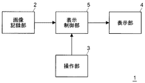
図1に示すように、画像表示装置1は、画像データを記録する画像記録部2と、ユーザの指示が入力される操作部3と、画像を表示する表示部4と、操作部3を介して入力されるユーザの各種指示に基づいて画像記録部2から必要な情報を読み出すとともに表示部4が表示する画像の制御を行う表示制御部5と、を備える。
As shown in FIG. 1, an
画像表示装置1は、画像記録部2に記録されている画像データの中から再生すべき画像データをユーザに選択させる。このとき、表示制御部5は、画像データの対応画像(例えば、画像データ内に添付されたサムネイル画像や、表示制御部5が画像データを調整することで得られる画像(例えば、静止画の縮小画像または動画に含まれる1つのフレームの縮小画像))の少なくとも1つを、表示部4に表示させる。
The
画像記録部2に記録される画像データは、所定の順番を有している。例えば、撮像日時順、撮像順、名前順、ファイル形式順、ユーザが任意で設定した順番や、これらの順番の組み合わせなど、いかなる順番であっても構わない。なお、対応画像は画像データに対応するものであるため、画像データと同様の順番を有していると解釈することができる。また、順番のみに限られず、画像データが有する種々の関係(例えば、相関関係やカテゴリ)も、対応画像が有していると解釈することができる。以下では説明の簡略化のため、対応画像が画像データと同じ順番や関係を有するものとする。
The image data recorded in the
再生すべき画像データを捜索している際の表示部4の表示の一例を、図2に示す。図2は、再生すべき画像データの捜索時における表示部4の表示の一例を示す図である。
An example of the display on the
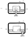
図2(a)に示すように、本例では再生候補画像C10と、前候補画像B10と、次候補画像A10と、の3つの対応画像が表示部4に表示される。具体的には、再生候補画像C10が表示部4の略中央に表示され、その両側に前候補画像B10及び次候補画像A10が表示されるものとしている。なお、前候補画像B10、再生候補画像C10、次候補画像A10の順に、対応画像の順番が連続している。
As shown in FIG. 2A, in this example, three corresponding images of the reproduction candidate image C10, the previous candidate image B10, and the next candidate image A10 are displayed on the
ユーザが操作部3を介して「選択指示」を入力すると、再生候補画像C10が対応する画像データが再生される。また、図2(b)に示すように、ユーザが操作部3を介して「再生候補画像を1つ送る」旨の指示を入力すると、次候補画像A10が再生候補画像C11になり、再生候補画像C10が前候補画像B11になり、次候補画像A10の次の順番の対応画像が次候補画像A11になる。また、図2(c)に示すように、ユーザが操作部3を介して「再生候補画像を1つ戻す」旨の指示を入力すると、前候補画像B10が再生候補画像C12になり、再生候補画像C10が次候補画像A12になり、前候補画像A10の前の順番の対応画像が前候補画像B12になる。
When the user inputs a “selection instruction” via the
再生候補画像C10〜C12は、前候補画像B10〜B12や次候補画像A10〜A12などの他の対応画像と区別し得るものであると好ましい。図2に示す例では、表示制御部5が各対応画像の大きさを調整して、再生候補画像C10〜C12が他の対応画像A10〜A12,B10〜B12よりも大きく表示されるようにしている。なお、これに加えて(または代えて)、例えば再生候補画像C10〜C12の外枠を他の対応画像A10〜A12,B10〜B12と異ならせて表示しても構わないし、他の方法で差異を表現しても構わない。
The reproduction candidate images C10 to C12 are preferably those that can be distinguished from other corresponding images such as the previous candidate images B10 to B12 and the next candidate images A10 to A12. In the example shown in FIG. 2, the
なお、画像表示装置1は、何らかの装置の一部(例えば、撮像装置のモニタ)としても解釈され得るものである。そのため、図1に示す各部は、他の用途のためにも使用され得る。また、対応画像は、画像データに添付されたサムネイル画像や縮小画像のみに限られず、文字画像やアイコンなどであっても構わないし、これらを組み合わせたものであっても構わない。
Note that the
また、図2では「選択指示」入力時の再生候補画像C10〜C12に対応する画像データを再生することとしたが、これに加えて(または代えて)表示中の対応画像の中で、ユーザによって指定された任意の対応画像が対応する画像データが再生されることとしても構わない。また、例えば操作部3がタッチパネルであるとき、ユーザが、所望の対応画像が表示されている位置をタッチ(タップ)することで、当該対応画像を選択する選択指示が入力されることとしても構わない。また、例えば操作部3がトラックボールやキー(タッチパネル上に表示されるキーも含む。以下同じ。)であるとき、ユーザが操作部3を介して所定の対応画像を指定するとともに所定のキーを押下することで、当該対応画像を選択する選択指示が入力されることとしても構わないし、ユーザが所定のキーを押下することで、その時点で再生候補画像C10〜C12となっている対応画像を選択する選択指示が入力されることとしても構わない。
In FIG. 2, the image data corresponding to the reproduction candidate images C10 to C12 when the “selection instruction” is input is reproduced, but in addition to (or instead of) the corresponding image being displayed, The image data corresponding to the arbitrary corresponding image designated by the above may be reproduced. For example, when the
また、図2では表示部4に3つの対応画像が表示される場合について示したが、表示される対応画像を1つまたは2つとしても構わないし、4つ以上としても構わない。
Although FIG. 2 shows the case where three corresponding images are displayed on the
<<対応画像の切替制御>>
次に、再生すべき画像データの捜索時における対応画像の切替制御の詳細について、図面を参照して説明する。
<< Supported image switching control >>
Next, details of switching control of corresponding images at the time of searching for image data to be reproduced will be described with reference to the drawings.
<切替制御:基本>
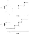
まず、切替制御の基本について、図面を参照して説明する。図3は、指示量と切替量との基本関係の一例を示すグラフである。
<Switching control: Basic>
First, the basics of switching control will be described with reference to the drawings. FIG. 3 is a graph illustrating an example of a basic relationship between the instruction amount and the switching amount.
「指示量」とは、ユーザが操作部3を操作することで表示制御部5に入力される、切替指示の信号値である。原則的に、ユーザが操作部3の一回当たりの(または単位時間当たりの)操作量を大きくしたり、一回当たりの操作時間を長くしたりするほど、指示量は大きくなる。例えば、操作部3がタッチパネルであれば、ユーザが一度に大きくまたは速く一方向にスライドさせる(なぞる)ほど、指示量は大きくなる。また例えば、操作部3がキーであれば、ユーザがあるキーを時間的に長く押し続けるほど、指示量は大きくなる。また例えば、操作部3がトラックボールであれば、ユーザが一方向に速く回転させるほど、指示量は大きくなる。なお、これらは一例に過ぎず、指示量はどのように設定しても構わない。
The “instruction amount” is a signal value of a switching instruction that is input to the
「切替量」とは、操作部3から入力される指示量に基づいて表示制御部5により設定される値であり、表示部4に表示されている対応画像を切り替える量を示すものである。具体的に例えば、単位動作当たりまたは単位時間当たりに切り替えられる対応画像の数と定義することが可能である。ただし、以下では説明の具体化のため、切替量を、一回の切替動作で切り替えられる対応画像の数と定義し、かつ、整数値のみを取り得る(対応画像を画像単位で送るまたは戻す)ものとする。このように定義する場合、図2(a)から図2(b)の状態になる場合の切替量は1となる。
The “switching amount” is a value set by the
図3(a)及び(b)の各グラフは、横軸が1回の操作当たりまたは単位時間当たりの指示量、縦軸が切替量を示すものであり、指示量の増大に伴い切替量が階段状に増大するものである。ただし、図3(a)のグラフでは、切替量を1段階増大させるために必要となる指示量の増大量が、指示量の大きさによらず均一であるが、図3(b)のグラフでは、切替量を1段階増大させるために必要となる指示量の増大量が、指示量が大きくなるほど小さくなる。また、図3(a)のグラフでは切替量に上限値が無いが、図3(b)のグラフでは切替量に上限値があり、ある指示量以上では切替量が一定となる。 In each graph of FIGS. 3A and 3B, the horizontal axis indicates the instruction amount per operation or unit time, and the vertical axis indicates the switching amount. The switching amount increases as the instruction amount increases. It increases in a staircase pattern. However, in the graph of FIG. 3A, the increase amount of the instruction amount required to increase the switching amount by one step is uniform regardless of the size of the instruction amount, but the graph of FIG. Then, the increase amount of the instruction amount required for increasing the switching amount by one step decreases as the instruction amount increases. In addition, although there is no upper limit value for the switching amount in the graph of FIG. 3A, there is an upper limit value for the switching amount in the graph of FIG. 3B, and the switching amount is constant above a specified amount.
なお、図3(a)及び(b)に示す基本関係は一例に過ぎず、他のものとしても構わない。例えば、図3(a)のグラフにおいて切替量に上限値を設けても構わないし、図3(b)のグラフにおいて切替量に上限値を設けないこととしても構わない。 Note that the basic relationships shown in FIGS. 3A and 3B are merely examples, and other relationships may be used. For example, an upper limit value may be provided for the switching amount in the graph of FIG. 3A, or no upper limit value may be provided for the switching amount in the graph of FIG.
また、対応画像を切り替える際に、切替前後の状態のみをユーザに見せるだけでなく、切替の経過(順次対応画像が送られるまたは戻される、動的な様子)をユーザに見せることとしても構わない。このように構成すると、ユーザが切替の内容を容易に認識することができるため、好ましい。 Further, when the corresponding image is switched, not only the state before and after the switching is shown to the user, but also the progress of switching (dynamic state in which the corresponding image is sequentially sent or returned) may be shown to the user. . This configuration is preferable because the user can easily recognize the contents of switching.
<切替制御:相関関係が密接である対応画像>
原則的に、図3(a)または(b)に示すような基本関係に従って設定される切替量により、対応画像の切り替えが行われる。しかしながら、本実施形態の画像表示装置1では、相関関係が密接である(例えば、後述する画像データの相関度が閾値以上となる)対応画像を送るまたは戻すときに、上述の基本関係に従わない切替量が設定される。以下、相関関係が密接である対応画像を切り替える場合の切替制御について、図面を参照して説明する。
<Switching control: Corresponding image with close correlation>
In principle, the corresponding image is switched according to the switching amount set according to the basic relationship as shown in FIG. However, in the
[相関度の算出]
まず、相関度の算出方法例について説明する。相関度は、複数の画像データの各種情報を比較することにより算出される。なお、順番が連続する2つの画像データから相関度を算出しても構わないし、順番が連続する3つ以上の画像データから相関度を算出しても構わない。
[Calculation of correlation]
First, an example of how to calculate the degree of correlation will be described. The degree of correlation is calculated by comparing various pieces of information of a plurality of image data. Note that the degree of correlation may be calculated from two pieces of image data in which the order is continuous, or the degree of correlation may be calculated from three or more pieces of image data in which the order is continuous.
相関度は、例えば画像データの撮像日時、撮像場所、画像データによって示される画像(例えば、静止画または動画に含まれる1つのフレーム。以下、単に画像とも呼ぶ)の類似度、ユーザによる設定や、これらを総合的に判断した結果など、画像データの各種情報を用いて算出することができる。具体的に例えば、撮像日時が近いほど、撮像場所が近いほど、画像が類似している(例えば、画像の類似度が大きい)ほど、相関度が大きくなるものとする。 The correlation degree is, for example, the imaging date and time of the image data, the imaging location, the similarity of an image (for example, one frame included in a still image or a moving image, hereinafter also simply referred to as an image) indicated by the image data, It can be calculated using various information of the image data such as a result of comprehensively determining these. Specifically, for example, the closer the imaging date and time, the closer the imaging location, and the more similar the images (for example, the greater the similarity of the images), the greater the degree of correlation.
画像データの撮像日時を用いて相関度を算出する場合、例えば撮像時に画像データの一部として記録される撮像日時を用いることができる。なお、相関度を算出するそれぞれの画像データの撮像日時の時間差が、所定の時間である基準時間よりも小さくなる場合に、相関度が特に大きくなるようにしても構わない。 When calculating the degree of correlation using the imaging date and time of image data, for example, the imaging date and time recorded as part of the image data at the time of imaging can be used. Note that the degree of correlation may be particularly increased when the time difference between the imaging dates and times of the respective image data for calculating the degree of correlation is smaller than a reference time that is a predetermined time.
撮像場所を用いる場合、例えばGPS(Global Positioning System)を備える撮像装置で撮像した際に画像データの一部として記録される撮像場所を用いることができる。なお、相関度を算出するそれぞれの画像データの撮像場所の距離差が、所定の距離である基準距離よりも小さくなる場合に、相関度が特に大きくなるようにしても構わない。 When using an imaging location, for example, an imaging location that is recorded as part of image data when an image is captured by an imaging device that includes a GPS (Global Positioning System) can be used. It should be noted that the degree of correlation may be particularly increased when the distance difference between the imaging locations of the respective image data for calculating the degree of correlation is smaller than a reference distance that is a predetermined distance.
また、画像の類似度を算出する方法について、以下説明する。画像の類似度は、種々の観点から算出することが可能である。以下では、類似度を算出する第1〜第3の方法についてそれぞれ説明する。なお、第1〜第3の方法のいずれかを用いて類似度を算出しても構わないし、これらを組み合わせて類似度を算出しても構わないものとする。 A method for calculating the similarity of images will be described below. The similarity of images can be calculated from various viewpoints. Below, the 1st-3rd method of calculating a similarity is each demonstrated. Note that the degree of similarity may be calculated using any one of the first to third methods, or the degree of similarity may be calculated by combining them.
まず、第1の方法として、画像内の人数に基づいて類似度を算出する方法について説明する。本方法は、例えば類似度を算出するそれぞれの画像に対して顔検出を行い、それぞれの画像から検出される顔の数(人数)を算出する。そして、それぞれの画像から算出される人数が略等しいものであれば、類似度を大きくする。なお、それぞれの画像から算出される人数が0人で等しくなる場合も、類似度を大きくする。 First, as a first method, a method for calculating the similarity based on the number of people in the image will be described. In this method, for example, face detection is performed on each image for calculating the similarity, and the number (number of people) of faces detected from each image is calculated. If the number of people calculated from each image is substantially equal, the degree of similarity is increased. Note that the degree of similarity is also increased when the number of people calculated from each image is equal to zero.
顔検出を行う場合、公知の種々の技術を適用することが可能である。例えば、Adaboost(Yoav Freund, Robert E. Schapire,"A decision-theoretic generalization of on-line learning and an application to boosting", European Conference on Computational Learning Theory, September 20, 1995.)を利用しても構わない。この方法では、大量の教師サンプル(顔及び非顔のサンプル画像)を識別することで重み付けされた複数の弱識別器により、動画のフレーム中の各部を順次識別することで顔を検出する。 When performing face detection, various known techniques can be applied. For example, Adaboost (Yoav Freund, Robert E. Schapire, "A decision-theoretic generalization of on-line learning and an application to boosting", European Conference on Computational Learning Theory, September 20, 1995.) may be used. . In this method, a face is detected by sequentially identifying each part in a frame of a moving image by using a plurality of weak classifiers weighted by identifying a large number of teacher samples (face and non-face sample images).
次に、第2の方法として、画像内に含まれる人物が同一人物であるか否かに基づいて類似度を算出する方法について説明する。本方法は、例えば類似度を算出するそれぞれの画像に対して顔認識を行い、それぞれの画像から同一人物が検出されるか否かを判定する。そして、それぞれの画像から同一人物が検出されれば、類似度を大きくする。 Next, as a second method, a method for calculating the similarity based on whether or not the persons included in the image are the same person will be described. In this method, for example, face recognition is performed on each image for which similarity is calculated, and it is determined whether or not the same person is detected from each image. If the same person is detected from each image, the degree of similarity is increased.
顔認識を行う場合、公知の種々の技術を適用することが可能である。例えば、予め記録しておいた特定人物のサンプル画像と、顔検出により画像から検出された人物の顔と、を比較することで行っても構わない。また例えば、それぞれの画像から検出された人物の顔同士を比較することで行っても構わない。 When performing face recognition, various known techniques can be applied. For example, it may be performed by comparing a sample image of a specific person recorded in advance with the face of a person detected from the image by face detection. Further, for example, it may be performed by comparing human faces detected from the respective images.
また、第3の方法として、画像の特徴量を表す「特徴ベクトル」を利用して類似度を算出する方法について、図面を参照して説明する。以下では、画像の全体から人物領域を除いた領域である背景領域の特徴ベクトルを用いて特徴ベクトルを算出する方法を例示して説明する。なお、人物領域は、例えば上述のような顔検出により検出された顔領域の位置及び大きさに基づいて、人が含まれる領域を推定することにより算出することができる。また、画像に人が含まれない場合、画像全体を背景領域としても構わない。 As a third method, a method for calculating the similarity using a “feature vector” representing the feature amount of an image will be described with reference to the drawings. In the following, a method for calculating a feature vector using a feature vector of a background region that is a region obtained by removing a person region from the entire image will be described as an example. The person area can be calculated by estimating an area including a person based on the position and size of the face area detected by face detection as described above, for example. Further, when the image does not include a person, the entire image may be used as the background area.
図4及び図5は、特徴ベクトルの算出方法の一例を示す図である。図4に示す画像100は、複数の画素が水平及び垂直方向に配列された二次元画像である。フィルタ111〜115は、画像100中の注目画素101を中心とする小領域(例えば、3×3画素の画像100中の領域)のエッジを抽出するエッジ抽出フィルタである。エッジ抽出フィルタとして、エッジ抽出に適した任意の空間フィルタ(例えば、ソーベルフィルタやプレウィットフィルタなどの微分フィルタ)を用いることができる。ただし、フィルタ111〜115は互いに異なるものとする。なお、図4ではフィルタ111〜115のフィルタサイズ及びフィルタを作用させる小領域を3×3画素として例示したが、5×5画素などの他の大きさにしても構わない。また、使用するフィルタの数を5以外の数としても構わない。
4 and 5 are diagrams illustrating an example of a feature vector calculation method. An
フィルタ111、112、113及び114は、それぞれ画像100の水平方向、垂直方向、右斜方向及び左斜方向に伸びるエッジを抽出し、抽出したエッジの強度の表すフィルタ出力値を出力する。フィルタ115は、水平方向、垂直方向、右斜方向及び左斜方向に分類されない方向に伸びるエッジを抽出し、抽出したエッジの強度を表すフィルタ出力値を出力する。
The
エッジの強度は、画素信号(例えば輝度信号)の勾配の大きさを表す。例えば、画像100の水平方向に伸びるエッジが存在している場合、水平方向に直交する方向である垂直方向において、画素信号に比較的大きな勾配が生じる。また例えば、注目画素101を中心とした小領域にフィルタ111を作用させて空間フィルタリングを行えば、注目画素101を中心とした小領域の垂直方向に沿った画素信号の勾配の大きさがフィルタ出力値として得られる。なお、フィルタ112〜115についても同様である。
The strength of the edge represents the magnitude of the gradient of the pixel signal (for example, luminance signal). For example, when an edge extending in the horizontal direction of the
画像100上のある画素を注目画素101とした状態で、フィルタ111〜115を当該注目画素101を中心とした小領域に作用させることで、5つのフィルタ出力値が得られる。この5つのフィルタ出力値の内、最大のフィルタ出力値を採用フィルタ値として抽出する。最大のフィルタ出力値がフィルタ111〜115からのフィルタ出力値であるときの採用フィルタ値を、それぞれ、第1〜第5の採用フィルタ値と呼ぶ。したがって例えば、最大のフィルタ出力値がフィルタ111からのフィルタ出力値である時、採用フィルタ値は第1の採用フィルタ値となり、最大のフィルタ出力値がフィルタ112からのフィルタ出力値である時、採用フィルタ値は第2の採用フィルタ値となる。
In a state where a certain pixel on the
注目画素101の位置は、例えば、画像100の背景領域内を水平方向および垂直方向に1画素ずつ移動させられ、移動のたびにフィルタ111〜115のフィルタ出力値を取得することで採用フィルタ値を決める。画像100の背景領域内のすべての画素に対して採用フィルタ値を決めた後、図5に示すような第1〜第5の採用フィルタ値のヒストグラム121〜125を個別に作成する。
The position of the pixel of
第1の採用フィルタ値のヒストグラム121は、画像100から得られた第1の採用フィルタ値のヒストグラムであり、図5に示す例ではそのヒストグラムの階級の数を16としている(ヒストグラム122〜125についても同様)。この場合、1つのヒストグラムから16個の度数データが得られるため、ヒストグラム121〜125から80個の度数データが得られる。この80個の度数データのそれぞれを要素とする80次元のベクトルを、形状ベクトルHEとして求める。形状ベクトルHEは、画像100内に存在する物体の形状に応じたベクトルである。
The first adopted
一方、画像100の背景領域内の色の様子を表す色ヒストグラムを作成する。例えば、画像100を形成する各画素の画素信号が、赤色の強度を表すR信号、緑色の強度を表すG信号、青色の強度を表すB信号から構成されている場合、画像100の背景領域内のR信号値のヒストグラムHSTR、G信号値のヒストグラムHSTG、B信号値のヒストグラムHSTBを、画像100についての色ヒストグラムとして作成する。例えば、各色ヒストグラムの階級の数を16とすると、色ヒストグラムHSTR、HSTG及びHSTBから48個の度数データが得られる。色ヒストグラムから得られた度数データのそれぞれを要素とするベクトル(例えば、48次元のベクトル)を、色ベクトルHCとして求める。
On the other hand, a color histogram representing the state of colors in the background area of the
画像100の特徴ベクトルをHにて表した場合、特徴ベクトルHは、
式「H=kC×HC+kE×HE」
によって定められる。ここで、kC及びkEは予め定められた係数である(ただし、kC≠0かつkE≠0)。したがって、画像100についての特徴ベクトルHは、画像100内の物体の形状及び色に応じた画像特徴量である。
When the feature vector of the
Formula “H = k C × H C + k E × H E ”
Determined by. Here, k C and k E are predetermined coefficients (where k C ≠ 0 and k E ≠ 0). Therefore, the feature vector H for the
上述のようにして算出される特徴ベクトルHを用いた類似度の算出方法について、説明する。例えば、類似度を算出しようとする画像が2つであるとき、最初にそれぞれの画像の特徴ベクトルH1,H2を算出する。そして、特徴ベクトルH1,H2を、特徴ベクトルHが定義されるべき空間に配置する。この際、特徴ベクトルH1,H2の始点を原点に配置し、特徴空間における特徴ベクトルH1の終点と特徴ベクトルH2の終点との距離(ユークリッド距離)を算出する。そして、この距離が小さいほど類似度が大きくなるように、類似度を算出する。なお、この距離が、所定の距離である基準距離よりも小さくなる場合に、特に類似度が大きくなるようにしても構わない。 A method for calculating similarity using the feature vector H calculated as described above will be described. For example, when there are two images whose similarity is to be calculated, first, feature vectors H 1 and H 2 of each image are calculated. Then, the feature vectors H 1 and H 2 are arranged in a space in which the feature vector H is to be defined. At this time, the start points of the feature vectors H 1 and H 2 are arranged at the origin, and the distance (Euclidean distance) between the end point of the feature vector H 1 and the end point of the feature vector H 2 in the feature space is calculated. Then, the similarity is calculated so that the similarity increases as the distance decreases. In addition, when this distance becomes smaller than the reference distance which is a predetermined distance, the similarity may be particularly increased.
なお、MPEG(Moving Picture Experts Group)7において、画像の特徴ベクトルH(特徴量)の導出に5つのエッジ抽出フィルタが用いられているが、この5つのエッジ抽出フィルタを、フィルタ111〜115に適用しても構わない。さらに、MPEG7に規定された方法を画像100に適用することで、画像100の特徴ベクトルH(特徴量)を導出するようにしても構わない。また、形状及び色の一方の特徴量のみを用いて特徴ベクトルHを算出しても構わない。
In MPEG (Moving Picture Experts Group) 7, five edge extraction filters are used to derive a feature vector H (feature amount) of an image. These five edge extraction filters are applied to the
また、画像記録部2に記録される画像データが、予め相関度が算出されているものとしても構わないし、表示部4に表示している対応画像を切り替える際に、表示制御部5が相関度を算出することとしても構わない。なお、相関度を算出する(相関関係が密接であるか否かを判定する)タイミングの詳細については後述する。
The image data recorded in the
[切替量]
次に、切り替えようとする対応画像の相関関係が密接である場合に設定される切替量について、図面を参照して説明する。図6は、指示量と、相関関係が密接である対応画像を切り替える際に設定される切替量と、の関係の一例を示すグラフであり、基本関係について示した図3に相当するものである。
[Switching amount]
Next, the switching amount set when the correlation of the corresponding images to be switched is close will be described with reference to the drawings. FIG. 6 is a graph showing an example of the relationship between the instruction amount and the switching amount set when the corresponding image having a close correlation is switched, and corresponds to FIG. 3 showing the basic relationship. .
ここで、切り替えようとする対応画像の相関関係が密接である場合とは、例えば、現在の再生候補画像が対応する画像データと、当該画像データに対して順番が前または後(戻す場合は前、送る場合は後)となる画像データ(即ち、現在の再生候補画像の少なくとも次に再生候補画像となる対応画像の画像データ)と、の相関関係が密接である場合である。具体的に例えば、少なくとも、現在の再生候補画像が対応する画像データと、当該画像データに対して順番が直前または直後となる画像データと、の相関関係が密接である場合である。なお、切り替えようとする対応画像の相関関係が密接でない場合とは、上記の画像データの相関関係が密接でない場合である。 Here, the case where the correlation between the corresponding images to be switched is close is, for example, the image data corresponding to the current reproduction candidate image and the order of the image data before or after (when returning, the previous In this case, there is a close correlation with image data (that is, after transmission) (that is, image data of a corresponding image that becomes a reproduction candidate image at least next to the current reproduction candidate image). Specifically, for example, this is a case where the correlation between at least the image data corresponding to the current reproduction candidate image and the image data whose order is immediately before or immediately after the image data is close. In addition, the case where the correlation of the corresponding image to be switched is not close is the case where the correlation of the image data is not close.
相関関係が密接でない対応画像を切り替える場合、上述の基本関係に従って切替量が設定される。具体的に例えば、図6(a)及び(b)に示すように、ある指示量Dに対して切替量E1,E2が設定される。しかしながら、相関関係が密接である対応画像を切り替える場合は、上述の基本関係には従わず、切替量E1,E2とは異なる方法で決められる切替量ECが設定される。 When switching corresponding images that are not closely correlated, the switching amount is set according to the basic relationship described above. Specifically, for example, as shown in FIGS. 6A and 6B, switching amounts E1 and E2 are set for a certain instruction amount D. However, when the corresponding images having a close correlation are switched, the switching amount EC determined by a method different from the switching amounts E1 and E2 is set without following the basic relationship described above.
以上のように構成すると、対応画像の相関関係が密接であるか否かによって、対応画像の切替方法を異ならせることが可能となる。そのため、対応画像に応じた切替を行うことが可能となる。特に、相関関係が密接である対応画像を切り替える際の切替量を大きくすることで、相関関係が密接である対応画像を迅速に切り替えることが可能となる。そのためユーザは、所望しない対応画像を容易かつ迅速に切り替えることにより、所望する対応画像を容易かつ迅速に表示させることが可能となる。したがって、ユーザが容易かつ迅速に所望の画像データを選択することが可能となる。 With the configuration described above, it is possible to change the switching method of the corresponding images depending on whether or not the correlation between the corresponding images is close. Therefore, it is possible to perform switching according to the corresponding image. In particular, it is possible to quickly switch corresponding images having close correlation by increasing a switching amount when switching corresponding images having close correlation. Therefore, the user can easily and quickly display a desired corresponding image by easily and quickly switching the corresponding corresponding image. Therefore, the user can easily and quickly select desired image data.
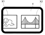
[表示例]
以下、表示部4に表示される対応画像を切り替える場合の表示の具体例(第1〜第4表示例)について、図面を参照して説明する。図7は、対応画像及び順番の一例を示す図である。図7に示す対応画像201の順番は1、対応画像202の順番は2、対応画像203の順番は3、対応画像204の順番は4、対応画像205の順番は5、対応画像206の順番は6、対応画像207の順番は7である。
[Display example]
Hereinafter, specific examples (first to fourth display examples) of display when the corresponding image displayed on the
また、対応画像203及び対応画像204は、相関関係が密接であると判定され得るものである。同様に、対応画像204及び対応画像205も、相関関係が密接であると判定され得るものである。そのため、対応画像203〜205は、相関関係が密接であると判定され得るものとなっている。なお、対応画像203〜205が対応するそれぞれの画像データが直接的に比較された結果、それぞれの対応画像203〜205は相関関係が密接であると判定され得るものであっても構わない。
Further, the
また、以下に説明する第1〜第4表示例では、特に言及することがない限り、対応画像201〜207の相関関係が密接であるか否かが、切替前(例えば、撮像時や転送時、詳細は後述)に予め求められているものとする。
In the first to fourth display examples described below, whether or not the correlation between the corresponding
{第1表示例}
図8は、第1表示例を示す図である。なお、図8に示す例は、図2に示す表示方法と同様の表示方法で対応画像を表示するものである。
{First display example}
FIG. 8 is a diagram illustrating a first display example. In the example shown in FIG. 8, the corresponding image is displayed by a display method similar to the display method shown in FIG.
図8(a)の状態では、対応画像201が前候補画像B20、対応画像202が再生候補画像C20、対応画像203が次候補画像A20となる。この状態から、図6に示す指示量Dの切替指示が順次入力されて、対応画像が順次送られる場合を想定し、以下説明する。
In the state of FIG. 8A, the
上述のように、対応画像202(再生候補画像C20)及び対応画像203(次候補画像A20)は、相関関係が密接でない。そのため、図8(a)の状態で指示量Dの切替指示が入力されると、図6に示す切替量E1,E2(本例では1とする)だけ対応画像が送られることになり、図8(b)の状態となる。図8(b)の状態とは、対応画像202が前候補画像B21、対応画像203が再生候補画像C21、対応画像204が次候補画像A21となる状態である。
As described above, the correspondence image 202 (reproduction candidate image C20) and the correspondence image 203 (next candidate image A20) are not closely correlated. Therefore, when an instruction to switch the instruction amount D is input in the state of FIG. 8A, the corresponding images are sent by the switching amounts E1 and E2 (1 in this example) shown in FIG. It will be in the state of 8 (b). The state in FIG. 8B is a state in which the
ここで、上述のように対応画像203(再生候補画像C21)、対応画像204(次候補画像A21)及び対応画像205は、相関関係が密接である。そのため、図8(b)の状態で指示量Dの切替指示が入力されると、図6に示す切替量ECだけ対応画像が切り替えられる。本例では切替量ECが、相関関係が密接である対応画像203〜205の全てが切り替えられる大きさ(本例では3)になるものとしている。
Here, as described above, the correspondence image 203 (reproduction candidate image C21), the correspondence image 204 (next candidate image A21), and the
この場合、図8(b)の状態から、図8(c)の状態を経て図8(d)の状態になる。図8(d)の状態とは、対応画像205が前候補画像B22、対応画像206が再生候補画像C22、対応画像207が次候補画像A22となる状態である。図8(c)の状態とは、図8(b)の状態から図8(d)の状態に至る経過状態であり、対応画像203が前候補画像、対応画像204が再生候補画像、対応画像205が次候補画像となる状態と、さらにその後に対応画像204が前候補画像、対応画像205が再生候補画像、対応画像206が次候補画像となる状態と、である。
In this case, the state of FIG. 8B is changed to the state of FIG. 8D through the state of FIG. 8C. The state of FIG. 8D is a state in which the
上記のように表示及び切替を行うこととすると、ユーザには、対応画像203〜205が高速で切り替えられたように見える。
If display and switching are performed as described above, it seems to the user that the corresponding
なお、本表示例において切替時に相関関係が密接であるか否かを判定する場合、計算量や計算速度などの都合上、再生候補画像と、順番がその前または後(戻す場合は前、送る場合は後)の数個分の対応画像と、の相関関係以外は判定することが困難となる場合がある。この場合、例えば、切替量ECを指示量Dに応じた値や所定の値としても構わない。また、事前に相関関係が密接であるか否かを判定する場合であっても、切替量ECを、指示量Dに応じた値や所定の値にしても構わない。 In this display example, when it is determined whether or not the correlation is close at the time of switching, the reproduction candidate images and the order are before or after (for the case of returning, before or after sending) for the convenience of calculation amount or calculation speed. In some cases, it may be difficult to make a determination other than the correlation with several corresponding images. In this case, for example, the switching amount EC may be a value corresponding to the instruction amount D or a predetermined value. Even when it is determined whether or not the correlation is close in advance, the switching amount EC may be a value corresponding to the instruction amount D or a predetermined value.
ところで、切替量ECを指示量Dに応じた値や所定の値とすると、相関関係が密接である対応画像203〜205の一部が一度に送られない(即ち、図8(c)のいずれかの状態で1回分の切替が終了する)状態が生じたり、再生候補画像C21(対応画像203)と相関関係が密接でない対応画像206や207までも一度に送られたりする状態が生じ得る。画像データの捜索上、後者の状態が生じると、対応画像の見落としが発生し得るため問題となる。しかしながら、切替量ECの値を、相関関係が密接であるか否かを判定することができる対応画像の数の範囲内として、かつ相関関係が密接であると判定された対応画像を全て切り替える値とすると、この問題となる状態が生じることを防止することができる。
By the way, when the switching amount EC is set to a value corresponding to the instruction amount D or a predetermined value, a part of the corresponding
{第2表示例}
図9は、第2表示例を示す図であり、第1表示例について示した図8に相当するものである。なお、図8と同様に図9に示す例も、図2に示す表示方法と同様の表示方法で対応画像を表示するものである。
{Second display example}
FIG. 9 is a diagram showing a second display example, and corresponds to FIG. 8 showing the first display example. As in FIG. 8, the example shown in FIG. 9 also displays the corresponding image by a display method similar to the display method shown in FIG.
図9(a)の状態では、対応画像201が前候補画像B30、対応画像202が再生候補画像C30となる。ただし、図9(a)の状態では、相関関係が密接である対応画像203〜205を重ねて1つにまとめた対応画像が、次候補画像A30となる。この状態から、図6に示す指示量Dの切替指示が順次入力されて、対応画像が順次送られる場合を想定し、以下説明する。
In the state of FIG. 9A, the
上述のように、対応画像202(再生候補画像C30)及び対応画像203〜205(次候補画像A20)は、相関関係が密接でない。そのため、図9(a)の状態で指示量Dの切替指示が入力されると、図6に示す切替量E1,E2(本例では1とする)だけ対応画像が送られることになり、図9(b)の状態となる。図9(b)の状態とは、対応画像202が前候補画像B31、対応画像203〜205を重ねて1つにまとめた対応画像が再生候補画像C31、対応画像206が次候補画像A31となる状態である。
As described above, the correspondence image 202 (reproduction candidate image C30) and the
ここで、上述のように対応画像203〜対応画像205(再生候補画像C31)は、相関関係が密接である。そのため、図9(b)の状態で指示量Dの切替指示が入力されると、図6に示す切替量ECだけ対応画像が切り替えられる。本例では、切替量ECが、相関関係が密接である対応画像203〜205の全てが切り替えられる大きさ(本例では3)になるものとしている。
Here, as described above, the
この場合、図9(b)の状態から、図9(c)の状態になる。図9(c)の状態とは、対応画像203〜205を重ねて1つにまとめた対応画像が前候補画像B32、対応画像206が再生候補画像C32、対応画像207が次候補画像A32となる状態である。
In this case, the state shown in FIG. 9B is changed to the state shown in FIG. In the state of FIG. 9C, the corresponding
上記のように表示及び切替を行うこととすると、ユーザには、対応画像203〜205がまとまって送られたように見える。
If display and switching are performed as described above, it appears to the user that the corresponding
本例では、対応画像203〜205を重ねて1つにまとめた対応画像中で、1つの代表対応画像(対応画像205)を他の対応画像と同様に表示する。代表対応画像として、対応顔図203〜205のいずれを用いても構わないが、本例では、順番が最後となる対応画像205を代表対応画像としている。例えば、順番を撮像時間順や撮像順にする場合、順番が最後となる画像データは、撮像者が満足した撮像により得られた画像データである可能性が高いため、失敗した撮像により得られた画像データである可能性が低い。そのため、順番が最後となる対応画像を代表対応画像にすることで、対応画像をサムネイル画像や縮小画像で構成する場合に、相関関係が密接である対応画像全体をユーザに把握させやすくすることが可能となる。
In the present example, one representative corresponding image (corresponding image 205) is displayed in the same manner as other corresponding images in the corresponding images obtained by overlapping the corresponding
なお、対応画像203〜205を重ねて1つにまとめた対応画像が、対応画像の切り替えの有無にかかわらず、常時まとまった状態で表示されることとしても構わないし、画像を切り替えないときに、それぞれの対応画像203〜205がまとまらずに分離して表示されることとしても構わない。
Note that the corresponding
{第3表示例}
図10は、第3表示例を示す図であり、第1及び第2表示例について示した図8及び図9に相当するものである。なお、図8及び図9と同様に図10に示す例も、図2に示す表示方法と同様の表示方法で対応画像を表示するものである。
{Third display example}
FIG. 10 is a diagram showing a third display example, and corresponds to FIGS. 8 and 9 showing the first and second display examples. 8 and 9, the corresponding image is displayed by the display method similar to the display method shown in FIG.
図10(a)の状態では、対応画像201が前候補画像B40、対応画像202が再生候補画像C40、対応画像203が次候補画像A40となる。この状態から、図6に示す指示量Dの切替指示が順次入力されて、対応画像が順次送られる場合を想定し、以下説明する。
In the state of FIG. 10A, the
上述のように、対応画像202(再生候補画像C40)及び対応画像203(次候補画像A40)は、相関関係が密接でない。そのため、図10(a)の状態で指示量Dの切替指示が入力されると、図6に示す切替量E1,E2(本例では1とする)だけ対応画像が送られることになり、図10(b)の状態となる。図10(b)の状態とは、対応画像202が前候補画像B41、対応画像204が再生候補画像C41、対応画像204及び205を組み合わせて1つにまとめた対応画像が次候補画像A41となる状態である。
As described above, the correspondence image 202 (reproduction candidate image C40) and the correspondence image 203 (next candidate image A40) are not closely correlated. Therefore, when an instruction to switch the instruction amount D is input in the state of FIG. 10A, the corresponding images are sent by the switching amounts E1 and E2 (in this example, 1) shown in FIG. 10 (b). In the state of FIG. 10B, the
ここで、上述のように対応画像203(再生候補画像C41)と、対応画像204及び205(次候補画像C41)とは、相関関係が密接である。そのため、図10(b)の状態で指示量Dの切替指示が入力されると、図6に示す切替量ECだけ対応画像が切り替えられる。本例では、切替量ECが、相関関係が密接である対応画像203〜205の全てが切り替えられる大きさ(本例では3)になるものとしている。
Here, as described above, the correspondence image 203 (reproduction candidate image C41) and the
この場合、図10(b)の状態から、図10(c)の状態を経て図10(d)の状態になる。図10(d)の状態とは、対応画像204及び205を組み合わせて1つにまとめた対応画像が前候補画像B42、対応画像206が再生候補画像C42、対応画像207が次候補画像A42となる状態である。図10(c)の状態とは、図10(b)の状態から図10(d)の状態に至る経過状態であり、対応画像203が前候補画像、対応画像204及び205を組み合わせて1つにまとめた対応画像が再生候補画像、対応画像206が次候補画像となる状態である。
In this case, the state of FIG. 10B is changed to the state of FIG. 10D through the state of FIG. 10C. In the state of FIG. 10D, the corresponding
上記のように表示及び切替を行うこととすると、ユーザには、対応画像203〜205がまとまって送られるように見える。
If display and switching are performed as described above, it appears to the user that the corresponding
本表示例では、相関関係が密接である対応画像203〜205の中で順番が最初である対応画像203をまとめずにそのまま表示し、対応画像204及び205は組み合わせて1つにまとめた対応画像として表示する。順番が最初である対応画像203をそのまま表示すると、1つにまとめられた対応画像が、先行する対応画像203に関連することをユーザに把握させやすくすることが可能となる。
In this display example, the corresponding
なお、対応画像204及び205を組み合わせて1つにまとめた対応画像が、対応画像の切り替えの有無にかかわらず、常時まとまった状態で表示されることとしても構わないし、画像を切り替えないときに、それぞれの対応画像204及び205がまとまらずに分離して表示されることとしても構わない。
It should be noted that the
また、上述の第2表示例と同様に、対応画像203〜205を組み合わせて1つの対応画像としても構わないし、対応画像204及び205を重ねて1つの対応画像としても構わない。また、まとめずにそのまま表示する対応画像を対応画像205として、対応画像203及び対応画像204を組み合わせて1つの対応画像としても構わない。
Similarly to the second display example described above, the corresponding
{第4表示例}
図11は、第4表示例を示す図であり、第1〜第3表示例について示した図8〜図10に相当するものである。なお、図8〜図10と同様に図11に示す例も、図2に示す表示方法と同様の表示方法で対応画像を表示するものである。
{Fourth display example}
FIG. 11 is a diagram showing a fourth display example, and corresponds to FIGS. 8 to 10 showing the first to third display examples. Note that the example shown in FIG. 11 as well as FIGS. 8 to 10 displays the corresponding image by the same display method as the display method shown in FIG.
図11(a)の状態では、対応画像201が前候補画像B50、対応画像202が再生候補画像C50となる。ただし、図11(a)の状態では、相関関係が密接である対応画像203〜205のいずれか1つを表示して(いずれか1つ以外の表示を省略して)1つにまとめた対応画像が、次候補画像A50となる。この状態から、図6に示す指示量Dの切替指示が順次入力されて、対応画像が順次送られる場合を想定し、以下説明する。
In the state of FIG. 11A, the
上述のように、対応画像202(再生候補画像C50)及び対応画像203〜205(次候補画像A50)は、相関関係が密接でない。そのため、図11(a)の状態で指示量Dの切替指示が入力されると、図6に示す切替量E1,E2(本例では1とする)だけ対応画像が送られることになり、図11(b)の状態となる。図11(b)の状態とは、対応画像202が前候補画像B51、対応画像203〜205のいずれか1つを表示して1つにまとめた対応画像が再生候補画像C51、対応画像206が次候補画像A51となる状態である。
As described above, the correspondence image 202 (reproduction candidate image C50) and the
ここで、上述のように対応画像203〜205(再生候補画像C31)は、相関関係が密接である。そのため、図11(b)の状態で指示量Dの切替指示が入力されると、図6に示す切替量ECだけ対応画像が切り替えられる。本例では、切替量ECが、相関関係が密接である対応画像203〜205の全てが切り替えられる大きさ(本例では3)になるものとしている。
Here, as described above, the
この場合、図11(b)の状態から、図11(c)の状態になる。図11(c)の状態とは、対応画像203〜205のいずれか1つを表示して1つにまとめた対応画像が前候補画像B52、対応画像206が再生候補画像C52、対応画像207が次候補画像A52となる状態である。
In this case, the state shown in FIG. 11B is changed to the state shown in FIG. In the state of FIG. 11C, the corresponding image 203-205 is displayed as one of the corresponding images and the corresponding image is the previous candidate image B52, the
上記のように表示及び切替を行うこととすると、ユーザには、対応画像203〜205がまとまって送られたように見える。
If display and switching are performed as described above, it appears to the user that the corresponding
本例では、対応画像203〜205のいずれか1つを表示して1つにまとめた対応画像中で、表示する1つの代表対応画像を、対応画像205としている。代表対応画像として、対応画像203〜205のいずれを用いても構わないが、第2表示例において述べたように、順番が最後となる対応画像を代表対応画像にすると、相関関係が密接である対応画像全体をユーザに把握させやすくすることが可能となる。
In this example, one representative corresponding image to be displayed among the corresponding images displayed by combining any one of the corresponding
また、本表示例の対応画像203〜205のいずれか1つを表示して1つにまとめた対応画像は、そのまま表示すると他の対応画像と区別することが困難となるため、何らかの方法で報知すると好ましい。例えば、図11に示すように他の対応画像よりも枠を太くして表示したり、枠の色やデザインを異ならせて表示したりすることで報知しても構わないし、アイコンなどを付加して表示することで報知しても構わない。
In addition, if any one of the corresponding
なお、対応画像203〜205のいずれか1つを表示して1つにまとめた対応画像が、対応画像の切り替えの有無にかかわらず、常時まとまった状態で表示されることとしても構わないし、画像を切り替えないときに、それぞれの対応画像203〜205がまとまらずに分離して表示されることとしても構わない。
It should be noted that any one of the corresponding
また、第4表示例に限らず、第1〜第3表示例においても、相関関係が密接である対応画像203〜205を直接的(第1表示例)または間接的(第2及び第3表示例)に表示する対応画像が、上述の報知を行うこととしても構わない。
Further, not only in the fourth display example, but also in the first to third display examples, the corresponding
<切替制御の変形例>
以下、相関関係が密接である対応画像を切り替える場合の切替制御の変形例について、図面を参照して説明する。図12は、切替制御の変形例について説明する指示量と切替量との関係の一例を示すグラフであり、基本関係について示した図3や、切替制御の一例について示した図6に相当するものである。
<Modification of switching control>
Hereinafter, a modification example of the switching control in the case of switching corresponding images having a close correlation will be described with reference to the drawings. FIG. 12 is a graph illustrating an example of the relationship between the instruction amount and the switching amount for explaining a modification example of the switching control, and corresponds to FIG. 3 illustrating the basic relationship and FIG. 6 illustrating the example of the switching control. It is.
図12(a)及び(b)に示すように、本変形例では、閾値Dth1以下となる指示量D1が入力されると、切り替えようとする対応画像の相関関係が密接であるか否かにかかわらず、基本関係に従った切替量E11,E21が設定される(換言すると、切替量ECが、切替量E11,E21に等しくなる)。 As shown in FIGS. 12A and 12B, in this modification, when the instruction amount D1 that is equal to or less than the threshold value Dth1 is input, whether or not the correlation between the corresponding images to be switched is close is determined. Regardless, the switching amounts E11 and E21 according to the basic relationship are set (in other words, the switching amount EC becomes equal to the switching amounts E11 and E21).
また、閾値Dth1より大きく、閾値Dth2より小さい指示量D2が入力されると、上述の図6に示した切替制御の一例と同様となる。即ち、切り替えようとする対応画像の相関関係が密接でなければ、基本関係に従って切替量E12,E22が設定され、切り替えようとする対応画像の相関関係が密接であれば、基本関係に従わずに切替量E12,E22以上となる切替量ECが設定される。 When an instruction amount D2 that is larger than the threshold value Dth1 and smaller than the threshold value Dth2 is input, the switching control is similar to the example of the switching control shown in FIG. That is, if the correlation between the corresponding images to be switched is not close, the switching amounts E12 and E22 are set according to the basic relationship. If the correlation between the corresponding images to be switched is close, the basic relationship is not followed. A switching amount EC that is greater than or equal to the switching amounts E12, E22 is set.
また、本変形例では、閾値Dth2以上となる指示量D3が入力されると、次のカテゴリの画像までジャンプすることとする。「カテゴリ」とは例えば、画像データの撮像日や撮像場所、撮像が行われたイベントなどが同一となるグループである。また「ジャンプ」とは、次のカテゴリに属する対応画像(例えば、カテゴリ内で順番が最初となる対応画像)まで切り替えることである。そのため、ジャンプをする場合、例えば現在の再生候補画像のカテゴリ内の順番(x)と、当該カテゴリに属する対応画像の数(y)と、に基づいた切替量(y−x+1)が設定される。 In this modification, when an instruction amount D3 that is equal to or greater than the threshold value Dth2 is input, a jump is made to an image of the next category. “Category” is, for example, a group in which the image data capturing date and image capturing location, the event in which the image capturing is performed, and the like are the same. The “jump” is to switch to a corresponding image belonging to the next category (for example, a corresponding image whose order is first in the category). Therefore, when jumping, for example, a switching amount (y−x + 1) based on the order (x) in the category of the current reproduction candidate image and the number of corresponding images (y) belonging to the category is set. .
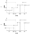
図12(a)及び(b)に示す指示量D1〜D3のそれぞれが表示制御部5に継続して入力される場合の対応画像の切替の具体例について、図面を参照して説明する。図13は、種々の指示量が入力されたときの対応画像の切替例を示す図である。
A specific example of switching of corresponding images when the instruction amounts D1 to D3 shown in FIGS. 12A and 12B are continuously input to the
図13に示す対応画像301の順番は1、対応画像302の順番は2、対応画像303の順番は3、対応画像304の順番は4、対応画像305の順番は5、対応画像306の順番は6、対応画像307の順番は7、対応画像308の順番は8である。また、対応画像304及び対応画像305、対応画像305及び対応画像306、対応画像306及び対応画像307、のそれぞれは相関関係が密接であると判定され得るものである。そのため、対応画像304〜307は相関関係が密接であると判定され得るものとなっている。なお、対応画像304〜307がそれぞれ対応する画像データが直接的に比較された結果、それぞれの対応画像304〜307の相関関係が密接であると判定され得るものであっても構わない。
The order of the
また、対応画像301及び302、対応画像303、対応画像304〜307、対応画像308は、それぞれ同じカテゴリに属するものとする。図13では、カテゴリを破線で示している。
The corresponding
また図13では、対応画像301を起点として、順番に沿って対応画像が切り替えられる状態を示している。ただし、説明の簡略化のため、図8〜図11とは異なり、1つの対応画像(例えば、再生候補画像)の切替(送り)のみに着目することとする。
FIG. 13 shows a state in which the corresponding images are switched in order from the
指示量D1が入力される場合、基本関係に従った切替量E11,E12が設定される。図13に示す例では、対応画像が1ずつ送られるものとしている(E11,E12=1)。そのため、指示量D1が入力される度(操作部3がユーザに操作される度)に、対応画像301から対応画像308まで1ずつ順番に送られる。
When the instruction amount D1 is input, switching amounts E11 and E12 according to the basic relationship are set. In the example shown in FIG. 13, it is assumed that corresponding images are sent one by one (E11, E12 = 1). Therefore, every time the instruction amount D1 is input (when the
このとき、対応画像304と、順番が対応画像304の後となる対応画像305と、は相関関係が密接であるが、上述の通り基本関係に従った切替量E11,E12が設定される。そのため、対応画像304,305は1ずつ送られることとなる(対応画像306,307が送られる場合も同様)。
At this time, the
指示量D2が入力されて対応画像301が送られる場合、対応画像301と、対応画像301の後となる対応画像302と、は相関関係が密接でないため、基本関係に従った切替量E12,E22が設定される(対応画像303が送られる場合も同様)。図13に示す例では、対応画像が2ずつ送られるものとしている(E21,E22=2)。
When the instruction amount D2 is input and the
一方、指示量D2が入力されて対応画像305が送られる場合、対応画像305と、順番が対応画像305の後となる対応画像306,307と、は相関関係が密接であるため、上述の通り基本関係に従わない切替量ECが設定される。図13に示す例では、上述した第1〜第4表示例と同様に、切替量ECが、相関関係が密接である対応画像305〜307の全てが送られる大きさ(本例では3)になるものとしている。
On the other hand, when the instruction amount D2 is input and the
指示量D3が入力される場合、対応画像がカテゴリ毎に送られる。特に、指示量D3が入力される度(操作部3がユーザに操作される度)に、次のカテゴリに属する対応画像のうち順番が最初である対応画像まで送られる。即ち、図13に示す例では、対応画像301,303,304,308の順に送られることとなる。
When the instruction amount D3 is input, a corresponding image is sent for each category. In particular, every time the instruction amount D3 is input (each time the
上述のように、閾値Dth1以下となる指示量D1が入力されるときに、切り替えようとする対応画像の相関関係が密接であるか否かにかかわらず、基本関係に従う切替量E11,E12を設定することとすると、相関関係が密接である対応画像304〜307のそれぞれを切り替える(例えば、再生候補画像にする)ことが可能となる。したがって、対応画像304〜307が対応するそれぞれの画像データの中に、選択すべき画像データが存在する場合でも、指示量を小さくする(例えば、ユーザが操作部3の一回当たりの(または単位時間当たりの)操作量を小さくしたり、一回当たりの操作時間を短くしたりする)だけで、容易に当該画像データを選択することが可能となる。
As described above, when the instruction amount D1 that is equal to or less than the threshold value Dth1 is input, the switching amounts E11 and E12 according to the basic relationship are set regardless of whether or not the correlation between the corresponding images to be switched is close. As a result, it is possible to switch each of the corresponding
また、閾値Dth2以上となる指示量D3が入力されるときに、対応画像をカテゴリ毎に切り替えることとすると、例えば捜索の初期において、選択すべき画像データの絞り込みを行うことが可能となる。そのため、画像データを容易かつ迅速に選択することが可能となる。 Further, if the corresponding image is switched for each category when the instruction amount D3 that is equal to or greater than the threshold value Dth2 is input, it is possible to narrow down the image data to be selected, for example, at the initial stage of the search. Therefore, it becomes possible to select image data easily and quickly.
なお、閾値Dth2を設けないこととしても構わない。このとき、閾値Dth1よりも大きい指示量が入力され、切り替えようとする対応画像の相関関係が密接でない場合であれば、基本関係に従う切替量が設定され、相関関係が密接である場合であれば、基本関係に従わない切替量ECが設定されることとしても構わない。 Note that the threshold value Dth2 may not be provided. At this time, if an instruction amount larger than the threshold value Dth1 is input and the correlation of the corresponding image to be switched is not close, a switching amount according to the basic relationship is set, and if the correlation is close The switching amount EC that does not follow the basic relationship may be set.
また、閾値Dth1,Dth2は、どのような値としても構わない。特に、図12(a)に示すように、階段状となる基本関係の段差部分と異なる値としても構わないし、図12(b)に示すように、階段状となる基本関係の段差部分と等しい値としても構わない。 Further, the threshold values Dth1 and Dth2 may be any value. In particular, as shown in FIG. 12 (a), the value may be different from the step portion of the basic relationship having a staircase shape, and is equal to the step portion of the basic relationship having a staircase shape as shown in FIG. 12 (b). It does not matter as a value.
また、上述の第2〜第4表示例にも、本変形例は適用され得る。この場合例えば、少なくとも閾値Dth1以下となる指示量が入力されるときは、1つにまとまっていた対応画像がそれぞれの対応画像に分離されて、それぞれ表示及び切替が行われることとしても構わない。 The present modification can also be applied to the second to fourth display examples described above. In this case, for example, when an instruction amount that is at least equal to or less than the threshold value Dth1 is input, the corresponding images that are grouped into one may be separated into the corresponding images and displayed and switched, respectively.
<相関の有無を求めるタイミング>
次に、上述した対応画像の相関関係が密接であるか否かを判定するタイミングについて、図面を参照して説明する。
<Timing for determining the presence of correlation>
Next, timing for determining whether or not the correlation between the corresponding images described above is close will be described with reference to the drawings.
[切替時]
図14は、対応画像の切替時に相関関係が密接であるか否かを判定して対応画像の切替を行う場合の動作を示すフローチャートである。図14に示す動作は、例えば画像表示装置1において画像データを再生しようとする場合に行われる動作であり、ユーザが操作部3を1回操作する際に行われるものである。
[When switching]
FIG. 14 is a flowchart showing an operation in a case where it is determined whether or not the correlation is close when the corresponding image is switched and the corresponding image is switched. The operation illustrated in FIG. 14 is performed when, for example, the
図14に示すように、最初に、ユーザが操作部3を操作することにより、画像表示装置1に切替指示が入力される(STEP1)。このとき、表示制御部5が上述した指示量を確認する。また、表示制御部5は、切替前の対応画像(例えば、STEP1の時点での再生候補画像、または、STEP2の時点での再生候補画像)と、当該対応画像よりも順番が前または後となる切替候補の対応画像(例えば、STEP2の時点での前候補画像または次候補画像)と、の相関関係が密接であるか否かを判定する(STEP2)。
As illustrated in FIG. 14, first, when the user operates the
表示制御部5は、指示量とSTEP2の判定結果とに基づいて、切替前の対応画像を切替候補の対応画像に切り替えるべきか否かを決定する(STEP3)。この切替の適否の決定は、切替候補の対応画像に切り替えた場合に、上述した切替量の範囲内になるか否かに基づいて決定することができる。具体的には、対応画像を切り替えたとしても切替量の範囲内になるのであれば、対応画像を切り替えると決定する。
The
ところで、上述のように計算量や計算速度などの都合上、相関関係が密接であるか否かを判定することができる対応画像の数が限られている場合がある。この場合、STEP3では、相関関係が密接であるか否かを判定することができるか否か(さらにSTEP2を行うことができるか否か)に基づいた切替量が設定され、切替の適否の決定が行われる。
By the way, as described above, there are cases where the number of corresponding images that can determine whether or not the correlation is close is limited for the convenience of calculation amount and calculation speed. In this case, in
対応画像を切り替えないと決定する場合は(STEP3、NO)、切替を終了する。一方、切替候補の対応画像を切り替えると決定する場合は(STEP3、YES)、切替前の対応画像を切替候補の対応画像に切り替える(STEP4)。この対応画像は、例えば、上述の第1表示例のように高速で切り替えられる。そして、STEP4で対応画像が切り替えられるとSTEP2に戻り、以下STEP3、STEP4で同様の動作が行われる。
When it is determined that the corresponding image is not switched (
以上のように、切替時に対応画像(画像データ)の相関関係が密接であるか否かを判定することとすると、どのような対応画像(例えば、複数の撮像装置で撮像された画像データや、順番などの各種情報が変更された画像データ)であっても、上述の切替制御を行うことが可能となる。 As described above, when it is determined whether or not the correlation between the corresponding images (image data) is close at the time of switching, what kind of corresponding images (for example, image data captured by a plurality of imaging devices, The above switching control can be performed even for image data in which various types of information such as the order are changed.
[転送時]
図15は、画像データの転送時に相関関係が密接であるか否かを判定する場合の動作を示すフローチャートである。図15に示す動作は、例えば、撮像により得られた画像データが、撮像装置からビューア(画像表示装置1)や記録装置に転送される場合に行われるものである。
[When transferring]
FIG. 15 is a flowchart showing an operation in the case of determining whether or not the correlation is close when transferring image data. The operation illustrated in FIG. 15 is performed, for example, when image data obtained by imaging is transferred from the imaging device to a viewer (image display device 1) or a recording device.
図15に示すように、最初に、転送される画像データを指定する転送指示が入力される(STEP11)。そして、転送される画像データの有無が確認される(STEP12)。転送される画像データがなければ(STEP12、NO)、転送を終了する。一方、転送される画像データがあれば(STEP12、YES)、転送される画像データと、順番が当該画像データの前後となる画像データと、の相関関係が密接であるか否かを判定する(STEP13)。 As shown in FIG. 15, first, a transfer instruction specifying image data to be transferred is input (STEP 11). Then, the presence or absence of image data to be transferred is confirmed (STEP 12). If there is no image data to be transferred (STEP 12, NO), the transfer ends. On the other hand, if there is image data to be transferred (STEP 12, YES), it is determined whether or not there is a close correlation between the image data to be transferred and the image data whose order is before and after the image data ( (STEP 13).
ここで、転送される画像データと、その前または後の画像データとの相関関係が密接である場合(STEP14、YES)、画像表示装置や記録装置に、相関関係が密接である画像データとして記録される(STEP15)。このとき、相関関係が密接であることを示す情報を画像データの一部であるヘッダなどに記録しても構わないし、画像表示装置や記録装置のシステムの記録領域に記録しても構わない。 Here, when the correlation between the transferred image data and the previous or subsequent image data is close (STEP 14, YES), the image data is recorded as close-correlated image data on the image display device or the recording device. (STEP 15). At this time, information indicating that the correlation is close may be recorded in a header which is a part of the image data, or may be recorded in a recording area of the system of the image display apparatus or the recording apparatus.
一方、転送される画像データと、その前または後の画像データとの相関関係が密接でない場合(STEP14、NO)、画像表示装置や記録装置に、相関関係が密接でない画像データとして記録される(STEP16)。このとき、STEP15と同様に相関関係が密接でないことを示す情報をヘッダやシステム領域に記録しても構わないし、相関関係について記録しないことで相関関係が密接でないことを示しても構わない。 On the other hand, when the correlation between the transferred image data and the previous or subsequent image data is not close (STEP 14, NO), the image data is recorded as incompletely related image data on the image display device or the recording device ( (STEP 16). At this time, as in STEP 15, information indicating that the correlation is not close may be recorded in the header or the system area, or by not recording the correlation, it may be indicated that the correlation is not close.
STEP15またはSTEP16が終了すると、STEP12に戻り他の画像データが転送されるか否かを確認し、以下同様の動作を行う。 When STEP 15 or STEP 16 ends, the process returns to STEP 12 to check whether other image data is transferred, and thereafter the same operation is performed.
このように構成すると、画像表示装置1で画像データを再生しようとする際に、予め画像データの相関関係が密接であるか否かが判定されていることになる。したがって、切替時に相関関係が密接であるか否かを判定する必要がなくなるため、上述の切替制御を迅速に行うことが可能となる。
With this configuration, when image data is to be reproduced on the
なお、STEP15及び16において、相関関係が密接であることを示す情報を記録することとしたが、相関度を記録することとしても構わない。また、相関関係が密接であるか否かの判定は、撮像装置が行うこととしても構わないし、画像表示装置や記録装置が行うこととしても構わない。 In STEPs 15 and 16, information indicating that the correlation is close is recorded, but the degree of correlation may be recorded. Further, the determination of whether or not the correlation is close may be performed by the imaging device, or may be performed by the image display device or the recording device.
[撮像時]
図16は、撮像時に相関関係が密接であるか否かを判定する場合の動作を示すフローチャートである。図16に示す動作は、一つの画像データを撮像により得る場合に行われる動作である。
[When imaging]
FIG. 16 is a flowchart showing an operation when it is determined whether or not the correlation is close during imaging. The operation shown in FIG. 16 is an operation performed when one piece of image data is obtained by imaging.
図16に示すように、最初に、画像データの撮像を行う(STEP21)。そしてSTEP21の撮像により得られた画像データと、順番が当該画像データの前となる画像データと、の相関関係が密接であるか否かを判定する(STEP22)。なお、順番が当該画像データの後となる画像データが存在する場合は、当該画像データと後の画像データとの相関関係が密接であるか否かを判定しても構わない。 As shown in FIG. 16, first, image data is captured (STEP 21). Then, it is determined whether or not there is a close correlation between the image data obtained by the imaging in STEP 21 and the image data whose order precedes the image data (STEP 22). When there is image data whose order is after the image data, it may be determined whether or not the correlation between the image data and the subsequent image data is close.
ここで、撮像により得られた画像データと、順番が前(または後)となる画像データとの相関関係が密接である場合(STEP23、YES)、相関関係が密接である画像データとして撮像装置の記録部に記録される(STEP24)。このとき、相関関係が密接であることを示す情報を画像データの一部であるヘッダなどに記録しても構わないし、撮像装置のシステムの記録領域に記録しても構わない。 Here, when the correlation between the image data obtained by imaging and the image data with the previous (or subsequent) order is close (STEP 23, YES), the image data of the imaging apparatus is used as image data with a close correlation. It is recorded in the recording unit (STEP 24). At this time, information indicating that the correlation is close may be recorded in a header which is a part of the image data, or may be recorded in a recording area of the system of the imaging apparatus.
一方、撮像により得られた画像データと、順番が前(または後)となる画像データとの相関関係が密接でない場合(STEP23、NO)、相関関係が密接でない画像データとして撮像装置の記録部に記録される(STEP25)。このとき、STEP24と同様に相関関係が密接でないことを示す情報をヘッダやシステムの記録領域に記録しても構わないし、相関関係について記録しないことで相関関係が密接でないことを示しても構わない。そして、STEP24またはSTEP25が終了することにより、動作を終了する。 On the other hand, when the correlation between the image data obtained by imaging and the image data whose order is before (or after) is not close (STEP 23, NO), the image data is not closely related to the recording unit of the imaging device. It is recorded (STEP 25). At this time, as in STEP 24, information indicating that the correlation is not close may be recorded in the header or the recording area of the system, or it may be indicated that the correlation is not close by not recording the correlation. . Then, when STEP 24 or STEP 25 ends, the operation ends.
このように構成すると、上述の[転送時]と同様に、画像表示装置1で画像データを再生しようとする際に、予め相関関係が密接であるか否かが判定されていることになる。したがって、切替時に相関関係が密接であるか否かを判定する必要がなくなるため、上述の切替制御を迅速に行うことが可能となる。
With this configuration, as in the above [during transfer], when image data is to be reproduced on the
なお、STEP24及び25において、相関関係が密接であることを示す情報を記録することとしたが、相関度を記録することとしても構わない。 In STEPs 24 and 25, information indicating that the correlation is close is recorded, but the degree of correlation may be recorded.
[相関関係が密接であるか否か予め判定されている対応画像の切替]
次に、上述の[転送時]や[撮像時]に記録したような、相関関係が密接であるか否かが予め判定されている対応画像の切替動作について、図面を参照して説明する。図17は、相関関係が密接であるか否かが予め判定されている場合の対応画像の切替動作を示すフローチャートである。図17に示す動作は、例えば画像表示装置1において画像データを再生しようとする場合に行われる動作であり、ユーザが操作部3を1回操作する際に行われるものである。
[Switching of Corresponding Images Preliminarily Determining Whether Correlation is Close]
Next, the switching operation of the corresponding image in which it is determined in advance whether or not the correlation is close as recorded in the above-mentioned [during transfer] and [during imaging] will be described with reference to the drawings. FIG. 17 is a flowchart showing a corresponding image switching operation when it is determined in advance whether or not the correlation is close. The operation shown in FIG. 17 is an operation performed when, for example, image data is to be reproduced in the
図17に示すように、最初に、ユーザが操作部3を操作することにより、画像表示装置1に切替指示が入力される(STEP31)。このとき、表示制御部5が上述した指示量を確認する。また、表示制御部5は、切替前の対応画像(例えば、STEP31の時点での再生候補画像、または、STEP32の時点での再生候補画像)と、当該対応画像よりも順番が前または後となる切替候補の対応画像(例えば、STEP2の時点での前候補画像または次候補画像)と、の相関関係が密接であるか否かを確認する(STEP32)。
As shown in FIG. 17, first, when the user operates the
表示制御部5は、指示量とSTEP32で確認した相関関係とに基づいて、切替前の対応画像を切替候補の対応画像に切り替えるべきか否かを決定する(STEP33)。この切替の適否の決定は、切替候補の対応画像を切り替えた場合に、上述した切替量の範囲内になるか否かに基づいて決定することができる。具体的には、切替候補の対応画像に切り替えたとしても切替量の範囲内になるのであれば、対応画像を切り替えると決定する。
The
対応画像を切り替えないと決定する場合は(STEP33、NO)、切替を終了する。一方、対応画像を切り替えると決定する場合は(STEP33、YES)、切替前の対応画像を切替候補の対応画像に切り替える(STEP34)。この対応画像は、例えば、上述の第1表示例のように高速で切り替えられたり、第2〜第4表示例のように他の対応画像とまとめて切り替えられたりする。そして、STEP34で対応画像が切り替えられるとSTEP32に戻り、以下STEP33、STEP34で同様の動作が行われる。 When it is determined that the corresponding image is not switched (STEP 33, NO), the switching is ended. On the other hand, when it is determined that the corresponding image is to be switched (STEP 33, YES), the corresponding image before switching is switched to the corresponding candidate image for switching (STEP 34). For example, the corresponding image is switched at high speed as in the first display example described above, or is switched together with other corresponding images as in the second to fourth display examples. When the corresponding image is switched in STEP 34, the process returns to STEP 32, and the same operation is performed in STEP 33 and STEP 34.
以上のように、対応画像の相関関係が密接であるか否かが予め判定されていると、切替時に相関関係を確認するだけで済むようになる。そのため、画像表示装置1の切替制御の迅速化や、構成の簡略化を図ることが可能となる。
As described above, if it is determined in advance whether or not the correlation between the corresponding images is close, it is only necessary to confirm the correlation at the time of switching. Therefore, it is possible to speed up the switching control of the
<複合対応画像をユーザが選択する場合の動作例>
上述の説明では、ユーザが対応画像を選択する(操作部3を介して選択指示を入力する)場合、当該対応画像が対応する画像データを再生するものとした。しかしながら、少なくとも2つの対応画像がまとめられて成る1つの対応画像(第2〜第4表示例、図7及び図9〜11参照。以下、複合対応画像と表現して、単体の対応画像と区別する。)を、ユーザが選択する場合がある。この場合、ユーザが対応画像を選択する場合とは異なる動作をするように構成すると、好ましい。
<Operation example when user selects composite compatible image>
In the above description, when the user selects a corresponding image (inputs a selection instruction via the operation unit 3), the image data corresponding to the corresponding image is reproduced. However, one corresponding image formed by aggregating at least two corresponding images (see second to fourth display examples, FIG. 7 and FIGS. 9 to 11). May be selected by the user. In this case, it is preferable that the operation is different from that performed when the user selects the corresponding image.
そこで、ユーザが複合対応画像を選択する場合の動作例について、以下説明する。なお、以下に示す各動作例は、同種のもの及び異種のものを問わず、矛盾なき限り組み合わせて実施可能である。また、主に第2表示例(図9参照)や第3表示例(図10参照)に各動作例を適用する場合について例示し、第4表示例(図11参照)に各動作例を適用する場合は第2表示例に各動作例を適用する場合と同様として、その説明を省略する。また、説明の簡略化のため、以下の各動作例の説明において図面を参照する場合、図7、図9及び図10と同様の部分については同様の符号を付して、その詳細な説明を省略する。 An example of operation when the user selects a composite-compatible image will be described below. Note that the following operation examples can be implemented in combination as long as there is no contradiction, regardless of whether they are the same type or different types. Moreover, the case where each operation example is applied to the second display example (see FIG. 9) and the third display example (see FIG. 10) is mainly illustrated, and each operation example is applied to the fourth display example (see FIG. 11). In this case, the description is omitted as in the case of applying each operation example to the second display example. For simplification of description, when the drawings are referred to in the following description of each operation example, the same reference numerals are given to the same parts as those in FIGS. Omitted.
[複合対応画像の選択検出動作]
最初に、複合対応画像がユーザによって選択されたことを表示制御部5が検出する各動作例について、図面を参照して説明する。
[Selection detection operation for composite images]
First, each operation example in which the
{選択検出動作:第1例}
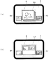
図18は、複合対応画像の選択検出動作の第1例を示す図であり、図18(a)が第2表示例に対応し、図18(b)が第3表示例に対応する。図18(a),(b)に示すように、本動作例は、選択検出範囲Sに複合対応画像が位置し、操作部3を介したユーザの指示が所定の時間以上入力されないときに、複合対応画像が選択されたことを表示制御部5が検出する。具体的に例えば、複合対応画像が再生候補画像C6,C7となり、ユーザから切替指示が所定の時間以上入力されない場合に、複合対応画像が選択されたことを表示制御部5が検出する。
{Selection detection operation: first example}
FIG. 18 is a diagram illustrating a first example of the composite detection image selection detection operation. FIG. 18A corresponds to the second display example, and FIG. 18B corresponds to the third display example. As shown in FIGS. 18A and 18B, in this operation example, when the composite corresponding image is located in the selection detection range S and the user's instruction via the
なお、選択検出範囲Sは、再生候補画像の位置に限らず、前候補画像や次候補画像位置に設定しても構わない。また、1つの位置に限らず複数の位置に設定しても構わない。例えば、前候補画像、再生候補画像及び次候補画像のそれぞれの位置に設定しても構わないし、いずれか2つの位置に設定しても構わない。 The selection detection range S is not limited to the position of the reproduction candidate image, and may be set to the previous candidate image or the next candidate image position. Moreover, you may set not only one position but in several positions. For example, it may be set at each position of the previous candidate image, the reproduction candidate image, and the next candidate image, or may be set at any two positions.
また、本動作例における、選択検出範囲Sに複合対応画像が位置して操作部3を介したユーザの指示が所定の時間以上入力されない状態は、後述する複合対応画像の選択後動作の第4例における同様の状態と、共通化することができる。
Further, in this operation example, the state in which the composite corresponding image is located in the selection detection range S and the user's instruction via the
{選択検出動作:第2例}
図19は、複合対応画像の選択検出動作の第2例を示す図であり、図19(a)が第2表示例に対応し、図19(b)が第3表示例に対応する。図19(a),(b)に示すように、本動作例は、操作部3を介してユーザから複合対応画像を選択する選択指示が入力される場合に、表示制御部5が、複合対応画像が選択されたことを検出する。具体的に例えば、複合対応画像(図19(a)の再生候補画像C8、図19(b)の次候補画像A9)を選択する選択指示が入力された場合に、複合対応画像が選択されたことを表示制御部5が検出する。
{Selection detection operation: second example}
FIG. 19 is a diagram illustrating a second example of the composite-corresponding image selection detection operation. FIG. 19A corresponds to the second display example, and FIG. 19B corresponds to the third display example. As shown in FIGS. 19A and 19B, in this operation example, when a selection instruction for selecting a composite corresponding image is input from the user via the
{選択検出動作:第3例}
本動作例は、選択検出動作の第1例で述べた選択検出範囲S(図18参照)に複合対応画像が位置しているときに、操作部3を介してユーザから切替指示とは異なる指示が入力されたときに、表示制御部5が、複合対応画像が選択されたことを検出する。
{Selection detection operation: third example}
This operation example is an instruction different from the switching instruction from the user via the
具体的に例えば、複合対応画像が再生候補画像C6となり、切替指示を入力する際にユーザが操作部3を操作する方向(以下、切替指示方向とする)とは異なる方向(例えば、切替指示方向に対して垂直となる方向や、当該方向と切替指示方向との間となる方向。以下、非切替指示方向とする。)の操作をユーザが行う場合に、複合対応画像が選択されたことを表示制御部5が検出する。
Specifically, for example, the composite corresponding image becomes the reproduction candidate image C6, and a direction (for example, a switching instruction direction) different from a direction (hereinafter referred to as a switching instruction direction) in which the user operates the
ユーザが操作部3を非切替指示方向に操作するとは、例えば、操作部3がタッチパネルであり、表示部4中で前候補画像B6,B7、再生候補画像C6,C7及び次候補画像A6,A7が整列する方向(図中の左右方向、切替指示方向)にスライドする(なぞる)ことで切替指示が入力される場合では、ユーザが切替指示方向とは異なる方向(図中の上下方向や斜め方向、即ち、非切替指示方向)に沿って表示部4上をスライドする(なぞる)ことである。また例えば、操作部3がトラックボールやキーであり、上記の整列方向(切替指示方向)に沿ってトラックボールを転がしたり、当該方向に対応するキーを押下したりすることで切替指示が入力される場合では、ユーザが切替指示方向とは異なる方向(非切替指示方向)に沿ってトラックボールを転がしたり、当該方向に対応するキーを押下することである。
When the user operates the
なお、本動作例における切替指示とは異なる指示は、後述する複合対応画像の選択後動作の第3例における同様の指示と、共通化することができる。 Note that an instruction different from the switching instruction in this operation example can be shared with the same instruction in the third example of the post-selection operation of the composite corresponding image described later.
また、上述の選択検出動作の第1例〜第3例は、複合対応画像を選択する場合に限らず、対応画像を選択する場合にも適用可能である。 Further, the first to third examples of the selection detection operation described above are not limited to the case of selecting a composite corresponding image, but can be applied to the case of selecting a corresponding image.
[複合対応画像の選択後動作]
次に、複合対応画像がユーザによって選択された後に表示制御部5が行う各動作例について、図面を参照して説明する。
[Operation after selecting a composite image]
Next, each operation example performed by the
{選択後動作:第1例}
図20は、複合対応画像の選択後動作の第1例を示す図であり、第2表示例に対応するものである。図20(a)は、選択検出動作を行う前の表示例である。図20(b)は、選択検出動作直後の表示例である。図20(c)は、表示部4が図20(b)の状態であるときに、ユーザが操作部3を介して切替指示とは異なる指示を入力した場合の表示例である。
{Operation after selection: first example}
FIG. 20 is a diagram illustrating a first example of the operation after selecting a composite-compatible image, and corresponds to the second display example. FIG. 20A is a display example before the selection detection operation is performed. FIG. 20B is a display example immediately after the selection detection operation. FIG. 20C is a display example when the user inputs an instruction different from the switching instruction via the
図20(a),(b)に示すように、本動作例では、表示制御部5が上述の選択検出動作を行うと、複合対応画像を成すいずれかの対応画像が対応する画像データを表示部4に再生させる。このとき、例えば複合対応画像中の代表対応画像205(図7参照)が対応する画像データを、再生しても構わない。
As shown in FIGS. 20A and 20B, in this operation example, when the
そして、図20(b)に示すように画像データが再生されている状態で、ユーザが操作部3を介して切替指示とは異なる指示を入力すると、表示制御部5は、再生している画像データとは異なり、かつ、選択した複合対応画像に含まれるいずれかの対応画像が対応する画像データを、表示部4に再生させる。なお、図20(c)では、対応画像203(図7参照)が対応する画像データが表示部4で再生される場合を例示している。
When the user inputs an instruction different from the switching instruction via the
そして、ユーザが、切替指示とは異なる指示をさらに入力する(例えば、ユーザが操作部3に対して非切替指示方向の操作を行う)と、表示制御部5は、表示部4で再生する画像データを順次変更する。例えば、上述した相関度の順や、画像の類似度の順、撮像日時などの順に、再生する画像データを変更する。
When the user further inputs an instruction different from the switching instruction (for example, the user performs an operation in the non-switching instruction direction on the operation unit 3), the
このように構成すると、相関関係が密接である複数の対応画像が対応するそれぞれの画像データを、ユーザが容易に再生して確認することが可能となる。 If comprised in this way, it will become possible for a user to reproduce | regenerate and confirm each image data with which the some corresponding | compatible image with close correlation respond | corresponds easily.
なお、ユーザが操作部3に対して非切替指示方向の操作を行うことで、表示部4で再生される画像データが変更される場合、操作方向によって(例えば、上方向か下方向かによって、または、斜め上方向か斜め下方向かによって)、所定の順番に沿った変更が行われることとしても構わない。具体的に例えば、ユーザが上方向の操作を行うと、表示部4に再生される画像データが昇順に変更され、ユーザが下方向の操作を行うと、表示部4に再生される画像データが降順に変更されることとしても構わない。このように構成すると、ユーザが所望の画像データを容易に探索することが可能になる。
In addition, when the image data reproduced | regenerated by the
また、操作方向によって、順番の指標(例えば、撮像日時や、画像データが示す画像の類似度など)が異なる変更が行われることとしても構わない。具体的に例えば、ユーザが上方向の操作を行うと、撮像日時の順に表示部4で再生される画像データが変更され、ユーザが下方向の操作を行うと、画像の類似度の順に表示部4で再生される画像データが変更されることとしても構わない。このように構成すると、ユーザが所望の画像データを探索する際に、任意の指標を選択することが可能になる。
In addition, changes in order indices (for example, imaging date and time, similarity of images indicated by image data, and the like) may be changed depending on the operation direction. Specifically, for example, when the user performs an upward operation, the image data reproduced on the
また、ユーザが操作部3の操作方向の種類(例えば、上下方向及び斜め方向)を異ならせることで、表示部4で再生される画像データを複数の方法で変更可能としても構わない。具体的に例えば、ユーザが上下方向の操作をすることで、所定の順番に沿った変更が行われ、斜め方向の操作をすることで、順番の指標を異ならせた変更が行われることとしても構わない。
Further, the user may change the type of operation direction of the operation unit 3 (for example, the vertical direction and the oblique direction) so that the image data reproduced on the
また、操作方向の種類に応じて順番の指標が異なり、操作方向に応じて当該順番の昇降が制御されることとしても構わない。具体的に例えば、ユーザが上方向の操作をすると、撮像日時の昇順に表示部4で再生される画像データが変更され、ユーザが下方向の操作を行うと、撮像日時の降順に表示部4で再生される画像データが変更され、ユーザが斜め上方向の操作をすると、画像の類似度の昇順に表示部4で再生される画像データが変更され、ユーザが斜め下方向の操作を行うと、画像の類似度の降順に表示部4で再生される画像データが変更されることとしても構わない。
Further, the order index may be different depending on the type of operation direction, and the raising / lowering of the order may be controlled according to the operation direction. Specifically, for example, when the user performs an upward operation, the image data reproduced on the
また、第3表示例に本動作例を適用する場合、上記の第2表示例に適用する場合と同様の動作が行われることとしても構わない。このとき、複合対応画像を成す対応画像204,205(図7及び図10参照)が対応する画像データが、表示部4で再生され得るようにしても構わない。また、相関関係が密接である対応画像203〜205(図7及び図10参照)が、表示部4で再生され得るようにしても構わない。
Further, when the present operation example is applied to the third display example, the same operation as that applied to the second display example may be performed. At this time, the image data corresponding to the corresponding
{選択後動作:第2例}
本動作例では、表示部4が選択後動作の第1例と同様の動作を行う(図20参照)が、表示制御部5が、表示部4で再生する画像データを変更する動作(図20(b)から図20(c)へ変更する動作)が、第1例と本動作例とで異なる。なお、本動作例において、上記以外の動作は第1例と同様であるため、説明を省略する。
{Operation after selection: second example}
In this operation example, the
本動作例では、表示制御部5が、操作部3を介したユーザの指示が所定の時間以上入力されないことを検出することで、表示部4で再生する画像データを所定の順番に沿って変更する。また、表示制御部5は、当該変更を繰り返し行い得る。
In this operation example, the
このように構成すると、相関関係が密接である複数の対応画像が対応するそれぞれの画像データを、ユーザが特別な操作をすることなく容易に再生して確認することが可能となる。 If comprised in this way, it will become possible to reproduce | regenerate and confirm each image data which the some corresponding | compatible image with close correlation respond | corresponds easily, without a user performing special operation.
{選択後動作:第3例}
図21は、複合対応画像の選択後動作の第3例を示す図であり、第2表示例に対応するものである。図21(a)は、選択検出動作を行う前の表示例である。図21(b)は、選択検出動作直後の表示例である。図21(c)は、表示部4が図21(b)の状態であるときに、ユーザが操作部3を介して切替指示とは異なる指示を入力した場合の表示例である。
{Operation after selection: third example}
FIG. 21 is a diagram illustrating a third example of the post-selection operation of the composite-compatible image, and corresponds to the second display example. FIG. 21A is a display example before the selection detection operation is performed. FIG. 21B is a display example immediately after the selection detection operation. FIG. 21C is a display example when the user inputs an instruction different from the switching instruction via the
図21(a),(b)に示すように、本動作例では表示制御部5が上述の選択検出動作を行っても、複合対応画像の表示を継続する。このとき、前候補画像B112や次候補画像A112の少なくとも一部が表示される範囲内であれば(即ち、ユーザが複合対応画像及び対応画像の順番を把握可能な状態であれば)、複合対応画像を拡大するなど、各種調整を行っても構わない。
As shown in FIGS. 21A and 21B, in this operation example, even when the
そして、図21(b)に示すように複合対応画像が表示されている状態で、ユーザが操作部3を介して切替指示とは異なる指示を入力すると、表示制御部5は、複合対応画像中の代表対応画像205(図7参照)とは異なり、かつ、選択した複合対応画像に含まれるいずれかの対応画像が代表対応画像になるように、表示部4の表示状態を変更する。なお、図21(c)では、対応画像203(図7参照)が代表対応画像になるように、表示部4の表示状態が変更される場合を例示している。
When the user inputs an instruction different from the switching instruction via the
そして、ユーザが、切替指示とは異なる指示をさらに入力すると、表示制御部5は、複合対応画像中の代表対応画像を順次変更する。例えば、上述した相関度の順や、画像の類似度の順、撮像日時などの順に、代表対応画像を変更する。
When the user further inputs an instruction different from the switching instruction, the
このように構成すると、複合対応画像を成す複数の対応画像を、ユーザが容易に確認することが可能となる。 If comprised in this way, it will become possible for a user to confirm the some corresponding | compatible image which comprises a composite corresponding | compatible image easily.
なお、選択後動作の第1例において、ユーザが操作部3に対して非切替指示方向の操作を行うことで、表示部4で再生される画像データが変更される動作について述べたが、当該動作を本動作例で行っても構わない。ただし、本動作例では、複合対応画像中の代表対応画像が変更されるものとする。
In the first example of the post-selection operation, the operation in which the image data reproduced on the
また、第3表示例に本動作例を適用する場合、上記の第2表示例に適用する場合と同様の動作が行われることとしても構わない。このとき、複合対応画像を成す対応画像204,205(図7及び図10参照)の表示部4での表示状態(例えば、並び順や大きさ)が変更され得るようにしても構わない。また、相関関係が密接である対応画像203〜205(図7及び図10参照)において、まとめられずに表示される対応画像203と、複合対応画像を成す対応画像204,205とが入れ替えられることで、まとめられずに表示される対応画像が変更され得るようにしても構わない。
Further, when the present operation example is applied to the third display example, the same operation as that applied to the second display example may be performed. At this time, the display state (for example, arrangement order and size) of the corresponding
{選択後動作:第4例}
本動作例では、表示部4が選択後動作の第3例と同様の動作を行う(図21参照)が、表示制御部5が、複合対応画像中の代表対応画像を変更する動作(図21(b)から図21(c)へ変更する動作)が、第3例と本動作例とで異なる。なお、本動作例において、上記以外の動作は第3例と同様であるため、説明を省略する。
{Operation after selection: 4th example}
In this operation example, the
本動作例では、表示制御部5が、操作部3を介したユーザの指示が所定の時間以上入力されないことを検出することで、複合対応画像中の代表対応画像を、所定の順番に沿って変更する。また、表示制御部5は、当該変更を繰り返し行い得る。
In this operation example, the
このように構成すると、複合対応画像を成す複数の対応画像を、ユーザが特別な操作をすることなく容易に確認することが可能となる。 If comprised in this way, it will become possible to confirm easily the some corresponding | compatible image which comprises a composite corresponding | compatible image, without a user performing special operation.
{選択後動作:第5例}
図22は、複合対応画像の選択後動作の第5例を示す図であり、第2表示例に対応するものである。図22(a)は、選択検出動作を行う前の表示例である。図22(b)は、選択検出動作直後の表示例である。図22(c)は、表示部4が図22(b)の状態であるときに、ユーザが操作部3を介して選択指示を入力した場合の表示例である。
{Operation after selection: fifth example}
FIG. 22 is a diagram illustrating a fifth example of the operation after selection of the composite-compatible image, and corresponds to the second display example. FIG. 22A is a display example before the selection detection operation is performed. FIG. 22B is a display example immediately after the selection detection operation. FIG. 22C is a display example when the user inputs a selection instruction via the
図22(a),(b)に示すように、本動作例では表示制御部5が上述の選択検出動作を行うと、相関関係が密接である対応画像203〜205(図7参照。本例では複合対応画像を成す対応画像。)を、一覧表示画像D1221〜D1223として別々に表示する。このとき、例えば複合対応画像中の代表対応画像205(図7参照)の一覧表示画像D1223を、表示部4の中心などの注目され易い位置に配置しても構わない。
As shown in FIGS. 22A and 22B, in this operation example, when the
そして、図22(b)に示すように一覧表示画像D1221〜D1223が表示されている状態で、ユーザが操作部3を介して選択指示を入力すると、表示制御部5は、選択指示によって選択された一覧表示画像の対応画像が対応する画像データを、表示部4で再生する。なお、図22(c)では、対応画像205(図7参照)の一覧表示画像D1223を選択する選択指示が入力され、対応画像205が対応する画像データが表示部4で再生される場合を例示している。
Then, when the user inputs a selection instruction via the
このように構成すると、相関関係が密接であるそれぞれの対応画像を、一度で容易に確認することが可能となる。 If comprised in this way, it will become possible to confirm each corresponding image with close correlation easily at once.
なお、図22(c)のように表示部4が画像データを再生している際に、ユーザが所定の指示(例えば、表示部4中の任意の位置を選択する選択指示)を入力する場合、表示制御部5は、図22(a)のように表示部4に対応画像及び複合対応画像を表示させても構わないし、図22(b)のように一覧表示画像を表示させても構わない。
When the
また、表示部4が図22(b)に示す状態であり、ユーザが操作部3を介して一覧表示画像D1221〜D1223が無い位置を選択する選択指示を入力する場合、表示制御部5は、図22(a)のように表示部4に対応画像及び複合対応画像を表示させても構わない。
When the
また、第3表示例に本動作例を適用する場合、上記の第2表示例に適用する場合と同様の動作が行われることとしても構わない。このとき、図23(b)のように、相関関係が密接である対応画像203〜205(図7参照)を一覧表示画像として表示部4に表示しても構わないし、複合対応画像を成す対応画像204,205(図7及び図10参照)のみを一覧表示画像として表示部4に表示しても構わない。
Further, when the present operation example is applied to the third display example, the same operation as that applied to the second display example may be performed. At this time, as shown in FIG. 23B,
[動作の変形例]
{第1変形例}
上述の各動作例を第3表示例に適用する場合、複合対応画像を成す対応画像204,205(図7及び図10参照)と相関関係が密接であるが、まとめて表示されない対応画像203(図7及び図10参照)がユーザによって選択されたときに、複合対応画像が選択されたときと同様の動作を行っても構わない。また、まとめて表示されない対応画像203を、第2表示例や第4表示例における代表対応画像に相当するものとして解釈しても構わない。
[Modification of operation]
{First modification}
When the above-described operation examples are applied to the third display example, the corresponding images 203 (see FIG. 7 and FIG. 10) that form the composite corresponding image are closely correlated but are not displayed together. When the user selects (see FIGS. 7 and 10), the same operation as when the composite corresponding image is selected may be performed. Further, the
この場合の動作例について、図面を参照して具体的に説明する。図23は、複合対応画像が選択される場合の動作の第1変形例を示す図であり、第3表示例に対応するものである。図23(a)は、選択検出動作を行う前の表示例である。図23(b)は、選択検出動作直後の表示例である。図23(c)は、表示部4が図23(b)の状態であるときに、ユーザが操作部3を介して選択指示を入力した場合の表示例である。
An example of the operation in this case will be specifically described with reference to the drawings. FIG. 23 is a diagram illustrating a first modification example of the operation when the composite-compatible image is selected, and corresponds to the third display example. FIG. 23A shows a display example before the selection detection operation is performed. FIG. 23B is a display example immediately after the selection detection operation. FIG. 23C is a display example when the user inputs a selection instruction via the
本変形例では、図23(a),(b)に示すように、複合対応画像(次候補画像A131)を成す対応画像204,205(図7参照)と相関関係が密接であるが、まとめて表示されない対応画像203(再生候補画像C131、図7参照)を選択する選択指示が入力される場合でも、表示制御部5が、対応画像203〜205の一覧表示画像D1321〜1323を表示部4に表示させる。そして、図23(b),(c)に示すように、上述の選択後動作の第5例と同様の動作を行う。
In this modification, as shown in FIGS. 23A and 23B, the correlation is close to the corresponding
このように構成すると、相関関係が密接である対応画像の少なくとも1つをユーザが選択することで、相関関係が密接である複数の対応画像を、ユーザが一度で容易に確認することが可能となる。 With this configuration, the user can easily confirm a plurality of corresponding images having close correlation at a time by selecting at least one of the corresponding images having close correlation. Become.
なお、本変形例は、選択検出動作の第2例、選択後動作の第5例に対応するものであるが、他の動作例についても同様に対応させることが可能である。 This modification corresponds to the second example of the selection detection operation and the fifth example of the post-selection operation, but other operation examples can be similarly handled.
{第2変形例}
上述の第2、第4表示例の代表対応画像や、第3表示例の複合対応画像を成す対応画像と相関関係が密接であるがまとめて表示されない対応画像のように、優先的に表示される対応画像を、可変としても構わない。例えば、ユーザが直近に再生した画像データの対応画像や、選択後動作の第3例で直近に優先的に表示した対応画像のように、直近にユーザが選択した対応画像を、優先的に表示される対応画像としても構わない。
{Second modification}
Displayed preferentially like the above-mentioned representative corresponding images in the second and fourth display examples and corresponding images that are closely correlated with the corresponding images forming the composite corresponding image in the third display example, but are not displayed together. The corresponding image may be variable. For example, the latest corresponding image selected by the user is preferentially displayed, such as the corresponding image of the image data recently played back by the user, or the corresponding image preferentially displayed in the third example of the post-selection operation. The corresponding image may be used.
このように構成すると、ユーザが選択する可能性の高い対応画像を、優先的に表示することが可能となる。そのため、所望の対応画像をユーザに選択させ易くすることが可能となる。 If comprised in this way, it will become possible to display a corresponding image with high possibility of a user's selection preferentially. Therefore, it is possible to make the user easily select a desired corresponding image.
{第3変形例}
表示制御部5は、表示部4に対応画像及び複合対応画像を表示させる時や、一覧表示画像を表示させる時、画像データを再生させる時などに、操作部3の操作方法を併せて表示させても構わない。この場合の表示部4の表示例について、図面を参照して説明する。
{Third modification}
The
図24は、複合対応画像が選択される場合の動作の第3変形例を示す図であり、第2表示例に対応するものである。図24(a)は、表示部4が対応画像及び複合対応画像を表示する場合の表示例である。図24(b)は、表示部4が画像データを再生する場合の表示例である。
FIG. 24 is a diagram illustrating a third modification example of the operation when the composite-compatible image is selected, and corresponds to the second display example. FIG. 24A shows a display example when the
図24(a)に示すように、表示部4は、切替指示の操作方法を示す画像(図中の、左向きの矢印及び「戻し」と、右向きの矢印及び「送り」)と、選択指示の操作方法を示す画像(図中の、黒丸及び「拡大」)と、を表示する。
As shown in FIG. 24 (a), the
また、図24(b)に示すように、表示部4は、切替指示の操作方法を示す画像(図中の、左向きの矢印及び「戻し」と、右向きの矢印及び「送り」)と、選択指示の操作方法を示す画像(図中の、黒丸及び「重ねる」)と、切替指示とは異なる指示を示す画像(図中の、上向きの矢印及び「類似」と、右向きの矢印及び「時間」)と、を表示する。
Further, as shown in FIG. 24B, the
このように構成すると、ユーザは、表示部4に表示される操作方法を示す画像を見ながら、操作部3を操作することになる。そのため、ユーザが容易に表示部4を所望の状態にすることが可能になる。
With this configuration, the user operates the
なお、上記の操作方法を示す画像を、表示部4が常時表示しても構わないし、ユーザが操作部3を操作したときなど、所定の条件を満たしたときのみ表示しても構わない。また、本変形例は、選択検出動作の第2例、選択後動作の第1例に対応するものであるが、他の動作例についても同様に対応させることが可能である。また、本変形例は、複合対応画像を表示する場合(例えば、第2〜第4表示例)に適用可能であるだけでなく、複合対応画像を表示しない場合(例えば、第1表示例)にも適用可能である。ただし、複合対応画像を表示して、操作部3の操作が複雑と成り得る場合(例えば、選択検出動作の第2例及び第3例、選択後動作の第1例、第3例及び第5例)に、本変形例を適用すると効果的である。
Note that an image showing the above operation method may be displayed on the
ところで、図24(b)に示す表示例のように、表示部4が画像データを再生している際にユーザが操作部3を介して切替指示を入力すると、上述の切替動作が行われる。具体的に例えば、図24(b)の状態が、図24(a)の再生候補画像C141を選択する選択指示が入力されることで得られるものである場合、ユーザが操作部3を介して切替指示(送り)を入力すると、表示制御部5が、次候補画像A141の対応画像206(図7参照)が対応する画像データを表示部4で再生させる。なお、表示制御部5が、図24(a)を上述のように送った状態(対応画像206(図7参照)が再生候補画像となる状態)を表示部4に表示させても構わない。また、表示部4が一覧表示画像を表示している際に切替指示が入力される場合も、同様の切替動作を行っても構わない。
By the way, as in the display example shown in FIG. 24B, when the user inputs a switching instruction via the
<<変形例>>
上述の説明では、切替量が整数値のみを取り対応画像が画像単位で切り替えられることとして説明したが、小数値も取り得ることとして対応画像が部分単位で切り替えられるものとしても構わない。この場合の一例について、図面を参照して説明する。図25は、指示量と切替量との基本関係の別例を示すグラフであり、図3に対応するものである。図26は、再生すべき画像データの捜索時における表示部の表示の別例を示す図であり、図2に対応するものである。
<< Modification >>
In the above description, it has been described that the switching amount takes only an integer value and the corresponding image is switched in units of images. However, the corresponding image may be switched in units of parts as a decimal value can also be taken. An example of this case will be described with reference to the drawings. FIG. 25 is a graph showing another example of the basic relationship between the instruction amount and the switching amount, and corresponds to FIG. FIG. 26 is a diagram illustrating another example of display on the display unit when searching for image data to be reproduced, and corresponds to FIG.
図25に示すように、本例の基本関係のグラフは連続的な値を取る。例えば、図25(a)に示すグラフは、指示量の増大に伴い切替量が線形的に増大するものである。一方、図25(b)に示すグラフは、指示量の増大に伴い切替量が非線形に増大するものである。また、図25(a)のグラフでは切替量に上限値が無いが、図25(b)のグラフでは切替量に上限値があり、ある指示量以上では切替量が一定となる。なお、図25(a)及び(b)に示す基本関係は一例に過ぎず、他のものとしても構わない。例えば、図25(a)のグラフにおいて切替量に上限値を設けても構わないし、図25(b)のグラフにおいて切替量に上限値を設けないこととしても構わない。 As shown in FIG. 25, the basic relationship graph of this example takes continuous values. For example, in the graph shown in FIG. 25A, the switching amount increases linearly as the instruction amount increases. On the other hand, in the graph shown in FIG. 25B, the switching amount increases nonlinearly as the instruction amount increases. Further, in the graph of FIG. 25A, there is no upper limit value for the switching amount, but in the graph of FIG. 25B, there is an upper limit value for the switching amount, and the switching amount is constant above a specified amount. Note that the basic relationships shown in FIGS. 25A and 25B are merely examples, and may be other things. For example, an upper limit value may be provided for the switching amount in the graph of FIG. 25A, or no upper limit value may be provided for the switching amount in the graph of FIG.
また、上記のように切替量を設定する場合の表示部4の表示例を図26に示す。図26に示す状態は、切替前に再生候補画像であった対応画像X1が部分的に送られ、順番が対応画像X1の後となる対応画像X2が、次の再生候補画像になる前の状態である。なお、この状態で、対応画像X1及びX2の両方が再生候補画像に該当しないとしても構わないし、いずれか一方が再生候補画像に該当するとしても構わない。
FIG. 26 shows a display example of the
また、上述の説明では、切替量を、1回の切替動作当たりに切り替えられる対応画像の数と定義したが、単位時間当たりに切り替えられる対応画像の数と定義することも可能である。このように定義する場合、切替量は対応画像の切替速度と解釈され、指示量が大きいほど速く画像が切り替えられる(例えば、表示部4内の見かけ上、対応画像が速く移動して切り替えられる)こととなる。なお、切替動作中の切替速度は等速に限られない。例えば、複数の対応画像を一度に切り替える場合、後に切り替えられる対応画像ほど速く切り替えても構わない。 In the above description, the switching amount is defined as the number of corresponding images that are switched per switching operation. However, the switching amount may be defined as the number of corresponding images that are switched per unit time. When defined in this manner, the switching amount is interpreted as the switching speed of the corresponding image, and the larger the instruction amount, the faster the image is switched (for example, the corresponding image is moved and switched faster in appearance in the display unit 4). It will be. Note that the switching speed during the switching operation is not limited to a constant speed. For example, when a plurality of corresponding images are switched at a time, the corresponding images that are switched later may be switched faster.
ところで、単位動作当たりの切替量を大きくすることで必然的に単位時間当たりの切替量が大きくなったり、単位時間当たりの切替量を大きくすることで必然的に単位動作当たりの切替量が大きくなったりする場合が生じ得る。例えば、上記の第1表示例において1回の切替動作にかかる時間が所定の範囲内に制限されている場合や、上記の第2〜第4表示例の場合などである。 By the way, increasing the switching amount per unit operation inevitably increases the switching amount per unit time, and increasing the switching amount per unit time inevitably increases the switching amount per unit operation. May occur. For example, in the first display example, the time required for one switching operation is limited within a predetermined range, or in the second to fourth display examples.
本発明の実施形態における画像表示装置1について、表示制御部5などの動作を、マイコンなどの制御装置が行うこととしても構わない。さらに、このような制御装置によって実現される機能の全部または一部をプログラムとして記述し、該プログラムをプログラム実行装置(例えばコンピュータ)上で実行することによって、その機能の全部または一部を実現するようにしても構わない。
Regarding the
また、上述した場合に限らず、図1の画像表示装置1は、ハードウェア、あるいは、ハードウェア及びソフトウェアの組み合わせによって実現可能である。また、ソフトウェアを用いて画像表示装置1を構成する場合、ソフトウェアによって実現される部位についてのブロックは、その部位の機能ブロックを表すこととする。
The
以上、本発明の実施形態についてそれぞれ説明したが、本発明の範囲はこれに限定されるものではなく、発明の主旨を逸脱しない範囲で種々の変更を加えて実行することができる。 As mentioned above, although each embodiment of the present invention was described, the scope of the present invention is not limited to this, and can be executed with various modifications without departing from the gist of the invention.
本発明は、撮像装置の表示部やビューアなどに代表される画像を表示する画像表示装置や、画像表示方法に利用することができる。 The present invention can be used for an image display device that displays an image typified by a display unit or a viewer of an imaging device, and an image display method.
1 画像表示装置
2 画像記録部
3 操作部
4 表示部
5 表示制御部
DESCRIPTION OF
Claims (4)
前記表示部に表示される対応画像を、前記順番の順方向又は逆方向に沿って切り替えるための切替指示が入力される入力部と、
前記切替指示に従って前記表示部に表示されている第1対応画像を切り替える切替制御部と、を備えた画像表示装置であって、
前記切替制御部は、
前記切替指示により入力される指示量の増大に応じて、切替量が増大する指示量対切替量の関係を有しており
前記第1対応画像と、少なくとも第2対応画像との相関関係が密接でない場合には、前記指示量対切替量の関係に応じて決まる第1切替量で対応画像を切り替え、
当該相関関係が密接である場合には、前記指示量対切替量の関係に従わず、前記第1切替量よりも大きい第2切替量で対応画像を切り替え、
前記第2対応画像は、前記切替制御部が前記順方向に沿って対応画像を切り替える場合は前記第1対応画像に対して前記順番が直後の対応画像であり、前記切替制御部が前記逆方向に沿って対応画像を切り替える場合は前記第1対応画像に対して前記順番が直前の対応画像であり、
前記第1切替量及び前記第2切替量が、単位動作当たりまたは単位時間当たりに切り替えられる対応画像の数であることを特徴とする画像表示装置。
A display unit that displays at least one corresponding image having a predetermined order;
An input unit for inputting a switching instruction for switching the corresponding image displayed on the display unit along the forward direction or the reverse direction of the order;
A switching control unit that switches the first corresponding image displayed on the display unit in accordance with the switching instruction,
The switching control unit
There is a relationship between an instruction amount for which the switching amount increases in response to an increase in the instruction amount input by the switching instruction and a switching amount , and the correlation between the first corresponding image and at least the second corresponding image is close. If not, the corresponding image is switched by the first switching amount determined according to the relationship between the instruction amount and the switching amount ,
When the correlation is close, the corresponding image is switched with a second switching amount larger than the first switching amount without following the relationship between the instruction amount and the switching amount ,
When the switching control unit switches the corresponding image along the forward direction, the second corresponding image is a corresponding image immediately after the order with respect to the first corresponding image, and the switching control unit performs the reverse direction. When the corresponding image is switched along the first corresponding image, the first corresponding image is the previous corresponding image,
The image display device characterized in that the first switching amount and the second switching amount are the number of corresponding images switched per unit operation or per unit time.
前記入力部に前記指示量が所定の大きさ以下となる切替指示が入力されるとき、前記第1対応画像と少なくとも前記第2対応画像との相関関係が密接であっても、前記第2切替量が前記第1切替量と等しくなることを特徴とする請求項1に記載の画像表示装置。 The switching instruction indicates the indication amount, which the first switching amount according to the increase of the indicated amount increases,
When a switching instruction that causes the instruction amount to be equal to or smaller than a predetermined magnitude is input to the input unit, the second switching is performed even if the first corresponding image and at least the second corresponding image are closely correlated. The image display device according to claim 1, wherein an amount is equal to the first switching amount.
The display unit reproduces image data corresponding to the selected corresponding image, and at least one of the plurality of corresponding images having a close correlation is selected. When the image data corresponding to any one of the corresponding images is reproduced, an instruction different from the switching instruction is input via the input unit, or an instruction is not input to the input unit for a predetermined time or more. The image display device according to claim 3, wherein the display unit changes image data corresponding to any one of the plurality of corresponding images that have not been reproduced.
Priority Applications (3)
| Application Number | Priority Date | Filing Date | Title |
|---|---|---|---|
| JP2010169704A JP5801038B2 (en) | 2009-09-18 | 2010-07-28 | Image display device and image display method |
| CN2010102840975A CN102023802A (en) | 2009-09-18 | 2010-09-13 | Image display device and image display method |
| US12/883,577 US20110069074A1 (en) | 2009-09-18 | 2010-09-16 | Image Display Device And Image Display Method |
Applications Claiming Priority (3)
| Application Number | Priority Date | Filing Date | Title |
|---|---|---|---|
| JP2009217709 | 2009-09-18 | ||
| JP2009217709 | 2009-09-18 | ||
| JP2010169704A JP5801038B2 (en) | 2009-09-18 | 2010-07-28 | Image display device and image display method |
Publications (3)
| Publication Number | Publication Date |
|---|---|
| JP2011085899A JP2011085899A (en) | 2011-04-28 |
| JP2011085899A5 JP2011085899A5 (en) | 2013-08-08 |
| JP5801038B2 true JP5801038B2 (en) | 2015-10-28 |
Family
ID=43756252
Family Applications (1)
| Application Number | Title | Priority Date | Filing Date |
|---|---|---|---|
| JP2010169704A Expired - Fee Related JP5801038B2 (en) | 2009-09-18 | 2010-07-28 | Image display device and image display method |
Country Status (3)
| Country | Link |
|---|---|
| US (1) | US20110069074A1 (en) |
| JP (1) | JP5801038B2 (en) |
| CN (1) | CN102023802A (en) |
Families Citing this family (2)
| Publication number | Priority date | Publication date | Assignee | Title |
|---|---|---|---|---|
| JP2013134536A (en) * | 2011-12-26 | 2013-07-08 | Brother Ind Ltd | Display unit and display program |
| CN104866163B (en) * | 2014-02-21 | 2019-01-15 | 联想(北京)有限公司 | Image display method, device and electronic equipment |
Family Cites Families (11)
| Publication number | Priority date | Publication date | Assignee | Title |
|---|---|---|---|---|
| JPH05232917A (en) * | 1992-02-21 | 1993-09-10 | Toshiba Corp | Image display device |
| US7155679B2 (en) * | 1998-11-18 | 2006-12-26 | Eastman Kodak Company | Digital media frame |
| JP2004297176A (en) * | 2003-03-25 | 2004-10-21 | Fuji Photo Film Co Ltd | Image display method and apparatus |
| JP2004317604A (en) * | 2003-04-14 | 2004-11-11 | Mitsubishi Electric Corp | Display controller, display controlling method, and display control program |
| JP4500575B2 (en) * | 2004-03-31 | 2010-07-14 | 株式会社日本総合研究所 | Image providing apparatus and program |
| JP2007206919A (en) * | 2006-02-01 | 2007-08-16 | Sony Corp | Display control device, method, program and storage medium |
| JP2007257465A (en) * | 2006-03-24 | 2007-10-04 | Fujifilm Corp | Image display device, method, and program |
| JP2008170637A (en) * | 2007-01-10 | 2008-07-24 | Brother Ind Ltd | Controller for presentation system, and presentation system |
| KR100869947B1 (en) * | 2007-05-29 | 2008-11-24 | 삼성전자주식회사 | Apparatus of producing image in portable terminal and method thereof |
| JP4959498B2 (en) * | 2007-09-27 | 2012-06-20 | 富士フイルム株式会社 | Image display apparatus, image display method, program, and photographing apparatus |
| JP2009088767A (en) * | 2007-09-28 | 2009-04-23 | Fujifilm Corp | Image display device, image display method, and image display program |
-
2010
- 2010-07-28 JP JP2010169704A patent/JP5801038B2/en not_active Expired - Fee Related
- 2010-09-13 CN CN2010102840975A patent/CN102023802A/en active Pending
- 2010-09-16 US US12/883,577 patent/US20110069074A1/en not_active Abandoned
Also Published As
| Publication number | Publication date |
|---|---|
| US20110069074A1 (en) | 2011-03-24 |
| JP2011085899A (en) | 2011-04-28 |
| CN102023802A (en) | 2011-04-20 |
Similar Documents
| Publication | Publication Date | Title |
|---|---|---|
| JP4840426B2 (en) | Electronic device, blurred image selection method and program | |
| US8782563B2 (en) | Information processing apparatus and method, and program | |
| US9672411B2 (en) | Information processing apparatus and method, and program | |
| US8416332B2 (en) | Information processing apparatus, information processing method, and program | |
| US8768097B2 (en) | Image processing apparatus, moving image reproducing apparatus, and processing method and program therefor | |
| US8184947B2 (en) | Electronic apparatus, content categorizing method, and program therefor | |
| JP6279825B2 (en) | Image processing apparatus, image processing method, program, and imaging apparatus | |
| US20120005628A1 (en) | Display Device, Display Method, and Program | |
| JP4764924B2 (en) | Data processing apparatus, method thereof, program thereof, and recording medium recording the program | |
| JP2011028534A (en) | Device, method and program for processing display | |
| JP2011254240A (en) | Image processing device, image processing method and program | |
| KR20180038241A (en) | Apparatus and method for providing image | |
| JP5801038B2 (en) | Image display device and image display method | |
| JP5751184B2 (en) | Image processing program, image processing apparatus, and image processing method | |
| US8891833B2 (en) | Image processing apparatus and image processing method | |
| JP4667356B2 (en) | Video display device, control method therefor, program, and recording medium | |
| US8760541B2 (en) | Shooting apparatus and mode setting method for controlling a shooting mode of a shooting apparatus | |
| JP5962278B2 (en) | Image processing program, image processing apparatus, and image processing method | |
| JP2007149095A (en) | Method and device for detecting variation point of moving image | |
| KR20190088688A (en) | Method of searching crime using video synopsis | |
| JPH11261946A (en) | Video display method, device therefor and recording medium recorded with the video display method | |
| US9432650B2 (en) | Image display apparatus, image capturing apparatus, and method of controlling image display apparatus | |
| JP5554214B2 (en) | Minutes system and program | |
| US20120098839A1 (en) | Image reproduction device, image reproduction method and program | |
| JP2012222653A (en) | Video playback device, video playback method, and video playback program |
Legal Events
| Date | Code | Title | Description |
|---|---|---|---|
| A711 | Notification of change in applicant |
Free format text: JAPANESE INTERMEDIATE CODE: A711 Effective date: 20130404 |
|
| RD03 | Notification of appointment of power of attorney |
Free format text: JAPANESE INTERMEDIATE CODE: A7423 Effective date: 20130610 |
|
| A521 | Request for written amendment filed |
Free format text: JAPANESE INTERMEDIATE CODE: A523 Effective date: 20130620 |
|
| A621 | Written request for application examination |
Free format text: JAPANESE INTERMEDIATE CODE: A621 Effective date: 20130626 |
|
| A977 | Report on retrieval |
Free format text: JAPANESE INTERMEDIATE CODE: A971007 Effective date: 20140131 |
|
| A131 | Notification of reasons for refusal |
Free format text: JAPANESE INTERMEDIATE CODE: A131 Effective date: 20140617 |
|
| A521 | Request for written amendment filed |
Free format text: JAPANESE INTERMEDIATE CODE: A523 Effective date: 20140818 |
|
| RD03 | Notification of appointment of power of attorney |
Free format text: JAPANESE INTERMEDIATE CODE: A7423 Effective date: 20140818 |
|
| A131 | Notification of reasons for refusal |
Free format text: JAPANESE INTERMEDIATE CODE: A131 Effective date: 20150127 |
|
| A521 | Request for written amendment filed |
Free format text: JAPANESE INTERMEDIATE CODE: A523 Effective date: 20150326 |
|
| TRDD | Decision of grant or rejection written | ||
| A01 | Written decision to grant a patent or to grant a registration (utility model) |
Free format text: JAPANESE INTERMEDIATE CODE: A01 Effective date: 20150818 |
|
| A61 | First payment of annual fees (during grant procedure) |
Free format text: JAPANESE INTERMEDIATE CODE: A61 Effective date: 20150826 |
|
| R150 | Certificate of patent or registration of utility model |
Ref document number: 5801038 Country of ref document: JP Free format text: JAPANESE INTERMEDIATE CODE: R150 |
|
| R250 | Receipt of annual fees |
Free format text: JAPANESE INTERMEDIATE CODE: R250 |
|
| R250 | Receipt of annual fees |
Free format text: JAPANESE INTERMEDIATE CODE: R250 |
|
| LAPS | Cancellation because of no payment of annual fees |