JP5789195B2 - Catheter system for image guidance - Google Patents
Catheter system for image guidance Download PDFInfo
- Publication number
- JP5789195B2 JP5789195B2 JP2011540818A JP2011540818A JP5789195B2 JP 5789195 B2 JP5789195 B2 JP 5789195B2 JP 2011540818 A JP2011540818 A JP 2011540818A JP 2011540818 A JP2011540818 A JP 2011540818A JP 5789195 B2 JP5789195 B2 JP 5789195B2
- Authority
- JP
- Japan
- Prior art keywords
- catheter
- imaging system
- distal
- transducer
- ultrasound
- Prior art date
- Legal status (The legal status is an assumption and is not a legal conclusion. Google has not performed a legal analysis and makes no representation as to the accuracy of the status listed.)
- Active
Links
Images


Classifications
-
- A—HUMAN NECESSITIES
- A61—MEDICAL OR VETERINARY SCIENCE; HYGIENE
- A61B—DIAGNOSIS; SURGERY; IDENTIFICATION
- A61B8/00—Diagnosis using ultrasonic, sonic or infrasonic waves
- A61B8/44—Constructional features of the ultrasonic, sonic or infrasonic diagnostic device
- A61B8/4444—Constructional features of the ultrasonic, sonic or infrasonic diagnostic device related to the probe
- A61B8/445—Details of catheter construction
-
- A—HUMAN NECESSITIES
- A61—MEDICAL OR VETERINARY SCIENCE; HYGIENE
- A61B—DIAGNOSIS; SURGERY; IDENTIFICATION
- A61B1/00—Instruments for performing medical examinations of the interior of cavities or tubes of the body by visual or photographical inspection, e.g. endoscopes; Illuminating arrangements therefor
- A61B1/00064—Constructional details of the endoscope body
- A61B1/00071—Insertion part of the endoscope body
- A61B1/0008—Insertion part of the endoscope body characterised by distal tip features
- A61B1/00082—Balloons
-
- A—HUMAN NECESSITIES
- A61—MEDICAL OR VETERINARY SCIENCE; HYGIENE
- A61B—DIAGNOSIS; SURGERY; IDENTIFICATION
- A61B1/00—Instruments for performing medical examinations of the interior of cavities or tubes of the body by visual or photographical inspection, e.g. endoscopes; Illuminating arrangements therefor
- A61B1/233—Instruments for performing medical examinations of the interior of cavities or tubes of the body by visual or photographical inspection, e.g. endoscopes; Illuminating arrangements therefor for the nose, i.e. nasoscopes, e.g. testing of patency of Eustachian tubes
-
- A—HUMAN NECESSITIES
- A61—MEDICAL OR VETERINARY SCIENCE; HYGIENE
- A61B—DIAGNOSIS; SURGERY; IDENTIFICATION
- A61B1/00—Instruments for performing medical examinations of the interior of cavities or tubes of the body by visual or photographical inspection, e.g. endoscopes; Illuminating arrangements therefor
- A61B1/273—Instruments for performing medical examinations of the interior of cavities or tubes of the body by visual or photographical inspection, e.g. endoscopes; Illuminating arrangements therefor for the upper alimentary canal, e.g. oesophagoscopes, gastroscopes
- A61B1/2733—Oesophagoscopes
-
- A—HUMAN NECESSITIES
- A61—MEDICAL OR VETERINARY SCIENCE; HYGIENE
- A61B—DIAGNOSIS; SURGERY; IDENTIFICATION
- A61B1/00—Instruments for performing medical examinations of the interior of cavities or tubes of the body by visual or photographical inspection, e.g. endoscopes; Illuminating arrangements therefor
- A61B1/313—Instruments for performing medical examinations of the interior of cavities or tubes of the body by visual or photographical inspection, e.g. endoscopes; Illuminating arrangements therefor for introducing through surgical openings, e.g. laparoscopes
- A61B1/3137—Instruments for performing medical examinations of the interior of cavities or tubes of the body by visual or photographical inspection, e.g. endoscopes; Illuminating arrangements therefor for introducing through surgical openings, e.g. laparoscopes for examination of the interior of blood vessels
-
- A—HUMAN NECESSITIES
- A61—MEDICAL OR VETERINARY SCIENCE; HYGIENE
- A61B—DIAGNOSIS; SURGERY; IDENTIFICATION
- A61B18/00—Surgical instruments, devices or methods for transferring non-mechanical forms of energy to or from the body
- A61B18/04—Surgical instruments, devices or methods for transferring non-mechanical forms of energy to or from the body by heating
- A61B18/12—Surgical instruments, devices or methods for transferring non-mechanical forms of energy to or from the body by heating by passing a current through the tissue to be heated, e.g. high-frequency current
- A61B18/14—Probes or electrodes therefor
- A61B18/1492—Probes or electrodes therefor having a flexible, catheter-like structure, e.g. for heart ablation
-
- A—HUMAN NECESSITIES
- A61—MEDICAL OR VETERINARY SCIENCE; HYGIENE
- A61B—DIAGNOSIS; SURGERY; IDENTIFICATION
- A61B34/00—Computer-aided surgery; Manipulators or robots specially adapted for use in surgery
- A61B34/25—User interfaces for surgical systems
-
- A—HUMAN NECESSITIES
- A61—MEDICAL OR VETERINARY SCIENCE; HYGIENE
- A61B—DIAGNOSIS; SURGERY; IDENTIFICATION
- A61B8/00—Diagnosis using ultrasonic, sonic or infrasonic waves
- A61B8/08—Detecting organic movements or changes, e.g. tumours, cysts, swellings
- A61B8/0833—Detecting organic movements or changes, e.g. tumours, cysts, swellings involving detecting or locating foreign bodies or organic structures
- A61B8/0841—Detecting organic movements or changes, e.g. tumours, cysts, swellings involving detecting or locating foreign bodies or organic structures for locating instruments
-
- A—HUMAN NECESSITIES
- A61—MEDICAL OR VETERINARY SCIENCE; HYGIENE
- A61B—DIAGNOSIS; SURGERY; IDENTIFICATION
- A61B8/00—Diagnosis using ultrasonic, sonic or infrasonic waves
- A61B8/08—Detecting organic movements or changes, e.g. tumours, cysts, swellings
- A61B8/0883—Detecting organic movements or changes, e.g. tumours, cysts, swellings for diagnosis of the heart
-
- A—HUMAN NECESSITIES
- A61—MEDICAL OR VETERINARY SCIENCE; HYGIENE
- A61B—DIAGNOSIS; SURGERY; IDENTIFICATION
- A61B8/00—Diagnosis using ultrasonic, sonic or infrasonic waves
- A61B8/12—Diagnosis using ultrasonic, sonic or infrasonic waves in body cavities or body tracts, e.g. by using catheters
-
- A—HUMAN NECESSITIES
- A61—MEDICAL OR VETERINARY SCIENCE; HYGIENE
- A61B—DIAGNOSIS; SURGERY; IDENTIFICATION
- A61B8/00—Diagnosis using ultrasonic, sonic or infrasonic waves
- A61B8/44—Constructional features of the ultrasonic, sonic or infrasonic diagnostic device
- A61B8/4444—Constructional features of the ultrasonic, sonic or infrasonic diagnostic device related to the probe
- A61B8/4461—Features of the scanning mechanism, e.g. for moving the transducer within the housing of the probe
- A61B8/4466—Features of the scanning mechanism, e.g. for moving the transducer within the housing of the probe involving deflection of the probe
-
- A—HUMAN NECESSITIES
- A61—MEDICAL OR VETERINARY SCIENCE; HYGIENE
- A61B—DIAGNOSIS; SURGERY; IDENTIFICATION
- A61B8/00—Diagnosis using ultrasonic, sonic or infrasonic waves
- A61B8/44—Constructional features of the ultrasonic, sonic or infrasonic diagnostic device
- A61B8/4483—Constructional features of the ultrasonic, sonic or infrasonic diagnostic device characterised by features of the ultrasound transducer
- A61B8/4494—Constructional features of the ultrasonic, sonic or infrasonic diagnostic device characterised by features of the ultrasound transducer characterised by the arrangement of the transducer elements
-
- A—HUMAN NECESSITIES
- A61—MEDICAL OR VETERINARY SCIENCE; HYGIENE
- A61B—DIAGNOSIS; SURGERY; IDENTIFICATION
- A61B8/00—Diagnosis using ultrasonic, sonic or infrasonic waves
- A61B8/52—Devices using data or image processing specially adapted for diagnosis using ultrasonic, sonic or infrasonic waves
- A61B8/5215—Devices using data or image processing specially adapted for diagnosis using ultrasonic, sonic or infrasonic waves involving processing of medical diagnostic data
- A61B8/5223—Devices using data or image processing specially adapted for diagnosis using ultrasonic, sonic or infrasonic waves involving processing of medical diagnostic data for extracting a diagnostic or physiological parameter from medical diagnostic data
-
- A—HUMAN NECESSITIES
- A61—MEDICAL OR VETERINARY SCIENCE; HYGIENE
- A61B—DIAGNOSIS; SURGERY; IDENTIFICATION
- A61B8/00—Diagnosis using ultrasonic, sonic or infrasonic waves
- A61B8/52—Devices using data or image processing specially adapted for diagnosis using ultrasonic, sonic or infrasonic waves
- A61B8/5215—Devices using data or image processing specially adapted for diagnosis using ultrasonic, sonic or infrasonic waves involving processing of medical diagnostic data
- A61B8/5238—Devices using data or image processing specially adapted for diagnosis using ultrasonic, sonic or infrasonic waves involving processing of medical diagnostic data for combining image data of patient, e.g. merging several images from different acquisition modes into one image
- A61B8/5246—Devices using data or image processing specially adapted for diagnosis using ultrasonic, sonic or infrasonic waves involving processing of medical diagnostic data for combining image data of patient, e.g. merging several images from different acquisition modes into one image combining images from the same or different imaging techniques, e.g. color Doppler and B-mode
- A61B8/5253—Devices using data or image processing specially adapted for diagnosis using ultrasonic, sonic or infrasonic waves involving processing of medical diagnostic data for combining image data of patient, e.g. merging several images from different acquisition modes into one image combining images from the same or different imaging techniques, e.g. color Doppler and B-mode combining overlapping images, e.g. spatial compounding
-
- A—HUMAN NECESSITIES
- A61—MEDICAL OR VETERINARY SCIENCE; HYGIENE
- A61B—DIAGNOSIS; SURGERY; IDENTIFICATION
- A61B90/00—Instruments, implements or accessories specially adapted for surgery or diagnosis and not covered by any of the groups A61B1/00 - A61B50/00, e.g. for luxation treatment or for protecting wound edges
- A61B90/36—Image-producing devices or illumination devices not otherwise provided for
- A61B90/37—Surgical systems with images on a monitor during operation
-
- G—PHYSICS
- G16—INFORMATION AND COMMUNICATION TECHNOLOGY [ICT] SPECIALLY ADAPTED FOR SPECIFIC APPLICATION FIELDS
- G16H—HEALTHCARE INFORMATICS, i.e. INFORMATION AND COMMUNICATION TECHNOLOGY [ICT] SPECIALLY ADAPTED FOR THE HANDLING OR PROCESSING OF MEDICAL OR HEALTHCARE DATA
- G16H50/00—ICT specially adapted for medical diagnosis, medical simulation or medical data mining; ICT specially adapted for detecting, monitoring or modelling epidemics or pandemics
- G16H50/30—ICT specially adapted for medical diagnosis, medical simulation or medical data mining; ICT specially adapted for detecting, monitoring or modelling epidemics or pandemics for calculating health indices; for individual health risk assessment
-
- A—HUMAN NECESSITIES
- A61—MEDICAL OR VETERINARY SCIENCE; HYGIENE
- A61B—DIAGNOSIS; SURGERY; IDENTIFICATION
- A61B1/00—Instruments for performing medical examinations of the interior of cavities or tubes of the body by visual or photographical inspection, e.g. endoscopes; Illuminating arrangements therefor
- A61B1/012—Instruments for performing medical examinations of the interior of cavities or tubes of the body by visual or photographical inspection, e.g. endoscopes; Illuminating arrangements therefor characterised by internal passages or accessories therefor
- A61B1/018—Instruments for performing medical examinations of the interior of cavities or tubes of the body by visual or photographical inspection, e.g. endoscopes; Illuminating arrangements therefor characterised by internal passages or accessories therefor for receiving instruments
-
- A—HUMAN NECESSITIES
- A61—MEDICAL OR VETERINARY SCIENCE; HYGIENE
- A61B—DIAGNOSIS; SURGERY; IDENTIFICATION
- A61B17/00—Surgical instruments, devices or methods, e.g. tourniquets
- A61B17/00234—Surgical instruments, devices or methods, e.g. tourniquets for minimally invasive surgery
- A61B2017/00238—Type of minimally invasive operation
- A61B2017/00243—Type of minimally invasive operation cardiac
-
- A—HUMAN NECESSITIES
- A61—MEDICAL OR VETERINARY SCIENCE; HYGIENE
- A61B—DIAGNOSIS; SURGERY; IDENTIFICATION
- A61B17/00—Surgical instruments, devices or methods, e.g. tourniquets
- A61B2017/00535—Surgical instruments, devices or methods, e.g. tourniquets pneumatically or hydraulically operated
- A61B2017/00557—Surgical instruments, devices or methods, e.g. tourniquets pneumatically or hydraulically operated inflatable
-
- A—HUMAN NECESSITIES
- A61—MEDICAL OR VETERINARY SCIENCE; HYGIENE
- A61B—DIAGNOSIS; SURGERY; IDENTIFICATION
- A61B17/00—Surgical instruments, devices or methods, e.g. tourniquets
- A61B2017/00982—General structural features
- A61B2017/00991—Telescopic means
-
- A—HUMAN NECESSITIES
- A61—MEDICAL OR VETERINARY SCIENCE; HYGIENE
- A61B—DIAGNOSIS; SURGERY; IDENTIFICATION
- A61B18/00—Surgical instruments, devices or methods for transferring non-mechanical forms of energy to or from the body
- A61B2018/00571—Surgical instruments, devices or methods for transferring non-mechanical forms of energy to or from the body for achieving a particular surgical effect
- A61B2018/00577—Ablation
-
- A—HUMAN NECESSITIES
- A61—MEDICAL OR VETERINARY SCIENCE; HYGIENE
- A61B—DIAGNOSIS; SURGERY; IDENTIFICATION
- A61B18/00—Surgical instruments, devices or methods for transferring non-mechanical forms of energy to or from the body
- A61B2018/00982—Surgical instruments, devices or methods for transferring non-mechanical forms of energy to or from the body combined with or comprising means for visual or photographic inspections inside the body, e.g. endoscopes
-
- A—HUMAN NECESSITIES
- A61—MEDICAL OR VETERINARY SCIENCE; HYGIENE
- A61B—DIAGNOSIS; SURGERY; IDENTIFICATION
- A61B18/00—Surgical instruments, devices or methods for transferring non-mechanical forms of energy to or from the body
- A61B18/02—Surgical instruments, devices or methods for transferring non-mechanical forms of energy to or from the body by cooling, e.g. cryogenic techniques
- A61B2018/0212—Surgical instruments, devices or methods for transferring non-mechanical forms of energy to or from the body by cooling, e.g. cryogenic techniques using an instrument inserted into a body lumen, e.g. catheter
-
- A—HUMAN NECESSITIES
- A61—MEDICAL OR VETERINARY SCIENCE; HYGIENE
- A61B—DIAGNOSIS; SURGERY; IDENTIFICATION
- A61B90/00—Instruments, implements or accessories specially adapted for surgery or diagnosis and not covered by any of the groups A61B1/00 - A61B50/00, e.g. for luxation treatment or for protecting wound edges
- A61B90/36—Image-producing devices or illumination devices not otherwise provided for
- A61B90/37—Surgical systems with images on a monitor during operation
- A61B2090/378—Surgical systems with images on a monitor during operation using ultrasound
- A61B2090/3782—Surgical systems with images on a monitor during operation using ultrasound transmitter or receiver in catheter or minimal invasive instrument
- A61B2090/3784—Surgical systems with images on a monitor during operation using ultrasound transmitter or receiver in catheter or minimal invasive instrument both receiver and transmitter being in the instrument or receiver being also transmitter
Description
本発明は、広くは、超音波撮像カテーテルに関する。本発明は、詳細には、心臓治療の誘導(guiding cardiac interventions)のための経食道心エコー検査カテーテルに関する。本発明は、より詳細には、心臓治療の誘導のための心内心エコー検査カテーテルに関する。 The present invention relates generally to ultrasound imaging catheters. The invention particularly relates to transesophageal echocardiography catheters for guiding cardiac interventions. The present invention more particularly relates to an intracardiac echocardiography catheter for the guidance of cardiac therapy.
本願は、2008年12月8日付けで出願された米国仮特許出願第61/120,762号及び2009年3月6日付けで出願された米国仮特許出願第61/158,075号の同時係属出願に基づく優先権を主張し、それらの全体は参照によって本明細書に組み込まれる。 This application is filed concurrently with US Provisional Patent Application No. 61 / 120,762, filed December 8, 2008, and US Provisional Patent Application No. 61 / 158,075, filed March 6, 2009. Claim priority based on pending applications, the entirety of which is incorporated herein by reference.
心房細動(AF)は、米国や他の先進国で、最も一般的な不整脈である。米国の約200万人がAFを患っている。カテーテルアブレーションは、ますます選択されているAF治療法である。高周波アブレーションが最も一般的である。 Atrial fibrillation (AF) is the most common arrhythmia in the United States and other developed countries. About 2 million people in the United States have AF. Catheter ablation is an increasingly selected AF treatment. High frequency ablation is the most common.
しかしながら、AFアブレーション手術に重大なリスクが無くはない。そのようなリスクには心房食道瘻及び血栓の形成がある。RFアブレーション手術の功を奏する成果は、1つにはアブレーションによる損傷の広がり及び経壁性に依存し、主として施術者の技量に依存している。 However, there is no significant risk in AF ablation surgery. Such risks include atrial esophageal fistula and thrombus formation. The results of successful RF ablation surgery depend, in part, on the extent of ablation damage and transmurality, primarily on the skill of the practitioner.
蛍光透視法、電気解剖学的マッピング(EAM)及び心エコー検査法などの画像誘導技術は、そのような処置を容易にする。しかしながら、これらの既存の技術には、大きな制限がある。蛍光透視法は、外部構造の二次元図を提供し、柔らかい組織のコントラストが弱く、造影剤の注入を必要とし、患者及び職員を放射線に晒す。EAMは、感受性基質(susceptible substrate)やAFを持続させる局所誘因位置を決定するために、左心房壁及び肺静脈の電気特性マッピングを作ることに有益である。EAMは、カテーテルの位置決めを容易にするためにしばしばカテーテル追跡技術と組み合わされる。しかしながら、EAMは、時間がかかり、複雑であり、心臓組織のリアルタイムの撮像を提供しない。さらに、記録は、心臓の動きによって失われる。心腔内心エコー検査(ICE)は、AFアブレーション画像誘導のために最も一般的に使われる超音波を使用した技術である。しかしながら、ICEカテーテルは、それらの比較的大きな寸法のために、右心房からの撮像に事実上制限される。これは、特に左の肺静脈などの重要な心臓構造のために比較的低い画像性能を引き起こす。経食道心エコー検査(TEE)は、食道から左心房の撮像を可能にする。しかし、現在のTTEプローブの近視野解像度の低さは、左心房後壁など重要な心臓構造の撮像を困難にする。さらに、TEEは、大きなプローブ寸法によってしばしば患者に不快感を与えるため、全身麻酔を必要としている。 Image guidance techniques such as fluoroscopy, electroanatomical mapping (EAM) and echocardiography facilitate such procedures. However, these existing technologies have significant limitations. Fluoroscopy provides a two-dimensional view of the external structure, has weak soft tissue contrast, requires injection of contrast media, and exposes patients and staff to radiation. EAM is useful for creating a mapping of electrical properties of the left atrial wall and pulmonary veins to determine susceptible substrates and local trigger positions that sustain AF. EAM is often combined with catheter tracking techniques to facilitate catheter positioning. However, EAM is time consuming and complex and does not provide real-time imaging of heart tissue. In addition, records are lost due to heart movement. Intracardiac echocardiography (ICE) is the most commonly used ultrasound technique for AF ablation image guidance. However, ICE catheters are effectively limited to imaging from the right atrium due to their relatively large dimensions. This causes relatively low image performance, especially for important heart structures such as the left pulmonary vein. Transesophageal echocardiography (TEE) allows imaging of the left atrium from the esophagus. However, the low near-field resolution of current TTE probes makes it difficult to image important cardiac structures such as the left atrial posterior wall. In addition, TEE requires general anesthesia because large probe dimensions often cause patient discomfort.
従来注目されているAFアブレーションのための画像誘導技術への制限に鑑み、
左心房後壁及び肺静脈のリアルタイムの視覚化処理、感受性基質の治療前マッピング、アブレーション損傷の評価及び合併症の軽減のための技術が必要である。
In view of limitations to image guidance technology for AF ablation that has been attracting attention in the past,
Techniques are needed for real-time visualization of the left atrial posterior wall and pulmonary veins, pre-treatment mapping of sensitive substrates, assessment of ablation damage and reduction of complications.
一実施例によれば、カテーテル実装の撮像システムは、入れ子式の近位端と、遠位シース及び遠位ルーメンを有する遠位端と、ワーキングルーメンと、超音波撮像コアとを備えるカテーテルを含む。前記超音波撮像コアは、回転及び直線並進するように配置される。前記システムは、さらに、カテーテルインタフェースを含む患者用インタフェースと、前記超音波撮像コアに制御された回転を与える回転運動制御系と、前記超音波撮像コアに制御された直線並進を与える直線並進制御系と、前記超音波撮像コアに接続された超音波エネルギー発生器及び受け入れ器とを含む。前記システムは、さらに、画像を生成する前記超音波エネルギー受け入れ器に接続される画像生成器を含む。 According to one embodiment, the imaging system of the catheter implementations includes a proximal end of the telescopic and the distal end having a distal sheath and the distal lumen, and a working lumen, the catheter comprising an ultrasonic imaging core . The ultrasound imaging core is arranged to rotate and translate linearly. The system further includes a patient interface that includes a catheter interface, a rotational motion control system that provides controlled rotation to the ultrasound imaging core, and a linear translation control system that provides controlled linear translation to the ultrasound imaging core. When, and a ultrasonic energy generator and a receiving unit connected to said ultrasound imaging core. The system further includes an image generator connected to the ultrasonic energy receiver that generates an image.
前記カテーテルは、心蔵内での使用又は経食道的な使用に適応することができる。前記カテーテル実装の撮像システムは、さらに、前記カテーテル遠位端に柔軟なバルーンを含むことができる。前記カテーテルは、前記バルーンに流体連通する膨張ルーメンを含むことができる。前記カテーテルは、前記バルーンに流体連通する収縮ルーメンを含むことができる。前記カテーテル遠位端は、前記バルーンと流体連通することができる。前記カテーテルは、また経鼻搬送のために寸法付けすることができる。 The catheter can be adapted for use in the heart or for transesophageal use. The catheter-mounted imaging system can further include a flexible balloon at the catheter distal end . The catheter can include an inflation lumen in fluid communication with the balloon. The catheter can include a deflation lumen in fluid communication with the balloon. The distal end of the catheter can be in fluid communication with the balloon. The catheter can also be dimensioned for nasal delivery.
超音波撮像コアは、少なくとも1つのトランスデューサを含むことができる。超音波撮像コアは、少なくとも1つのトランスデューサアレイを含むことができる。前記直線並進制御系は、超音波圧電モータを含むことができる。前記直線並進制御系は、歯車及びリンクアームを含むことができる。前記患者用インタフェースモジュールは、直線並進位置センサーを含むことができる。 The ultrasound imaging core can include at least one transducer. The ultrasound imaging core can include at least one transducer array. The linear translation control system may include an ultrasonic piezoelectric motor. The linear translation control system may include a gear and a link arm. The patient interface module may include a linear translation position sensor.
前記カテーテル実装の撮像システムは、さらに、超音波組織分類子に応答して感受性基質の識別を提供する識別子を含むことができる。前記カテーテル実装の撮像システムは、さらに、超音波組織分類子に応答して食道内腔温度を監視する温度モニタを含むことができる。前記カテーテル実装の撮像システムは、さらに、超音波組織分類子に応答してアブレーションによる損傷の広がり及び経壁性のマッピングを作る滴定装置を含むことができる。前記カテーテル実装の撮像システムは、さらに、スキャンされたサブ画像容積をつなぎ合わせてスキャンされた大画像容積にする段階を含むことができる。
The catheter-implemented imaging system can further include an identifier that provides an identification of the sensitive substrate in response to the ultrasound tissue classifier. The catheter-implemented imaging system can further include a temperature monitor that monitors the esophageal lumen temperature in response to the ultrasound tissue classifier. The catheter-implemented imaging system may further include a titrator that creates an ablation damage spread and transmural mapping in response to the ultrasound tissue classifier. The catheter mounting imaging system may further include a to that stage scanned sub-image volume Wotsu Nagi Large Image volume scanned combined.
前記カテーテル実装の撮像システムは、さらに、前記超音波撮像コアに応答して合成開口撮像を提供するための段階を含むことができる。前記カテーテル実装の撮像システムは、さらに、前記少なくとも1つのトランスデューサアレイに応答して合成開口撮像を提供するための段階を含むことができる。 The catheter-implemented imaging system may further include a step for providing synthetic aperture imaging in response to the ultrasound imaging core. The catheter-implemented imaging system may further include a step for providing synthetic aperture imaging in response to the at least one transducer array.
前記カテーテル実装の撮像システムは、さらに、前記超音波撮像コアに応答して合成開口ビーム操舵を提供するための段階を含むことができる。前記カテーテル実装の撮像システムは、さらに、前記少なくとも1つのトランスデューサアレイに応答して合成開口ビーム操舵を提供するための段階を含むことができる。前記カテーテル遠位端は、隔壁と、組織を傷つけない先端と、隔壁穿刺ポートとを含むことができる。 The catheter mounting imaging system may further comprise a step for providing a synthetic aperture beam steering in response to the ultrasonic imaging core. The catheter-implemented imaging system may further include a step for providing synthetic aperture beam steering in response to the at least one transducer array. The distal end of the catheter can include a septum, a tip that does not damage tissue, and a septum puncture port.
前記カテーテル遠位の先端は、短い単軌条案内ワイヤの受け入れ器を含むことができる。前記カテーテルは、前記ワイヤを覆う案内ワイヤ受け入れ器を含むことができる。前記カテーテルは、操舵部分を含むことができる。前記カテーテルは、第2のワーキングルーメンを含むことができる。 The distal tip of the catheter can include a short single-rail guidewire receiver. The catheter may include a guide wire receiver that covers the wire. The catheter can include a steering portion. The catheter can include a second working lumen.
前記超音波撮像コアは、磁気追跡センサーを含む。前記カテーテル遠位シースは、放射線不透過性のマーカーバンドを含むことができる。 The ultrasound imaging core includes a magnetic tracking sensor. The catheter distal sheath can include a radiopaque marker band.
前記直線並進制御系は、前記超音波撮像コアに制御された連続的な並進を与えるように配置され得る。前記直線並進制御系は、前記超音波撮像コアに制御された双方向の並進を与えるように配置され得る。 The linear translation control system may be arranged to provide controlled continuous translation to the ultrasound imaging core. The linear translation control system may be arranged to provide a controlled bidirectional translation to the ultrasound imaging core.
斬新であると信じる本発明の特徴は、添付された特許請求の範囲に詳細に記述されている。本発明は、さらなる特徴及び利点と共に、同一要素を同一参照数字で示す添付された図面に関連した以下の説明を参照することにより、さらに理解することができよう。 The features of the invention believed to be novel are set forth with particularity in the appended claims. The invention, together with further features and advantages, may be further understood by reference to the following description taken in conjunction with the accompanying drawings, in which like elements are designated with like reference numerals.
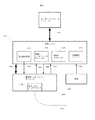
図1は、心エコーシステム及びカテーテルのハイレベルブロック図を示す。前記システムは、撮像エンジン3100と、患者用インタフェースモジュール(PIM)2000とを含む。撮像エンジン3100は、前記システムの中心的な構成要素であり、すべての画像生成、表示及びシステム構成要素の制御を実行する。撮像エンジン3100は、汎用処理ユニット3110、デジタル信号処理(DSP)モジュール3120及びPIMインタフェースモジュール3130から成る。PIM2000は、心エコーカテーテル1000と機械的及び電気的に接続されている。
FIG. 1 shows a high level block diagram of an echocardiographic system and catheter. The system includes an
カテーテルは、近位端及び遠位端を有する柔軟な管状体から成る一般的な医療器具である。本発明の実施例に従って構成されたカテーテルは、近位端を有する外方チューブと、該外方チューブ内に滑動可能に受け入れられ、前記外方チューブから遠位へ延在する内方シースと、前記外方チューブの前記近位端から前記内方シースに該内方シース内を伸長する回転軸(又は駆動ケーブル)とを含むことができる。前記回転軸は、前記外方チューブに関して軸方向に固定されており、前記内方シースに関して該内方シース内を軸方向に可動である。入れ子式部分を含むそのようなカテーテルの近位部の実施例は、例えば、米国特許出願番号第12/336,441明細書に詳細に開示されており、参照によってその全体が本明細書に含まれる。 A catheter is a common medical device consisting of a flexible tubular body having a proximal end and a distal end . A catheter constructed in accordance with an embodiment of the present invention includes an outer tube having a proximal end , an inner sheath slidably received within the outer tube and extending distally from the outer tube; A rotation axis (or drive cable) extending from the proximal end of the outer tube to the inner sheath can be included in the inner sheath. The rotating shaft is fixed in the axial direction with respect to the outer tube, and is movable in the axial direction within the inner sheath with respect to the inner sheath. Examples of the proximal portion of such a catheter including a telescoping portion are disclosed in detail, for example, in US patent application Ser. No. 12 / 336,441, which is hereby incorporated by reference in its entirety. It is.
図2は、超音波撮像コア11が配置される撮像ルーメン5を有する遠位シャフト3から成るカテーテルの遠位部を示す。前記遠位部は、一般的にポリエチレン又はナイロンなどの熱可塑性物質の押し出し成形によって形成される。前記遠位シャフトは、また熱可塑性物質の多層で形成することができる。前記遠位部は、さらに、隔壁15と、組織を傷つけない遠位先端17と、隔壁穿刺ポート19とを含む。隔壁15は、室温硬化型(RTV)シリコーンなどのポリマー材料で作ることができる。超音波を透過する無菌食塩水などの流体で遠位シースルーメン5を満たすために、注射針(図示せず)が、隔壁穿刺ポート19を通って挿入され、隔壁15を突き刺す。前記注射針が引き抜かれると、隔壁15は自己封止する。自己封止の隔壁の使用は、超音波撮像コア11が前記近位端に向けて並進するとき、前記遠位シース内への血液や空気などの流体の引き込みを防止する。
FIG. 2 shows the distal part of a catheter consisting of a
超音波撮像コア11は、遠位ハウジング組立体101に取り付けられた駆動ケーブル91を含む。遠位ハウジング組立体101は、遠位ハウジング111、トランスデューサ121及び伝送線131を含む。そのような遠位ハウジング111は、またトランスデューサスタック121の面を横切る流体の流れを促進する遠位開口113を含む。前記遠位ハウジングは、米国特許出願第12/330,308明細書に詳細に開示されており、ここに参照によってその全体が本明細書に含まれる。
The
遠位シャフト3は、少なくとも1つの層を有する細長い管から成る。前記遠位シャフトは、先細りにするか、又は直線状とすることができる。例えば、前記遠位シャフトは、心内経食道のカテーテルのために、0.080インチから0.350インチ(約2.03mm〜約8.89mm)の範囲の外径を有する直管とすることができる。前記外径は、心臓カテーテルのためには、より一般的に10Fr(0.131インチ)あるいはそれより小さいかもしれない。外径が8Fr(0.105インチ)以下の心臓カテーテルは、右心房からよりもAFアブレーション誘導に結像性能が良い場合がある左心房への経中隔ルート経由で送る方がよい。前記外径は、より一般的には、経鼻で送ることができる経食道カテーテルのために12Fr(0.158インチ)と、25Fr(0.328インチ)との間にあるかもしれない。
The
駆動ケーブル91は、一般的に少なくとも1つの単一又は多数の糸状ステンレス鋼又は同様な材料で、外形が一般的に0.10mmから3.50mmの範囲の丸、四角あるいは平らなワイヤを含む。正確な位置決めを確実にするために、加速中の駆動ケーブル91の伸び縮みは、最小化されなければならない。駆動ケーブル91は、また超音波撮像コア11の不均一な回転を最小化するべきである。
The
トランスデューサスタック121は、5MHzから60MHz、心内経食道撮像のためには一般的に5MHzから20MHzの間の周波数範囲で動作する。トランスデューサスタック121は、少なくとも圧電層を含む。トランスデューサスタック121は、さらに、一般的に、伝導層、少なくとも1つのマッチング層及びバッキング層を含む。撮像カテーテルのためのトランスデューサスタックは、当業者によく知られている。8Fr(フレンチ)の寸法のカテーテルのための典型的なトランスデューサは、約1.6mm×2.4mmの開口を有し、1cmと4cmとの間、一般的には2cmと3cmとの間に焦点距離を有する。トランスデューサの合焦方法は、トランスデューサ製造の当業者によく知られている。伝送線131は、前記患者用インタフェースモジュールに収納されたトランシーバ電子機器に、トランスデューサスタック121を電気的に接続する。
The
次に図3から6を参照するに、経食道心エコーカテーテルの遠位部のいくつかの実施例が図示されている。図3は、バルーンエンベロープ70、膨張ルーメン60、膨張ポート62及び超音波撮像コア10を含むカテーテルの遠位部の実施例の側面図を示す。超音波撮像コア10は駆動ケーブル90及び遠位ハウジング組立体100を含み、該遠位ハウジング組立体は、また、遠位ハウジング110、トランスデューサスタック120及び伝送線130を含む。遠位ハウジング110は、また、前記トランスデューサスタックの面を横切る流体の流れを促進する遠位開口112を含む。トランスデューサスタック120は、焦点を合わせ、あるいは焦点が合っていないようにすることができる。15Fr(フレンチ)の寸法のカテーテルのための典型的なトランスデューサは、最大約4.2mmの円形のアパーチャーを有し、1cmと4cmとの間、一般的には2cmと3cmとの間に焦点距離を有する。トランスデューサの合焦方法は、トランスデューサ製造の当業者によく知られている。
Referring now to FIGS. 3-6 , several examples of the distal portion of a transesophageal echocardiography catheter are illustrated. FIG. 3 shows a side view of an embodiment of the distal portion of the catheter that includes the
前記バルーン撮像カテーテルの前記遠位部は、また、シース2、遠位シースルーメン4、隔壁15、組織を傷つけない遠位先端16及び隔壁穿刺ポート18を含む。隔壁15は、室温硬化型(RTV)シリコーンなどのポリマー材料で作ることができる。使用に際し、超音波を透過する無菌食塩水などの流体で遠位シースルーメン4を満たすために、注射針(図示せず)が、隔壁穿刺ポート18を通って挿入され、隔壁15を突き刺す。前記注射針が引き抜かれると、隔壁15は自己封止する。自己封止の隔壁の使用は、超音波撮像コア10が前記近位端に向けて並進するとき、前記遠位シース内への空気などの流体の引き込みを防止する。
The distal portion of the balloon imaging catheter also includes a
前記バルーンカテーテルは、一般的に15Frであるか、それより小さく、経鼻ルートで食道へアクセスされるように十分に小さい。バルーンエンベロープ70は、ポリエチレン/EVAなどの柔軟なポリマーブレンドで形成することができ、前記遠位カテーテルシースの、前記膨張ポートの近位及び遠位の部分に、一般的に、接合又は溶融によって取り付けられている。前記バルーン組合せ体は、長さが2cmから10cmとすることができ、一般的に6cmである。バルーンエンベロープ70は、超音波を透過する無菌食塩水など流体を使って膨らませることができる。前記バルーンは、最大4cm、一般的には2cmと3cmとの間の直径に膨らませることができる。膨らんだ前記バルーンは、食道壁及び心臓構造の撮像を容易にする。
The balloon catheter is typically 15 Fr or smaller and small enough to allow access to the esophagus by the nasal route. The
次に図4を参照するに、経食道心エコー検査カテーテルの遠位部の代替実施例の側面図が示されている。前記遠位部は、バルーンエンベロープ70、膨張ルーメン60、膨張ポート62、収縮ルーメン61、収縮ポート63及び超音波撮像コア10を含む。超音波撮像コア10は駆動ケーブル90及び遠位ハウジング組立体100を含み、該遠位ハウジング組立体はさらに、遠位ハウジング110、トランスデューサスタック120及び伝送線130を含む。遠位ハウジング110は、また前記トランスデューサスタックの面を横切る流体の流れを促進する遠位開口112を含む。トランスデューサスタック120は、焦点を合わせ、あるいは焦点が合っていないようにすることができる。15Fr(フレンチ)の寸法のカテーテルのための典型的なトランスデューサは、最大約4.2mmの円形のアパーチャーを有し、1cmと4cmとの間、一般的には2cmと3cmとの間に焦点距離を有する。トランスデューサの合焦方法は、トランスデューサ製造の当業者によく知られている。
Turning now to FIG. 4, a side view of an alternative embodiment of the distal portion of a transesophageal echocardiography catheter is shown. The distal portion includes a
前記バルーン撮像カテーテルの前記遠位部はさらに、シース2、遠位シースルーメン4、隔壁15、組織を傷つけない遠位先端16及び隔壁穿刺ポート18を含む。隔壁15は、室温硬化型(RTV)シリコーンなどのポリマー材料で作ることができる。超音波を透過する無菌食塩水などの流体で遠位シースルーメン4を満たすために、注射針(図示せず)が、隔壁穿刺ポート18を通って挿入され、隔壁15を突き刺す。前記注射針が引き抜かれると、隔壁15は自己封止する。自己回復作用の隔壁の使用は、超音波撮像コア10が前記近位端に向けて並進するとき、前記遠位シース内への空気などの流体の引き込みを防止する。
The distal portion of the balloon imaging catheter further includes a
前記バルーンカテーテルは、一般的に15Frであるか、それより小さく、経鼻ルートで食道へアクセスされるように十分に小さい。バルーンエンベロープ70は、ポリエチレン/EVAなどの柔軟なポリマーブレンドで形成されており、前記遠位カテーテルシースの、前記膨張ポート62の近位及び遠位の部分に、一般的に、接合又は溶融によって取り付けられている。前記バルーン組合せ体は、長さが2cmから10cmとすることができ、一般的に6cmである。バルーンエンベロープ70は、超音波を透過する無菌食塩水など流体を使って膨らませることができる。前記バルーンは、最大4cm、一般的には2cmと3cmとの間の直径に膨らませることができる。膨らんだ前記バルーンは、食道壁及び心臓構造の撮像を容易にする。敏活な膨張/収縮の繰り返しは、無菌食塩水の循環を可能にする。循環する前記塩水は、潜在的に、食道壁で熱を取り除き、心房食道瘻の形成を防止するのに使用することができる。
The balloon catheter is typically 15 Fr or smaller and small enough to allow access to the esophagus by the nasal route.
次に図5を参照するに、経食道心エコー検査カテーテルの遠位部の他の実施例の側面図が示されている。前記遠位部は、バルーンエンベロープ70、膨張ルーメン60、膨張ポート62及び超音波撮像コア10を含む。超音波撮像コア10は駆動ケーブル90及び遠位ハウジング組立体100を含み、該遠位ハウジング組立体は、また遠位ハウジング110、トランスデューサスタック120及び伝送線130を含む。遠位ハウジング110は、また前記トランスデューサスタックの面を横切る流体の流れを促進する遠位開口112を含む。トランスデューサスタック120は、焦点を合わせ、あるいは焦点が合っていないようにすることができる。15Fr(フレンチ)の寸法のカテーテルのための典型的なトランスデューサは、最大約4.2mmの円形のアパーチャーを有し、1cmと4cmとの間、一般的には2cmと3cmとの間に焦点距離を有する。トランスデューサの合焦方法は、トランスデューサ製造の当業者によく知られている。
Referring now to FIG. 5, a side view of another embodiment of the distal portion of a transesophageal echocardiography catheter is shown. The distal portion includes a
前記バルーン撮像カテーテルの前記遠位部はさらに、シース2、遠位シースルーメン4、隔壁15、組織を傷つけない遠位先端16及び隔壁穿刺ポート18を含む。隔壁15は、室温硬化型(RTV)シリコーンなどのポリマー材料で作ることができる。超音波を透過する無菌食塩水などの流体で遠位シースルーメン4を満たすために、注射針(図示せず)が、隔壁穿刺ポート18を通って挿入され、隔壁15を突き刺す。前記注射針が引き抜かれると、隔壁15は自己封止する。自己封止の隔壁の使用は、超音波撮像コア10が前記近位端に向けて並進するとき、前記遠位シース内への空気などの流体の引き込みを防止する。
The distal portion of the balloon imaging catheter further includes a
前記バルーンカテーテルは、一般的に15Frであるか、それより小さく、経鼻ルートで食道へアクセスされるように十分に小さい。バルーンエンベロープ70は、ポリエチレン/EVAなどの柔軟なポリマーブレンドで形成することができ、前記遠位カテーテルシースの、前記膨張ポートの近位及び遠位の部分に、一般的に、接合又は溶融によって取り付けられている。前記バルーン組合せ体は、長さが2cmから10cmとすることができ、一般的に6cmである。バルーンエンベロープ70は、超音波を透過する無菌食塩水など流体を使って膨らませることができる。前記バルーンは、最大4cm、一般的には2cmと3cmとの間の直径に膨らませることができる。膨らんだ前記バルーンは、食道壁及び心臓構造の撮像を容易にする。遠位シースルーメン4と前記バルーンエンベロープの内面との間の流体交換ポート64、66、68は、超音波撮像コア10の進行及び後退に伴い、超音波を透過する流体の交換を可能にする。前記流体交換ポートは、超音波撮像コア10が遠位シース2の範囲内で後退するとき、負圧ポテンシャルの発生を有効に防止する液溜めを提供する。
The balloon catheter is typically 15 Fr or smaller and small enough to allow access to the esophagus by the nasal route. The
次に図6を参照するに、経食道心エコー検査カテーテルの遠位部のさらに他の実施例の側面図が示されている。前記遠位部は、バルーンエンベロープ72、膨張ルーメン60、膨張ポート62及び超音波撮像コア10を含む。超音波撮像コア10は駆動ケーブル90及び遠位ハウジング組立体100を含み、該遠位ハウジング組立体はさらに、遠位ハウジング110、トランスデューサスタック120及び伝送線130を含む。遠位ハウジング110はさらに、前記トランスデューサスタックの面を横切る流体の流れを促進する遠位開口112を含む。トランスデューサスタック120に焦点を合わせることも、あるいは焦点を合わせないこともできる。15Fr(フレンチ)の寸法のカテーテルのための典型的なトランスデューサは、最大約4.2mmの円形のアパーチャーを有し、1cmと4cmとの間、一般的には2cmと3cmとの間に焦点距離を有する。トランスデューサの合焦方法は、トランスデューサ製造の当業者によく知られている。
Referring now to FIG. 6, a side view of yet another embodiment of the distal portion of a transesophageal echocardiography catheter is shown. The distal portion includes a
前記バルーン撮像カテーテルの前記遠位部はさらに、シース2、遠位シースルーメン4、隔壁15、組織を傷つけない遠位先端16及び隔壁穿刺ポート18を含む。隔壁15は、室温硬化型(RTV)シリコーンなどのポリマー材料で作ることができる。超音波を透過する無菌食塩水などの流体で遠位シースルーメン4を満たすために、注射針(図示せず)が、隔壁穿刺ポート18を通って挿入され、隔壁15を突き刺す。前記注射針が引き抜かれると、隔壁15は自己封止する。自己封止の隔壁の使用は、超音波撮像コア10が前記近位端に向けて並進するとき、前記遠位シース内への空気などの流体の引き込みを防止する。
The distal portion of the balloon imaging catheter further includes a
遠位シース2は、超音波ゲル伝達媒質などの超音波伝達媒質を使用して食道壁につながれる(coupled)。前記カテーテルは、食道壁に関する適所位置に前記バルーンの膨張によって保持される。前記バルーンは、一般的に、前記カテーテルの心臓から遠位側に拡大する。前記バルーンカテーテルは、一般的に15Frであるか、それより小さく、経鼻ルートで食道へアクセスされるように十分に小さい。バルーンエンベロープ72は、ポリエチレン/EVAなどの柔軟なポリマーブレンドで形成することができ、前記遠位カテーテルシースの、前記膨張ポート62の近位及び遠位の部分に、一般的に、接合又は溶融によって取り付けられている。前記バルーン組合せ体は、長さが2cmから10cmとすることができ、一般的に6cmである。バルーンエンベロープ72は、放射線不透過性の造影剤、無菌食塩水又はその混合物などの流体を使って膨らませることができる。膨らんだ前記バルーンは前記撮像コア及び食道壁より後にあるので、前記流体は超音波を透過する必要はない。膨らんだ前記バルーンは食道壁と心臓の構造との撮像を容易にする。
The
次に図7から9を参照するに、前記患者用インタフェースモジュールのいくつかの実施例が示されている。前記患者用インタフェースモジュールは、前記カテーテル及び前記撮像エンジン間の電気−機械インタフェースである。前記患者用インタフェースモジュールは、超音波発生器、受け入れ器及びスキャンニング機構を含む。図7は、患者用インタフェースモジュール2000の一実施例の側面図を示す。患者用インタフェースモジュール2000は、前記撮像カテーテルの超音波撮像コア(図示せず)と機械的及び電気的に接続されている。患者用インタフェースモジュール2000は、前記超音波撮像コアの直線並進及び回転のための手段を含む。前記カテーテルの入れ子式部分の前記近位端は、アンカーマウント2032に取り付けられる。回転装置2602は、機械的及び電気的に前記カテーテル撮像コアの前記近位端に結合し、該カテーテル撮像コアの回転及び直線並進の双方を可能にする。
7-9, several embodiments of the patient interface module are shown. The patient interface module is an electro-mechanical interface between the catheter and the imaging engine. The patient interface module includes an ultrasound generator, a receiver and a scanning mechanism. FIG. 7 shows a side view of one embodiment of a
患者用インタフェースモジュール2000は、さらに、電力回路基板2100、トランシーバ(XCVR)回路基板2200、動作制御(M/C)モジュール2300及び直線位置感知アレイ2420を含む。電力回路基板2100は、トランシーバ回路基板2200、動作制御モジュール2300及び直線位置感知アレイ2420と、電気的に接続されている(図示せず)。
The
動作制御モジュール2300は、直線圧電モータ2402、直線位置感知アレイ2420、回転モータ2502及び回転エンコーダリーダ2516と電気接続(2302、2304、2306、2308)された電子機器を含む。動作制御モジュール2300は、さらに、前記撮像エンジン(図示せず)と電気接続(2310、3050)されており、位置情報を提供する。動作制御モジュール2300は、さらに、前記患者用インタフェースモジュールの外面に配置される一組の患者用インタフェースモジュール運転制御ボタン(図示せず)と電気接続することができる。
The
前記直線圧電モータは、モータハウジング2402、ロッド2406及び板ばね2408、2410を含む。圧電モータの利点は、低質量、急な加速及び減速、双方向の並進(又は循環運動)及び高速度(最高450mm/秒)にある。圧電モータハウジング2402、並進ステージ2490、回転モータ2502及び取付けブロック2510は剛的に固定される。圧電モータハウジング2402と並進ステージ2490などの剛的に固定された構成要素とは、ロッド2406に沿って動く。
The linear piezoelectric motor includes a
回転モータ2502は、第1及び第2の歯車2506、2508に機械的に結合される。代替的に、回転モータ2502は、第1及び第2のプーリに機械的に結合することができる。回転モータ2502は、前記超音波撮像コアの連続回転を可能にする。回転モータは、少なくとも8000回/分(RPM)まで動作する。第2の歯車2508は、駆動軸2604に固定的に取付けられている。前記駆動軸は、また回転装置2602を含む。
The
駆動軸2604は取付けブロック2510内に収納されている。前記取付けブロックは、アルミニウム又はチタンなどの軽量材料で機械加工するか、鋳造することができ、さらに電気的遮蔽を提供することができる。また、エンコーダホイール2514は、駆動軸2604に固定的に取り付けられており、その結果、エンコーダリーダ2516がエンコーダホイール2514の位置を読むことができる。エンコーダホイール2514及びエンコーダリーダ2516は、駆動軸2604の回転位置の追跡を可能にする。
The
前記直線位置感知装置は、異方性磁気抵抗(AMR)センサー2422〜2450のアレイ2420と、永久磁石2404とを含む。永久磁石2404は、圧電モータハウジング2402に固定的に取り付けられている。アレイ2420は、正確かつ精密な永久磁石2404の位置感知を可能にする。前記カテーテル撮像コアが圧電モータハウジング2402及び永久磁石2404に機械的に結合されるので、前記カテーテル撮像コアの遠位ハウジング及びトランスデューサスタックの相対的な軸方向位置を決めることができる。前記AMRセンサーは、磁石の移動範囲に沿って周期的にかつ該磁石からずれて置かれている。前記AMRセンサーの間隔は8mmにまですることができる。前記AMRセンサーは、位置感知の移動範囲を拡張するために追加することができる。前記センサーの前記永久磁石との離隔距離は、該永久磁石の磁極面での電界の強さに依存する。前記離隔距離は、セラミック及びアルニコの磁石については最高0.25インチ(約6ミリメートル)まで、またネオジムタイプなどの希土類磁石については最高0.5インチ(約13ミリメートル)とすることができる。位置解像度は、8mmのAMRセンサー間隔では1%よりも良好な精度で約0.002インチ(50μm)である。解像度及び精度は、センサー間隔を小さくすることによって改善することができる。
The linear position sensing device includes an
トランシーバ回路基板2200は、超音波信号の送受信のためのアナログ電子機器を含む。トランシーバ回路基板2200は、前記撮像エンジン(図示せず)と電気接続(2022、3050)されている。さらに、トランシーバ回路基板2200は、液体金属ロータリカプラー2610及び駆動軸2604と電気接続2202されている。駆動軸2604の電気部品は、電気ジャック2608、変圧器2606及び回転装置2602内の電気接触子組立体(図示せず)を含む。前記電気接触子組立体は、前記カテーテル撮像コアの前記伝送線と電気接続されている。
次に図8を参照するに、患者用インタフェースモジュール2000の他の実施例の側面図が示されている。患者用インタフェースモジュール2000は、前記撮像カテーテルの超音波撮像コア(図示せず)と機械的及び電気的に接続されている。患者用インタフェースモジュール2000は、前記超音波撮像コアの直線並進及び回転のための手段を含む。前記カテーテルの入れ子式部分の前記近位端は、アンカーマウント2032に取り付けられている。回転装置2602は、前記カテーテル撮像コアの前記近位端に機械的に結合され、前記カテーテル撮像コアの回転及び直線並進の双方を可能にする。
Referring now to FIG. 8, a side view of another embodiment of a
患者用インタフェースモジュール2000は、さらに、電力回路基板2100、トランシーバ(XCVR)回路基板2200及び動作制御(M/C)モジュール2300を含む。電力回路基板2100、トランシーバ回路基板2200及び動作制御モジュール2300と電気接続(図示せず)されている。
The
動作制御モジュール2300は、直線圧電モータ及びエンコーダ装置2460、回転モータ2502及び回転エンコーダリーダ2516と電気接続2305、2306、2308する電子機器を含む。動作制御モジュール2300は、さらに、前記撮像エンジン(図示せず)と電気接続2310、3050されており、位置情報を提供する。動作制御モジュール2300は、さらに、前記患者用インタフェースモジュールの外面に置かれる一組の患者用インタフェースモジュール操作制御ボタン(図示せず)と電気接続され得る。
The
前記直線圧電モータは、モータハウジング2460、ロッド2406及び板ばね2408、2410を含む。圧電モータの利点は、低質量、急な加速及び減速、双方向の並進(又は循環運動)及び高速度(最高450mm/秒)にある。直線圧電モータ及びエンコーダ装置のハウジング2460、並進ステージ2490、回転モータ2502及び取付けブロック2510は剛的に固定される。直線圧電モータ及びエンコーダ装置のハウジング2460と、並進ステージ2490などの剛的に固定された構成要素とは、ロッド2406に沿って動く。回転モータ2502は、第1及び第2の歯車2506、2508に機械的に結合される。代替的に、回転モータ2502は、第1及び第2のプーリに機械的に結合することができる。
The linear piezoelectric motor includes a
回転モータ2502は前記超音波撮像コアの連続回転を可能にする。回転モータは、少なくとも最高8000回/分(RPM)で動作する。第2の歯車2508は駆動軸2604に固定的に取り付けられている。前記駆動軸は、さらに回転装置2602を含む。前記直線エンコーダ装置は、駆動軸2604の軸線方向位置の追跡を可能にする。
A
駆動軸2604は,取付けブロック2510内に収納されている。前記取付けブロックは、アルミニウム又はチタンなどの軽量材料で機械加工されるか、鋳造することができ、さらに電気的遮蔽を提供することができる。また、エンコーダホイール2514は、駆動軸2604に固定的に取り付けられており、その結果、エンコーダリーダ2516がエンコーダホイール2514の位置を読むことができる。エンコーダホイール2514及びエンコーダリーダ2516は、駆動軸2604の回転位置の追跡を可能にする。
The
トランシーバ回路基板2200は、超音波信号の送受信のためのアナログ電子機器を含む。トランシーバ回路基板2200は、前記撮像エンジン(図示せず)と電気接続(2022、3050)されている。さらに、トランシーバ回路基板2200は、液体金属ロータリカプラー2610及び駆動軸2604と電気接続2202されている。駆動軸2604の電気部品は、電気ジャック2608、変圧器2606及び回転装置2602内の電気接触子組立体(図示せず)を含む。前記電気接触子組立体は、前記カテーテル撮像コアの前記伝送線と電気接続されている。
次に図9を参照するに、患者用インタフェースモジュール2000のさらに他の実施例の側面図が示されている。患者用インタフェースモジュール2000は、前記撮像カテーテルの超音波撮像コア(図示せず)と機械的及び電気的に接続されている。患者用インタフェースモジュール2000は、前記超音波撮像コアの直線並進及び回転のための手段を含む。前記カテーテルの入れ子式部分の前記近位端は、アンカーマウント2032に取り付けられている。駆動軸2603及び回転装置260は、前記カテーテル撮像コアの前記近位端に機械的及び電気的に結合され、前記カテーテル撮像コアの回転及び直線並進の双方を可能にする。
Referring now to FIG. 9, a side view of yet another embodiment of the
患者用インタフェースモジュール2000は、さらに、電力回路基板2100、トランシーバ(XCVR)回路基板2200及び動作制御(M/C)モジュール2300を含む。電力回路基板2100、トランシーバ回路基板2200及び動作制御モジュール2300と電気接続(図示せず)されている。
The
動作制御モジュール2300は、回転モータ2502及び回転エンコーダリーダ2516と電気接続2306、2308する電子機器を含む。動作制御モジュール2300は、さらに、前記撮像エンジン(図示せず)と電気接続2310、3050されており、位置情報を提供する。動作制御モジュール2300は、さらに、前記患者用インタフェースモジュールの外面に置かれる一組の患者用インタフェースモジュール操作制御ボタン(図示せず)と電気接続され得る。低摩擦並進ステージ2478及びカテーテル撮像コアの相対的な直線位置は、回転位置から決定される。代替的に図3で示すように直線位置感知装置などの直線位置センサーは、前記カテーテル撮像コアの長手方向位置の曖昧さを低減するために含ませ得る。
The
回転モータ2502は、第1のピニオン歯車2505に機械的に結合されている。前記第1のピニオン歯車は、第1の歯車2476に噛合する。第1の歯車2476は第2のピニオン歯車2507に噛合する。第1の歯車2476は、またリンクアーム2472の第1の端部2473に固定的に取り付けられている。リンクアーム2472の第2の端部2471は、リンクアームマウント2470に固定的に取り付けられている。第1の歯車2476及び回転モータ2502は、低摩擦並進ステージ2478に固定的に取り付けられている。第2のピニオン歯車2507は、第2の歯車2509に固定的に取り付けられている。第2の歯車2509は、駆動軸2603に固定的に取り付けられた第3の歯車2511に噛合する。代替的に、第2及び第3の歯車2507、2509に代えて第1及び第2のプーリを使うことができる。
The
回転モータ2502は、超音波撮像コアの連続回転及び並進を可能にする。第1のピニオン歯車2505が回転するに伴い、リンクアーム2472の第1の歯車2476及び第1の端部2473は、第1の歯車2476の回転軸のまわりで回転する。リンクアーム2472の周期的な運動は、低摩擦並進ステージ2478を前後に滑らせる。低摩擦並進ステージ2478の前記前後の運動は、前記撮像コアを対応して前後に並進させる、すなわち長手方向へ反復させる。直線並進の範囲は、リンクアーム2472の第1の端部2473から第1の歯車2476の回転軸までの距離で決まる。歯車及びリンクアーム系の利点は、直線並進モータから成っている実施例に比較して、ある程度、より簡素な構造、低重量及び低コストにある。
The
駆動軸2603は取付けブロック2511内に収納されている。前記取付けブロックは、アルミニウム又はチタンなどの軽量材料で機械加工するか、鋳造することができ、さらに電気的遮蔽を提供することができる。また、エンコーダホイール2514は、駆動軸2603に固定的に取り付けられており、その結果、エンコーダリーダ2516がエンコーダホイール2514の位置を読むことができる。エンコーダホイール2514及びエンコーダリーダ2516は、駆動軸2604の回転位置の追跡を可能にする。
The drive shaft 2603 is housed in the mounting block 2511. The mounting block can be machined or cast from a lightweight material such as aluminum or titanium and can further provide electrical shielding. Further, the encoder wheel 2514 is fixedly attached to the drive shaft 2603, so that the encoder reader 2516 can read the position of the encoder wheel 2514. Encoder wheel 2514 and encoder reader 2516 allow tracking of the rotational position of
トランシーバ回路基板2200は、超音波信号の送受信のためのアナログ電子機器を含む。トランシーバ回路基板2200は、前記撮像エンジン(図示せず)と電気接続(2022、3050)されている。さらに、トランシーバ回路基板2200は、液体金属ロータリカプラー2610及び駆動軸2603と電気接続2202されている。駆動軸2604の電気部品は、電気ジャック2608、変圧器2606及び回転装置2602内の電気接触子組立体(図示せず)を含む。前記電気接触子組立体は、前記カテーテル撮像コアの前記伝送線と電気接続されている。
前記超音波撮像コアの高速直線並進及び回転と正確な位置感知との組合せは、心臓構造などの動く構造体の容積測定のスキャンを可能にする。周期的な直線並進は、関心容積の連続するリアルタイム撮像を可能にする。代わりのトランスデューサ構造は、心臓のアブレーション手術の画像誘導のためにさらなる利点を提供することができる。 The combination of high-speed linear translation and rotation of the ultrasound imaging core and accurate position sensing allows for volumetric scanning of moving structures such as heart structures. Periodic linear translation allows continuous real-time imaging of the volume of interest. Alternative transducer structures can provide additional advantages for image guidance in cardiac ablation surgery.
次に図10を参照するに、多重トランスデューサ組立体を含む経食道心エコー検査カテーテルの遠位部の実施例が部分的に破断して示されている。前記遠位部は、バルーンエンベロープ70、膨張ルーメン60、膨張ポート62及び超音波撮像コア40を含む。超音波撮像コア40は駆動ケーブル490及び遠位ハウジング組立体400を含む。遠位ハウジング組立体400は、4つのトランスデューサハウジング412、414、416、418、4つのトランスデューサスタック422、424、426、428及び可撓性を有する3つのハウジング継ぎ手404、406、408を含む。前記4つのトランスデューサハウジングは、さらに、前記トランスデューサスタックの面を横切る流体の流れを促進する遠位開口442、444、446、448を含む。前記個々のトランスデューサ及びハウジングは、図2に示されたと実質的に類似の構造である。
Referring now to FIG. 10, an embodiment of the distal portion of a transesophageal echocardiography catheter that includes a multiple transducer assembly is shown partially cut away. The distal portion includes a
前記多重トランスデューサ組立体は、いくつかの技術に従って組み立てることができる。典型的な構造では、前記多重のトランスデューサハウジング及び継ぎ手は、単一のステンレス鋼ハイポチューブから組み立てることができる。前記トランスデューサハウジングは、適合したスロットによって個々の前記トランスデューサ組立体に剛的支持を提供する。前記継ぎ手は、前記ハイポチューブを渦巻状に切断した部分であり、前記多重トランスデューサ組立体のために軸方向の剛性と曲げの柔軟性とを釣り合わせる。渦巻状の切断ピッチは、一定に、あるいは目標とする剛性に応じて変化させることができる。前記ピッチは、柔軟性を下げるために増大するか、柔軟性を上げるために減少させることができる。ある柔軟性は、カテーテルの経鼻位置決めを容易にする。典型的な構造では、前記トランスデューサハウジングは長さ約4mmであり、前記トランスデューサ継ぎ手は長さ約6mmであり、前記トランスデューサの直径は2.5mmである。渦巻状に切断した前記継ぎ手のピッチは典型的には1mmであり、100ミクロンの切り口幅を有する。前記多重トランスデューサ組立体の代わりの実施例では、前記トランスデューサハウジング継ぎ手は、前記トランスデューサハウジングに取り付けられたステンレス鋼駆動ケーブルなどの別個の素材とすることができる。 The multiple transducer assembly can be assembled according to several techniques. In a typical construction, the multiple transducer housings and fittings can be assembled from a single stainless steel hypotube. The transducer housing provides rigid support to the individual transducer assemblies by matched slots. The joint is a spiral cut of the hypotube and balances axial stiffness and bending flexibility for the multiple transducer assembly. The spiral cutting pitch can be changed constantly or according to the target stiffness. The pitch can be increased to decrease flexibility or decreased to increase flexibility. Some flexibility facilitates nasal positioning of the catheter. In a typical construction, the transducer housing is about 4 mm long, the transducer joint is about 6 mm long, and the transducer diameter is 2.5 mm. The pitch of the joint cut in a spiral is typically 1 mm and has a cut width of 100 microns. In an alternative embodiment of the multiple transducer assembly, the transducer housing joint may be a separate material, such as a stainless steel drive cable attached to the transducer housing.
図10に示されているように、相互に最も近接するトランスデューサの方向は、互いに90°だけずれている。第1のトランスデューサスタック422は図面の頂部に向き、第2のトランスデューサスタック424は紙背方向へ向き、第3のトランスデューサスタック426は図面の底部に向き、第4のトランスデューサスタック428は図面から出る方向へ向く。前記複数のトランスデューサの回転オフセットは、トランスデューサ間での、組織からの散乱した超音波エネルギーの潜在的な相互干渉を最小化する。多重トランスデューサ組立体の利点は、増大した3D画像撮像フレームレートにある。前記トランスデューサ組立体の周期的な直線並進移動範囲は、前記トランスデューサの数と、トランスデューサ離隔距離とに応じて減少することができる。完全な3D画像は、個々のトランスデューサからのより小さな3D画像から形成することができる。図10に示された典型的な構造で4cmの高さの画像容積のために、約1cmの移動経路が必要とされる。これは、1つの要素トランスデューサ組立体のそれに比べての約4倍のフレームレートの増加をもたらす。
As shown in FIG. 10, the directions of the transducers closest to each other are offset from each other by 90 °. The
前記バルーン撮像カテーテルの前記遠位部はさらに、シース2、遠位シースルーメン4、隔壁15、組織を傷つけない遠位先端16及び隔壁穿刺ポート18を含む。隔壁15は、室温硬化型(RTV)シリコーンなどのポリマー材料で作られる。超音波を透過する無菌食塩水などの流体で遠位シースルーメン4を満たすために、注射針(図示せず)が、隔壁穿刺ポート18を通って挿入され、隔壁15を突き刺す。前記注射針が引き抜かれると、隔壁15は自己封止する。自己封止の隔壁の使用は、超音波撮像コア10が前記近位端に向けて並進するとき、前記遠位シース内への空気などの流体の引き込みを防止する。
The distal portion of the balloon imaging catheter further includes a
前記バルーンカテーテルは、一般的に15Frであるか、それより小さく、経鼻ルートで食道へアクセスされるように十分に小さい。バルーンエンベロープ70は、ポリエチレン/EVAなどの柔軟なポリマーブレンドで形成され、前記遠位カテーテルシースの、前記膨張ポート62の近位及び遠位の部分に、一般的に、接合又は溶融によって取り付けられている。前記バルーン組合せ体は、長さが2cmから10cmであり、一般的に6cmである。バルーンエンベロープ70は、超音波を透過する無菌食塩水など流体を使って膨らませられる。前記バルーンは、最大4cm、一般的には2cmと3cmとの間の直径に膨らませることができる。膨らんだ前記バルーンは、食道壁及び心臓構造の撮像を容易にする。
The balloon catheter is typically 15 Fr or smaller and small enough to allow access to the esophagus by the nasal route. The
ここで図11を参照するに、これまでに記載された経食道心エコー検査カテーテル及びシステムによって左心房壁の感受性基質を識別する例示的な一組の処理段階が示される。ステップ3200で最初に画像データが取得される。次に、ステップ3202で、心臓壁は、例えば左心房室の血液、食道壁、脂肪体及びアブレーション機器を含む周辺の組織及び機器から分けられる。次に、分けられた画像データは、ステップ3204で、レンジに依存する振幅及び周波数変化を含むシステム及びトランスデューサ効果を補償される。次に、ステップ3206で、左心房壁に一致する分けられた画像データから組織分類子(tissue classifier)が計算される。組織分類子は画像データの分析によって計算することができ、時間領域解析と称されている。組織分類子は、また画像データのスペクトル特性の分析によって計算することができ、周波数領域分析と称されている。典型的な組織分類子は、超音波の組織分類技術の当業者に知られている積分後方散乱(integrated backscatter)と減衰傾斜(slope-of-attenuation)を含むことができる。当業者に知られている組織分類への一つのアプローチは、サンプルから成る容積測定の関心領域(ROI)を近隣の画像ベクトルから選ぶことである。サンプルの数とベクトルの数は、機器とアプリケーションとに依存する。例えば図10に示されたような多重トランスデューサ組立体から2cmの範囲で約1mm×1mm×1mmの容積の画像データからのROIは、0.7°の面内ベクトル間隔、100×106サンプル/秒のサンプリングレート及び2mmの厚みのスライスを仮定すると、5ベクトル×129サンプル×1スライスを必要とする。組織分類子は、次に、補償された画像データから計算される。左心房壁の感受性基質は、ステップ3208で、計算された組織分類子によって識別される。感受性基質は、増大した間質線維症の容積によって特徴付けられることが知られている。間質性線維症の主要成分はコラーゲンであり、コラーゲンはその超音波特性によって識別することができる。正常な左心房壁からの感受性基質を区別は、経験的に決定される。積分後方散乱、減衰傾斜及び音速などの典型的な超音波組織分類子は、コラーゲン含有量に相関する。洞律動の患者にとって、心臓の拍動サイクルでの組織分類子の変化は、また、感受性基質を識別するために使うことができる。
Referring now to FIG. 11, an exemplary set of processing steps for identifying left atrial wall sensitive substrates with the transesophageal echocardiography catheters and systems described thus far is shown . In
図12は、アブレーションの滴定、潜在的有害事象の表示、心臓のアブレーション手術の結果として生じる左心房壁の壊死組織の識別のための典型的な一組の処理段階を示す。ステップ3402のアブレーションに先立って、ステップ3400で左心房壁のベースライン画像データが取得される。組織は、RFアブレーション及び冷凍アブレーションを含む複数の技術によって除去することができる。アブレーション後の画像データは、ステップ3404で取得され、アブレーション箇所毎で評価される。アブレーション前後の画像データは、同じ組織ボリュームが分析されることを保証するために、共同で登録される。動きに対する補償は、共同登録の前に必要に応じて画像収集間にステップ3406で提供される。次に、ステップ3408で、左心房壁は、例えば左心房室の血液、食道壁、脂肪体及びアブレーション機器を含む周辺の組織及び機器から分けられる。次に、分けられた画像データは、ステップ3410で、レンジに依存する振幅及び周波数変化を含むシステム及びトランスデューサ効果を補償される。次に、ステップ3412で、左心房壁に一致する分けられた画像データから組織分類子(tissue classifier)が計算される。積分後方散乱、熱歪み及び減衰傾斜の計算が当業者に知られている。潜在的な有害事象は、計算された組織分類子によってステップ3414で示される。有害事象の表示は、微小な泡形成、食道壁などの組織の過熱及び血栓形成を含むことができる。例えば、無脂肪の組織の温度上昇は、エコー輝度の増大、より大きな熱歪み及び減衰傾斜の減少に相関する。潜在的な有害事象と一致する組織分類子のレンジは、経験的に決定される。また、左心房壁の壊死組織は、計算された組織分類子によって、ステップ3416で識別される。壊死組織は、エコー輝度の増大によって、ある程度、特徴付けられることが知られている。洞律動の患者にとって、心臓の拍動サイクルでの組織分類子の変化は、また、感受性基質を識別するために使うことができる。生存する左心房壁からの壊死組織の区別は経験的に決定される。
FIG. 12 shows an exemplary set of processing steps for ablation titration, indication of potential adverse events, and identification of left atrial wall necrotic tissue resulting from cardiac ablation surgery. Prior to the ablation in
複数のトランスデューサを含む超音波撮像コアの高速直線並進及び回転は、容積測定の撮像レートを増大させることができる。特定の画像処理アルゴリズムは、心臓アブレーション手術のための画像誘導を容易にする。複数のトランスデューサ及びアレイのさらに他の構成は、合成開口が複数の物理的(すなわち現実の)開口の組み合わせから成るリアルタイムの合成開口撮像を可能にする。合成開口撮像は、画質を高めることを可能にする。周期的な直線並進は、関心容積の連続するリアルタイムの3D合成開口撮像を可能にする。 High speed linear translation and rotation of an ultrasound imaging core that includes multiple transducers can increase the volumetric imaging rate. Certain image processing algorithms facilitate image guidance for cardiac ablation surgery. Still other configurations of multiple transducers and arrays allow real-time synthetic aperture imaging where the synthetic aperture consists of a combination of multiple physical (ie, real) apertures. Synthetic aperture imaging makes it possible to improve image quality. Periodic linear translation enables continuous real-time 3D synthetic aperture imaging of the volume of interest.
次に図13を参照するに、2個式トランスデューサ組立体の撮像コア20の実施例の側面図が示されている。撮像コア20は、駆動ケーブル290及び遠位ハウジング組立体200を含む。遠位ハウジング組立体200は、トランスデューサハウジング210、第1のトランスデューサスタック222及び第2のトランスデューサスタック224を含む。トランスデューサハウジング210は、さらに、第2のトランスデューサスタック224の面を横切る流体の流れを促進する遠位開口212を含む。典型的なレイアウトでは、トランスデューサハウジング210は、第1及び第2のトランスデューサスタック222、224が反対方向に向いて配置される、レーザカットのステンレス鋼ハイポチューブを含む。端と端との素子間隔は、トランスデューサ幅、直線並進速度、回転速度及び送信シーケンスに依存する合成開口撮像要件を満たすように、設計される。
Referring now to FIG. 13, a side view of an embodiment of the
次に図14Aから14Dを参照するに、図13に示された前記2個式トランスデューサ撮像コアのための送信及び運動シーケンスの一実施例が示されている。第1及び第2のトランスデューサスタック222、224は、開口寸法及び撮像周波数を含めてほぼ同じ物理特性を有する。合成開口220は、前記送信及び運動シーケンスが前記撮像コアの回転毎にトランスデューサ開口幅を追加するように、形成される。前記撮像コアの完全な360°の回転は時間ΔTで生じる。前記素子間の間隔はトランスデューサ開口幅の半値である。図14Aに見られるように、第2のトランスデューサスタック224が最初に起動(fired)される(224−1)。前記撮像コアは、180°(πラジアン)回転した後、図14Bに見られるようにトランスデューサ開口幅の半値だけ遠位側へ並進する。次に、第1のトランスデューサスタック222が起動し始める(222−1)。前記撮像コアは、さらに180°回転し、図14Cに示されている位置へトランスデューサ開口幅の半値だけ遠位側へ並進する。完全な一回転で、前記撮像コアはトランスデューサ幅を並進する。図14Dに見られるように、前記遠位側のトランスデューサは、次に第2の起動シーケンスを開始する(224−2)。前記撮像コアのそれぞれのさらなる回転は、トランスデューサ幅だけ合成開口の幅を増大させ、サブ開口の重複のための信号平均を可能にする。開口の広がりに伴い、合成開口の有効方位分解能は改善する。前記トランスデューサ幅、素子間隔、直線並進速度、回転速度及び送信シーケンスは、合成開口寸法、合成開口の要素数及びサブ開口重複範囲を修正するために、変更することができる。
Referring now to FIGS. 14A-14D, one embodiment of a transmission and motion sequence for the dual transducer imaging core shown in FIG. 13 is shown. The first and second transducer stacks 222, 224 have substantially the same physical characteristics including aperture dimensions and imaging frequency. A
AFアブレーションの画像誘導にとって、4cmの視野は心内経食道の撮像に適するであろう。血管内への超音波適用に使われる機械的に回転する撮像カテーテルに適するように、図13及び14の前記撮像コアの前記2個式トランスデューサ構成は、完全な360°のセクタというよりも180°のセクタにわたる撮像が適している。各送受信シーケンスのために約50μ秒を必要とする。180°セクタ(角度幅)及び256のベクトルから成る画像フレームは、その取得のために約13m秒を必要とする。1.6mm幅のトランスデューサ及び0.8mmの素子間隔を有する2つのトランスデューサ構成では、20mm/秒の並進速度及び1800RPMの回転速度は、1秒あたり60個の2Dフレームを実現する。それぞれのさらなる回転は、約25ミリ秒以内に2つの画像フレームを取得し、合成開口の幅を1.6mm分だけ拡張する。4cmの移動距離では、前記急速な周期的並進は、1秒あたり約2個の3D画像の連続的な3D画像フレームレートを可能にする。3D画像フレームレートは、画像範囲と移動距離とを低減することによって、増大することができる。 For AF ablation image guidance, a 4 cm field of view would be suitable for intracardiac transesophageal imaging. To be suitable for mechanically rotating imaging catheters used for intravascular ultrasound applications, the dual transducer configuration of the imaging core of FIGS. 13 and 14 is 180 ° rather than a full 360 ° sector. It is suitable for imaging over a number of sectors. Approximately 50 microseconds are required for each transmit / receive sequence. An image frame consisting of 180 ° sectors (angular width) and 256 vectors requires about 13 ms for its acquisition. In a two transducer configuration with a 1.6 mm wide transducer and 0.8 mm element spacing, a translation speed of 20 mm / sec and a rotational speed of 1800 RPM achieves 60 2D frames per second. Each further rotation acquires two image frames within about 25 milliseconds and extends the width of the synthetic aperture by 1.6 mm. At a 4 cm travel distance, the rapid periodic translation allows a continuous 3D image frame rate of about 2 3D images per second. The 3D image frame rate can be increased by reducing the image range and travel distance.
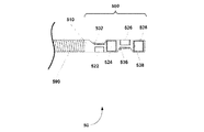
次に図15を参照するに、4個式トランスデューサ組立体を含む撮像コア50の実施例の側面図が示されている。撮像コア50は、駆動ケーブル590及び遠位ハウジング組立体500を含む。前記遠位ハウジング組立体は、トランスデューサハウジング510及び4個のトランスデューサスタック522、524、526、528を含む。前記4個のトランスデューサ組立体のレイアウトは、一般的に、90°セクタフレームを表示する撮像応用によく適している。前記トランスデューサ幅、素子間隔、直線並進速度、回転速度及び送信シーケンスは、合成開口寸法、合成開口の要素数及びサブ開口重複範囲を修正するために、変更することができる。5個分のトランスデューサ幅を合わせた幅を有しサブ開口の重複のない合成開口は、前記素子間隔がトランスデューサ幅の半値であるとき達成され、前記撮像コアは90°回転毎に前記素子間隔を並進し、また前記トランスデューサは、第1のトランスデューサスタック(最遠位)528から、第2のトランスデューサスタック526、第3のトランスデューサスタック524、その次に第4のトランスデューサスタック(最近位)522の順で起動(fire)する。
Referring now to FIG. 15, a side view of an embodiment of an
次に図16を参照するに、2列のトランスデューサアレイを含む撮像コア90の実施例の側面図が示されている。撮像コア90は、駆動ケーブル990及び遠位ハウジング組立体900を含む。遠位ハウジング組立体900は、トランスデューサハウジング910、第1の4要素のトランスデューサアレイ920及び第2の4要素のトランスデューサアレイ930を含む。第1のトランスデューサアレイ920は、切り口により実質的に機械的に分離された4個の独立な素子922、924、926、928を含む。トランスデューサアレイ930は、切り口により実質的に機械的に分離された4個の独立な素子932、934、936、938を含む。各トランスデューサ素子は、一般的に、はんだ付けするか、導電性接着剤によって、伝送線(図示せず)に取り付けられている。各トランスデューサアレイの前記トランスデューサ素子は独立して作動することができる。前記撮像エンジンに十分な数の信号チャンネルがあれば、第1及び第2のトランスデューサアレイ920、930をさらに独立して作動させることができる。前記撮像エンジンの信号チャンネルを共有する必要がある場合、第1及び第2のトランスデューサアレイ920、930を多重化することができる。
Referring now to FIG. 16, a side view of an embodiment of an
前記トランスデューサアレイは、背合わせに配置される。各トランスデューサは、別個の基材を有することができる。背合わせのトランスデューサは、共通基材を共有することもできる。2つのトランスデューサアレイ組立体900は、連続するリアルタイムの3D合成開口撮像のための図13に示された2個式トランスデューサ組立体200と同様に作動することができる。トランスデューサアレイの利点には、動的送信フォーカス(dynamic transmit focusing)も含まれる。
The transducer arrays are arranged back to back. Each transducer can have a separate substrate. Back-to-back transducers can also share a common substrate. The two
図17Aから17Cは、前記撮像コアの一回転で取得されるトランスデューサアレイ幅の3倍の幅を有する合成開口940を生成するための撮像シーケンスを示す。前記撮像コアの完全な360°の回転は時間ΔTで生じる。第1のトランスデューサアレイ920が、図17Aに見られるように180°セクタにわたって、最初に起動(fired)される(920−1)。前記撮像コアは、180°(πラジアン)回転した後、トランスデューサアレイ開口幅だけ遠位側へ並進する。次に、第2のトランスデューサアレイ930が図17Bに見られるように180°セクタにわたって起動し始める(222−1)。前記撮像コアは、さらに180°回転し、またトランスデューサアレイ開口幅だけ遠位側へ並進する。完全な一回転で、前記撮像コアは、2トランスデューサアレイ幅を並進する。図17Cに見られるように、次に遠位トランスデューサはその第2の起動シーケンス(920−2)を開始する。
17A to 17C show an imaging sequence for generating a
典型的な心内カテーテル撮像コアでは、心臓構造の連続するリアルタイムの3D合成開口撮像に適当なトランスデューサ組立体は、0.485mmの素子幅と、20μmの切り口寸法とを有する、4個のトランスデューサのアレイを含む。トランスデューサアレイ幅は2mmである。1秒あたり約1つの3D画像の連続する3D画像フレームレートは、1200RPMの回転速度と、40mm/秒の直線並進速度とによって達成される。12個の素子から成る6mmの合成開口幅は、50ミリ秒以内に取得され得る。 In a typical intracardiac catheter imaging core, a transducer assembly suitable for continuous real-time 3D synthetic aperture imaging of the cardiac structure is a four transducer array having a 0.485 mm element width and a 20 μm cut dimension. Including arrays. The transducer array width is 2 mm. A continuous 3D image frame rate of about one 3D image per second is achieved with a rotational speed of 1200 RPM and a linear translation speed of 40 mm / sec. A synthetic aperture width of 6 mm consisting of 12 elements can be obtained within 50 milliseconds.
典型的な経食道カテーテル撮像コアでは、心臓構造の連続するリアルタイムの3D合成開口撮像に適当なトランスデューサ組立体は、約4.2mmの高さ×0.5mmの幅の素子寸法及び20μmの切り口寸法を有する4個式のトランスデューサアレイを含む。前記トランスデューサアレイの大きさは、カテーテル寸法にある程度は拘束される。15Frのカテーテル内のトランスデューサアレイの最大高さは約4.2mmである。前記トランスデューサアレイの幅は、1mmから6mm、一般的に2mmまで変えることができる。切り口幅は、5μm程度の狭さとすることができ、一般的には20μmである。約4.2mm高さ×0.5mm幅の素子寸法及び20μmの切り口寸法を有するアレイでは、該アレイの寸法は約4.2mm高さ×2mm幅である。 For a typical transesophageal catheter imaging core, a transducer assembly suitable for continuous real-time 3D synthetic aperture imaging of the heart structure is approximately 4.2 mm high by 0.5 mm wide element dimensions and 20 μm cut dimensions. Including four transducer arrays. The size of the transducer array is bound to some extent by the catheter dimensions. The maximum height of the transducer array in a 15 Fr catheter is about 4.2 mm. The width of the transducer array can vary from 1 mm to 6 mm, typically 2 mm. The cut width can be as narrow as about 5 μm, and is generally 20 μm. For an array having an element size of about 4.2 mm height × 0.5 mm width and a cut dimension of 20 μm, the dimensions of the array are about 4.2 mm height × 2 mm width.
次に図18を参照するに、8個式トランスデューサアレイの撮像コア80の実施例の側面図が示されている。撮像コア80は、駆動ケーブル890及び遠位ハウジング組立体800を含む。遠位ハウジング組立体800は、遠位トランスデューサハウジング810及びトランスデューサアレイ820を含む。トランスデューサアレイ820は、切り口によって実質的に機械的に分離された8個のトランスデューサ素子822、824、826、828、830、832、834、863を含む。各トランスデューサ素子は、一般的に、はんだ付けするか、導電性接着剤によって、伝送線(図示せず)に取り付けられている。前記各トランスデューサアレイのトランスデューサ素子は、独立して作動することができる。前記8個素子のトランスデューサアレイ組立体のレイアウトは、一般的に、図2に示された単一素子トランスデューサと同様な360°セクタフレームを表示する撮像応用によく適している。各トランスデューサ素子の独立な動作は、単一素子トランスデューサ又は合成開口撮像に比較して優れた画質を提供できる動的送信フォーカスを可能とする。
Referring now to FIG. 18, a side view of an embodiment of an
図19は、合成開口画像を生成するための典型的なプロセスを示す。超音波エネルギーの生成及び検出は、当業者によく知られている。得られるサブ開口数は、部分的にトランスデューサアレイの寸法及び目標とされる合成開口寸法及び組織運動による潜在的な時間制約に依存する。2mm幅及び4mmの目標合成開口幅を有するトランスデューサアレイには2つのサブ開口が必要とされる。図19のプロセスは、サブ開口アレイ画像が取得されるステップ3100で開始する。これが合成開口の像を映すプロセスの開始であり、追加のサブ開口アレイ画像データが取得されることになっているなら、他のサブ開口アレイ画像が追加されるべきであることは、決定ブロック3102で決定される。次に、前記撮像コアは、ステップ3104で回転され、ステップ3106で並進される。第2のサブ開口がステップ3100の反復によって取得される。前記回転速度及び並進速度は、ある程度、トランスデューサアレイ構成、最大の撮像範囲、ベクトル密度及び目標とするフレームレートに依存する。動作速度は、さらに組織運動に依存する。2mmのアレイ幅を有する2個式トランスデューサアレイ組立体900の図14に示された典型的な場合では、4cmの最大撮像範囲、180°画像スイープ毎に256本の走査線ベクトル密度及び1200RPMの回転速度を仮定して、1秒あたり40フレームを達成できる。追加のサブ開口アレイ画像の取得が全く必要とされないなら、追加のサブ開口アレイ画像が合成開口に追加されないことを決定ブロック3102で決定する。次に、サブ開口画像がステップ3108で生成される。サブ開口の取得の間に起こる組織運動は、ステップ3110で補償される。運動補償技術は、当業者に知られており、ブロック相関手法から成る。次に、合成開口画像は、ステップ3112で、両サブ開口画像データセットから生成される。像形成は、当業者に知られているアポディゼーション及び遅延和ビームフォーミング法(delay-and-sum beamforming techniques)でなされる。
FIG. 19 shows an exemplary process for generating a synthetic aperture image. The generation and detection of ultrasonic energy is well known to those skilled in the art. The resulting sub-numerical aperture will depend in part on the dimensions of the transducer array and the target synthetic aperture size and potential time constraints due to tissue motion. Two sub-apertures are required for a transducer array having a 2 mm width and a target synthetic aperture width of 4 mm. The process of FIG. 19 begins at
図20を参照するに、2列トランスデューサアレイから作られた図16の8素子合成開口撮像コア90のための超音波信号遅延プロフィール940が示されている。超音波信号は、最初に、第1のトランスデューサアレイ920の4つの素子922、924、926、928によって生成され、検出される。第1のトランスデューサアレイ920からの超音波信号は、その後の分析のためにコンピュータが読み込み可能な媒体に記憶される。次に、超音波信号は、第2のトランスデューサアレイ930の4つの素子932、934、936、938によって生成され、検出される。第2のトランスデューサアレイ930からの超音波信号は、また、その後の分析のためにコンピュータが読み込み可能な媒体に記憶される。第1及び第2のトランスデューサアレイ920、930からの前記記憶された信号は、次に、予め決められた焦点950に信号の焦点を合わせるように処理される。第1及び第2のトランスデューサアレイ920、930の端から端までの位置決めは、高速直線並進及び回転による前記撮像コアの精密な位置決めによって達成される。図20は、合成開口の平面と直角な方向への超音波信号の合焦を示す。
Referring to FIG. 20, an ultrasound
空間合成撮像技術は、アブレーション手術中に起こる温度差に起因する画像アーチファクトを減らすために使うことができる。標準のビーム形成アルゴリズムは音の定速を仮定するので、アブレーションカテーテルによる組織の加熱又は冷却による音速の局部的変化は、超音波画像アーチファクトを引き起こす。複数の方向から組織の関心容積を撮像することによって、空間合成撮像技術は、熱音響レンズ像アーチファクトを和らげる。より少ない熱的変動を有する超音波伝播経路を含む撮像方向は、画像アーチファクトをより少なくする。 Spatial composite imaging techniques can be used to reduce image artifacts due to temperature differences that occur during ablation surgery. Since standard beamforming algorithms assume a constant velocity of sound, local changes in sound velocity due to tissue heating or cooling by an ablation catheter cause ultrasound image artifacts. By imaging the volume of interest in the tissue from multiple directions, spatial synthesis imaging techniques mitigate thermoacoustic lens image artifacts. An imaging direction that includes an ultrasound propagation path with less thermal variation results in fewer image artifacts.
次に図21を参照するに、図16の撮像コア90のような8素子合成開口のための超音波信号遅延プロフィール942は、合成開口面の垂線から超音波信号を20°ずらすように操縦するために使われる。超音波信号は、最初に、第1のトランスデューサアレイ920の4つの素子922、924、926、928によって生成され、検出される。第1のトランスデューサアレイ920からの超音波信号は、その後の分析のためにコンピュータが読み込み可能な媒体に記憶される。次に、超音波信号は、第2のトランスデューサアレイ930の4つの素子932、934、936、938によって生成され、検出される。第2のトランスデューサアレイ930からの超音波信号は、また、その後の分析のためにコンピュータが読み込み可能な媒体に記憶される。第1及び第2のトランスデューサアレイ920、930からの前記記憶された超音波信号は、次に、所定の焦点952に信号の焦点を合わせるように処理される。第1及び第2のトランスデューサアレイ920、930の端から端までの位置決めは、高速直線並進及び回転による前記撮像コアの精密な位置決めによって達成される。前記撮像コアの高速直線並進及び回転と組み合わされた空間合成は、関心容積が複数の方向から高周波音波を当てられることを可能にする。典型的な空間合成画像の取得は、8素子合成開口面の垂線から−10°、−5°、0°、+5°、+10°の5つの撮像方向を含む。次に、異なる撮像方向で取得された複数の画像は、1つの空間合成画像に統合される。空間合成撮像技術は当業者に知られている。心臓のアブレーション監視のための空間合成角度及び開口寸法の最適な値は、経験的に決定される。
Referring now to FIG. 21, an ultrasonic
代替的なカテーテル形態は、AFアブレーション手術の画像誘導のために利点をもたらすことができる。次に図22及び23を参照するに、代替的な実施例は、関心解剖学的部位へのカテーテルの搬送を容易にするために、案内ワイヤ受け入れルーメンを含む。 Alternative catheter configurations can provide advantages for image guidance in AF ablation surgery. Referring now to FIGS. 22 and 23, an alternative embodiment includes a guide wire receiving lumen to facilitate delivery of the catheter to the anatomical site of interest.
図22はシース51、遠位先端50及び撮像コア11を含む心エコー検査カテーテルの遠位部を示す。遠位シース51は、遠位先端50と接合する。遠位先端50は、案内ワイヤGWを受け入れるように適合された短い単軌条(又は高速交換)構成である。遠位先端50の長手方向軸は、遠位シャフト51の長手方向軸線にほぼ平行であり、該軸線からずれている。撮像コア11は、遠位ハウジング111、トランスデューサスタック121及び伝送線131を含む遠位ハウジング組立体101に取り付けられた駆動ケーブル91を含む。遠位ハウジング111は、さらに、トランスデューサスタック121の面を横切る流体の流れを促進する遠位開口113を含む。前記遠位先端は、参照により本書に含まれる米国特許出願番号12/547,972号に記載されている。
FIG. 22 shows the distal portion of the echocardiography catheter including the
図23は、長い単軌条又はワイヤ通しの構成を含む心エコー検査カテーテルの遠位部を示す。前記遠位部は、超音波撮像コア11が配置された撮像ルーメン5を有する遠位シャフト3を含む。前記遠位部は、さらに、隔壁15、組織を傷つけない遠位先端17及び隔壁穿刺ポート19を含む。隔壁15は、室温硬化型(RTV)シリコーンなどのポリマー材料で作ることができる。隔壁15を突き刺し、超音波を透過する無菌食塩水などの流体で遠位シースルーメン5を満たすために、注射針(図示せず)を隔壁穿刺ポート19を通って挿入することができる。前記注射針が引き抜かれると、隔壁15は自己封止する。自己封止の隔壁の使用は、撮像コア11が前記近位端に向けて並進するとき、前記遠位シース内への空気のような流体の引き込みを防止する。
FIG. 23 shows the distal portion of an echocardiography catheter including a long monorail or wire-through configuration. The distal portion includes a
撮像コア11は、遠位ハウジング111、トランスデューサスタック121及び伝送線131を含む遠位ハウジング組立体101に取り付けられた駆動ケーブル91を含む。遠位ハウジング111は、さらに、トランスデューサスタック121の面を横切る流体の流れを促進する遠位開口113を含む。前記遠位部は、さらに、また案内ワイヤGWを受け入れるように適合された追加のルーメン59を含む。
The
心エコーカテーテルの代替の実施例は、操舵機能を含む。次に図24を参照するに、操舵可能のカテーテルの遠位部が示されている。図24Aは、操舵可能のカテーテルの操舵リング80でのカテーテルの断面図を示す。操舵リング80は、前記カテーテルシースの前記遠位部の操舵部分30内の第1及び第2の熱可塑性層70、72間に埋設されている。前記操舵部分は、一般的に前記バルーン及び前記カテーテルの撮像窓の近位にある。前記操舵リングは、ステンレス鋼ハイポチューブをレーザー切断して形成することができる。ステンレス鋼操舵コード86、88が、前記カテーテルの近位端(図示せず)から操舵コードルーメン6、8を通って操舵リング80に伸長する。前記操舵コードは、ユーザによる前記カテーテル先端の操舵を可能にする操舵制御機構(図示せず)に結合される。前記操舵コードは、一般的に、はんだ付け、ろう付け、又はレーザ溶接により、操舵リング80に取り付けられる。前記カテーテルの操舵部分30は、前記カテーテルの前記遠位部の曲がりを可能とする、より硬い近位部分(図示せず)に取り付けられている。操舵可能のカテーテルの構成及び動作は当業者に知られている。
An alternative embodiment of an echocardiographic catheter includes a steering function. Referring now to FIG. 24, the distal portion of the steerable catheter is shown. Figure 24A shows a cross-sectional view of the catheter in steering
次に図25を参照するに、心内心エコーカテーテルの遠位部の実施例の側面図が示されている。前記遠位部は、撮像コア11及びワーキングルーメン45を含む。ワーキングルーメン45は、電気解剖学的マッピング及びアブレーションカテーテルなどの追加の機器の使用を可能にする。前記ワーキングルーメンの出口47は、撮像ルーメンの前記撮像窓の近位に位置する。撮像コア11は、遠位ハウジング111、トランスデューサスタック121及び伝送線131を含む遠位ハウジング組立体101に取り付けられた駆動ケーブル91を含む。遠位ハウジング111は、さらに、トランスデューサスタック121の面を横切る流体の流れを促進する遠位開口113を含む。前記撮像カテーテルの前記遠位部は、さらに、シース3、遠位シースルーメン5、隔壁15、組織を傷つけない遠位先端17及び隔壁穿刺ポート19を含む。隔壁15は、室温硬化型(RTV)シリコーンなどのポリマー材料で作ることができる。注射針(図示せず)が、超音波を透過する無菌食塩水などの流体で遠位シースルーメン5を満たすために、隔壁穿刺ポート19を通って挿入され、隔壁15を突き刺す。前記注射針が引き抜かれると、隔壁15は自己封止する。自己封止の隔壁の使用は、撮像コア11が前記近位端に向けて並進するとき、前記遠位シース内への血液のような流体の引き込みを防止する。
Referring now to FIG. 25, a side view of an embodiment of the distal portion of the intracardiac echocardiography catheter is shown. The distal portion includes an
前記撮像カテーテルは、左心房が経中隔ルートによってアクセスされるように十分に小さく、一般的に8Fr以下である。追加のワーキングルーメンを有する心内心エコー検査カテーテルは、潜在的に、AFアブレーション手術の画像誘導のために必要とされている経中隔穿刺の数を減らすことができる。 The imaging catheter is small enough so that the left atrium is accessed by the transseptal route, typically no more than 8 Fr. Intracardiac echocardiography catheters with additional working lumens can potentially reduce the number of transseptal punctures required for image guidance in AF ablation surgery.
次に図26を参照するに、経食道心エコー検査カテーテルの遠位部の他の実施例の側面図が示されている。前記カテーテルの前記遠位部は、バルーンエンベロープ72、超音波撮像コア10及びワーキングルーメン44を含む。ワーキングルーメン44は、アブレーション手術中にアブレーションカテーテルに関する食道の再配置に有益であろう操舵探り針などの追加の機器の使用を可能にする。食道を再配置する能力は、潜在的に心房食道瘻の形成などの有害事象を和らげることができる。前記ワーキングルーメンの出口46は、前記撮像ルーメンの前記撮像窓の近位に位置する。超音波撮像コア10は駆動ケーブル90及び遠位ハウジング組立体100を含み、該遠位ハウジング組立体は、また遠位ハウジング110、トランスデューサスタック120及び伝送線130を含む。遠位ハウジング110は、また前記トランスデューサスタックの面を横切る流体の流れを促進する遠位開口112を含む。トランスデューサスタック120は、焦点を合わせ、あるいは焦点が合っていないようにすることができる。
Referring now to FIG. 26, a side view of another embodiment of the distal portion of a transesophageal echocardiography catheter is shown. The distal portion of the catheter includes a
前記バルーン撮像カテーテルの前記遠位部は、また、シース2、遠位シースルーメン4、隔壁15、組織を傷つけない遠位先端16及び隔壁穿刺ポート18を含む。隔壁15は、室温硬化型(RTV)シリコーンなどのポリマー材料で作ることができる。隔壁15を突き刺し、超音波を透過する無菌食塩水などの流体で遠位シースルーメン4を満たすために、隔壁穿刺ポート18を通って注射針(図示せず)を挿入することができる。前記注射針が引き抜かれると、隔壁15は自己封止する。自己封止の隔壁の使用は、超音波撮像コア10が前記近位端に向けて並進するとき、前記遠位シース内への空気などの流体の引き込みを防止する。
The distal portion of the balloon imaging catheter also includes a
遠位シース2は、超音波ゲル伝達媒質などの超音波の伝達媒質によって食道の壁に結合される。前記カテーテルは、食道壁に関する適所位置に前記バルーンの膨張によって保持される。前記バルーンは、一般的に、前記カテーテルの心臓から遠位側に拡大する。前記バルーンカテーテルは、一般的に15Fr以下であり、経鼻ルートで食道へアクセスできるように十分に小さい。バルーンエンベロープ72は、ポリエチレン/EVAなどの柔軟なポリマーブレンドで形成されており、前記遠位カテーテルシースの、前記膨張ポート62の近位及び遠位の部分に、一般的に、接合又は溶融によって取り付けられている。前記バルーン組立体は、長さが2cmから10cmであり、一般的に6cmである。バルーンエンベロープ70は、超音波を透過する無菌食塩水など流体を使って膨らませられる。膨らんだ前記バルーンは、食道壁及び心臓構造の撮像を容易にする。
The
次に図27を参照するに、経食道カテーテルの遠位部のさらに他の実施例が示されている。前記遠位部は、バルーンエンベロープ70、膨張ルーメン60、膨張ポート62及び超音波撮像コア14を含む。超音波撮像コア14は、駆動ケーブル90及び遠位ハウジング組立体104を含み、該遠位ハウジング組立体は、また、遠位ハウジング110、トランスデューサスタック120及び伝送線130を含む。遠位ハウジング114はさらに、前記トランスデューサスタックの前記面を横切る流体の流れを促進する遠位開口112を含む。トランスデューサスタック120は、焦点を合わせ、あるいは焦点が合っていないようにすることができる。15Fr(フレンチ)の寸法のカテーテルのための典型的なトランスデューサは、最大約4.2mmの円形のアパーチャーを有し、1cmと4cmとの間、一般的には2cmと3cmとの間に焦点距離を有する。トランスデューサの合焦方法は、トランスデューサ製造の当業者によく知られている。遠位ハウジング組立体104は、さらに磁気センサー54を含む。磁気センサー54は、相互に直角な巻線を備える1軸、2軸又は3軸のコイルを含む。前記センサーは、外部のトランスミッター(図示せず)によって発生させられたAC又はDC磁場を検出する。前記センサーの出力は、外部の磁気追跡システム(図示せず)によって、前記カテーテル撮像コアの追跡を可能にする。
Referring now to FIG. 27, yet another embodiment of the distal portion of a transesophageal catheter is shown. The distal portion includes a
前記バルーン撮像カテーテルの前記遠位部は、さらに、シース2、遠位シースルーメン4、隔壁15、組織を傷つけない遠位先端16、隔壁穿刺ポート18及び放射線不透過性マーカーバンド50を含む。隔壁15は、室温硬化型(RTV)シリコーンなどのポリマー材料で作ることができる。隔壁15を突き刺し、超音波を透過する無菌食塩水などの流体で遠位シースルーメン5を満たすために、隔壁穿刺ポート19を通って注射針(図示せず)を挿入することができる。前記注射針が引き抜かれると、隔壁15は自己封止する。自己封止の隔壁の使用は、撮像コア14が前記近位端に向けて並進するとき、前記遠位シース内への空気のような流体の引き込みを防止する。
The distal portion of the balloon imaging catheter further includes a
前記バルーンカテーテルは、一般的に15Fr以下であり、経鼻ルートで食道へアクセスされるように十分に小さい。バルーンエンベロープ70は、ポリエチレン/EVAなどの柔軟なポリマーブレンドで形成され、前記遠位カテーテルシースの、前記膨張ポート62の近位及び遠位の部分に取り付けられている。前記バルーン組合せ体は、長さが2cmから10cmであり、一般的に6cmである。バルーンエンベロープ70は、超音波を透過する無菌食塩水など流体を使って膨らませられる。前記バルーンは、最大4cm、一般的には2cmと3cmとの間の直径に膨らませることができる。膨らんだ前記バルーンは、食道壁及び心臓構造の撮像を容易にする。放射線不透過性マーカーバンド50は、バルーンエンベロープ70よりも遠位側に置かれる。放射線不透過性マーカーバンド50は、エックス線透視法で、カテーテル位置の確認を可能にする。
The balloon catheter is typically 15 Fr or less and small enough to allow access to the esophagus by the nasal route.
本発明の特定の実施例を示し、説明したが、部分修正がなされてもよく、添付の特許請求の範囲には、これにより定義される発明の精神及び範囲に含まれる変更及び修正のすべてが含まれる。 While particular embodiments of the present invention have been illustrated and described, modifications may be made and the appended claims cover all changes and modifications that fall within the spirit and scope of the invention as defined thereby. included.
2、3、51、 シース(シャフト)
4 遠位ルーメン
10、11、14、20、40、50、80、90 超音波撮像コア
15 隔壁
16、17、50 遠位先端
18、19 隔壁穿刺ポート
30 操舵部分
44 ワーキングルーメン
45 第2のワーキングルーメン
50 放射線不透過性マーカーバンド
54 磁気センサー
59 ワイヤ受け入れルーメン(ワイヤ受け入れ器)
60 膨張ルーメン
61 収縮ルーメン
70、72 バルーンエンベロープ
120、121、222、224、422、424、426、428、522、524、526、528、820、822、824、826、828、830、832、834、920、930 トランスデュー(サスタック、アレイ)
1000 カテーテル
2000、3130 患者用インタフェースモジュール(PIM)
2402 圧電モータ
2420 位置感知アレイ
2472 リンクアーム
2476 歯車
3100 撮像エンジン(画像生成器)
2, 3, 51, sheath (shaft)
4
60
1000
2402
Claims (29)
入れ子式近位端と、遠位シース及び遠位ルーメンを有する遠位端と、ワーキングルーメンと、超音波撮像コアとを有するカテーテルであって、前記超音波撮像コアは、回転及び直線並進をするべく配列され、前記ワーキングルーメンは、前記入れ子式近位端から前記超音波撮像コアに隣接する前記遠位端に向かって延びるカテーテルと、
カテーテルインタフェースと、モータと、前記超音波撮像コアに接続された超音波エネルギー発生器及び超音波エネルギー受け入れ器とを含む患者用インタフェースモジュールであって、前記超音波撮像コアに対する制御された回転を与え、かつ、前記超音波撮像コアに対する制御された周期的な直線双方向の並進を与える患者用インタフェースモジュールと、
画像を生成するべく前記超音波エネルギー受け入れ器に結合された撮像エンジンと
を含み、
前記患者用インタフェースモジュールの前記モータは、前記超音波撮像コアに対する制御された回転を与え、かつ、前記超音波撮像コアに対する制御された周期的な直線双方向の並進を与え、
前記患者用インタフェースモジュールは、並進ステージ、歯車、リンクアーム及びリンクアームマウントを含み、
前記並進ステージは、前記歯車及び前記モータ双方に剛的に固定され、
前記リンクアームは、前記歯車を前記リンクアームマウントに結合し、
前記モータは、前記並進ステージが前記リンクアームを介して前記リンクアームマウントに対して直線並進するように、前記歯車を回転させることによる周期的な直線双方向並進を与えるカテーテル実装撮像システム。 A catheter-mounted imaging system,
A catheter having a telescoping proximal end, a distal end having a distal sheath and a distal lumen, a working lumen, and an ultrasound imaging core, wherein the ultrasound imaging core rotates and translates linearly. A catheter extending from the telescoping proximal end toward the distal end adjacent to the ultrasound imaging core;
An interface module for a patient comprising a catheter interface, a motor, an ultrasonic energy generator and an ultrasonic energy receiver connected to the ultrasonic imaging core, and providing a controlled rotation for the ultrasonic imaging core And a patient interface module that provides controlled periodic linear bi-directional translation with respect to the ultrasound imaging core;
An imaging engine coupled to the ultrasonic energy receiver to generate an image;
Including
The motor of the patient interface module provides controlled rotation to the ultrasound imaging core and provides controlled periodic linear bi-directional translation to the ultrasound imaging core;
The patient interface module comprises a translation stage, gear, the link arm and the link arm mount,
The translation stage is rigidly fixed to both the gear and the motor;
The link arm couples the gear to the link arm mount;
The motor, the so translation stage is linearly translated relative to the link arm mount through the link arm, Luke catheters mounted imaging system applies cyclic linear bidirectional translation by rotating the gear.
前記先端は針が挿入される隔壁穿刺ポートを含み、
前記先端の近位側には前記針が引き抜かれると自己封止する隔壁が設けられる、請求項1に記載のカテーテル実装撮像システム。 The distal end of the catheter includes a tip that does not harm tissue ;
The tip saw including a septum puncture port of the needle is inserted,
The catheter-mounted imaging system according to claim 1, wherein a septum that is self-sealing when the needle is pulled out is provided on a proximal side of the tip .
前記超音波撮像コアの直線並進により、それに対応する前記磁石の前記センサーアレイに対する直線並進が引き起こされ、
前記センサーアレイのセンサーは、前記磁石を感知するべく構成され、かつ、前記磁石の移動範囲に沿って整列される、請求項1に記載のカテーテル実装撮像システム。 The patient interface module includes a linear translation position sensor including a sensor array and a magnet disposed in the patient interface module;
A linear translation of the ultrasound imaging core causes a linear translation of the corresponding magnet to the sensor array,
The catheter-mounted imaging system of claim 1, wherein the sensors of the sensor array are configured to sense the magnet and are aligned along a range of movement of the magnet.
入れ子式近位端と、遠位シース及び遠位ルーメンを有する遠位端と、ワーキングルーメンと、超音波撮像コアとを有するカテーテルであって、前記超音波撮像コアは、回転及び直線並進をするべく配列され、前記ワーキングルーメンは、前記入れ子式近位端から前記超音波撮像コアに隣接する前記遠位端に向かって延びるカテーテルと、
カテーテルインタフェースと、モータと、前記超音波撮像コアに結合された超音波エネルギー発生器及び超音波エネルギー受け入れ器とを含む患者用インタフェースモジュールと、
画像を生成するべく前記超音波エネルギー受け入れ器に結合された撮像エンジンと
を含み、
前記患者用インタフェースモジュールの前記モータは、前記超音波撮像コアに対する制御された回転を与え、かつ、前記超音波撮像コアに対する制御された周期的な直線双方向の並進を与え、
前記患者用インタフェースモジュールは、並進ステージを含み、
前記並進ステージは、前記モータに剛的に固定され、
前記モータは、前記並進ステージを直線並進させるべく構成されるカテーテル実装撮像システム。 A catheter-mounted imaging system,
A catheter having a telescoping proximal end, a distal end having a distal sheath and a distal lumen, a working lumen, and an ultrasound imaging core, wherein the ultrasound imaging core rotates and translates linearly. A catheter extending from the telescoping proximal end toward the distal end adjacent to the ultrasound imaging core;
A patient interface module including a catheter interface, a motor, and an ultrasonic energy generator and an ultrasonic energy receiver coupled to the ultrasonic imaging core;
An imaging engine coupled to the ultrasonic energy receiver to generate an image;
Including
The motor of the patient interface module provides controlled rotation to the ultrasound imaging core and provides controlled periodic linear bi-directional translation to the ultrasound imaging core;
The patient interface module includes a translation stage,
The translation stage is rigidly fixed to the motor;
The motor is configured so as to linearly translate the translation stage Luke catheters mounted imaging system.
Applications Claiming Priority (5)
| Application Number | Priority Date | Filing Date | Title |
|---|---|---|---|
| US12076208P | 2008-12-08 | 2008-12-08 | |
| US61/120,762 | 2008-12-08 | ||
| US15807509P | 2009-03-06 | 2009-03-06 | |
| US61/158,075 | 2009-03-06 | ||
| PCT/US2009/067094 WO2010077632A2 (en) | 2008-12-08 | 2009-12-08 | System and catheter for image guidance and methods thereof |
Related Child Applications (1)
| Application Number | Title | Priority Date | Filing Date |
|---|---|---|---|
| JP2015151658A Division JP6092962B2 (en) | 2008-12-08 | 2015-07-31 | Equipment for monitoring and evaluating ablation damage |
Publications (3)
| Publication Number | Publication Date |
|---|---|
| JP2012510885A JP2012510885A (en) | 2012-05-17 |
| JP2012510885A5 JP2012510885A5 (en) | 2014-06-26 |
| JP5789195B2 true JP5789195B2 (en) | 2015-10-07 |
Family
ID=42241369
Family Applications (3)
| Application Number | Title | Priority Date | Filing Date |
|---|---|---|---|
| JP2011540818A Active JP5789195B2 (en) | 2008-12-08 | 2009-12-08 | Catheter system for image guidance |
| JP2015151658A Active JP6092962B2 (en) | 2008-12-08 | 2015-07-31 | Equipment for monitoring and evaluating ablation damage |
| JP2017021820A Active JP6346971B2 (en) | 2008-12-08 | 2017-02-09 | Imaging system |
Family Applications After (2)
| Application Number | Title | Priority Date | Filing Date |
|---|---|---|---|
| JP2015151658A Active JP6092962B2 (en) | 2008-12-08 | 2015-07-31 | Equipment for monitoring and evaluating ablation damage |
| JP2017021820A Active JP6346971B2 (en) | 2008-12-08 | 2017-02-09 | Imaging system |
Country Status (4)
| Country | Link |
|---|---|
| US (3) | US9554774B2 (en) |
| EP (1) | EP2358278B1 (en) |
| JP (3) | JP5789195B2 (en) |
| WO (1) | WO2010077632A2 (en) |
Cited By (1)
| Publication number | Priority date | Publication date | Assignee | Title |
|---|---|---|---|---|
| JP2016019737A (en) * | 2008-12-08 | 2016-02-04 | シリコンバレー メディカル インスツルメンツ インコーポレイテッド | System of catheter for image guide |
Families Citing this family (75)
| Publication number | Priority date | Publication date | Assignee | Title |
|---|---|---|---|---|
| US8100822B2 (en) | 2004-03-16 | 2012-01-24 | Macroplata Systems, Llc | Anoscope for treating hemorrhoids without the trauma of cutting or the use of an endoscope |
| WO2010019481A1 (en) | 2008-08-11 | 2010-02-18 | Conceptx Medical, Inc. | Systems and methods for treating dyspnea, including via electrical afferent signal blocking |
| US20100305402A1 (en) * | 2009-05-29 | 2010-12-02 | Magnetecs,Inc. | Method and apparatus for magnetic waveguide forming a shaped field employing a magnetic aperture for guiding and controlling a medical device |
| EP2456503B1 (en) * | 2009-07-23 | 2017-09-06 | Acist Medical Systems, Inc. | Endoventricular injection catheter system with integrated echocardiographic capabilities |
| US20110112396A1 (en) | 2009-11-09 | 2011-05-12 | Magnetecs, Inc. | System and method for targeting catheter electrodes |
| US10758116B2 (en) | 2009-12-16 | 2020-09-01 | Boston Scientific Scimed, Inc. | System for a minimally-invasive, operative gastrointestinal treatment |
| US10531869B2 (en) | 2009-12-16 | 2020-01-14 | Boston Scientific Scimed, Inc. | Tissue retractor for minimally invasive surgery |
| US9186131B2 (en) | 2009-12-16 | 2015-11-17 | Macroplata, Inc. | Multi-lumen-catheter retractor system for a minimally-invasive, operative gastrointestinal treatment |
| US9565998B2 (en) | 2009-12-16 | 2017-02-14 | Boston Scientific Scimed, Inc. | Multi-lumen-catheter retractor system for a minimally-invasive, operative gastrointestinal treatment |
| US10595711B2 (en) | 2009-12-16 | 2020-03-24 | Boston Scientific Scimed, Inc. | System for a minimally-invasive, operative gastrointestinal treatment |
| USRE48850E1 (en) | 2009-12-16 | 2021-12-14 | Boston Scientific Scimed, Inc. | Multi-lumen-catheter retractor system for a minimally-invasive, operative gastrointestinal treatment |
| US10966701B2 (en) | 2009-12-16 | 2021-04-06 | Boston Scientific Scimed, Inc. | Tissue retractor for minimally invasive surgery |
| CN102695541B (en) | 2009-12-16 | 2015-04-22 | 迈克罗普拉塔公司 | Substaintially rigid and stable endoluminal surgical suite for treating a gastrointestinal lesion |
| US8932211B2 (en) | 2012-06-22 | 2015-01-13 | Macroplata, Inc. | Floating, multi-lumen-catheter retractor system for a minimally-invasive, operative gastrointestinal treatment |
| US8774903B2 (en) * | 2010-03-26 | 2014-07-08 | Headwater Partners Ii Llc | Medical imaging apparatus and method |
| WO2011161592A2 (en) * | 2010-06-22 | 2011-12-29 | Koninklijke Philips Electronics N.V. | System with interventional ultrasound monitoring device |
| US20120059241A1 (en) * | 2010-09-08 | 2012-03-08 | Boston Scientific Scimed, Inc. | Systems and methods for making and using a steerable imaging system configured and arranged for insertion into a patient |
| US8425425B2 (en) * | 2010-09-20 | 2013-04-23 | M. Dexter Hagy | Virtual image formation method for an ultrasound device |
| WO2012064413A1 (en) * | 2010-11-12 | 2012-05-18 | Boston Scientific Scimed, Inc. | Systems and methods for making and using rotational transducers for concurrently imaging blood flow and tissue |
| US9521990B2 (en) | 2011-05-11 | 2016-12-20 | Acist Medical Systems, Inc. | Variable-stiffness imaging window and production method thereof |
| JP5885487B2 (en) * | 2011-12-09 | 2016-03-15 | オリンパス株式会社 | Guided medical system |
| US10905851B2 (en) | 2012-03-23 | 2021-02-02 | Acist Medical Systems, Inc. | Catheter sheath and methods thereof |
| DE102012005895B3 (en) * | 2012-03-23 | 2013-07-18 | Fraunhofer-Gesellschaft zur Förderung der angewandten Forschung e.V. | Ultrasonic measuring device, examination device and method for its operation |
| JP6031089B2 (en) * | 2012-03-26 | 2016-11-24 | テルモ株式会社 | Probe and diagnostic imaging apparatus |
| US8702647B2 (en) * | 2012-04-19 | 2014-04-22 | Medtronic Ablation Frontiers Llc | Catheter deflection anchor |
| CN107693114A (en) | 2012-04-24 | 2018-02-16 | 西比姆公司 | The catheter in blood vessel and method extractd for carotid body |
| US10517569B2 (en) | 2012-05-09 | 2019-12-31 | The Regents Of The University Of Michigan | Linear magnetic drive transducer for ultrasound imaging |
| WO2013181660A1 (en) | 2012-06-01 | 2013-12-05 | Cibiem, Inc. | Methods and devices for cryogenic carotid body ablation |
| US9398930B2 (en) | 2012-06-01 | 2016-07-26 | Cibiem, Inc. | Percutaneous methods and devices for carotid body ablation |
| US9283033B2 (en) | 2012-06-30 | 2016-03-15 | Cibiem, Inc. | Carotid body ablation via directed energy |
| US9955946B2 (en) | 2014-03-12 | 2018-05-01 | Cibiem, Inc. | Carotid body ablation with a transvenous ultrasound imaging and ablation catheter |
| US11701089B2 (en) | 2012-11-19 | 2023-07-18 | Lightlab Imaging, Inc. | Multimodal imaging systems, probes and methods |
| US9615878B2 (en) * | 2012-12-21 | 2017-04-11 | Volcano Corporation | Device, system, and method for imaging and tissue characterization of ablated tissue |
| US20140276615A1 (en) * | 2013-03-14 | 2014-09-18 | Volcano Corporation | Delivery catheter having imaging capabilities |
| US20140276017A1 (en) * | 2013-03-14 | 2014-09-18 | Volcano Corporation | System for guiding workflow during a medical imaging procedure |
| US10383542B2 (en) * | 2013-03-14 | 2019-08-20 | St. Jude Medical, Atrial Fibrillation Division, Inc. | Device, system, and method for intracardiac diagnosis or therapy with localization |
| US10231701B2 (en) * | 2013-03-15 | 2019-03-19 | Provisio Medical, Inc. | Distance, diameter and area determining device |
| US20140330175A1 (en) * | 2013-05-03 | 2014-11-06 | SonaCare Medical, LLC | System and method for coupling and depth control for ultrasound |
| RU2016114861A (en) * | 2013-09-20 | 2017-10-25 | Трансмурал Биотек, С.Л. | METHODS FOR ANALYSIS OF IMAGES FOR DIAGNOSTIC OF DISEASES |
| EP3050214B1 (en) | 2013-09-25 | 2019-03-20 | Georgia Tech Research Corporation | Mri compatible 3-d intracardiac echography catheter and system |
| US10952676B2 (en) * | 2013-10-14 | 2021-03-23 | Adagio Medical, Inc. | Endoesophageal balloon catheter, system, and related method |
| CN114533123A (en) * | 2013-12-19 | 2022-05-27 | 阿西斯特医疗系统有限公司 | Catheter sheath system and method |
| US9713456B2 (en) | 2013-12-30 | 2017-07-25 | Acist Medical Systems, Inc. | Position sensing in intravascular imaging |
| WO2015102573A1 (en) * | 2013-12-30 | 2015-07-09 | Acist Medical Systems, Inc. | Position sensing in intravascular imaging |
| US10976433B2 (en) * | 2015-09-10 | 2021-04-13 | Koninklijke Philips N.V. | Ultrasound system with wide depth and detailed viewing |
| US9974983B2 (en) | 2015-11-12 | 2018-05-22 | SonaCare Medical, LLC | Tissue stabilization for therapeutic ultrasound |
| US11419660B2 (en) * | 2016-02-09 | 2022-08-23 | Andrea Borsic | System and methods for ablation treatment of tissue |
| WO2017149352A1 (en) * | 2016-03-01 | 2017-09-08 | B-K Medical Aps | 3-d ultrasound imaging with multiple single-element transducers and ultrasound signal propagation correction |
| US20170296143A1 (en) * | 2016-04-18 | 2017-10-19 | Ge Ultrasound Korea Ltd. | Rotary linear probe |
| US20170307755A1 (en) | 2016-04-20 | 2017-10-26 | YoR Labs | Method and System for Determining Signal Direction |
| CN109561878B (en) | 2016-05-19 | 2021-11-23 | 阿西斯特医疗系统有限公司 | Position sensing in intravascular procedures |
| US11109833B2 (en) | 2016-05-19 | 2021-09-07 | Acist Medical Systems, Inc. | Position sensing in intravascular processes |
| EP3471624B1 (en) | 2016-06-17 | 2022-08-10 | Koninklijke Philips N.V. | System for determining hemodynamic parameters of a patient |
| US10610291B2 (en) | 2016-09-26 | 2020-04-07 | Gyrus Acmi, Inc. | Reconfigurable instrument |
| EP3562374A1 (en) * | 2016-12-30 | 2019-11-06 | Boston Scientific Scimed, Inc. | System for a minimally-invasive treatment within a body lumen |
| CN116327271A (en) | 2017-03-18 | 2023-06-27 | 波士顿科学国际有限公司 | System for minimally invasive treatment within a body cavity |
| WO2018191182A1 (en) * | 2017-04-11 | 2018-10-18 | St. Jude Medical, Cardiology Division, Inc. | Ultrasonic transducer array catheter with integrated coupler |
| US11751849B2 (en) * | 2017-09-27 | 2023-09-12 | B-K Medical Aps | High-resolution and/or high-contrast 3-D and/or 4-D ultrasound imaging with a 1-D transducer array |
| CN108245189B (en) * | 2017-12-22 | 2019-09-20 | 中国科学院深圳先进技术研究院 | A kind of dual transducers compensating image method, ultrasonic image-forming system |
| BR112020020315A2 (en) * | 2018-04-04 | 2021-01-05 | Advanced Cooling Therapy, Inc. | ESOPHAGEAL HEAT TRANSFER DEVICES AND METHODS FOR ABLATION OF CARDIAC TISSUE |
| WO2019232291A1 (en) * | 2018-05-31 | 2019-12-05 | Massachusetts Institute Of Technology | Drug delivery articles for gram-level dosing |
| WO2020044117A2 (en) * | 2018-08-31 | 2020-03-05 | The College Of The Holy & Undivided Trinity Of Queen Elizabeth | Ultrasound based three-dimensional lesion verification within a vasculature |
| US11045075B2 (en) | 2018-12-10 | 2021-06-29 | Covidien Lp | System and method for generating a three-dimensional model of a surgical site |
| US11172184B2 (en) | 2018-12-13 | 2021-11-09 | Covidien Lp | Systems and methods for imaging a patient |
| US11617493B2 (en) | 2018-12-13 | 2023-04-04 | Covidien Lp | Thoracic imaging, distance measuring, surgical awareness, and notification system and method |
| US11801113B2 (en) | 2018-12-13 | 2023-10-31 | Covidien Lp | Thoracic imaging, distance measuring, and notification system and method |
| CN113795186A (en) * | 2019-03-07 | 2021-12-14 | 普罗赛普特生物机器人公司 | Rigid sheath for imaging probe |
| CN113631098B (en) * | 2019-03-27 | 2023-06-09 | 泰尔茂株式会社 | Catheter for image diagnosis |
| US11246672B2 (en) * | 2019-08-15 | 2022-02-15 | Auris Health, Inc. | Axial motion drive devices, systems, and methods for a robotic medical system |
| US11832789B2 (en) | 2019-12-13 | 2023-12-05 | Boston Scientific Scimed, Inc. | Devices, systems, and methods for minimally invasive surgery in a body lumen |
| JPWO2021261057A1 (en) * | 2020-06-26 | 2021-12-30 | ||
| US11832991B2 (en) | 2020-08-25 | 2023-12-05 | yoR Labs, Inc. | Automatic ultrasound feature detection |
| US11751850B2 (en) | 2020-11-19 | 2023-09-12 | yoR Labs, Inc. | Ultrasound unified contrast and time gain compensation control |
| CN113662638B (en) * | 2021-08-20 | 2024-04-19 | 成都优途科技有限公司 | Ultrasonic imaging method and device for ultrasonic puncture guidance |
| WO2023102195A1 (en) * | 2021-12-02 | 2023-06-08 | The Johns Hopkins University | Nasal trans-esophageal echocardiography system and device |
Family Cites Families (134)
| Publication number | Priority date | Publication date | Assignee | Title |
|---|---|---|---|---|
| US3138248A (en) | 1963-05-02 | 1964-06-23 | Lockheed Aircraft Corp | Packaging means |
| US4756313A (en) | 1986-11-05 | 1988-07-12 | Advanced Diagnostic Medical Systems, Inc. | Ultrasonic probe |
| JPS63122923A (en) * | 1986-11-13 | 1988-05-26 | Agency Of Ind Science & Technol | Ultrasonic thermometric apparatus |
| JPS63281632A (en) * | 1987-05-14 | 1988-11-18 | Olympus Optical Co Ltd | Endoscopic apparatus |
| JP2746584B2 (en) | 1987-06-04 | 1998-05-06 | オリンパス光学工業株式会社 | Ultrasound diagnostic equipment for endoscopes |
| GB2229497B (en) * | 1989-03-10 | 1992-06-03 | Graseby Medical Ltd | Infusion pump |
| KR950004613B1 (en) | 1989-06-07 | 1995-05-03 | 미쯔비시 덴끼 가부시끼가이샤 | Ignition device for internal combustion engine |
| JPH0417843A (en) * | 1990-05-10 | 1992-01-22 | Olympus Optical Co Ltd | Ultrasonic diagnostic apparatus |
| JP2545006B2 (en) | 1990-07-03 | 1996-10-16 | ザ ダウ ケミカル カンパニー | Addition polymerization catalyst |
| CA2089656A1 (en) | 1990-08-21 | 1992-02-22 | Robert J. Crowley | Acoustic imaging catheter and the like |
| JP2551397Y2 (en) * | 1991-08-08 | 1997-10-22 | ジーイー横河メディカルシステム株式会社 | Ultrasound diagnostic equipment |
| US5327885A (en) * | 1991-10-08 | 1994-07-12 | Griffith James M | Combination catheter for invasive probe delivery and balloon dilation |
| JPH05244694A (en) * | 1992-02-28 | 1993-09-21 | Fujitsu Ltd | Ultrasonic probe |
| US5361768A (en) * | 1992-06-30 | 1994-11-08 | Cardiovascular Imaging Systems, Inc. | Automated longitudinal position translator for ultrasonic imaging probes, and methods of using same |
| US6996432B2 (en) | 1992-06-30 | 2006-02-07 | Scimed Life Systems, Inc. | Automated longitudinal position translator for ultrasonic imaging probes, and methods of using same |
| JPH078497A (en) | 1993-06-25 | 1995-01-13 | Toshiba Corp | Ultrasonic diagnostic device |
| CA2165829A1 (en) * | 1993-07-01 | 1995-01-19 | John E. Abele | Imaging, electrical potential sensing, and ablation catheters |
| JP3316268B2 (en) * | 1993-08-30 | 2002-08-19 | アロカ株式会社 | Intraluminal ultrasound diagnostic device |
| JP3280485B2 (en) * | 1993-09-30 | 2002-05-13 | テルモ株式会社 | Intracavity ultrasound probe |
| JPH07136171A (en) | 1993-11-18 | 1995-05-30 | Olympus Optical Co Ltd | Ultrasonic diagnostic system |
| JPH07184902A (en) * | 1993-12-28 | 1995-07-25 | Olympus Optical Co Ltd | Intracelom ultrasonic probe |
| US20080154257A1 (en) | 2006-12-22 | 2008-06-26 | Shiva Sharareh | Real-time optoacoustic monitoring with electophysiologic catheters |
| JP3526478B2 (en) * | 1994-10-17 | 2004-05-17 | オリンパス株式会社 | Ultrasonic probe |
| US6302875B1 (en) * | 1996-10-11 | 2001-10-16 | Transvascular, Inc. | Catheters and related devices for forming passageways between blood vessels or other anatomical structures |
| US5827313A (en) * | 1996-09-27 | 1998-10-27 | Boston Scientific Corporation | Device for controlled longitudinal movement of an operative element within a catheter sheath and method |
| US6058323A (en) | 1996-11-05 | 2000-05-02 | Lemelson; Jerome | System and method for treating select tissue in a living being |
| US5908395A (en) * | 1997-03-17 | 1999-06-01 | Advanced Cardiovascular Systems, Inc. | Vibrating guidewire |
| US6263230B1 (en) | 1997-05-08 | 2001-07-17 | Lucent Medical Systems, Inc. | System and method to determine the location and orientation of an indwelling medical device |
| GB2329708B (en) * | 1997-09-24 | 2002-05-08 | Roke Manor Research | Catheter localisation system |
| US6004271A (en) * | 1998-05-07 | 1999-12-21 | Boston Scientific Corporation | Combined motor drive and automated longitudinal position translator for ultrasonic imaging system |
| US6319227B1 (en) * | 1998-08-05 | 2001-11-20 | Scimed Life Systems, Inc. | Automatic/manual longitudinal position translator and rotary drive system for catheters |
| US6398755B1 (en) * | 1998-10-06 | 2002-06-04 | Scimed Life Systems, Inc. | Driveable catheter system |
| EP1929955B1 (en) | 1998-10-23 | 2010-05-26 | Boston Scientific Limited | Improved system for intraluminal imaging |
| JP4056643B2 (en) * | 1998-11-27 | 2008-03-05 | オリンパス株式会社 | Ultrasonic diagnostic equipment |
| US6726698B2 (en) * | 1999-03-02 | 2004-04-27 | Sound Surgical Technologies Llc | Pulsed ultrasonic device and method |
| US6251078B1 (en) * | 1999-04-12 | 2001-06-26 | Scimed Life Systems, Inc. | Preamplifier and protection circuit for an ultrasound catheter |
| US6424356B2 (en) | 1999-05-05 | 2002-07-23 | Immersion Corporation | Command of force sensations in a forceback system using force effect suites |
| US6315732B1 (en) * | 1999-07-20 | 2001-11-13 | Scimed Life Systems, Inc. | Imaging catheter and methods of use for ultrasound-guided ablation |
| KR100360259B1 (en) * | 2000-07-26 | 2002-11-09 | 엘지전자 주식회사 | Two-free motion type motor |
| US6679845B2 (en) * | 2000-08-30 | 2004-01-20 | The Penn State Research Foundation | High frequency synthetic ultrasound array incorporating an actuator |
| JP3584883B2 (en) * | 2001-01-17 | 2004-11-04 | 日本電気株式会社 | Synthetic aperture sonar and synthetic aperture processing method |
| JP2002301070A (en) | 2001-04-04 | 2002-10-15 | Fuji Photo Film Co Ltd | Ultrasonic imaging method and apparatus |
| US6773402B2 (en) | 2001-07-10 | 2004-08-10 | Biosense, Inc. | Location sensing with real-time ultrasound imaging |
| EP1414347A1 (en) | 2001-07-31 | 2004-05-06 | Koninklijke Philips Electronics N.V. | Transesophageal and transnasal, transesophageal ultrasound imaging systems |
| US6572547B2 (en) | 2001-07-31 | 2003-06-03 | Koninklijke Philips Electronics N.V. | Transesophageal and transnasal, transesophageal ultrasound imaging systems |
| US6592520B1 (en) | 2001-07-31 | 2003-07-15 | Koninklijke Philips Electronics N.V. | Intravascular ultrasound imaging apparatus and method |
| US7093361B2 (en) | 2002-01-23 | 2006-08-22 | Control Products, Inc. | Method of assembling an actuator with an internal sensor |
| US6824516B2 (en) | 2002-03-11 | 2004-11-30 | Medsci Technologies, Inc. | System for examining, mapping, diagnosing, and treating diseases of the prostate |
| JP3875581B2 (en) * | 2002-03-18 | 2007-01-31 | 独立行政法人科学技術振興機構 | Ultrasound diagnostic system |
| US20030187369A1 (en) | 2002-03-28 | 2003-10-02 | Lewis Stephen B. | Optical pullback sensor for measuring linear displacement of a catheter or other elongate member |
| HUE043507T2 (en) | 2002-08-26 | 2019-08-28 | Cleveland Clinic Found | System and method of characterizing vascular tissue |
| US7306593B2 (en) | 2002-10-21 | 2007-12-11 | Biosense, Inc. | Prediction and assessment of ablation of cardiac tissue |
| US7001383B2 (en) | 2002-10-21 | 2006-02-21 | Biosense, Inc. | Real-time monitoring and mapping of ablation lesion formation in the heart |
| US7481798B2 (en) * | 2003-03-20 | 2009-01-27 | Boston Scientific Scimed, Inc. | Devices and methods for delivering therapeutic or diagnostic agents |
| US8157739B2 (en) * | 2003-09-02 | 2012-04-17 | Surf Technology As | Ultrasound imaging with synthetic receive aperture and wide aperture, focused transmit beam |
| JP4098266B2 (en) | 2004-03-24 | 2008-06-11 | オリンパス株式会社 | Ultrasound diagnostic imaging equipment |
| JP4554967B2 (en) * | 2004-03-25 | 2010-09-29 | テルモ株式会社 | Ultrasonic catheter and diagnostic imaging apparatus |
| US20130211436A1 (en) * | 2004-04-07 | 2013-08-15 | Sonorythm Llc | Treatment of cardiac arrhythmia utilizing ultrasound |
| US8747389B2 (en) * | 2004-04-21 | 2014-06-10 | Acclarent, Inc. | Systems for treating disorders of the ear, nose and throat |
| WO2005107601A2 (en) * | 2004-05-06 | 2005-11-17 | Focus Surgery, Inc. | Method and apparatus for the selective treatment of tissue |
| US7645917B2 (en) * | 2004-07-26 | 2010-01-12 | The University Of Hong Kong | Mutant mice comprising a mutated type II procollagen alpha-1 |
| WO2006018837A2 (en) * | 2004-08-17 | 2006-02-23 | Technion Research & Development Foundation Ltd. | Ultrasonic image-guided tissue-damaging procedure |
| JP2006102240A (en) * | 2004-10-06 | 2006-04-20 | Olympus Corp | Ultrasonic diagnostic medical capsule |
| JP4792467B2 (en) * | 2004-10-14 | 2011-10-12 | コーニンクレッカ フィリップス エレクトロニクス エヌ ヴィ | Ablation apparatus and method with ultrasound imaging |
| US8617152B2 (en) * | 2004-11-15 | 2013-12-31 | Medtronic Ablation Frontiers Llc | Ablation system with feedback |
| US7713210B2 (en) | 2004-11-23 | 2010-05-11 | St. Jude Medical, Atrial Fibrillation Division, Inc. | Method and apparatus for localizing an ultrasound catheter |
| US7892177B2 (en) | 2005-02-28 | 2011-02-22 | Scimed Life Systems, Inc. | Systems and methods for estimating the length and position of a stent to be applied within a patient |
| US20060224153A1 (en) * | 2005-04-05 | 2006-10-05 | Fischell Robert E | Catheter system for the treatment of atrial fibrillation |
| US20060241445A1 (en) | 2005-04-26 | 2006-10-26 | Altmann Andres C | Three-dimensional cardial imaging using ultrasound contour reconstruction |
| US7658715B2 (en) * | 2005-05-04 | 2010-02-09 | Fluid Medical | Miniature actuator mechanism for intravascular imaging |
| US8068647B2 (en) * | 2005-06-14 | 2011-11-29 | General Electric Company | Method and apparatus for real-time motion correction for ultrasound spatial compound imaging |
| JP2009507617A (en) | 2005-09-14 | 2009-02-26 | ネオガイド システムズ, インコーポレイテッド | Method and apparatus for performing transluminal and other operations |
| WO2007035567A2 (en) * | 2005-09-19 | 2007-03-29 | Lifescan, Inc. | Infusion pump with closed loop control and algorithm |
| DE102005048892B4 (en) | 2005-09-22 | 2009-01-15 | Siemens Ag | Device for carrying out rotablation and medical treatment device |
| US7981038B2 (en) | 2005-10-11 | 2011-07-19 | Carnegie Mellon University | Sensor guided catheter navigation system |
| US7988633B2 (en) | 2005-10-12 | 2011-08-02 | Volcano Corporation | Apparatus and method for use of RFID catheter intelligence |
| US20070106147A1 (en) * | 2005-11-01 | 2007-05-10 | Altmann Andres C | Controlling direction of ultrasound imaging catheter |
| US7766833B2 (en) * | 2005-11-23 | 2010-08-03 | General Electric Company | Ablation array having independently activated ablation elements |
| US20070167821A1 (en) | 2005-11-30 | 2007-07-19 | Warren Lee | Rotatable transducer array for volumetric ultrasound |
| US7963919B2 (en) * | 2005-12-07 | 2011-06-21 | Siemens Medical Solutions Usa, Inc. | Ultrasound imaging transducer array for synthetic aperture |
| JP4838032B2 (en) * | 2006-03-31 | 2011-12-14 | テルモ株式会社 | Diagnostic imaging apparatus and processing method thereof |
| JP4768494B2 (en) * | 2006-03-31 | 2011-09-07 | テルモ株式会社 | Diagnostic imaging apparatus and processing method thereof |
| JP5238692B2 (en) * | 2006-05-12 | 2013-07-17 | コーニンクレッカ フィリップス エレクトロニクス エヌ ヴィ | Retrospective and dynamic transmission focusing for spatial compounding |
| JP2008053887A (en) | 2006-08-23 | 2008-03-06 | Hitachi Maxell Ltd | Camera module |
| WO2008042423A2 (en) * | 2006-10-02 | 2008-04-10 | Hansen Medical, Inc. | Systems for three-dimensional ultrasound mapping |
| US8174395B2 (en) | 2006-11-20 | 2012-05-08 | St. Jude Medical Systems Ab | Transceiver unit in a measurement system |
| US20080146941A1 (en) | 2006-12-13 | 2008-06-19 | Ep Medsystems, Inc. | Catheter Position Tracking for Intracardiac Catheters |
| US20080154131A1 (en) * | 2006-12-20 | 2008-06-26 | General Electric Company | Methods for enhancement of visibility of ablation regions |
| CN103222846B (en) * | 2007-01-19 | 2017-04-26 | 桑尼布鲁克健康科学中心 | Scanning mechanisms for imaging probe |
| US7996057B2 (en) | 2007-01-31 | 2011-08-09 | Biosense Webster, Inc. | Ultrasound catheter calibration with enhanced accuracy |
| US20110021924A1 (en) * | 2007-02-09 | 2011-01-27 | Shriram Sethuraman | Intravascular photoacoustic and utrasound echo imaging |
| US20080200801A1 (en) | 2007-02-21 | 2008-08-21 | Douglas Glenn Wildes | Mapping Movement of a Movable Transducer |
| US20080255475A1 (en) | 2007-04-16 | 2008-10-16 | C. R. Bard, Inc. | Guidewire-assisted catheter placement system |
| US7635974B2 (en) * | 2007-05-02 | 2009-12-22 | Magic Technologies, Inc. | Magnetic tunnel junction (MTJ) based magnetic field angle sensor |
| ES2774799T3 (en) | 2007-08-14 | 2020-07-22 | Koninklijke Philips Nv | Robotic instrument systems using fiber optic sensors |
| JP5095304B2 (en) * | 2007-08-21 | 2012-12-12 | 株式会社東芝 | Ultrasonic diagnostic equipment |
| US20090088628A1 (en) * | 2007-09-27 | 2009-04-02 | Klaus Klingenbeck-Regn | Efficient workflow for afib treatment in the ep lab |
| AU2013201648B2 (en) | 2007-11-26 | 2014-04-24 | C.R. Bard, Inc. | Integrated system for intravascular placement of a catheter |
| US8062226B2 (en) * | 2007-12-17 | 2011-11-22 | Silicon Valley Medical Instruments, Inc. | Telescope for an imaging catheter |
| DE102008013854A1 (en) | 2008-03-12 | 2009-09-24 | Siemens Aktiengesellschaft | Catheter and associated medical examination and treatment facility |
| DE102008013858A1 (en) | 2008-03-12 | 2009-09-24 | Siemens Aktiengesellschaft | Catheter device and associated medical examination and treatment device |
| US8192398B2 (en) * | 2008-03-13 | 2012-06-05 | Medtronic, Inc. | Medical device and medical instrument alignment |
| US20100016710A1 (en) * | 2008-07-11 | 2010-01-21 | Dinesh Kumar | Prostate treatment apparatus |
| US20100057019A1 (en) * | 2008-08-26 | 2010-03-04 | Silicon Valley Medical Instruments, Inc. | Distal section for monorail catheter |
| CN102202562B (en) | 2008-09-11 | 2014-04-23 | 阿西斯特医疗系统有限公司 | Physiological sensor delivery device and method |
| JP5789195B2 (en) | 2008-12-08 | 2015-10-07 | シリコンバレー メディカル インスツルメンツ インコーポレイテッド | Catheter system for image guidance |
| US20100179434A1 (en) | 2009-01-09 | 2010-07-15 | Boston Scientific Scimed, Inc. | Systems and methods for making and using intravascular ultrasound systems with photo-acoustic imaging capabilities |
| WO2010107916A1 (en) | 2009-03-18 | 2010-09-23 | Corindus Inc. | Remote catheter system with steerable catheter |
| US8298149B2 (en) * | 2009-03-31 | 2012-10-30 | Boston Scientific Scimed, Inc. | Systems and methods for making and using a motor distally-positioned within a catheter of an intravascular ultrasound imaging system |
| WO2011058493A1 (en) | 2009-11-12 | 2011-05-19 | Koninklijke Philips Electronics N.V. | A steering system and a catcher system |
| EP2523612A1 (en) | 2010-01-11 | 2012-11-21 | Arstasis, Inc. | Device for forming tracts in tissue |
| US8374670B2 (en) | 2010-01-22 | 2013-02-12 | Biosense Webster, Inc. | Catheter having a force sensing distal tip |
| EP4122385A1 (en) | 2010-05-28 | 2023-01-25 | C. R. Bard, Inc. | Insertion guidance system for needles and medical components |
| US20120071894A1 (en) | 2010-09-17 | 2012-03-22 | Tanner Neal A | Robotic medical systems and methods |
| AU2012278809B2 (en) | 2011-07-06 | 2016-09-29 | C.R. Bard, Inc. | Needle length determination and calibration for insertion guidance system |
| US8824408B2 (en) | 2011-08-11 | 2014-09-02 | Industrial Technology Research Institute | Method of handling random access procedure associated to cell deactivation |
| US20130137963A1 (en) | 2011-11-29 | 2013-05-30 | Eric S. Olson | System and method for automatically initializing or initiating a motion compensation algorithm |
| US9402555B2 (en) | 2011-12-29 | 2016-08-02 | St. Jude Medical, Atrial Fibrillation Division, Inc. | Drive assembly for use in a robotic control and guidance system |
| WO2013123014A1 (en) | 2012-02-14 | 2013-08-22 | St. Jude Medical, Atrial Fibrillation Division, Inc. | System for assessing effects of ablation therapy on cardiac tissue using photoacoustics |
| US20130303886A1 (en) | 2012-05-09 | 2013-11-14 | Doron Moshe Ludwin | Locating a catheter sheath end point |
| DE102012213456A1 (en) | 2012-07-31 | 2014-02-06 | Siemens Aktiengesellschaft | Ultrasound sensor catheter and method of generating a volume graphic by means of the catheter |
| CN202876024U (en) | 2012-09-13 | 2013-04-17 | 业聚医疗器械(深圳)有限公司 | Catheter sheath |
| AU2013337807B2 (en) | 2012-11-01 | 2016-12-08 | Muffin Incorporated | Implements for identifying sheath migration |
| US20140163361A1 (en) | 2012-12-12 | 2014-06-12 | Volcano Corporation | Combination Rotational and Phased-Array In Vivo Imaging Devices and Methods |
| WO2014100606A1 (en) | 2012-12-21 | 2014-06-26 | Meyer, Douglas | Rotational ultrasound imaging catheter with extended catheter body telescope |
| US9204841B2 (en) | 2012-12-31 | 2015-12-08 | Biosense Webster (Israel) Ltd. | Catheter with serially connected sensing structures and methods of calibration and detection |
| GB201303917D0 (en) | 2013-03-05 | 2013-04-17 | Ezono Ag | System for image guided procedure |
| US9414812B2 (en) | 2013-05-14 | 2016-08-16 | Acist Medical Systems, Inc. | System and method for monitoring device engagement |
| US9180260B2 (en) | 2013-08-30 | 2015-11-10 | Covidien Lp | Systems and methods for monitoring an injection procedure |
| US20150141853A1 (en) | 2013-11-15 | 2015-05-21 | Acist Medical Systems, Inc. | Multi-sensor lesion assessment device and method |
| US9713456B2 (en) | 2013-12-30 | 2017-07-25 | Acist Medical Systems, Inc. | Position sensing in intravascular imaging |
| WO2015102573A1 (en) | 2013-12-30 | 2015-07-09 | Acist Medical Systems, Inc. | Position sensing in intravascular imaging |
| US10342623B2 (en) | 2014-03-12 | 2019-07-09 | Proximed, Llc | Surgical guidance systems, devices, and methods |
| US11109833B2 (en) | 2016-05-19 | 2021-09-07 | Acist Medical Systems, Inc. | Position sensing in intravascular processes |
-
2009
- 2009-12-08 JP JP2011540818A patent/JP5789195B2/en active Active
- 2009-12-08 EP EP09836694.1A patent/EP2358278B1/en active Active
- 2009-12-08 WO PCT/US2009/067094 patent/WO2010077632A2/en active Application Filing
- 2009-12-08 US US12/633,278 patent/US9554774B2/en active Active
-
2015
- 2015-07-31 JP JP2015151658A patent/JP6092962B2/en active Active
-
2016
- 2016-12-13 US US15/377,692 patent/US20170086786A1/en not_active Abandoned
-
2017
- 2017-02-09 JP JP2017021820A patent/JP6346971B2/en active Active
- 2017-09-15 US US15/705,321 patent/US11109838B2/en active Active
Cited By (1)
| Publication number | Priority date | Publication date | Assignee | Title |
|---|---|---|---|---|
| JP2016019737A (en) * | 2008-12-08 | 2016-02-04 | シリコンバレー メディカル インスツルメンツ インコーポレイテッド | System of catheter for image guide |
Also Published As
| Publication number | Publication date |
|---|---|
| JP2012510885A (en) | 2012-05-17 |
| WO2010077632A3 (en) | 2010-09-10 |
| EP2358278A4 (en) | 2015-07-01 |
| EP2358278B1 (en) | 2021-05-12 |
| WO2010077632A2 (en) | 2010-07-08 |
| US20100152590A1 (en) | 2010-06-17 |
| US11109838B2 (en) | 2021-09-07 |
| JP6092962B2 (en) | 2017-03-08 |
| US20180000449A1 (en) | 2018-01-04 |
| JP6346971B2 (en) | 2018-06-20 |
| US9554774B2 (en) | 2017-01-31 |
| JP2016019737A (en) | 2016-02-04 |
| EP2358278A2 (en) | 2011-08-24 |
| JP2017131666A (en) | 2017-08-03 |
| US20170086786A1 (en) | 2017-03-30 |
Similar Documents
| Publication | Publication Date | Title |
|---|---|---|
| JP6346971B2 (en) | Imaging system | |
| JP2012510885A5 (en) | ||
| US20220249058A1 (en) | Imaging probe with rotatable core | |
| US8647281B2 (en) | Systems and methods for making and using an imaging core of an intravascular ultrasound imaging system | |
| US8702609B2 (en) | Image-guided intravascular therapy catheters | |
| US6695785B2 (en) | Catheter including ultrasound transducer with emissions attenuation | |
| CN107126182B (en) | Scanning mechanism for imaging probe | |
| US20040131299A1 (en) | Ultrasonic position indicator | |
| US20120287750A1 (en) | Imaging apparatus | |
| US20080025145A1 (en) | Ultrasound Imaging Probe Featuring Wide Field of View | |
| JP2016501626A (en) | Catheter assembly having a truncated tip | |
| US20140336477A1 (en) | Far-field and near-field ultrasound imaging device | |
| JP7073512B2 (en) | Local magnetic field transmitter | |
| WO2024089043A1 (en) | A catheter for placement in a ventricular system |
Legal Events
| Date | Code | Title | Description |
|---|---|---|---|
| A521 | Request for written amendment filed |
Free format text: JAPANESE INTERMEDIATE CODE: A523 Effective date: 20121206 |
|
| A621 | Written request for application examination |
Free format text: JAPANESE INTERMEDIATE CODE: A621 Effective date: 20121206 |
|
| A977 | Report on retrieval |
Free format text: JAPANESE INTERMEDIATE CODE: A971007 Effective date: 20131226 |
|
| A131 | Notification of reasons for refusal |
Free format text: JAPANESE INTERMEDIATE CODE: A131 Effective date: 20140107 |
|
| A601 | Written request for extension of time |
Free format text: JAPANESE INTERMEDIATE CODE: A601 Effective date: 20140404 |
|
| A602 | Written permission of extension of time |
Free format text: JAPANESE INTERMEDIATE CODE: A602 Effective date: 20140411 |
|
| A524 | Written submission of copy of amendment under article 19 pct |
Free format text: JAPANESE INTERMEDIATE CODE: A524 Effective date: 20140508 |
|
| A131 | Notification of reasons for refusal |
Free format text: JAPANESE INTERMEDIATE CODE: A131 Effective date: 20141111 |
|
| A521 | Request for written amendment filed |
Free format text: JAPANESE INTERMEDIATE CODE: A523 Effective date: 20150130 |
|
| TRDD | Decision of grant or rejection written | ||
| A01 | Written decision to grant a patent or to grant a registration (utility model) |
Free format text: JAPANESE INTERMEDIATE CODE: A01 Effective date: 20150602 |
|
| A601 | Written request for extension of time |
Free format text: JAPANESE INTERMEDIATE CODE: A601 Effective date: 20150702 |
|
| A61 | First payment of annual fees (during grant procedure) |
Free format text: JAPANESE INTERMEDIATE CODE: A61 Effective date: 20150731 |
|
| R150 | Certificate of patent or registration of utility model |
Ref document number: 5789195 Country of ref document: JP Free format text: JAPANESE INTERMEDIATE CODE: R150 |
|
| S111 | Request for change of ownership or part of ownership |
Free format text: JAPANESE INTERMEDIATE CODE: R313111 |
|
| R350 | Written notification of registration of transfer |
Free format text: JAPANESE INTERMEDIATE CODE: R350 |
|
| R250 | Receipt of annual fees |
Free format text: JAPANESE INTERMEDIATE CODE: R250 |
|
| R250 | Receipt of annual fees |
Free format text: JAPANESE INTERMEDIATE CODE: R250 |
|
| R250 | Receipt of annual fees |
Free format text: JAPANESE INTERMEDIATE CODE: R250 |
|
| R250 | Receipt of annual fees |
Free format text: JAPANESE INTERMEDIATE CODE: R250 |
|
| R250 | Receipt of annual fees |
Free format text: JAPANESE INTERMEDIATE CODE: R250 |
|
| R250 | Receipt of annual fees |
Free format text: JAPANESE INTERMEDIATE CODE: R250 |