JP5787898B2 - Dielectric material having nonlinear dielectric constant - Google Patents
Dielectric material having nonlinear dielectric constant Download PDFInfo
- Publication number
- JP5787898B2 JP5787898B2 JP2012544606A JP2012544606A JP5787898B2 JP 5787898 B2 JP5787898 B2 JP 5787898B2 JP 2012544606 A JP2012544606 A JP 2012544606A JP 2012544606 A JP2012544606 A JP 2012544606A JP 5787898 B2 JP5787898 B2 JP 5787898B2
- Authority
- JP
- Japan
- Prior art keywords
- particles
- inorganic particles
- conductive material
- conductive
- present
- Prior art date
- Legal status (The legal status is an assumption and is not a legal conclusion. Google has not performed a legal analysis and makes no representation as to the accuracy of the status listed.)
- Expired - Fee Related
Links
Images


Classifications
-
- H—ELECTRICITY
- H01—ELECTRIC ELEMENTS
- H01B—CABLES; CONDUCTORS; INSULATORS; SELECTION OF MATERIALS FOR THEIR CONDUCTIVE, INSULATING OR DIELECTRIC PROPERTIES
- H01B1/00—Conductors or conductive bodies characterised by the conductive materials; Selection of materials as conductors
- H01B1/20—Conductive material dispersed in non-conductive organic material
- H01B1/22—Conductive material dispersed in non-conductive organic material the conductive material comprising metals or alloys
-
- C—CHEMISTRY; METALLURGY
- C08—ORGANIC MACROMOLECULAR COMPOUNDS; THEIR PREPARATION OR CHEMICAL WORKING-UP; COMPOSITIONS BASED THEREON
- C08K—Use of inorganic or non-macromolecular organic substances as compounding ingredients
- C08K3/00—Use of inorganic substances as compounding ingredients
- C08K3/02—Elements
- C08K3/04—Carbon
-
- C—CHEMISTRY; METALLURGY
- C08—ORGANIC MACROMOLECULAR COMPOUNDS; THEIR PREPARATION OR CHEMICAL WORKING-UP; COMPOSITIONS BASED THEREON
- C08K—Use of inorganic or non-macromolecular organic substances as compounding ingredients
- C08K3/00—Use of inorganic substances as compounding ingredients
- C08K3/02—Elements
- C08K3/08—Metals
-
- C—CHEMISTRY; METALLURGY
- C08—ORGANIC MACROMOLECULAR COMPOUNDS; THEIR PREPARATION OR CHEMICAL WORKING-UP; COMPOSITIONS BASED THEREON
- C08K—Use of inorganic or non-macromolecular organic substances as compounding ingredients
- C08K3/00—Use of inorganic substances as compounding ingredients
- C08K3/18—Oxygen-containing compounds, e.g. metal carbonyls
- C08K3/20—Oxides; Hydroxides
- C08K3/22—Oxides; Hydroxides of metals
-
- C—CHEMISTRY; METALLURGY
- C08—ORGANIC MACROMOLECULAR COMPOUNDS; THEIR PREPARATION OR CHEMICAL WORKING-UP; COMPOSITIONS BASED THEREON
- C08K—Use of inorganic or non-macromolecular organic substances as compounding ingredients
- C08K9/00—Use of pretreated ingredients
- C08K9/02—Ingredients treated with inorganic substances
-
- H—ELECTRICITY
- H01—ELECTRIC ELEMENTS
- H01B—CABLES; CONDUCTORS; INSULATORS; SELECTION OF MATERIALS FOR THEIR CONDUCTIVE, INSULATING OR DIELECTRIC PROPERTIES
- H01B1/00—Conductors or conductive bodies characterised by the conductive materials; Selection of materials as conductors
- H01B1/02—Conductors or conductive bodies characterised by the conductive materials; Selection of materials as conductors mainly consisting of metals or alloys
-
- H—ELECTRICITY
- H01—ELECTRIC ELEMENTS
- H01B—CABLES; CONDUCTORS; INSULATORS; SELECTION OF MATERIALS FOR THEIR CONDUCTIVE, INSULATING OR DIELECTRIC PROPERTIES
- H01B1/00—Conductors or conductive bodies characterised by the conductive materials; Selection of materials as conductors
- H01B1/04—Conductors or conductive bodies characterised by the conductive materials; Selection of materials as conductors mainly consisting of carbon-silicon compounds, carbon or silicon
-
- H—ELECTRICITY
- H01—ELECTRIC ELEMENTS
- H01B—CABLES; CONDUCTORS; INSULATORS; SELECTION OF MATERIALS FOR THEIR CONDUCTIVE, INSULATING OR DIELECTRIC PROPERTIES
- H01B1/00—Conductors or conductive bodies characterised by the conductive materials; Selection of materials as conductors
- H01B1/06—Conductors or conductive bodies characterised by the conductive materials; Selection of materials as conductors mainly consisting of other non-metallic substances
- H01B1/08—Conductors or conductive bodies characterised by the conductive materials; Selection of materials as conductors mainly consisting of other non-metallic substances oxides
-
- H—ELECTRICITY
- H01—ELECTRIC ELEMENTS
- H01B—CABLES; CONDUCTORS; INSULATORS; SELECTION OF MATERIALS FOR THEIR CONDUCTIVE, INSULATING OR DIELECTRIC PROPERTIES
- H01B1/00—Conductors or conductive bodies characterised by the conductive materials; Selection of materials as conductors
- H01B1/06—Conductors or conductive bodies characterised by the conductive materials; Selection of materials as conductors mainly consisting of other non-metallic substances
- H01B1/12—Conductors or conductive bodies characterised by the conductive materials; Selection of materials as conductors mainly consisting of other non-metallic substances organic substances
-
- H—ELECTRICITY
- H01—ELECTRIC ELEMENTS
- H01B—CABLES; CONDUCTORS; INSULATORS; SELECTION OF MATERIALS FOR THEIR CONDUCTIVE, INSULATING OR DIELECTRIC PROPERTIES
- H01B1/00—Conductors or conductive bodies characterised by the conductive materials; Selection of materials as conductors
- H01B1/20—Conductive material dispersed in non-conductive organic material
- H01B1/24—Conductive material dispersed in non-conductive organic material the conductive material comprising carbon-silicon compounds, carbon or silicon
-
- H—ELECTRICITY
- H01—ELECTRIC ELEMENTS
- H01B—CABLES; CONDUCTORS; INSULATORS; SELECTION OF MATERIALS FOR THEIR CONDUCTIVE, INSULATING OR DIELECTRIC PROPERTIES
- H01B3/00—Insulators or insulating bodies characterised by the insulating materials; Selection of materials for their insulating or dielectric properties
- H01B3/002—Inhomogeneous material in general
- H01B3/004—Inhomogeneous material in general with conductive additives or conductive layers
-
- H—ELECTRICITY
- H01—ELECTRIC ELEMENTS
- H01B—CABLES; CONDUCTORS; INSULATORS; SELECTION OF MATERIALS FOR THEIR CONDUCTIVE, INSULATING OR DIELECTRIC PROPERTIES
- H01B3/00—Insulators or insulating bodies characterised by the insulating materials; Selection of materials for their insulating or dielectric properties
- H01B3/02—Insulators or insulating bodies characterised by the insulating materials; Selection of materials for their insulating or dielectric properties mainly consisting of inorganic substances
- H01B3/12—Insulators or insulating bodies characterised by the insulating materials; Selection of materials for their insulating or dielectric properties mainly consisting of inorganic substances ceramics
-
- H—ELECTRICITY
- H01—ELECTRIC ELEMENTS
- H01B—CABLES; CONDUCTORS; INSULATORS; SELECTION OF MATERIALS FOR THEIR CONDUCTIVE, INSULATING OR DIELECTRIC PROPERTIES
- H01B3/00—Insulators or insulating bodies characterised by the insulating materials; Selection of materials for their insulating or dielectric properties
- H01B3/18—Insulators or insulating bodies characterised by the insulating materials; Selection of materials for their insulating or dielectric properties mainly consisting of organic substances
- H01B3/28—Insulators or insulating bodies characterised by the insulating materials; Selection of materials for their insulating or dielectric properties mainly consisting of organic substances natural or synthetic rubbers
-
- H—ELECTRICITY
- H01—ELECTRIC ELEMENTS
- H01B—CABLES; CONDUCTORS; INSULATORS; SELECTION OF MATERIALS FOR THEIR CONDUCTIVE, INSULATING OR DIELECTRIC PROPERTIES
- H01B3/00—Insulators or insulating bodies characterised by the insulating materials; Selection of materials for their insulating or dielectric properties
- H01B3/18—Insulators or insulating bodies characterised by the insulating materials; Selection of materials for their insulating or dielectric properties mainly consisting of organic substances
- H01B3/30—Insulators or insulating bodies characterised by the insulating materials; Selection of materials for their insulating or dielectric properties mainly consisting of organic substances plastics; resins; waxes
- H01B3/46—Insulators or insulating bodies characterised by the insulating materials; Selection of materials for their insulating or dielectric properties mainly consisting of organic substances plastics; resins; waxes silicones
-
- H—ELECTRICITY
- H02—GENERATION; CONVERSION OR DISTRIBUTION OF ELECTRIC POWER
- H02G—INSTALLATION OF ELECTRIC CABLES OR LINES, OR OF COMBINED OPTICAL AND ELECTRIC CABLES OR LINES
- H02G15/00—Cable fittings
- H02G15/02—Cable terminations
- H02G15/06—Cable terminating boxes, frames or other structures
- H02G15/064—Cable terminating boxes, frames or other structures with devices for relieving electrical stress
-
- H—ELECTRICITY
- H02—GENERATION; CONVERSION OR DISTRIBUTION OF ELECTRIC POWER
- H02G—INSTALLATION OF ELECTRIC CABLES OR LINES, OR OF COMBINED OPTICAL AND ELECTRIC CABLES OR LINES
- H02G15/00—Cable fittings
- H02G15/08—Cable junctions
- H02G15/10—Cable junctions protected by boxes, e.g. by distribution, connection or junction boxes
- H02G15/103—Cable junctions protected by boxes, e.g. by distribution, connection or junction boxes with devices for relieving electrical stress
-
- H—ELECTRICITY
- H02—GENERATION; CONVERSION OR DISTRIBUTION OF ELECTRIC POWER
- H02G—INSTALLATION OF ELECTRIC CABLES OR LINES, OR OF COMBINED OPTICAL AND ELECTRIC CABLES OR LINES
- H02G15/00—Cable fittings
- H02G15/08—Cable junctions
- H02G15/18—Cable junctions protected by sleeves, e.g. for communication cable
- H02G15/184—Cable junctions protected by sleeves, e.g. for communication cable with devices for relieving electrical stress
Description
(関連出願の相互参照)
本出願は、2009年12月14日に出願された米国特許仮出願第61/286,247号の利益を主張し、その開示内容の全体を参照として本明細書に援用する。
(Cross-reference of related applications)
This application claims the benefit of US Provisional Application No. 61 / 286,247, filed Dec. 14, 2009, the entire disclosure of which is incorporated herein by reference.
(発明の分野)
本発明は、非線形誘電率と、電気的ストレスの緩和に有用な他の特性を有する誘電材に関する。
(Field of Invention)
The present invention relates to a dielectric material having a nonlinear dielectric constant and other properties useful for mitigating electrical stress.
高誘電率(Hi−K)のエラストマー複合材は、接合部及び終端の場所に蓄積される電界ストレスを制御する目的で、ケーブルアクセサリーで広く用いられている。典型的には、これらの材料は、ストレス緩和のために特定範囲の誘電率(K)値を付与するカーボンブラック充填エラストマー(EPDM及びシリコーンなど)である。これらのエラストマー複合材は、非常に高い誘電率(Hi−k)を有するチタン酸バリウム(BT)、すなわち無機フィラーも含む。これらの複合材の高い誘電率を得るためには、典型的には、高いフィラー充填量(>50体積パーセント)が必要となる。これらの高充填量は、得られる複合材の加工性と機械的特性を大幅に低下させる。多くのポリマーマトリックスでは、上記のレベルの充填量はあまり実用的でない。炭素充填複合材では、炭素粉末の体積充填量は、制御するのが非常に難しい浸透閾値に近くなければならない。いくつかのシリコーンベースの系では、得られる複合材の誘電率を向上させる目的で、エピクロロヒドリンのようなHi−Kポリマー添加物が用いられている。これらのタイプの複合材は一般に、誘電損失(損失係数)が高い。その結果、このような複合材は、誘電材の温度の上昇を引き起こす場合があり、コネクターとケーブルの熱負荷容量を超える場合がある。 High dielectric constant (Hi-K) elastomeric composites are widely used in cable accessories for the purpose of controlling the electric field stress that accumulates at the joint and termination locations. Typically, these materials are carbon black filled elastomers (such as EPDM and silicone) that provide a specific range of dielectric constant (K) values for stress relief. These elastomer composites also contain barium titanate (BT), an inorganic filler, having a very high dielectric constant (Hi-k). High filler loading (> 50 volume percent) is typically required to obtain the high dielectric constants of these composites. These high loadings greatly reduce the processability and mechanical properties of the resulting composite. For many polymer matrices, this level of loading is not very practical. For carbon filled composites, the volume loading of carbon powder must be close to the penetration threshold, which is very difficult to control. In some silicone-based systems, Hi-K polymer additives such as epichlorohydrin are used to improve the dielectric constant of the resulting composite. These types of composite materials generally have a high dielectric loss (loss factor). As a result, such composites may cause an increase in the temperature of the dielectric material and may exceed the thermal load capacity of the connector and cable.
本発明の1つの実施形態は、ポリマー材と、このポリマー材中に分散させたフィラー材(このフィラー材は、無機粒子と不連続な配列の導電材とを含み、この導電材の少なくとも一部は、無機粒子と耐久性のある電気的接続状態にある)と、ポリマー材中に分散させた導電材と、を含む、新規組成物を特徴とする。 One embodiment of the present invention includes a polymer material and a filler material dispersed in the polymer material (the filler material includes inorganic particles and a discontinuous arrangement of conductive material, and at least a part of the conductive material. Is characterized by a novel composition comprising a durable electrical connection with inorganic particles and a conductive material dispersed in a polymer material.
本発明の別の実施形態は、ポリマー材中に分散させたフィラー材(このフィラー材は、無機粒子と不連続な配列の導電材とを含み、この導電材の少なくとも一部は、前記無機粒子と耐久性のある電気的接続状態にある)と、前記ポリマー材中に分散させた導電材と、を含む、電気的ストレス制御デバイスを含む新規物品を特徴とする。 According to another embodiment of the present invention, there is provided a filler material dispersed in a polymer material (the filler material includes inorganic particles and a discontinuous arrangement of conductive materials, and at least a part of the conductive material includes the inorganic particles. And a durable electrical connection) and a conductive material dispersed in the polymer material. The novel article includes an electrical stress control device.
本発明の別の実施形態は、電気的ストレス制御デバイスを作製する新規方法であって、
無機粒子と不連続な配列の導電材とを含むフィラー材であって、その導電材の少なくとも一部が、前記無機粒子と耐久性のある電気的接続状態にあるフィラー材を形成する工程と、
前記フィラー材をポリマー材中にブレンドして、ポリマー組成物を形成する工程と、
前記ポリマー組成物をストレス制御デバイスに形成する工程と、を含む、方法を特徴とする。
Another embodiment of the present invention is a novel method of making an electrical stress control device comprising:
A filler material including inorganic particles and a discontinuous arrangement of conductive materials, wherein at least a part of the conductive material forms a filler material in a durable electrical connection with the inorganic particles;
Blending the filler material into a polymer material to form a polymer composition;
Forming the polymer composition into a stress control device.
本発明で用いられる場合、
導電材と無機粒子との「電気的接続」は、導電材と無機粒子との間を電荷が移動して、それによって、電流を直接流すことができるようにするか、又はポリマー材の耐圧よりも低い印加電圧電界下で、オーミックコンタクト、ホッピング効果、若しくはトンネル効果を形成できるように、導電材の一部が無機粒子と接触しているか、又は十分に物理的に近接していることを意味する。
「耐久性のある電気的接続」は、組成物処理工程中に受ける力を混合及び共有することによって、電気的接続が実質的に変わらないことを意味する。
「浸透閾値」は、無限に連続する導電路を最初に作り出すために充填しなければならない格子点の臨界的割合を意味する。
When used in the present invention,
“Electrical connection” between the conductive material and the inorganic particles means that the electric charge moves between the conductive material and the inorganic particles, thereby allowing a current to flow directly, or the breakdown voltage of the polymer material. Means that a part of the conductive material is in contact with the inorganic particles or in sufficient physical proximity so that an ohmic contact, hopping effect, or tunnel effect can be formed even under a low applied voltage electric field. To do.
“Durable electrical connection” means that the electrical connection is not substantially changed by mixing and sharing the forces experienced during the composition processing step.
“Penetration threshold” means the critical percentage of lattice points that must be filled to initially create an infinitely continuous conductive path.
本発明の上述の「課題を解決するための手段」は、本発明の開示される各実施形態又は全ての実施を記載することを目的としていない。以下の添付図面及び詳細な説明により、例示的な実施形態をより具体的に例示する。 The above summary of the present invention is not intended to describe each disclosed embodiment or every implementation of the present invention. Exemplary embodiments are more specifically illustrated by the following accompanying drawings and detailed description.
以下の好適な実施形態の詳細な説明では、その一部をなす添付の図面を参照する。添付の図面は、本発明を実施することが可能な具体的な実施形態を例として示す。他の実施形態を使用してもよいこと、及び本発明の範囲から逸脱することなく構造的又は論理的変更を行ってもよいことが理解される。したがって、以下の詳細な説明は限定的な意味で解釈されるべきものではなく、本発明の範囲は添付の特許請求の範囲によって定義されるものである。 In the following detailed description of the preferred embodiments, reference is made to the accompanying drawings that form a part hereof. The accompanying drawings show, by way of illustration, specific embodiments in which the invention can be practiced. It is understood that other embodiments may be used and structural or logical changes may be made without departing from the scope of the invention. The following detailed description is, therefore, not to be taken in a limiting sense, and the scope of the present invention is defined by the appended claims.
本発明の実施形態としては、図1に示されているもののような新規フィラー材が挙げられる。このフィラー材としては、導電性粒子のような導電材が耐久性のある電気的接続状態で固着されている無機粒子が挙げられる。後で更に詳細に説明するように、取扱中、及びその後の材料処理工程中に、導電材が無機粒子から離れないようにするのに十分な電気的な引力、例えば、静電引力又は化学的引力を無機粒子と導電材との間にもたらす形で、導電材を無機粒子に加える。続いて、耐久性のある電気的接続状態で導電材を固着させた無機粒子をポリマー材に添加して、誘電性組成物を形成してよい。これらの組成物は、従来の炭素充填ポリマーよりも電気的特性がかなり優れている。 Embodiments of the present invention include novel filler materials such as those shown in FIG. Examples of the filler material include inorganic particles in which a conductive material such as conductive particles is fixed in a durable electrical connection state. As will be explained in more detail later, an electrical attractive force sufficient to prevent the conductive material from leaving the inorganic particles during handling and subsequent material processing steps, eg, electrostatic attractive force or chemical The conductive material is applied to the inorganic particles in such a way as to provide an attractive force between the inorganic particles and the conductive material. Subsequently, the dielectric composition may be formed by adding inorganic particles, to which the conductive material is fixed in a durable electrical connection state, to the polymer material. These compositions have significantly better electrical properties than conventional carbon filled polymers.
いくつかの実施形態では、ENSACO 250Gという商品名でTimCal Graphite & Carbon Corp.(Bodio、Switzerland)から入手できるもののように、空隙容量が大きく伝導性が高く、公称粒径が40nmの高度構造化形状の導電性炭素粒子と、チタン酸バリウム(無機の強誘電体セラミックス)粒子の表面を耐久性のある電気的接続状態で固着させてから、図2に示されているように、シリコーンポリマー(SiO骨格を有するポリマー)マトリックス中に分散させることによって、上記の組成物を最初に調製した。得られたエラストマー組成物は硬化後、高い誘電率(>20)、低い損失(<0.04)、及び高い誘電破壊強度(>140V/ミル(5,511.81kV/mm))を有していたと共に、予想外にも、電界に依存する誘電率(非線形性)を示した。これらの非導電性(低損失)組成物は、電界の上昇に応じて漸増する誘電率という独自の非線形特性を示した。いくつかの好ましい実施形態では、この組成物中のチタン酸バリウムの体積充填量は20体積パーセント超であり、炭素に対するチタン酸バリウムの体積パーセント比は約6〜約12である。しかしながら、これらの組成物の破断までの伸び率は約150%未満であるので、優れた機械的特性を必要としない用途に最も適している。 In some embodiments, TimCal Graphite & Carbon Corp. under the trade name ENSACO 250G. (Bodio, Switzerland), highly structured conductive carbon particles with large void volume and high conductivity, nominal particle size of 40 nm, and barium titanate (inorganic ferroelectric ceramics) particles The above composition is first fixed by allowing the surface of the substrate to adhere in a durable electrical connection and then dispersed in a silicone polymer (polymer with SiO skeleton) matrix as shown in FIG. Prepared. The resulting elastomer composition has a high dielectric constant (> 20), low loss (<0.04), and high dielectric breakdown strength (> 140 V / mil (5,511.81 kV / mm)) after curing. In addition, unexpectedly, it showed a dielectric constant (nonlinearity) depending on the electric field. These non-conductive (low loss) compositions exhibited a unique non-linear characteristic of permittivity that gradually increased with increasing electric field. In some preferred embodiments, the volumetric loading of barium titanate in the composition is greater than 20 volume percent and the volume percent ratio of barium titanate to carbon is from about 6 to about 12. However, the elongation to failure of these compositions is less than about 150%, making them most suitable for applications that do not require excellent mechanical properties.
本発明の別の実施形態では、独自の非線形の電気的特性と共に、良好な機械的特性が得られる。これらの実施形態では、本発明の組成物は、(a)高誘電率フィラー、例えば、ナノシリカ(すなわち、ナノメートルサイズのシリカ粒子)で変性したチタン酸バリウム(25体積%)、(b)炭素粉末(3.0体積%)、及び(c)シリコーンゴムマトリックス中のシリコーン油(SiO骨格を有するオリゴマーを含む油)(10体積%)からなるエラストマー複合材を含む。ナノシリカ変性チタン酸バリウムとシリコーン油添加物という独自の組み合わせが、フィラー(チタン酸バリウム)の分散と、シリコーンマトリックスによる補強を実質的に高めた。その結果、この組成物は、機械的特性の向上(破断までの伸び率>300%、引張り強度372〜500psi(2564.8〜3585.3kPa))と、電気的特性の向上(誘電率23〜30、損失係数<0.05、及び破壊強度180〜210V/ミル(7,086.61〜8,267.72kV/mm))と、を示すと共に、インパルス性能の向上をもたらす好ましい伝導度プロファイルを有していた。これらの特性の向上によって、本発明の組成物及び物品の少なくともいくつかの実施形態が、常温収縮用途のように優れた機械的特性を必要とする高電圧ケーブルアクセサリーにおけるストレス制御に特に有用なものとなる。 In another embodiment of the invention, good mechanical properties are obtained along with unique non-linear electrical properties. In these embodiments, the composition of the invention comprises (a) a high dielectric constant filler, such as barium titanate (25% by volume) modified with nanosilica (ie, nanometer-sized silica particles), (b) carbon. An elastomer composite comprising powder (3.0% by volume) and (c) silicone oil (oil containing an oligomer having a SiO skeleton) (10% by volume) in a silicone rubber matrix. The unique combination of nanosilica modified barium titanate and silicone oil additive substantially enhanced the dispersion of the filler (barium titanate) and the reinforcement by the silicone matrix. As a result, this composition has improved mechanical properties (elongation to break> 300%, tensile strength 372-500 psi (2564.8-3585.3 kPa)) and electrical properties (dielectric constant 23- 30, loss factor <0.05, and fracture strength 180-210 V / mil (7,086.61-8,267.72 kV / mm)), and a preferred conductivity profile that provides improved impulse performance. Had. Due to these improved properties, at least some embodiments of the compositions and articles of the present invention are particularly useful for stress control in high voltage cable accessories that require superior mechanical properties, such as cold shrinkage applications. It becomes.
これらの特性の向上のいくつかは、ナノシリカ変性フィラー(チタン酸バリウム)とシリコーン油添加物との独自の組み合わせを用いて、フィラーの分散と、シリコーンゴムによる補強を高めることによって実現した。ナノシリカ変性フィラーの例は、図3に示されている。この複合材は、図4に示されているように、シリコーンマトリックス全体にわたって均一な粒子分散を示すと共に、電気的特性も実質的に向上した。 Some of these property improvements were realized by using a unique combination of nanosilica modified filler (barium titanate) and silicone oil additive to enhance filler dispersion and silicone rubber reinforcement. An example of a nanosilica modified filler is shown in FIG. This composite exhibited uniform particle dispersion throughout the silicone matrix and substantially improved electrical properties, as shown in FIG.
本発明の無機粒子に適した材料としては、例えば、BaTiO3粒子、BaSrTiO3粒子、CaCu3Ti4O12粒子(例えば、800℃の温度でか焼又は焼結した粒子を含む)、並びにSrTiO3粒子、又はこれらの混合物が挙げられる。このような粒子は、純粋なものであっても、ドーピング、すなわち他の成分の添加などによって変性させたものであってもよい。この無機粒子の比誘電率は、80超であるのが好ましい。本発明の無機粒子は、球体、板状、小さな板状、立方体、針状、偏球、回転楕円体、角錐、角柱、薄片、棒状、繊維状、小片、髭状など、及びこれらの混合体といったいずれかの好適な形を有してよい。本発明の無機粒子の好適なサイズ、例えば、寸法の下限値は約0.7μm〜約1.0μmであり、上限値は約0.8μm〜約2.1μmである。 Suitable materials for the inorganic particles of the present invention include, for example, BaTiO 3 particles, BaSrTiO 3 particles, CaCu 3 Ti 4 O 12 particles (including, for example, particles calcined or sintered at a temperature of 800 ° C.), and SrTiO 3 particles. Or mixtures thereof. Such particles may be pure or modified by doping, that is, addition of other components. The relative dielectric constant of the inorganic particles is preferably more than 80. The inorganic particles of the present invention include spheres, plates, small plates, cubes, needles, oblate spheres, spheroids, pyramids, prisms, thin pieces, rods, fibers, small pieces, bowls, and the like, and mixtures thereof. Or any other suitable shape. A suitable size of the inorganic particles of the present invention, for example, the lower limit of the dimension is about 0.7 μm to about 1.0 μm, and the upper limit is about 0.8 μm to about 2.1 μm.
本発明の組成物の少なくともいくつかの実施形態の機械的特性は、本発明の無機粒子をナノシリカで変性させることによって高めることができることを本発明者は発見した。例えば、ナノシリカ変性チタン酸バリウムをシリコーン油と組み合わせると、チタン酸バリウムの分散と、シリコーンポリマー材のマトリックスの補強力を実質的に高めることが分かった。チタン酸バリウムを疎水性変性ナノ粒子とトルエン中で混合して、トルエンを蒸発させることによって、チタン酸バリウムをナノシリカで変性させた。乾燥したこの材料をセラミック大理石と共に振とうして、粒子の凝集を低減した。続いて、ナノシリカ変性チタン酸バリウムを炭素粉末と共に粉砕した。ナノシリカ粒子の無機粒子に対する好適な重量%は、約0.5〜約1.0、好ましくは約0.75である。ナノシリカ粒子の好適な粒径は、約1〜約50nm、好ましくは約5nmである。典型的には、ナノシリカ粒子が加えられる無機粒子の直径は約0.8μm〜約2.1μmである。 The inventors have discovered that the mechanical properties of at least some embodiments of the compositions of the present invention can be enhanced by modifying the inorganic particles of the present invention with nanosilica. For example, it has been found that combining nanosilica modified barium titanate with silicone oil substantially increases the dispersion of the barium titanate and the matrix polymer reinforcement. Barium titanate was modified with nano silica by mixing barium titanate with hydrophobically modified nanoparticles in toluene and evaporating the toluene. This dried material was shaken with ceramic marble to reduce particle agglomeration. Subsequently, nanosilica-modified barium titanate was pulverized with carbon powder. A suitable weight percent of nanosilica particles to inorganic particles is about 0.5 to about 1.0, preferably about 0.75. A suitable particle size for the nanosilica particles is about 1 to about 50 nm, preferably about 5 nm. Typically, the inorganic particles to which the nanosilica particles are added have a diameter of about 0.8 μm to about 2.1 μm.
本発明の導電材に適した材料としては、例えば、カーボンブラック、カーボンナノチューブ、導電性コーティングを有する絶縁粒子、金属及び金属粉末、例えば、アルミニウム、金、銀、クロム、銅、パラジウム、ニッケル、及びこれらの合金が挙げられる。本発明の導電材は、無機粒子上にコーティング又は堆積することができるクラスター、例えば、炭素粒子のクラスター、個別の粒子、及び気化固体などのいずれかの好適な形状であってよい。導電材が微粒子である場合、導電材は、球体、板状、小さな板状、立方体、針状、偏球、回転楕円体、角錐、角柱、薄片、棒状、繊維状、小片、髭状など、又はこれらの混合体といったいずれかの好適な形を有してよい。 Suitable materials for the conductive material of the present invention include, for example, carbon black, carbon nanotubes, insulating particles having a conductive coating, metals and metal powders such as aluminum, gold, silver, chromium, copper, palladium, nickel, and These alloys are mentioned. The conductive material of the present invention may be in any suitable shape such as clusters that can be coated or deposited on inorganic particles, such as clusters of carbon particles, individual particles, and vaporized solids. When the conductive material is a fine particle, the conductive material is a sphere, plate, small plate, cube, needle, oblate ball, spheroid, pyramid, prism, thin piece, rod, fiber, small piece, bowl, etc. Or any suitable form such as a mixture thereof.
導電材の無機粒子への付加又は付着は、例えば、導電材と無機粒子を合わせて粉砕、ボールミリング、衝撃コーティング、及び磁気による衝撃コーティングするか、導電材を無機粒子上にコーティング、溶媒コーティング、蒸着、及び液分散させるか、又は導電材が不連続な配列を形成するように(この際、導電材の少なくとも一部は、無機粒子と耐久性のある電気的接続状態にある)、いずれかの他の既知及び好適な方法を用いるなどのいずれかの好適な方法で行うことができる。導電材は、無機粒子の表面の狭い面積に付加しても、広い面積に付加してもよい。無機粒子に付加する導電材の適量の決定は、組成物中の材料、例えば、導電材、無機粒子、ポリマー、添加物の組み合わせ、及び材料の使用目的といった様々な要因に左右される。 The addition or adhesion of the conductive material to the inorganic particles may be performed by, for example, combining the conductive material and the inorganic particles, pulverizing, ball milling, impact coating, and magnetic impact coating, or coating the conductive material on the inorganic particles, solvent coating, Either vapor deposition and liquid dispersion, or so that the conductive material forms a discontinuous arrangement (wherein at least a portion of the conductive material is in a durable electrical connection with the inorganic particles) It can be done in any suitable manner, such as using other known and preferred methods. The conductive material may be added to a small area or a large area on the surface of the inorganic particles. The determination of the appropriate amount of conductive material to add to the inorganic particles depends on various factors such as the materials in the composition, such as the conductive material, inorganic particles, polymer, additive combination, and intended use of the material.
母材ポリマー材は、広範なポリマーから選択してよい。場合によっては、2種以上のポリマーのブレンドが望ましいこともあり、選択するポリマーは、少なくともある程度、その材料が用いられる目的に左右されることになる。単独、又はブレンド中の好適なポリマーの例としては、エラストマー材(例えば、シリコーン又はEPDM)、熱可塑性ポリマー(例えば、ポリエチレン又はポリプロピレン)、接着剤(例えば、エチレンビニルアセテートベースのもの)、熱可塑性エラストマー、ゲル、熱硬化性材(例えば、エポキシ樹脂)、又はコポリマーを含むこれらの材料の組み合わせ(例えば、ポリイソブチレンと非晶質ポリプロピレンの組み合わせ、エピクロロヒドリンポリマー、フルオロエラストマーポリマー、並びにエピクロロヒドリンポリマーとフルオロエラストマーポリマーとのブレンド)が挙げられる。 The matrix polymer material may be selected from a wide range of polymers. In some cases, a blend of two or more polymers may be desirable, and the polymer selected will depend, at least in part, on the purpose for which the material is used. Examples of suitable polymers, alone or in a blend, include elastomeric materials (eg, silicone or EPDM), thermoplastic polymers (eg, polyethylene or polypropylene), adhesives (eg, those based on ethylene vinyl acetate), thermoplastics Combinations of these materials including elastomers, gels, thermosets (eg, epoxy resins), or copolymers (eg, combinations of polyisobutylene and amorphous polypropylene, epichlorohydrin polymers, fluoroelastomer polymers, and epichloro A blend of a hydrin polymer and a fluoroelastomer polymer).
本発明の組成物は、例えば、特定の用途に対する加工性及び/又は適合性を向上させる目的で、上記の材料用の他の周知の添加物も含んでもよい。適合性の向上に関しては、例えば、電源ケーブルアクセサリーとして用いられる材料は、屋外環境条件に耐えなければならない場合がある。したがって、好適な添加物としては、加工剤、安定剤、酸化防止剤、及び可塑剤、例えば、シリコーン油のような油を挙げてよい。本発明の組成物は、導電材が固着されている無機粒子をポリマー及びいずれかの所望の添加物と混合することによって作製する。本発明の組成物の多くの実施形態では、導電材(無機粒子にコーティングされている導電材と同じか、又は異なる導電材)をポリマー材中に分散させる。 The compositions of the present invention may also contain other well-known additives for the above materials, for example for the purpose of improving processability and / or suitability for a particular application. For improved compatibility, for example, materials used as power cable accessories may have to withstand outdoor environmental conditions. Accordingly, suitable additives may include processing agents, stabilizers, antioxidants, and plasticizers, such as oils such as silicone oils. The composition of the present invention is made by mixing the inorganic particles to which the conductive material is affixed with a polymer and any desired additives. In many embodiments of the composition of the present invention, a conductive material (the same or different conductive material as that coated with inorganic particles) is dispersed in the polymer material.
本発明の少なくとも1つの実施形態では、本発明の組成物は、無機粒子上の不連続な配列の導電材であって、無機粒子と電気的接続状態にある導電材を含み、更には、ポリマー材中に分散された導電材を含む。本発明の組成物中の導電材の総量は、その組成物の浸透閾値をもたらすのに必要な導電材の量の約40〜70体積%である。 In at least one embodiment of the present invention, the composition of the present invention comprises a discontinuous arrangement of conductive material on inorganic particles, wherein the conductive material is in electrical connection with the inorganic particles, and further comprises a polymer. A conductive material dispersed in the material is included. The total amount of conductive material in the composition of the present invention is about 40-70% by volume of the amount of conductive material required to provide the penetration threshold for the composition.
本発明の少なくとも1つの実施形態では、本発明の組成物の比誘電率は15超、好ましくは約18超であり、誘電損失は約0.12未満、好ましくは約0.05未満である。 In at least one embodiment of the invention, the dielectric constant of the composition of the invention is greater than 15, preferably greater than about 18, and the dielectric loss is less than about 0.12, preferably less than about 0.05.
本発明の少なくとも1つの実施形態では、本発明の組成物の誘電破壊強度は約4キロボルト/ミリメートル(kV/mm)超、好ましくは約7.2kV/mm超である。 In at least one embodiment of the present invention, the dielectric breakdown strength of the composition of the present invention is greater than about 4 kilovolts / millimeter (kV / mm), preferably greater than about 7.2 kV / mm.
本発明の少なくとも1つの実施形態では、本発明の組成物の比誘電率値は、図5〜9に示されているように、印加電圧の変化に応じて非線形に変化する。 In at least one embodiment of the present invention, the relative permittivity value of the composition of the present invention varies non-linearly with changes in applied voltage, as shown in FIGS.
本発明の少なくとも1つの実施形態では、ポリマー材はエラストマー材であり、組成物の破断点伸び率は約150%超、好ましくは約300%超であり、組成物の永久歪(ASTM D412−06aによる場合)は約25未満、好ましくは約20未満、より好ましくは約10未満である。 In at least one embodiment of the present invention, the polymeric material is an elastomeric material and the composition has an elongation at break of greater than about 150%, preferably greater than about 300%, and the composition's permanent set (ASTM D41-06a Is less than about 25, preferably less than about 20, more preferably less than about 10.
本発明の少なくとも1つの実施形態では、本発明の弾性率は約150ポンド/平方インチ(1034.2kPa)超、好ましくは約230ポンド/平方インチ(1585.5kPa)超、より好ましくは約300ポンド/平方インチ(2068.4kPa)超である。 In at least one embodiment of the present invention, the elastic modulus of the present invention is greater than about 150 pounds per square inch (1034.2 kPa), preferably greater than about 230 pounds per square inch (1585.5 kPa), more preferably about 300 pounds. / Square inch (2068.4 kPa).
本発明の組成物は、様々な用途の様々な物品、例えば、スプレー、コーティング、マスチックス、テープ、一定の形体を有する成形体で用いることができる。本発明の組成物は、高電圧ケーブルアクセサリーのようなストレス制御素子又はデバイスで用いるのに特に適しており、この場合、本発明の組成物の非線形特性が有用である。それぞれの印加部位に存在する電界の望ましい修正に従って、誘電特性及び幾何学的形体について設計されている誘電ストレス制御デバイスを作製することができる。これらのストレス制御デバイスは少なくとも部分的に、本発明の組成物からなる。特に有用なのは、ケーブル絶縁体及び/又はシールドの末端に配置することができる成形体、好ましくはスリーブからなる誘電ストレス制御デバイス又は素子である。他の幾何学的形体を有するストレス制御デバイス又は素子は、例えば、高圧ケーブルのブレークエルボー、遷移又は完全接続部(transition or throughgoing connections)、フィードスルー、及び分枝部における許容できないほど高い局所的な電界集中を防止するのに有用であることがある。 The compositions of the present invention can be used in a variety of articles for a variety of applications, such as sprays, coatings, mastics, tapes, shaped bodies having certain shapes. The compositions of the present invention are particularly suitable for use in stress control elements or devices such as high voltage cable accessories, where the non-linear properties of the compositions of the present invention are useful. Dielectric stress control devices designed for dielectric properties and geometric features can be made according to the desired modification of the electric field present at each application site. These stress control devices are at least partially composed of the compositions of the present invention. Particularly useful are dielectric stress control devices or elements consisting of a molded body, preferably a sleeve, which can be placed at the end of a cable insulation and / or shield. Stress control devices or elements having other geometric features include, for example, unacceptably high localities in high voltage cable break elbows, transition or throughgoing connections, feedthroughs, and branches. It may be useful to prevent electric field concentration.
少なくとも1つの実施形態では、本発明の組成物は、エラストマー特性を有する。これにより、様々な寸法又はサイズの電気的構造のコンポーネントに適している常温収縮誘電ストレス制御デバイスを製造できるようになる。例えば、スリーブの場合には、ケーブル絶縁体及び/又は様々な厚みの寸法と共に適用可能であるのに十分な弾性を有することができる。 In at least one embodiment, the composition of the present invention has elastomeric properties. This makes it possible to manufacture cold shrinkage dielectric stress control devices that are suitable for components of electrical structure of various dimensions or sizes. For example, in the case of a sleeve, it may have sufficient elasticity to be applicable with cable insulation and / or various thickness dimensions.
本発明の物品は、例えば、下記の用途で用いてよい。
(i)電気ケーブル用の絶縁体(この絶縁体は、伝導体と主要誘電体との間、又はケーブルのスクリーンと主要誘電体との間に位置する)。
(ii)米国特許第3,666,876号に記載されている層状構成体にあるような電気ケーブル用の絶縁体。
(iii)電気ケーブル端末用のストレス制御カバー。このようなストレス制御手段は、スプレー、コーティング、マスチックス、成形パーツ、チューブ、又はテープの形状であってよく、必要に応じて、外側の保護層と共に用いても、外側の保護層なしで用いてもよい。
(iv)機械のステータバー末端部、又は絶縁電気伝導体の末端部、例えば、モータ巻線用のストレス制御カバー。
(v)避雷器のストレス制御コンポーネント。
(vi)材料が使用中に非トラッキング性である場合には、材料が外層又は内部コンポーネントであってよい絶縁体本体のコンポーネントとして。したがって、かさ又はチューブに用いて、引張懸垂用の絶縁体、ポスト又はブッシング絶縁体をもたらすことができる。
The article of the present invention may be used for the following applications, for example.
(I) An insulator for electrical cables (this insulator is located between the conductor and the main dielectric or between the screen of the cable and the main dielectric).
(Ii) Insulators for electrical cables as in the layered structure described in US Pat. No. 3,666,876.
(Iii) A stress control cover for electrical cable terminals. Such stress control means may be in the form of sprays, coatings, mastics, molded parts, tubes, or tapes, optionally with or without an outer protective layer. Also good.
(Iv) The end of the stator bar of the machine or the end of the insulated electrical conductor, for example a stress control cover for motor windings.
(V) Lightning arrestor stress control component.
(Vi) as a component of the insulator body, where the material may be an outer layer or an internal component if the material is non-tracking in use. Thus, it can be used on a bulk or tube to provide an insulator, post or bushing insulator for tension suspension.
好ましい実施形態の説明の目的のために、特定の実施形態を本明細書において例示し記述したが、種々多様な代替的な及び/又は同等の実施が、本発明の範囲を逸脱することなく、図示及び説明された特定の実施形態に置き換わり得ることを、当業者は理解するであろう。本出願は、本明細書で考察した好適な実施形態のあらゆる適合形態又は変形例を含むものである。したがって、本発明が特許請求の範囲及びその均等物によってのみ限定される点を明示するものである。 For purposes of describing the preferred embodiments, specific embodiments have been illustrated and described herein, but a wide variety of alternative and / or equivalent implementations may be used without departing from the scope of the invention. Those skilled in the art will appreciate that the specific embodiments shown and described may be substituted. This application is intended to cover any adaptations or variations of the preferred embodiments discussed herein. Therefore, it is manifestly intended that the present invention be limited only by the claims and the equivalents thereof.
以下の実施例及び比較例は、本発明の理解を補助するために提供されるが、本発明の範囲を制限するものとして解釈されるべきではない。特に断らない限り、部及び百分率は全て重量基準である。別段の指定がない限り、部及び百分率は全て、重量基準である。 The following examples and comparative examples are provided to aid the understanding of the present invention, but should not be construed as limiting the scope of the invention. Unless otherwise indicated, all parts and percentages are by weight. Unless otherwise specified, all parts and percentages are on a weight basis.
材料リスト

試験方法
1.比誘電率と損失係数(損失)の測定:ASTM D150−98(2004)
2.破壊強度:ASTM D149−09
3.非線形比誘電率:電源を1.2マイクロ秒/50マイクロ秒のインパルス波形に変えることによって修正したASTM D150−98(2004)。
4.破断までの伸び:Standard Test Methods for Vulcanized Rubber and Thermoplastic Elastomers−Tension、ASTM D 412−06a(2007年1月発行)
5.永久歪:ゴムの伸長永久歪(100℃で22時間)、Electrical Products Standars、3M Test Method TM−86D(発行日:11/22/1994)
6.体積固有抵抗(電気伝導度の逆数):ASTM 257−07
Test method Measurement of relative dielectric constant and loss factor (loss): ASTM D150-98 (2004)
2. Breaking strength: ASTM D149-09
3. Non-linear dielectric constant: ASTM D150-98 (2004) modified by changing the power supply to a 1.2 microsecond / 50 microsecond impulse waveform.
4). Elongation to failure: Standard Test Methods for Vulcanized Rubber and Thermoplastic Elastomers-Tension, ASTM D 412-06a (issued January 2007)
5. Permanent set: Elongation set of rubber (22 hours at 100 ° C.), Electrical Products Standards, 3M Test Method TM-86D (Date of issue: 11/22/1994)
6). Volume resistivity (reciprocal of electrical conductivity): ASTM 257-07
実施例1〜5及び比較例C1〜C5
実施例1〜5では、無機粒子の表面に導電性粒子を蒸着することによって、まず無機フィラー材を調製した(このケースでは強誘電体セラミックス)。これらの実施例では、チタン酸バリウム(BT)を無機粒子として用い(粒径0.8〜2.1マイクロメートル)、高度構造化炭素粉末(ENSACO 250G)(C)を導電材として用いた。乳鉢と乳棒で炭素粉末とチタン酸バリウム粒子を合わせて混合し、均一な分散体が得られるまで(裸眼で判断)、5〜10分、押圧又は粉砕することによって、炭素粉末をチタン酸バリウム粒子の表面に蒸着した。続いて、得られたフィラー材を液体シリコーンゴムマトリックス中にブレンドした。各実施例の最終混合物中のBT及びCの体積パーセントと、BT:Cの比は表2に示されている。
Examples 1-5 and Comparative Examples C1-C5
In Examples 1 to 5, an inorganic filler material was first prepared by depositing conductive particles on the surface of the inorganic particles (in this case, a ferroelectric ceramic). In these examples, barium titanate (BT) was used as inorganic particles (particle size 0.8-2.1 micrometers), and highly structured carbon powder (ENSACO 250G) (C) was used as the conductive material. Mix and mix carbon powder and barium titanate particles with a mortar and pestle and press or grind the carbon powder for 5-10 minutes until a uniform dispersion is obtained (judged with the naked eye). Vapor deposited on the surface. Subsequently, the resulting filler material was blended into a liquid silicone rubber matrix. The volume percent of BT and C in the final mixture of each example and the BT: C ratio are shown in Table 2.
得られた混合物を成形型のキャビティ(深さ100ミル(2.54mm)、内径1.25インチ(3.18cm))に注入し、160℃で8分間、部分的にプレス硬化させた。続いて、成形型から外し、対流式オーブンで200℃にて4時間、更に硬化させた。次いで、これらの成形したディスクの誘電率、損失係数、及び誘電破壊強度のような電気的特性を周囲条件で測定した。比較例C1は、炭素粉末を含まないチタン酸バリウム(40体積パーセント)の対照サンプルを示している。比較例C2及びC3は、2つの充填レベルの炭素粉末(3及び5体積パーセント)を含み、チタン酸バリウムを含まない対照サンプルを示している。DAC 150FVZという商品名でFlackTek,Inc.(Landrum,SC)から入手可能な「スピードミキサー」を用いて、3000rpmで30秒間、チタン酸バリウムと炭素粉末をそれぞれ別々に液体シリコーンゴム中にブレンドした。得られた混合物を実施例1〜5と同様の方法で成形した。
The resulting mixture was poured into a mold cavity (
比較例C4では、チタン酸バリウムと炭素粉末を合わせて混合したが、粉砕しなかった。比較例C5では、炭素をシリコーンゴムマトリックス中に分散させてから、チタン酸バリウム粒子を加えた。全ての比較例を実施例1〜5について説明されているようにしてディスクに成形し、硬化させた。 In Comparative Example C4, barium titanate and carbon powder were mixed and mixed, but were not pulverized. In Comparative Example C5, barium titanate particles were added after carbon was dispersed in the silicone rubber matrix. All comparative examples were molded into disks and cured as described for Examples 1-5.
実施例1〜5、及び比較例C1〜C5の得られた成形ディスクの電気的特性は表2に列挙されている。 The electrical properties of the resulting molded disks of Examples 1-5 and Comparative Examples C1-C5 are listed in Table 2.
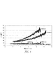
非線形比誘電率試験を用いて、表2の所定の実施例の、電界に対する誘電率の変動(非線形特性)を測定した。これらの試験結果は、図5に示されている。図5に見られるように、実施例1及び3は、電界の上昇に伴い、誘電率値が非線形的に上昇する。電界強度が5.5kV/mmまで上昇すると、誘電率値は、実施例1では24.1から140に上昇し、実施例2では21.7から120に上昇する。これらの実験条件では、比較例C1、C2及びC3は、非線形誘電特性を示さない。 Using a non-linear relative dielectric constant test, the variation (non-linear characteristic) of the dielectric constant with respect to the electric field of the predetermined examples in Table 2 was measured. These test results are shown in FIG. As can be seen in FIG. 5, in Examples 1 and 3, the dielectric constant value increases nonlinearly as the electric field increases. As the field strength increases to 5.5 kV / mm, the dielectric constant value increases from 24.1 to 140 in Example 1 and from 21.7 to 120 in Example 2. Under these experimental conditions, Comparative Examples C1, C2, and C3 do not exhibit nonlinear dielectric properties.
図6は、実施例1、3、4、及び5の誘電率データを示している。図6に見られるように、実施例1及び3と共に実施例4は、非線形誘電特性を示し、実施例5は、印加電解の範囲において非線形誘電特性を示さない。 FIG. 6 shows the dielectric constant data of Examples 1, 3, 4, and 5. As seen in FIG. 6, Example 4 together with Examples 1 and 3 show nonlinear dielectric properties, and Example 5 does not show nonlinear dielectric properties in the range of applied electrolysis.
表2に見られるように、比較例C4は同じBT及びC含有量を有する実施例3よりも、比較例C5は同じBT及びC含有量を有する実施例1よりも、いずれも低い電気的破壊強度値を有する。比較例C4の破壊強度は3.84kV/mm(97.6V/ミル)であり、比較例C5の誘電破壊強度は2.60kV/mm(66V/ミル)である。加えて、誘電率は、これらの比較例では、電界に対して、実施例1及び3よりも早く上昇する。対照的に、実施例1及び3は、誘電率が徐々に上昇すると共に、材料の誘電破壊に達するまで、極めて高い電解強度に耐えることができる(実施例1の誘電破壊は5.79V/mmであり、実施例3の誘電破壊は7.10kV/mmである)。 As can be seen in Table 2, Comparative Example C4 has a lower electrical breakdown than Example 3 with the same BT and C content, and Comparative Example C5 has a lower electrical breakdown than Example 1 with the same BT and C content. Has an intensity value. Comparative Example C4 has a breaking strength of 3.84 kV / mm (97.6 V / mil), and Comparative Example C5 has a dielectric breaking strength of 2.60 kV / mm (66 V / mil). In addition, the dielectric constant rises faster with respect to the electric field than in Examples 1 and 3 in these comparative examples. In contrast, Examples 1 and 3 can withstand very high electrolytic strength until the dielectric breakdown of the material is reached as the dielectric constant increases (the dielectric breakdown of Example 1 is 5.79 V / mm). The dielectric breakdown of Example 3 is 7.10 kV / mm).
実施例6〜8−異なるK値を有するフィラー
これらの実施例では、チタン酸バリウム粒子をシリカ、二酸化チタン、チタン酸カルシウム、及びチタン酸ストロンチウム粒子で置換した。各タイプの無機粒子30体積パーセントを炭素粉末3体積パーセントと粉砕した後、実施例1〜5について説明したようにしてシリコーンゴムディスクを調製した。続いて、これらのディスクのそれぞれの電気的特性を測定した。試験結果は、実施例3の試験結果と共に表3にまとめられている。加えて、実施例6〜8の非線形誘電特性を測定した。当該試験の結果を、図8に示す。
Examples 6-8-Fillers with different K values In these examples, barium titanate particles were replaced with silica, titanium dioxide, calcium titanate, and strontium titanate particles. After grinding 30 volume percent of each type of inorganic particles with 3 volume percent of carbon powder, silicone rubber discs were prepared as described for Examples 1-5. Subsequently, the electrical characteristics of each of these disks were measured. The test results are summarized in Table 3 together with the test results of Example 3. In addition, the nonlinear dielectric properties of Examples 6-8 were measured. The result of the test is shown in FIG.
実施例9
この実施例では、炭素粉末を18体積パーセントのアルミニウム粉末(サイズ10マイクロメートル)(1.5g/ccの密度を用いて計算)で置換した。Al粉末を24.5体積パーセントのチタン酸バリウムと粉砕した後に、実施例1〜5で説明したようにしてシリコーンゴムディスクを調製した。得られたディスクの誘電率(K)は20.8で、損失係数は0.022であった。
Example 9
In this example, the carbon powder was replaced with 18 volume percent aluminum powder (size 10 micrometers) (calculated using a density of 1.5 g / cc). After grinding the Al powder with 24.5 volume percent barium titanate, silicone rubber disks were prepared as described in Examples 1-5. The obtained disk had a dielectric constant (K) of 20.8 and a loss factor of 0.022.
実施例10
疎水性変性ナノシリカ粒子の調製:
コロイドシリカ(水中に固体16.06重量%、サイズ5nm)100グラムと、イソオクチルトリメトキシシラン(isoctyltrimethoxy silane)7.54グラムと、メチルトリメトキシシラン0.81グラムと、エタノールとメタノール(80:20重量/重量%)の溶媒ブレンド112.5グラムとの混合物を、500mLの三つ口フラスコ(Ace Glass(Vineland,NJ))に加えた。80℃に設定した油浴に、この混合物を含むフラスコを攪拌しながら4時間入れて、疎水性変性ナノシリカ粒子を調製した。この疎水性変性ナノシリカ粒子を結晶皿に移し、対流式オーブンで150℃にて2時間乾燥させた。
Example 10
Preparation of hydrophobically modified nanosilica particles:
100 grams of colloidal silica (16.06 wt% solids in water,
チタン酸バリウムフィラーのナノシリカ粒子による変性:
疎水性変性ナノシリカ粒子(0.75重量%)と(スパチュラを用いて)混合し、過剰なトルエンに分散させることによって、チタン酸バリウム粒子(粒径0.8〜2.1マイクロメートル)を変性させた。このチタン酸バリウムとナノシリカ粒子との混合物を一晩圧延してから、トルエンを150℃で蒸発させた。得られた粉末を大きなナルゲンボトルに移し、この粉末に4つの大きなセラミック大理石を加え、手で数分間振とうした。この手順によって、粒子の凝集が大きく低減したフィラー組成物が得られた。ナノシリカ粒子変性チタン酸バリウムの走査電子顕微鏡写真(SEM)は図3に示されている。
Modification of barium titanate filler with nano silica particles:
Modified barium titanate particles (particle size 0.8-2.1 micrometers) by mixing (using a spatula) with hydrophobically modified nanosilica particles (using a spatula) and dispersing in excess toluene I let you. The mixture of barium titanate and nanosilica particles was rolled overnight and then toluene was evaporated at 150 ° C. The resulting powder was transferred to a large Nargen bottle, and four large ceramic marbles were added to this powder and shaken by hand for several minutes. By this procedure, a filler composition with greatly reduced particle aggregation was obtained. A scanning electron micrograph (SEM) of the nanosilica particle modified barium titanate is shown in FIG.
実施例11:シリコーンゴム複合材の調製:
実施例1〜5で説明されているようにして、ナノシリカ粒子変性チタン酸バリウム(NS BT)に炭素粉末を蒸着させた。約25体積パーセントのNS BTと3.0体積パーセントの炭素粉末を合わせて、均一な分散体が得られるまで(裸眼で判断)、乳鉢と乳棒で5〜10分間粉砕した。DAC 150FVZという商品名でFlackTek,Inc.(Landrum、SC)から入手可能な「スピードミキサー」を用いて、粉砕した粉末混合物を62体積パーセントの液体シリコーンゴムと10体積パーセントのシリコーン油中で、3000rpmにて30秒間ブレンドした。続いて、得られたシリコーンゴム複合材を成形型(3×6×.07インチ(7.6cm×15.2cm×0.18cm))に注入し、160℃で10分間、部分的にプレス硬化させた。次いで、部分硬化させたスラブを成形型から外し、200℃で4時間、更に硬化させた。硬化スラブの断面のSEMには、NS BT粒子がシリコーンマトリックス全体にわたって均一に分布していることが示されている(図4)。
Example 11: Preparation of silicone rubber composite:
Carbon powder was evaporated onto nanosilica particle modified barium titanate (NS BT) as described in Examples 1-5. About 25 volume percent NSBT and 3.0 volume percent carbon powder were combined and ground with a mortar and pestle for 5-10 minutes until a uniform dispersion was obtained (as judged by the naked eye). Under the trade name DAC 150FVZ, FlackTek, Inc. The ground powder mixture was blended in 62 volume percent liquid silicone rubber and 10 volume percent silicone oil for 30 seconds at 3000 rpm using a “speed mixer” available from (Landrum, SC). Subsequently, the obtained silicone rubber composite was poured into a mold (3 × 6 × 0.07 inch (7.6 cm × 15.2 cm × 0.18 cm)) and partially press cured at 160 ° C. for 10 minutes. I let you. The partially cured slab was then removed from the mold and further cured at 200 ° C. for 4 hours. The SEM of the cross section of the cured slab shows that NSBT particles are evenly distributed throughout the silicone matrix (FIG. 4).
電気的及び機械的特性を割り出す目的で行う各試験では、3つのサンプルを用いた。これらの3つのサンプルの試験結果の範囲を以下に示す。 Three samples were used in each test conducted to determine the electrical and mechanical properties. The range of test results for these three samples is shown below.
電気的特性:
100HzにおいてASTM D150−98(2004)の試験手順に従うことによって、誘電率と損失係数の測定を行った。100HzにおいてASTM 257−07の試験手順に従うことによって、体積固有抵抗の測定を行った。ASTM D149−09の試験手順に従うことによって、誘電破壊強度の測定を行った。試験結果の範囲は以下のとおりである。
誘電率23〜30
損失係数<0.05
固有抵抗:1.4 E8〜E9オーム/m
誘電破壊強度180〜210V/ミル(7,086.61〜8,267.72kV/mm)の範囲
非線形比誘電率試験を用いて、インパルス状態における電界依存の比誘電率を25kVで測定した。当該試験の結果を、図9に示す。
Electrical characteristics:
The dielectric constant and loss factor were measured by following the test procedure of ASTM D150-98 (2004) at 100 Hz. Volume resistivity was measured by following the test procedure of ASTM 257-07 at 100 Hz. Dielectric breakdown strength was measured by following the test procedure of ASTM D149-09. The range of test results is as follows.
Dielectric constant 23-30
Loss factor <0.05
Specific resistance: 1.4 E8 to E9 ohm / m
Dielectric breakdown strength of 180 to 210 V / mil (7,086.61 to 8,267.72 kV / mm) range The electric field dependent relative dielectric constant in an impulse state was measured at 25 kV using a nonlinear relative dielectric constant test. The result of the test is shown in FIG.
機械的特性:
ASTM D412−06aの試験手順を用いることによって、引張り強度、破断までの伸び率、弾性率及び伸長永久歪を測定する。試験結果の範囲は以下のとおりである。
引張り強度:372〜498psi(2564.8〜3433.6kPa)
破断までの伸び:320〜410%
弾性率:
232〜255psi(1599.6〜1758.2kPa)@ 100%の伸び率
285〜429psi(1965.0〜2957.9kPa)@ 200%の伸び率
300〜479psi(2068.4〜3302.6kPa)@ 300%の伸び率
伸長永久歪9.4〜10.10%
Mechanical properties:
Measure tensile strength, elongation to break, modulus, and permanent set by using the test procedure of ASTM D412-06a. The range of test results is as follows.
Tensile strength: 372-498 psi (2564.8-3433.6 kPa)
Elongation to break: 320-410%
Elastic modulus:
232-255 psi (1599.6-1758.2 kPa) @ 100% elongation 285-429 psi (1965.0-2957.9 kPa) @ 200% elongation 300-479 psi (2068.4-3302.6 kPa) @ 300 % Elongation elongation set 9.4-10.10%
実施例11の320〜410%という破断までの伸び率と比較すると、実施例3(NS BT及びシリコーンオイルを含めずに作製)の破断までの伸び率は166%であった。 Compared with the elongation rate up to breakage of 320 to 410% in Example 11, the elongation rate up to breakage in Example 3 (made without including NSBT and silicone oil) was 166%.
Claims (2)
前記ポリマー材中に分散させたフィラー材と、を含む電気的ストレス制御物品における使用に適した組成物であって、前記フィラー材が無機粒子と不連続な配列の導電材とを含み、
前記導電材の少なくとも一部が、前記無機粒子と耐久性のある電気的接続状態にあり、前記耐久性のある電気的接続状態は、前記導電材の前記無機粒子への付加又は付着によって提供され、前記導電材の一部が前記ポリマー材中に分散しており、
前記無機粒子が、BaTiO 3 粒子、BaSrTiO 3 粒子、CaCu 3 Ti 4 O 12 粒子、SrTiO 3 粒子、及びこれらの混合物からなる群から選択され、
前記導電材が、カーボンブラック、カーボンナノチューブ、炭素粒子のクラスター、グラファイト、導電性コーティングを有する絶縁粒子、金属及び該金属の合金、並びにこれらの組み合わせからなる群から選択され、
前記無機粒子が、ナノシリカで変性されている、組成物。 A polymer material;
A composition suitable for use in an electrical stress control article comprising a filler material dispersed in the polymer material, the filler material comprising inorganic particles and a discontinuous arrangement of conductive materials,
At least a part of the conductive material is in a durable electrical connection state with the inorganic particles, and the durable electrical connection state is provided by addition or adhesion of the conductive material to the inorganic particles. , A part of the conductive material is dispersed in the polymer material,
The inorganic particles are selected from the group consisting of BaTiO 3 particles, BaSrTiO 3 particles, CaCu 3 Ti 4 O 12 particles, SrTiO 3 particles, and mixtures thereof;
The conductive material is selected from the group consisting of carbon black, carbon nanotubes, clusters of carbon particles, graphite, insulating particles having a conductive coating, metals and alloys of the metals, and combinations thereof;
A composition in which the inorganic particles are modified with nano silica.
前記導電材の少なくとも一部が、前記無機粒子と耐久性のある電気的接続状態にあり、前記耐久性のある電気的接続状態は、前記導電材の前記無機粒子への付加又は付着によって提供され、前記導電材の一部が前記ポリマー材中に分散しており、
前記無機粒子が、BaTiO 3 粒子、BaSrTiO 3 粒子、CaCu 3 Ti 4 O 12 粒子、SrTiO 3 粒子、及びこれらの混合物からなる群から選択され、
前記導電材が、カーボンブラック、カーボンナノチューブ、炭素粒子のクラスター、グラファイト、導電性コーティングを有する絶縁粒子、金属及び該金属の合金、並びにこれらの組み合わせからなる群から選択され、
前記無機粒子が、ナノシリカで変性されている、電気的ストレス制御デバイスを含む、物品。 An electrical stress control device comprising a filler material dispersed in a polymer material, the filler material comprising inorganic particles and a discontinuous array of conductive materials,
At least a part of the conductive material is in a durable electrical connection state with the inorganic particles, and the durable electrical connection state is provided by addition or adhesion of the conductive material to the inorganic particles. , A part of the conductive material is dispersed in the polymer material,
The inorganic particles are selected from the group consisting of BaTiO 3 particles, BaSrTiO 3 particles, CaCu 3 Ti 4 O 12 particles, SrTiO 3 particles, and mixtures thereof;
The conductive material is selected from the group consisting of carbon black, carbon nanotubes, clusters of carbon particles, graphite, insulating particles having a conductive coating, metals and alloys of the metals, and combinations thereof;
An article comprising an electrical stress control device, wherein the inorganic particles are modified with nanosilica.
Applications Claiming Priority (3)
| Application Number | Priority Date | Filing Date | Title |
|---|---|---|---|
| US28624709P | 2009-12-14 | 2009-12-14 | |
| US61/286,247 | 2009-12-14 | ||
| PCT/US2010/059213 WO2011081795A1 (en) | 2009-12-14 | 2010-12-07 | Dielectric material with non-linear dielectric constant |
Publications (3)
| Publication Number | Publication Date |
|---|---|
| JP2013513715A JP2013513715A (en) | 2013-04-22 |
| JP2013513715A5 JP2013513715A5 (en) | 2014-01-23 |
| JP5787898B2 true JP5787898B2 (en) | 2015-09-30 |
Family
ID=43661177
Family Applications (1)
| Application Number | Title | Priority Date | Filing Date |
|---|---|---|---|
| JP2012544606A Expired - Fee Related JP5787898B2 (en) | 2009-12-14 | 2010-12-07 | Dielectric material having nonlinear dielectric constant |
Country Status (10)
| Country | Link |
|---|---|
| US (3) | US8974706B2 (en) |
| EP (1) | EP2513913A1 (en) |
| JP (1) | JP5787898B2 (en) |
| KR (1) | KR101869985B1 (en) |
| CN (1) | CN102656646B (en) |
| CA (1) | CA2782792C (en) |
| MX (1) | MX2012006488A (en) |
| RU (1) | RU2540412C2 (en) |
| TW (1) | TWI529746B (en) |
| WO (1) | WO2011081795A1 (en) |
Families Citing this family (32)
| Publication number | Priority date | Publication date | Assignee | Title |
|---|---|---|---|---|
| CN103715647A (en) * | 2012-10-09 | 2014-04-09 | 泰科电子(上海)有限公司 | Cold shrinking type terminal for power cable |
| CN103849008B (en) * | 2012-11-29 | 2018-04-13 | 深圳先进技术研究院 | Hybrid particulates, polymer matrix composite and preparation method and application |
| MX2015009805A (en) | 2013-02-04 | 2015-10-29 | 3M Innovative Properties Co | Insulating composition, insulating article, preparation method and electrical cable accessory thereof. |
| US9352829B2 (en) | 2013-03-07 | 2016-05-31 | Bell Helicopter Textron Inc. | Aircraft with protective nanocoating |
| US8998124B2 (en) * | 2013-03-07 | 2015-04-07 | Bell Helicopter Textron Inc. | Aircraft with electrically conductive nanocoating |
| CN104046308B (en) * | 2013-03-15 | 2016-12-28 | 长春中科应化特种材料有限公司 | A kind of adhesive for electric stress relief and production method thereof |
| FR3003993B1 (en) * | 2013-03-29 | 2016-08-19 | Nexans | ELECTRICAL CABLE COMPRISING A GRADIENT LAYER OF ELECTRICAL PROPERTY |
| US9876342B2 (en) | 2013-09-25 | 2018-01-23 | 3M Innovative Properties Company | Compositions for electric field grading |
| CN106133271A (en) * | 2014-04-04 | 2016-11-16 | 国际壳牌研究有限公司 | Use the final insulated electric conductor reducing step formation after the heat treatment |
| RU2610900C2 (en) * | 2015-06-08 | 2017-02-17 | Федеральное государственное образовательное бюджетное учреждение высшего профессионального образования Московский технический университет связи и информатики (ФГОБУ ВПО МТУСИ) | Coaxial cable with nanotube insulation |
| RU2628756C2 (en) * | 2015-11-13 | 2017-08-22 | Открытое акционерное общество Всероссийский научно-исследовательский, проектно-конструкторский и технологический институт кабельной промышленности (ВНИИ КП) | Electric insulating material |
| DE102016205195A1 (en) * | 2016-02-02 | 2017-08-17 | Siemens Aktiengesellschaft | Shield ring for a transformer coil |
| US10438717B2 (en) | 2016-04-25 | 2019-10-08 | Eaton Intelligent Power Limited | Elastomer composites with high dielectric constant |
| WO2018102254A1 (en) | 2016-12-02 | 2018-06-07 | 3M Innovative Properties Company | Nonlinear composite compositions, methods of making the same, and articles including the same |
| WO2018144300A1 (en) * | 2017-01-31 | 2018-08-09 | 3M Innovative Properties Company | Multilayer stress control article and dry termination for medium and high voltage cable applications |
| WO2019097446A1 (en) | 2017-11-16 | 2019-05-23 | 3M Innovative Properties Company | Polymer matrix composites comprising functional particles and methods of making the same |
| KR20200098531A (en) | 2017-11-16 | 2020-08-20 | 쓰리엠 이노베이티브 프로퍼티즈 캄파니 | Method for manufacturing polymer matrix composite |
| CN111357061B (en) | 2017-11-16 | 2022-04-12 | 3M创新有限公司 | Polymer matrix composites comprising dielectric particles and methods of making the same |
| US10836873B2 (en) | 2017-11-16 | 2020-11-17 | 3M Innovative Properties Company | Polymer matrix composites comprising thermally insulating particles and methods of making the same |
| US10913834B2 (en) | 2017-11-16 | 2021-02-09 | 3M Innovative Properties Company | Polymer matrix composites comprising indicator particles and methods of making the same |
| US10927228B2 (en) | 2017-11-16 | 2021-02-23 | 3M Innovative Properties Company | Polymer matrix composites comprising intumescent particles and methods of making the same |
| WO2019180621A2 (en) | 2018-03-22 | 2019-09-26 | 3M Innovative Properties Company | Charge-modified particles and methods of making the same |
| US11492495B2 (en) | 2018-03-22 | 2022-11-08 | 3M Innovative Properties Company | Modified aluminum nitride particles and methods of making the same |
| US11873403B2 (en) | 2018-05-16 | 2024-01-16 | 3M Innovative Properties Company | Electric field grading composition, methods of making the same, and composite articles including the same |
| WO2020061988A1 (en) | 2018-09-28 | 2020-04-02 | Dow Silicones Corporation | Liquid silicone rubber composition |
| RU2713223C1 (en) * | 2018-11-29 | 2020-02-04 | Федеральное государственное бюджетное образовательное учреждение высшего образования "Саратовский государственный технический университет имени Гагарина Ю.А." (СГТУ имени Гагарина Ю.А.) | Dielectric elastomer composite material, method of its production and application |
| CN109796765A (en) * | 2019-01-09 | 2019-05-24 | 清华大学 | The nonlinear conductance composite materials of high-mechanical property |
| EP3942574B1 (en) | 2019-03-18 | 2023-11-15 | 3M Innovative Properties Company | Multilayer electric field grading article, methods of making the same, and articles including the same |
| RU2721173C1 (en) * | 2020-01-14 | 2020-05-18 | Общество с ограниченной ответственностью "Завод герметизирующих материалов" | Polymer composition for controlling electric field intensity |
| RU2750120C1 (en) * | 2020-12-09 | 2021-06-22 | Общество с ограниченной ответственностью «Завод герметизирующих материалов» | Polymer compound for regulating electric field strength |
| RU208640U1 (en) * | 2021-10-22 | 2021-12-28 | Открытое акционерное общество " Иркутсккабель" | Power cable with polypropylene insulation |
| US20240110035A1 (en) * | 2022-09-29 | 2024-04-04 | Te Connectivity Solutions Gmbh | Electrical stress grading compositions and devices including the same |
Family Cites Families (26)
| Publication number | Priority date | Publication date | Assignee | Title |
|---|---|---|---|---|
| US3666876A (en) | 1970-07-17 | 1972-05-30 | Exxon Research Engineering Co | Novel compositions with controlled electrical properties |
| GB1470501A (en) * | 1973-03-20 | 1977-04-14 | Raychem Ltd | Polymer compositions for electrical use |
| DE2821017C3 (en) * | 1978-05-12 | 1981-02-05 | Minnesota Mining And Manufacturing Co., Saint Paul, Minn. (V.St.A.) | Dielectric material for influencing electrical fields and its use in field control elements |
| JPS5557426A (en) * | 1978-10-26 | 1980-04-28 | Nitto Electric Ind Co Ltd | Insulative tape or film |
| JPS5599984A (en) * | 1979-01-25 | 1980-07-30 | Showa Electric Wire & Cable Co Ltd | Autohesive tape with electric field relaxation effect |
| BR8101228A (en) * | 1980-03-03 | 1981-09-08 | Minnesota Mining & Mfg | ELASTOMERIC COMPOSITION, ELASTOMERIC TUBULAR ARTICLE AND ARTICLE FOR SEAMLESS USE AND TERMINATION OF ELECTRIC POWER CABLES |
| US4363842A (en) * | 1981-03-02 | 1982-12-14 | Minnesota Mining And Manufacturing Company | Elastomeric pre-stretched tubes for providing electrical stress control |
| GB8303462D0 (en) * | 1983-02-08 | 1983-03-16 | Raychem Gmbh | Electrical stress control |
| US4726991A (en) * | 1986-07-10 | 1988-02-23 | Eos Technologies Inc. | Electrical overstress protection material and process |
| EP0476541A3 (en) | 1990-09-18 | 1992-05-13 | Siemens Aktiengesellschaft | Process for the production of electro-ceramic components from highly dispersed ceramic masses prepared by coprecipitation |
| US6268054B1 (en) * | 1997-02-18 | 2001-07-31 | Cabot Corporation | Dispersible, metal oxide-coated, barium titanate materials |
| US6251513B1 (en) * | 1997-11-08 | 2001-06-26 | Littlefuse, Inc. | Polymer composites for overvoltage protection |
| CN1226752C (en) * | 2001-01-29 | 2005-11-09 | 捷时雅株式会社 | Composite particle for dielectrics, ultramicro particulate composite resin particle, composition for forming dielectrics and use thereof |
| JP5250923B2 (en) * | 2001-07-13 | 2013-07-31 | Jsr株式会社 | Ultrafine composite resin particles, composition for forming a dielectric, and electronic component |
| ATE499691T1 (en) * | 2001-07-02 | 2011-03-15 | Abb Schweiz Ag | POLYMER COMPOUND WITH NON-LINEAR CURRENT-VOLTAGE CHARACTERISTICS AND METHOD FOR PRODUCING A POLYMER COMPOUND |
| SE525492C2 (en) * | 2002-10-22 | 2005-03-01 | Abb Research Ltd | Field-controlling polymer matrix provided with filling |
| CA2409524A1 (en) * | 2002-10-23 | 2004-04-23 | Hydro-Quebec | Particles consisting of graphite-based cores and covered by at least one continuous or discontinuous layer, production processes and uses for such particles |
| EP1585146B1 (en) * | 2004-04-06 | 2008-08-06 | Abb Research Ltd. | Nonlinear electrical material for high and medium voltage applications |
| US7723408B2 (en) * | 2005-02-16 | 2010-05-25 | Georgia Tech Research Corporation | Composite materials having low filler percolation thresholds and methods of controlling filler interconnectivity |
| FR2889850B1 (en) * | 2005-08-19 | 2007-11-02 | Rhodia Chimie Sa | SILICONE COATING OF LOW DIELECTRIC CONSTANT, PROCESS FOR PREPARATION AND APPLICATION TO INTEGRATED CIRCUITS |
| US7741396B2 (en) * | 2005-11-23 | 2010-06-22 | General Electric Company | Composites having tunable dielectric constants, methods of manufacture thereof, and articles comprising the same |
| US20080006795A1 (en) * | 2006-07-10 | 2008-01-10 | General Electric Company | Article and associated device |
| US20080006796A1 (en) * | 2006-07-10 | 2008-01-10 | General Electric Company | Article and associated method |
| US20120119168A9 (en) * | 2006-11-21 | 2012-05-17 | Robert Fleming | Voltage switchable dielectric materials with low band gap polymer binder or composite |
| CN101225245A (en) | 2008-01-31 | 2008-07-23 | 上海卓越纳米新材料股份有限公司 | Method for preparing core-shell silicon dioxide coated nano calcium carbonate |
| CN101440180B (en) * | 2008-12-26 | 2011-04-20 | 哈尔滨理工大学 | Polyolefin based non-linear dielectric material with non-linear dielectric constant and non-linear conductivity |
-
2010
- 2010-12-07 JP JP2012544606A patent/JP5787898B2/en not_active Expired - Fee Related
- 2010-12-07 CA CA2782792A patent/CA2782792C/en not_active Expired - Fee Related
- 2010-12-07 CN CN201080056831.0A patent/CN102656646B/en not_active Expired - Fee Related
- 2010-12-07 US US12/962,022 patent/US8974706B2/en not_active Expired - Fee Related
- 2010-12-07 KR KR1020127017978A patent/KR101869985B1/en active IP Right Grant
- 2010-12-07 RU RU2012122897/07A patent/RU2540412C2/en not_active IP Right Cessation
- 2010-12-07 WO PCT/US2010/059213 patent/WO2011081795A1/en active Application Filing
- 2010-12-07 EP EP10793103A patent/EP2513913A1/en not_active Withdrawn
- 2010-12-07 MX MX2012006488A patent/MX2012006488A/en unknown
- 2010-12-13 TW TW099143559A patent/TWI529746B/en not_active IP Right Cessation
-
2014
- 2014-12-23 US US14/581,325 patent/US9349498B2/en not_active Expired - Fee Related
- 2014-12-23 US US14/581,410 patent/US9390833B2/en not_active Expired - Fee Related
Also Published As
| Publication number | Publication date |
|---|---|
| EP2513913A1 (en) | 2012-10-24 |
| CA2782792C (en) | 2019-06-18 |
| US20110140052A1 (en) | 2011-06-16 |
| CN102656646B (en) | 2016-08-10 |
| KR101869985B1 (en) | 2018-06-22 |
| US9349498B2 (en) | 2016-05-24 |
| US20150108414A1 (en) | 2015-04-23 |
| CN102656646A (en) | 2012-09-05 |
| CA2782792A1 (en) | 2011-07-07 |
| US8974706B2 (en) | 2015-03-10 |
| JP2013513715A (en) | 2013-04-22 |
| US20150137047A1 (en) | 2015-05-21 |
| TW201131585A (en) | 2011-09-16 |
| US9390833B2 (en) | 2016-07-12 |
| RU2012122897A (en) | 2014-01-27 |
| RU2540412C2 (en) | 2015-02-10 |
| MX2012006488A (en) | 2012-07-03 |
| TWI529746B (en) | 2016-04-11 |
| WO2011081795A1 (en) | 2011-07-07 |
| KR20120104318A (en) | 2012-09-20 |
Similar Documents
| Publication | Publication Date | Title |
|---|---|---|
| JP5787898B2 (en) | Dielectric material having nonlinear dielectric constant | |
| US7618550B2 (en) | Polymer compound with nonlinear current-voltage characteristic and process for producing a polymer compound | |
| Yuan et al. | Fabrication and dielectric properties of advanced high permittivity polyaniline/poly (vinylidene fluoride) nanohybrid films with high energy storage density | |
| Zhou et al. | Thermoplastic polypropylene/aluminum nitride nanocomposites with enhanced thermal conductivity and low dielectric loss | |
| Ren et al. | Silver nanoparticle-modified alumina microsphere hybrid composites for enhanced energy density and thermal conductivity | |
| RU2404468C2 (en) | Field control tape based on varistor | |
| JP2017531296A (en) | Dielectric material with improved breakdown strength | |
| WO2012006416A2 (en) | High dielectric constant ceramic filler particles, composites and methods for making same | |
| US11043797B2 (en) | Cable fitting for HVDC cables | |
| Abdelmalik et al. | Low Dielectric Loss Epoxy Polymer Composite from Periwinkle Shell Microparticles. | |
| Cao et al. | Core-shell structured Ag@ PDA nanowires and BT@ PDA nanoparticles for three-phase flexible polymer nanocomposites with excellent dielectric properties | |
| Nakamura et al. | Experimental investigation on erosion resistance and hydrophobicity of silicone rubber nanocomposite | |
| US20230018717A1 (en) | Particulate filler, preparation and use thereof | |
| Feng et al. | Significantly reduced dielectric loss and conductivity in polymer-based nano-composites from a suppressed interface coulomb force | |
| Yang et al. | Thermal and electrical properties of BNNPs/TiO 2-Epoxy three-phase nanocomposites | |
| Jin et al. | Dielectric nanocomposite with high dielectric permittivity and low dielectric loss | |
| US20230407052A1 (en) | Method for variably adjusting the electrical insulating properties of varistor-containing materials | |
| Hamzah et al. | Effect of Hybrid Fillers in PP/EPDM Nanocomposites for Electrical Insulator Application. | |
| Al-Gheilani et al. | Electrical and Thermomechanical Properties of Hybrid Materials based on ZnO and BaTiO 3 Nano Particles | |
| JPH11199757A (en) | Conductive epoxy resin composition |
Legal Events
| Date | Code | Title | Description |
|---|---|---|---|
| A521 | Request for written amendment filed |
Free format text: JAPANESE INTERMEDIATE CODE: A523 Effective date: 20131128 |
|
| A621 | Written request for application examination |
Free format text: JAPANESE INTERMEDIATE CODE: A621 Effective date: 20131128 |
|
| A977 | Report on retrieval |
Free format text: JAPANESE INTERMEDIATE CODE: A971007 Effective date: 20140625 |
|
| A131 | Notification of reasons for refusal |
Free format text: JAPANESE INTERMEDIATE CODE: A131 Effective date: 20140701 |
|
| A521 | Request for written amendment filed |
Free format text: JAPANESE INTERMEDIATE CODE: A523 Effective date: 20140930 |
|
| A131 | Notification of reasons for refusal |
Free format text: JAPANESE INTERMEDIATE CODE: A131 Effective date: 20141028 |
|
| A131 | Notification of reasons for refusal |
Free format text: JAPANESE INTERMEDIATE CODE: A131 Effective date: 20150310 |
|
| A521 | Request for written amendment filed |
Free format text: JAPANESE INTERMEDIATE CODE: A523 Effective date: 20150609 |
|
| TRDD | Decision of grant or rejection written | ||
| A01 | Written decision to grant a patent or to grant a registration (utility model) |
Free format text: JAPANESE INTERMEDIATE CODE: A01 Effective date: 20150630 |
|
| A61 | First payment of annual fees (during grant procedure) |
Free format text: JAPANESE INTERMEDIATE CODE: A61 Effective date: 20150728 |
|
| R150 | Certificate of patent or registration of utility model |
Ref document number: 5787898 Country of ref document: JP Free format text: JAPANESE INTERMEDIATE CODE: R150 |
|
| LAPS | Cancellation because of no payment of annual fees |