JP5786966B2 - COMMUNICATION METHOD, COMMUNICATION TERMINAL, AND BASE STATION DEVICE - Google Patents

COMMUNICATION METHOD, COMMUNICATION TERMINAL, AND BASE STATION DEVICE Download PDF

Info

Publication number
JP5786966B2
JP5786966B2 JP2013555068A JP2013555068A JP5786966B2 JP 5786966 B2 JP5786966 B2 JP 5786966B2 JP 2013555068 A JP2013555068 A JP 2013555068A JP 2013555068 A JP2013555068 A JP 2013555068A JP 5786966 B2 JP5786966 B2 JP 5786966B2
Authority
JP
Japan
Prior art keywords
terminal
coverage hole
base station
hole
unit
Prior art date
Legal status (The legal status is an assumption and is not a legal conclusion. Google has not performed a legal analysis and makes no representation as to the accuracy of the status listed.)
Expired - Fee Related
Application number
JP2013555068A
Other languages
Japanese (ja)
Other versions
JPWO2013111309A1 (en
Inventor
横山 仁
仁 横山
Current Assignee (The listed assignees may be inaccurate. Google has not performed a legal analysis and makes no representation or warranty as to the accuracy of the list.)
Fujitsu Ltd
Original Assignee
Fujitsu Ltd
Priority date (The priority date is an assumption and is not a legal conclusion. Google has not performed a legal analysis and makes no representation as to the accuracy of the date listed.)
Filing date
Publication date
Application filed by Fujitsu Ltd filed Critical Fujitsu Ltd
Publication of JPWO2013111309A1 publication Critical patent/JPWO2013111309A1/en
Application granted granted Critical
Publication of JP5786966B2 publication Critical patent/JP5786966B2/en
Expired - Fee Related legal-status Critical Current
Anticipated expiration legal-status Critical

Links

Images

Classifications

    • HELECTRICITY
    • H04ELECTRIC COMMUNICATION TECHNIQUE
    • H04WWIRELESS COMMUNICATION NETWORKS
    • H04W24/00Supervisory, monitoring or testing arrangements
    • H04W24/04Arrangements for maintaining operational condition
    • HELECTRICITY
    • H04ELECTRIC COMMUNICATION TECHNIQUE
    • H04WWIRELESS COMMUNICATION NETWORKS
    • H04W4/00Services specially adapted for wireless communication networks; Facilities therefor
    • H04W4/02Services making use of location information
    • HELECTRICITY
    • H04ELECTRIC COMMUNICATION TECHNIQUE
    • H04WWIRELESS COMMUNICATION NETWORKS
    • H04W4/00Services specially adapted for wireless communication networks; Facilities therefor
    • H04W4/02Services making use of location information
    • H04W4/029Location-based management or tracking services
    • HELECTRICITY
    • H04ELECTRIC COMMUNICATION TECHNIQUE
    • H04WWIRELESS COMMUNICATION NETWORKS
    • H04W24/00Supervisory, monitoring or testing arrangements
    • H04W24/10Scheduling measurement reports ; Arrangements for measurement reports

Description

本発明は、通信端末が基地局装置を介して行う通信に関する。   The present invention relates to communication performed by a communication terminal via a base station device.

携帯電話システムの変更や、災害などにより壊れたシステムの復旧の際に、新たな基地局の設置が行われる。このような場合、基地局の設置が終了するまでは、携帯電話と基地局が通信できない領域であるカバレッジホールが発生することがある。そこで、カバレッジホールを解消するために、Minimization of Drive Test(MDT)が開発されている。MDTを用いるシステムでは、カバレッジホールが特定され、特定されたカバレッジホールを解消するためにアンテナの調整などが行われる。   A new base station is installed when a mobile phone system is changed or a system that has been damaged due to a disaster is restored. In such a case, a coverage hole, which is an area where the mobile phone and the base station cannot communicate, may occur until the installation of the base station is completed. Therefore, a Minimization of Drive Test (MDT) has been developed to eliminate the coverage hole. In a system using MDT, a coverage hole is specified, and antenna adjustment or the like is performed in order to eliminate the specified coverage hole.

通信が困難である領域の検出に関連する技術として、ハンドオーバ時に無線回線障害地点を判別可能とするシステムも考案されている。このシステムでは、第1のセルで回線断となり、回線断が起こった時刻から予め定められた時間内もしくは移動距離内で第2のセルと再接続した場合、移動端末は基地局に第1のセルの情報と第2のセルの情報のうち少なくとも一方を報告する。   As a technique related to detection of an area where communication is difficult, a system has been devised in which a wireless channel failure point can be determined at the time of handover. In this system, when the line is disconnected in the first cell, and the mobile terminal reconnects to the second cell within a predetermined time or movement distance from the time when the line disconnection occurs, the mobile terminal transmits the first to the base station. At least one of the cell information and the second cell information is reported.

国際公開第2009/060935号International Publication No. 2009/060935

特定されたカバレッジホールを消滅させるためにアンテナ等の調整を行ったとしても、システムの整備中で基地局の設置数が足りていない場合、カバレッジホールを解消できないことがある。   Even if the antennas and the like are adjusted in order to eliminate the specified coverage hole, the coverage hole may not be eliminated if the number of base stations installed is insufficient during system maintenance.

本発明は、ユーザにとってカバレッジホールを避けて通信することが容易なシステムを提供することを目的とする。   An object of the present invention is to provide a system that allows a user to easily communicate while avoiding a coverage hole.

実施形態にかかる通信方法では、端末が基地局を介して通信する有線ネットワークに含まれる通信装置は、通信が可能な強度の電波を前記端末が受信できない領域であるカバレッジホールの位置を特定する。次に、前記カバレッジホールに近接する可能性がある端末であるホール近接端末が決定される。さらに、前記ホール近接端末に、前記カバレッジホールの位置を特定可能な情報であるホール情報を通知する通知メッセージが送信される。   In the communication method according to the embodiment, a communication device included in a wired network with which a terminal communicates via a base station specifies the position of a coverage hole, which is an area where the terminal cannot receive radio waves having a communicable intensity. Next, a hole proximity terminal that is a terminal that may be close to the coverage hole is determined. Further, a notification message for notifying hole information, which is information capable of specifying the position of the coverage hole, is transmitted to the hole proximity terminal.

ユーザは、端末で受信されたホール情報に基づいて、カバレッジホールを避けて通信することが容易になる。   The user can easily communicate while avoiding the coverage hole based on the hole information received by the terminal.

実施形態にかかる通信方法の例を示す図である。It is a figure which shows the example of the communication method concerning embodiment. 第1の実施形態で動作する装置の構成の例を説明する図である。It is a figure explaining the example of a structure of the apparatus which operate | moves by 1st Embodiment. ホール情報データベースの例を示す図である。It is a figure which shows the example of a hall information database. 位置情報データベースの例を示す図である。It is a figure which shows the example of a positional infomation database. 装置のハードウェア構成の例を説明する図である。It is a figure explaining the example of the hardware constitutions of an apparatus. カバレッジホールと端末装置の位置関係の例を表す図である。It is a figure showing the example of the positional relationship of a coverage hole and a terminal device. メッセージフォーマットの例を示す図である。It is a figure which shows the example of a message format. カバレッジホールが改善できないと判定された後に行われる処理の例を示すシーケンス図である。It is a sequence diagram which shows the example of the process performed after it determines with a coverage hole not being improved. 算出部での計算結果と注意喚起を行うかの判定結果の例を示す。The calculation result in a calculation part and the example of the determination result of whether alerting is performed are shown. ホール通知を受信した端末装置の動作の例を説明するフローチャートである。It is a flowchart explaining the example of operation | movement of the terminal device which received the hall | hole notification. 第2の実施形態で動作する装置の構成の例を説明する図である。It is a figure explaining the example of a structure of the apparatus which operate | moves by 2nd Embodiment. 第2の実施形態において、カバレッジホールが改善できないと判定された後に行われる処理の例を示すシーケンス図である。In a 2nd embodiment, it is a sequence figure showing an example of processing performed after it is judged that a coverage hole cannot be improved. メッセージフォーマットの例を示す図である。It is a figure which shows the example of a message format. カバレッジホールの位置を通知されたときの基地局の処理の例を説明するフローチャートである。It is a flowchart explaining the example of a process of the base station when the position of a coverage hole is notified. カバレッジホールの位置を通知された端末装置の動作の例を説明するフローチャートである。It is a flowchart explaining the example of operation | movement of the terminal device notified of the position of the coverage hole. 第3の実施形態で動作する装置の構成の例を説明する図である。It is a figure explaining the example of a structure of the apparatus which operate | moves by 3rd Embodiment. メッセージフォーマットの例を示す図である。It is a figure which shows the example of a message format. 第3の実施形態において、カバレッジホールを縮小できないと判定された後に行われる処理の例を示すシーケンス図である。In a 3rd embodiment, it is a sequence figure showing an example of processing performed after it is judged that a coverage hole cannot be reduced. カバレッジホールの位置を通知されたときのMMEの処理の例を説明するフローチャートである。It is a flowchart explaining the example of a process of MME when the position of a coverage hole is notified. カバレッジホールの位置を通知された端末装置の動作の例を説明するフローチャートである。It is a flowchart explaining the example of operation | movement of the terminal device notified of the position of the coverage hole. 第4の実施形態にかかるシステムの例を示す図である。It is a figure which shows the example of the system concerning 4th Embodiment. アプリケーションサーバの構成の例を示す図である。It is a figure which shows the example of a structure of an application server. 第4の実施形態において、カバレッジホールを縮小できないと判定された後に行われる処理の例を示すシーケンス図である。In a 4th embodiment, it is a sequence figure showing an example of processing performed after it is judged that a coverage hole cannot be reduced. 通知メッセージのフォーマットの例を示す図である。It is a figure which shows the example of a format of a notification message. カバレッジホールの位置を通知された端末装置の動作の例を説明するフローチャートである。It is a flowchart explaining the example of operation | movement of the terminal device notified of the position of the coverage hole.

図1は、実施形態にかかる通信方法の例を示す。図1は、LTE(Long Term Evolution)ネットワークの例を示している。端末装置10aおよび10bは、基地局20を介して通信先の装置と通信するものとする。基地局20は、有線ネットワークに接続されており、有線ネットワークには、Mobility Management Equipment(MME)30、Element Manager(EM)40、MDT管理サーバ50、位置情報サーバ80が含まれている。   FIG. 1 shows an example of a communication method according to the embodiment. FIG. 1 shows an example of an LTE (Long Term Evolution) network. The terminal devices 10a and 10b communicate with a communication destination device via the base station 20. The base station 20 is connected to a wired network, and the wired network includes a mobility management equipment (MME) 30, an element manager (EM) 40, an MDT management server 50, and a location information server 80.

端末装置10aはユーザAの端末であり、端末装置10bはユーザBの端末であるとする。端末装置10aの位置はユーザAの移動に伴って変化し、端末装置10bの位置はユーザBの移動に伴って変化するものとする。各端末装置10は、位置情報サーバ80に現在の位置を通知するものとし、位置情報サーバ80は、端末装置10の位置情報を端末装置10の識別子と対応付けて保持しているものとする。また、この例では、ユーザAはカバレッジホール1の周辺やカバレッジホール1の中を移動するため、端末装置10aは複数回にわたってカバレッジホール1に入ることがあるものとする。   The terminal device 10a is a user A terminal, and the terminal device 10b is a user B terminal. The position of the terminal device 10a changes with the movement of the user A, and the position of the terminal device 10b changes with the movement of the user B. Each terminal apparatus 10 notifies the position information server 80 of the current position, and the position information server 80 retains the position information of the terminal apparatus 10 in association with the identifier of the terminal apparatus 10. In this example, since the user A moves around the coverage hole 1 or in the coverage hole 1, the terminal device 10a may enter the coverage hole 1 multiple times.

まず、端末装置10aは、ユーザAの移動に伴って、カバレッジホール1を縦断するとする。端末装置10aはカバレッジホール1に入ると基地局20と通信できないが、カバレッジホール1から抜けると基地局20との間の通信を再開する。さらに、端末装置10aは、通信が途切れた位置を特定する情報を含む通知をMDT管理サーバ50に送信する。以下の説明では、通信が途切れた位置を特定する情報を含む通知のことを、Radio Link Failure(RLF)通知と記載することがある。ここで、RLF通知は、端末装置10と基地局20の通信が途切れた位置を示すので、カバレッジホール1の位置を示す情報であるといえる。RLF通知は、基地局20、EM40を介してMDT管理サーバ50に受信される。   First, it is assumed that the terminal device 10a traverses the coverage hole 1 as the user A moves. The terminal device 10a cannot communicate with the base station 20 when entering the coverage hole 1, but resumes communication with the base station 20 when leaving the coverage hole 1. Furthermore, the terminal device 10a transmits a notification including information for specifying a position where communication is interrupted to the MDT management server 50. In the following description, a notification including information specifying a position where communication is interrupted may be referred to as a Radio Link Failure (RLF) notification. Here, the RLF notification indicates information indicating the position of the coverage hole 1 because it indicates the position where the communication between the terminal apparatus 10 and the base station 20 is interrupted. The RLF notification is received by the MDT management server 50 via the base station 20 and the EM 40.

MDT管理サーバ50は、RLF通知に含まれている情報からカバレッジホール1の位置を特定し、カバレッジホール1を小さくするために、基地局20のアンテナの設定に用いられるパラメータを計算する。MDT管理サーバ50は、計算したパラメータを基地局20に通知する。基地局20は、MDT管理サーバ50から通知されたパラメータを用いてアンテナを調整する。   The MDT management server 50 identifies the position of the coverage hole 1 from the information included in the RLF notification, and calculates parameters used for setting the antenna of the base station 20 in order to reduce the coverage hole 1. The MDT management server 50 notifies the calculated parameters to the base station 20. The base station 20 adjusts the antenna using the parameter notified from the MDT management server 50.

このとき、アンテナの調整が行われてもカバレッジホール1が消滅せず、端末装置10aが再度、カバレッジホール1に入ったとする。すると、端末装置10aは、前述のとおり、基地局20との通信が再開したときに、基地局20を介してMDT管理サーバ50にRLF通知を送信する。   At this time, it is assumed that the coverage hole 1 does not disappear even if the antenna is adjusted, and the terminal device 10a enters the coverage hole 1 again. Then, as described above, the terminal device 10a transmits an RLF notification to the MDT management server 50 via the base station 20 when communication with the base station 20 is resumed.

MDT管理サーバ50は、基地局20でのパラメータの変更を行ったカバレッジホール1についてのRLF通知を、再度、受信すると、そのカバレッジホール1を小さくすることができないと判定する。なお、カバレッジホール1を小さくすることができるかの判定が行われる前に、基地局20のパラメータが変更される回数は、実装に応じて任意に変更されるものとする。   When the MDT management server 50 receives again the RLF notification for the coverage hole 1 for which the parameter has been changed in the base station 20, it determines that the coverage hole 1 cannot be reduced. Note that the number of times the parameters of the base station 20 are changed before the determination of whether the coverage hole 1 can be reduced is arbitrarily changed according to the implementation.

MDT管理サーバ50は、小さくすることができないカバレッジホール1を検出すると、そのカバレッジホール1の位置を、カバレッジホール1の周辺に位置する端末装置10に通知する。このとき、MDT管理サーバ50は、カバレッジホール1の周辺に位置する端末装置10を位置情報サーバ80に問い合わせる。位置情報サーバ80は、カバレッジホール1からの距離が第1の閾値以下の端末装置10を、カバレッジホール1の周辺に位置すると判定する。ここでは、カバレッジホール1の周辺に位置する端末装置として、端末装置10aと端末装置10bがMDT管理サーバ50に通知されたものとする。以下の記載では、カバレッジホール1の周辺に位置する端末装置を「ホール近接端末」と記載することがある。MDT管理サーバ50は、端末装置10aと端末装置10bに、カバレッジホール1の位置を通知する。   When the MDT management server 50 detects the coverage hole 1 that cannot be reduced, the MDT management server 50 notifies the terminal device 10 located around the coverage hole 1 of the position of the coverage hole 1. At this time, the MDT management server 50 inquires of the location information server 80 about the terminal device 10 located around the coverage hole 1. The location information server 80 determines that the terminal device 10 whose distance from the coverage hole 1 is equal to or less than the first threshold is located around the coverage hole 1. Here, it is assumed that the terminal device 10 a and the terminal device 10 b are notified to the MDT management server 50 as terminal devices located around the coverage hole 1. In the following description, a terminal device located around the coverage hole 1 may be referred to as a “hole proximity terminal”. The MDT management server 50 notifies the position of the coverage hole 1 to the terminal device 10a and the terminal device 10b.

端末装置10bは、MDT管理サーバ50からカバレッジホール1の位置が通知されると、カバレッジホール1の位置を記憶し、端末装置10bの位置とカバレッジホール1の位置の間の距離を定期的に求める。端末装置10bとカバレッジホール1の間の距離が第2の閾値以下となると、端末装置10bは、ユーザBが認識できるような方法で警告情報を出力する。例えば、端末装置10bは、ディスプレイにカバレッジホール1までの距離が近いことを通知する情報を表示することができる。端末装置10aも端末装置10bと同様に動作する。   When the location of the coverage hole 1 is notified from the MDT management server 50, the terminal device 10b stores the location of the coverage hole 1, and periodically obtains the distance between the location of the terminal device 10b and the location of the coverage hole 1. . When the distance between the terminal device 10b and the coverage hole 1 is equal to or smaller than the second threshold value, the terminal device 10b outputs warning information by a method that can be recognized by the user B. For example, the terminal device 10b can display information notifying that the distance to the coverage hole 1 is short on the display. The terminal device 10a operates similarly to the terminal device 10b.

なお、カバレッジホール1の位置の通知は、基地局もしくはMME30によって行われても良い。この場合、基地局は、基地局に接続している端末装置10にカバレッジホール1の位置を通知することができる。また、MME30は、MME30に接続されている端末装置10にカバレッジホール1の位置を通知することができる。   The notification of the position of the coverage hole 1 may be performed by the base station or the MME 30. In this case, the base station can notify the terminal device 10 connected to the base station of the position of the coverage hole 1. Further, the MME 30 can notify the terminal device 10 connected to the MME 30 of the position of the coverage hole 1.

このように、実施形態にかかる方法が適用されると、改善できないと判定されたカバレッジホール1に端末装置10が近づいたときに、端末装置10のユーザに警告が出されるため、ユーザは、カバレッジホールを避けて通信しやすくなる。   Thus, when the method according to the embodiment is applied, a warning is issued to the user of the terminal device 10 when the terminal device 10 approaches the coverage hole 1 that is determined not to be improved. It becomes easy to communicate avoiding the hall.

<第1の実施形態>
以下の記載では、第1の閾値と第2の閾値の区別を容易にするために、第1の閾値を「観測エリア閾値」、第2の閾値を「注意喚起エリア閾値」と記載することがあるものとする。これらの閾値は、予め、MDT管理サーバ50に記憶されているものとする。
<First Embodiment>
In the following description, in order to facilitate the distinction between the first threshold value and the second threshold value, the first threshold value may be described as an “observation area threshold value” and the second threshold value as an “attention area threshold value”. It shall be. These threshold values are stored in the MDT management server 50 in advance.

〔装置構成〕
図2は、第1の実施形態で動作する装置の構成の例を示す。端末装置10は、無線部13、RLF生成部14、算出部15、注意喚起部16、位置検出部17、位置情報生成部18を備える。また、無線部13は無線送信部11と無線受信部12を有する。無線送信部11と無線受信部12は、基地局20との間の無線通信を行う。RLF生成部14は、端末装置10と基地局20との通信に失敗した位置と、通信が途切れる前に通信していた基地局20を識別する識別子を含むRLF通知を生成する。RLF生成部14で生成されたRLF通知は、無線送信部11から基地局20に向けて送信され、基地局20からMDT管理サーバ50に送信される。
〔Device configuration〕
FIG. 2 shows an example of the configuration of an apparatus that operates in the first embodiment. The terminal device 10 includes a wireless unit 13, an RLF generation unit 14, a calculation unit 15, an attention drawing unit 16, a position detection unit 17, and a position information generation unit 18. The wireless unit 13 includes a wireless transmission unit 11 and a wireless reception unit 12. The wireless transmission unit 11 and the wireless reception unit 12 perform wireless communication with the base station 20. The RLF generating unit 14 generates an RLF notification including a position where the communication between the terminal device 10 and the base station 20 has failed and an identifier for identifying the base station 20 that communicated before the communication was interrupted. The RLF notification generated by the RLF generation unit 14 is transmitted from the wireless transmission unit 11 toward the base station 20 and is transmitted from the base station 20 to the MDT management server 50.

算出部15は、カバレッジホール1の位置が端末装置10に通知されると、その情報を記憶する。さらに、算出部15は、カバレッジホール1と端末装置10の間の距離を計算し、計算結果を注意喚起部16に出力する。注意喚起部16は、端末装置10に通知された注意喚起エリア閾値(第2の閾値)を保持する。注意喚起部16は、算出部15で計算された値が注意喚起エリア閾値以下になると、端末装置10のユーザが認識できる方法で警告をし、ユーザの注意を喚起する。例えば、注意喚起部16は、端末装置10に含まれているスピーカー(図示せず)からアラーム音を発生することができる。また、端末装置10からの距離が注意喚起エリア閾値以下となったカバレッジホール1の位置と、端末装置10の現在位置を、端末装置10のディスプレイ(図5のディスプレイ101)に表示することもできる。   When the position of the coverage hole 1 is notified to the terminal device 10, the calculation unit 15 stores the information. Further, the calculation unit 15 calculates the distance between the coverage hole 1 and the terminal device 10 and outputs the calculation result to the alerting unit 16. The alerting unit 16 holds the alerting area threshold (second threshold) notified to the terminal device 10. When the value calculated by the calculation unit 15 is equal to or less than the attention area threshold value, the alerting unit 16 warns in a manner that can be recognized by the user of the terminal device 10 and alerts the user. For example, the alerting unit 16 can generate an alarm sound from a speaker (not shown) included in the terminal device 10. Further, the position of the coverage hole 1 where the distance from the terminal device 10 is equal to or less than the attention area threshold and the current position of the terminal device 10 can be displayed on the display of the terminal device 10 (display 101 in FIG. 5). .

位置検出部17は、端末装置10の現在地を検出する。例えば、位置検出部17は、GPSにより、端末装置10の位置を検出することができる。また、位置検出部17は、Assisted Global Navigation Satellite System(A−SMSS)、Observed Time Difference of Arrival(OTDOA)を用いて位置情報を取得してもよい。位置検出部17は、検出した位置を特定する情報を、算出部15と位置情報生成部18に出力する。位置情報生成部18は、位置検出部17から取得した情報を含む通知(位置情報通知)を生成する。位置情報生成部18は、位置情報通知を、無線送信部11を介して位置情報サーバ80に送信する。   The position detection unit 17 detects the current location of the terminal device 10. For example, the position detection unit 17 can detect the position of the terminal device 10 by GPS. Moreover, the position detection part 17 may acquire position information using Assisted Global Navigation Satellite System (A-SMSS) and Observed Time Difference of Arrival (OTDOA). The position detection unit 17 outputs information for specifying the detected position to the calculation unit 15 and the position information generation unit 18. The position information generation unit 18 generates a notification including information acquired from the position detection unit 17 (position information notification). The position information generation unit 18 transmits a position information notification to the position information server 80 via the wireless transmission unit 11.

基地局20は、無線部23、パラメータ取得部24、チルト角調整部25、インタフェース28、アンテナ29を備える。アンテナ29からの電波により基地局20の通信エリアが形成される。無線部23は、無線送信部21と無線受信部22を有しており、基地局20の通信エリア内に位置する端末装置10との間で無線通信を行う。インタフェース28は、送信部26と受信部27を有している。インタフェース28は、回線を介して、MME30、EM40、MDT管理サーバ50、位置情報サーバ80などと通信する。パラメータ取得部24は、MDT管理サーバ50からアンテナ29の調整に用いるためのパラメータを含むメッセージを受信すると、パラメータを抽出する。パラメータ取得部24は、得られたパラメータをチルト角調整部25に出力する。チルト角調整部25は、アンテナ29のチルト角を調整する。チルト角調整部25は、チルト角の調整の際に、パラメータ取得部24から入力されたパラメータを使用することができる。   The base station 20 includes a radio unit 23, a parameter acquisition unit 24, a tilt angle adjustment unit 25, an interface 28, and an antenna 29. A communication area of the base station 20 is formed by radio waves from the antenna 29. The radio unit 23 includes a radio transmission unit 21 and a radio reception unit 22, and performs radio communication with the terminal device 10 located in the communication area of the base station 20. The interface 28 includes a transmission unit 26 and a reception unit 27. The interface 28 communicates with the MME 30, the EM 40, the MDT management server 50, the location information server 80, and the like via a line. When the parameter acquisition unit 24 receives from the MDT management server 50 a message including parameters for use in adjustment of the antenna 29, the parameter acquisition unit 24 extracts the parameters. The parameter acquisition unit 24 outputs the obtained parameters to the tilt angle adjustment unit 25. The tilt angle adjustment unit 25 adjusts the tilt angle of the antenna 29. The tilt angle adjustment unit 25 can use the parameters input from the parameter acquisition unit 24 when adjusting the tilt angle.

MME30は、1つ以上の基地局20に接続されている。MME30は、接続された基地局20を制御するための制御装置である。MME30は、接続されている基地局20の識別子を記憶しているものとする。   The MME 30 is connected to one or more base stations 20. The MME 30 is a control device for controlling the connected base station 20. It is assumed that the MME 30 stores the identifier of the connected base station 20.

EM40は、インタフェース43とパケット処理部44を備える。インタフェース43は送信部41と受信部42を有しており、MME30、MDT管理サーバ50、基地局20などと通信する。EM40は、基地局20、MME30、MDT管理サーバ50、位置情報サーバ80の接続の状態(ネットワーク情報)を記憶している。パケット処理部44は、記憶しているネットワーク情報に基づいて、MDT管理サーバ50、MME30、基地局20から受信したパケットの転送処理を行う。また、EM40は、MDT管理サーバ50からの問合せに応じて、ネットワーク情報を通知する。さらに、パケット処理部44は適宜、EM40宛てのパケットを処理する。   The EM 40 includes an interface 43 and a packet processing unit 44. The interface 43 includes a transmission unit 41 and a reception unit 42, and communicates with the MME 30, the MDT management server 50, the base station 20, and the like. The EM 40 stores the connection status (network information) of the base station 20, the MME 30, the MDT management server 50, and the location information server 80. The packet processing unit 44 performs transfer processing of packets received from the MDT management server 50, the MME 30, and the base station 20 based on the stored network information. Further, the EM 40 notifies network information in response to an inquiry from the MDT management server 50. Further, the packet processing unit 44 appropriately processes a packet addressed to the EM 40.

MDT管理サーバ50は、インタフェース53、ホール情報データベース54、ホール制御部60、通知部70を備える。ホール制御部60は、RLF処理部61、パラメータ変更部62、ホール判定部63を備える。通知部70は、端末決定部71とメッセージ生成部72を有する。インタフェース53は、送信部51と受信部52を有し、基地局20、MME30、位置情報サーバ80との間で回線を介した通信を行う。   The MDT management server 50 includes an interface 53, a hall information database 54, a hall control unit 60, and a notification unit 70. The hall control unit 60 includes an RLF processing unit 61, a parameter changing unit 62, and a hall determining unit 63. The notification unit 70 includes a terminal determination unit 71 and a message generation unit 72. The interface 53 includes a transmission unit 51 and a reception unit 52, and performs communication via a line with the base station 20, the MME 30, and the location information server 80.

RLF処理部61は、端末装置10から送信されたRLF通知を、基地局20、受信部52を介して取得する。RLF処理部61は、RLF通知から、端末装置10と基地局20の間の通信が途切れた位置を把握する。RLF処理部61は、RLF通知により通知されてきた位置を、カバレッジホール1が存在する位置としてホール情報データベース54に記録する。なお、RLF処理部61は、RLF通知により通知されてきた位置ごとに通知された回数をカウントし、通知された回数が閾値以上になったときに、RLF通知によって通知された位置を、ホール情報データベース54に登録することもできる。   The RLF processing unit 61 acquires the RLF notification transmitted from the terminal device 10 via the base station 20 and the receiving unit 52. The RLF processing unit 61 grasps the position where the communication between the terminal device 10 and the base station 20 is interrupted from the RLF notification. The RLF processing unit 61 records the position notified by the RLF notification in the hole information database 54 as the position where the coverage hole 1 exists. The RLF processing unit 61 counts the number of times notified for each position notified by the RLF notification, and when the notified number exceeds the threshold, the position notified by the RLF notification is displayed as hole information. It can also be registered in the database 54.

図3は、ホール情報データベース54の例を示す。ホール情報データベース54は、カバレッジホール1の位置、端末装置10との間の通信が途切れた基地局20を識別する識別子、および、カバレッジホール1を縮小できる可能性を記録する。カバレッジホール1の位置は、カバレッジホール1の緯度、経度、地表からの高さを特定する情報である。   FIG. 3 shows an example of the hall information database 54. The hole information database 54 records the position of the coverage hole 1, the identifier for identifying the base station 20 in which communication with the terminal device 10 is interrupted, and the possibility that the coverage hole 1 can be reduced. The position of the coverage hole 1 is information for specifying the latitude, longitude, and height from the ground surface of the coverage hole 1.

カバレッジホール1は、通信エリアにカバレッジホール1を含む基地局20のアンテナ29の設定などの調整により、縮小もしくは消滅する可能性がある。また、カバレッジホール1が通信エリアに隣接している基地局20のアンテナ29を調整することによっても、カバレッジホール1が縮小もしくは消滅することもある。端末装置10との間の通信が途切れた基地局20は、カバレッジホール1を通信エリア内に含んでいるか、通信エリアがカバレッジホール1に隣接している。そこで、RLF処理部61は、RLF通知により通知された基地局20の識別子をカバレッジホール1と対応付けてホール情報データベース54に記録する。さらに、RLF処理部61は、新たに登録するカバレッジホール1について、縮小可能性を「あり」に設定する。   The coverage hole 1 may be reduced or disappeared by adjusting the setting of the antenna 29 of the base station 20 including the coverage hole 1 in the communication area. Further, the coverage hole 1 may be reduced or eliminated by adjusting the antenna 29 of the base station 20 adjacent to the communication area. The base station 20 that has lost communication with the terminal device 10 includes the coverage hole 1 in the communication area, or the communication area is adjacent to the coverage hole 1. Therefore, the RLF processing unit 61 records the identifier of the base station 20 notified by the RLF notification in the hole information database 54 in association with the coverage hole 1. Further, the RLF processing unit 61 sets the possibility of reduction to “present” for the newly registered coverage hole 1.

パラメータ変更部62は、カバレッジホール1の位置に対応付けられている基地局のアンテナ29の設定を変更するためのパラメータを決定する。次に、パラメータ変更部62は、決定したパラメータを通知するメッセージを生成して、送信部51を介して基地局20に送信する。以下、アンテナ29の設定を変更するためのパラメータを「変更パラメータ」と記載することがある。さらに、パラメータ変更部62は、変更パラメータを通知するメッセージを送信したことをホール判定部63に通知する。   The parameter changing unit 62 determines a parameter for changing the setting of the antenna 29 of the base station associated with the position of the coverage hole 1. Next, the parameter changing unit 62 generates a message notifying the determined parameter, and transmits the message to the base station 20 via the transmitting unit 51. Hereinafter, a parameter for changing the setting of the antenna 29 may be referred to as a “change parameter”. Further, the parameter changing unit 62 notifies the hall determining unit 63 that a message notifying the changed parameter has been transmitted.

ホール判定部63は、カバレッジホール1ごとに、通信エリアがカバレッジホール1を含む基地局20、もしくは、通信エリアがカバレッジホール1に隣接する基地局20に、変更パラメータを含むメッセージが送信された回数をカウントしている。変更パラメータを含むメッセージの送信回数が閾値を越えたカバレッジホール1について、新たにRLF通知を受信すると、ホール判定部63は、そのカバレッジホール1を縮小することはできないと判定する。ホール判定部63は、縮小することができないと判定したカバレッジホール1について、ホール情報データベース54の縮小可能性を「なし」に設定する。ホール判定部63は、縮小可能性がないカバレッジホール1を端末決定部71に通知する。   The number of times the message including the change parameter is transmitted to the base station 20 whose communication area includes the coverage hole 1 or the base station 20 whose communication area is adjacent to the coverage hole 1 for each coverage hole 1 Counting. When a new RLF notification is received for the coverage hole 1 in which the number of transmissions of the message including the change parameter exceeds the threshold, the hole determination unit 63 determines that the coverage hole 1 cannot be reduced. The hole determination unit 63 sets the possibility of reduction of the hole information database 54 to “none” for the coverage hole 1 determined to be unable to be reduced. The hole determination unit 63 notifies the terminal determination unit 71 of the coverage hole 1 that is not likely to be reduced.

端末決定部71は、縮小可能性がないと判定されたカバレッジホール1からの距離が観測エリア閾値(第1の閾値)以下の端末装置10を、位置情報サーバ80に問い合わせる。端末決定部71は、位置情報サーバ80から通知された端末装置10の識別子を、カバレッジホール1と対応付けてメッセージ生成部72に出力する。メッセージ生成部72は、端末決定部71から入力された個々の端末装置10を宛先として、カバレッジホール1の位置を通知する通知メッセージを生成する。メッセージ生成部72は、生成した通知メッセージを、送信部51を介して宛先に送信する。   The terminal determination unit 71 inquires of the location information server 80 about the terminal device 10 whose distance from the coverage hole 1 determined to have no possibility of reduction is equal to or less than the observation area threshold (first threshold). The terminal determination unit 71 outputs the identifier of the terminal device 10 notified from the position information server 80 to the message generation unit 72 in association with the coverage hole 1. The message generation unit 72 generates a notification message for notifying the position of the coverage hole 1 with each terminal device 10 input from the terminal determination unit 71 as a destination. The message generator 72 transmits the generated notification message to the destination via the transmitter 51.

位置情報サーバ80は、インタフェース83、位置情報データベース84、端末検索部85、位置情報更新部86を備える。インタフェース83は、送信部81と受信部82を有しており、MDT管理サーバ50などと通信する。位置情報更新部86は、端末装置10から位置情報通知を受信すると、個々の端末装置10の位置を、端末装置10の識別子に対応付けて、位置情報データベース84に記録する。位置情報データベース84の例を図4に示す。端末検索部85は、MDT管理サーバ50からの問合せに応じて、MDT管理サーバ50から通知されたカバレッジホール1からの距離が観測エリア閾値以下の端末装置10の識別子を検索する。このとき、端末検索部85は、適宜、位置情報データベース84を使用し、検索結果をMDT管理サーバ50に送信する。位置情報更新部86は、端末装置10から位置情報を受信すると位置情報データベース84を更新する。   The location information server 80 includes an interface 83, a location information database 84, a terminal search unit 85, and a location information update unit 86. The interface 83 includes a transmission unit 81 and a reception unit 82, and communicates with the MDT management server 50 and the like. When receiving the location information notification from the terminal device 10, the location information update unit 86 records the location of each terminal device 10 in the location information database 84 in association with the identifier of the terminal device 10. An example of the position information database 84 is shown in FIG. In response to the inquiry from the MDT management server 50, the terminal search unit 85 searches for an identifier of the terminal device 10 whose distance from the coverage hole 1 notified from the MDT management server 50 is equal to or less than the observation area threshold. At this time, the terminal search unit 85 appropriately uses the location information database 84 and transmits the search result to the MDT management server 50. The position information update unit 86 updates the position information database 84 when receiving position information from the terminal device 10.

図5は、装置のハードウェア構成の例を説明する図である。端末装置10は、ディスプレイ101、Central Processing Unit(CPU)102、Hard disk drive(HDD)103、メモリ104、Digital Signal Processor(DSP)105、無線RF(radio frequency)回路106を備える。無線部13は、無線RF回路106とDSP105により実現される。RLF生成部14、算出部15、注意喚起部16、位置検出部17、位置情報生成部18は、CPU102により実現される。このとき、CPU102は、適宜、HDD103に記録されたプログラムを読み込んで実行する。   FIG. 5 is a diagram illustrating an example of the hardware configuration of the apparatus. The terminal device 10 includes a display 101, a central processing unit (CPU) 102, a hard disk drive (HDD) 103, a memory 104, a digital signal processor (DSP) 105, and a radio RF (radio frequency) circuit 106. The wireless unit 13 is realized by the wireless RF circuit 106 and the DSP 105. The RLF generation unit 14, the calculation unit 15, the alerting unit 16, the position detection unit 17, and the position information generation unit 18 are realized by the CPU 102. At this time, the CPU 102 reads and executes the program recorded in the HDD 103 as appropriate.

基地局20は、無線RF回路111、DSP112、CPU113、メモリ114、インタフェース115を備える。無線部23は、無線RF回路111とDSP112によって実現される。パラメータ取得部24とチルト角調整部25は、CPU113によって実現される。インタフェース28は、インタフェース115によって実現される。   The base station 20 includes a wireless RF circuit 111, a DSP 112, a CPU 113, a memory 114, and an interface 115. The wireless unit 23 is realized by the wireless RF circuit 111 and the DSP 112. The parameter acquisition unit 24 and the tilt angle adjustment unit 25 are realized by the CPU 113. The interface 28 is realized by the interface 115.

MME30は、CPU121、HDD122、インタフェース123を備える。EM40は、CPU131、HDD132、インタフェース133を備え、インタフェース43はインタフェース133によって実現される。また、パケット処理部44はCPU131により実現される。MDT管理サーバ50は、CPU141、HDD142、インタフェース143を備える。インタフェース53はインタフェース143により実現される。ホール制御部60および通知部70は、CPU141により実現される。HDD142は、ホール情報データベース54を記憶しており、さらに、ホール制御部60や通知部70の動作に用いられるデータを適宜記憶する。位置情報サーバ80は、CPU151、HDD152、インタフェース153を備える。インタフェース83は、インタフェース153により実現される。端末検索部85と位置情報更新部86は、CPU151により実現される。HDD152は、位置情報データベース84を記憶しており、さらに、端末検索部85や位置情報更新部86の動作に用いられるデータを適宜記憶する。   The MME 30 includes a CPU 121, an HDD 122, and an interface 123. The EM 40 includes a CPU 131, an HDD 132, and an interface 133, and the interface 43 is realized by the interface 133. The packet processing unit 44 is realized by the CPU 131. The MDT management server 50 includes a CPU 141, an HDD 142, and an interface 143. The interface 53 is realized by the interface 143. The hall control unit 60 and the notification unit 70 are realized by the CPU 141. The HDD 142 stores a hall information database 54, and further appropriately stores data used for operations of the hall control unit 60 and the notification unit 70. The location information server 80 includes a CPU 151, an HDD 152, and an interface 153. The interface 83 is realized by the interface 153. The terminal search unit 85 and the position information update unit 86 are realized by the CPU 151. The HDD 152 stores a location information database 84, and further appropriately stores data used for operations of the terminal search unit 85 and the location information update unit 86.

〔通信方法〕
図6は、カバレッジホール1aと端末装置MS1〜MS5の位置関係の例を表す。以下、端末装置MS1〜MS3から通知された情報によりカバレッジホール1aが特定され、カバレッジホール1aからの距離が観測エリア閾値以下である端末装置MS1〜MS4に通知メッセージが送信される場合を例として説明する。なお、MS1〜MS5は端末装置10の識別子(端末ID)であるものとする。また、カバレッジホール1aは基地局BS1の通信エリア内にあるものとする。
〔Communication method〕
FIG. 6 shows an example of the positional relationship between the coverage hole 1a and the terminal devices MS1 to MS5. Hereinafter, the case where the coverage hole 1a is specified by the information notified from the terminal devices MS1 to MS3 and the notification message is transmitted to the terminal devices MS1 to MS4 whose distance from the coverage hole 1a is equal to or smaller than the observation area threshold will be described as an example. To do. Note that MS1 to MS5 are identifiers (terminal IDs) of the terminal device 10. Further, it is assumed that the coverage hole 1a is in the communication area of the base station BS1.

(1)端末装置MS1〜MS5の各々は、状態201に表すように分布しているとする。端末装置MS1〜MS5の各々は、定期的に、位置情報通知を位置情報サーバ80に送信する。位置情報通知301のフォーマットの例を図7に示す。位置情報通知301は、ヘッダ、メッセージタイプフィールド、端末IDフィールド、端末位置フィールド、タイムスタンプ、移動速度フィールド、測定法フィールドを備える。ヘッダには、宛先が位置情報サーバ80であることが記録される。メッセージタイプフィールドには、位置情報通知であることを示す値が設定されている。ここでは、タイプフィールド=0が位置情報通知を示すものとする。端末位置フィールドには、端末装置の位置が緯度、経度、高さの情報として記録される。タイムスタンプフィールドには、端末位置フィールドに記録された位置が現在地として測定された時刻が記録され、移動速度フィールドには、端末装置10の移動速度が記録される。測定法フィールドには、位置情報を取得するために用いた測定方法が記録される。   (1) It is assumed that each of the terminal devices MS1 to MS5 is distributed as shown in the state 201. Each of the terminal devices MS1 to MS5 periodically transmits a position information notification to the position information server 80. An example of the format of the position information notification 301 is shown in FIG. The location information notification 301 includes a header, a message type field, a terminal ID field, a terminal location field, a time stamp, a moving speed field, and a measurement method field. The header records that the destination is the location information server 80. In the message type field, a value indicating position information notification is set. Here, it is assumed that the type field = 0 indicates position information notification. In the terminal position field, the position of the terminal device is recorded as latitude, longitude, and height information. The time when the position recorded in the terminal position field is measured as the current location is recorded in the time stamp field, and the moving speed of the terminal device 10 is recorded in the moving speed field. In the measurement method field, the measurement method used to acquire the position information is recorded.

端末装置MS1〜MS5の各々から送信された位置情報通知301は、基地局BS1に受信される。基地局BS1は、位置情報通知301をEM40に転送し、EM40は、ヘッダを参照して、位置情報通知301を位置情報サーバ80に転送する。位置情報サーバ80の位置情報更新部86は、端末装置MS1〜MS5から受信した位置情報通知に基づいて、位置情報データベース84を図4に示すように更新する。なお、位置情報の通知と位置情報データベース84の更新は定期的に行われるものとする。   The location information notification 301 transmitted from each of the terminal devices MS1 to MS5 is received by the base station BS1. The base station BS1 transfers the location information notification 301 to the EM 40, and the EM 40 refers to the header and transfers the location information notification 301 to the location information server 80. The location information update unit 86 of the location information server 80 updates the location information database 84 as shown in FIG. 4 based on the location information notification received from the terminal devices MS1 to MS5. Note that the notification of the position information and the update of the position information database 84 are performed periodically.

(2)端末装置MS1は、カバレッジホール1aを横切ったために基地局BS1との間の通信が途切れたとする。端末装置MS1は、基地局BS1との間の通信を再開すると、RLF通知302をMDT管理サーバ50に送信する。RLF通知302のフォーマットの例を図7に示す。RLF通知302は、ヘッダ、メッセージタイプフィールド、位置情報フィールド、タイムスタンプ、基地局IDフィールド、受信レベルフィールドを備える。ヘッダには、宛先がMDT管理サーバ50であることが記録される。以下、RLF通知302では、タイプフィールドの値は1であるものとする。端末装置MS1のRLF生成部14は、基地局BS1との間の通信が途切れた位置の緯度、経度、地表からの高さを、位置情報フィールドに記録する。タイムスタンプは基地局BS1との通信が途切れた時刻に設定される。さらに、RLF生成部14は、通信が途切れた基地局20を識別する識別子BS1と、基地局BS1から受信した電波の受信レベルをRLF通知に記録する。   (2) It is assumed that the communication between the terminal device MS1 and the base station BS1 is interrupted because it has crossed the coverage hole 1a. When the terminal device MS1 resumes communication with the base station BS1, the terminal device MS1 transmits an RLF notification 302 to the MDT management server 50. An example of the format of the RLF notification 302 is shown in FIG. The RLF notification 302 includes a header, a message type field, a location information field, a time stamp, a base station ID field, and a reception level field. The header records that the destination is the MDT management server 50. Hereinafter, in the RLF notification 302, it is assumed that the value of the type field is 1. The RLF generating unit 14 of the terminal device MS1 records the latitude, longitude, and height from the ground surface at the position where communication with the base station BS1 is interrupted in the position information field. The time stamp is set at the time when communication with the base station BS1 is interrupted. Furthermore, the RLF generator 14 records the identifier BS1 for identifying the base station 20 with which communication has been interrupted and the reception level of the radio wave received from the base station BS1 in the RLF notification.

端末装置MS1から送信されたRLF通知302は、基地局BS1に受信される。基地局BS1は、RLF通知302をEM40に転送し、EM40は、ヘッダを参照して、RLF通知302をMDT管理サーバ50に転送する。   The RLF notification 302 transmitted from the terminal device MS1 is received by the base station BS1. The base station BS1 transfers the RLF notification 302 to the EM 40, and the EM 40 refers to the header and transfers the RLF notification 302 to the MDT management server 50.

(3)MDT管理サーバ50のホール制御部60は、RLF通知を受信する。RLF処理部61は、端末装置MS1から受信したRLF情報から通信が途切れた位置を特定し、ホール情報データベース54を更新する。例えば、ホール情報データベース54には、図3のNo.1に示すように、以下の情報が記録されたとする。
カバレッジホール1aの位置:北緯XX、東経YY、高さZZ
基地局 :BS1
縮小可能性 :あり
(3) The hall control unit 60 of the MDT management server 50 receives the RLF notification. The RLF processing unit 61 identifies the position where communication is interrupted from the RLF information received from the terminal device MS1, and updates the hall information database 54. For example, in the hall information database 54, No. 1 in FIG. Suppose that the following information is recorded as shown in FIG.
Location of coverage hole 1a: North latitude XX, East longitude YY, Height ZZ
Base station: BS1
Reduction possibility: Yes

(4)パラメータ変更部62は、ホール情報データベース54に登録されたカバレッジホール1aを縮小するためのパラメータを計算する。例えば、パラメータ変更部62は、基地局BS1のアンテナ29のチルト角を計算する。パラメータ変更部62は、さらに、計算したチルト角を通知するメッセージを生成し、送信部51を介して、基地局BS1に送信する。ホール判定部63は、カバレッジホール1aに対応付けて更新パラメータを含むメッセージの送信回数が1回であることを記憶する。例えば、ホール情報データベース54中の番号(No.1)など、カバレッジホール1aを一意に特定できる値と対応付けて、更新パラメータの送信回数が記憶される。   (4) The parameter changing unit 62 calculates parameters for reducing the coverage hole 1a registered in the hole information database 54. For example, the parameter changing unit 62 calculates the tilt angle of the antenna 29 of the base station BS1. The parameter change unit 62 further generates a message notifying the calculated tilt angle and transmits the message to the base station BS1 via the transmission unit 51. The hole determination unit 63 stores that the number of transmissions of the message including the update parameter in association with the coverage hole 1a is one. For example, the number of update parameter transmissions is stored in association with a value that uniquely identifies the coverage hole 1a, such as a number (No. 1) in the hole information database 54.

(5)基地局BS1のパラメータ取得部24は、MDT管理サーバ50から受信したメッセージに含まれているパラメータを取得する。ここでは、アンテナ29のチルト角が通知される。パラメータ取得部24は取得したチルト角をチルト角調整部25に出力する。チルト角調整部25は、アンテナ29を、パラメータ取得部24から入力されたチルト角に設定する。チルト角調整部25の処理により、カバレッジホール1aは、状態202に表すように縮小されたとする。   (5) The parameter acquisition unit 24 of the base station BS1 acquires parameters included in the message received from the MDT management server 50. Here, the tilt angle of the antenna 29 is notified. The parameter acquisition unit 24 outputs the acquired tilt angle to the tilt angle adjustment unit 25. The tilt angle adjustment unit 25 sets the antenna 29 to the tilt angle input from the parameter acquisition unit 24. It is assumed that the coverage hole 1a is reduced as shown in the state 202 by the processing of the tilt angle adjusting unit 25.

(6)次に、状態202に表すように、端末装置MS2がカバレッジホール1aを通過したために、端末装置MS2と基地局BS1との間の通信が途切れたとする。端末装置MS2は、基地局BS1との間の通信を再開すると、RLF通知302をMDT管理サーバ50に送信する。このとき、端末装置MS2はカバレッジホール1aの位置をRLF通知30で通知することになる。   (6) Next, as shown in the state 202, it is assumed that the communication between the terminal device MS2 and the base station BS1 is interrupted because the terminal device MS2 has passed through the coverage hole 1a. When the communication with the base station BS1 is resumed, the terminal device MS2 transmits an RLF notification 302 to the MDT management server 50. At this time, the terminal apparatus MS2 notifies the position of the coverage hole 1a by the RLF notification 30.

(7)ホール制御部60は、RLF通知を受信すると、手順(3)と同様にRLF通知から情報を抽出し、適宜、ホール情報データベース54を更新する。ここでは、カバレッジホール1aの位置と基地局は既に登録されているため、ホール情報データベース54は変更されない。   (7) Upon receiving the RLF notification, the hall control unit 60 extracts information from the RLF notification as in the procedure (3), and updates the hall information database 54 as appropriate. Here, since the position of the coverage hole 1a and the base station are already registered, the hole information database 54 is not changed.

(8)ホール判定部63は、縮小しようとしているカバレッジホール1aと同じ位置のカバレッジホール1aに更新パラメータが送信された回数が、予め決められた回数(変更回数閾値)に達しているかを確認する。ここでは、変更回数閾値は2であるものとする。カバレッジホール1aを縮小するための変更パラメータは、これまでに1回しか送られていないため、変更パラメータが送られた回数は変更回数閾値に達していない。そこで、パラメータ変更部62は、手順(4)と同様に、変更パラメータを求め、基地局BS1に通知する。ホール判定部63は、カバレッジホール1aに、2回目の更新パラメータが送信されたことを記憶する。   (8) The hole determination unit 63 confirms whether or not the number of times the update parameter has been transmitted to the coverage hole 1a at the same position as the coverage hole 1a to be reduced has reached a predetermined number (change frequency threshold). . Here, it is assumed that the change count threshold is 2. Since the change parameter for reducing the coverage hole 1a has been sent only once so far, the number of times the change parameter has been sent does not reach the change frequency threshold. Therefore, the parameter changing unit 62 obtains the changed parameter and notifies the base station BS1 of the changed parameter, as in the procedure (4). The hole determination unit 63 stores that the second update parameter has been transmitted to the coverage hole 1a.

(9)基地局BS1では、手順(5)と同様に、チルト角の調整が行われる。ここでは、チルト角調整部25の処理によって、カバレッジホール1aの大きさは変化しなかったとする。   (9) The base station BS1 adjusts the tilt angle in the same manner as in the procedure (5). Here, it is assumed that the size of the coverage hole 1a is not changed by the processing of the tilt angle adjusting unit 25.

(10)状態203に表すように、端末装置MS3が、カバレッジホール1aを通過したために基地局BS1との間の通信が途切れたとする。端末装置MS3は、手順(6)と同様に、RLF通知302をMDT管理サーバ50に送信する。   (10) As shown in the state 203, it is assumed that the communication with the base station BS1 is interrupted because the terminal device MS3 has passed through the coverage hole 1a. The terminal device MS3 transmits the RLF notification 302 to the MDT management server 50 as in the procedure (6).

(11)ホール制御部60は、RLF通知を受信すると、手順(7)と同様にRLF通知から情報を抽出し、すでにカバレッジホール1aの位置と基地局が登録されていることを確認する。   (11) When receiving the RLF notification, the hole control unit 60 extracts information from the RLF notification in the same manner as in the procedure (7), and confirms that the position of the coverage hole 1a and the base station are already registered.

(12)ホール判定部63は、RLF通知で通知されたカバレッジホール1aに更新パラメータが送信された回数と、変更回数閾値を比較する。今回は、変更パラメータが送信された回数は、変更回数閾値に達している。そこで、ホール判定部63は、カバレッジホール1aを縮小できないと判定して、カバレッジホール1aの縮小可能性を「なし」に設定する。すなわち、ホール情報データベース54は、カバレッジホール1aの記録を、以下のように変更する。
カバレッジホール1aの位置:北緯XX、東経YY、高さZZ
基地局 :BS1
縮小可能性 :なし
(12) The hole determination unit 63 compares the number of times the update parameter is transmitted to the coverage hole 1a notified by the RLF notification with the change frequency threshold. This time, the number of times the change parameter is transmitted has reached the change number threshold. Therefore, the hole determination unit 63 determines that the coverage hole 1a cannot be reduced, and sets the possibility of reduction of the coverage hole 1a to “none”. That is, the hole information database 54 changes the record of the coverage hole 1a as follows.
Location of coverage hole 1a: North latitude XX, East longitude YY, Height ZZ
Base station: BS1
Reduction possibility: None

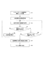
縮小可能性が「なし」に設定されると、パラメータ変更部62は変更パラメータを計算しない。図8は、カバレッジホール1が改善できないと判定された後に行われる処理の例を示すシーケンス図である。図8中に含まれている括弧書きの数字は、手順の番号を表す。   When the possibility of reduction is set to “none”, the parameter changing unit 62 does not calculate a changed parameter. FIG. 8 is a sequence diagram illustrating an example of processing performed after it is determined that the coverage hole 1 cannot be improved. The numbers in parentheses included in FIG. 8 represent procedure numbers.

(13)カバレッジホール1aについて縮小可能性が「なし」に設定されると、端末決定部71は、端末検索依頼を位置情報サーバ80に送信することにより、カバレッジホール1aからの距離が観測エリア閾値(L)以下である端末装置を問い合わせる。なお、この例では、端末決定部71とメッセージ生成部72は予め、観測エリア閾値(L)と注意喚起エリア閾値(X)を記憶しているものとする。   (13) When the possibility of reduction is set to “none” for the coverage hole 1a, the terminal determination unit 71 transmits a terminal search request to the position information server 80, so that the distance from the coverage hole 1a becomes the observation area threshold value. (L) Queries the following terminal devices. In this example, it is assumed that the terminal determination unit 71 and the message generation unit 72 store the observation area threshold (L) and the attention area threshold (X) in advance.

端末検索依頼のメッセージフォーマットの例を、図7の303に示す。端末検索依頼は、ヘッダ、メッセージタイプフィールド、ホール位置フィールド、観測エリア閾値フィールド、問合せ番号フィールドを備える。端末検索依頼では、メッセージタイプフィールド=2に設定されるものとする。端末決定部71は、ホール位置フィールドの値をカバレッジホール1aの位置情報とし、観測エリア閾値フィールドの値を観測エリア閾値(L)に設定する。さらに、周辺に位置する端末装置10を問い合わせるカバレッジホール1aを一意に認識できるように決定された問合せ番号を、問合せ番号フィールドに記録する。端末決定部71は、端末検索依頼を位置情報サーバ80に送信する。   An example of the message format of the terminal search request is shown in 303 of FIG. The terminal search request includes a header, a message type field, a hole position field, an observation area threshold field, and an inquiry number field. In the terminal search request, it is assumed that the message type field = 2 is set. The terminal determination unit 71 sets the value of the hole position field as the position information of the coverage hole 1a, and sets the value of the observation area threshold field to the observation area threshold (L). Further, the inquiry number determined so as to uniquely recognize the coverage hole 1a inquiring the terminal device 10 located in the vicinity is recorded in the inquiry number field. The terminal determination unit 71 transmits a terminal search request to the location information server 80.

(14)位置情報サーバ80の端末検索部85は、端末検索依頼に指定されているカバレッジホール1の位置からの距離が観測エリア閾値以下の端末装置10を検索する。端末検索部85は、端末装置10を検索するために、位置情報データベース84を参照するものとする。ここでは、MS1、MS2、MS3、MS4の4つの端末装置10がカバレッジホール1から観測エリア閾値(L)以下の距離に位置しているものとする。   (14) The terminal search unit 85 of the position information server 80 searches for the terminal device 10 whose distance from the position of the coverage hole 1 specified in the terminal search request is equal to or smaller than the observation area threshold. The terminal search unit 85 refers to the position information database 84 in order to search for the terminal device 10. Here, it is assumed that the four terminal devices 10, MS 1, MS 2, MS 3, and MS 4 are located at a distance equal to or smaller than the observation area threshold (L) from the coverage hole 1.

(15)端末検索部85は、得られた端末装置10を通知するために、検索結果メッセージをMDT管理サーバ50に送信する。検索結果メッセージのフォーマットの例を図7の304に示す。検索結果メッセージは、ヘッダ、メッセージタイプフィールド、該当数フィールド、端末IDフィールド、問合せ番号フィールドを備える。検索結果メッセージでは、メッセージタイプフィールド=3に設定されるものとする。端末検索部85は、問合せ番号フィールドの値を、手順(14)で受信した端末検索依頼の問合せ番号フィールドに格納されていた値に設定する。さらに、該当数フィールドにはカバレッジホール1aからL以内の距離に位置する端末装置10の数が記録され、端末IDフィールドには、カバレッジホール1aからL以内の距離に位置する端末装置10の各々を識別する識別子が記録される。ここでは、該当数フィールドに4が記録され、MS1、MS2、MS3、MS4の識別子が端末IDフィールドに記録されるものとする。   (15) The terminal search unit 85 transmits a search result message to the MDT management server 50 in order to notify the obtained terminal device 10. An example of the format of the search result message is shown at 304 in FIG. The search result message includes a header, a message type field, a corresponding number field, a terminal ID field, and an inquiry number field. In the search result message, the message type field = 3 is set. The terminal search unit 85 sets the value of the inquiry number field to the value stored in the inquiry number field of the terminal search request received in step (14). Further, the number of terminal devices 10 located within a distance L from the coverage hole 1a is recorded in the corresponding number field, and each of the terminal devices 10 located within a distance within L from the coverage hole 1a is recorded in the terminal ID field. An identifier for identification is recorded. Here, 4 is recorded in the corresponding number field, and the identifiers of MS1, MS2, MS3, and MS4 are recorded in the terminal ID field.

(16)端末決定部71は、位置情報サーバ80から送信されてきた検索結果メッセージに含まれている情報を抽出し、得られた端末装置のIDをメッセージ生成部72に出力する。このとき、端末決定部71は、問合せ番号に対応付けられたカバレッジホール1も、メッセージ生成部72に通知するものとする。   (16) The terminal determination unit 71 extracts information included in the search result message transmitted from the location information server 80, and outputs the obtained ID of the terminal device to the message generation unit 72. At this time, the terminal determination unit 71 also notifies the message generation unit 72 of the coverage hole 1 associated with the inquiry number.

(17)メッセージ生成部72は、端末決定部71から端末IDが入力されると、ホール通知を生成する。ホール通知の例を、図7の305に示す。ホール通知は、ヘッダ、メッセージタイプフィールド、MME識別子フィールド、基地局IDフィールド、端末IDフィールド、ホール位置フィールド、観測エリア閾値フィールド、注意喚起エリア閾値フィールドを備える。ホール通知では、メッセージタイプフィールド=4に設定されるものとする。メッセージ生成部72は、通知先の端末装置10が通信している基地局のIDを基地局IDフィールドに記録し、通知先の端末装置10の識別子を端末IDフィールドに記録する。ホール位置フィールドには、カバレッジホール1の位置が記録される。観測エリア閾値フィールドには、観測エリア閾値であるL(m)が記録され、注意喚起エリア閾値フィールドには注意喚起エリア閾値であるX(m)が記録される。   (17) When the terminal ID is input from the terminal determination unit 71, the message generation unit 72 generates a hole notification. An example of hole notification is shown at 305 in FIG. The hole notification includes a header, a message type field, an MME identifier field, a base station ID field, a terminal ID field, a hole position field, an observation area threshold field, and an attention area threshold field. In the hole notification, the message type field is set to 4. The message generation unit 72 records the ID of the base station with which the notification destination terminal device 10 is communicating in the base station ID field, and records the identifier of the notification destination terminal device 10 in the terminal ID field. In the hole position field, the position of the coverage hole 1 is recorded. In the observation area threshold field, L (m) that is the observation area threshold is recorded, and in the attention area threshold field, X (m) that is the attention area threshold is recorded.

MME識別子フィールドには、通知先の端末装置10が通信している基地局20が接続されているMME30の識別子が記録される。メッセージ生成部72は、通知先の端末装置10が通信している基地局20が接続されているMME30の識別情報を、EM40に問い合わせる。メッセージ生成部72は、EM40から通知された情報を、MME識別子フィールドに記録する。メッセージ生成部72は、ホール通知305を生成すると、宛先の端末装置MS1〜MS4に向けて送信する。   In the MME identifier field, an identifier of the MME 30 to which the base station 20 with which the terminal device 10 that is the notification destination is communicating is connected is recorded. The message generator 72 inquires of the EM 40 about the identification information of the MME 30 to which the base station 20 with which the terminal device 10 that is the notification destination is communicating is connected. The message generator 72 records the information notified from the EM 40 in the MME identifier field. When the message generation unit 72 generates the hole notification 305, the message generation unit 72 transmits the notification to the destination terminal devices MS1 to MS4.

(18)端末装置MS1〜MS4は、ホール通知305を受信する。ホール通知305を受信した端末の位置検出部17は、位置検出を行う頻度を高くする。例えば、位置検出部17は、リアルタイムに位置情報を取得できる。算出部15は、位置検出部17により現在の位置が検出されるたびに、ホール通知で通知されたカバレッジホール1からの距離を算出する。注意喚起部16は、算出部15で算出された距離がXm以下になると、ユーザに注意を促すための処理を行う。例えば、注意喚起部16は、ディスプレイ101に、カバレッジホール1に近づいていることを注意するための情報を表示する。図6に示す状態203の例では、MS1、MS3、MS4は、カバレッジホール1からの距離が注意喚起エリア閾値(X)以下である。従って、MS1、MS3、MS4では、ユーザへの注意喚起が行われる。   (18) The terminal devices MS1 to MS4 receive the hole notification 305. The position detection unit 17 of the terminal that has received the hole notification 305 increases the frequency of position detection. For example, the position detection unit 17 can acquire position information in real time. The calculation unit 15 calculates the distance from the coverage hole 1 notified by the hole notification every time the current position is detected by the position detection unit 17. When the distance calculated by the calculation unit 15 is equal to or less than Xm, the alerting unit 16 performs processing for prompting the user to pay attention. For example, the alerting unit 16 displays information for notifying that the user is approaching the coverage hole 1 on the display 101. In the example of the state 203 illustrated in FIG. 6, the distance from the coverage hole 1 of the MS1, MS3, and MS4 is equal to or less than the alert area threshold (X). Therefore, at MS1, MS3, and MS4, the user is alerted.

また、1つの端末装置10が複数のカバレッジホール1についてホール通知を受信することもあり得る。図9は、算出部15での計算結果と注意喚起を行うかの判定結果の例を示す。図9は、端末装置MS4での計算例であるものとし、端末装置MS4は、カバレッジホール1aとカバレッジホール1bの2つのカバレッジホール1についてのホール通知を受け取っているものとする。端末装置MS4の算出部15は、ホール通知に含まれているカバレッジホール1の位置を記憶する。ここでは、図9のNo.1はカバレッジホール1aのデータであり、No.2はカバレッジホール1bのデータであるものとする。端末装置MS4の現在の位置が北緯A、東経B、高さCであることが位置検出部17から算出部15に通知されると、算出部15は、すでに通知されているカバレッジホール1a、1bからの距離を算出する。距離の算出に用いる演算は、緯度、経度、高さが分かっている2点の間の距離を求めるための任意の演算方法とすることができる。ここでは、端末装置MS4の現在地からカバレッジホール1aまでの距離がD1であり、端末装置MS4の現在地からカバレッジホール1bまでの距離がD2であるものとする。ここで、観測エリア閾値L、注意喚起エリア閾値Xとの大小関係は、L>D2>X>D1であるものとする。すると、注意喚起部16は、D1はX以下であるので、端末装置MS4がカバレッジホール1aに接近していることを警告する画面をディスプレイ101に表示する。一方、カバレッジホール1bについては、端末装置MS4との間の距離は観測エリア閾値よりも近いが注意喚起エリア閾値よりも大きいため、警告は行わない。ただし、カバレッジホール1bと端末装置MS4の間の距離の観測は継続される。   In addition, one terminal apparatus 10 may receive a hole notification for a plurality of coverage holes 1. FIG. 9 shows an example of a calculation result in the calculation unit 15 and a determination result on whether to call attention. FIG. 9 is a calculation example in the terminal device MS4, and it is assumed that the terminal device MS4 has received hole notifications for the two coverage holes 1 of the coverage hole 1a and the coverage hole 1b. The calculation unit 15 of the terminal device MS4 stores the position of the coverage hole 1 included in the hole notification. Here, in FIG. 1 is data of the coverage hole 1a. 2 is data of the coverage hole 1b. When the position detection unit 17 notifies the calculation unit 15 that the current position of the terminal device MS4 is north latitude A, east longitude B, and height C, the calculation unit 15 reports the coverage holes 1a and 1b that have already been notified. The distance from is calculated. The calculation used for calculating the distance can be any calculation method for obtaining the distance between two points whose latitude, longitude, and height are known. Here, it is assumed that the distance from the current location of the terminal device MS4 to the coverage hole 1a is D1, and the distance from the current location of the terminal device MS4 to the coverage hole 1b is D2. Here, the magnitude relationship between the observation area threshold L and the attention area threshold X is assumed to be L> D2> X> D1. Then, since D1 is X or less, the alerting unit 16 displays a screen on the display 101 that warns that the terminal device MS4 is approaching the coverage hole 1a. On the other hand, for the coverage hole 1b, since the distance to the terminal device MS4 is closer than the observation area threshold but larger than the alert area threshold, no warning is given. However, the observation of the distance between the coverage hole 1b and the terminal device MS4 is continued.

図10は、ホール通知を受信した端末装置10の動作の例を説明するフローチャートである。図10は、手順(18)で行われる動作の例を示す。端末装置10がホール通知を受信することにより、算出部15は、カバレッジホール1の位置情報と、観測エリア閾値L、注意喚起エリア閾値Xを取得する(ステップS1)。位置検出部17は、位置情報の取得頻度を高くし、リアルタイムに位置情報を取得する(ステップS2、S3)。算出部15は、端末装置10とカバレッジホール1の間の距離を求め、注意喚起部16は、注意喚起エリア閾値Xと比較する(ステップS4)。端末装置10とカバレッジホール1の間の距離が注意喚起エリア閾値X以下である場合、注意喚起部16は、ユーザへの注意喚起をするために、ディスプレイ101に警告を表示する(ステップS4でYes、ステップS5)。その後、ステップS3以降の処理が繰り返される。   FIG. 10 is a flowchart illustrating an example of the operation of the terminal device 10 that has received the hole notification. FIG. 10 shows an example of the operation performed in the procedure (18). When the terminal device 10 receives the hole notification, the calculation unit 15 acquires the position information of the coverage hole 1, the observation area threshold L, and the attention area threshold X (step S1). The position detection unit 17 increases the acquisition frequency of position information and acquires position information in real time (steps S2 and S3). The calculation part 15 calculates | requires the distance between the terminal device 10 and the coverage hole 1, and the alerting part 16 compares with the alerting area threshold value X (step S4). When the distance between the terminal device 10 and the coverage hole 1 is equal to or less than the alert area threshold value X, the alert unit 16 displays a warning on the display 101 in order to alert the user (Yes in step S4). Step S5). Thereafter, the processing after step S3 is repeated.

一方、端末装置10とカバレッジホール1の間の距離が注意喚起エリア閾値Xよりも長い場合、注意喚起部16は、端末装置10とカバレッジホール1の間の距離を観測エリア閾値Lと比較する(ステップS4でNo、ステップS6)。端末装置10とカバレッジホール1の間の距離が観測エリア閾値L未満である場合、ステップS3以降の処理が繰り返される。(ステップS6でNo)。端末装置10とカバレッジホール1の間の距離が観測エリア閾値L以上である場合、カバレッジホール1に接近する可能性は低くなったため、カバレッジホール1までの距離の監視を終了する。そこで、位置検出部17は、位置情報の取得頻度を下げる(ステップS7)。さらに、算出部15は、端末装置10との間の距離が観測エリア閾値よりも長いカバレッジホール1に関するデータを消去する(ステップS8)。   On the other hand, when the distance between the terminal device 10 and the coverage hole 1 is longer than the attention area threshold value X, the attention drawing unit 16 compares the distance between the terminal device 10 and the coverage hole 1 with the observation area threshold value L ( No in step S4, step S6). When the distance between the terminal device 10 and the coverage hole 1 is less than the observation area threshold value L, the process after step S3 is repeated. (No in step S6). When the distance between the terminal device 10 and the coverage hole 1 is equal to or larger than the observation area threshold L, the possibility of approaching the coverage hole 1 is low, and thus the monitoring of the distance to the coverage hole 1 is terminated. Therefore, the position detection unit 17 decreases the frequency of acquiring position information (step S7). Furthermore, the calculation unit 15 deletes data related to the coverage hole 1 whose distance to the terminal device 10 is longer than the observation area threshold (step S8).

このように、改善できないと判定されたカバレッジホール1に端末装置10が近づいたときに、端末装置10のユーザに警告が出されるため、ユーザは、カバレッジホールを避けて通信しやすくなる。   As described above, when the terminal device 10 approaches the coverage hole 1 determined to be unable to be improved, a warning is issued to the user of the terminal device 10, so that the user can easily avoid the coverage hole and communicate.

<第2の実施形態>
第2の実施形態では、基地局90がカバレッジホール1の位置の通知対象となる端末装置10を特定する場合について説明する。
<Second Embodiment>
2nd Embodiment demonstrates the case where the base station 90 specifies the terminal device 10 used as the notification object of the position of the coverage hole 1. FIG.

〔装置構成〕
図11は、第2の実施形態で動作する装置の構成の例を説明する図である。端末装置10、MME30、EM40の構成や動作は、第1の実施形態と同様である。
〔Device configuration〕
FIG. 11 is a diagram illustrating an example of the configuration of an apparatus that operates in the second embodiment. The configurations and operations of the terminal device 10, the MME 30, and the EM 40 are the same as those in the first embodiment.

基地局90は、無線部23、パラメータ取得部24、チルト角調整部25、インタフェース28に加えて、ホール通知処理部91、端末決定部92、メッセージ生成部93、端末データベース94を備える。ホール通知処理部91は、改善できないカバレッジホール1の位置を通知するメッセージをMDT管理サーバ55から受信すると、カバレッジホール1の位置を抽出する。端末決定部92は、カバレッジホール1の情報を通知する対象となる端末を特定する。このとき、端末決定部92は、適宜、端末データベース94を参照することができる。端末データベース94は、基地局90と通信中の端末の識別子を記憶している。メッセージ生成部93は、端末決定部92で特定された端末に対して送信するメッセージを生成する。メッセージ生成部93で生成されるメッセージのフォーマットやメッセージの送信方法については後述する。無線部23、パラメータ取得部24、チルト角調整部25、インタフェース28の動作は、基地局20と同様である。   The base station 90 includes a hall notification processing unit 91, a terminal determination unit 92, a message generation unit 93, and a terminal database 94 in addition to the radio unit 23, parameter acquisition unit 24, tilt angle adjustment unit 25, and interface 28. When the hole notification processing unit 91 receives from the MDT management server 55 a message notifying the position of the coverage hole 1 that cannot be improved, the hole notification processing unit 91 extracts the position of the coverage hole 1. The terminal determination unit 92 specifies a terminal to be notified of information on the coverage hole 1. At this time, the terminal determination unit 92 can refer to the terminal database 94 as appropriate. The terminal database 94 stores an identifier of a terminal that is communicating with the base station 90. The message generation unit 93 generates a message to be transmitted to the terminal specified by the terminal determination unit 92. The format of the message generated by the message generation unit 93 and the message transmission method will be described later. The operations of the radio unit 23, parameter acquisition unit 24, tilt angle adjustment unit 25, and interface 28 are the same as those of the base station 20.

本実施形態では、MDT管理サーバ50の代わりにMDT管理サーバ55が用いられる。MDT管理サーバ55は、ホール通知部64を備え、さらに、インタフェース53、ホール情報データベース54、ホール制御部60を備える。ホール通知部64は、ホール判定部63によって、改善することができないと判定されたカバレッジホール1の位置を、基地局90に通知する。なお、ホール通知部64は、予め、観測エリア閾値と注意喚起エリア閾値を記憶しているものとする。インタフェース53、ホール情報データベース54、ホール制御部60の動作は、第1の実施形態と同様である。   In the present embodiment, an MDT management server 55 is used instead of the MDT management server 50. The MDT management server 55 includes a hall notification unit 64, and further includes an interface 53, a hall information database 54, and a hall control unit 60. The hole notification unit 64 notifies the base station 90 of the position of the coverage hole 1 determined by the hole determination unit 63 that cannot be improved. Note that the hole notification unit 64 stores an observation area threshold value and a warning area threshold value in advance. The operations of the interface 53, the hall information database 54, and the hall control unit 60 are the same as those in the first embodiment.

〔通信方法〕
図12は、第2の実施形態において、カバレッジホール1aを縮小できないと判定された後に行われる処理の例を示すシーケンス図である。図12中に含まれている括弧書きの数字は、手順の番号を表す。端末での通信の開始から、改善できないカバレッジホール1の検出までに行われる動作は、第1の実施形態で説明した手順(1)〜(12)と同様である。
〔Communication method〕
FIG. 12 is a sequence diagram illustrating an example of processing performed after it is determined that the coverage hole 1a cannot be reduced in the second embodiment. The numbers in parentheses included in FIG. 12 represent procedure numbers. The operations performed from the start of communication at the terminal to the detection of the coverage hole 1 that cannot be improved are the same as the procedures (1) to (12) described in the first embodiment.

(21)カバレッジホール1aについて縮小可能性が「なし」に設定されると、ホール通知部64は、基地局90に送信するためのホール通知306を生成する。ホール通知306のフォーマットの例を図13に示す。ホール通知306は、ヘッダ、メッセージタイプフィールド、基地局IDフィールド、ホール位置フィールド、観測エリア閾値フィールド、注意喚起エリア閾値フィールドを備える。ホール通知306では、メッセージタイプフィールド=5に設定されるものとする。ホール通知部64は、カバレッジホール1aを通信エリアに含む基地局の識別子、もしくは、通信エリアがカバレッジホール1aに隣接している基地局の識別子を、基地局IDフィールドに記録する。また、ヘッダには、基地局IDフィールドに識別子が記録された基地局のアドレスが設定される。ホール位置フィールド、観測エリア閾値フィールド、注意喚起エリア閾値フィールドに記録される値は、ホール通知305と同様である。以下の説明では、カバレッジホール1aの位置が基地局BS1に通知されたものとする。   (21) When the possibility of reduction for the coverage hole 1 a is set to “none”, the hole notification unit 64 generates a hole notification 306 for transmission to the base station 90. An example of the format of the hole notification 306 is shown in FIG. The hole notification 306 includes a header, a message type field, a base station ID field, a hole position field, an observation area threshold field, and a warning area threshold field. In the hole notification 306, it is assumed that the message type field = 5. The hole notification unit 64 records the identifier of the base station including the coverage hole 1a in the communication area or the identifier of the base station whose communication area is adjacent to the coverage hole 1a in the base station ID field. In the header, the address of the base station whose identifier is recorded in the base station ID field is set. The values recorded in the hole position field, the observation area threshold field, and the attention area threshold field are the same as those in the hole notification 305. In the following description, it is assumed that the position of the coverage hole 1a is notified to the base station BS1.

(22)基地局90のホール通知処理部91は、ホール通知305を受信すると、ホール位置フィールドの値に基づいてカバレッジホール1aの位置情報を取得する。ホール通知処理部91は、カバレッジホール1aの位置情報をメッセージ生成部93に出力する。端末決定部92は、端末データベース94を参照することにより、基地局90と通信中の端末装置を特定する。また、端末決定部92は、基地局90へハンドオーバ(HO)しようとしている端末装置10も特定する。さらに、端末決定部92は、基地局90の通信エリア内で新たに電源を投入されたなどの理由により基地局90への接続を行おうとしている端末装置10も特定する。端末決定部92は、特定した端末装置10の識別子を、その端末装置10の状態と対にしてメッセージ生成部93に出力する。   (22) Upon receiving the hole notification 305, the hole notification processing unit 91 of the base station 90 acquires the position information of the coverage hole 1a based on the value of the hole position field. The hole notification processing unit 91 outputs the position information of the coverage hole 1a to the message generation unit 93. The terminal determination unit 92 refers to the terminal database 94 to identify a terminal device that is communicating with the base station 90. The terminal determination unit 92 also identifies the terminal device 10 that is about to be handed over (HO) to the base station 90. Furthermore, the terminal determination unit 92 also identifies the terminal device 10 that is trying to connect to the base station 90 due to reasons such as the power being newly turned on within the communication area of the base station 90. The terminal determination unit 92 outputs the identified identifier of the terminal device 10 to the message generation unit 93 in a pair with the state of the terminal device 10.

(23)メッセージ生成部93は、端末決定部92から通知された端末装置10のうちで通信中の端末装置10に対し、ホール情報通知を送信する。ホール情報通知は、ヘッダの他、端末IDフィールド、ホール位置フィールド、観測エリア閾値フィールド、注意喚起エリア閾値フィールドを含む。端末IDフィールドには、宛先の端末装置10の識別子、ホール位置フィールドには、カバレッジホール1の位置が記録される。また、観測エリア閾値フィールドには観測エリア閾値L、注意喚起エリア閾値フィールドには注意喚起エリア閾値Xの情報が記録される。メッセージ生成部93は、無線送信部21を介して、生成したメッセージを宛先の端末装置10に送信する。   (23) The message generation unit 93 transmits a hole information notification to the terminal device 10 that is communicating among the terminal devices 10 notified from the terminal determination unit 92. The hall information notification includes a terminal ID field, a hall position field, an observation area threshold field, and an attention area threshold field in addition to the header. The identifier of the destination terminal device 10 is recorded in the terminal ID field, and the position of the coverage hole 1 is recorded in the hole position field. In addition, information of the observation area threshold L is recorded in the observation area threshold field, and information of the attention area threshold X is recorded in the attention area threshold field. The message generation unit 93 transmits the generated message to the destination terminal device 10 via the wireless transmission unit 21.

(24)メッセージ生成部93は、端末決定部92から通知された端末装置10のうちで、基地局90にハンドオーバしようとしている端末装置10に対して送信するメッセージ(ハンドオーバ応答メッセージ)を生成する。このハンドオーバ応答メッセージには、カバレッジホール1aの情報が含まれる。ハンドオーバ応答メッセージ307の例を図13に示す。ハンドオーバ応答メッセージは、基地局90と端末装置10の間のシグナリングにより送信される。ハンドオーバ応答メッセージには、ハンドオーバ応答フィールド、ハンドオーバ制御情報フィールド、ホール通知フィールドが含まれる。ハンドオーバ応答フィールドは、メッセージがハンドオーバ応答であることを示す情報が記録される。ハンドオーバ制御情報フィールドには、端末装置10がハンドオーバするために用いる情報が記録される。さらに、ホール通知フィールドには、端末ID、カバレッジホール1の位置、観測エリア閾値および注意喚起エリア閾値が記録される。ホール通知フィールドの例を図13の308に示す。なお、観測エリア閾値は観測エリアフィールドに記録され、注意喚起エリア閾値は注意喚起エリアフィールドに記録される。   (24) The message generation unit 93 generates a message (handover response message) to be transmitted to the terminal device 10 that is about to be handed over to the base station 90 among the terminal devices 10 notified from the terminal determination unit 92. This handover response message includes information on the coverage hole 1a. An example of the handover response message 307 is shown in FIG. The handover response message is transmitted by signaling between the base station 90 and the terminal device 10. The handover response message includes a handover response field, a handover control information field, and a hole notification field. In the handover response field, information indicating that the message is a handover response is recorded. Information used for the terminal device 10 to perform handover is recorded in the handover control information field. Furthermore, the terminal ID, the position of the coverage hole 1, the observation area threshold value, and the attention area threshold value are recorded in the hole notification field. An example of the hole notification field is shown at 308 in FIG. The observation area threshold is recorded in the observation area field, and the attention area threshold is recorded in the attention area field.

(25)メッセージ生成部93は、端末決定部92から通知された端末装置10のうちで、基地局90に接続しようとしている端末装置10に対して送信するメッセージ(初期接続応答メッセージ)を生成する。初期接続応答メッセージには、カバレッジホール1aの情報が含まれる。初期接続応答メッセージ309の例を図13に示す。初期接続応答メッセージも、基地局90と端末装置10の間のシグナリングにより送信される。初期接続応答メッセージには、初期接続応答フィールド、初期接続制御情報フィールド、ホール通知フィールドが含まれる。初期接続応答フィールドは、メッセージが初期接続応答であることを示す情報が記録される。初期接続制御情報フィールドには、端末装置10が基地局90に初期接続するために用いる情報が記録される。ホール通知フィールドは、ハンドオーバ応答のホール通知フィールド308と同様である。   (25) The message generation unit 93 generates a message (initial connection response message) to be transmitted to the terminal device 10 trying to connect to the base station 90 among the terminal devices 10 notified from the terminal determination unit 92. . The initial connection response message includes information on the coverage hole 1a. An example of the initial connection response message 309 is shown in FIG. The initial connection response message is also transmitted by signaling between the base station 90 and the terminal device 10. The initial connection response message includes an initial connection response field, an initial connection control information field, and a hole notification field. In the initial connection response field, information indicating that the message is an initial connection response is recorded. Information used for the terminal device 10 to make an initial connection to the base station 90 is recorded in the initial connection control information field. The hole notification field is the same as the hole notification field 308 of the handover response.

(26)基地局90の観測エリア中の端末装置10は、手順(23)〜(25)で送信されたメッセージのいずれかを受信する。カバレッジホール1aの位置が通知された端末装置10の位置検出部17は、位置検出を行う頻度を高くする。また、算出部15は、位置検出部17により現在の位置が検出されるたびに、ホール通知で通知されたカバレッジホール1からの距離を算出する。注意喚起部16は、算出部15で算出された距離がXm以下になると、ディスプレイ101に、カバレッジホール1に近づいていることを注意するための情報を表示する。   (26) The terminal device 10 in the observation area of the base station 90 receives any of the messages transmitted in the procedures (23) to (25). The position detection unit 17 of the terminal device 10 notified of the position of the coverage hole 1a increases the frequency of position detection. The calculation unit 15 calculates the distance from the coverage hole 1 notified by the hole notification every time the current position is detected by the position detection unit 17. When the distance calculated by the calculation unit 15 is equal to or less than Xm, the alerting unit 16 displays information for notifying that the user is approaching the coverage hole 1 on the display 101.

図14は、カバレッジホール1の位置を通知されたときの基地局90の処理の例を説明するフローチャートである。基地局90がMDT管理サーバ50からホール通知306を受信すると、ホール通知処理部91は、ホール通知306から、カバレッジホール1の位置情報、観測エリア閾値L、および、注意喚起エリア閾値Xを抽出する(ステップS11)。ホール通知処理部91は、抽出した情報を端末決定部92に出力する。端末決定部92は、基地局90と通信中の端末装置10を全て抽出し、メッセージ生成部93に通知する(ステップS12)。メッセージ生成部93は、抽出された全ての端末に、ホール通知を送信する(ステップS13)。   FIG. 14 is a flowchart for explaining an example of processing of the base station 90 when the position of the coverage hole 1 is notified. When the base station 90 receives the hole notification 306 from the MDT management server 50, the hole notification processing unit 91 extracts the position information of the coverage hole 1, the observation area threshold L, and the attention area threshold X from the hole notification 306. (Step S11). The hole notification processing unit 91 outputs the extracted information to the terminal determination unit 92. The terminal determination unit 92 extracts all the terminal devices 10 in communication with the base station 90 and notifies the message generation unit 93 (step S12). The message generator 93 transmits a hole notification to all the extracted terminals (step S13).

次に、端末決定部92は、ハンドオーバにより基地局90の通信エリアに入ってくる端末装置10があるかを確認する(ステップS14)。ハンドオーバにより基地局90の通信エリアに入ってくる端末装置10が特定できた場合、端末決定部92は、特定した端末装置10をメッセージ生成部93に通知する(ステップS14でYes)。メッセージ生成部93は、端末決定部92から通知された端末装置10に対して、ハンドオーバ応答メッセージ307(図13を参照)を送信する(ステップS15)。   Next, the terminal determination part 92 confirms whether there exists the terminal device 10 which enters into the communication area of the base station 90 by a handover (step S14). When the terminal device 10 entering the communication area of the base station 90 can be identified by the handover, the terminal determination unit 92 notifies the identified terminal device 10 to the message generation unit 93 (Yes in step S14). The message generation unit 93 transmits a handover response message 307 (see FIG. 13) to the terminal device 10 notified from the terminal determination unit 92 (step S15).

さらに、端末決定部92は、基地局90と新規の接続を開始しようとする端末装置10があるかを確認する(ステップS16)。基地局90と新規の接続を開始しようとする端末装置10が特定できた場合、端末決定部92は、特定した端末装置10をメッセージ生成部93に通知する(ステップS16でYes)。メッセージ生成部93は、端末決定部92から通知された端末装置10に対して、新規接続応答メッセージ309(図13を参照)を送信することにより、カバレッジホール1の情報を通知する(ステップS17)。その後、ステップS13以降の処理が繰り返される。   Furthermore, the terminal determination unit 92 checks whether there is a terminal device 10 that is about to start a new connection with the base station 90 (step S16). When the terminal device 10 that is about to start a new connection with the base station 90 can be identified, the terminal determination unit 92 notifies the identified terminal device 10 to the message generation unit 93 (Yes in step S16). The message generation unit 93 notifies the information on the coverage hole 1 by transmitting a new connection response message 309 (see FIG. 13) to the terminal device 10 notified from the terminal determination unit 92 (step S17). . Thereafter, the processing after step S13 is repeated.

なお、図14は処理の例であり、例えば、ステップS16とS17の処理がステップS14とS15の処理の前に行われるなど、実装に応じて処理の順序が変更される場合がある。   Note that FIG. 14 is an example of processing. For example, the processing order may be changed depending on the implementation, for example, the processing of steps S16 and S17 is performed before the processing of steps S14 and S15.

図15は、カバレッジホール1の位置を通知された端末装置10の動作の例を説明するフローチャートである。端末装置10の算出部15は、基地局90から受信した情報から、カバレッジホール1の位置情報と、観測エリア閾値L、注意喚起エリア閾値Xを取得する(ステップS21)。ステップS22〜S27の処理は、図10を参照しながら説明したステップS2〜S7と同様である。ステップS27において、位置検出部17が位置情報の取得頻度を下げた後、算出部15は、端末装置10と接続中の基地局90との間の通信が終了したかを確認する(ステップS28)。接続中の基地局90との間の通信が終了した場合、算出部15は、カバレッジホール1の位置情報、観測エリア閾値L、注意喚起エリア閾値Xを消去する(ステップS28でYes、ステップS29)。一方、接続中の基地局90との間の通信が終了していない場合、ステップS23以降の処理が繰り返される。(ステップS28でNo)。   FIG. 15 is a flowchart for explaining an example of the operation of the terminal apparatus 10 that is notified of the position of the coverage hole 1. The calculation unit 15 of the terminal device 10 acquires the position information of the coverage hole 1, the observation area threshold L, and the attention area threshold X from the information received from the base station 90 (step S21). The processes of steps S22 to S27 are the same as steps S2 to S7 described with reference to FIG. In step S27, after the position detection unit 17 decreases the frequency of acquiring the position information, the calculation unit 15 confirms whether communication between the terminal device 10 and the connected base station 90 is completed (step S28). . When communication with the connected base station 90 is completed, the calculation unit 15 deletes the position information of the coverage hole 1, the observation area threshold L, and the alert area threshold X (Yes in step S28, step S29). . On the other hand, when the communication with the connected base station 90 has not ended, the processes after step S23 are repeated. (No in step S28).

<第3の実施形態>
第3の実施形態では、カバレッジホール1の位置を通知する対象となる端末装置10が、MME30で特定される場合について説明する。
<Third Embodiment>
3rd Embodiment demonstrates the case where the terminal device 10 used as the object which notifies the position of the coverage hole 1 is specified by MME30.

〔装置構成〕
図16は、第3の実施形態で動作する装置の構成の例を説明する図である。基地局20、EM40の構成や動作は、第1の実施形態と同様である。端末装置10の構成は、第1の実施形態と同様であるが、第3の実施形態では、端末装置10は、位置情報をMME30に通知するものとする。本実施形態では、MDT管理サーバ55がネットワーク中に含まれている。
〔Device configuration〕
FIG. 16 is a diagram illustrating an example of the configuration of an apparatus that operates in the third embodiment. The configurations and operations of the base station 20 and the EM 40 are the same as those in the first embodiment. The configuration of the terminal device 10 is the same as that of the first embodiment, but in the third embodiment, the terminal device 10 notifies the MME 30 of position information. In this embodiment, the MDT management server 55 is included in the network.

MDT管理サーバ55の構成と動作は、第2の実施形態と同様である。ただし、ホール通知部64は、ホール判定部63によって、改善することができないと判定されたカバレッジホール1の位置を、MME30に通知するものとする。ホール通知311のメッセージフォーマットの例を図17に示す。MDT管理サーバ55のホール通知部64は、ホール通知311を生成する際に、カバレッジホール1を通信エリアに含む基地局20、もしくは、カバレッジホール1に通信エリアが隣接している基地局20を特定する。さらに、ホール通知部64は、特定した基地局20に接続されているMME30をEM40に問い合わせる。ホール通知部64は、EM40から通知されたMME30をホール通知311の宛先とし、その識別子をホール通知311のMME識別子フィールドに記録する。ホール位置フィールド、観測エリアフィールド、注意喚起エリアフィールドに記録される値は、ホール通知205と同様である。   The configuration and operation of the MDT management server 55 are the same as those in the second embodiment. However, the hole notification unit 64 notifies the MME 30 of the position of the coverage hole 1 determined by the hole determination unit 63 that cannot be improved. An example of the message format of the hole notification 311 is shown in FIG. When the hole notification unit 64 of the MDT management server 55 generates the hole notification 311, the base station 20 that includes the coverage hole 1 in the communication area or the base station 20 that is adjacent to the coverage hole 1 is specified. To do. Further, the hall notification unit 64 inquires of the EM 40 about the MME 30 connected to the identified base station 20. The hole notification unit 64 sets the MME 30 notified from the EM 40 as the destination of the hole notification 311 and records the identifier in the MME identifier field of the hole notification 311. The values recorded in the hole position field, observation area field, and attention area field are the same as those in the hole notification 205.

本実施形態で用いられるMME30は、インタフェース33、端末管理部34、端末情報データベース35、ホール通知処理部37、メッセージ生成部38を備える。インタフェース33は送信部31と受信部32を備え、基地局20、EM40、MDT管理サーバ55と通信する。端末管理部34は、エリア内端末管理部341、Tracking Area Update(TAU)処理部342、イニシャルアタッチ処理部343を有する。エリア内端末管理部341は、MME30が管理しているトラッキングエリア内に位置し、かつ、MME30との間の接続が確立されている端末装置10についての情報を処理する。TAU処理部342は、トラッキングエリアアップデート(TAU)に際して送受信されるメッセージの処理を行う。ここで、トラッキングエリアアップデートは、端末装置10が、MME30の管理対象であるトラッキングエリアに、他のトラッキングエリアから移動してくることを指す。イニシャルアタッチ処理部343は、イニシャルアタッチメントのために送受信されるメッセージを処理する。イニシャルアタッチメントは、MME30が管理しているトラッキングエリア内で、端末装置10に電源が投入された場合に、端末装置10がMME30に接続するための処理である。エリア内端末管理部341、TAU処理部342、イニシャルアタッチ処理部343は、いずれも、メッセージの送受信により端末装置10とMME30の接続関係が更新されると、端末情報データベース35を更新する。端末情報データベース35は、端末装置10の識別子と端末装置10の位置を対応付けて記憶する。   The MME 30 used in the present embodiment includes an interface 33, a terminal management unit 34, a terminal information database 35, a hole notification processing unit 37, and a message generation unit 38. The interface 33 includes a transmission unit 31 and a reception unit 32, and communicates with the base station 20, the EM 40, and the MDT management server 55. The terminal management unit 34 includes an in-area terminal management unit 341, a tracking area update (TAU) processing unit 342, and an initial attach processing unit 343. The in-area terminal management unit 341 processes information about the terminal device 10 that is located in the tracking area managed by the MME 30 and that has established a connection with the MME 30. The TAU processing unit 342 processes messages transmitted and received during tracking area update (TAU). Here, the tracking area update indicates that the terminal apparatus 10 moves from another tracking area to a tracking area that is a management target of the MME 30. The initial attachment processing unit 343 processes a message transmitted / received for the initial attachment. The initial attachment is a process for the terminal apparatus 10 to connect to the MME 30 when the terminal apparatus 10 is powered on within the tracking area managed by the MME 30. The in-area terminal management unit 341, the TAU processing unit 342, and the initial attach processing unit 343 all update the terminal information database 35 when the connection relationship between the terminal device 10 and the MME 30 is updated by message transmission / reception. The terminal information database 35 stores the identifier of the terminal device 10 and the position of the terminal device 10 in association with each other.

ホール通知処理部37は、MDT管理サーバ55から受信したホール通知311を処理することにより、カバレッジホール1の位置、観測エリア閾値、注意喚起エリア閾値を取得する。ホール通知処理部37は取得した情報をメッセージ生成部38に出力する。メッセージ生成部38は、端末情報データベース35を参照することにより、MME30に接続している端末装置10を特定する。さらに、メッセージ生成部38は、特定された端末装置10に送信するための通知メッセージ312を生成する。通知メッセージ312のフォーマットの例を図17に示す。通知メッセージ312のヘッダには、送信元アドレスとしてMME30のアドレスが設定され、宛先アドレスとして宛先の端末装置10のアドレスが設定される。さらに、ヘッダにはメッセージタイプフィールドが含まれており、通知メッセージ312に対応付けられた値(図17の例では6)が記録される。さらに。通知メッセージ312には、カバレッジホール1の位置、観測エリア閾値、注意喚起エリア閾値が含まれる。   The hole notification processing unit 37 processes the hole notification 311 received from the MDT management server 55, thereby acquiring the position of the coverage hole 1, the observation area threshold, and the attention area threshold. The hole notification processing unit 37 outputs the acquired information to the message generation unit 38. The message generator 38 specifies the terminal device 10 connected to the MME 30 by referring to the terminal information database 35. Further, the message generator 38 generates a notification message 312 for transmission to the identified terminal device 10. An example of the format of the notification message 312 is shown in FIG. In the header of the notification message 312, the address of the MME 30 is set as the transmission source address, and the address of the destination terminal device 10 is set as the destination address. Further, a message type field is included in the header, and a value (6 in the example of FIG. 17) associated with the notification message 312 is recorded. further. The notification message 312 includes the position of the coverage hole 1, the observation area threshold, and the attention area threshold.

なお、インタフェース33は、インタフェース123(図5)により実現される。また、CPU121は、HDD122に記録されているプログラムを読み込むことにより、端末管理部34、端末情報データベース35、ホール通知処理部37、メッセージ生成部38として動作する。   The interface 33 is realized by the interface 123 (FIG. 5). Further, the CPU 121 operates as a terminal management unit 34, a terminal information database 35, a hole notification processing unit 37, and a message generation unit 38 by reading a program recorded in the HDD 122.

〔通信方法〕
図18は、第3の実施形態において、カバレッジホール1aを縮小できないと判定された後に行われる処理の例を示すシーケンス図である。端末での通信の開始から、改善できないカバレッジホール1の検出までに行われる動作は、第1の実施形態で説明した手順(1)〜(12)と同様である。
〔Communication method〕
FIG. 18 is a sequence diagram illustrating an example of processing performed after it is determined that the coverage hole 1a cannot be reduced in the third embodiment. The operations performed from the start of communication at the terminal to the detection of the coverage hole 1 that cannot be improved are the same as the procedures (1) to (12) described in the first embodiment.

(31)カバレッジホール1aについて縮小可能性が「なし」に設定されると、ホール通知部64は、MME30に送信するためのホール通知311を生成する。   (31) When the possibility of reduction is set to “none” for the coverage hole 1a, the hole notification unit 64 generates a hole notification 311 to be transmitted to the MME 30.

(32)MME30のホール通知処理部37は、ホール通知311を受信すると、ホール位置フィールドの値から、カバレッジホール1aの位置情報を取得する。ホール通知処理部37は、カバレッジホール1aの位置情報をメッセージ生成部38に出力する。メッセージ生成部38は、端末情報データベース35を参照することにより、MME30に接続している端末装置10を特定する。さらに、メッセージ生成部38は、MME30へのトラッキングエリアアップデートをしようとしている端末装置10の情報をTAU処理部342に問い合わせる。また、メッセージ生成部38は、イニシャルアタッチメントを要求してきた端末装置10を、イニシャルアタッチ処理部343に問い合わせる。   (32) Upon receiving the hole notification 311, the hole notification processing unit 37 of the MME 30 acquires the position information of the coverage hole 1 a from the value of the hole position field. The hole notification processing unit 37 outputs the position information of the coverage hole 1a to the message generation unit 38. The message generator 38 specifies the terminal device 10 connected to the MME 30 by referring to the terminal information database 35. Further, the message generation unit 38 inquires of the TAU processing unit 342 about information of the terminal device 10 that is about to perform the tracking area update to the MME 30. In addition, the message generation unit 38 inquires of the initial attachment processing unit 343 about the terminal device 10 that has requested the initial attachment.

(33)メッセージ生成部38は、端末情報データベース35に記録されている端末装置10に対して、通知メッセージ312を送信する。さらに、メッセージ生成部38は、TAU処理部342およびイニシャルアタッチ処理部343から通知された端末装置10にも、通知メッセージ312を送信する。   (33) The message generation unit 38 transmits a notification message 312 to the terminal device 10 recorded in the terminal information database 35. Furthermore, the message generation unit 38 also transmits a notification message 312 to the terminal device 10 notified from the TAU processing unit 342 and the initial attach processing unit 343.

(34)通知メッセージ312を受信した端末装置10では、位置検出部17は、端末装置10の位置検出を行う頻度を高くする。算出部15は、位置検出部17から得られた情報に基づいて、通知メッセージ312に含まれているカバレッジホール1の位置から現在地までの距離を算出する。次に、注意喚起部16は、算出部15の計算結果を注意喚起エリア閾値Xと比較する。カバレッジホール1から現在地までの距離が注意喚起エリア閾値X以下の場合、注意喚起部16は、ディスプレイ101に、カバレッジホール1に近づいていることを知らせるための情報を表示する。カバレッジホール1から現在地までの距離が注意喚起エリア閾値Xより長い場合、注意喚起部16は、カバレッジホール1から現在地までの距離を観測エリア閾値Lと比較する。カバレッジホール1から現在地までの距離が観測エリア閾値Lより長い場合、位置検出部17は、位置情報を取得する頻度を低くする。なお、端末装置10は、通信を行っていない場合には、位置情報のリアルタイムでの取得や注意喚起を行わないようにすることもできる。この場合、通信を行っていない端末での処理負担が軽減される。   (34) In the terminal device 10 that has received the notification message 312, the position detection unit 17 increases the frequency of detecting the position of the terminal device 10. Based on the information obtained from the position detection unit 17, the calculation unit 15 calculates the distance from the position of the coverage hole 1 included in the notification message 312 to the current location. Next, the alerting unit 16 compares the calculation result of the calculating unit 15 with the alerting area threshold value X. When the distance from the coverage hole 1 to the current location is equal to or less than the alert area threshold X, the alert unit 16 displays information for notifying that the user is approaching the coverage hole 1 on the display 101. When the distance from the coverage hole 1 to the current location is longer than the attention calling area threshold value X, the attention drawing unit 16 compares the distance from the coverage hole 1 to the current location with the observation area threshold value L. When the distance from the coverage hole 1 to the current location is longer than the observation area threshold L, the position detection unit 17 decreases the frequency of acquiring the position information. Note that the terminal device 10 may be configured not to acquire position information in real time or alert when there is no communication. In this case, the processing burden on terminals that are not communicating is reduced.

図19は、カバレッジホール1の位置を通知されたときのMME30の処理の例を説明するフローチャートである。図19は、図18の手順(32)の処理の例を表している。なお、図19は処理の例であり、ステップS46とS47の処理がステップS44とS45の処理の前に行われるなど、実装に応じて処理の順序が変更される場合がある。   FIG. 19 is a flowchart for explaining an example of processing of the MME 30 when the position of the coverage hole 1 is notified. FIG. 19 shows an example of the process of the procedure (32) of FIG. Note that FIG. 19 is an example of processing, and the order of processing may be changed depending on the implementation, such as processing in steps S46 and S47 being performed before processing in steps S44 and S45.

MME30がMDT管理サーバ50からホール通知311を受信すると、ホール通知処理部37は、ホール通知311から、カバレッジホール1の位置情報、観測エリア閾値L、注意喚起エリア閾値Xを抽出する(ステップS41)。ホール通知処理部37は、抽出した情報をメッセージ生成部38に出力する。メッセージ生成部38は、MME30に接続中の端末装置10の情報を端末情報データベース35から取得し、得られた端末装置10に、通知メッセージ312を送信する(ステップS42、S43)。   When the MME 30 receives the hole notification 311 from the MDT management server 50, the hole notification processing unit 37 extracts the position information of the coverage hole 1, the observation area threshold L, and the attention area threshold X from the hole notification 311 (step S41). . The hole notification processing unit 37 outputs the extracted information to the message generation unit 38. The message generation unit 38 acquires information on the terminal device 10 currently connected to the MME 30 from the terminal information database 35, and transmits a notification message 312 to the obtained terminal device 10 (steps S42 and S43).

次に、メッセージ生成部38は、トラッキングエリアアップデートによりMME30の対応エリアに入ってくる端末装置10があるかを、TAU処理部342に確認する(ステップS44)。MME30の対応エリアに入ってくる端末装置10が特定できた場合、メッセージ生成部38は、特定した端末装置10に通知メッセージ312を送信することにより、カバレッジホール1の情報を通知する(ステップS44でYes、S45)。   Next, the message generation unit 38 checks with the TAU processing unit 342 whether there is a terminal device 10 that enters the corresponding area of the MME 30 by the tracking area update (step S44). When the terminal device 10 entering the corresponding area of the MME 30 can be identified, the message generator 38 notifies the information of the coverage hole 1 by transmitting a notification message 312 to the identified terminal device 10 (in step S44). Yes, S45).

さらに、メッセージ生成部38は、MME30と新規の接続を開始しようとする端末装置10があるかを、イニシャルアタッチ処理部343に確認する(ステップS46)。MME30と新規の接続を開始しようとする端末装置10が特定できた場合、メッセージ生成部38は、特定した端末装置10に通知メッセージ312を送信することにより、カバレッジホール1の情報を通知する(ステップS46でYes、ステップS47)。ステップS46でNoと判断された場合と、ステップS47の処理が終わった場合のいずれも、ステップS44以降の処理が繰り返される。   Furthermore, the message generation unit 38 confirms with the initial attach processing unit 343 whether there is a terminal device 10 that is about to start a new connection with the MME 30 (step S46). When the terminal device 10 that is about to start a new connection with the MME 30 can be identified, the message generation unit 38 notifies the information of the coverage hole 1 by transmitting a notification message 312 to the identified terminal device 10 (Step S1). Yes in S46, step S47). In both the case where it is determined No in step S46 and the case where the process in step S47 is completed, the processes after step S44 are repeated.

図20は、カバレッジホール1の位置を通知された端末装置10の動作の例を説明するフローチャートである。図20は、図18の手順(34)の処理の例を表している。端末装置10の算出部15は、MME30から受信した情報から、カバレッジホール1の位置情報、観測エリア閾値L、注意喚起エリア閾値Xを取得する(ステップS51)。端末装置10が通信していない場合、算出部15は、現在のMME30の対応エリアから他のMME30の対応エリアに移動するかを確認する(ステップS52でNo、ステップS53)。他のMME30の対応エリアに移動する場合、算出部15は、現在記憶しているカバレッジホール1に関する情報を削除する(ステップS53でYes、ステップS54)。他のMME30の対応エリアに移動しない場合、ステップS52以降の処理が繰り返される(ステップS53でNo)。   FIG. 20 is a flowchart illustrating an example of the operation of the terminal device 10 that is notified of the position of the coverage hole 1. FIG. 20 shows an example of the process of the procedure (34) of FIG. The calculation unit 15 of the terminal device 10 acquires the position information of the coverage hole 1, the observation area threshold L, and the attention area threshold X from the information received from the MME 30 (step S51). When the terminal device 10 is not communicating, the calculation unit 15 confirms whether or not the terminal device 10 moves from the corresponding area of the current MME 30 to the corresponding area of another MME 30 (No in step S52, step S53). When moving to the corresponding area of the other MME 30, the calculation unit 15 deletes the currently stored information regarding the coverage hole 1 (Yes in Step S53, Step S54). When the area does not move to the corresponding area of the other MME 30, the processes after step S52 are repeated (No in step S53).

一方、端末装置10が通信中である場合、位置検出部17は位置情報のリアルタイムでの取得を開始する(ステップS52でYes、ステップS55)。ステップS56〜S60の処理は、図10を参照しながら説明したステップS3〜S7と同様である。ステップS60において、位置検出部17が位置情報の取得頻度を下げた後、算出部15は、端末装置10で行われている通信が終了したかを確認する(ステップS61)。端末装置10の通信が終了した場合、ステップS52以降の処理が繰り返される(ステップS61でYes)。   On the other hand, when the terminal device 10 is communicating, the position detection unit 17 starts acquiring the position information in real time (Yes in step S52, step S55). The processing in steps S56 to S60 is the same as that in steps S3 to S7 described with reference to FIG. In step S60, after the position detection unit 17 decreases the acquisition frequency of the position information, the calculation unit 15 confirms whether the communication performed in the terminal device 10 has ended (step S61). When the communication of the terminal device 10 is completed, the processing after step S52 is repeated (Yes in step S61).

端末装置10での通信が終了していない場合、算出部15は、位置検出部17から得られた最新の位置情報を用いて、カバレッジホール1からの距離を再計算した上で、得られた値を観測エリア閾値Lと比較する(ステップS61でNo、ステップS62、S63)。端末装置10とカバレッジホール1の間の距離が観測エリア閾値L以内である場合、ステップS55以降の処理が繰り返される(ステップS63でYes)。端末装置10とカバレッジホール1の間の距離が観測エリア閾値Lより長い場合、算出部15は、現在のMME30の対応エリアから他のMME30の対応エリアに移動するかを確認する(ステップS63でNo、ステップS64)。他のMME30の対応エリアに移動する場合、算出部15は、現在記憶しているカバレッジホール1に関する情報を削除する(ステップS64でYes、ステップS65)。他のMME30の対応エリアに移動しない場合、ステップS61以降の処理が繰り返される(ステップS63でNo)。   When the communication with the terminal device 10 has not ended, the calculation unit 15 is obtained by recalculating the distance from the coverage hole 1 using the latest position information obtained from the position detection unit 17. The value is compared with the observation area threshold L (No in step S61, steps S62, S63). When the distance between the terminal device 10 and the coverage hole 1 is within the observation area threshold L, the processes after step S55 are repeated (Yes in step S63). When the distance between the terminal device 10 and the coverage hole 1 is longer than the observation area threshold L, the calculation unit 15 confirms whether the current area corresponding to the MME 30 moves to the area corresponding to another MME 30 (No in step S63). Step S64). When moving to the corresponding area of the other MME 30, the calculation unit 15 deletes the information related to the coverage hole 1 currently stored (Yes in Step S64, Step S65). When the area does not move to the corresponding area of the other MME 30, the processes after step S61 are repeated (No in step S63).

<第4の実施形態>
図21は、第4の実施形態にかかるシステムの例を示す。第4の実施形態では、改善することができないカバレッジホール1を検出すると、MDT管理サーバ55は、アプリケーションサーバ160にカバレッジホール1の位置の最新情報を通知する。アプリケーションサーバ160は、アプリケーションサーバ160が提供するアプリケーションをダウンロードしている端末装置10の各々について、識別子を記憶している。アプリケーションサーバ160は、カバレッジホール1の位置の情報が更新されるたびに、アプリケーションサーバ160が識別子を記憶している全ての端末装置10に、カバレッジホール1の位置を通知する。端末装置10は、通知されたカバレッジホール1のうち、その端末装置10が通信している基地局20に関連付けられているカバレッジホール1について、現在地との間の距離を測定する。カバレッジホール1との間の距離が注意喚起エリア閾値以下になると、端末装置10は、ユーザへの注意喚起を行うために、ディスプレイ101にメッセージを表示する。
<Fourth Embodiment>
FIG. 21 shows an example of a system according to the fourth embodiment. In the fourth embodiment, when the coverage hole 1 that cannot be improved is detected, the MDT management server 55 notifies the application server 160 of the latest information on the position of the coverage hole 1. The application server 160 stores an identifier for each terminal device 10 that is downloading an application provided by the application server 160. The application server 160 notifies the location of the coverage hole 1 to all the terminal devices 10 in which the application server 160 stores the identifier each time information on the location of the coverage hole 1 is updated. The terminal device 10 measures the distance between the current location and the coverage hole 1 associated with the base station 20 with which the terminal device 10 is communicating among the notified coverage holes 1. When the distance to the coverage hole 1 is equal to or less than the alert area threshold, the terminal device 10 displays a message on the display 101 in order to alert the user.

図22は、アプリケーションサーバ160の構成の例を示す。アプリケーションサーバ160は、インタフェース163、ホール通知処理部164、ダウンロード要求処理部165、メッセージ生成部166、および、端末情報データベース167を備える。インタフェース163は送信部161と受信部162を有しており、適宜、基地局20、MME30、EM40、MDT管理サーバ55との間の通信を行う。ホール通知処理部164は、MDT管理サーバ55から受信したホール通知を処理する。MDT管理サーバ55からアプリケーションサーバ160に送信されるホール通知のフォーマットは、図13に示したホール通知306と同様である。ホール通知処理部164は、ホール通知からカバレッジホール1の位置、観測エリア閾値(L)、注意喚起エリア閾値(X)、基地局20の識別子を取得して、記憶する。ここで、ホール通知には、通知されたカバレッジホール1を通信エリア含む基地局20、もしくは、カバレッジホール1が通信エリアに隣接している基地局20の識別子が記録されているものとする。   FIG. 22 shows an example of the configuration of the application server 160. The application server 160 includes an interface 163, a hole notification processing unit 164, a download request processing unit 165, a message generation unit 166, and a terminal information database 167. The interface 163 includes a transmission unit 161 and a reception unit 162, and performs communication with the base station 20, the MME 30, the EM 40, and the MDT management server 55 as appropriate. The hole notification processing unit 164 processes the hole notification received from the MDT management server 55. The format of the hole notification transmitted from the MDT management server 55 to the application server 160 is the same as the hole notification 306 shown in FIG. The hole notification processing unit 164 acquires the location of the coverage hole 1, the observation area threshold (L), the attention area threshold (X), and the identifier of the base station 20 from the hole notification and stores them. Here, it is assumed that the identifier of the base station 20 including the notified coverage hole 1 or the base station 20 adjacent to the communication area is recorded in the hole notification.

ダウンロード要求処理部165は、端末装置10からアプリケーションサーバ160に対して行われたダウンロードの要求を処理する。このとき、ダウンロード要求処理部165は、アプリケーションのダウンロードを許可する端末装置10に対して、その端末装置10を識別する識別子の通知を要求する。ダウンロード要求処理部165は、端末装置10から送信されてきたメッセージから端末装置10の識別子を取得し、端末情報データベース167に格納する。   The download request processing unit 165 processes a download request made from the terminal device 10 to the application server 160. At this time, the download request processing unit 165 requests the terminal device 10 that permits the download of the application to notify the identifier that identifies the terminal device 10. The download request processing unit 165 acquires the identifier of the terminal device 10 from the message transmitted from the terminal device 10 and stores it in the terminal information database 167.

メッセージ生成部166は、ホール通知処理部164に記憶されているカバレッジホール1の情報が更新されると、カバレッジホール1に関連付けてホール通知処理部164に記憶されている情報を、端末装置10に送信するためのメッセージを生成する。メッセージの送信先となる端末装置10は、端末情報データベース167に識別子が記録されている全ての端末装置10である。   When the information on the coverage hole 1 stored in the hole notification processing unit 164 is updated, the message generation unit 166 transmits the information stored in the hole notification processing unit 164 in association with the coverage hole 1 to the terminal device 10. Generate a message to send. The terminal device 10 that is the message transmission destination is all the terminal devices 10 whose identifiers are recorded in the terminal information database 167.

アプリケーションサーバ160は、EM40やMDT管理サーバ55などと同様に、CPU、HDD、インタフェースをハードウェアとして含む。インタフェースは、送信部161、受信部162として動作する。CPUは、プログラムをHDDから読み込むことにより、ホール通知処理部164、ダウンロード要求処理部165、メッセージ生成部166、端末情報データベース167として動作する。   The application server 160 includes a CPU, an HDD, and an interface as hardware, like the EM 40 and the MDT management server 55. The interface operates as a transmission unit 161 and a reception unit 162. The CPU operates as a hole notification processing unit 164, a download request processing unit 165, a message generation unit 166, and a terminal information database 167 by reading the program from the HDD.

図23は、第4の実施形態において、カバレッジホールを縮小できないと判定された後に行われる処理の例を示すシーケンス図である。端末装置10との通信の開始から、改善できないカバレッジホール1の検出までに行われる動作は、第1の実施形態で説明した手順(1)〜(12)と同様である。   FIG. 23 is a sequence diagram illustrating an example of processing performed after it is determined that the coverage hole cannot be reduced in the fourth embodiment. The operations performed from the start of communication with the terminal device 10 to the detection of the coverage hole 1 that cannot be improved are the same as the procedures (1) to (12) described in the first embodiment.

(41)カバレッジホール1aについて縮小可能性が「なし」に設定されると、ホール通知部64は、アプリケーションサーバ160にホール通知を送信する。   (41) When the possibility of reduction for the coverage hole 1a is set to “none”, the hole notification unit 64 transmits a hole notification to the application server 160.

(42)アプリケーションサーバ160のホール通知処理部164は、ホール通知を受信すると、カバレッジホール1の位置、観測エリア閾値(L)、注意喚起エリア閾値(X)、基地局20の識別子を取得する。さらに、ホール通知処理部164は、取得した情報を記憶する。メッセージ生成部166は、ホール通知処理部164に記憶されている全てのカバレッジホール1に関する情報を通知するメッセージを生成する。ここで生成される通知メッセージの宛先は、端末情報データベース167に識別子が記録されている個々の端末である。ここで生成される通知メッセージのフォーマットの例を図24に示す。   (42) When the hole notification processing unit 164 of the application server 160 receives the hole notification, the hole notification processing unit 164 acquires the position of the coverage hole 1, the observation area threshold (L), the attention area threshold (X), and the identifier of the base station 20. Further, the hole notification processing unit 164 stores the acquired information. The message generation unit 166 generates a message for notifying information on all the coverage holes 1 stored in the hole notification processing unit 164. The destination of the notification message generated here is an individual terminal whose identifier is recorded in the terminal information database 167. An example of the format of the notification message generated here is shown in FIG.

(43)メッセージ生成部166は、生成した通知メッセージを宛先の端末装置10に送信する。   (43) The message generation unit 166 transmits the generated notification message to the destination terminal device 10.

(44)通知メッセージを受信した端末装置10は、端末装置10の接続先の基地局20の識別子と同じ識別子に対応付けられているカバレッジホール1があるかを確認する。以下、端末装置10の接続先の基地局20の識別子と同じ識別子に対応付けられているカバレッジホール1を「処理対象のカバレッジホール1」と記載する。処理対象のカバレッジホール1が検出された場合、位置検出部17は、端末装置10の位置検出を行う頻度を高くする。算出部15は、位置検出部17から得られた情報に基づいて、処理対象のカバレッジホール1の位置から現在地までの距離を算出する。次に、注意喚起部16は、算出部15の計算結果を注意喚起エリア閾値Xと比較する。処理対象のカバレッジホール1から現在地までの距離が注意喚起エリア閾値X以下の場合、注意喚起部16は、ディスプレイ101に、カバレッジホール1に近づいていることを注意するための情報を表示する。処理対象のカバレッジホール1から現在地までの距離が注意喚起エリア閾値Xより長い場合、注意喚起部16は、カバレッジホール1から現在地までの距離を観測エリア閾値Lと比較する。処理対象のカバレッジホール1から現在地までの距離が観測エリア閾値Lより長い場合、位置検出部17は、位置情報を取得する頻度を低くする。   (44) The terminal device 10 that has received the notification message confirms whether there is a coverage hole 1 associated with the same identifier as the identifier of the base station 20 to which the terminal device 10 is connected. Hereinafter, coverage hole 1 associated with the same identifier as the identifier of base station 20 to which terminal apparatus 10 is connected is referred to as “coverage hole 1 to be processed”. When the processing target coverage hole 1 is detected, the position detection unit 17 increases the frequency of detecting the position of the terminal device 10. The calculation unit 15 calculates the distance from the position of the processing target coverage hole 1 to the current location based on the information obtained from the position detection unit 17. Next, the alerting unit 16 compares the calculation result of the calculating unit 15 with the alerting area threshold value X. When the distance from the coverage hole 1 to be processed to the current location is equal to or smaller than the attention area threshold value X, the attention drawing unit 16 displays information for notifying that the user is approaching the coverage hole 1 on the display 101. When the distance from the processing target coverage hole 1 to the current location is longer than the attention calling area threshold value X, the attention calling unit 16 compares the distance from the coverage hole 1 to the current location with the observation area threshold value L. When the distance from the coverage hole 1 to be processed to the current location is longer than the observation area threshold L, the position detection unit 17 decreases the frequency of acquiring the position information.

図25は、カバレッジホールの位置を通知された端末装置の動作の例を説明するフローチャートである。端末装置10は、通知メッセージを受信すると、端末装置10が位置する通信エリアを形成している基地局20の識別子を取得する(ステップS71、S72)。ステップS72で取得された識別子とカバレッジホール1に対応付けられた基地局20の識別子が一致する場合、位置検出部17はリアルタイムでの位置情報の取得を開始する(ステップS73でYes、ステップS74)。ステップS74〜S77の処理は、図10を参照しながら説明したステップS2〜S5と同様である。ステップS76でNoと判定された場合もしくはステップS77の処理が終わった場合、ステップS72以降の処理が繰り返される。一方、ステップS73において、処理対象のカバレッジホール1が発見されなかった場合、位置検出部17は、リアルタイムでの位置情報の取得を行わないように設定を変更する(ステップS73でNo、ステップS78)。   FIG. 25 is a flowchart for explaining an example of the operation of the terminal apparatus notified of the position of the coverage hole. When receiving the notification message, the terminal device 10 acquires the identifier of the base station 20 forming the communication area where the terminal device 10 is located (steps S71 and S72). If the identifier acquired in step S72 matches the identifier of the base station 20 associated with the coverage hole 1, the position detection unit 17 starts acquiring position information in real time (Yes in step S73, step S74). . The processes in steps S74 to S77 are the same as steps S2 to S5 described with reference to FIG. When it determines with No by step S76, or when the process of step S77 is complete | finished, the process after step S72 is repeated. On the other hand, when the processing target coverage hole 1 is not found in step S73, the position detection unit 17 changes the setting so as not to acquire position information in real time (No in step S73, step S78). .

<その他>
なお、実施形態は上記に限られるものではなく、様々に変形可能である。例えば、以上の説明で述べたフレームフォーマットは例であり、実装に応じて変更されることがある。また、データベースに含まれている情報要素も実装に応じて変更されうる。
<Others>
The embodiment is not limited to the above, and can be variously modified. For example, the frame format described in the above description is an example, and may be changed depending on the implementation. Also, the information elements included in the database can be changed according to the implementation.

さらに、観測エリア閾値L、中期喚起エリア閾値Xは、端末装置10、基地局90、MME30など個々の装置が予め記憶していてもよい。この場合、観測エリア閾値Lや中期喚起エリア閾値Xは、装置間で送受信されなくても良い。   Furthermore, the observation area threshold L and the mid-term awakening area threshold X may be stored in advance by individual devices such as the terminal device 10, the base station 90, and the MME 30. In this case, the observation area threshold value L and the mid-term awakening area threshold value X need not be transmitted and received between the devices.

RLF処理部61は、ある地点から一定の範囲に含まれる地点に対するRLF通知を受信した回数が予め記憶している所定の値を超えた場合に、カバレッジホール1を検出したと判定するように変形される場合もある。   The RLF processing unit 61 is modified to determine that the coverage hole 1 has been detected when the number of times the RLF notification is received for a point included in a certain range from a certain point exceeds a predetermined value stored in advance. Sometimes it is done.

また、LTE以外の通信方式が用いられるシステムにも、実施形態にかかる方法が適用されても良いものとする。   Further, the method according to the embodiment may be applied to a system using a communication method other than LTE.

1 カバレッジホール
10 端末装置
11、21 無線送信部
12、22 無線受信部
13、23 無線部
14 RLF生成部
15 算出部
16 注意喚起部
17 位置検出部
18 位置情報生成部
20、90 基地局
24 パラメータ取得部
25 チルト角調整部
26、31、41、51、81、161 送信部
27、32、42、52、82、162 受信部
28、33、43、53、83、163 インタフェース
30 MME
34 端末管理部
35、167 端末情報データベース
37、91、164 ホール通知処理部
38、72、93、166 メッセージ生成部
40 EM
44 パケット処理部
50、55 MDT管理サーバ
54 ホール情報データベース
60 ホール制御部
61 RLF処理部
62 パラメータ変更部
63 ホール判定部
64 ホール通知部
70 通知部
71、92 端末決定部
80 位置情報サーバ
84 位置情報データベース
85 端末検索部
86 位置情報更新部
94 端末データベース
101 ディスプレイ
102、113、121、131、141、151 CPU
103、122、132、142、152 HDD
104、114 メモリ
105、112 DSP
106、111 無線RF回路
115、123、133、143、153 インタフェース
160 アプリケーションサーバ
165 ダウンロード要求処理部
341 エリア内端末管理部
342 TAU処理部
343 イニシャルアタッチ処理部
DESCRIPTION OF SYMBOLS 1 Coverage hole 10 Terminal device 11, 21 Radio transmission part 12, 22 Radio reception part 13, 23 Radio part 14 RLF generation part 15 Calculation part 16 Attention part 17 Position detection part 18 Position information generation part 20, 90 Base station 24 Parameter Acquisition unit 25 Tilt angle adjustment unit 26, 31, 41, 51, 81, 161 Transmission unit 27, 32, 42, 52, 82, 162 Reception unit 28, 33, 43, 53, 83, 163 Interface 30 MME
34 Terminal management unit 35, 167 Terminal information database 37, 91, 164 Hall notification processing unit 38, 72, 93, 166 Message generation unit 40 EM
44 Packet processing unit 50, 55 MDT management server 54 Hall information database 60 Hall control unit 61 RLF processing unit 62 Parameter change unit 63 Hall determination unit 64 Hall notification unit 70 Notification unit 71, 92 Terminal determination unit 80 Location information server 84 Location information Database 85 Terminal search unit 86 Location information update unit 94 Terminal database 101 Display 102, 113, 121, 131, 141, 151 CPU
103, 122, 132, 142, 152 HDD
104, 114 Memory 105, 112 DSP
106, 111 Wireless RF circuit 115, 123, 133, 143, 153 Interface 160 Application server 165 Download request processing unit 341 In-area terminal management unit 342 TAU processing unit 343 Initial attach processing unit

Claims (11)

端末が基地局を介して通信する有線ネットワークに含まれる通信装置は、通信が可能な強度の電波を前記端末が受信できない領域であるカバレッジホールの位置を特定し、
前記カバレッジホールに近接する可能性がある端末であるホール近接端末を決定し、
前記ホール近接端末に、前記カバレッジホールの位置を特定可能な情報であるホール情報を通知する通知メッセージを送信する
処理を含むことを特徴とする通信方法。
A communication device included in a wired network in which a terminal communicates via a base station specifies a position of a coverage hole, which is an area where the terminal cannot receive radio waves having a strength capable of communication,
Determining a hall proximity terminal that is a terminal that may be close to the coverage hole;
A communication method comprising: transmitting a notification message notifying hole information, which is information capable of specifying a position of the coverage hole, to the hole proximity terminal.
前記基地局から受信する電波の強度が弱いことにより前記基地局との通信が切断された後に通信を再開した端末から、前記基地局との通信が切断された位置を通知する切断位置通知を受信し、
前記切断位置通知で特定される位置を前記カバレッジホールの位置とすると共に、前記カバレッジホールを縮小するために前記基地局で用いられるパラメータを制御するための制御メッセージを送信し、
前記基地局で前記パラメータの制御により前記カバレッジホールが縮小されない場合、前記ホール近接端末に前記通知メッセージを送信する
ことを特徴とする請求項1に記載の通信方法。
Received a disconnection position notification for notifying a position at which communication with the base station has been disconnected from a terminal that has resumed communication after communication with the base station has been disconnected due to a weak radio wave received from the base station. And
A position specified by the disconnection position notification is set as the position of the coverage hole, and a control message for controlling a parameter used in the base station to reduce the coverage hole is transmitted.
The communication method according to claim 1, wherein when the coverage hole is not reduced by the control of the parameter in the base station, the notification message is transmitted to the hole neighboring terminal.
前記通知メッセージは、前記カバレッジホールの位置と、注意喚起エリア閾値を含み、
前記ホール近接端末は、前記カバレッジホールの位置から前記ホール近接端末までの距離が前記注意喚起エリア閾値以下である場合、通信ができない領域の近傍に位置することに対する注意を前記ホール近接端末のユーザに喚起するための表示を、前記ホール近接端末に備えられたディスプレイに表示する
ことを特徴とする請求項1もしくは2に記載の通信方法。
The notification message includes the location of the coverage hole and a warning area threshold,
When the distance from the location of the coverage hole to the hall proximity terminal is equal to or less than the alert area threshold, the hall proximity terminal warns the user of the hall proximity terminal that it is located in an area where communication is not possible. The communication method according to claim 1, wherein a display for calling is displayed on a display provided in the hall proximity terminal.
前記有線ネットワークは、前記有線ネットワークと通信できる端末の位置を保持する位置情報サーバを含み、
前記通信装置は、前記位置情報サーバに、前記カバレッジホールからの距離を観測する対象となる観測エリアを決定するための観測エリア閾値を通知すると共に、前記カバレッジホールからの距離が前記観測エリア閾値以下の端末を前記位置情報サーバに問合せ、
前記通信装置は、前記位置情報サーバから通知された端末を、前記ホール近接端末とすることを特徴とする請求項1〜3のいずれかに記載の通信方法。
The wired network includes a location information server that holds a location of a terminal that can communicate with the wired network;
The communication device notifies the position information server of an observation area threshold value for determining an observation area to be observed from a distance from the coverage hole, and the distance from the coverage hole is equal to or less than the observation area threshold value. The location information server,
The communication method according to claim 1, wherein the communication apparatus uses the terminal notified from the location information server as the hall proximity terminal.
前記有線ネットワークは、端末の移動を管理する制御装置を含み、
前記通信装置は、前記制御装置の通信エリアに前記カバレッジホールがあると、前記制御装置に前記カバレッジホールの位置を通知し、
前記制御装置は、接続する基地局を介して前記通信エリアに位置する端末を前記ホール近接端末として、前記通知メッセージを送信する
ことを特徴とする請求項1〜3のいずれかに記載の方法。
The wired network includes a control device that manages the movement of a terminal;
When there is the coverage hole in the communication area of the control device, the communication device notifies the control device of the position of the coverage hole,
The method according to claim 1, wherein the control device transmits the notification message using a terminal located in the communication area as the hall proximity terminal via a base station to be connected.
前記有線ネットワークは、前記基地局を含み、
前記通信装置は、前記基地局の通信エリアに前記カバレッジホールがあると、前記基地局に前記カバレッジホールの位置を通知し、
前記基地局は、前記通信エリアに位置する端末を前記ホール近接端末として、前記通知メッセージを送信する
ことを特徴とする請求項1〜3のいずれかに記載の方法。
The wired network includes the base station,
When the communication device has the coverage hole in the communication area of the base station, the communication device notifies the base station of the position of the coverage hole,
The method according to any one of claims 1 to 3, wherein the base station transmits the notification message using a terminal located in the communication area as the hall proximity terminal.
前記通知メッセージは、前記カバレッジホールの位置と、前記注意喚起エリア閾値よりも大きな値である観測エリア閾値を含み、
前記ホール近接端末は、前記カバレッジホールの位置から前記ホール近接端末までの距離が前記観測エリア閾値を超えている場合、前記カバレッジホールの位置から前記ホール近接端末までの距離を求める頻度を低くする
ことを特徴とする請求項3に記載の通信方法。
The notification message includes a position of the coverage hole and an observation area threshold value that is larger than the attention area threshold value,
When the distance from the coverage hole position to the hole proximity terminal exceeds the observation area threshold, the hole proximity terminal decreases the frequency of obtaining the distance from the coverage hole position to the hole proximity terminal. The communication method according to claim 3 .
通信が可能な強度の電波を受信できない領域であるカバレッジホールの位置を表すホール情報と、注意喚起エリア閾値を通知する通知情報を受信する受信部と、
前記通知情報を受信すると、現在地から前記カバレッジホールの位置までの距離を算出する算出部と、
前記算出部で算出された距離が、前記注意喚起エリア閾値以下になると、通信ができない領域の近傍に位置することに対する注意をユーザに喚起するための処理を行う注意喚起部
を備えることを特徴とする通信端末。
A receiving unit that receives hole information indicating a position of a coverage hole, which is an area in which radio waves having a communication strength cannot be received, and notification information for notifying a warning area threshold;
When receiving the notification information, a calculation unit that calculates a distance from the current location to the position of the coverage hole;
Distance calculated by the calculating unit is equal to or below the alert area threshold, further comprising calling attention unit for performing processing to draw attention to the User chromatography The relative be located in the vicinity of the region where communication is not possible A characteristic communication terminal.
前記通知情報は、前記注意喚起エリア閾値よりも大きな値である観測エリア閾値をさらに含み、
前記算出部で算出された距離が前記観測エリア閾値を上回ると、前記算出部は、前記通知情報を前記受信部が再度受信するまで、前記通信端末の現在地から前記カバレッジホールまでの距離を計算する頻度を低くする
ことを特徴とする請求項8に記載の通信端末。
The notification information further includes an observation area threshold value that is larger than the attention area threshold value,
When the distance calculated by the calculation unit exceeds the observation area threshold, the calculation unit calculates the distance from the current location of the communication terminal to the coverage hole until the reception unit receives the notification information again. The communication terminal according to claim 8, wherein the frequency is reduced.
端末と無線通信すると共に、有線ネットワークを介して接続された通信装置とも通信する基地局装置であって、
通信が可能な強度の電波を前記端末が受信できない領域であるカバレッジホールの位置を特定する情報を、前記通信装置から受信する受信部と、
前記基地局装置に接続している端末、前記基地局装置に新規接続を要求する端末、および、前記基地局装置へハンドオーバしてくる端末を特定する特定部と、
前記カバレッジホールの位置を特定可能な情報であるホール情報を通知する通知メッセージを生成するメッセージ生成部と、
前記通知メッセージを、前記特定部で特定された端末に送信する送信部
を備えることを特徴とする基地局装置。
A base station device that communicates wirelessly with a terminal and also communicates with a communication device connected via a wired network,
A receiving unit that receives information identifying the position of a coverage hole, which is an area where the terminal cannot receive radio waves having a strength capable of communication, from the communication device;
A terminal that is connected to the base station device, a terminal that requests a new connection to the base station device , and a specifying unit that specifies a terminal that is handed over to the base station device ;
A message generator for generating a notification message for notifying hole information, which is information capable of specifying the position of the coverage hole;
A base station apparatus comprising: a transmission unit that transmits the notification message to a terminal identified by the identification unit.
前記メッセージ生成部は、
前記通知メッセージの送信先が、前記基地局装置へハンドオーバしてくる端末である場合は、ハンドオーバ要求に応答するシグナリングメッセージに前記カバレッジホールの位置を含め、
前記通知メッセージの送信先が、前記基地局装置への新規接続を要求する端末である場合は、接続要求に応答するシグナリングメッセージに前記カバレッジホールの位置を含める
ことを特徴とする請求項10に記載の基地局装置。
The message generator is
When the transmission destination of the notification message is a terminal that is handed over to the base station device, the location of the coverage hole is included in the signaling message responding to the handover request,
The location of the coverage hole is included in a signaling message responding to a connection request when the transmission destination of the notification message is a terminal requesting a new connection to the base station apparatus. Base station equipment.
JP2013555068A 2012-01-26 2012-01-26 COMMUNICATION METHOD, COMMUNICATION TERMINAL, AND BASE STATION DEVICE Expired - Fee Related JP5786966B2 (en)

Applications Claiming Priority (1)

Application Number Priority Date Filing Date Title
PCT/JP2012/051702 WO2013111309A1 (en) 2012-01-26 2012-01-26 Communication method, communication terminal and base station apparatus

Publications (2)

Publication Number Publication Date
JPWO2013111309A1 JPWO2013111309A1 (en) 2015-05-11
JP5786966B2 true JP5786966B2 (en) 2015-09-30

Family

ID=48873076

Family Applications (1)

Application Number Title Priority Date Filing Date
JP2013555068A Expired - Fee Related JP5786966B2 (en) 2012-01-26 2012-01-26 COMMUNICATION METHOD, COMMUNICATION TERMINAL, AND BASE STATION DEVICE

Country Status (4)

Country Link
US (1) US20140315577A1 (en)
EP (1) EP2809099A4 (en)
JP (1) JP5786966B2 (en)
WO (1) WO2013111309A1 (en)

Families Citing this family (10)

* Cited by examiner, † Cited by third party
Publication number Priority date Publication date Assignee Title
US8995255B2 (en) * 2012-08-03 2015-03-31 Intel Corporation Coverage adjustment in E-UTRA networks
EP2928242B1 (en) * 2013-01-04 2019-12-04 Huawei Technologies Co., Ltd. Positioning method, apparatus and system
US9401874B2 (en) * 2013-08-14 2016-07-26 Qualcomm Incorporated Minimizing coverage holes in a communication network
CN105530653B (en) * 2014-09-28 2019-04-12 国际商业机器公司 The method and apparatus for determining the covering cavity of the communication network of roadside
CN105704658B (en) * 2014-11-28 2020-10-27 中兴通讯股份有限公司 Terminal equipment and early warning method thereof
US9131346B1 (en) * 2015-01-16 2015-09-08 Elias B. Ware Telefinder
CN106507372A (en) * 2015-09-07 2017-03-15 中兴通讯股份有限公司 A kind of wireless network zone-skipping coverage detection method, device and communication system
EP3355599A1 (en) * 2017-01-31 2018-08-01 Gemalto M2M GmbH User equipment for searching a suitable base station
KR102554570B1 (en) 2018-09-21 2023-07-12 삼성전자 주식회사 Method and apparatus for determining an azimuth of a base station
CN114793374A (en) * 2022-04-11 2022-07-26 云南电网有限责任公司电力科学研究院 Blind zone wind driven generator communication system, method and medium

Family Cites Families (17)

* Cited by examiner, † Cited by third party
Publication number Priority date Publication date Assignee Title
US5920804A (en) * 1996-04-02 1999-07-06 Motorola, Inc. Method and apparatus for communications hand-off between multiple satellite systems
US6650896B1 (en) * 1998-08-13 2003-11-18 International Business Machines Corporation Error correlation for wireless networks
US6522888B1 (en) * 1999-08-31 2003-02-18 Lucent Technologies Inc. System for determining wireless coverage using location information for a wireless unit
US7076245B1 (en) * 2002-03-19 2006-07-11 Sprint Spectrum L.P. Proactive management of dropped calls in a wireless communication system
JP2004364223A (en) * 2003-06-09 2004-12-24 Nec Commun Syst Ltd Mobile communication system, advance notice server against leaving communication range and advance notice program against leaving communication range
US7293088B2 (en) * 2003-07-28 2007-11-06 Cisco Technology, Inc. Tag location, client location, and coverage hole location in a wireless network
US8190145B2 (en) * 2003-12-22 2012-05-29 Samsung Electronics Co., Ltd. Apparatus and method for mobile station-assisted optimization of a wireless network
US7969937B2 (en) * 2004-03-23 2011-06-28 Aruba Networks, Inc. System and method for centralized station management
US7236767B1 (en) * 2005-06-03 2007-06-26 Sprint Communications Company L.P. Wireless cell site finder and customer service system
US7821986B2 (en) * 2006-05-31 2010-10-26 Cisco Technology, Inc. WLAN infrastructure provided directions and roaming
JP5070989B2 (en) * 2007-08-21 2012-11-14 日本電気株式会社 Mobile communication terminal and out-of-service prediction method
US8565753B2 (en) 2007-11-09 2013-10-22 Nec Corporation Radio communication system, method and program
US9031571B2 (en) * 2008-04-11 2015-05-12 Alcatel Lucent Methods and apparatus for coverage verification in a wireless sensor network
JP2010130386A (en) * 2008-11-28 2010-06-10 Hitachi Ltd Radio communication system, radio base station, and non-sensible area notification method
US8762482B2 (en) * 2010-01-07 2014-06-24 Robert Bosch Gmbh Dead spot mitigation methods for media applications in vehicular environments
JP5790424B2 (en) * 2011-11-09 2015-10-07 富士通株式会社 Region detection apparatus, region detection method, and region detection program
US20130237231A1 (en) * 2012-03-09 2013-09-12 Qualcomm Incorporated Using access points to identify coverage holes

Also Published As

Publication number Publication date
EP2809099A4 (en) 2015-07-22
US20140315577A1 (en) 2014-10-23
JPWO2013111309A1 (en) 2015-05-11
EP2809099A1 (en) 2014-12-03
WO2013111309A1 (en) 2013-08-01

Similar Documents

Publication Publication Date Title
JP5786966B2 (en) COMMUNICATION METHOD, COMMUNICATION TERMINAL, AND BASE STATION DEVICE
EP3266231B1 (en) Selectively using beacon radio node location to determine user equipment location based on sensed movement of the beacon radio node
US8351900B2 (en) Man-in-the-middle detector and a method using it
KR101265509B1 (en) Providing location information
US8577360B2 (en) UE-based MDT measuring and reporting in a cellular radio access network
JP5316654B2 (en) Base station, mobile communication system, and broadcast information transmission method
KR101795679B1 (en) Access point initiated neighbor report request
US20090298505A1 (en) Profile Based Communications Service
US10123302B2 (en) Paging control apparatus, paging method, wireless terminal, and non-transitory computer-readable medium
JP2012080410A (en) Wireless communication system, wireless communication device and wireless communication method
KR20010041081A (en) Location beacon system
EP2822336A1 (en) Paging area control device, paging area control method, mobile communications system, and mobile station
JP2012256986A (en) Radio communication system, radio communication terminal and subscriber information management device
KR20170137617A (en) Method and apparatus for setup of wireless connection
JP6362557B2 (en) Mobile base station and location registration method
JP2003264494A (en) Method for generating radio wave condition
KR20190103383A (en) Communication method and communication device
TWI767144B (en) Threat detection apparatus and threat detection method therefor for wireless communication system
JP6760896B2 (en) Methods for detecting the position range of mobile phone terminals, mobile base stations and programs
US20220141679A1 (en) Event-based minimum drive test (mdt) log
JP5716545B2 (en) Communication control device, communication control method, radio base station, and mobile user terminal
CN111385817B (en) Neighbor cell reporting method and device, E-SMLC and terminal
CN106658702B (en) Positioning method and device
JP2006217095A (en) Mobile communication system, portable communication terminal, information server, method of notifying sensitivity degradation used therefor and program thereof
US20130184004A1 (en) Mobile communication method, positioning apparatus and radio base station

Legal Events

Date Code Title Description
A131 Notification of reasons for refusal

Free format text: JAPANESE INTERMEDIATE CODE: A131

Effective date: 20150512

A521 Request for written amendment filed

Free format text: JAPANESE INTERMEDIATE CODE: A523

Effective date: 20150608

TRDD Decision of grant or rejection written
A01 Written decision to grant a patent or to grant a registration (utility model)

Free format text: JAPANESE INTERMEDIATE CODE: A01

Effective date: 20150630

A61 First payment of annual fees (during grant procedure)

Free format text: JAPANESE INTERMEDIATE CODE: A61

Effective date: 20150713

R150 Certificate of patent or registration of utility model

Ref document number: 5786966

Country of ref document: JP

Free format text: JAPANESE INTERMEDIATE CODE: R150

LAPS Cancellation because of no payment of annual fees