JP5786877B2 - Air conditioner outdoor unit - Google Patents
Air conditioner outdoor unit Download PDFInfo
- Publication number
- JP5786877B2 JP5786877B2 JP2013021619A JP2013021619A JP5786877B2 JP 5786877 B2 JP5786877 B2 JP 5786877B2 JP 2013021619 A JP2013021619 A JP 2013021619A JP 2013021619 A JP2013021619 A JP 2013021619A JP 5786877 B2 JP5786877 B2 JP 5786877B2
- Authority
- JP
- Japan
- Prior art keywords
- outdoor unit
- electrical component
- heat exchanger
- outdoor
- main body
- Prior art date
- Legal status (The legal status is an assumption and is not a legal conclusion. Google has not performed a legal analysis and makes no representation as to the accuracy of the status listed.)
- Active
Links
Images


Description
本発明は、空気調和装置の室外機に関する。 The present invention relates to an outdoor unit for an air conditioner.
下記特許文献1には、室外機本体(ケーシング)の上部に設けられた送風ファンの駆動によって、室外機本体の側面から内部に取り入れた空気を上方へ吹き出す上吹き出しタイプの室外機が開示されている。この室外機には、略直方体形状の室外機本体の3つの側面に対向するように平面視コの字型に形成された熱交換器が設けられている。また、熱交換器の一の側端部と他の側端部との間に形成された開口部には、室外機本体の残りの1つの側面に対向するように制御ボックス(電装品ユニット)が配置されている。 The following Patent Document 1 discloses an up-out type outdoor unit that blows air taken in from the side of the outdoor unit body upward by driving a blower fan provided at the upper part of the outdoor unit body (casing). Yes. This outdoor unit is provided with a heat exchanger formed in a U-shape in plan view so as to face the three side surfaces of the substantially rectangular parallelepiped outdoor unit main body. In addition, a control box (electrical component unit) is provided in an opening formed between one side end and the other side end of the heat exchanger so as to face the remaining one side surface of the outdoor unit body. Is arranged.
この種の室外機においては、熱交換能力を維持したまま小型化することや、大型化することなく熱交換能力を増大することが望まれており、このために熱交換器を室外機本体の3つの側面だけでなく4つの側面に対向するように延長することが考えられている。
しかしながら、熱交換器の範囲を延長すると、当該熱交換器の一の側端部と他の側端部との間の開口部が小さくなり、当該開口部に占める制御ボックスの配置スペースの割合が大きくなる。当該開口部は、制御ボックスを配置するためだけでなく、室外機本体内に収容された機器のメンテナンスや交換を行うためにも利用されるため、当該開口部に占める制御ボックスの配置スペースの割合が大きくなると、メンテナンス等の作業性を確保することが困難となる。また、熱交換器の範囲を延長しない場合であっても、当該開口部に占める制御ボックスの配置スペースの割合を小さくすることは、メンテナンス等の作業性を高める上で有効である。
In this type of outdoor unit, it is desired to reduce the size while maintaining the heat exchange capability, and to increase the heat exchange capability without increasing the size. It is considered to extend not only three sides but also four sides.
However, when the range of the heat exchanger is extended, the opening between one side end of the heat exchanger and the other side end becomes smaller, and the ratio of the arrangement space of the control box to the opening is reduced. growing. Since the opening is used not only to arrange the control box but also to perform maintenance and replacement of the equipment accommodated in the outdoor unit body, the ratio of the control box arrangement space to the opening When becomes larger, it becomes difficult to ensure workability such as maintenance. Even if the range of the heat exchanger is not extended, reducing the proportion of the control box arrangement space in the opening is effective in improving workability such as maintenance.
本発明は、このような実情に鑑みてなされたものであり、熱交換器における一の側端部と他の側端部との間の開口部に占める電装品ユニットの配置スペースの割合を可及的に小さくし、室外機本体内の機器のメンテナンス等の作業性を確保することができる空気調和装置の室外機を提供することを目的とする。 The present invention has been made in view of such circumstances, and allows the proportion of the arrangement space of the electrical component units to occupy the opening between one side end and the other side end in the heat exchanger. An object of the present invention is to provide an outdoor unit of an air conditioner that can be made as small as possible and can secure workability such as maintenance of equipment in the outdoor unit body.
(1)本発明に係る空気調和装置の室外機は、
平面視で四角形状に形成され、前後の側面及び左右の側面からなる4つの側面を有する室外機本体と、
この室外機本体に収容され、前記室外機本体の1つの角部を除く範囲で前記4つの側面に対向して設けられた前後の熱交換部及び左右の熱交換部を有する熱交換器と、
前記室外機本体の上部に設けられ、当該室外機本体の側面から取り入れた空気を上方へ吹き出す送風ファンと、
この送風ファンの外周を囲い、空気の吹き出し口を形成する通風部材、及び前記通風部材の水平方向外側に配置されかつ前記室外機本体の平面形状に対応して平面視略四角形状に形成された外周部材を備えたベルマウスと、
前記室外機本体に収容され、前記熱交換器における一の側端部と他の側端部との間の開口部であって前記角部に配置される電装品ユニットと、を備えており、
前記電装品ユニットは、前記通風部材の下端を上下方向に跨いで設けられ、かつ前記通風部材の下端よりも上側に配置された部分が当該通風部材の水平方向の外側に配置されており、
前記外周部材における前記角部に対応する部分には、前記電装品ユニットを配置するための切り欠けが形成されており、
前記電装品ユニットは、前記切り欠けに配置されることによって、前記前熱交換部の外面と前記後熱交換部の外面との間の前記熱交換器の前後幅の範囲、及び、前記左熱交換部の外面と前記右熱交換部の外面との間の前記熱交換器の左右幅の範囲に入り込んでいることを特徴とする。
(1) An outdoor unit of an air conditioner according to the present invention is
An outdoor unit body which is formed in a quadrangular shape in plan view and has four side surfaces including front and rear side surfaces and left and right side surfaces ;
Housed in the outdoor unit main body, a heat exchanger having a heat exchange portion and the left and right of the heat exchange section before and provided opposite to the four sides in the range excluding the one corner of the outdoor unit main body,
A blower fan that is provided at the top of the outdoor unit main body and blows out air taken in from the side surface of the outdoor unit main body;
A ventilation member that surrounds the outer periphery of the blower fan and that forms an air outlet, and is disposed on the outer side in the horizontal direction of the ventilation member and formed in a substantially square shape in plan view corresponding to the planar shape of the outdoor unit body. A bell mouth with a peripheral member;
An electrical component unit that is housed in the outdoor unit main body, and is an opening between one side end and the other side end of the heat exchanger, and is disposed at the corner.
The electrical component unit is provided across the lower end of the ventilation member in the vertical direction, and the portion disposed above the lower end of the ventilation member is disposed outside the ventilation member in the horizontal direction,
In the portion corresponding to the corner portion in the outer peripheral member, a notch for arranging the electrical component unit is formed,
The electrical component unit is disposed in the notch, whereby the front-rear width range of the heat exchanger between the outer surface of the front heat exchange unit and the outer surface of the rear heat exchange unit, and the left heat It is characterized in that it enters the range of the left-right width of the heat exchanger between the outer surface of the exchange part and the outer surface of the right heat exchange part .
室外機本体の上部に送風ファンを備えた上吹き出しタイプの室外機において、送風ファンの外周を囲う通風部材の水平方向外側は空気の流れに寄与することが少なく、所謂デッドスペースとなっている場合が多い。そのため、本発明の室外機は、当該デッドスペースに電装品ユニットの一部を配置することによって、通風部材よりも下方における熱交換器の一の側端部と他の側端部との間の開口部に占める電装品ユニットの配置スペースの割合を小さくしている。これにより、室外機本体内の機器に対するメンテナンスや交換等の作業のために当該開口部を可及的に広く利用することができ、当該作業の作業性を向上させることができる。また、通風部材の下端よりも上側においては電装品ユニットの一部が空気の流れに影響を及ぼすことはほとんどなく、熱交換効率を悪化させることもない。
また、室外機本体の4つの側面に対向して熱交換器が配置されることによって、熱交換能力を維持しながら室外機をコンパクト化すること、又は、室外機を大型化することなく熱交換能力を増大することが可能となり、しかも、前述のように開口部に占める電装品ユニットの配置スペースの割合を小さくできるので、開口部を介して行うメンテナンス等の作業の作業性を損なうこともない。
また、室外機本体の上部に設けられる送風ファンは平面視で円形状の軌跡を描いて回転し、この送風ファンの外周を囲う通風部材は円筒形状を呈する。そのため、通風部材の水平方向外側であって平面視四角形状の室外機本体の角部には比較的広いデッドスペースが生じる。本発明においては、このような角部を利用することによって室外機本体の平面範囲内に電装品ユニットの一部の配置スペースを可及的に広く確保することができる。
In an up-out type outdoor unit that has a blower fan at the top of the outdoor unit body, the horizontal outside of the ventilation member that surrounds the outer periphery of the blower fan contributes less to the air flow and is a so-called dead space. There are many. Therefore, in the outdoor unit of the present invention, by disposing a part of the electrical component unit in the dead space, between the one side end portion and the other side end portion of the heat exchanger below the ventilation member. The ratio of the arrangement space of the electrical component unit in the opening is reduced. As a result, the opening can be used as widely as possible for work such as maintenance and replacement on the equipment in the outdoor unit body, and the workability of the work can be improved. In addition, a part of the electrical component unit hardly affects the air flow above the lower end of the ventilation member, and the heat exchange efficiency is not deteriorated.
In addition, the heat exchanger is arranged opposite to the four side surfaces of the outdoor unit main body, so that the outdoor unit can be made compact while maintaining the heat exchange capability, or heat exchange can be performed without increasing the size of the outdoor unit. It is possible to increase the capacity, and the ratio of the arrangement space of the electrical component unit occupying the opening can be reduced as described above, so that workability of maintenance work and the like performed through the opening is not impaired. .
In addition, the blower fan provided on the upper part of the outdoor unit main body rotates in a circular locus in plan view, and the ventilation member surrounding the outer periphery of the blower fan has a cylindrical shape. Therefore, a relatively wide dead space is generated at the corner of the outdoor unit main body that is in the horizontal direction outside the ventilation member and has a rectangular shape in plan view. In the present invention, by using such a corner portion, it is possible to secure as much as possible the arrangement space of a part of the electrical component unit within the plane range of the outdoor unit body.
(2)前記送風ファンは、前記室外機本体の平面範囲内において、当該室外機本体の他の角部側へ偏心して配置されていることが好ましい。
このような構成によって、通風部材の水平方向外側であって室外機本体の1の角部に電装品ユニットの配置スペースをより広く確保することができるとともに、熱交換器における空気の流通面積が大きい部分に送風ファンを寄せて配置することができ、熱交換効率を向上させることができる。
( 2 ) The blower fan is preferably arranged eccentrically toward the other corner of the outdoor unit main body within a plane range of the outdoor unit main body.
With such a configuration, it is possible to secure a wider arrangement space for the electrical component unit at the corner portion of the outdoor unit body on the outer side in the horizontal direction of the ventilation member, and the air circulation area in the heat exchanger is large. A ventilation fan can be arranged close to the part, and heat exchange efficiency can be improved.
(3)前記電装品ユニットと、前記熱交換器の一方の側端部との間には、前記圧縮機を出し入れ可能なスペースが形成されていることが好ましい。
このような構成によって、熱交換器の交換やメンテナンスを容易に行うことができる。
( 3 ) It is preferable that a space in which the compressor can be taken in and out is formed between the electrical component unit and one side end of the heat exchanger.
With such a configuration, the heat exchanger can be easily replaced and maintained.
(4)前記電装品ユニットは、前記室外機本体の1つの側面に対応して水平方向に配置された梁部材に支持されており、前記梁部材は、前記室外機本体の所定の取付箇所に前記電装品ユニットを取り付ける際に、当該電装品ユニットを前記取付箇所に案内するガイドレール部を有していることが好ましい。
このような構成によって、室外機本体における適正な取付箇所に電装品ユニットを迅速且つ簡単に位置付けることができる。
( 4 ) The electrical component unit is supported by a beam member disposed in a horizontal direction corresponding to one side surface of the outdoor unit main body, and the beam member is attached to a predetermined mounting location of the outdoor unit main body. When mounting the electrical component unit, it is preferable to have a guide rail portion for guiding the electrical component unit to the mounting location.
With such a configuration, the electrical component unit can be quickly and easily positioned at an appropriate mounting location in the outdoor unit body.
本発明によれば、熱交換器における一の側端部と他の側端部との間の開口部に占める電装品ユニットの配置スペースの割合を可及的に小さくし、室外機本体内の機器に対するメンテナンス等の作業のために開口部を広く使用することができ、当該作業の作業性を向上させることができる。 According to the present invention, the proportion of the arrangement space of the electrical component unit in the opening between one side end and the other side end in the heat exchanger is made as small as possible, The opening can be widely used for work such as maintenance on the equipment, and workability of the work can be improved.
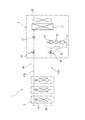
図1は、本発明の第1の実施の形態に係る室外機を有する空気調和装置の冷媒回路を示す模式図である。
空気調和装置1は、例えばビル用のマルチタイプの空気調和装置であり、1つ又は複数の室外機2に対して複数の室内機3が並列に接続され、冷媒が流通できるように、冷媒回路10が形成されている。
Drawing 1 is a mimetic diagram showing the refrigerant circuit of the air harmony device which has the outdoor unit concerning a 1st embodiment of the present invention.
The air conditioner 1 is a multi-type air conditioner for buildings, for example, and is a refrigerant circuit so that a plurality of
室外機2には、圧縮機11、四路切換弁12、室外熱交換器13、室外膨張弁14、送風ファン23、アキュムレータ20、オイルセパレータ21等が設けられ、これらは冷媒配管によって接続されている。また、室内機3には、室内膨張弁15および室内熱交換器16等が設けられている。四路切換弁12と室内熱交換器16とはガス側冷媒連絡配管17aにより接続され、室外膨張弁14と室内膨張弁15とは液側冷媒連絡配管17bにより接続されている。室外機2の内部冷媒回路の端末部には、ガス側閉鎖弁18と液側閉鎖弁19とが設けられている。ガス側閉鎖弁18は四路切換弁12側に配置されており、液側閉鎖弁19は室外膨張弁14側に配置されている。ガス側閉鎖弁18にはガス側冷媒連絡配管17aが接続され、液側閉鎖弁19には液側冷媒連絡配管17bが接続される。
The
上記構成の空気調和装置1において、冷房運転を行う場合には、四路切換弁12が図1において実線で示す状態に保持される。圧縮機11から吐出された高温高圧のガス状冷媒は、オイルセパレータ21及び四路切換弁12を経て室外熱交換器13に流入し、送風ファン23の作動により室外空気と熱交換して凝縮・液化する。液化した冷媒は、全開状態の室外膨張弁14を通過し、液側冷媒連絡配管17bを通って各室内機3に流入する。室内機3において、冷媒は、室内膨張弁15で所定の低圧に減圧され、さらに室内熱交換器16で室内空気と熱交換して蒸発する。そして、冷媒の蒸発によって冷却された室内空気は、図示しない室内ファンによって室内に吹き出され、当該室内を冷房する。また、室内熱交換器16で蒸発して気化した冷媒は、ガス側冷媒連絡配管17aを通って室外機2に戻り、四路切換弁12及びアキュムレータ20を経て圧縮機11に吸い込まれる。
In the air conditioner 1 having the above-described configuration, when the cooling operation is performed, the four-
他方、暖房運転を行う場合には、四路切換弁12が図1において破線で示す状態に保持される。圧縮機11から吐出された高温高圧のガス状冷媒は、オイルセパレータ21及び四路切換弁12を経て各室内機3の室内熱交換器16に流入し、室内空気と熱交換して凝縮・液化する。冷媒の凝縮によって加熱された室内空気は、室内ファンによって室内に吹き出され、当該室内を暖房する。室内熱交換器16において液化した冷媒は、全開状態の室内膨張弁15から液側冷媒連絡配管17bを通って室外機2に戻る。室外機2に戻った冷媒は、室外膨張弁14で所定の低圧に減圧され、さらに室外熱交換器13で室外空気と熱交換して蒸発する。そして、室外熱交換器13で蒸発して気化した冷媒は、四路切換弁12及びアキュムレータ20を経て圧縮機11に吸い込まれる。
On the other hand, when the heating operation is performed, the four-
図2は、室外機の外観を示す斜視図、図3は、室外機の側面パネル及び天板を取り外した状態を示す概略的な斜視図、図4は、室外機の側面パネル及び天板を取り外した状態を示す概略的な正面図である。また、図5は、天板を取り外した室外機の平面図、図6は、室外機の内部の平面図である。
本実施の形態の室外機2は、上吹き出しタイプであり、室外機本体(ケーシング)5と、この室外機本体5に内蔵された室外熱交換器13、圧縮機11、四路切換弁12、アキュムレータ20、オイルセパレータ21等の冷媒回路10(図1参照)を構成する機器と、電装品ユニット38と、室外機本体5の上部に設けられた送風ファン23等を備えている。
FIG. 2 is a perspective view showing the appearance of the outdoor unit, FIG. 3 is a schematic perspective view showing a state in which the side panel and the top plate of the outdoor unit are removed, and FIG. 4 is a side view of the outdoor unit and the top plate. It is a schematic front view which shows the state which removed. 5 is a plan view of the outdoor unit with the top plate removed, and FIG. 6 is a plan view of the interior of the outdoor unit.
The
そして、室外機2は、送風ファン23の駆動によって室外機本体5の側面から空気を吸い込み、室外熱交換器13との間で熱交換を行った後に室外機本体5の上部から上方へ空気を吹き出すように構成されている。
The
図2及び図3に示されるように、室外機本体5は、略直方体形状に形成されており、底フレーム26、支柱27、梁部材28a〜28d、下側面パネル29、上側面パネル25、天板24等を有している。底フレーム26は、平面視で四角形状に形成されている。また、底フレーム26の前後に対向する2辺には、地面に接地する脚部26aが設けられている。支柱27は、断面形状が略L字状で上下方向に長い長尺部材からなり、底フレーム26の4隅にボルト等によって取り付けられている。
As shown in FIGS. 2 and 3, the
図2に示されるように、天板24は、底フレーム26と略同一の平面視で四角形状に形成され、底フレーム26の上方に間隔をあけて配置されている。天板24の四隅には、各支柱27の上端がボルト等の連結具によって連結されている。天板24には、略四角形状の通風口24aが形成されており、この通風口24aには異物の侵入を防止するための網体24bが設けられている。
As shown in FIG. 2, the
図3及び図5に示されるように、梁部材28a〜28dは、支柱27の上部側であって、天板24から下方に所定の間隔をあけた位置に配置され、前後左右に隣接する支柱27の間に架設されている。そして、室外機本体5は、底フレーム26、天板24、支柱27、梁部材28a〜28d等からなる構造部材によって骨格が形成されている。
As shown in FIGS. 3 and 5, the
4本の梁部材28a〜28dには、ベルマウス30が取り付けられている。このベルマウス30は、送風ファン23の外周部を囲う通風ガイド(通風部材)30aを有しており、通風ガイド30aは、送風ファン23の円形状の回転軌跡に沿った円筒形状に形成され、室外機本体5からの空気の吹き出し口を形成している。また、前後の梁部材28a,28cには支持台31(図5参照)が架設されており、この支持台31に送風ファン23のモータ23a(図4参照)が取り付けられている。したがって、梁部材28a,28cは、送風ファン23を取り付けるための取付部材としても機能している。
A
図2に示されるように、梁部材28a〜28dと天板24との間に位置する室外機本体5の4つの側面には上側面パネル25が設けられている。送風ファン23、ベルマウス30、及び電装品ユニット38の上部は、上側面パネル25や天板24によって覆われることで、外部に露出しないように構成されている。
As shown in FIG. 2,
図5に示されるように、送風ファン23の回転中心Oは、室外機本体5の前後略中央部であってやや右側に偏心した位置に配置されている。また、図2に示されるように、天板24の通風口24aも、送風ファン23に合わせてやや右側に偏心した位置に配置されている。なお、天板24において、後述する電装品ユニット38の上方位置には通風口24aが形成されておらず、これにより通風口24aから浸入した雨水等が電装品ユニット38にかかってしまうのを防止している。
As shown in FIG. 5, the rotation center O of the
図6に示されるように、室外機本体5の底フレーム26の上面には、室外熱交換器13、圧縮機11、アキュムレータ20、オイルセパレータ21、四路切換弁12等の機器が搭載されている。室外熱交換器13は、クロスフィンコイル式であり、アルミニウム製の多数のフィンを伝熱管が水平に貫通し、伝熱管を流れる冷媒と室外熱交換器13を流通する空気との間で熱交換を行うように構成されている。
As shown in FIG. 6, devices such as an
室外熱交換器13は、室外機本体5の1つの角部(左前側の角部)5Aを除く範囲で4つの側面に対向(対応)し、かつ4つの側面に沿って略四角形状に屈曲されている。具体的に、室外熱交換器13は、室外機本体5の前側の側面(前面)に沿う前熱交換部32と、右側の側面に沿う右熱交換部33と、後側の側面(後面)に沿う後熱交換部34と、左側の側面に沿う左熱交換部35とを有している。そして、前熱交換部32と右熱交換部33との間、右熱交換部33と後熱交換部34との間、及び後熱交換部34と左熱交換部35との間が略90度に屈曲されている。なお、室外熱交換器13の各熱交換部32〜35は、室外機本体5の側面に対して必ずしも平行に対向していなくてもよく、傾斜した状態で対向していてもよい。また、本明細書において、室外機本体5の側面とは、外部に向いた実体的な側面、例えば、前述の上側面パネル25や後述する下側面パネル29、室外熱交換器13の外側面を覆う格子状の枠やパネルによって規定されるものであってもよいし、このような側面パネル25,29等を備えていない場合には、底フレーム26の4辺をそのまま上方に延長した仮想の面によって規定されてもよい。
The
図6に示されるように、前熱交換部32の左側端部(室外熱交換器13における一の側端部)32aと、左熱交換部35の前側端部(同他の側端部)35aとの間は、開口部36とされている。本実施の形態では、開口部36が、左前側に配置された支柱27によって2つに分けられており、以下の説明においては、室外機2の前面に配置された開口部36を前開口部36Aといい、左側面に配置された開口部36を左開口部36Bという。
As shown in FIG. 6, the left end portion (one side end portion in the outdoor heat exchanger 13) 32 a of the front
また、室外機本体5は、室外熱交換器13の一の側端部32aと支柱27との間、及びこの支柱27と室外熱交換器13の他の側端部35aとの間に、それぞれ下側面パネル29を着脱可能に備えており(図2参照)、この下側面パネル29によって前開口部36A及び左開口部36Bがそれぞれ閉鎖されている。なお、図示はしていないが、室外機本体5の側面における室外熱交換器13が配置された部分には、空気の流通が可能な格子状の枠やパネルが取り付けられていてもよい。
Moreover, the outdoor unit
図6に示されるように、閉鎖弁18,19は、室外機本体5の前開口部36Aに向くように取付台37を介して支持されている。また、圧縮機11は、前開口部36Aの右側寄りに配置され、前開口部36Aを介して前方から略全体を視認できる位置に配置される。また、底フレーム26上のアキュムレータ20やオイルセパレータ21は室外機本体5内の後部側に配置されている。
As shown in FIG. 6, the closing
図4に示されるように、後述する電装品ユニット38と室外熱交換器13の一の側端部32aとの間に形成された前開口部36Aの幅Wは、圧縮機11を通過可能な寸法に設定されており、圧縮機11の交換等のためにこのスペースを利用して圧縮機11を出し入れ可能である。
As shown in FIG. 4, the width W of the
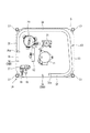
図4に示されるように、電装品ユニット38は、室外機2全体を制御するための制御基板41、圧縮機11や送風ファン23を駆動するための駆動基板(インバータ基板)42,43、リアクタ44(図7参照)、端子台45等の電気部品と、これら電気部品を収容する電装品箱50とを備えている。また、図3にも示されるように、電装品ユニット38は、室外機本体5における1つの角部5A、すなわち、室外熱交換器13が配置されていない室外機本体5の角部5Aに対応して配置されている。
As shown in FIG. 4, the
電装品箱50は、室外機本体5の略上端部から上下方向の中間部よりもやや下側までの範囲で設けられている。したがって、電装品箱50は、梁部材28a〜28dや室外熱交換器13の上端を上下方向に跨いで配置されている。また、電装品箱50は、ベルマウス30における円筒形状の通風ガイド30aの下端を上下方向に跨いで配置されている。
The
電装品ユニット38の電装品箱50は、角部5Aに配置された支柱27や、この支柱27に連結される梁部材28a,28b等にボルト等によって取り付けられ、支持されている。また、電装品箱50は、平面形状が互いに異なる上部51と、中間部52と、下部53とを備えており、これらの各部51,52,53は略同じ高さを有している。
The
電装品箱50の上部51は、梁部材28a,28bよりも上側に配置された部分である。図7は、図4のVII−VII矢視位置に相当する概略的な電装品箱の断面図である。電装品箱50の上部51は、その平面形状が略台形状に形成されている。具体的に、上部51は、室外機本体5の前面5aに略平行に沿った第1前面板51aと、第1前面板51aの後方に略平行に配置された第1背面板51bと、第1前面板51aと第1背面板51bの左端部を接続し、室外機本体5の左側面5bに略平行に沿った第1左側面板51cと、第1前面板51aと第1背面板51bの右端部を接続し、その後部側が左方向へ傾斜して配置された第1右側面板51dとを有している。以下、第1右側面板51dの後部側の傾斜部分を、右傾斜部51d1と呼称する。
The
電装品箱50の上部51には、第1前面板51aの後側に近接して制御基板(操作基板)41が配置され、第1背面板51bの前側に近接してリアクタ44が配置されている。また、第1前面板51aには、操作窓51a1が形成されている。制御基板41には、室外ユニットの各種設定や試運転等を行うためのスイッチ等の操作部や、異常時に点灯するLED等が設けられており、この操作窓51a1から制御基板41上の操作部を操作したりLED等を確認したりすることが可能となっている。そして、電装品箱50の上部51に制御基板41を配置することで操作窓51a1を介して操作部の操作やLED等の確認を立った姿勢で容易に行うことが可能である。なお、操作窓51a1は、開閉可能な蓋板51a2によって閉鎖されている。また、第1背面板51bには、電装品箱50内に空気を取り入れるための第1取入口56が形成されている。リアクタ44は、高発熱部品であり、主として第1取入口56から取り入れられた空気によって冷却される。
In the
図5に示されるように、電装品箱50の上部51は、ベルマウス30と隣接して配置されている。ベルマウス30は、通風ガイド30aと、この通風ガイド30aの水平方向外側に配置されて梁部材28a〜28dに支持される外周部材30bとからなっている。通風ガイド30aは送風ファン23の全周を囲うように円筒形状に形成されているが、外周部材30bは、平面視略四角形状で、電装品箱50の配置箇所に切欠30cが形成されている。
As shown in FIG. 5, the
図4に示されるように、電装品箱50の中間部52は、梁部材28a,28bよりも下側に配置されている。図8は、図4におけるVIII−VIII矢視位置に相当する電装品箱の概略的な断面図である。中間部52は、平面視で略四角形状に形成されている。具体的に、中間部52は、室外機本体5の前面5aに略平行に沿った第2前面板52aと、第2前面板52aの後方に配置されるとともに、右側の一部が前方に傾斜して配置された第2背面板52bと、第2前面板52aと第2背面板52bの左端部を接続し、室外機本体5の左側面5bに略平行に沿った第2左側面板52cと、第2前面板52aと第2背面板52bの右端部を接続する第2右側面板52dとを有している。
なお、以下においては第2背面板52bにおける右側の傾斜部分を、後傾斜部52b1という。
As shown in FIG. 4, the
Hereinafter, the right inclined portion of the
第2前面板52aは、第1前面板51a(図7参照)と同一の板材からなり、第1前面板51aの下方に一体的に連なっている。また、第2左側面板52cは、第1左側面板51cと同一の板材からなり、第1左側面板51cの下方に一体的に連なっている。また、第2左側面板52cは、その一部が左方向に若干膨出しており、この膨出部分には電装品箱50内の空気を排出するための排出口57が形成されている。この電装品箱50の中間部52には、第2前面板52aの後側に近接して端子台45が配置され、第2背面板52bの前側に送風ファン23用の駆動基板43が配置されている。特に、駆動基板43には、スイッチング素子を含むファンドライバ43aが設けられ、このファンドライバ43aは、第2背面板52bの後傾斜部52b1から外部へ突出するヒートシンク43bを介して空冷されている。
The second
図4に示されるように、電装品箱50の下部53は、中間部52の下方に設けられている。図9は、図4におけるIV−IV矢視位置に相当する電装品箱の概略的な断面図である。下部53は、上述の第2背面板52bと第2右側面板52dをそのまま下方に延長することによって構成された第3背面板53b及び第3右側面板53dを有している。また、電装品箱50の下部53は、その右側の一部が室外機本体5の前面5aに略沿って配置されるとともに、左側の一部が後方へ傾斜する第3前面板53aを有している。以下においては、第3前面板53aにおける傾斜部分を前傾斜部53a1と呼称する。この前傾斜部53a1は、図7に示す右傾斜部51d1と略平行に配置されている。
As shown in FIG. 4, the
電装品箱50の下部53の内部には、第3前面板53aにおける前傾斜部53a1の後側に近接して圧縮機11の駆動基板42が配置されている。また、前傾斜部53a1の表面には冷却ジャケット48が設けられ、この冷却ジャケット48には、冷媒回路10(図1参照)の冷媒配管から引き回された冷却用冷媒配管47が接している。圧縮機11の駆動基板42には高発熱部品であるIGBT等のパワー素子(スイッチング素子)を有するパワーモジュールが実装されており、このパワーモジュールが冷却用冷媒配管47を流れる冷媒によって冷却されている。また、電装品箱50の下部53の底壁には、電装品箱50内に空気を取り入れるための第2取入口58が形成されている。
Inside the
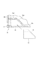
図10は、電装品箱を後斜め上方から見た斜視図である。電装品箱50の後部側における上部51と中間部52との境界には、第1右側面板51dの右傾斜部51d1及び第1背面板51bと略平行に形成された凹状の嵌合溝60が形成されている。一方、図11に示されるように、室外機本体5の前部に配置された梁部材28aの左端部は後方へ凹んでいる。具体的には、梁部材28aの左端部には、嵌合溝60の形状に倣って後方へ傾斜する傾斜部28a1と、この傾斜部28a1の左端部から室外機本体5の前面5aと略平行に延びる平行部28a2とが形成されている。
FIG. 10 is a perspective view of the electrical component box as viewed from the rear and obliquely above. A concave
そして、電装品箱50を室外機本体5に取り付けるときに、梁部材28aの傾斜部28a1を嵌合溝60に嵌合させつつ矢印で示す左斜め後方に挿入することで、当該傾斜部28a1が電装品箱50を所定の取付箇所へ案内するガイドレールとして機能する。このような傾斜部(ガイドレール部)28a1を設けることで電装品箱50を適切な箇所に簡単且つ迅速に位置づけることができる。
And when attaching the
また、梁部材28aに傾斜部(ガイドレール部)28a1を設けることで、冷却用冷媒配管47(図9参照)に干渉することなく電装品箱50を取り付けることができる。電装品箱50を室外機本体5に取り付ける際、冷却用冷媒配管47を含めた冷媒配管は既に室外機本体5に組み付けられているので、電装品箱50は、冷却用冷媒配管47に干渉しないように取り付ける必要がある。本実施の形態では、電装品箱50の下部53における前傾斜部53a1に冷却用冷媒配管47が設けられているため、電装品箱50を室外機本体5の正面からそのまま後方へ向けて取り付けることができない。そのため、この冷却用冷媒配管47が装着された前傾斜部53a1と略平行なガイドレール部28a1を梁部材28aに形成し、このガイドレール部28a1に沿って電装品箱50を取り付けることで、当該電装品箱50が冷却用冷媒配管47に干渉してしまうのを防止している。
Further, by providing the
また、冷却用冷媒配管47は、平面視において電装品箱50の平面範囲内に配置されている。すなわち、電装品箱50の下部53は、第3前面板53aの前傾斜部53a1が第1,第2前面板51a,52aよりも後退しており、これによって電装品箱50にはその底壁を上方に凹ました形態の凹部(配置凹部)54が形成されている。そして、冷却用冷媒配管47は、凹部54内に配置されることによって電装品箱50の平面範囲内に配置されている。そのため、冷却用冷媒配管47が電装品箱50から側方へ突出することがなく、冷却用冷媒配管47を含めた電装品箱50の平面的な配置スペースを可及的に小さくすることが可能となっている。
Further, the cooling
また、図4に示されるように、電装品箱50内の電気配線62は、凹部54内における電装品箱50の底壁(中間部52の底壁)54aから下方へ引き出されている。したがって、圧縮機11の駆動基板42が収容された電装品箱50の下部53を通すことなく電気配線62を外部へ引き出すことができ、駆動基板42から発生するノイズが電気配線62に与える影響を小さくすることができる。
As shown in FIG. 4, the
図12は、電装品箱における空気の流れを示す説明図である。
送風ファン23を作動させると、外気は室外機本体5の側面から吸い込まれ、室外熱交換器13との間で熱交換を行った後、上方へ吹き出される。このとき、室外機本体5の内部は、送風ファン23の作動によって負圧となり、特に、図12に示すB部は、A部よりも送風ファン23に近いため圧力がより低くなる。また、室外機本体5の外部やベルマウス30における通風ガイド30aの外側であるC部は正圧又は大気圧となる。
FIG. 12 is an explanatory view showing the flow of air in the electrical component box.
When the
前述したように、電装品箱50の上部51の側面には第1取入口56が形成され、下部53の底面には第2取入口58が形成され、中間部52の側面には排出口57が形成されている。上記のようなC部とB部との差圧によって、第1取入口56から電装品箱50に空気が取り入れられるとともに排出口57から排出され、この空気の流れによって電装品箱50の上部側の機器が冷却される。また、A部とB部との差圧によって、第2取入口から電装品箱50に空気が取り入れられるとともに排出口57から排出され、この空気の流れによって電装品箱50の下部側の機器が冷却される。
As described above, the
ここで、A部とBとの差圧は、C部とB部との差圧よりも小さいため、第1取入口56から排出口57への空気の流れよりも第2取入口58から排出口57への空気の流れが弱くなる。しかしながら、第1取入口56から排出口57への比較的強い空気の流れによって、第1取入口56から排出口57への空気の流れが誘引され、第2取入口58からの空気の流入が促進される。このような作用によって電装品箱50の放熱性をより高めることが可能となっている。
Here, since the differential pressure between the A part and the B part is smaller than the differential pressure between the C part and the B part, the air is discharged from the
上記実施の形態において、室外熱交換器13は、室外機本体5の4つの側面に対向して配置されている(図6参照)。したがって、当該室外機本体5の3つの側面に対向して室外熱交換器13が配置される場合に比べて、空気の流通面積を拡大することができ、熱交換の能力を高めることができる。また、言い換えると、室外機本体の4つの側面に対向するように室外熱交換器13を配置することによって、室外機本体5のサイズを小さくしたとしても空気の流通面積を維持することができる。そのため、室外熱交換器13の能力を低下させることなく、室外機本体4の小型化を図ることができる。
In the said embodiment, the
その反面、室外熱交換器13が室外機本体5の4つの側面に配置されていると、室外熱交換器13における一の側端部32aと他の側端部35aとの間に形成される開口部36が小さくなり、この開口部36に占める電装品箱50の配置スペースの割合が相対的に大きくなる。そのため、開口部36の残りのスペースを利用して室外機本体5内の機器のメンテナンスや交換等の作業を行う場合に作業性が悪化する可能性がある。
On the other hand, when the
この点に関して、本実施の形態の室外機2は、電装品箱50が通風ガイド30aの下端(図12において符号Hで示す)を上下方向に跨いで配置されているので、電装品箱50の全体を通風ガイド30aの下端Hよりも下方に配置する場合に比べて、開口部36に占める電装品箱50の配置スペースを小さくすることができる。そのため、電装品箱50の配置スペースを除く残りの開口部36のスペースを可及的に広く確保することができ、当該開口部36を利用して室外機本体5内の機器に対するメンテナンス等の作業を行い易くすることができる。
In this regard, in the
また、通風ガイド30aの下端Hよりも上方であって通風ガイド30aの水平方向の外側の領域は、室外機本体5内における空気の流れにほとんど寄与しておらず、この領域に電装品箱50の一部を配置したとしても、室外機本体5内の空気の流れに悪影響を及ぼすことはほとんどなく、熱交換効率を悪化させることもない。
Further, the region above the lower end H of the
図3及び図4に示されるように、電装品ユニット38は、室外機本体5における左前側の角部5Aに配置され、一方、図5に示されるように、送風ファン23は、電装品ユニット38が配置されていない他の角部、具体的には室外機本体5の右前側と右後側の角部側へ偏って配置されている。そのため、室外機本体5の左前側には電装品ユニット38を配置するために比較的広いスペースを形成することができる。また、図5及び図6に示されるように、室外熱交換器13は、室外機本体5の左側よりも右側のほうが空気の流通面積が大きくとられており、これに対して送風ファン23は、室外機本体5は右側に偏って配置されている。したがって、室外機本体5の右側からより多くの空気を吸い込み、より効率よく室外熱交換器13によって熱交換を行うことができる。
3 and 4, the
本発明は、上記各実施の形態に限定されるものではなく、特許請求の範囲に記載された発明の範囲内において、適宜変更することが可能である。
例えば、本発明は、室外機本体5の3つの側面に沿ってコの字状に配置された室外熱交換器13を備えている室外機2に対しても適用することが可能である。ただし、上記実施の形態のように室外機本体5の4つの側面に対向して室外熱交換器13が配置された室外機2に対して本発明を適用することがより効果的である。
The present invention is not limited to the above-described embodiments, and can be appropriately changed within the scope of the invention described in the claims.
For example, the present invention can be applied to the
また、上記実施の形態の室外機2は、1台の圧縮機11を備えていたが、2台以上の圧縮機11を備えていてもよい。この場合においても、前開口部36Aの開口幅Wは、1台の圧縮機11を出し入れ可能な幅とし、複数台の圧縮機11を前開口部36Aから1台ずつ順番に出し入れできるように構成することができる。
Moreover, although the
1 空気調和装置
2 室外機
5 室外機本体
11 圧縮機
13 室外熱交換器
23 送風ファン
28a 梁部材(取付部材)
28a1 傾斜部(ガイドレール部)
30 ベルマウス
30a 通風ガイド(通風部材)
32a 熱交換器の一の側端部
35a 熱交換器の他の側端部
38 電装品ユニット
42 駆動基板(高発熱部品)
50 電装品箱
54 配置凹部
54a 底壁
56 第1取入口
57 排出口
58 第2取入口
DESCRIPTION OF SYMBOLS 1
28a1 Inclined part (guide rail part)
30
32a One side end of the
50
Claims (4)
この室外機本体(5)に収容され、前記室外機本体(5)の1つの角部(5A)を除く範囲で前記4つの側面に対向して設けられた前後の熱交換部(32,34)及び左右の熱交換部(35,33)を有する熱交換器(13)と、
前記室外機本体(5)の上部に設けられ、当該室外機本体(5)の側面から取り入れた空気を上方へ吹き出す送風ファン(23)と、
この送風ファン(23)の外周を囲い、空気の吹き出し口を形成する通風部材(30a)、及び前記通風部材(30a)の水平方向外側に配置されかつ前記室外機本体(5)の平面形状に対応して平面視略四角形状に形成された外周部材(30b)を備えたベルマウス(30)と、
前記室外機本体(5)に収容され、前記熱交換器(13)における一の側端部(32a)と他の側端部(35a)との間の開口部(36)であって前記角部(5A)に配置される電装品ユニット(38)と、を備えており、
前記電装品ユニット(38)は、前記通風部材(30a)の下端を上下方向に跨いで設けられ、かつ前記通風部材(30a)の下端よりも上側に配置された部分が当該通風部材(30a)の水平方向の外側に配置されており、
前記外周部材(30b)における前記角部(5A)に対応する部分には、前記電装品ユニット(38)を配置するための切り欠け(30c)が形成されており、
前記電装品ユニット(38)は、前記切り欠け(30c)に配置されることによって、前記前熱交換部(32)の外面と前記後熱交換部(34)の外面との間の前記熱交換器(13)の前後幅の範囲、及び、前記左熱交換部(35)の外面と前記右熱交換部(33)の外面との間の前記熱交換器(13)の左右幅の範囲に入り込んでいることを特徴とする空気調和装置の室外機。 An outdoor unit body (5) which is formed in a quadrangular shape in plan view and has four side surfaces including front and rear side surfaces and left and right side surfaces ;
The outdoor unit is accommodated in the main body (5), the heat exchange section before and provided opposite to the four sides in the range excluding one corner to (5A) of the outdoor unit main body (5) (32, 34 ) And left and right heat exchange sections (35, 33), and a heat exchanger (13),
A blower fan (23) that is provided at the top of the outdoor unit body (5) and blows air taken in from the side surface of the outdoor unit body (5) upward;
A ventilation member (30a) that surrounds the outer periphery of the blower fan (23) and forms an air outlet, and is arranged on the outside in the horizontal direction of the ventilation member (30a) and has a planar shape of the outdoor unit main body (5). Correspondingly, a bell mouth (30) provided with an outer peripheral member (30b) formed in a substantially rectangular shape in plan view;
An opening (36) between one side end (32a) and the other side end (35a) of the heat exchanger (13), which is accommodated in the outdoor unit body (5) An electrical component unit (38) disposed in the section (5A),
The electrical component unit (38) is provided so as to straddle the lower end of the ventilation member (30a) in the vertical direction, and a portion disposed above the lower end of the ventilation member (30a) is the ventilation member (30a). Is located outside the horizontal direction of
A cutout (30c) for arranging the electrical component unit (38) is formed in a portion corresponding to the corner (5A) in the outer peripheral member (30b),
The electrical component unit (38) is disposed in the notch (30c), whereby the heat exchange between the outer surface of the front heat exchange part (32) and the outer surface of the rear heat exchange part (34). In the range of the front and rear width of the heat exchanger (13), and the range of the left and right width of the heat exchanger (13) between the outer surface of the left heat exchanger (35) and the outer surface of the right heat exchanger (33). An outdoor unit of an air conditioner characterized by entering.
前記梁部材(28a)は、前記室外機本体(5)の所定の取付箇所に前記電装品ユニット(38)を取り付ける際に、当該電装品ユニット(38)を前記取付箇所に案内するガイドレール部(28a1)を有している、請求項1〜3のいずれかに記載の空気調和装置の室外機。 The electrical component unit (38) is supported by a beam member (28a) disposed in a horizontal direction corresponding to one side surface of the outdoor unit body (5),
The beam member (28a) is a guide rail portion that guides the electrical component unit (38) to the mounting location when the electrical component unit (38) is mounted at a predetermined mounting location of the outdoor unit body (5). The outdoor unit of the air conditioning apparatus according to any one of claims 1 to 3, further comprising (28a1) .
Priority Applications (1)
| Application Number | Priority Date | Filing Date | Title |
|---|---|---|---|
| JP2013021619A JP5786877B2 (en) | 2013-02-06 | 2013-02-06 | Air conditioner outdoor unit |
Applications Claiming Priority (1)
| Application Number | Priority Date | Filing Date | Title |
|---|---|---|---|
| JP2013021619A JP5786877B2 (en) | 2013-02-06 | 2013-02-06 | Air conditioner outdoor unit |
Related Parent Applications (1)
| Application Number | Title | Priority Date | Filing Date |
|---|---|---|---|
| JP2011215047A Division JP5304865B2 (en) | 2011-09-29 | 2011-09-29 | Air conditioner outdoor unit |
Publications (3)
| Publication Number | Publication Date |
|---|---|
| JP2013079807A JP2013079807A (en) | 2013-05-02 |
| JP2013079807A5 JP2013079807A5 (en) | 2014-12-11 |
| JP5786877B2 true JP5786877B2 (en) | 2015-09-30 |
Family
ID=48526310
Family Applications (1)
| Application Number | Title | Priority Date | Filing Date |
|---|---|---|---|
| JP2013021619A Active JP5786877B2 (en) | 2013-02-06 | 2013-02-06 | Air conditioner outdoor unit |
Country Status (1)
| Country | Link |
|---|---|
| JP (1) | JP5786877B2 (en) |
Cited By (2)
| Publication number | Priority date | Publication date | Assignee | Title |
|---|---|---|---|---|
| CN110986192A (en) * | 2019-11-12 | 2020-04-10 | 珠海格力电器股份有限公司 | Electrical apparatus box heat abstractor reaches outer machine of air-conditioner and air conditioner including it |
| WO2021235055A1 (en) | 2020-05-22 | 2021-11-25 | 三菱電機株式会社 | Heat exchanger and heat exchanger manufacturing method |
Families Citing this family (7)
| Publication number | Priority date | Publication date | Assignee | Title |
|---|---|---|---|---|
| KR20150075934A (en) * | 2013-12-26 | 2015-07-06 | 엘지전자 주식회사 | Brower apparatus and air conditioner having the same |
| KR102355854B1 (en) * | 2014-12-24 | 2022-01-27 | 엘지전자 주식회사 | Outdoor unit of air conditioner |
| WO2017077647A1 (en) | 2015-11-06 | 2017-05-11 | 三菱電機株式会社 | Outdoor unit and air-conditioner using same |
| JP6902359B2 (en) * | 2017-02-10 | 2021-07-14 | 株式会社前川製作所 | Heat pump unit |
| US11226119B2 (en) * | 2017-09-21 | 2022-01-18 | Mitsubishi Electric Corporation | Heat exchanger unit and air-conditioning apparatus |
| KR102305632B1 (en) | 2019-03-08 | 2021-09-28 | 엘지전자 주식회사 | Outdoor unit and air conditioner comprising thereof |
| WO2021166237A1 (en) * | 2020-02-21 | 2021-08-26 | 三菱電機株式会社 | Outdoor unit and air conditioner equipped with same |
Family Cites Families (7)
| Publication number | Priority date | Publication date | Assignee | Title |
|---|---|---|---|---|
| JPH102582A (en) * | 1996-06-14 | 1998-01-06 | Daikin Ind Ltd | Outdoor machine for air conditioner |
| JP2000179892A (en) * | 1998-12-16 | 2000-06-27 | Matsushita Electric Ind Co Ltd | Outdoor unit for air conditioner |
| JP3963147B2 (en) * | 2002-11-05 | 2007-08-22 | ダイキン工業株式会社 | Refrigeration unit outdoor unit |
| JP4715531B2 (en) * | 2006-01-27 | 2011-07-06 | パナソニック株式会社 | Power box for air conditioner and air conditioner |
| JP4918901B2 (en) * | 2007-09-27 | 2012-04-18 | 株式会社富士通ゼネラル | Air conditioner outdoor unit |
| JP5523822B2 (en) * | 2009-12-28 | 2014-06-18 | 三洋電機株式会社 | Air conditioner outdoor unit |
| JP5461213B2 (en) * | 2010-01-29 | 2014-04-02 | 三洋電機株式会社 | Air conditioner outdoor unit |
-
2013
- 2013-02-06 JP JP2013021619A patent/JP5786877B2/en active Active
Cited By (2)
| Publication number | Priority date | Publication date | Assignee | Title |
|---|---|---|---|---|
| CN110986192A (en) * | 2019-11-12 | 2020-04-10 | 珠海格力电器股份有限公司 | Electrical apparatus box heat abstractor reaches outer machine of air-conditioner and air conditioner including it |
| WO2021235055A1 (en) | 2020-05-22 | 2021-11-25 | 三菱電機株式会社 | Heat exchanger and heat exchanger manufacturing method |
Also Published As
| Publication number | Publication date |
|---|---|
| JP2013079807A (en) | 2013-05-02 |
Similar Documents
| Publication | Publication Date | Title |
|---|---|---|
| JP5304865B2 (en) | Air conditioner outdoor unit | |
| JP5786877B2 (en) | Air conditioner outdoor unit | |
| US10274246B2 (en) | Outdoor unit of air conditioning device | |
| JP3985835B2 (en) | Electrical component assembly and outdoor unit of air conditioner including the same | |
| JP4859777B2 (en) | Outdoor unit | |
| JP5028204B2 (en) | Air conditioner outdoor unit | |
| WO2013046724A1 (en) | Outdoor unit and refrigeration device | |
| JP5425524B2 (en) | Outdoor unit | |
| JP5870553B2 (en) | Air conditioner outdoor unit | |
| JP5611514B2 (en) | Outdoor unit | |
| JP2011137610A (en) | Outdoor unit for air conditioner | |
| JP5919513B2 (en) | Air conditioner outdoor unit | |
| JP2014240727A (en) | Outdoor unit | |
| JP6107058B2 (en) | Air conditioner outdoor unit | |
| JP6115082B2 (en) | Air conditioner outdoor unit | |
| JP6107057B2 (en) | Air conditioner outdoor unit | |
| JP2013113558A (en) | Outdoor unit of air conditioner and support member for shut-off valve used therefor | |
| JP2013076517A (en) | Outdoor unit of air conditioning apparatus | |
| JP5496697B2 (en) | Air conditioner outdoor unit | |
| JP6594428B2 (en) | Air conditioner outdoor unit and air conditioner | |
| JP7204928B2 (en) | Chilling unit and chilling unit system | |
| US11603998B2 (en) | Outdoor unit and air conditioner | |
| JP5516554B2 (en) | Air conditioner outdoor unit | |
| JP2013076521A (en) | Outdoor unit of air conditioner | |
| WO2018061071A1 (en) | Outdoor unit of air conditioner |
Legal Events
| Date | Code | Title | Description |
|---|---|---|---|
| A621 | Written request for application examination |
Free format text: JAPANESE INTERMEDIATE CODE: A621 Effective date: 20140512 |
|
| A521 | Written amendment |
Free format text: JAPANESE INTERMEDIATE CODE: A523 Effective date: 20141023 |
|
| A977 | Report on retrieval |
Free format text: JAPANESE INTERMEDIATE CODE: A971007 Effective date: 20150126 |
|
| A131 | Notification of reasons for refusal |
Free format text: JAPANESE INTERMEDIATE CODE: A131 Effective date: 20150203 |
|
| A521 | Written amendment |
Free format text: JAPANESE INTERMEDIATE CODE: A523 Effective date: 20150402 |
|
| TRDD | Decision of grant or rejection written | ||
| A01 | Written decision to grant a patent or to grant a registration (utility model) |
Free format text: JAPANESE INTERMEDIATE CODE: A01 Effective date: 20150630 |
|
| A61 | First payment of annual fees (during grant procedure) |
Free format text: JAPANESE INTERMEDIATE CODE: A61 Effective date: 20150713 |
|
| R151 | Written notification of patent or utility model registration |
Ref document number: 5786877 Country of ref document: JP Free format text: JAPANESE INTERMEDIATE CODE: R151 |