JP5784509B2 - Automotive suspension - Google Patents
Automotive suspension Download PDFInfo
- Publication number
- JP5784509B2 JP5784509B2 JP2011552500A JP2011552500A JP5784509B2 JP 5784509 B2 JP5784509 B2 JP 5784509B2 JP 2011552500 A JP2011552500 A JP 2011552500A JP 2011552500 A JP2011552500 A JP 2011552500A JP 5784509 B2 JP5784509 B2 JP 5784509B2
- Authority
- JP
- Japan
- Prior art keywords
- chassis
- support arm
- automobile
- automobile suspension
- hub carrier
- Prior art date
- Legal status (The legal status is an assumption and is not a legal conclusion. Google has not performed a legal analysis and makes no representation as to the accuracy of the status listed.)
- Active
Links
Images


Classifications
-
- B—PERFORMING OPERATIONS; TRANSPORTING
- B60—VEHICLES IN GENERAL
- B60G—VEHICLE SUSPENSION ARRANGEMENTS
- B60G3/00—Resilient suspensions for a single wheel
- B60G3/18—Resilient suspensions for a single wheel with two or more pivoted arms, e.g. parallelogram
- B60G3/20—Resilient suspensions for a single wheel with two or more pivoted arms, e.g. parallelogram all arms being rigid
- B60G3/202—Resilient suspensions for a single wheel with two or more pivoted arms, e.g. parallelogram all arms being rigid having one longitudinal arm and two parallel transversal arms, e.g. dual-link type strut suspension
-
- B—PERFORMING OPERATIONS; TRANSPORTING
- B60—VEHICLES IN GENERAL
- B60G—VEHICLE SUSPENSION ARRANGEMENTS
- B60G15/00—Resilient suspensions characterised by arrangement, location or type of combined spring and vibration damper, e.g. telescopic type
- B60G15/02—Resilient suspensions characterised by arrangement, location or type of combined spring and vibration damper, e.g. telescopic type having mechanical spring
- B60G15/06—Resilient suspensions characterised by arrangement, location or type of combined spring and vibration damper, e.g. telescopic type having mechanical spring and fluid damper
- B60G15/062—Resilient suspensions characterised by arrangement, location or type of combined spring and vibration damper, e.g. telescopic type having mechanical spring and fluid damper the spring being arranged around the damper
-
- B—PERFORMING OPERATIONS; TRANSPORTING
- B60—VEHICLES IN GENERAL
- B60G—VEHICLE SUSPENSION ARRANGEMENTS
- B60G3/00—Resilient suspensions for a single wheel
- B60G3/18—Resilient suspensions for a single wheel with two or more pivoted arms, e.g. parallelogram
- B60G3/20—Resilient suspensions for a single wheel with two or more pivoted arms, e.g. parallelogram all arms being rigid
- B60G3/22—Resilient suspensions for a single wheel with two or more pivoted arms, e.g. parallelogram all arms being rigid a rigid arm forming the axle housing
- B60G3/225—Resilient suspensions for a single wheel with two or more pivoted arms, e.g. parallelogram all arms being rigid a rigid arm forming the axle housing the arm being of the trailing wishbone type
-
- B—PERFORMING OPERATIONS; TRANSPORTING
- B60—VEHICLES IN GENERAL
- B60G—VEHICLE SUSPENSION ARRANGEMENTS
- B60G7/00—Pivoted suspension arms; Accessories thereof
- B60G7/001—Suspension arms, e.g. constructional features
-
- B—PERFORMING OPERATIONS; TRANSPORTING
- B60—VEHICLES IN GENERAL
- B60G—VEHICLE SUSPENSION ARRANGEMENTS
- B60G7/00—Pivoted suspension arms; Accessories thereof
- B60G7/008—Attaching arms to unsprung part of vehicle
-
- B—PERFORMING OPERATIONS; TRANSPORTING
- B60—VEHICLES IN GENERAL
- B60G—VEHICLE SUSPENSION ARRANGEMENTS
- B60G2200/00—Indexing codes relating to suspension types
- B60G2200/10—Independent suspensions
- B60G2200/13—Independent suspensions with longitudinal arms only
- B60G2200/132—Independent suspensions with longitudinal arms only with a single trailing arm
- B60G2200/1322—Independent suspensions with longitudinal arms only with a single trailing arm with a wishbone or triangular arm
-
- B—PERFORMING OPERATIONS; TRANSPORTING
- B60—VEHICLES IN GENERAL
- B60G—VEHICLE SUSPENSION ARRANGEMENTS
- B60G2200/00—Indexing codes relating to suspension types
- B60G2200/10—Independent suspensions
- B60G2200/14—Independent suspensions with lateral arms
- B60G2200/141—Independent suspensions with lateral arms with one trailing arm and one lateral arm only
-
- B—PERFORMING OPERATIONS; TRANSPORTING
- B60—VEHICLES IN GENERAL
- B60G—VEHICLE SUSPENSION ARRANGEMENTS
- B60G2200/00—Indexing codes relating to suspension types
- B60G2200/10—Independent suspensions
- B60G2200/14—Independent suspensions with lateral arms
- B60G2200/156—Independent suspensions with lateral arms wishbone-type arm formed by two links defining a virtual apex
-
- B—PERFORMING OPERATIONS; TRANSPORTING
- B60—VEHICLES IN GENERAL
- B60G—VEHICLE SUSPENSION ARRANGEMENTS
- B60G2200/00—Indexing codes relating to suspension types
- B60G2200/40—Indexing codes relating to the wheels in the suspensions
- B60G2200/422—Driving wheels or live axles
-
- B—PERFORMING OPERATIONS; TRANSPORTING
- B60—VEHICLES IN GENERAL
- B60G—VEHICLE SUSPENSION ARRANGEMENTS
- B60G2200/00—Indexing codes relating to suspension types
- B60G2200/40—Indexing codes relating to the wheels in the suspensions
- B60G2200/446—Non-steerable wheels
-
- B—PERFORMING OPERATIONS; TRANSPORTING
- B60—VEHICLES IN GENERAL
- B60G—VEHICLE SUSPENSION ARRANGEMENTS
- B60G2202/00—Indexing codes relating to the type of spring, damper or actuator
- B60G2202/30—Spring/Damper and/or actuator Units
- B60G2202/31—Spring/Damper and/or actuator Units with the spring arranged around the damper, e.g. MacPherson strut
- B60G2202/312—The spring being a wound spring
-
- B—PERFORMING OPERATIONS; TRANSPORTING
- B60—VEHICLES IN GENERAL
- B60G—VEHICLE SUSPENSION ARRANGEMENTS
- B60G2204/00—Indexing codes related to suspensions per se or to auxiliary parts
- B60G2204/10—Mounting of suspension elements
- B60G2204/12—Mounting of springs or dampers
- B60G2204/129—Damper mount on wheel suspension or knuckle
-
- B—PERFORMING OPERATIONS; TRANSPORTING
- B60—VEHICLES IN GENERAL
- B60G—VEHICLE SUSPENSION ARRANGEMENTS
- B60G2204/00—Indexing codes related to suspensions per se or to auxiliary parts
- B60G2204/10—Mounting of suspension elements
- B60G2204/14—Mounting of suspension arms
- B60G2204/148—Mounting of suspension arms on the unsprung part of the vehicle, e.g. wheel knuckle or rigid axle
-
- B—PERFORMING OPERATIONS; TRANSPORTING
- B60—VEHICLES IN GENERAL
- B60G—VEHICLE SUSPENSION ARRANGEMENTS
- B60G2204/00—Indexing codes related to suspensions per se or to auxiliary parts
- B60G2204/40—Auxiliary suspension parts; Adjustment of suspensions
- B60G2204/422—Links for mounting suspension elements
-
- B—PERFORMING OPERATIONS; TRANSPORTING
- B60—VEHICLES IN GENERAL
- B60G—VEHICLE SUSPENSION ARRANGEMENTS
- B60G2204/00—Indexing codes related to suspensions per se or to auxiliary parts
- B60G2204/40—Auxiliary suspension parts; Adjustment of suspensions
- B60G2204/43—Fittings, brackets or knuckles
-
- B—PERFORMING OPERATIONS; TRANSPORTING
- B60—VEHICLES IN GENERAL
- B60G—VEHICLE SUSPENSION ARRANGEMENTS
- B60G2206/00—Indexing codes related to the manufacturing of suspensions: constructional features, the materials used, procedures or tools
- B60G2206/01—Constructional features of suspension elements, e.g. arms, dampers, springs
- B60G2206/014—Constructional features of suspension elements, e.g. arms, dampers, springs with reinforcing nerves or branches
-
- B—PERFORMING OPERATIONS; TRANSPORTING
- B60—VEHICLES IN GENERAL
- B60G—VEHICLE SUSPENSION ARRANGEMENTS
- B60G2206/00—Indexing codes related to the manufacturing of suspensions: constructional features, the materials used, procedures or tools
- B60G2206/01—Constructional features of suspension elements, e.g. arms, dampers, springs
- B60G2206/10—Constructional features of arms
- B60G2206/124—Constructional features of arms the arm having triangular or Y-shape, e.g. wishbone
-
- B—PERFORMING OPERATIONS; TRANSPORTING
- B60—VEHICLES IN GENERAL
- B60G—VEHICLE SUSPENSION ARRANGEMENTS
- B60G2206/00—Indexing codes related to the manufacturing of suspensions: constructional features, the materials used, procedures or tools
- B60G2206/01—Constructional features of suspension elements, e.g. arms, dampers, springs
- B60G2206/50—Constructional features of wheel supports or knuckles, e.g. steering knuckles, spindle attachments
-
- B—PERFORMING OPERATIONS; TRANSPORTING
- B60—VEHICLES IN GENERAL
- B60G—VEHICLE SUSPENSION ARRANGEMENTS
- B60G2300/00—Indexing codes relating to the type of vehicle
- B60G2300/13—Small sized city motor vehicles
Landscapes
- Engineering & Computer Science (AREA)
- Mechanical Engineering (AREA)
- Vehicle Body Suspensions (AREA)
Description
本発明は自動車のためのサスペンションに関する。 The present invention relates to a suspension for an automobile.
ホイールを自動車が走行する路面と接触させ続け、且つ自動車の車体を少なくとも路面のうねりから隔離するために、自動車はサスペンションシステムを必要としている。前者の要求は自動車の安全な且つ効果的なハンドリングを確実にするために必要であり、後者は乗車の快適性の必要なレベルを提供するために必要である。一般的に、これら2つの要求は反対の方向を向いており、したがって、サスペンションシステムは2つの間の妥協である。サスペンションシステムの範囲は既知である。 In order to keep the wheel in contact with the road surface on which the vehicle travels and to isolate the vehicle body from at least road swell, the vehicle requires a suspension system. The former requirement is necessary to ensure safe and effective handling of the vehicle and the latter is necessary to provide the necessary level of ride comfort. In general, these two requirements are in opposite directions, so the suspension system is a compromise between the two. The range of suspension systems is known.
マクファーソンストラットサスペンション(MacPherson strut suspension)はフロンとサスペンションにしばしば使用され、ウィッシュボーンまたは第2リンクによって安定させられた略圧縮リンクを具備しており、ホイールハブまたは車軸のための底部組み付け位置を提供している。この下側アームはホイールの横配置および縦配置の双方を提供している。ハブの上側アームはバネおよびダンパ付きのストラットの内部に強固に固定されており、自動車の本体内の組み付け部に直接上向きに延在している。 The MacPherson strut suspension is often used for chlorofluorocarbons and suspensions, with a generally compression link stabilized by a wishbone or secondary link, providing a bottom assembly position for a wheel hub or axle ing. This lower arm provides both a lateral and vertical arrangement of the wheel. The upper arm of the hub is firmly fixed inside a strut with a spring and a damper, and extends directly upward to an assembly part in the body of the automobile.
ダブルウィッシュボーンサスペンション(Double wishbone suspension)は、(上側および下側の)2つのアームを使用することを通じてホイールを配置しており、各々のアームは「A」字形状またはウィッシュボーン形状である。各々のアームはシャーシの2つの組み付け位置とナックルにおける1つのジョイントとを備えている。ショックアブソーバとコイルスプリングとはウィッシュボーンに組み付けられて、垂直動作を制御している。ダブルウィッシュボーンデザインは、技術者がサスペンションの移動の間中のホイールの動作を注意深く制御することを可能にしており、キャンバ角、キャスター角、トゥパターン、ロールセンター高さ、スクラブ半径、スカッフおよびそれ以上のパラメータを制御している。 The double wishbone suspension places the wheels through the use of two arms (upper and lower), each arm being “A” shaped or wishbone shaped. Each arm has two assembly positions on the chassis and one joint on the knuckle. The shock absorber and coil spring are assembled to the wishbone to control the vertical movement. Double wishbone design allows technicians to carefully control wheel movement during suspension movement, camber angle, caster angle, toe pattern, roll center height, scrub radius, scuff and more The above parameters are controlled.
マルチリンクサスペンションは1つ以上の縦アームとともに3つ以上の横アームを使用し、ホイールハブの動作を決定し且つ拘束している。これらのアームは均等な長さである必要はなく、「明白な」方向から離れるように傾斜されてもよい。典型的に、各々のアームは端部に球状のジョイント(ボールジョイント)またはゴムブッシュを備え、したがって、引張および圧縮におけるそれら自身の長さに沿った荷重に反応するが、曲げには反応しない。いくつかのマルチリンクはトレーリングアームまたはウィッシュボーンも使用し、その端部において2つのブッシュを備えている。 Multilink suspensions use three or more lateral arms along with one or more vertical arms to determine and constrain the operation of the wheel hub. These arms need not be of equal length and may be tilted away from the “obvious” direction. Typically, each arm has a spherical joint (ball joint) or rubber bush at the end, and therefore responds to loads along their own length in tension and compression, but not to bending. Some multilinks also use trailing arms or wishbones, with two bushes at their ends.
全ては相対的な利点と欠点とを備え、システムのコストおよび複雑性に対して達成可能な乗車の快適性またはハンドリグのレベルにおける変化を典型的に反映している。 All have relative advantages and disadvantages and typically reflect changes in ride comfort or hand rig levels achievable with respect to system cost and complexity.
本発明は自動車のためのサスペンションシステムを提供することを目的としており、そのシステムは乗車の快適性および/またはハンドリングのレベルを提案している。そのレベルは現在設定された損傷の標準を満足するかまたは上回るが、顕著に低い部品点数の使用を通したものである。 The present invention aims to provide a suspension system for a motor vehicle, which proposes a level of ride comfort and / or handling. That level meets or exceeds currently set damage standards, but through the use of a significantly lower part count.
そのような部品点数の減少は使用において大きな利点を提供する。もちろん、直接の利点はシステムのコストにあり、より少ない部品が形成されおよび組み立てられるために必要とされる場合、組み立てのコストが調節的に減少される結果となる。しかしながら、他の利点も部品点数の減少から派生しており、それは組み立てメーカーおよびディーラーの必要とするパーツのストックのレベルが減少され、材料の使用が減少され、システムのおよび自動車の重量が減少される等である。自動車の製造コストの減少と同様に、これらの因子は、燃料消費および環境影響に関して、自動車のランニングコストにおける減少に直接的に寄与する。 Such a reduction in the number of parts provides a great advantage in use. Of course, a direct advantage is in the cost of the system, which results in a controllable reduction in assembly costs if fewer parts are needed to be formed and assembled. However, other benefits are also derived from the reduced number of parts, which reduces the level of parts stock required by assembly manufacturers and dealers, reduces the use of materials, reduces the weight of the system and the car. Etc. Similar to the reduction in automobile manufacturing costs, these factors directly contribute to the reduction in automobile running costs in terms of fuel consumption and environmental impact.
したがって、本発明は、ハブキャリアとサポートアームとのアセンブリと、トレーリングリンクと、を具備し、サポートアームは自動車の走行方向において互いに離間された2つの位置においてハブキャリアに取り付けられ、且つシャーシに固定するためのサポートアーム取り付け位置へとハブキャリアに取り付けられた位置から延在しており、トレーリングリンクはサポートアームの横方向においてアセンブリから延在し、シャーシに固定するためのトレーリングリンク取り付け位置へと向かっていることを特徴とする自動車用サスペンションを提供する。 Accordingly, the present invention comprises a hub carrier and support arm assembly and a trailing link, the support arm being attached to the hub carrier at two positions spaced from each other in the direction of travel of the vehicle and to the chassis. Extending from the position attached to the hub carrier to the support arm mounting position for fixing, the trailing link extends from the assembly in the lateral direction of the support arm, and the trailing link mounting for fixing to the chassis Provided is a suspension for an automobile characterized by being directed to a position.
好適に、トレーリングリンクはアセンブリから前向きに延在しており、これによってそれを引張力の下においており、座屈の可能性を減少して、これによってより軽量且つ生産においてより少ない材料の使用となるような、より細身の部品とすることを可能にしている。トレーリングリンクは好適にハブキャリアに直接連結されている。 Preferably, the trailing link extends forward from the assembly so that it is under tension and reduces the possibility of buckling, thereby reducing weight and using less material in production. This makes it possible to make the parts thinner. The trailing link is preferably connected directly to the hub carrier.
ストラットが設けられることが可能であり、ストラットはシャーシに固定するための取り付け位置に向かって、上向きに延在しており、サスペンション、それとともに(好適に)通常のスプリングおよびダンパの必要な垂直位置を提供している。 Struts can be provided, and the struts extend upwardly toward the mounting position for securing to the chassis, and together with the suspension, (preferably) the normal vertical position of the normal spring and damper Is provided.
サポートアームは、取り付け位置から2つの各々の位置へと発散するように延在した一組のアームを具備することが可能である。これは、実質的には、ウィッシュボーン形状であるが、通常の向きとは反対の向きに組み付けられている。 The support arm can comprise a set of arms extending to diverge from the attachment position to each of the two positions. This is substantially a wishbone shape, but is assembled in a direction opposite to the normal direction.
ハブキャリアは前後に配列された回動ピンを含み、そのピンはサポートアームの2つの回動位置を貫通しており、これによって2つの位置を画定している。適切な回動ピンの端部はトレーリングリンクをハブキャリアに取り付けるための使いやすい配置を提供している。 The hub carrier includes a pivot pin arranged back and forth, which pin passes through two pivot positions of the support arm, thereby defining the two positions. Appropriate pivot pin ends provide an easy-to-use arrangement for attaching the trailing link to the hub carrier.
ハブキャリアは好適に車軸を坦持し、その車軸はエンジンから、または適切なディファレンシャルもしくはギアボックスから延在した駆動シャフトを介して駆動されることが可能である。ホイールは車軸に取り付けられることが可能である。 The hub carrier preferably carries an axle, which can be driven from the engine or via a drive shaft extending from a suitable differential or gearbox. The wheel can be attached to the axle.
本発明はさらに自動車に関し、その自動車はシャーシと、少なくとも2つのホイールと、を具備し、ホイールは自動車の各々の側に配置され、各々のホイールはこれまでに画定されたサスペンションを介してシャーシに取り付けられている。 The invention further relates to a motor vehicle, the motor vehicle comprising a chassis and at least two wheels, the wheels being arranged on each side of the motor vehicle, each wheel being connected to the chassis via a previously defined suspension. It is attached.
本願において、参照される方向または向きは、サスペンションが組み付けられた、または組み付けられることが意図された自動車に対して解釈されるように意図されている。したがって、「前方」または「前」方向は自動車の前部が向かう方向であり、「後方」または「後」方向は同様に解釈される。それに類似して、「内向き」のような方向は自動車の中心線に向かう方向を意味しており、「外向き」はその反対を意味している。厳密な幾何学的配列が(他に指示されることがない限り)暗示されることは意図しておらず、したがって、「前方」方向は必ずしも1つに制限されず、その方向は自動車の移動方向に正確に配列されるが、後方または内向きの方向の反対としての前方を示している。 In this application, the direction or orientation referred to is intended to be interpreted relative to a vehicle with or intended to be assembled with a suspension. Thus, the “forward” or “front” direction is the direction in which the front of the vehicle is headed, and the “rear” or “rear” direction is interpreted similarly. Similarly, a direction such as “inward” means a direction toward the car center line, and “outward” means the opposite. The exact geometry is not intended to be implied (unless otherwise indicated), so the “forward” direction is not necessarily limited to one, and that direction is a vehicle movement Although correctly aligned in the direction, it shows the front as opposed to the backward or inward direction.
本発明の実施形態は、添付図を参照するとともに例示することによりここに記載されている。 Embodiments of the present invention are described herein by way of example with reference to the accompanying drawings.
近年の、軽量且つ高効率な超小型シティーカーは、優れたキャンバ制御およびトウ制御を備えた独立の且つ軽量なリアサスペンションを必要とする。パッケージの理由から、我々は、サスペンションが後方横置きのエンジンおよびそれに近接したトランスミッションユニットの導入を可能にすることを必要とする。通常の実施はトレーリングアーム(trailing arm)、セミトレーリングアーム(semi trailing arm)、ド・ディオン(De-Dion)またはセミド・ディオン(Semi-De-Dion)タイプのいずれかが使用される。しかしながら、これらは非常に重く、高価であり、且つタイヤ接触部分においてキャンバ制御およびトゥ制御の非常に粗末な制御を提供する。多くの場合において、それらは左右に非独立的に提供されている。我々はシステムをデザインすることを追及し、そのシステムは従来のマクファーソンストラットシステムの全ての利点を提供し、縦方向の追従から横方向の追従をより効果的に切り離す利点が加わっている。 Recent lightweight and highly efficient ultra-small city cars require an independent and lightweight rear suspension with excellent camber control and tow control. For packaging reasons, we need a suspension that allows the introduction of a rear sideways engine and a transmission unit close to it. The usual practice is to use either the trailing arm, semi trailing arm, De-Dion or Semi-De-Dion type. However, they are very heavy, expensive and provide very poor control of camber control and toe control in the tire contact area. In many cases they are provided non-independently on the left and right. We have sought to design the system, which provides all the advantages of the traditional MacPherson strut system, with the added advantage of more effectively decoupling lateral tracking from vertical tracking.
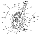
図1は本発明の実施形態を示しており、自動車のシャーシから分離されたホイールおよびそれに接続されたサスペンションの形態が示されており、それらは使用時にはシャーシに取り付けられる。 FIG. 1 shows an embodiment of the present invention, in which a wheel separated from an automobile chassis and a suspension connected thereto are shown, which are attached to the chassis in use.
したがって、リム14に装着されたタイヤ12を具備したホイール10は、ホイールハブ16にボルト固定されている。これは車軸18に取り付けられ、そのアセンブリはハブキャリア20に回転可能に支持されている。ドライブシャフト21(図示略)はディファレンシャルから車軸18まで通じており、それは駆動トルクをホイール10に伝達して、自動車を推進するためである。
Therefore, the
ハブキャリア20は、その回転を可能にする適切なベアリング(図示略)を具備した、車軸18およびハブ16のためのマウントと、マウントから内向きに延在した強化フランジと、を具備し、強化フランジはハブキャリア20に剛性を提供し且つサスペンション要素のための取り付け位置を提供している。上側フランジ22はハブキャリア20の上端から延在し、前側フランジ24および後側フランジ26の形式の2つの側方フランジを備えている。これらのフランジは、以下のように主サスペンションに接続されている。
The
第一に、逆転したウィッシュボーン28はシステムに縦方向の追従を提供している。これは通常の実施とは逆に逆転しており、シャーシへの単一の取り付け位置30を備え、そこから2つのウィッシュボーンアーム32,34が(個々に)、ハブキャリア20の個々の側方フランジ24,26の前側取り付け位置36および後側取り付け位置38に延在している。これらの前側および後側取り付け位置はロッド40の形式であり、そのロッドは側方フランジ24,26内の開口部を貫通し、ウィッシュボーンアーム32,34の端部において対応した円筒領域を貫通している。したがって、ウィッシュボーンアーム32,34はロッド40に固定され、ホイールが上昇および加工したときに、必要な相対回転を可能にしている。
First, the inverted
類似の円筒領域がシャーシ取り付け位置30に含まれており、それは垂直方向に向けられて、いくらかの前側/後側調節機能を与えている。これはゴムブッシュ44を介してシャーシの適切なスタッド42(図1では図示略)またはそのようなものに組み付けられており、全方向においてウィッシュボーンアーム28の制限された移動を可能にしている。
A similar cylindrical area is included in the
トレーリングリンク46は前側および後側追従を提供するために設けられている。これは、ゴムブッシュ52を介して類似のスタッド50に組み付けられた水平に配列された円筒リンク48によってシャーシに接続されている。これは、ホイール10が上昇および下降したときの垂直面内におけるトレーリングリンク46の容易な回転を可能にしており、他の方向におけるある回転をサスペンションジオメトリに適合させることも可能にしている。
A trailing
その他端において、トレーリングリンク46はロッド40の前端に取り付けられている。ロッド40の端部に取り付けられたUセクションブラケット54は、幾分より小さい円筒領域56をトレーリングアーム46の端部において収容している。ピン58はUセクション54および円筒領域56を備えたゴムブッシュを水平に貫通しており、トレーリングアーム46は前方向および後方向においてホイール10を抑制するが、上昇および下降動作を可能にしている。
At the other end, the trailing
第三および最終の主サスペンション要素はストラット60である。これは従来のバネおよびダンパユニットであり、上部マウント62(図1では図示略)を介してシャーシに、およびブラケット64を介してハブキャリア20に取り付けられ、ブラケットはストラット60の下端にクランプされて、前側フランジ24に2つの位置においてボルト固定されている。したがって、ストラットはハブキャリアを全体的に直立の配列に維持し、ホイール10に下向きの力を与えてホイールを路面と接触させ、ホイール10の上昇および下降移動を減衰している。
The third and final main suspension element is a
図2は一側からのシステムを図示している。ホイール10は図式的に示されており、ハブ16に組み付けられている。逆転されたウィッシュボーン28が示されており、ロッド40に取り付けられており、ロッドは自動車の前部に向かって上向きに傾斜されたことが見られている。同様に、トレーリングアーム46はシャーシマウント50からロッド40のUセクションブラケット54まで下向きに傾いている。ストラットはわずかに前方に傾いており、上部マウント62はブラケット64の幾分前にある。これらの角度および配向はサスペンションシステムのデザインにおいて調節されることが可能であり、それは所望のハンドリング特性を提供するためである。
FIG. 2 illustrates the system from one side. The
図3は上からシステムを示した図であり、逆転されたウィッシュボーン28の角度を図示している。後側ウィッシュボーンアーム34は前側アーム32よりも短く、それはシャーシへの取り付け位置30がホイール中心線よりも後側にあることを意味している。これはドライブシャフト21のための空間がホイールハブ16に到達し、取り付け位置30の前方を通過し、前側ウィッシュボーン32の上側になることを可能にしている。
FIG. 3 shows the system from above, showing the angle of the
図4は後方からのシステムを示しており、ドライブシャフト21は逆転されたウィッシュボーン28の上を通っている。
FIG. 4 shows the system from the rear, with
図5は、上述のサスペンションシステムが組み込まれたコンパクトタウンカーの後方からの概略的な図を示している。シャーシ66は必要な取り付け位置42を提供し、エンジン68とギアボックス70とを収容している。一組のドライブシャフト21はギアボックス70から両方向に外側に突出しており、自動車の両側のホイールハブ16に向かっている。1つのホイール10は各々のホイールハブ16に組み付けられ、各々のホイール10は上述のサスペンションシステムによって支持されており、逆転されたウィッシュボーン28、ストラット60、およびトレーリングアーム(図5においては図示略)を含んでいる。
FIG. 5 shows a schematic view from the rear of a compact town car incorporating the above suspension system. The chassis 66 provides the required mounting
図5から明白であるように、図示されたシステムは後方エンジン後輪駆動形態の後輪の必要性を満足させるように設計されている。しかしながら、前輪駆動(またはその他)のレイアウトの駆動輪または非駆動輪のように、他の形態においても応用され得る。 As is apparent from FIG. 5, the illustrated system is designed to meet the need for rear wheels in a rear engine rear wheel drive configuration. However, it can also be applied in other forms, such as driving wheels or non-driving wheels with a front wheel drive (or other) layout.
この「逆転ウィッシュボーン」システムは、独立したサスペンションシステムの乗車性およびハンドリングの利点を提供するだけでなく、(逆転ウィッシュボーン28およびトレーリングリンク46の)2つの部分のリンクが自動車の乗車性および快適性のための前後の追従と、ハンドリング制御(キャンバおよびトゥ制御)のための側方の追従と、を分離することを可能にしている。ストラット60を伴って、システム全体は極めて軽量であり、自動車側につき2つのみのリンクおよび自動車側につき3つのみの追従要素を具備しているため、低生産コストである。
This “reverse wishbone” system not only provides the ride and handling advantages of an independent suspension system, but the two-part link (of the
記載されたシステムも少数のシャーシへの取り付け位置のみを必要とし、それらがドライブシャフトから十分に離間されることを可能にしている。これは、システムが、部品の空間が制限され且つホイールがエンジン、ギアボックス等に密接して組み付けられた、小型で且つ効率的なタウンカーに特に適している。 The described system also requires only a few chassis mounting positions, allowing them to be sufficiently spaced from the drive shaft. This is particularly suitable for small and efficient town cars where the system is limited in part space and the wheels are closely assembled to the engine, gearbox, etc.
多くの変形が本発明の範囲から逸脱することなく上述の実施形態に加えられ得ることが、もちろん理解される。 Of course, it will be understood that many variations may be made to the above-described embodiments without departing from the scope of the invention.
10 ・・・ホイール、 12 ・・・タイヤ、 14 ・・・リム、 16 ・・・ホイールハブ、 18 ・・・車軸、 20 ・・・ハブキャリア、 21 ・・・ドライブシャフト、 22 ・・・上側フランジ、 24 ・・・前側フランジ、 26 ・・・後側フランジ、 28 ・・・ウィッシュボーン、 30・・・シャーシ取り付け位置、 32,34 ・・・ウィッシュボーンアーム、 36 ・・・前側取り付け位置、 38 ・・・後側取り付け位置、 42,50 ・・・スタッド、 44 ・・・ゴムブッシュ、 46 ・・・トレーリングリンク、 48 ・・・円筒リンク、 52 ・・・ゴムブッシュ、 66 ・・・シャーシ、 68 ・・・エンジン、 70 ・・・ギアボックス
DESCRIPTION OF
Claims (12)
自動車の走行方向において互いに離間された2つの位置において前記ハブキャリアに取り付けられたサポートアームであって、シャーシに固定するためのサポートアーム取り付け位置へと前記ハブキャリアに取り付けられた位置から内向きに前記自動車の中心線に向かって延在したサポートアームと、
該サポートアームの横方向においてアセンブリから延在し、前記シャーシに固定するためのトレーリングリンク取り付け位置へと向かったトレーリングリンクと、
のアセンブリを具備した自動車用サスペンションであって、
前記サポートアームの前記シャーシへの固定は前記シャーシに対して全方向における前記サポートアームの移動を可能にしており、
前記ハブキャリアは前後に配列された回動ピンを含み、該ピンは前記サポートアームの2つの回動位置を貫通しており、これによって2つの位置を画定し、前記トレーリングリンクは前記回動ピンの前端に連結されていることを特徴とする自動車用サスペンション。 A hub carrier,
A support arm attached to the hub carrier at two positions spaced apart from each other in the traveling direction of the automobile, wherein the support arm is attached to the chassis at a support arm attachment position for fixing to the chassis inward from the position attached to the hub carrier. A support arm extending toward the centerline of the vehicle ;
A trailing link extending from the assembly in a lateral direction of the support arm and toward a trailing link mounting position for securing to the chassis;
An automobile suspension comprising the assembly of
Fixing the support arm to the chassis allows movement of the support arm in all directions relative to the chassis ;
The hub carrier includes a pivot pin arranged in the front-rear direction, the pin passes through two pivot positions of the support arm, thereby defining two positions, and the trailing link is the pivot link. An automobile suspension characterized by being connected to a front end of a pin .
Applications Claiming Priority (3)
| Application Number | Priority Date | Filing Date | Title |
|---|---|---|---|
| GB0903590.8 | 2009-03-03 | ||
| GB0903590.8A GB2468302B (en) | 2009-03-03 | 2009-03-03 | Vehicle suspension |
| PCT/GB2010/000370 WO2010100412A1 (en) | 2009-03-03 | 2010-03-03 | Vehicle suspension |
Publications (3)
| Publication Number | Publication Date |
|---|---|
| JP2012519621A JP2012519621A (en) | 2012-08-30 |
| JP2012519621A5 JP2012519621A5 (en) | 2014-07-03 |
| JP5784509B2 true JP5784509B2 (en) | 2015-09-24 |
Family
ID=40566033
Family Applications (1)
| Application Number | Title | Priority Date | Filing Date |
|---|---|---|---|
| JP2011552500A Active JP5784509B2 (en) | 2009-03-03 | 2010-03-03 | Automotive suspension |
Country Status (10)
| Country | Link |
|---|---|
| US (1) | US8708359B2 (en) |
| EP (1) | EP2403727B1 (en) |
| JP (1) | JP5784509B2 (en) |
| BR (1) | BRPI1013235B1 (en) |
| CA (1) | CA2754287C (en) |
| ES (1) | ES2573502T3 (en) |
| GB (1) | GB2468302B (en) |
| MX (1) | MX2011009203A (en) |
| PL (1) | PL2403727T3 (en) |
| WO (1) | WO2010100412A1 (en) |
Families Citing this family (16)
| Publication number | Priority date | Publication date | Assignee | Title |
|---|---|---|---|---|
| EP2441602A1 (en) * | 2010-10-08 | 2012-04-18 | Ford Global Technologies, LLC | Wheel suspension with a spring-damper strut |
| US10160497B2 (en) * | 2011-02-01 | 2018-12-25 | Polaris Industries Inc. | All terrain vehicle |
| US9102205B2 (en) * | 2011-02-01 | 2015-08-11 | Polaris Industries Inc. | All terrain vehicle |
| US9469173B2 (en) * | 2011-11-14 | 2016-10-18 | Gordon Murray Design Limited | Vehicle suspension |
| GB2525901A (en) * | 2014-05-08 | 2015-11-11 | Gordon Murray Design Ltd | Vehicle suspension |
| GB201410154D0 (en) * | 2014-06-09 | 2014-07-23 | Gordon Murray Design Ltd | Vehicle impact structures |
| DE102016206220B4 (en) | 2016-04-14 | 2023-04-20 | Ford Global Technologies, Llc | Rear wheel suspension for motor vehicles |
| DE102016220786B4 (en) * | 2016-10-24 | 2024-03-28 | Ford Global Technologies, Llc | Rear suspension for motor vehicles |
| US11173808B2 (en) | 2016-12-22 | 2021-11-16 | Polaris Industies Inc. | Vehicle |
| USD835545S1 (en) | 2017-02-17 | 2018-12-11 | Polaris Industries Inc. | Off-road vehicle |
| US10493798B2 (en) | 2017-03-24 | 2019-12-03 | Cnh Industrial America Llc | Air strut suspension system for a self-propelled high ground clearance product applicator |
| US10343476B2 (en) * | 2017-06-08 | 2019-07-09 | Yujie Zhang | Golf cart front suspension lift kit |
| DE102018205429B4 (en) | 2018-04-11 | 2019-10-24 | Ford Global Technologies, Llc | Rear wheel suspension system of a motor vehicle, in particular of an electrically driven motor vehicle |
| US11207933B2 (en) | 2019-08-14 | 2021-12-28 | Yujie Zhang | Golf cart front suspension lift kit |
| DE112020004207T5 (en) * | 2019-09-05 | 2022-05-25 | Multimatic Inc. | Seamless vehicle suspension control arm |
| JP2022147151A (en) * | 2021-03-23 | 2022-10-06 | 本田技研工業株式会社 | suspension structure |
Family Cites Families (35)
| Publication number | Priority date | Publication date | Assignee | Title |
|---|---|---|---|---|
| US2556767A (en) * | 1946-10-23 | 1951-06-12 | Ford Motor Co | Independent wheel suspension |
| US3189118A (en) * | 1960-12-22 | 1965-06-15 | Ford Motor Co | Vehicle rear wheel suspension |
| CA994427A (en) | 1970-11-25 | 1976-08-03 | Medical Plastics | Plate electrode |
| JPS5027698Y2 (en) * | 1971-05-25 | 1975-08-16 | ||
| JPS5121494B2 (en) * | 1971-08-30 | 1976-07-02 | ||
| EP0000979B1 (en) * | 1977-08-13 | 1981-09-23 | GKN Group Services Limited | Rigid axle suspension system for a vehicle |
| JPS5830725Y2 (en) * | 1977-12-28 | 1983-07-07 | 本田技研工業株式会社 | Vehicle rear wheel suspension system |
| JPS5848366B2 (en) * | 1978-05-24 | 1983-10-28 | マツダ株式会社 | Automotive rear wheel suspension system |
| JPS5751508A (en) * | 1980-09-10 | 1982-03-26 | Mazda Motor Corp | Rear wheel suspension unit for automobile |
| BR8108870A (en) * | 1980-11-19 | 1982-10-13 | Ford Motor Co | MOTORIZED VEHICLE WHEEL SUSPENSION |
| DE3048794C1 (en) * | 1980-12-23 | 1982-08-12 | Daimler-Benz Ag, 7000 Stuttgart | Independent wheel suspension for motor vehicles |
| DE3048864C2 (en) * | 1980-12-23 | 1986-11-13 | Daimler-Benz Ag, 7000 Stuttgart | Axle, especially rear axle for passenger cars, with independently guided wheels |
| DE3119777A1 (en) | 1981-05-19 | 1982-12-16 | Dr.Ing.H.C. F. Porsche Ag, 7000 Stuttgart | Independent wheel suspension |
| JPS6111042Y2 (en) * | 1981-06-25 | 1986-04-08 | ||
| JPS58209605A (en) * | 1982-05-31 | 1983-12-06 | Mazda Motor Corp | Rear suspension for car |
| JPS58182810U (en) * | 1982-05-31 | 1983-12-06 | 日産自動車株式会社 | Rear suspension device |
| JPS58214469A (en) | 1982-06-07 | 1983-12-13 | Nissan Motor Co Ltd | Rear wheel steering device |
| DE3306432C2 (en) * | 1983-02-24 | 1986-12-11 | Ford-Werke AG, 5000 Köln | Independent wheel suspension for non-steered wheels of motor vehicles |
| DE3338644A1 (en) * | 1983-10-25 | 1985-05-02 | Bayerische Motoren Werke AG, 8000 München | INDEPENDENT WHEEL SUSPENSION FOR MOTOR VEHICLES |
| US4848788A (en) * | 1984-11-15 | 1989-07-18 | Ford Motor Company | Independent rear wheel suspension with offset connection between upper control arm and wheel carrier |
| FR2580555B1 (en) * | 1985-04-19 | 1989-04-21 | Renault | REAR AXLE WITH PULL ARM FOR MOTOR VEHICLE SUSPENSION |
| JPS61176007U (en) * | 1985-04-24 | 1986-11-01 | ||
| JPS6261809A (en) * | 1985-09-11 | 1987-03-18 | Nissan Motor Co Ltd | Strut type suspension device for vehicle |
| JPH052322Y2 (en) * | 1986-09-26 | 1993-01-21 | ||
| JPS63189808U (en) * | 1987-05-28 | 1988-12-06 | ||
| DE3826232A1 (en) * | 1987-08-03 | 1989-02-16 | Honda Motor Co Ltd | WHEEL SUSPENSION SYSTEM |
| US4969661A (en) * | 1987-08-24 | 1990-11-13 | Nissan Motor Co., Ltd. | Vehicular rear suspension system and rear end construction including same |
| FR2677928B1 (en) * | 1991-06-18 | 1993-08-27 | Renault | WHEEL HALF SUSPENSION WITH SUPERIMPOSED TRIANGLES. |
| DE4206896C2 (en) * | 1992-03-05 | 1994-09-01 | Bayerische Motoren Werke Ag | Wheel suspension for steerable wheels of motor vehicles |
| JP3464684B2 (en) | 1993-01-19 | 2003-11-10 | 本田技研工業株式会社 | Steering wheel suspension |
| JP2002046444A (en) * | 2000-08-02 | 2002-02-12 | Mazda Motor Corp | Rear suspension structure of vehicle |
| DE10133424A1 (en) * | 2001-07-10 | 2003-01-23 | Bayerische Motoren Werke Ag | Rear axle for vehicle has upper two of five individual rods set in front of spring and/or damper element mounted between vehicle superstructure and one of lower guide rods |
| US7360775B2 (en) * | 2005-04-28 | 2008-04-22 | Dana Heavy Vehicle Systems Group, Llc | SLA independent vehicle suspension with air bag springs |
| US7571918B2 (en) * | 2006-03-31 | 2009-08-11 | Honda Motor Company, Ltd. | Suspension arm for a vehicle |
| JP5005067B2 (en) * | 2010-05-28 | 2012-08-22 | 本田技研工業株式会社 | Suspension device |
-
2009
- 2009-03-03 GB GB0903590.8A patent/GB2468302B/en active Active
-
2010
- 2010-03-03 PL PL10711916.6T patent/PL2403727T3/en unknown
- 2010-03-03 WO PCT/GB2010/000370 patent/WO2010100412A1/en active Application Filing
- 2010-03-03 EP EP10711916.6A patent/EP2403727B1/en active Active
- 2010-03-03 MX MX2011009203A patent/MX2011009203A/en active IP Right Grant
- 2010-03-03 ES ES10711916.6T patent/ES2573502T3/en active Active
- 2010-03-03 BR BRPI1013235-0A patent/BRPI1013235B1/en active IP Right Grant
- 2010-03-03 JP JP2011552500A patent/JP5784509B2/en active Active
- 2010-03-03 US US13/254,286 patent/US8708359B2/en active Active
- 2010-03-03 CA CA2754287A patent/CA2754287C/en active Active
Also Published As
| Publication number | Publication date |
|---|---|
| CA2754287C (en) | 2017-05-02 |
| EP2403727A1 (en) | 2012-01-11 |
| US20120061937A1 (en) | 2012-03-15 |
| MX2011009203A (en) | 2011-10-24 |
| BRPI1013235B1 (en) | 2020-08-11 |
| WO2010100412A1 (en) | 2010-09-10 |
| BRPI1013235A2 (en) | 2016-04-05 |
| PL2403727T3 (en) | 2016-09-30 |
| GB0903590D0 (en) | 2009-04-08 |
| ES2573502T3 (en) | 2016-06-08 |
| JP2012519621A (en) | 2012-08-30 |
| GB2468302A (en) | 2010-09-08 |
| CA2754287A1 (en) | 2010-09-10 |
| EP2403727B1 (en) | 2016-03-02 |
| US8708359B2 (en) | 2014-04-29 |
| GB2468302B (en) | 2013-04-03 |
Similar Documents
| Publication | Publication Date | Title |
|---|---|---|
| JP5784509B2 (en) | Automotive suspension | |
| JP6979501B2 (en) | Vehicle suspension | |
| US6357769B1 (en) | Independent rear suspension system | |
| US9469173B2 (en) | Vehicle suspension | |
| US7635138B2 (en) | Frame integrated rear suspension | |
| EP2355987B1 (en) | Vehicle independent suspension | |
| EP1888355B1 (en) | Suspension systems | |
| US20220234663A1 (en) | Modular front drivetrain assembly | |
| CN114919355A (en) | Multi-link mid-height suspension assembly for motor vehicles | |
| US11958535B2 (en) | Modular front drivetrain assembly | |
| US11673443B2 (en) | Suspension system for electric heavy-duty vehicle | |
| CN111655520B (en) | Wheel suspension device for a motor vehicle, holding device and motor vehicle | |
| KR100398211B1 (en) | Partial independence type vehicle suspension system | |
| GB2607076A (en) | Vehicle wheel suspension | |
| KR20050060702A (en) | Suspension of mcpherson strut type |
Legal Events
| Date | Code | Title | Description |
|---|---|---|---|
| A621 | Written request for application examination |
Free format text: JAPANESE INTERMEDIATE CODE: A621 Effective date: 20130226 |
|
| A977 | Report on retrieval |
Free format text: JAPANESE INTERMEDIATE CODE: A971007 Effective date: 20140210 |
|
| A131 | Notification of reasons for refusal |
Free format text: JAPANESE INTERMEDIATE CODE: A131 Effective date: 20140218 |
|
| A524 | Written submission of copy of amendment under article 19 pct |
Free format text: JAPANESE INTERMEDIATE CODE: A524 Effective date: 20140519 |
|
| A02 | Decision of refusal |
Free format text: JAPANESE INTERMEDIATE CODE: A02 Effective date: 20141021 |
|
| A521 | Request for written amendment filed |
Free format text: JAPANESE INTERMEDIATE CODE: A523 Effective date: 20150218 |
|
| A911 | Transfer to examiner for re-examination before appeal (zenchi) |
Free format text: JAPANESE INTERMEDIATE CODE: A911 Effective date: 20150417 |
|
| TRDD | Decision of grant or rejection written | ||
| A01 | Written decision to grant a patent or to grant a registration (utility model) |
Free format text: JAPANESE INTERMEDIATE CODE: A01 Effective date: 20150622 |
|
| A61 | First payment of annual fees (during grant procedure) |
Free format text: JAPANESE INTERMEDIATE CODE: A61 Effective date: 20150722 |
|
| R150 | Certificate of patent or registration of utility model |
Ref document number: 5784509 Country of ref document: JP Free format text: JAPANESE INTERMEDIATE CODE: R150 |
|
| R250 | Receipt of annual fees |
Free format text: JAPANESE INTERMEDIATE CODE: R250 |
|
| R250 | Receipt of annual fees |
Free format text: JAPANESE INTERMEDIATE CODE: R250 |
|
| R250 | Receipt of annual fees |
Free format text: JAPANESE INTERMEDIATE CODE: R250 |
|
| R250 | Receipt of annual fees |
Free format text: JAPANESE INTERMEDIATE CODE: R250 |
|
| R250 | Receipt of annual fees |
Free format text: JAPANESE INTERMEDIATE CODE: R250 |
|
| R250 | Receipt of annual fees |
Free format text: JAPANESE INTERMEDIATE CODE: R250 |
|
| S533 | Written request for registration of change of name |
Free format text: JAPANESE INTERMEDIATE CODE: R313533 |
|
| R350 | Written notification of registration of transfer |
Free format text: JAPANESE INTERMEDIATE CODE: R350 |