JP5782104B2 - Method and apparatus for low loss, mode field matched coupling to multi-core fiber - Google Patents
Method and apparatus for low loss, mode field matched coupling to multi-core fiber Download PDFInfo
- Publication number
- JP5782104B2 JP5782104B2 JP2013500185A JP2013500185A JP5782104B2 JP 5782104 B2 JP5782104 B2 JP 5782104B2 JP 2013500185 A JP2013500185 A JP 2013500185A JP 2013500185 A JP2013500185 A JP 2013500185A JP 5782104 B2 JP5782104 B2 JP 5782104B2
- Authority
- JP
- Japan
- Prior art keywords
- core
- fiber
- pedestal
- core fiber
- diameter
- Prior art date
- Legal status (The legal status is an assumption and is not a legal conclusion. Google has not performed a legal analysis and makes no representation as to the accuracy of the status listed.)
- Active
Links
Images


Classifications
-
- G—PHYSICS
- G02—OPTICS
- G02B—OPTICAL ELEMENTS, SYSTEMS OR APPARATUS
- G02B6/00—Light guides; Structural details of arrangements comprising light guides and other optical elements, e.g. couplings
- G02B6/02—Optical fibres with cladding with or without a coating
- G02B6/02042—Multicore optical fibres
-
- G—PHYSICS
- G02—OPTICS
- G02B—OPTICAL ELEMENTS, SYSTEMS OR APPARATUS
- G02B6/00—Light guides; Structural details of arrangements comprising light guides and other optical elements, e.g. couplings
- G02B6/24—Coupling light guides
- G02B6/26—Optical coupling means
- G02B6/262—Optical details of coupling light into, or out of, or between fibre ends, e.g. special fibre end shapes or associated optical elements
-
- Y—GENERAL TAGGING OF NEW TECHNOLOGICAL DEVELOPMENTS; GENERAL TAGGING OF CROSS-SECTIONAL TECHNOLOGIES SPANNING OVER SEVERAL SECTIONS OF THE IPC; TECHNICAL SUBJECTS COVERED BY FORMER USPC CROSS-REFERENCE ART COLLECTIONS [XRACs] AND DIGESTS
- Y10—TECHNICAL SUBJECTS COVERED BY FORMER USPC
- Y10T—TECHNICAL SUBJECTS COVERED BY FORMER US CLASSIFICATION
- Y10T29/00—Metal working
- Y10T29/49—Method of mechanical manufacture
- Y10T29/49826—Assembling or joining
Description
本発明は、基本的にマルチコアファイバへの低損失でモードフィールドが整合された結合のための方法、および装置に関する。
本出願は以下の米国仮出願特許の優先権の利益を請求し、その仮出願特許は本発明の出願の譲受人によって保有され、かつそのすべてが参照のためにここに引用される。
2010年3月16日に出願され、”低損失で、モードフィールドが整合されたマルチコアファイバカプラー”と題される米国仮出願特許番号No.61/314,182.
The present invention relates generally to a method and apparatus for low loss, mode field matched coupling to multi-core fibers.
This application claims the benefit of the priority of the following US provisional application patent, which is owned by the assignee of the present application and is hereby incorporated by reference in its entirety:
Filed on March 16, 2010 and entitled “Low Loss, Mode Field Matched Multicore Fiber Coupler”. 61/314, 182.
大容量の光ネットワークに対して拡大し続ける要求のために、ネットワークの容量を拡大するための方法として、マルチコアファイバ(MCF)を採用するシステムの設計、および構築に対する関心が高まっている。さらに、低コストで、ファイバ数の多い、高密度ケーブルが実用的な光加入者基線を建設するために必要である。同様に、ケーブルの直径、および/あるいは長さによってもたらされる制約を克服するための方法としてMCFが調査されつつある。 Due to the ever-increasing demand for high-capacity optical networks, there is a growing interest in designing and building systems that employ multi-core fiber (MCF) as a way to expand network capacity. In addition, low cost, high fiber count, high density cables are necessary to construct a practical optical subscriber baseline. Similarly, MCF is being investigated as a way to overcome the constraints imposed by cable diameter and / or length.
性能、および最終的にMCFベースのシステムの実用性に重大な影響を与えると思われるひとつの問題は、MCFコアの中を伝播する個々の信号を多重化し、分波するためのこれらのシステムの能力である。いくつかの方式が提案されてきているが、これらの方式は複雑で、かつ多数の構成要素を必要とする。 One issue that may have a significant impact on performance, and ultimately the practicality of MCF-based systems, is that these systems for multiplexing and demultiplexing individual signals propagating through the MCF core. Is ability. Several schemes have been proposed, but these schemes are complex and require a large number of components.
さらに、一般的に言えば、通常ほぼ125μm程度の外径を備える従来型のシングルコア(single−core)ファイバの外径と同程度の外径を備えることがMCFに対して好都合である。一般的なMCFにおいては、適当な外径を達成するために、コアとコアとの間隔はほぼ40μm程度である。複数のシングルコアファイバを同程度の外径を備える単一のMCFのコアに結合し、適切なコアの整列を達成するためにはシングルコアファイバのリード端部の外径の低減を必要とする。低減の技術は、例えば、機械的な方法(例えば研磨すること)、および化学的な方法(例えばエッチング)を含んでよい。 Furthermore, generally speaking, it is advantageous for the MCF to have an outer diameter comparable to that of a conventional single-core fiber, which usually has an outer diameter of approximately 125 μm. In a general MCF, in order to achieve an appropriate outer diameter, the distance between the cores is approximately 40 μm. Coupling multiple single-core fibers to a single MCF core with comparable outer diameters and reducing the outer diameter of the single core fiber lead ends to achieve proper core alignment . Reduction techniques may include, for example, mechanical methods (eg, polishing) and chemical methods (eg, etching).
一組のシングルコアファイバをツインコア(twin−core)MCFに結合するための技術が提案されている。ツインコアMCFのコア間隔に整合するように先細にされる組立体を形成するために、二本のシングルコアファイバが二穴の毛細管に挿入される。しかし、MCFの潜在能力を全面的に利用するためには多数のコア、例えば7本、あるいはそれ以上を備えるMCFの利用を必要とする。コアはシングルモードであるかもしれない、あるいはいくつか、あるいは多数のモードを有するかもしれない。必要とされる先細率、および大容量信号搬送に重要である光クロストークなどの光学的な特性が考慮されていなかったために、上に述べられた方法はこのようなMCFの利用に適していない。ある設計形態においては、ステップインデックス(step−index)ファイバを先細にすることはモードフィールド径を増加させ、それは結合損失の増加をもたらすことが知られている。 Techniques have been proposed for coupling a set of single core fibers to a twin-core MCF. To form an assembly that is tapered to match the core spacing of the twin-core MCF, two single-core fibers are inserted into a two-hole capillary. However, in order to make full use of the potential of MCF, it is necessary to use MCF having a large number of cores, for example, seven or more. The core may be single mode, or may have some or many modes. The methods described above are not suitable for use with such MCFs because the required taper and the optical properties such as optical crosstalk that are important for large capacity signal transport were not considered. . In certain designs, it is known that tapering a step-index fiber increases the mode field diameter, which results in increased coupling loss.
米国特許第5,864,644号明細書に示されるような先細にしたファイバ束(TFB)は、ポンプ光を結合するためだけでなく、増幅段間におけるLP01信号モードへの遷移を提供するために使用されている。この技術は、複数の信号コアをMCFへ結合することに対しては満足できるほどに拡張されてはいない。一つの理由は、束を先細にする際の表面張力によって、束の外側表面がほぼ円形になるように滑らかになる傾向があることである。そのため、先細にされたコアのモードフィールド径を対応するMFCコアのモードフィールド径に整合させることはできるが、表面張力の影響によって束の外側のコアに顕著な変形がもたらされる。これらの変形が、コア及びモードフィールド形状を変化させ、その結果、過度の結合損失をもたらし、また、隣接するコアの間のクロストーク源となることがあった。 U.S. Patent No. 5,864,644 Pat tapering the fiber bundle as shown (TFB), not only for coupling the pump light to provide a transition to the LP 01 signal mode between amplifier stages Has been used for. This technique, for it to join a plurality of signal cores to MCF not been extended to more satisfactory. One reason is, by surface tension when tapering the bundle is that the outer surface of the bundle there is a smooth tends to be substantially circular. Therefore, although the mode field diameter of the core is tapered may be to match the mode field diameter of the corresponding MFC cores are al was also is remarkable deformation outside the core of the flux by the influence of surface tension . These variations may alter the core and the mode field shape, as a result, lead to excessive coupling loss, also had to be a crosstalk source between adjacent cores.
本発明の態様は、複数の終端部のそれぞれをマルチコアファイバの対応する個々のコアに接続するための装置、および方法に関する。複数の終端部のそれぞれに対応する長さのシングルコアファイバが与えられ、その場合において、シングルコアファイバが先細にされるときに、許容範囲内で一定のモードフィールド径、およびモードコンテント(modal content)などのモード特性を保持するようにシングルコアファイバが構成される。さらに、後端、前端、およびその間に延びる複数の孔のある胴体を備えるカプラが与えられ、その場合において、対応する孔はカプラ胴体の後端部で対応する長さのシングルコアファイバを密接して受ける寸法とされ、かつその場合において、複数の孔はマルチコアファイバのコアの構成に整合する構成を備える。所定長さのシングルコアファイバのそれぞれのリード端部がカプラ胴体の後端の対応する孔に挿入され、組立体を形成するために、挿入された所定長さのシングルコアファイバの周囲にカプラ胴体が縮径される。組立体の前端が先細にされ、シングルコアファイバのコアが、マルチコアファイバのコアの構成と整合する構成に配列されるように前端面が形成される。所定長さのシングルコアファイバのそれぞれの末端が対応する終端部に接続され、シングルコアファイバの対応するコアがマルチコアファイバの個々のコアと一直線になるように、組立体の前端面がマルチコアファイバの端面に接続される。 Aspects of the invention relate to an apparatus and method for connecting each of a plurality of terminations to a corresponding individual core of a multi-core fiber. A single-core fiber of a length corresponding to each of a plurality of terminations is provided, in which case when the single-core fiber is tapered, a constant mode field diameter and mode content (modal content) within an acceptable range. The single core fiber is configured to maintain the mode characteristics such as In addition, a coupler is provided that includes a rear end, a front end, and a body with a plurality of holes extending therebetween, in which case the corresponding holes closely contact a single core fiber of a corresponding length at the rear end of the coupler body. In this case, the plurality of holes have a configuration that matches the configuration of the core of the multicore fiber. Each lead end of a single core fiber of a predetermined length is inserted into a corresponding hole in the rear end of the coupler body, to form an assembly, the coupler body around the inserted single core fiber of the predetermined length Is reduced in diameter. The front end face is formed such that the front end of the assembly is tapered and the core of the single core fiber is arranged in a configuration that matches the core configuration of the multi-core fiber. Each end of a single-core fiber of a given length is connected to the corresponding end, and the front end face of the assembly is aligned with the individual cores of the multi-core fiber so that the corresponding core of the single-core fiber is aligned Connected to the end face.
本発明の態様は、複数のシングルコアファイバ(SCF)をマルチコアファイバ(MCF)に結合するための構造、および方法に関し、その場合においてそれぞれのSCFコアは対応する別個のMCFコアに結合される。 Aspects of the invention relate to structures and methods for coupling a plurality of single core fibers (SCFs) to multicore fibers (MCFs), wherein each SCF core is coupled to a corresponding separate MCF core.
本発明の例示的な実行例が、2010年3月16日に出願され、本発明の出願の譲受人に保有され、参照のためにそのすべてがここに引用される、米国仮特許出願第61/314,184号明細書に記載される形式の7コアMCF設計の個々のコアへの結合を提供することに関連して以下に述べられる。しかしながら、記載される方法は、異なる数のコア、異なるコア、およびクラッド構造、異なるコア構成、および類似のものを備える他の形式のマルチコアファイバである他の状況において適用できるということが評価されるであろう。 An exemplary implementation of the present invention is filed on March 16, 2010 and is owned by the assignee of the present application, which is hereby incorporated by reference in its entirety. The following is described in connection with providing coupling to individual cores of a seven-core MCF design of the type described in US / 314,184. However, it is appreciated that the described method can be applied in other situations where there are other types of multi-core fibers with different numbers of cores, different cores and cladding structures, different core configurations, and the like. Will.
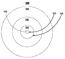
図1A、および1Bは、共通のクラッド領域24内の7つのコア領域22a−gの配列からなる、米国仮特許出願第61/314,184号明細書に記載される形式の例示的な7コアMCF20の断面、および等角投影図をそれぞれ示す。第一のコア領域22aはファイバの中心部に配される。6つのコア領域22b−gは中心部のコア22aを取り囲む六角形26として配置される。7つのコア領域22a−gは、それらの長軸28に沿って所定の長さのMCF20の下流にそれぞれの光通信を搬送するように構成される。
1A and 1B are exemplary seven cores of the type described in US Provisional Patent Application No. 61 / 314,184, which consists of an array of seven
図2は、結合状況40の図であって、寸法通りには描かれていないが、本発明のいろいろな態様の説明のための骨組みとして与えられる。状況40において、結合は、四角T1−T7、および7コアのマルチコアファイバMCF1の対応する個々のコアによって表される7つの終端部のそれぞれの間に与えられるべきものである。目下の議論の目的のために、用語「終端部(terminal)」は光信号を搬送する何らかの装置の接続点を意味し、例えば、ファイバ、および非ファイバ装置はもちろん、表面実装光放射ダイオード、あるいは類似のもののようなファイバベースの装置を含むことができる。
FIG. 2 is an illustration of the
目下の議論のために、MCF1の個々のコアは、挿入図51aに示されるように、識別文字A−Gが任意に割り当てられ、対応する終端部T1−T7に接続される。シングルコアファイバSCF1−SCF7は、断面に示されるように、ピッグテールコネクタとして与えられる。ピッグテールファイバSCF1−SCF7のそれぞれは終端部T1−T7に接続するための末端、およびマルチコアファイバMCF1への接続のためのリード端を備える。現在の例において、シングルコアファイバSCF1−SCF7とマルチコアファイバMCF1は実質的に等しい外径を備えると仮定される。しかし、一つ以上のシングルコアファイバがマルチコアファイバの外径よりも異なる外径を備える用途において、必要に応じて適宜修正されて本発明の態様を実行することも可能であろう。さらに、シングルコアファイバSCF1−SCF7の対応する長さがゼロ、あるいはほぼゼロである用途において、必要に応じて適宜修正されて本発明の態様を実行することが可能であろう。(したがって、ここで使われるように、用語シングルコアファイバの「対応する長さ」はシングルコアファイバの長さがゼロ、あるいはほぼゼロを含む。) For the current discussion, the individual cores of MCF1 are arbitrarily assigned identification letters A-G and connected to the corresponding terminations T1-T7, as shown in the inset 51a. Single core fibers SCF1-SCF7 are provided as pigtail connectors, as shown in the cross section. Each of the pigtail fibers SCF1-SCF7 includes a terminal end for connection to the terminal end T1-T7 and a lead end for connection to the multi-core fiber MCF1. In the current example, it is assumed that the single core fiber SCF1-SCF7 and the multicore fiber MCF1 have substantially equal outer diameters. However, in applications where one or more single-core fibers have an outer diameter different than the outer diameter of the multi-core fiber, it will be possible to implement the aspects of the invention with appropriate modifications as needed. Further, in applications where the corresponding length of the single core fibers SCF1-SCF7 is zero or nearly zero, it would be possible to implement the aspects of the invention with appropriate modifications as needed. (Thus, as used herein, the term “corresponding length” of a single core fiber includes zero or nearly zero length of the single core fiber.)
例示の目的で、さらに図2はそれぞれのなされるべき接続を点線で示して、シングルコアファイバの端面41−47、およびマルチコアファイバの端面51の図を与える。以下に述べられるように、本発明の態様はそれぞれのSCFコア1−7を個々のMCFコアA−Gに接続するための構造、および方法を提供する。
For illustrative purposes, FIG. 2 further provides a view of single-core fiber end face 41-47 and multi-core
目下の例において、MCFの個々のコアは同じ特性を備えるということが注目されるべきである。しかし、記述されている構造、および方法は、一つ以上の個々のコアが他のコアの特性と異なる特性を備えるMCFを用いて、必要に応じて適宜修正されて実行されてもよいことが評価されるであろう。そのような場合には、異なる特性を備える個々のコアと適切な整合を提供するために対応するSCFを修正することが必要かもしれない。 It should be noted that in the current example, the individual cores of the MCF have the same characteristics. However, the described structures and methods may be implemented with one or more individual cores modified as appropriate using MCFs having characteristics different from those of other cores. Will be appreciated. In such cases, it may be necessary to modify the corresponding SCF to provide proper alignment with individual cores with different characteristics.
許容範囲内の低い接合損失、および信号がカプラを通過するときに(必要に応じて)誘起されるクロストークがほとんど、あるいは全くないこと、あるいはそれぞれのSCFコアを対応するMCFコアへ接続する上ででモードコンテント(mode content)の変化がほとんど、あるいは全くないことなど、乱れのないモード特性を達成するために、以下の基準:モードフィールドの整合、個々のコアの正確な配列、および正確に構成されたコアの幾何学的形状を満たすことが最も重要である。以下に述べられるように、これらの基準、およびその他のものが本発明の態様によって対処され、それは(1)マルチホールファイバカプラ(MHFC)としてここに参照される結合装置;(2)所与の先細率で許容範囲内において、選択されたモード特性を保持するように設計されているSCF;および(3)記述されたMHFCとモードフィールド保持ファイバを用いる結合方法を含む。 Low tolerable junction loss and little or no crosstalk induced (if necessary) when the signal passes through the coupler, or connecting each SCF core to the corresponding MCF core In order to achieve undisturbed mode characteristics, such as little or no change in mode content, the following criteria: mode field alignment, exact alignment of individual cores, and accurately It is most important to meet the geometry of the constructed core. As described below, these criteria, and others, are addressed by aspects of the present invention, which are (1) a coupling device referred to herein as a multi-hole fiber coupler (MHFC); (2) a given SCF designed to retain selected mode characteristics within taper and acceptable range; and (3) a coupling method using MHFC and mode field retaining fiber as described.
目下の議論は以下のように構成されている。
1.マルチホールファイバカプラ
2.モードフィールド保持ファイバ
3.結合方法
4.結論
The current discussion is organized as follows.
1.
1.マルチホールファイバカプラ
本発明の態様は、記述される結合方法において、コア対コアの配列はもちろん、モード内容、モード形状、およびモードフィールド径の整合を提供するモード保持、先細マルチホールファイバカプラ(MHFC)に関する。
1. Multi-Hole Fiber Coupler An aspect of the present invention is a mode retention, tapered multi-hole fiber coupler (MHFC) that provides matching of mode content, mode shape, and mode field diameter as well as core-to-core arrangement in the described coupling method. )
図3は、本発明の態様によるMHFC60の第一の例の断面を示す。MHFC60は、複数の孔64a−gを備える大径のファイバ62、あるいは類似の物体、からなる。ファイバ62、および孔64a−gの寸法、および構成は、SCF、およびMCFの寸法、個々のMCFコアの構成、および終端部の構成を含む数多くの要因によって決定される。
FIG. 3 shows a cross section of a first example of an MHFC 60 according to an aspect of the present invention. The
以下に記述されるように、ピッグテールSCFのリード端部がMHFC60の後端面の孔64a−gの中にそれらを挿入することによってMHFC60の中に装着される。したがって、孔64ピッグテールSCFの直径よりもわずかに大きい直径を備える寸法とされる。目下の例においては、SCFそれぞれは直径125μmであり、対応する孔は直径150μmである。特定の用途によっては、異なる直径を備えるひとつ以上のファイバを用いることも可能であるということが注目されるべきである。それに応じて対応する孔の直径は修正されるであろう。さらに、コアの間の間隔は相対的に一定であり、規則的であり得るが、あるいは変わることが出来る。例えば、コア間のクロストークを制御するために孔間隔が可変であってよいが、当然ながらMCFのコアの幾何学的形状が整合していなければならない。
As described below, the lead end of the pigtail SCF is mounted in the
以下にさらに議論されるように、MHFC胴体は、組立体を形成するために孔64に挿入されたSCFの周りに縮径され、それから先細にされ、マルチコアファイバに接合される。それに応じてMHFCを作るために使われる材料が選択される。目下の例においては、MHFCはドープされていないシリカ(SiO2)から作られ、それは以下に記述されるSCFのクラッド領域を作るするために使われる同じ材料である。さらに、所与の状況によってMHFCを作るために使われる材料を修正する、あるいは異なる材料、あるいは材料の組み合わせを用いることも可能であろう。そのような他の材料は、例えば、カルコゲナイドガラスのような無酸素ガラス;ドープされた、およびドープされないシリカファイバ;および類似のものを含む。 As will be discussed further below, the MHFC fuselage is reduced in diameter around the SCF inserted into hole 64 to form the assembly, then tapered and joined to the multi-core fiber. Accordingly, the material used to make the MHFC is selected. In the current example, the MHFC is made from undoped silica (SiO 2 ), which is the same material used to make the SCF cladding region described below. Furthermore, it may be possible to modify the material used to make the MHFC or to use a different material or combination of materials depending on the given situation. Such other materials include, for example, oxygen-free glasses such as chalcogenide glasses; doped and undoped silica fibers; and the like.
孔64a−gの構成は、SCFが結合されるべきMCFの個々のコアの構成によって決定される。特に、孔の構成はMCFコアの構成に相似であるように選択される。したがって、SCF−MHFC組立体がMCFへの接合のために先細にされ、割られるときに、組立体の前端面のSCFコアの幾何学的配置がMCFのそれと整合する。
The configuration of the
図3に示されるMHFC60は、図1、および図2に示されるMCFのような、7コアMCFに対応し、個々のコアはMHFC60の孔64の幾何学的形状に整合するようにに準じて構成される。
The
図4は、本発明のさらなる態様によるMHFC80の第二の例の断面を示す。MHFC80は長方形状に配置された孔84を含む大径ファイバ82からなる。図4は、記述される方法の一つの特別な長所が、例えば正方形、長方形、およびその他、幾何学的形状、および孔のパターンに対する柔軟性であることを示している。MCFの外側の形状は円形でなくてもよい。このことがいくつかの利点を生み出す:(a)非円形のファイバは曲げに対して好ましい方向性を備え、コア中に導かれるモード有効屈折率(modal effective index)の曲げに起因する歪みのような任意の曲げに起因する影響を制御することが出来る;(b)例えば、ファイバの非円形の外側形状は表面実装装置に直接的に結合するために、より容易に位置合わせが出来る;(c)非円形の外側幾何学的形状は、個々のコアの同一性を識別するためのマーカーとしての役目を果たす外側の特性によって、回転の方向付けを容易にすることが出来る。
FIG. 4 shows a cross section of a second example of
図5は、MHFC60(図3)の等角投影図を示し、本発明のさらなる態様を図解する。図5に示されるように、MHFCは後端部72、および前端部74を備える胴体70からなる。孔76がMHFC胴体の後端部72と前端部74との間に延びる。
FIG. 5 shows an isometric view of MHFC 60 (FIG. 3) and illustrates a further aspect of the present invention. As shown in FIG. 5, the MHFC includes a
図5に示される本発明の態様により、MHFCの前端部74はピッグテールSCFとの組立体に先立ち、”あらかじめ先細にされる”。特に、MHFC60の前端部74は、孔76の直径がピッグテールSCFの直径よりもわずかに小さいようにより細く先細に(down−tapered)されている。したがって、ピッグテールSCFがその対応する孔に差し込まれるときに、孔の長さ方向へのそのピッグテールの進行は途中で止められる。
In accordance with the embodiment of the invention shown in FIG. 5, the
MHFCをあらかじめ先細にすることには多くの理由がある。あらかじめ先細にすることは、MHFCの中のSMTファイバの正確な屈折率の設定(indexing)を可能にする。加えて、MHFC内のすべてのファイバの良好な同心性を保持することを助ける。 There are many reasons for tapering the MHFC in advance. Pre-tapering allows accurate indexing of the SMT fiber in the MHFC. In addition, it helps to maintain good concentricity of all fibers in the MHFC.
図5に示される例において、MHFCは直径750μmを備えるファイバから作られ、MHFCの前端部は直径575μmまであらかじめ先細にされる。孔76は後部の直径150μm、および前部の直径115μmを備える。
In the example shown in FIG. 5, the MHFC is made from a fiber with a diameter of 750 μm and the front end of the MHFC is pre-tapered to a diameter of 575 μm. The
2.MFD保持ファイバ
装置の第二の要素は、許容範囲内で大きな先細比のすべてにわたって少なくとも先細、および先細でない端部で同じモードフィールド径(MFD)を実質的に保持可能であり、かつほとんど、あるいはまったく誘起されたクロストークを見せない、特別に設計されたシングルコアファイバからなる。
2. The second element of the MFD holding fiber device is capable of substantially holding the same mode field diameter (MFD) at least at a tapered and non-tapered end over all of the large taper ratios within acceptable limits and little or It consists of a specially designed single-core fiber that does not show any induced crosstalk.
図6Aは、本発明によるMFD保持シングルモードファイバ100の断面を示し、図6Bは以下に記述されるようにMHFCと溶着され、4:1の比率まで先細にされた後のファイバ100’の断面を示す。図7A、および7Bは、図6A、および6Bに示される非先細、および先細ファイバそれぞれの屈折率プロファイル120/120’、およびLP01パワー分布関数140/140’を示す。
FIG. 6A shows a cross section of an MFD holding
図6A、および7Aに示されるように、ファイバは以下の領域を備える修正されたステップインデックスプロファイルを備える:中心部コア領域102/122、台座領域104/124、内側クラッド領域106/126、および落ち込んだ(depressed)外側クラッド領域108/128。特別の用途によっては、落ち込んだ外側クラッド領域108/128無しに本発明の態様を実行することが可能であってよいことが注目されるべきである。以下に記述されるように、コア、台座、および内側クラッドは所与の先細率のすべてにわたって実質的に一定のままであるモードフィールド径を生成するように結合する。落ち込んだ外側のクラッド領域108/128は光学的なモードフィールド分布の半径方向の広がりを抑制することによってクロストークを低減するために与えられる。
As shown in FIGS. 6A and 7A, the fiber comprises a modified step index profile comprising the following regions: a
図7Aの屈折率プロファイル120は非先細領域に対してそれぞれの半径、および屈折率を示す。目下の議論の目的のために、領域の屈折率はそれぞれのファイバ領域に対する屈折率の差Δn、つまりファイバ領域の屈折率マイナス内側クラッドの屈折率として表される。
The
図6A、および7Aから、約8μmの半径を備える第一の導波路103/123はコア102/122と台座104/124との間の境界によって作られるということが見られよう。約32μmの半径を備える第二の導波路105/125は台座104/124と内側クラッド106/126との間の境界によって作られる。非先細ファイバにおいては、1310nm/1550nmの範囲の波長におけるLP01モードは、導波路からいくらかの光の漏れを伴って第一の導波路によって閉じ込められる。ベストフィッテングガウス型アプローチ(best−fitting Gaussian approach)を用いて、モードフィールド直径が約10.25μmであると決定される。したがって、非先細ファイバにおいて、直径が32μmである第二の導波路はモードフィールド径に重大な影響を及ぼさないということが理解されよう。
It can be seen from FIGS. 6A and 7A that the
以下に記述されるように、シングルコアファイバはMHFCの中に挿入され、それから組立体を形成するためにMHFCはシングルコアファイバの周囲に縮径される。それから組立体はマルチコアファイバの端面の直径に整合するように先細にされる。したがって、図6Bの断面、および図7Bの屈折率プロファイルは、MHFCの胴体110’/130’の一部により取り囲まれる先細にされたファイバ領域102’/130’、104’/124’、106’/126’、108’/128’を示す。
As described below, the single core fiber is inserted into the MHFC, and then the MHFC is reduced in diameter around the single core fiber to form an assembly. The assembly is then tapered to match the diameter of the end face of the multicore fiber. Thus, the cross-section of FIG. 6B, and the refractive index profile of FIG. 7B, result in tapered
台座領域104、ファイバが先細にされるときにファイバのモードフィールド直径を保持する。第一の導波路103/123が8μmより小さい直径に先細にされるとき、信号は第一の導波路103/123によってあまり強くなく導かれ、そのためにモードフィールド直径を増加させる傾向になる。しかし、第二の導波路105/125も減少する。最初に、第二の導波路105/125の直径は約32μmであり、したがってモードフィールド直径に著しい影響を与えるにはあまりにも大きい。外側の導波路が先細にされて直径が8μmに近づくにしたがい、ますますモードフィールド特性に影響を及ぼす。正味の結果は、ファイバのモードフィールドは選択された先細率全体にわたって、前端部と後端部との間で許容される範囲内で実質的に同一なままである。したがって、4:1の比率に先細にされたファイバのモードフィールド直径は約9.84μmである。
図8は、ファイバ100に対するモードフィールド直径と先細率との間の関係を示すグラフ160である。プロット162に表されるように、モードフィールド直径は、0.6から4.2の範囲の先細率全体にわたって約11.25μmの最大値から約9.40μmの最小値まで変化する。したがって、ファイバが先細にされるときに、そのモードフィールド直径は、許容範囲内で実質的に一定である。この例において、変化は十分に小さく、モードフィールド直径の不整合に起因する結合損失は小さい(すなわち、0.5dBよりも小さい)ということが注目されるべきである。[0.02は達成が困難であろう]
FIG. 8 is a
もし特定の用途がより小さい許容範囲を必要とするのであれば、それにしたがってファイバの構成が修正されてもよい。例えば、第二の台座が加えられてもよい。 If a particular application requires a smaller tolerance, the fiber configuration may be modified accordingly. For example, a second pedestal may be added.
本発明の更なる態様はクロストークの問題に関する。いくつかの設計において、MCFのクロストークは性能を引き下げる潜在的要因のひとつである。そのために、これらの設計は、MHFCを先細にする間にひとつのコアからその隣への任意の漏れを最小にする必要がある。したがって、フッ素がドープされたドープシリカのような低屈折率材料で作られる外側のクラッド領域108/128が与えられる。図9のグラフ180に示されるように、ダウンドープされた(down−doped外側クラッド領域108/128の外側のLP01パワーの部分は本質的にゼロに等しい。
A further aspect of the invention relates to the problem of crosstalk. In some designs, MCF crosstalk is one of the potential factors that degrade performance. Therefore, these designs need to minimize any leakage from one core to its neighbor while tapering the MHFC. Thus, an
他の方法、および材料がダウンドープされた外側クラッド領域108/128を構成するために使われてもよい。例えば、それは環状の空孔、あるいは気泡、あるいは他の適当な低屈折率構造によって同程度の結果を達成することが可能である。孔、あるいはくぼみを含む領域は、台座を越えてたまたま侵入する任意の光を散乱させ、さらにクロストークを低減するという付加的な利点を提供する。
Other methods and materials may be used to construct the down doped
MCFのコアは多数のモードをサポートすることができるので、シングルコアファイバ、およびMHFCのコアもまた多数のモードをサポートするべきである。それぞれのモードが異なる光信号を搬送する場合には、シングルコア、およびマルチコアファイバのモードコンテンツはまったく同じはずである。いくつかの場合においては、所与のコア内でのモードに共通するクロストークは最小になるべきであるが、他の場合には、このことは重要ではないかもしれない。先細化の前後で同程度のモードコンテンツを達成するために、”モードコンテンツ”を整合させるよく知られた方法が使われてもよく、その場合、モードの容量は屈折率とコア導波路の直径の積の計量である。台座という概念を用いることにより、モードフィールド直径が、ファイバの直径の物理的な先細化にもかかわらずほぼ一定に保持されることとまったく同じように、モードコンテンツもそのように保持が可能である。 Since the MCF core can support multiple modes, the single core fiber and MHFC cores should also support multiple modes. If each mode carries a different optical signal, the mode content of single-core and multi-core fibers should be exactly the same. In some cases, crosstalk common to modes within a given core should be minimized, but in other cases this may not be important. In order to achieve comparable mode content before and after tapering, well-known methods of matching "mode content" may be used, where the mode capacitance is the refractive index and the diameter of the core waveguide. It is a measure of the product of By using the concept of pedestal, mode content can be held that way, just as the mode field diameter is held almost constant despite the physical tapering of the fiber diameter. .
3.方法
図10は、複数の終端部のそれぞれをマルチコアファイバの対応する個別のコアに結合するための本発明の実行による一般的な方法200のフローチャートである。方法200は以下のステップからなる:
ステップ201:図3−5に示され、かつ上に述べられているMHFCのようなマルチホールファイバカプラ(MHFC)を与える。
ステップ202:MHFCの前端部をあらかじめ先細にする。
ステップ203:それぞれのシングルコアファイバのリード端をMHFCの後部の対応する孔に挿入する。
ステップ204:組立体を形成するために、装着されたファイバのまわりにMHFCを縮径する。
ステップ205:マルチコアファイバの端面の直径、およびコア構成に整合する直径、およびコア構成を備える端面を生成するために組立体を先細にする。
ステップ206:それぞれのシングルコアファイバの後部端を対応する終端部に接続する;先細にした組立体の端面をマルチコアファイバの端面に接続する。
3. Method FIG. 10 is a flowchart of a
Step 201: Provide a multi-hole fiber coupler (MHFC) such as the MHFC shown in FIGS. 3-5 and described above.
Step 202: Tape the front end of the MHFC in advance.
Step 203: Insert the lead end of each single core fiber into the corresponding hole at the rear of the MHFC.
Step 204: Shrink the MHFC around the attached fiber to form an assembly.
Step 205: Tape the assembly to produce an end surface with a diameter and a core configuration that matches the diameter of the end surface of the multi-core fiber and the core configuration.
Step 206: Connect the rear end of each single core fiber to the corresponding termination; connect the end face of the tapered assembly to the end face of the multicore fiber.
これらのステップのそれぞれの例示的な実施が、寸法どおりではないが、図11−17に示され、かつ以下に議論される。 An exemplary implementation of each of these steps is not to scale, but is shown in FIGS. 11-17 and discussed below.
図11に図解されるように、ステップ201において、上に議論され、図3−5に示される形式の、寸法どおりではないが、断面で示されるマルチホールファイバカプラ(MHFC)220が与えられる。上に議論されたように、MHFCは後端部224、前端部226、およびそれらの間に延びる数多くの孔228を備える大直径のファイバ222、あるいは類似のもの、からなる。それぞれの孔228は、MHFCの後端部に挿入されるシングルコアファイバ230のリード端を密接して受け入れる寸法とされる。孔228は、結合されるマルチコアファイバの個々のコアの構成に整合するように相似形に構成される。
As illustrated in FIG. 11, at step 201, a multi-hole fiber coupler (MHFC) 220 of the type discussed above and shown in cross-section, but not in size, is provided. As discussed above, the MHFC consists of a
図12に図解されるように、ステップ202において、MHFC220の前端部226は、それぞれの孔の前端部が、対応するシングルコアファイバの直径よりもわずかに小さい直径までより細く先細(down−tapered)にされるように、あらかじめ先細にされる。この先細化の結果として、それぞれのシングルコアファイバがその対応する孔に挿入されるとき、それが孔の内側表面に突き当たりファイバの長さ方向への進行は途中で止められる。
As illustrated in FIG. 12, at step 202, the
記述されたあらかじめの先細化を遂行するひとつの方法は、先細部の前端部を加熱し、所望の先細率までそれを引き伸ばすことによる。さらに、MHFCの前端部は所望の全長、および端面直径を達成するために切り取られてもよい。 One way to accomplish the described pre-tapering is by heating the front end of the taper and stretching it to the desired taper. Further, the front end of the MHFC may be cut to achieve the desired overall length and end face diameter.
上に言及されたように、ある用途においては、あらかじめ先細にすることなく、記述された方法を実行することが可能であってもよい。 As mentioned above, in some applications it may be possible to perform the described method without prior tapering.
図13に図解されるように、ステップ203において、複数のシングルコアファイバ230のそれぞれのリード端がMHFCの後端部の対応する孔に装着される。上に述べられたように、ファイバはそれら対応する孔を通して全経路を通過はせず、MHFCのあらかじめ先細にされた部分の内側周辺に突き当たるので、通過する途中で止められる。
As illustrated in FIG. 13, in step 203, each lead end of the plurality of
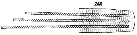
図14に図解されるように、ステップ204において、MHFCは組立体240を形成するために、その前端部に始まってシングルコアファイバのまわりに縮径される。
As illustrated in FIG. 14, in step 204, the MHFC is reduced in diameter around a single core fiber starting at its front end to form an
図15に図解されるように、ステップ205において、MHFC組立体240は、マルチコアファイバの端面に整合する直径の端面を生成するために適している先細率まで先細にされる。これを遂行するひとつの方法は、組立体の端部を加熱し、所望の先細率までそれを引き伸ばすことである。それから、先細にされた組立体の端部は、シングルコアファイバの端面を露出させ、所望の外径を達成するために、破線242で割られる。
As illustrated in FIG. 15, in
図16、および17に図解されるように、ステップ206において、溶融され、先細にされたSCFのコアがMCFの個々のコアと一直線にされて、シングルコアファイバの後端が対応する終端部に接続され、かつMHFCの前端面がMCFの端面に接続される。
As illustrated in FIGS. 16 and 17, in
4.結論
上述の説明は、当業者が本発明を実施することを可能にする詳細を含むものであるが、説明は事実上例示的なものであって、それらの多くの修正、および変形が、これらの教えの利益を得る当業者には明らかであろうことが認識されるべきである。したがって、この点で本発明はここに付属する請求の範囲によってのみ規定され、かつ請求の範囲は優先する技術によって許される限り広く解釈されるものであると意図されている。
4). CONCLUSION While the above description includes details that enable those skilled in the art to practice the invention, the description is exemplary in nature and many modifications and variations thereof will be apparent from these teachings. It should be appreciated that those skilled in the art who have the benefit of Accordingly, in this regard, the invention is defined only by the claims appended hereto and is intended to be construed as broadly as permitted by the prior art.
20、60、80 マルチコアファイバ(MCF)
22a−g コア
24 クラッド
26 六角形
28 長軸
40 結合状況
41−47 シングルコアファイバの端面
51 マルチコアファイバの端面
62、82、222 大径のファイバ
64a−g 複数の孔
84 長方形構成の孔
70 胴体
72 MHFCの後端部
74 MHFCの前端部
76、228 孔
100 MFD保持シングルモードファイバ
100’ MHFCと溶着された先細ファイバ
102/122 非先細ファイバのコア
103/123 非先細ファイバの第一の導波路
104/124 非先細ファイバの台座
105/125 非先細ファイバの第二の導波路
106/126 非先細ファイバの内側クラッド
108/128 非先細ファイバの外側クラッド
110’、130’ MHFCの胴体
120、120’ 非先細、先細ファイバの屈折率プロファイル
140 台座
102’/122’、104’/124’、106’/126’、108’/128’
先細ファイバのコア、台座、内側クラッド、外側クラッド
220 マルチホールファイバカプラ(MHFC)
224 後端部
226 前端部
230 シングルコアファイバ
240 組立体
242 破線
20, 60, 80 Multi-core fiber (MCF)
22a-
Tapered fiber core, pedestal, inner cladding,
224
Claims (12)
(a)前記複数のシングルコア光ファイバに、末端とリード端とをそれぞれが有する複数のシングルコアファイバを接続するステップであって、前記複数のシングルコアファイバの前記末端のそれぞれが、前記複数のシングルコア光ファイバの前記終端部のそれぞれに対応しており、前記複数のシングルコアファイバのそれぞれは、所与の先細率において実質的に一定のモードフィールド直径を保持するように構成されている、ステップと、
(b)前記複数のシングルコアファイバの前記リード端を、後端部、前端部、およびそれらの間に延びる複数の孔を備えた胴体を含むマルチホールファイバカプラの前記複数の孔に前記後端部側からそれぞれ挿入し、前記複数のシングルコアファイバを組立体に組み立てるステップと、
(c)前記マルチコアファイバの外径に相当する外径を有する前端面を形成するように、前記複数のシングルコアファイバを挿入した前記胴体の前記前端部を先細にするステップであって、前記複数のシングルコアファイバのコアは、前記マルチコアファイバのコアの構成に整合する構成に配列されている、ステップとを含み、
それによって、前記マルチコアファイバの前記コアと前記シングルコアファイバの前記コアとの間を搬送される光のモードフィールド直径を保持しつつ、前記マルチコアファイバを前記組立体の前記前端面に接続可能にする、方法。 Connecting each of a plurality of single-core optical fiber terminations to a corresponding separate core of a multi-core fiber having an outer diameter substantially equal to the outer diameter of the single-core fiber, comprising:
(A) a plurality of single-core optical fiber, comprising the steps of: connecting a plurality of single-core fiber having each end and the lead ends, each of said ends of said plurality of single-core fiber, said plurality of It corresponds to each of the end portions of the single-core optical fibers, each of said plurality of single-core fiber, and is configured to maintain a substantially constant mode field diameter at a given tapered rate, Steps,
(B) the lead end of the previous SL plurality of single-core fiber, the rear end, a front end, and the rear to the plurality of holes of the multi-hole fiber coupler comprising fuselage having a plurality of holes extending therebetween Inserting each from the end side, and assembling the plurality of single core fibers into an assembly;
(C) corresponds to the outer diameter of the multi-core fiber so as to form a front end surface with an outer diameter, comprising the steps of tapering the front end of the body which is inserted a plurality of single-core fiber, said plurality The core of the single-core fiber is arranged in a configuration that matches the configuration of the core of the multi-core fiber,
Thereby, the multi-core fiber can be connected to the front end face of the assembly while maintaining a mode field diameter of light carried between the core of the multi-core fiber and the core of the single-core fiber. ,Method.
前記方法は、
前記胴体の前記後端部の前記複数の孔のそれぞれに前記シングルコアファイバの前記リード端を挿入するステップと、
前記組立体を形成するために、挿入された前記シングルコアファイバの周りの前記胴体を縮径するステップと、
前記複数のシングルコアファイバを挿入した前記胴体の前記前端部を先細にし、前記前端面を形成するステップであって、前記複数のシングルコアファイバの前記コアが、前記マルチコアファイバの前記コアの構成に整合する構成に配列される、ステップと、をさらに含む、請求項1に記載の方法。 Before SL plurality of holes, is sized to receive closely the single-core fiber at said rear end of said body, said plurality of holes has a configuration that matches the configuration of the core of said multicore fiber And
The method
And inserting the lead end of the single-core fiber to each of the plurality of holes of the rear end portion of the body,
Reducing the diameter of the body around the inserted single core fiber to form the assembly; and
Tapering the front end portion of the body into which the plurality of single core fibers are inserted to form the front end surface , wherein the core of the plurality of single core fibers has the configuration of the core of the multicore fiber. The method of claim 1, further comprising: arranging in a matching configuration.
前記コア、前記台座、および前記クラッドのそれぞれが、前記コアと前記台座との間の内側導波路、および前記台座と前記クラッドの間の外側導波路を生成するように構成される屈折率を有し、
前記コア、前記台座、および前記クラッドは、前記前端部および前記後端部において前記モードフィールド直径が実質的に同じになるように構成されている、請求項1に記載の方法。 The single core fiber comprises a plurality of concentric regions defined by respective refractive indices including the core, a pedestal surrounding the core, and a clad surrounding the pedestal;
Each of the core, the pedestal, and the cladding has a refractive index configured to create an inner waveguide between the core and the pedestal and an outer waveguide between the pedestal and the cladding. And
The core, the pedestal, and the cladding, the mode field diameter at the front SL front and the rear end portion is configured to be substantially the same method as claimed in claim 1.
末端とリード端とをそれぞれが有する複数のシングルコアファイバを備え、前記複数のシングルコアファイバの前記末端のそれぞれが、前記複数のシングルコア光ファイバの前記終端部のそれぞれに対応しており、前記複数のシングルコアファイバのそれぞれは、所与の先細率において実質的に一定のモードフィールド直径を保持するように構成され、
後端部および前端部を有する胴体を備えるカプラを備え、前記カプラは、前記マルチコアファイバの外径に相当する外径を有する前端面を形成するように先細りにされ、組立体を形成するために前記複数のシングルコアファイバの前記リード端が挿入される複数の孔が設けられたマルチホールファイバカプラであり、前記シングルコアファイバのコアが前記マルチコアファイバの前記コアの構成と整合する構成に配列されており、
それによって、前記マルチコアファイバの前記コアと前記シングルコアファイバの前記コアとの間を搬送される光のモードフィールド直径を保持しつつ、前記マルチコアファイバを前記組立体の前記前端面に接続可能にする、結合組立体。 A coupling assembly connecting each of the terminations of the plurality of single core optical fibers to a corresponding separate core of the multicore fiber having an outer diameter substantially equal to the outer diameter of the single core fiber,
A plurality of single-core fibers each having a terminal end and a lead end, each of the terminal ends of the plurality of single-core fibers corresponds to each of the terminal portions of the plurality of single-core optical fibers, Each of the plurality of single core fibers is configured to maintain a substantially constant mode field diameter at a given taper;
A coupler comprising a body having a rear end and a front end, wherein the coupler is tapered to form a front end surface having an outer diameter corresponding to the outer diameter of the multi-core fiber to form an assembly; wherein a plurality of multi-hole fiber coupler in which a plurality of holes are provided for the lead end of the single-core fiber is inserted, are arranged in a configuration in which the core of the single core fiber is aligned with structure of the core of said multicore fiber And
Thereby, the multi-core fiber can be connected to the front end face of the assembly while maintaining a mode field diameter of light carried between the core of the multi-core fiber and the core of the single-core fiber. , Combined assembly.
前記カプラおよびその中に結合された前記複数のシングルコアファイバは、先細にされており、前記複数のシングルコアファイバの前記コアと前記マルチコアファイバの前記コアとが一直線をなす端面で終端されている、請求項6に記載の結合組立体。 The plurality of single-core fibers are coupled to the plurality of holes extending between the rear end portion and the front end portion of the coupler, and the plurality of holes match a configuration of the core of the multi-core fiber. Have
The coupler and the plurality of single-core fibers coupled therein are tapered, and the cores of the plurality of single-core fibers and the cores of the multi-core fibers are terminated at a straight end surface. A coupling assembly according to claim 6.
前記コア、前記台座、および前記クラッドのそれぞれが、前記コアと前記台座との間の内側導波路および前記台座と前記クラッドの間の外側導波路を生成するように構成された屈折率を有し、
前記シングルコアファイバが先細にされて前記内側導波路および前記外側導波路の直径のそれぞれが変化したときに実質的に一定のモードフィールド直径が保持されるように前記コア、前記台座、および前記クラッドが構成されている、請求項6に記載の結合組立体。 The single-core fiber comprises a plurality of concentric regions including the core, a pedestal surrounding the core, and a clad surrounding the pedestal,
Each of the core, the pedestal, and the cladding has a refractive index configured to produce an inner waveguide between the core and the pedestal and an outer waveguide between the pedestal and the cladding. ,
The core, the pedestal, and the cladding so that a substantially constant mode field diameter is maintained when the single core fiber is tapered to change the diameter of each of the inner and outer waveguides. The coupling assembly according to claim 6, wherein
前記コア、前記台座、および前記クラッドのそれぞれが、前記コアと前記台座との間の内側導波路および前記台座と前記クラッドの間の外側導波路を生成するように構成された屈折率を有し、
前記シングルコアファイバが先細にされて前記内側導波路および前記外側導波路の直径のそれぞれが変化したときに、前記マルチコアファイバのモードフィールド直径と実質的に整合するモードフィールド直径となるように前記コア、前記台座、および前記クラッドが構成されている、請求項8に記載の結合組立体。 The single-core fiber comprises a plurality of concentric regions including the core, a pedestal surrounding the core, and a clad surrounding the pedestal,
Each of the core, the pedestal, and the cladding has a refractive index configured to produce an inner waveguide between the core and the pedestal and an outer waveguide between the pedestal and the cladding. ,
When the single core fiber is tapered and each of the inner and outer waveguide diameters changes, the core has a mode field diameter that substantially matches the mode field diameter of the multi-core fiber. The coupling assembly of claim 8, wherein the pedestal and the cladding are configured.
前記シングルコアファイバの前記コア間のクロストークを防止するために、前記外側クラッド領域が前記内側クラッド領域の屈折率よりも低い屈折率を備えるように構成されている、請求項9に記載の結合組立体。 The cladding of the single-core fiber comprises an inner cladding region and an outer cladding region;
The coupling of claim 9, wherein the outer cladding region is configured to have a refractive index lower than that of the inner cladding region to prevent crosstalk between the cores of the single core fiber. Assembly.
後端部、前端部、およびそれらの間に延びる複数の孔を備える胴体を備え、前記複数の孔が対応するシングルコアファイバを密接して受け入れる寸法とされ、前記複数の孔は、ファイバの中心に位置する第1のコアと、前記第1のコアを取り囲む六角形として配置された6つのコアとを有する7コアマルチコアファイバの個々のコアの構成に相似的に整合する構成を有し、
前記カプラの前記胴体の前記前端部は、あらかじめ先細にされ、前記複数の孔は、前記シングルコアファイバの直径よりも小さい直径にまで先細にされており、前記シングルコアファイバが前記カプラの前記胴体の前記後端部にある前記複数の孔に挿入されたとき、前記複数の孔を通るその進行が途中で止められるように構成されている、カプラ。 A coupler,
A fuselage having a rear end, a front end, and a plurality of holes extending therebetween, the plurality of holes being sized to closely receive a corresponding single core fiber, the plurality of holes being at the center of the fiber a first core positioned, the construction of similar-aligned to the configuration of the individual cores of 7 core multicore fiber having six cores arranged as a hexagon surrounding the first core possess a,
The front end of the body of the coupler is tapered in advance, the plurality of holes are tapered to a diameter smaller than the diameter of the single core fiber, and the single core fiber is the body of the coupler. A coupler configured to stop its progress through the plurality of holes when it is inserted into the plurality of holes at the rear end portion of the coupler.
コア、前記コアを取り囲む台座、前記台座を取り囲む内側クラッド領域、および前記内側クラッド領域を取り囲む外側クラッドを含む、それぞれの屈折率を有する複数の同心領域を備え、
前記複数の同心領域は、前記コアと前記台座との間の第一の導波路、および前記台座と前記内側クラッドの間の第二の導波路を生成するように構成され、
前記シングルコアファイバが先細にされて前記内側導波路および前記外側導波路の直径のそれぞれが変化したときに実質的に一定のモードフィールド直径が保持されるように前記コア、前記台座、および前記クラッドが構成されており、
クロストークが複数の同様のファイバを備える先細にされた組立体の中で低減されるように、前記外側のクラッドが落ち込んだ屈折率を有する、シングルコアファイバ。 Single core fiber,
A plurality of concentric regions each having a refractive index including a core, a pedestal surrounding the core, an inner cladding region surrounding the pedestal, and an outer cladding surrounding the inner cladding region;
The plurality of concentric regions are configured to generate a first waveguide between the core and the pedestal, and a second waveguide between the pedestal and the inner cladding;
The core, the pedestal, and the cladding so that a substantially constant mode field diameter is maintained when the single core fiber is tapered to change the diameter of each of the inner and outer waveguides. Is configured,
A single core fiber in which the outer cladding has a depressed index of refraction so that crosstalk is reduced in a tapered assembly comprising a plurality of similar fibers.
Applications Claiming Priority (3)
| Application Number | Priority Date | Filing Date | Title |
|---|---|---|---|
| US31418210P | 2010-03-16 | 2010-03-16 | |
| US61/314,182 | 2010-03-16 | ||
| PCT/US2011/028692 WO2011116109A1 (en) | 2010-03-16 | 2011-03-16 | Techniques and devices for low-loss, modefield matched coupling to a multicore fiber |
Publications (3)
| Publication Number | Publication Date |
|---|---|
| JP2013522677A JP2013522677A (en) | 2013-06-13 |
| JP2013522677A5 JP2013522677A5 (en) | 2014-06-19 |
| JP5782104B2 true JP5782104B2 (en) | 2015-09-24 |
Family
ID=44649587
Family Applications (1)
| Application Number | Title | Priority Date | Filing Date |
|---|---|---|---|
| JP2013500185A Active JP5782104B2 (en) | 2010-03-16 | 2011-03-16 | Method and apparatus for low loss, mode field matched coupling to multi-core fiber |
Country Status (4)
| Country | Link |
|---|---|
| US (1) | US20110280517A1 (en) |
| EP (1) | EP2548057B1 (en) |
| JP (1) | JP5782104B2 (en) |
| WO (1) | WO2011116109A1 (en) |
Cited By (1)
| Publication number | Priority date | Publication date | Assignee | Title |
|---|---|---|---|---|
| WO2019003466A1 (en) | 2017-06-29 | 2019-01-03 | 株式会社フジクラ | Method for manufacturing optical device |
Families Citing this family (35)
| Publication number | Priority date | Publication date | Assignee | Title |
|---|---|---|---|---|
| US9857536B2 (en) * | 2008-07-14 | 2018-01-02 | Chiral Photonics, Inc. | Optical component assembly for use with an optical device |
| EP2548056B1 (en) * | 2010-03-16 | 2021-05-05 | OFS Fitel, LLC | Multicore transmission and amplifier fibers and schemes for launching pump light to amplifier cores |
| US8903211B2 (en) * | 2011-03-16 | 2014-12-02 | Ofs Fitel, Llc | Pump-combining systems and techniques for multicore fiber transmissions |
| EP2722943A4 (en) * | 2011-06-16 | 2014-11-05 | Furukawa Electric Co Ltd | Multicore amplifying optical fiber |
| US9348090B2 (en) * | 2012-02-27 | 2016-05-24 | Sumitomo Electric Industries, Ltd. | Optical coupling element and manufacturing method |
| US8515220B1 (en) | 2012-04-12 | 2013-08-20 | Raytheon Company | Optical fiber coupler for coupling signal beams into a non-circularly shaped optical beam |
| DE102012209630A1 (en) * | 2012-06-08 | 2013-12-12 | Jenoptik Laser Gmbh | fiber coupler |
| JP5990419B2 (en) * | 2012-07-09 | 2016-09-14 | 株式会社フジクラ | Optical input / output device |
| US20140233893A1 (en) * | 2012-07-31 | 2014-08-21 | Commscope, Inc. Of North Carolina | Backwards compatible multi-core fiber optic cable |
| JPWO2014034726A1 (en) * | 2012-08-29 | 2016-08-08 | コニカミノルタ株式会社 | Optical fiber coupling member and method of manufacturing optical fiber coupling member |
| CN102916747A (en) * | 2012-10-25 | 2013-02-06 | 华中科技大学 | Optical distribution network and passive optical network based on multi-core fiber |
| US9513189B2 (en) * | 2012-11-08 | 2016-12-06 | Ofs Fitel, Llc | Device and method to measure the DMD and other parameters of a multicore optical fiber |
| EP2944989A4 (en) * | 2013-01-10 | 2016-09-07 | Sumitomo Electric Industries | Optical component and optical communication system |
| US10101536B2 (en) * | 2013-06-14 | 2018-10-16 | Chiral Photonics, Inc. | Multichannel optical coupler array |
| US11966091B2 (en) * | 2013-06-14 | 2024-04-23 | Chiral Photonics, Inc. | Multichannel optical coupler array |
| US10126494B2 (en) * | 2013-06-14 | 2018-11-13 | Chiral Photonics, Inc. | Configurable polarization mode coupler |
| US9817191B2 (en) * | 2013-06-14 | 2017-11-14 | Chiral Photonics, Inc. | Multichannel optical coupler array |
| US11156781B2 (en) * | 2013-06-14 | 2021-10-26 | Chiral Photonics, Inc. | Passive aligning optical coupler array |
| US10564348B2 (en) * | 2013-06-14 | 2020-02-18 | Chiral Photonics, Inc. | Passive aligning optical coupler array |
| US10914891B2 (en) * | 2013-06-14 | 2021-02-09 | Chiral Photonics, Inc. | Multichannel optical coupler |
| US10838155B2 (en) | 2013-06-14 | 2020-11-17 | Chiral Photonics, Inc. | Multichannel optical coupler |
| WO2015018947A1 (en) | 2013-08-09 | 2015-02-12 | Technical University Of Denmark | Wireless distributed antenna mimo |
| JP5572748B1 (en) * | 2013-08-20 | 2014-08-13 | 湖北工業株式会社 | OPTICAL CONNECTION COMPONENT, ITS MANUFACTURING METHOD, AND OPTICAL CONNECTION COMPONENT MANUFACTURING MOLD CONTAINER |
| US9537282B2 (en) * | 2013-09-20 | 2017-01-03 | Alcatel Lucent | System and method for a multi-mode pump in an optical amplifier |
| US20150085352A1 (en) * | 2013-09-20 | 2015-03-26 | Alcatel-Lucent Usa Inc. | Optical amplifier for space-division multiplexing |
| JP5986594B2 (en) * | 2014-02-14 | 2016-09-06 | 株式会社フジクラ | Optical device |
| JP6181682B2 (en) | 2015-02-20 | 2017-08-16 | 株式会社フジクラ | Optical device |
| JP2018055043A (en) * | 2016-09-30 | 2018-04-05 | 株式会社アマダホールディングス | Optical fiber combiner and laser device |
| WO2019016797A1 (en) | 2017-07-17 | 2019-01-24 | Z Square Ltd. | Enhancing imaging by multicore fiber endoscopes |
| GB2565128A (en) * | 2017-08-03 | 2019-02-06 | Fujikura Ltd | Fan-in/Fan-out device |
| JPWO2021112016A1 (en) * | 2019-12-03 | 2021-06-10 | ||
| US11630274B2 (en) | 2020-04-01 | 2023-04-18 | Mellanox Technologies, Ltd. | High-density optical communications using multi-core fiber |
| US11561352B2 (en) | 2020-04-01 | 2023-01-24 | Mellanox Technologies, Ltd. | High density optical I/O inside a data center switch using multi-core fibers |
| US11916598B2 (en) * | 2020-04-13 | 2024-02-27 | Avicenatech Corp. | Parallel optical communication channels using microLEDs |
| US11378765B2 (en) * | 2020-05-25 | 2022-07-05 | Mellanox Technologies, Ltd. | Intra data center and inter data center links using dual-wavelength multimode/singlemode multi-core fiber |
Family Cites Families (24)
| Publication number | Priority date | Publication date | Assignee | Title |
|---|---|---|---|---|
| JPS6011804A (en) * | 1983-06-30 | 1985-01-22 | Sumitomo Electric Ind Ltd | Branching device of optical fiber |
| JPS6080806A (en) * | 1983-10-11 | 1985-05-08 | Sumitomo Electric Ind Ltd | Optical branching filter and its production |
| JPS6247604A (en) * | 1985-08-27 | 1987-03-02 | Furukawa Electric Co Ltd:The | Terminal part for multicore fiber |
| US5748820A (en) * | 1994-03-24 | 1998-05-05 | France Telecom | Component for connection to a multi-core fiber, and a method of manufacture |
| FR2747800A1 (en) | 1996-04-19 | 1997-10-24 | Alcatel Cable | Junction unit for linking optical fibre cores within alignment sleeve |
| US5864644A (en) | 1997-07-21 | 1999-01-26 | Lucent Technologies Inc. | Tapered fiber bundles for coupling light into and out of cladding-pumped fiber devices |
| EP1108234A4 (en) * | 1998-06-29 | 2005-06-15 | Corning Inc | Monolithic coaxial device |
| US7221840B2 (en) * | 2002-03-15 | 2007-05-22 | Crystal Fibre A/S | Microstructured optical fibre with cladding recess, a method of its production, and apparatus comprising same |
| US7046890B2 (en) * | 2003-09-30 | 2006-05-16 | Corning Incorporated | Optical fiber with low taper induced loss |
| US7492998B2 (en) * | 2004-08-31 | 2009-02-17 | Corning Incorporated | Fiber bundles and methods of making fiber bundles |
| US7236671B2 (en) * | 2005-05-10 | 2007-06-26 | Corning Incorporated | Fiber bundles and methods of making fiber bundles |
| US7409128B2 (en) * | 2005-06-29 | 2008-08-05 | Lucent Technologies Inc. | Pumping arrangement for fiber amplifiers with reduced reflective feedback |
| CA2523930A1 (en) * | 2005-10-19 | 2007-04-19 | Itf Technologies Optiques Inc./Itf Optical Technologies Inc. | Method of making fiber optic couplers with precise positioning of fibers |
| CN101583891A (en) * | 2005-11-23 | 2009-11-18 | 康宁股份有限公司 | Low attenuation non-zero dispersion shifted optical fiber |
| JP5089950B2 (en) * | 2006-05-30 | 2012-12-05 | 株式会社フジクラ | Multi-port coupler, optical amplifier and fiber laser |
| US8102885B2 (en) * | 2007-05-08 | 2012-01-24 | The Arizona Board Of Regents On Behalf Of The University Of Arizona | All-fiber mode selection technique for multicore fiber laser devices |
| WO2009077637A1 (en) * | 2007-12-14 | 2009-06-25 | Corelase Oy | Method and device relating to optical fibers |
| US20130216184A1 (en) * | 2008-07-14 | 2013-08-22 | Victor Il'ich Kopp | Configurable pitch reducing optical fiber array |
| WO2010120958A1 (en) * | 2009-04-14 | 2010-10-21 | Ofs Fitel, Llc | Fiber based laser combiners |
| JP2010286661A (en) * | 2009-06-11 | 2010-12-24 | Sumitomo Electric Ind Ltd | Fiber array and optical connector including the same |
| WO2011071750A1 (en) * | 2009-12-02 | 2011-06-16 | Ofs Fitel Llc. A Delaware Limited Liability Company | Techniques for manipulating crosstalk in multicore fibers |
| WO2011112846A1 (en) * | 2010-03-10 | 2011-09-15 | Ofs Fitel Llc. A Delaware Limited Liability Company | Multicore fibers and associated structures and techniques |
| EP2548056B1 (en) * | 2010-03-16 | 2021-05-05 | OFS Fitel, LLC | Multicore transmission and amplifier fibers and schemes for launching pump light to amplifier cores |
| US8515220B1 (en) * | 2012-04-12 | 2013-08-20 | Raytheon Company | Optical fiber coupler for coupling signal beams into a non-circularly shaped optical beam |
-
2011
- 2011-03-16 EP EP11756943.4A patent/EP2548057B1/en active Active
- 2011-03-16 US US13/049,597 patent/US20110280517A1/en not_active Abandoned
- 2011-03-16 JP JP2013500185A patent/JP5782104B2/en active Active
- 2011-03-16 WO PCT/US2011/028692 patent/WO2011116109A1/en active Application Filing
Cited By (2)
| Publication number | Priority date | Publication date | Assignee | Title |
|---|---|---|---|---|
| WO2019003466A1 (en) | 2017-06-29 | 2019-01-03 | 株式会社フジクラ | Method for manufacturing optical device |
| US11644632B2 (en) | 2017-06-29 | 2023-05-09 | Fujikura Ltd. | Method for manufacturing optical device |
Also Published As
| Publication number | Publication date |
|---|---|
| EP2548057B1 (en) | 2019-11-27 |
| WO2011116109A1 (en) | 2011-09-22 |
| JP2013522677A (en) | 2013-06-13 |
| EP2548057A4 (en) | 2017-12-13 |
| US20110280517A1 (en) | 2011-11-17 |
| EP2548057A1 (en) | 2013-01-23 |
Similar Documents
| Publication | Publication Date | Title |
|---|---|---|
| JP5782104B2 (en) | Method and apparatus for low loss, mode field matched coupling to multi-core fiber | |
| US10761271B2 (en) | Polarization maintaining optical fiber array | |
| US6823117B2 (en) | Mode multiplexing optical coupling device | |
| US9885825B2 (en) | Pitch reducing optical fiber array and multicore fiber comprising at least one chiral fiber grating | |
| US9810845B2 (en) | Flexible optical fiber array | |
| CN101405635B (en) | Multimode fiber outer cladding coupler for multi-clad fibers | |
| US3933455A (en) | Method for joining optical fibre bundles | |
| JP5768090B2 (en) | Fan-in / fan-out device for multi-core fiber | |
| CA2523930A1 (en) | Method of making fiber optic couplers with precise positioning of fibers | |
| JP2013522677A5 (en) | ||
| EP0628839B1 (en) | Low loss coupler | |
| JP5910123B2 (en) | Manufacturing method of multi-core optical fiber tape | |
| US20030180016A1 (en) | Method of splicing optical fibers and multi-fiber component | |
| JP2015152871A (en) | Optical fiber device | |
| US20100189391A1 (en) | Multimode optical combiner and process for producing the same | |
| JP4116479B2 (en) | Tapered photonic crystal fiber, manufacturing method thereof, and connection method of photonic crystal fiber | |
| WO2020209364A1 (en) | Optical connector and method for manufacturing optical connector | |
| JPS63129307A (en) | Star coupler and its manufacture | |
| US11267210B2 (en) | Production of a fiber coupler | |
| US20230176300A1 (en) | Optical fiber bundle structure, optical connection structure, and method of manufacturing optical fiber bundle | |
| CN115128740B (en) | Signal beam combiner, laser and manufacturing method of signal beam combiner | |
| US20230138454A1 (en) | Multicore fiber stubs, multicore fan-in, fan-out devices, and methods of fabricating the same | |
| CN117538980A (en) | Preparation method of multi-core fiber coupler adopting large-core graded-index fiber | |
| CN117492139A (en) | 1X 3 light beam splitter and processing method thereof | |
| JP2000206361A (en) | Optical fiber type multi-branch coupler, and manufacture thereof |
Legal Events
| Date | Code | Title | Description |
|---|---|---|---|
| A977 | Report on retrieval |
Free format text: JAPANESE INTERMEDIATE CODE: A971007 Effective date: 20140114 |
|
| A131 | Notification of reasons for refusal |
Free format text: JAPANESE INTERMEDIATE CODE: A131 Effective date: 20140128 |
|
| A524 | Written submission of copy of amendment under article 19 pct |
Free format text: JAPANESE INTERMEDIATE CODE: A524 Effective date: 20140428 |
|
| A131 | Notification of reasons for refusal |
Free format text: JAPANESE INTERMEDIATE CODE: A131 Effective date: 20141222 |
|
| A601 | Written request for extension of time |
Free format text: JAPANESE INTERMEDIATE CODE: A601 Effective date: 20150323 |
|
| A521 | Request for written amendment filed |
Free format text: JAPANESE INTERMEDIATE CODE: A523 Effective date: 20150602 |
|
| TRDD | Decision of grant or rejection written | ||
| A01 | Written decision to grant a patent or to grant a registration (utility model) |
Free format text: JAPANESE INTERMEDIATE CODE: A01 Effective date: 20150618 |
|
| A61 | First payment of annual fees (during grant procedure) |
Free format text: JAPANESE INTERMEDIATE CODE: A61 Effective date: 20150716 |
|
| R150 | Certificate of patent or registration of utility model |
Ref document number: 5782104 Country of ref document: JP Free format text: JAPANESE INTERMEDIATE CODE: R150 |
|
| R250 | Receipt of annual fees |
Free format text: JAPANESE INTERMEDIATE CODE: R250 |
|
| R250 | Receipt of annual fees |
Free format text: JAPANESE INTERMEDIATE CODE: R250 |
|
| R250 | Receipt of annual fees |
Free format text: JAPANESE INTERMEDIATE CODE: R250 |
|
| R250 | Receipt of annual fees |
Free format text: JAPANESE INTERMEDIATE CODE: R250 |
|
| R250 | Receipt of annual fees |
Free format text: JAPANESE INTERMEDIATE CODE: R250 |
|
| R250 | Receipt of annual fees |
Free format text: JAPANESE INTERMEDIATE CODE: R250 |