JP5779989B2 - Thread cutting method - Google Patents
Thread cutting method Download PDFInfo
- Publication number
- JP5779989B2 JP5779989B2 JP2011121310A JP2011121310A JP5779989B2 JP 5779989 B2 JP5779989 B2 JP 5779989B2 JP 2011121310 A JP2011121310 A JP 2011121310A JP 2011121310 A JP2011121310 A JP 2011121310A JP 5779989 B2 JP5779989 B2 JP 5779989B2
- Authority
- JP
- Japan
- Prior art keywords
- screw
- thread
- chaser
- blade type
- thread cutting
- Prior art date
- Legal status (The legal status is an assumption and is not a legal conclusion. Google has not performed a legal analysis and makes no representation as to the accuracy of the status listed.)
- Active
Links
Images


Description
本発明は、ねじ切削方法に関する。このねじ切削方法は、一般に油井やガス井の探査や生産に使用されるチュービングおよびケーシングを包含する油井管、すなわちOCTG(oil country tubular goods)、ライザー管、ならびにラインパイプなどの鋼管の接続に用いるのに好適な、シール性と耐圧縮性に優れた鋼管用ねじ継手を製作する際のねじ切り加工に好ましく用いうる。 The present invention relates to a thread cutting method. This thread cutting method is generally used for connecting oil well pipes including tubing and casings used for exploration and production of oil wells and gas wells, that is, OCTG (oil country tubular goods), riser pipes, and steel pipes such as line pipes. Therefore, it can be preferably used for threading when producing a threaded joint for steel pipes excellent in sealing performance and compression resistance.
前記ねじ継手は、油井管など産油産業設備に使用される鋼管の接続に広く使用されている。オイルやガスの探索や生産に使用される鋼管の接続には、従来API(米国石油協会)規格に規定された標準的なねじ継手が使用されてきた。しかし、近年、原油や天然ガスの井戸は深井戸化が進み、垂直井から水平井や傾斜井が増加していることから、掘削・生産環境は苛酷化している。また、海洋や極地など劣悪な環境での井戸の開発が増加していることなどから、耐圧縮性能、耐曲げ性能、外圧シール性能(耐外圧性能)など、ねじ継手への要求性能は多様化している。そのため、プレミアムジョイントと呼ばれる高性能の特殊ねじ継手を使用することが増加している。 The threaded joint is widely used for connecting steel pipes used in oil industry equipment such as oil well pipes. Conventionally, standard threaded joints defined in API (American Petroleum Institute) standards have been used to connect steel pipes used in the search and production of oil and gas. However, in recent years, wells for crude oil and natural gas have been deepened, and horizontal wells and inclined wells have increased from vertical wells, and the drilling and production environment has become severe. In addition, the demand for screw joints such as compression resistance, bending resistance, and external pressure seal performance (external pressure resistance) has diversified due to the increased development of wells in poor environments such as the ocean and polar regions. ing. Therefore, the use of high-performance special threaded joints called premium joints is increasing.
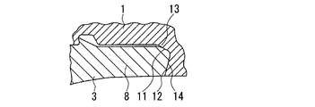
図2〜図4は、油井管用プレミアムジョイントの模式的説明図であり、これらは、円管のねじ継手の縦断面図である。ねじ継手は、ピン部材3とこれに対応するボックス部材1とを備えており、ピン部材3(ピン3)は、その外面に雄ねじ7と、ピン3の先端側に雄ねじ7に隣接して設けられたノーズ部8(ピンノーズ8)と呼ばれるねじ無し部とを有する。ノーズ部8は、その外周面にシール部11を、その端面にはトルクショルダ部12を有する。相対するボックス部材1は、その内面に、それぞれピン3の雄ねじ7、シール部11、およびショルダ部12と螺合するか、または接触することができる部分である、雌ねじ5、シール部13、および、ショルダ部14を有している。
FIGS. 2-4 is typical explanatory drawing of the premium joint for oil well pipes, These are the longitudinal cross-sectional views of the threaded joint of a circular pipe. The threaded joint includes a
なお、ねじ形状を記述する量として、図5に示すロードフランク角度β(雄ねじのねじ山後面すなわちロードフランク面18が継手軸への垂線に対してなす角度β)、スタブフランク角度γ(雄ねじのねじ山前面すなわちスタブフランク面19が継手軸への垂線に対してなす角度γ)、ねじ隙間G(雄ねじのねじ山7aとこれに噛み合う雌ねじのねじ溝5aとの隙間G)が用いられる。なお角度β、γは、図示のように、面18,19のそれぞれにおいて頂部が底部からみてこれら両面間の中心側にくる場合を正、その逆側にくる場合を負とされる。
Note that the load flank angle β shown in FIG. 5 (the angle β formed by the load flank surface of the male screw, that is, the
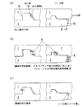
ねじ隙間Gの役割について、図6を用いて説明する。ねじ締付け時には、雄ねじのロードフランク面18が雌ねじの対応面で押されることでピン3先端がボックス1にメタル接触してシール部が形成される(図6(a))。一方、シール部のシール効果を高めるために管軸方向の圧縮力を加えながら締付けを行う場合(図6(b))も多々ある。この場合、雄ねじのスタブフランク面が雌ねじの対応面と押し合うことで、シール部及びショルダ部における接触面圧を軽減し、シール部及びショルダ部が過大に塑性変形するのを防止する。すなわち耐圧縮性能を向上させる。この効果を十分なものとするにはねじ隙間Gを小さくする必要があるが、小さくし過ぎると雄ねじのスタブフランク面19と雌ねじの対応面との間でゴーリング(焼付き、むしれ)が起り易くなる。すなわち耐ゴーリング性能が低下する。また、ねじ締付け後のねじ継手には管軸方向の引張力が加わる場合(図6(c))も多々ある。この場合、雄ねじのロードフランク面が雌ねじの対応面と押し合うことでシール部の接触面圧低下によるシール性低下を防止する。すなわち耐引張性能を向上させる。この効果を十分なものとするにはねじ隙間Gを小さくする必要があるが、小さくし過ぎると雄ねじのロードフランク面と雌ねじの対応面との間でゴーリング(焼付き、むしれ)が起り易くなる。すなわち耐ゴーリング性能が低下する。
The role of the screw gap G will be described with reference to FIG. At the time of screw tightening, the
このように、ねじ隙間Gは、ねじ継手の耐圧縮乃至引張性能、耐ゴーリング性能への主要な影響因子であって、適正範囲に調整する必要があるため、例えば特許文献1では、ねじ隙間Gの好適範囲を0.05〜0.25mmとしている。
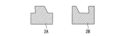
上記ねじ継手の製作時には、ピン部材用とした管体の外周面とボックス部材用とした管体の内周面とに対してそれぞれねじ切削(ねじ切り)加工が施される。このねじ切削方法として、例えば特許文献1に記載されるように、通常、チェザーと呼ばれるねじ切削用刃物を管体の被切削面に押し当て、管体を回転させつつ管軸方向に前後進させる方法が採用される。このとき1つのねじ切削工程が必要に応じて複数の切削深さ段階に分割され、その相異なる切削深さ段階に応じてチェザーを移動し、切削する。チェザーの送りピッチ(管体に対するチェザーの1周回あたりの管軸方向移動量)は、ねじの規格ピッチに応じた一定の標準に設定される。ねじ隙間Gはねじの規格形状の許容範囲内で刃幅を変更することで調整される。また、チェザーには、図7に示すように凸刃型2Aと凹刃型2Bとがあり、通常、1つのねじ継手のピン用、ボックス用の両管体をねじ切り加工する際には同型のチェザー(凸刃型、凹刃型のいずれか一方のみ)が使用される。
As described above, the screw gap G is a main influential factor on the compression resistance or tensile performance and galling resistance performance of the threaded joint, and needs to be adjusted to an appropriate range. The preferred range of 0.05 to 0.25 mm.
At the time of manufacturing the threaded joint, thread cutting (thread cutting) is performed on the outer peripheral surface of the tubular body for the pin member and the inner peripheral surface of the tubular body for the box member. As this thread cutting method, as described in, for example,
上述のとおり、従来のねじ切削加工では、1つのねじ継手のピン用、ボックス用の両管体をねじ切り加工する際には同型のチェザー(凸刃型、凹刃型のいずれか一方のみ)が使用される。そのため、チェザー送りピッチPを変えるとねじ隙間Gが変化する(図8参照)。したがって、ねじピッチの相異なるねじ継手のねじ隙間を適正値に統一しようとする場合、チェザー送りピッチの変更に付随するねじ隙間の変化を補償して、ねじ隙間を一定値に統一するためには、相異なるねじピッチごとに相異なる刃形状のチェザーを準備する必要があり、チェザー準備工数が嵩むという課題があった。 As described above, in the conventional thread cutting process, the same type of chaser (only one of the convex blade type and the concave blade type) is used when threading both the tube for the pin of the single threaded joint and the box. used. Therefore, when the chaser feed pitch P is changed, the screw gap G changes (see FIG. 8). Therefore, when trying to unify the screw gaps of screw joints with different screw pitches to an appropriate value, in order to compensate for changes in the screw gaps accompanying changes in the chaser feed pitch and to unify the screw gaps to a constant value, There is a problem in that it is necessary to prepare a different blade-shaped chaser for each different screw pitch, and the number of man-hours for preparing the chaser increases.
本発明は、前記課題を解決するためになされたものであり、その要旨は次のとおりである。
(1)鋼管用ねじ継手の素材とした雄ねじ用管体と雌ねじ用管体とに凹部1つのみの凹刃型または凸部1つのみの凸刃型からなるねじ切削用刃物であるチェザーを用いてねじ切削加工を施すにあたり、凹刃型、凸刃型のうちいずれか一方の刃型のチェザーを雄ねじ用管体に、他方の刃型のチェザーを雌ねじ用管体に、それぞれ用いることを特徴とするねじ切削方法。
The present invention has been made to solve the above-described problems, and the gist thereof is as follows.
(1) a threaded joint for steel pipes materials and to recess only one凹刃type or screw cutting tool comprising a protrusion only one convex cutting die to the tube body and internally threaded pipe body male screw was of a chaser When performing thread cutting using, use either the recessed blade type or the convex blade type of the chaser of the blade type for the male threaded tube, and the other blade type of the chaser for the female threaded tube. A thread cutting method characterized by the above.
本発明によれば、ねじピッチを変更してもねじ隙間が一定に保たれるので、従来(ねじピッチを変更するとねじ隙間が変化し、これを補償してねじ隙間を一定に保つには、チェザー刃形状を変更する必要がある)と比べて、チェザー準備工数が削減でき、ねじ継手製造コストを低減できる。 According to the present invention, since the screw gap is kept constant even if the screw pitch is changed, the conventional method (in order to compensate for this and to keep the screw gap constant by changing the screw pitch, Compared with the need to change the shape of the chaser blade), the number of man-hours for preparing the chaser can be reduced, and the manufacturing cost of the threaded joint can be reduced.
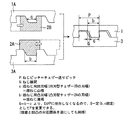
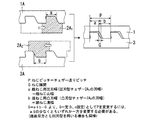
図1は本発明の実施形態の1例を示す断面図である。この実施形態では、雌ねじ用(ボックス用)管体1Aのねじ切削には凹刃型チェザー2Bを使用し、一方、雄ねじ用(ピン用)管体3Aのねじ切削には凸刃型チェザー2Aを使用している。これにより、図示のとおり、ねじ隙間Gは凹凸のチェザー刃幅のみに依存し、ねじピッチPに依存しなくなる(G=b-c)ので、ねじピッチPの変更に対して同じ刃形状のチェザーを用いてねじ隙間Gを一定とすることができる。尚、図1の例とは逆に、雄ねじ用管体に凹刃型、雌ねじ用管体に凸刃型を用いても同様である。
FIG. 1 is a cross-sectional view showing an example of an embodiment of the present invention. In this embodiment, a concave-
以下の形状のねじ切削へ適用すると良い。
ロードフランク角度が-10〜+3°、スタブフランク角度が+10〜+30°。
ねじ山底部の幅がねじ山頂部の幅よりも大きく、その比率が1.1倍以上。
ねじ山底部の幅がねじ山高さよりも大きく、その比率が1.2倍以上。
雄ねじと雌ねじのスタブ面の間隔Gが0.025〜0.150mm、特にスタブ面の間隔Gが0.100mm以下といった狭いねじの切削に適している。
It is good to apply to the following thread cutting.
The load flank angle is -10 to + 3 °, and the stub flank angle is +10 to + 30 °.
The width of the thread bottom is larger than the width of the thread top, and the ratio is 1.1 times or more.
The width of the thread bottom is larger than the thread height, and the ratio is 1.2 times or more.
It is suitable for cutting narrow threads where the gap G between the male screw and female screw is 0.025 to 0.150 mm, particularly the gap G between the stub faces is 0.100 mm or less.
油井管用ねじ継手の製作では、1つまたは切削深さに応じた複数のチェザーを用いてねじ切削が行われる。
前記油井管用ねじ継手のねじ隙間を一定としてねじピッチを5水準違えるにあたり、本発明に則り、図1の例とは逆に、雌ねじ用管体は凸刃型チェザーで、雄ねじ用管体は凹刃型チェザーで、チェザーの送りピッチを凹凸とも同じとして、継手ごとに変更して、ねじ切削を行った。このとき、準備する相異なる刃形状のチェザーの総数は、雌雄で各1個、計2個であり、以下に示す比較例に比べチェザー準備工数が大幅に削減できてねじ継手製造コストが削減できた。
(比較例)
前記油井管用ねじ継手のねじ隙間を一定としてねじピッチを5水準違えるにあたり、従来通り雌雄双方とも凸刃型チェザーでねじ切削を行った。このとき、準備する相異なる刃形状のチェザーの総数は、雌用1個×5水準=5個と、雄用1個×5水準=5個との合計10個を必要とした。
In the manufacture of a threaded joint for oil country tubular goods, thread cutting is performed using one or a plurality of chaser according to the cutting depth.
According to the present invention, in contrast to the example of FIG. 1, the female thread pipe is a convex-blade type chaser and the male thread pipe is concave. With a blade-type chaser, the feed pitch of the chaser was the same as the unevenness, and the thread cutting was performed by changing each joint. At this time, the total number of the different blade-shaped chessers to be prepared is one each for males and females, for a total of two, which makes it possible to greatly reduce the number of chesser preparation man-hours and reduce the screw joint manufacturing cost compared to the comparative example shown below. It was.
(Comparative example)
When changing the thread pitch of the oil well pipe threaded joint at a constant level by 5 levels, both males and females were thread-cut using a convex-blade type chaser. At this time, the total number of the different blade-shaped chesers to be prepared required 10 pieces of 1 for females × 5 levels = 5 and 1 for males × 5 levels = 5.
1 ボックス(ボックス部材)
1A 雌ねじ用管体(ボックス用管体)
2 チェザー(ねじ切削用刃物;2Aは凸刃型、2Bは凹刃型)
3 ピン(ピン部材)
3A 雄ねじ用管体(ピン用管体)
5 雌ねじ(雌ねじ部)
5a 雌ねじのねじ溝
7 雄ねじ(雄ねじ部)
7a 雄ねじのねじ山
8 ノーズ部(ピンノーズ)
11、13 シール部(詳しくはメタルタッチシール部)
12、14 ショルダ部(詳しくはトルクショルダ部)
18 ロードフランク面
19 スタブフランク面
1 Box (box material)
1A Female thread tube (Box tube)
2 Chezer (Thread cutting tool; 2A is a convex blade type, 2B is a concave blade type)
3 Pin (Pin material)
3A Male thread tube (Pin tube)
5 Female thread (Female thread)
5a Female thread groove
7 Male thread (Male thread)
7a Male thread thread
8 Nose (pin nose)
11, 13 Seal part (Details are metal touch seal part)
12, 14 Shoulder part (For details, torque shoulder part)
18 Road flank surface
19 Stub flank surface
Claims (1)
Priority Applications (1)
| Application Number | Priority Date | Filing Date | Title |
|---|---|---|---|
| JP2011121310A JP5779989B2 (en) | 2010-06-30 | 2011-05-31 | Thread cutting method |
Applications Claiming Priority (3)
| Application Number | Priority Date | Filing Date | Title |
|---|---|---|---|
| JP2010149282 | 2010-06-30 | ||
| JP2010149282 | 2010-06-30 | ||
| JP2011121310A JP5779989B2 (en) | 2010-06-30 | 2011-05-31 | Thread cutting method |
Publications (2)
| Publication Number | Publication Date |
|---|---|
| JP2012030348A JP2012030348A (en) | 2012-02-16 |
| JP5779989B2 true JP5779989B2 (en) | 2015-09-16 |
Family
ID=45844401
Family Applications (1)
| Application Number | Title | Priority Date | Filing Date |
|---|---|---|---|
| JP2011121310A Active JP5779989B2 (en) | 2010-06-30 | 2011-05-31 | Thread cutting method |
Country Status (1)
| Country | Link |
|---|---|
| JP (1) | JP5779989B2 (en) |
Family Cites Families (6)
| Publication number | Priority date | Publication date | Assignee | Title |
|---|---|---|---|---|
| US3994516A (en) * | 1975-03-05 | 1976-11-30 | Otis Engineering Corporation | Telescoping pipe coupling with improved pressure seal connection threads |
| US4485511A (en) * | 1982-08-11 | 1984-12-04 | Pmc Industries, Inc. | Die head with different axial tool paths |
| US4568113A (en) * | 1983-04-04 | 1986-02-04 | Awb, Inc. | Pipe connection |
| JPS60186103U (en) * | 1984-05-23 | 1985-12-10 | 宇野沢 敦夫 | Cutter for thread cutting |
| SE505157C2 (en) * | 1995-10-31 | 1997-07-07 | Seco Tools Ab | Method and cutting for threading |
| EP1020674B1 (en) * | 1998-07-31 | 2004-02-18 | JFE Steel Corporation | Oil well pipe screw joint, and threading method therefor |
-
2011
- 2011-05-31 JP JP2011121310A patent/JP5779989B2/en active Active
Also Published As
| Publication number | Publication date |
|---|---|
| JP2012030348A (en) | 2012-02-16 |
Similar Documents
| Publication | Publication Date | Title |
|---|---|---|
| JP4535064B2 (en) | Threaded joints for steel pipes | |
| AU2016340415B2 (en) | Threaded connection for steel pipe | |
| CA2931087C (en) | Threaded joint for heavy-walled oil country tubular goods | |
| WO2012002409A1 (en) | Pipe screw coupling | |
| CN202611607U (en) | Thread connector for pipe | |
| EP1529178A1 (en) | Thread design for uniform distribution of makeup forces | |
| WO2017141538A1 (en) | Threaded joint for oil well pipe | |
| JP2012031988A (en) | Screw joint for steel pipe | |
| JP5779990B2 (en) | Thread cutting method | |
| JP6103137B2 (en) | Threaded joints for pipes | |
| WO2014199619A1 (en) | Threaded joint for oil well pipe | |
| JP5779989B2 (en) | Thread cutting method | |
| JP5906588B2 (en) | Manufacturing method of threaded joint for steel pipe | |
| JP5776222B2 (en) | Threaded joints for steel pipes | |
| JP2014101983A (en) | Pipe screw joint | |
| JP5783146B2 (en) | Threaded joints for steel pipes | |
| WO2014199620A1 (en) | Threaded joint for oil well pipe | |
| JP6051811B2 (en) | Threaded joints for pipes | |
| JP5906587B2 (en) | Manufacturing method of threaded joint for steel pipe | |
| JP5910284B2 (en) | Coating method for threaded joint for steel pipe and threaded joint product for steel pipe | |
| OA18648A (en) | Threaded fitting for steel pipes. |
Legal Events
| Date | Code | Title | Description |
|---|---|---|---|
| RD04 | Notification of resignation of power of attorney |
Free format text: JAPANESE INTERMEDIATE CODE: A7424 Effective date: 20111114 |
|
| RD03 | Notification of appointment of power of attorney |
Free format text: JAPANESE INTERMEDIATE CODE: A7423 Effective date: 20130708 |
|
| A621 | Written request for application examination |
Free format text: JAPANESE INTERMEDIATE CODE: A621 Effective date: 20140220 |
|
| RD04 | Notification of resignation of power of attorney |
Free format text: JAPANESE INTERMEDIATE CODE: A7424 Effective date: 20140411 |
|
| A977 | Report on retrieval |
Free format text: JAPANESE INTERMEDIATE CODE: A971007 Effective date: 20141121 |
|
| A131 | Notification of reasons for refusal |
Free format text: JAPANESE INTERMEDIATE CODE: A131 Effective date: 20141202 |
|
| A521 | Request for written amendment filed |
Free format text: JAPANESE INTERMEDIATE CODE: A523 Effective date: 20150121 |
|
| TRDD | Decision of grant or rejection written | ||
| A01 | Written decision to grant a patent or to grant a registration (utility model) |
Free format text: JAPANESE INTERMEDIATE CODE: A01 Effective date: 20150616 |
|
| A61 | First payment of annual fees (during grant procedure) |
Free format text: JAPANESE INTERMEDIATE CODE: A61 Effective date: 20150629 |
|
| R150 | Certificate of patent or registration of utility model |
Ref document number: 5779989 Country of ref document: JP Free format text: JAPANESE INTERMEDIATE CODE: R150 |
|
| R250 | Receipt of annual fees |
Free format text: JAPANESE INTERMEDIATE CODE: R250 |
|
| R250 | Receipt of annual fees |
Free format text: JAPANESE INTERMEDIATE CODE: R250 |
|
| R250 | Receipt of annual fees |
Free format text: JAPANESE INTERMEDIATE CODE: R250 |