JP5779764B2 - Stretcher with transfer mechanism - Google Patents

Stretcher with transfer mechanism Download PDF

Info

Publication number
JP5779764B2
JP5779764B2 JP2010255457A JP2010255457A JP5779764B2 JP 5779764 B2 JP5779764 B2 JP 5779764B2 JP 2010255457 A JP2010255457 A JP 2010255457A JP 2010255457 A JP2010255457 A JP 2010255457A JP 5779764 B2 JP5779764 B2 JP 5779764B2
Authority
JP
Japan
Prior art keywords
slide
mounting table
frame
fixed
bed
Prior art date
Legal status (The legal status is an assumption and is not a legal conclusion. Google has not performed a legal analysis and makes no representation as to the accuracy of the status listed.)
Active
Application number
JP2010255457A
Other languages
Japanese (ja)
Other versions
JP2012105747A (en
Inventor
憲三 和田
憲三 和田
Original Assignee
株式会社いうら
Priority date (The priority date is an assumption and is not a legal conclusion. Google has not performed a legal analysis and makes no representation as to the accuracy of the date listed.)
Filing date
Publication date
Application filed by 株式会社いうら filed Critical 株式会社いうら
Priority to JP2010255457A priority Critical patent/JP5779764B2/en
Publication of JP2012105747A publication Critical patent/JP2012105747A/en
Application granted granted Critical
Publication of JP5779764B2 publication Critical patent/JP5779764B2/en
Active legal-status Critical Current
Anticipated expiration legal-status Critical

Links

Images

Description

本発明は、ベッドとストレッチャー間での移載を容易に行うための移載機構を具備したストレッチャーに関するものである。   The present invention relates to a stretcher having a transfer mechanism for easily transferring between a bed and a stretcher.

従来から、ベッド上の患者あるいは療養中の高齢者等(以下、患者とする。)をベッドから別の場所に移動する場合にはストレッチャーが用いられている。
このストレッチャーは、移動自在となるよう構成した車体フレームと、この車体フレームに立設された支柱と、該支柱上に支持される載置台とから主に構成されたものである。
そして、載置台の幅方向にはベルトが巻回されて載置台の移動とともに該ベルトが回転され患者の移載を行うように構成したものである。
Conventionally, a stretcher is used when a patient on a bed or an elderly person being treated (hereinafter referred to as a patient) is moved from the bed to another place.
This stretcher is mainly composed of a body frame configured to be movable, a support column erected on the vehicle body frame, and a mounting table supported on the support column.
A belt is wound in the width direction of the mounting table, and the belt is rotated along with the movement of the mounting table to transfer the patient.

すなわち、載置台をベッド上の患者に向けて移動させるとともに、載置台の患者側において前記ベルトを載置台の下面側から上面側に繰り出して患者を載置台上に移動させるように構成したものである。   That is, the stage is moved toward the patient on the bed, and the patient is moved onto the stage by extending the belt from the lower side to the upper side of the stage on the patient side of the stage. is there.

しかしながら、この種の移載機構にあっては、載置台の移動機構とは別にベルトを繰り出したり、巻き取ったりするための駆動機構が具備されており、これらを連動して作動させるための制御装置が複雑になるという問題がある。また、連動させず個々に操作する場合には、操作が難しいという問題がある。   However, this type of transfer mechanism has a drive mechanism for feeding and winding the belt separately from the moving mechanism of the mounting table, and a control for operating these in conjunction with each other. There is a problem that the apparatus becomes complicated. In addition, there is a problem that operation is difficult when operating individually without interlocking.

また、ベルトに駆動機構が具備されていることから、該ベルトが汚れた場合にもベルトの交換が難しいという問題もある。   In addition, since the belt is provided with a drive mechanism, there is also a problem that it is difficult to replace the belt even when the belt becomes dirty.

特開平6−285121号公報JP-A-6-285121

解決しようとする課題は、載置台のスライド機構に連動して作動する移載機構を備えた使い勝手のよいストレッチャーを提供することを課題としている。   The problem to be solved is to provide an easy-to-use stretcher provided with a transfer mechanism that operates in conjunction with the slide mechanism of the mounting table.

車体フレームに昇降機構を具備してなる支柱を立設し、該支柱上部にベースフレームを止着し、該ベースフレームにスライド機構を介して載置台を設けるとともに、前記載置台の移動側には少なくとも立設状態と水平状態で保持可能にサイドレールを具備してなるストレッチャーにおいて、両端に線ファスナーを縫着してなる移載ベルトを前記載置台の幅方向に巻回して無端状とし、該移載ベルトの上面に設けた筒部にはスライド規制具を備えた作動具に止着するスライドプレートを挿通するとともに、該スライド規制具を載置台の幅方向に止着した連結軸に挿通する一方、前記ベースフレームにはスライド規制部材を取り付け、前記載置台をベッド側に移動させる際、前記スライド規制具に止着する規制ピンが該スライド規制部材を引っ張り、該スライド規制部材のスライド孔に挿通する固定軸が該スライド孔の端部に位置する状態までは前記移載ベルトを前記載置台に対して相対的に位置を変えないようにし、さらに、前記スライド機構を作動させると、前記スライド規制部材により前記スライド規制具のベッド側への移動を保持するよう構成してなる第一保持機構と、前記載置台をストレッチャー側に移動させる際、前記スライド規制具の掛止部に前記サイドレールから出没操作自在に設けたストッパー部材を掛止することで、前記移載ベルトが前記載置台に対して相対的に位置を変えるよう前記スライド規制具のベッド側からの移動を保持するよう構成してなる第二保持機構とからなる移載機構を設けたことを特徴とするストレッチャー。
また、上記第一保持機構により上記スライド規制具を保持する位置と、上記第二保持機構による前記スライド規制具の保持状態を解除する位置を上記サイドレールをベッド側に倒伏した状態でベッド側となる端部と上記載置台の後端が略一致する位置とした移載機構となるよう構成したことを特徴とする。
そして、上記第二保持機構を、上記ベースフレームまたはボトム支持フレームに上下回動自在に設けたレバー部材の上方回動により上記ストッパー部材を上記サイドレールから突出するよう構成するとともに、載置台がストレッチャー側に戻る際に該レバー部材を倒伏して前記ストッパー部材の突出状態を解除する一方、前記スライド規制具にスライド自在に支承した解除プレートに前記載置台後部が接触することで該解除プレートに設けた傾斜部が前記スライド規制具とストッパー部材との係合状態を強制的に解除するよう構成してなる移載機構としたことを特徴とする。
さらに、上記ベースフレームの両側部に隣接するようにボトム支持フレームを上下回動操作自在に取り付けるとともに、前記載置台を中部ボトムフレームの両側部に上下回動自在となるよう側部ボトムフレームを取り付けて前記ベースフレーム及びボトム支持フレームで支持する構成とするとともに、それぞれに巻回した移載ベルトの筒部に挿通する作動具のスライドプレートを載置台の上下回動に応じて屈曲するようにそれぞれを回動自在に連設してなる作動具を備えた移載機構としたことを特徴とする。
A support column comprising an elevating mechanism is erected on the body frame, a base frame is fixed to the upper part of the support column, a mounting table is provided on the base frame via a slide mechanism, and on the moving side of the mounting table, In a stretcher comprising side rails that can be held in at least a standing state and a horizontal state, a transfer belt formed by sewing line fasteners at both ends is wound in the width direction of the mounting table to make it endless. A cylindrical plate provided on the upper surface of the transfer belt is inserted with a slide plate that is fixed to an actuator provided with a slide restricting tool, and is inserted into a connecting shaft that is fixed in the width direction of the mounting table. to one, the mounting of the slide regulating member on the base frame, when moving the mounting table on the bed side, regulating pin fastened to the slide restriction device is pulling the slide regulating member The transfer belt is not changed in position relative to the mounting table until the fixed shaft inserted into the slide hole of the slide restricting member is located at the end of the slide hole. When the slide mechanism is operated, the first holding mechanism configured to hold the movement of the slide restricting tool toward the bed by the slide restricting member , and the slide when moving the mounting table to the stretcher side A bed of the slide restricting tool is arranged so that the transfer belt changes its position relative to the mounting table by hooking a stopper member provided so as to be able to protrude and retract from the side rail to the latching portion of the restricting tool. A stretcher provided with a transfer mechanism comprising a second holding mechanism configured to hold movement from the side.
In addition, the position where the slide restricting tool is held by the first holding mechanism and the position where the holding state of the slide restricting tool is released by the second holding mechanism are set to the bed side with the side rails lying down on the bed side. The transfer mechanism is configured such that the end portion and the rear end of the mounting table substantially coincide with each other.
The second holding mechanism is configured such that the stopper member protrudes from the side rail by the upward rotation of a lever member provided on the base frame or the bottom support frame so as to be vertically rotatable, and the mounting table is When returning to the retarder side, the lever member is laid down to release the protruding state of the stopper member, while the rear part of the mounting table comes into contact with the release plate slidably supported by the slide restricting tool so that the release plate comes into contact with the release plate. The transfer mechanism is configured such that the provided inclined portion is configured to forcibly release the engagement state between the slide restricting tool and the stopper member.
In addition, the bottom support frame is mounted so as to be rotatable up and down so as to be adjacent to both sides of the base frame, and the side bottom frame is mounted on both sides of the middle bottom frame so that the mounting table can be rotated up and down. The base frame and the bottom support frame are configured to be supported, and the slide plate of the operating tool inserted through the cylindrical portion of the transfer belt wound around each of the base frame and the bottom support frame is bent according to the vertical rotation of the mounting table. It is characterized by using a transfer mechanism provided with an actuating tool that is rotatably connected.

本発明における移載機構は、載置台に巻回した無端状の移載ベルトを載置台に対して作動させるように構成したもので、この移載ベルトの上面に設けた筒部に挿通する作動具を、スライド機構によってベッドとの間で往復移動するように構成した載置台の移動方向と載置台の位置に応じて適宜作用するよう構成した第一保持機構及び第二保持機構によってベースフレームから所定の位置でスライド規制具を保持することにより、載置台に対して相対的に移載ベルトを回転させるよう構成している。そのため、載置台が患者とベッドとの間に進入する際に、患者と移載ベルトとの間ではずれが生じることがないので、患者に違和感や不快感を与えることなく移載できるという効果がある。また、移載ベルトは両端に線ファスナーを縫着したもので、載置台に巻回して線ファスナーを閉めることで無端状として使用するよう構成するとともに、この移載ベルトに設けた筒部に作動具を挿通しているだけなので、載置台からの脱着が簡単にできる。したがって、衛生的に使用することができる。さらに、スライド機構の駆動力のみで移載ベルトを作動させることができるものとなっており、単一のモーターを制御するだけでよいので複雑なものとならず、結果として故障し難く、安価なものを提供できるという効果がある。
また、この移載機構にあっては、載置台に患者を載せるときに、載置台に対して移載ベルトが作動し始める位置、すなわち第一保持機構が作動して作動具がベースフレームに対して一定の間隔で保持された状態となる位置をベッド上に倒伏しているサイドレールの端部に載置台の後端部が位置する状態としている。したがって、患者を移載する際に、このサイドレールの端部を患者の傍に位置させることでベッドに対してストレッチャーを適切な位置合わせができるという効果がある。同様に、患者をベッド側に移動させ終わる位置もサイドレールの端部に載置台の端部が位置する状態としているので、患者を降ろしたい位置に前記サイドレールの端部を合わせておくことで、容易に所望の位置に患者を移載することができるという効果がある。
そして、第二保持機構においては、載置台がストレッチャー側に戻る際に、レバー部材を解除するよう構成するとともに、スライド規制具とストッパー部材との係合状態も強制的に解除できるように構成したものとなっている。したがって、煩わしい操作を必要としないという効果がある。
さらに、前記作動具は、固定ブラケットでそれぞれのスライドプレートを回動自在に固定しているので、載置台を背上げした状態とすることもでき、搬送中には楽な姿勢で移動することができるものとなっている。
The transfer mechanism according to the present invention is configured to operate an endless transfer belt wound around the mounting table with respect to the mounting table, and is operated to be inserted into a cylindrical portion provided on the upper surface of the transfer belt. From the base frame by the first holding mechanism and the second holding mechanism configured to act appropriately according to the moving direction of the mounting table configured to reciprocate between the bed and the position of the mounting table by the slide mechanism By holding the slide restricting tool at a predetermined position, the transfer belt is rotated relative to the mounting table. Therefore, when the mounting table enters between the patient and the bed, there is no deviation between the patient and the transfer belt, so that there is an effect that the patient can be transferred without giving a sense of incongruity or discomfort to the patient. is there. The transfer belt is sewn with wire fasteners at both ends, and is configured to be used as an endless shape by winding it around the mounting table and closing the wire fastener, and it operates on the cylindrical part provided on the transfer belt. Since the tool is only inserted, it can be easily detached from the mounting table. Therefore, it can be used hygienically. Furthermore, the transfer belt can be operated only by the driving force of the slide mechanism, and since it is only necessary to control a single motor, it is not complicated, and as a result, it is difficult to break down and is inexpensive. There is an effect that things can be provided.
Further, in this transfer mechanism, when the patient is placed on the mounting table, the position where the transfer belt starts to operate with respect to the mounting table, that is, the first holding mechanism operates and the operating tool moves relative to the base frame. Therefore, the rear end of the mounting table is positioned at the end of the side rail lying on the bed. Therefore, when the patient is transferred, there is an effect that the stretcher can be properly aligned with the bed by positioning the end of the side rail near the patient. Similarly, since the end of the mounting table is positioned at the end of the side rail at the position where the patient is moved to the bed side, the end of the side rail is aligned with the position where the patient is to be lowered. There is an effect that the patient can be easily transferred to a desired position.
The second holding mechanism is configured to release the lever member when the mounting table returns to the stretcher side, and also configured to forcibly release the engagement state between the slide restricting tool and the stopper member. It has become. Therefore, there is an effect that a troublesome operation is not required.
Furthermore, since the said operation tool has each slide plate rotatably fixed with the fixing bracket, it can also be made into the state which put the mounting stand upright, and can move with an easy attitude | position during conveyance. It is possible.

載置台にスライド機構を具備したストレッチャーを示す全体正面図Overall front view showing a stretcher equipped with a slide mechanism on the mounting table その全体側面図Its overall side view 昇降フレームとベースフレームの構成を示す説明図Explanatory drawing showing the configuration of the lifting frame and base frame ベースフレームと側部フレームの構成を示す説明図Explanatory drawing which shows the structure of a base frame and a side part frame スライドフレームの構成を示す説明図Explanatory drawing showing the configuration of the slide frame ベースフレームにスライドフレームを組み付けた状態を示す説明図Explanatory drawing which shows the state which attached the slide frame to the base frame 載置台の構成を示す説明図Explanatory drawing showing the configuration of the mounting table スライドフレームに載置台を組み付けた状態を示す説明図Explanatory drawing which shows the state which mounted the mounting base in the slide frame 第一サイドレールのロック機構を示す平面図Plan view showing the locking mechanism of the first side rail 第二サイドレールのロック機構を示す平面図Plan view showing the locking mechanism of the second side rail 第一,第二サイドレールの取付状態を示す説明図Explanatory drawing showing the mounting state of the first and second side rails 第一,第二サイドレールの作用を示す要部側断面図(1)Cross-sectional side view of main parts showing the operation of the first and second side rails (1) 第一,第二サイドレールの作用を示す要部側断面図(2)Cross-sectional view of the main part showing the action of the first and second side rails (2) スライド機構の作用を示す説明図(1)Explanatory drawing which shows the effect | action of a slide mechanism (1) スライド機構の作用を示す説明図(2)Explanatory drawing which shows the effect | action of a slide mechanism (2) スライド機構の作用を示す説明図(3)Explanatory drawing which shows the effect | action of a slide mechanism (3) 移載機構の作用を示す説明図Explanatory drawing which shows the effect | action of a transfer mechanism 移載ベルトの取付方法を示す要部側断面図Cross-sectional side view of the main part showing how to attach the transfer belt 移載ベルトの作動具を示す説明図Explanatory drawing which shows the operating tool of a transfer belt スライド規制具を示す正面図及側断面図Front view and side cross-sectional view showing the slide regulator 移載機構の第一保持機構を示す説明図Explanatory drawing which shows the 1st holding mechanism of a transfer mechanism. 移載機構の第二保持機構を示す平面図Plan view showing the second holding mechanism of the transfer mechanism その作動状態を示す要部断面図Cross-sectional view of the main part showing its operating state 移載機構の作動状態を示す説明図(1)Explanatory drawing which shows the operating state of a transfer mechanism (1) 移載機構の作動状態を示す説明図(2)Explanatory drawing which shows the operating state of a transfer mechanism (2) 移載機構の作動状態を示す説明図(3)Explanatory drawing which shows the operating state of a transfer mechanism (3) 移載機構の作動状態を示す説明図(4)Explanatory drawing which shows the operating state of a transfer mechanism (4) 移載機構の作動状態を示す説明図(5)Explanatory drawing which shows the operating state of a transfer mechanism (5) 移載機構の作動状態を示す説明図(6)Explanatory drawing which shows the operating state of a transfer mechanism (6)

本発明に係る移載機構1を備えたストレッチャーSは、主として前後左右に移動自在となるよう構成した車体フレーム2と、この車体フレーム2に立設される昇降機構3を具備した支柱4と、この支柱4と患者を載置する載置台5との間に設けたスライド機構6と、該スライド機構6による載置台5の位置と移動方向により前記載置台5に対して移載ベルト7を回転させるよう構成した移載機構1からなるものである。
以下、図面に基づいて各部の説明をする。なお、以下の説明では、図17においてストレッチャーSのベッド側を後方とし、反ベッド側を前方としている。
The stretcher S provided with the transfer mechanism 1 according to the present invention includes a vehicle body frame 2 configured to be movable mainly in the front-rear and left-right directions, and a support column 4 provided with a lifting mechanism 3 standing on the vehicle body frame 2. A slide mechanism 6 provided between the support column 4 and a mounting table 5 on which a patient is mounted, and a transfer belt 7 with respect to the mounting table 5 according to the position and moving direction of the mounting table 5 by the slide mechanism 6. The transfer mechanism 1 is configured to rotate.
Hereinafter, each part will be described with reference to the drawings. In the following description, in FIG. 17, the bed side of the stretcher S is the rear side, and the non-bed side is the front side.

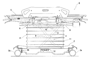
まず、車体フレーム2について説明する。図1,図2に示すように、この車体フレーム2は四隅にキャスター2a,2a,・・・を装着して前後左右に移動自在とし、該キャスター2a,2a,・・・を制動するためのブレーキ2bを備えて構成したものである。
そして、この車体フレーム2にX字状に構成したリンクフレーム8の一方を回動自在に支承するとともに、他方を該車体フレーム2に沿ってスライドまたは転動自在に構成して取り付けている。そして、このリンクフレーム8の上側の一方を図3に示す昇降フレーム9の軸受9a,9aに回動自在に取り付けるとともに、他方をレール部9b,9bに沿ってスライドまたは転動自在に構成して取り付けている。
なお、昇降機構3の駆動手段10は該昇降フレーム9に設けた取付ブラケット9cに一端部を軸止するとともに他端部を前記リンクフレーム8の一方に軸止している。
そして、前記車体フレーム2と昇降フレーム9間に前記昇降機構3を覆うジャバラ状のカバー部材11を止着して支柱4を構成している。なお、図においては駆動手段10としてアクチュエータを示しているが、本願発明において駆動手段や昇降機構を限定するものではなく、後述する載置台5を昇降可能に構成したものであれば良い。
First, the body frame 2 will be described. As shown in FIGS. 1 and 2, the vehicle body frame 2 is mounted with casters 2a, 2a,... At four corners so as to be movable back and forth and left and right, and brakes the casters 2a, 2a,. The brake 2b is provided.
Then, one of the X-shaped link frames 8 is rotatably supported on the vehicle body frame 2 and the other is configured to be slidable or rollable along the vehicle body frame 2. One of the upper side of the link frame 8 is rotatably attached to the bearings 9a and 9a of the elevating frame 9 shown in FIG. 3, and the other is configured to be slidable or rollable along the rail portions 9b and 9b. It is attached.
The driving means 10 of the elevating mechanism 3 has one end fixed to the mounting bracket 9 c provided on the elevating frame 9 and the other end fixed to one of the link frames 8.
A bellows-like cover member 11 that covers the lifting mechanism 3 is fixed between the body frame 2 and the lifting frame 9 to constitute the column 4. In the drawing, an actuator is shown as the driving means 10, but the driving means and the lifting mechanism are not limited in the present invention, and any mounting table 5 to be described later may be configured so as to be lifted and lowered.

前述のように構成した昇降機構3によれば、前記駆動手段10の伸縮により、前記リンクフレーム8が開閉し、昇降フレーム9が前記車体フレーム2に対して昇降する。
なお、前記駆動手段10の制御装置については図示していないが、図1に示すように車体フレーム2に上昇ペダル及び下降ペダルからなる昇降ペダル12を支柱4に対して対称となるように配置し、この昇降ペダル12を踏込むことによって上昇操作及び下降操作できるよう構成しておくと、両手で患者の安全確保を行いながら昇降操作することができ安全なものとすることができる。
According to the lifting mechanism 3 configured as described above, the link frame 8 is opened and closed and the lifting frame 9 is lifted and lowered with respect to the vehicle body frame 2 by the expansion and contraction of the driving means 10.
Although the control device for the driving means 10 is not shown in the figure, as shown in FIG. 1, as shown in FIG. 1, an elevating pedal 12 composed of an ascending pedal and a descending pedal is arranged symmetrically with respect to the column 4. If the lifting and lowering operations can be performed by depressing the lifting / lowering pedal 12, the lifting and lowering operation can be performed while ensuring the safety of the patient with both hands, which can be made safe.

続いて、スライド機構6について説明する。
このスライド機構6は、前記昇降フレーム9に止着するベースフレーム13と、スライドフレーム14及び、ボトムフレーム15とから主に構成し、前記スライドフレーム14には駆動手段16及び連動機構17を設けて前記ベースフレーム13に対して前記ボトムフレーム15が大きくベッドB側にはみ出すようにスライドするように構成したものである。
以下、各部の構成について説明する。
Next, the slide mechanism 6 will be described.
The slide mechanism 6 is mainly composed of a base frame 13 fixed to the elevating frame 9, a slide frame 14, and a bottom frame 15. The slide frame 14 is provided with a driving means 16 and an interlocking mechanism 17. The bottom frame 15 is configured to slide with respect to the base frame 13 so as to protrude toward the bed B side.
Hereinafter, the configuration of each unit will be described.

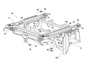
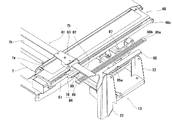
まず、図3に基づきベースフレーム13について説明する。
このベースフレーム13は、前記昇降フレーム9に固定するための取付プレート18,18を備えており、該取付プレート18にはスライドフレーム14を支持するための第一支持プレート19を立設状態で固着し、該第一支持プレート19,19を複数の連結パイプ20,20,20で繋いでいる。
前記支持プレート19には前上方に支軸19aを固着し、後上方にはブラケット部19bを設け、図4に示すように転動自在にローラー21を支承している。
一方、前記取付プレート18の前後には第二支持プレート22,22を固着している。該第二支持プレート22,22の上部には、互いに対向する空孔部22a,22aを設けるとともに、前方側の第二支持プレート22には上下方向のレール部22bを設けている。
このように構成したベースフレーム13は、上記昇降フレーム9に固着したナット部材9d,9d,・・・にそれぞれの取付プレート18,18に穿設した空孔部18a,18aを合わせ、螺子を螺着して固定する。
First, the base frame 13 will be described with reference to FIG.
The base frame 13 includes mounting plates 18 and 18 for fixing to the elevating frame 9, and a first support plate 19 for supporting the slide frame 14 is fixed to the mounting plate 18 in an upright state. The first support plates 19, 19 are connected by a plurality of connecting pipes 20, 20, 20.
A support shaft 19 is fixed to the support plate 19 on the front upper side, and a bracket part 19b is provided on the rear upper side, and a roller 21 is supported so as to roll freely as shown in FIG.
On the other hand, the second support plates 22 and 22 are fixed before and after the mounting plate 18. The upper portions of the second support plates 22 and 22 are provided with hole portions 22a and 22a that face each other, and the second support plate 22 on the front side is provided with a vertical rail portion 22b.
In the base frame 13 configured as described above, the holes 18a and 18a formed in the respective mounting plates 18 and 18 are aligned with the nut members 9d, 9d,. Wear and fix.

前記ベースフレーム13の両側部には、図4に示すようにボトム支持フレーム25,25を取り付けている。
このボトム支持フレーム25は、左右対称状に構成したものであるので、ここでは一方側の構成について説明する。
ボトム支持フレーム25は、パイプを曲折して平面視においてブーツ型の枠パイプ25aを形成し、内部の適所に補強パイプ25bを固着するとともに、外側寄りに後述するボトムフレーム15を支持するボトム支持プレート25cを固着し、該ボトム支持プレート25cの上面にライナー部材25dを止着して構成している。
As shown in FIG. 4, bottom support frames 25, 25 are attached to both sides of the base frame 13.
Since the bottom support frame 25 is configured symmetrically, the configuration on one side will be described here.
The bottom support frame 25 bends the pipe to form a boot-type frame pipe 25a in a plan view, and a reinforcing pipe 25b is fixed at an appropriate position inside, and a bottom support plate that supports a bottom frame 15 described later on the outer side. 25c is fixed, and a liner member 25d is fixed to the upper surface of the bottom support plate 25c.

上記構成によるボトム支持フレーム25は、前記ベースフレーム13に設けた空孔部22a,22aに回動自在に軸承している。
そして、前記ボトム支持フレーム25に固着しているブラケット25eと前記ベースフレーム13に固着している支点プレート18bに伸縮調節自在なガスシリンダー26を取り付けている。また、前記ブラケット25eには背上げレバー27を軸承して、該ガスシリンダー26の伸縮調節ができる構成としている。
このように構成した左右のボトム支持フレーム25は、それぞれ前記背上げレバー27を操作して、前記ガスシリンダー26を伸長あるいは縮退させることで、背上げしたり水平に戻したりできるよう構成している。
なお、本実施例ではこのように背上げできるように構成しているが、前記ベースフレーム13と一体となるよう固着して構成し、水平状態でのみ使用する形態であっても何ら問題はない。
The bottom support frame 25 having the above-described configuration is rotatably supported in the hole portions 22a and 22a provided in the base frame 13.
A gas cylinder 26 is attached to a bracket 25e fixed to the bottom support frame 25 and a fulcrum plate 18b fixed to the base frame 13 so as to be adjustable. Further, the bracket 25e is supported by a back raising lever 27 so that the expansion and contraction of the gas cylinder 26 can be adjusted.
The left and right bottom support frames 25 configured as described above are configured so that they can be raised or returned to the horizontal by operating the back raising lever 27 and extending or retracting the gas cylinder 26, respectively. .
In the present embodiment, it is configured so that it can be raised in this way, but there is no problem even if it is configured to be fixed so as to be integrated with the base frame 13 and used only in a horizontal state. .

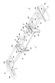
次にスライドフレーム14について説明する。
該スライドフレーム14は、平面視においてスライド方向側に開放したコ字状に構成している。詳述すると、図5に示すように、L字プレート28aの上面の中央部にパイプ28bを固着してガイド部材28を構成し、左右のガイド部材28,28の前端部にフレームパイプ29を固着して構成している。
そして、このスライドフレーム14には、上述したように駆動手段16と連動機構17が設けられている。
Next, the slide frame 14 will be described.
The slide frame 14 is formed in a U-shape that is open to the slide direction side in a plan view. More specifically, as shown in FIG. 5, a pipe 28b is fixed to the center of the upper surface of the L-shaped plate 28a to form a guide member 28, and a frame pipe 29 is fixed to the front ends of the left and right guide members 28, 28. Configured.
The slide frame 14 is provided with the driving means 16 and the interlocking mechanism 17 as described above.

まず、駆動手段16について説明する。前記フレームパイプ29の両側部近傍には、取付プレート30,31を止着し、一方の取付プレート30に動力源となるモーター32を固定している。
前記モーター32の出力軸には第一スプロケット33を止着している。また、左右の取付プレート30,31には、両端部にベベルギア34,34を止着してなる連動軸35を軸受けしている。なお、この連動軸35にはモーター32の出力軸側のベベルギア34に隣接する状態で第二スプロケット36を止着している。
そして、左右のベベルギア34,34にそれぞれ対応するベベルギア37と第三スプロケット38を駆動軸39に止着して、該ベベルギア37を前記ベベルギア34に噛合させるとともに、前記ガイド部材28の前方部に第三スプロケット38が位置するように配置している。
そして、第一スプロケット33と第二スプロケット36に駆動チェーン40を張設して駆動手段16を構成している。
なお、図面においては、駆動手段16の制御装置等を図示していないが、昇降フレーム9にバッテリーを配置し、このバッテリーからモーター32に電力を供給して、該モーター32の正逆回転を制御できるものとするように構成してもよい。そして、モーター32の正逆回転の操作を行うためのスイッチは、スライドフレーム14に具備した駆動手段16のカバー部材に設けておくと使い勝手がよいものとなる。
First, the driving means 16 will be described. In the vicinity of both sides of the frame pipe 29, mounting plates 30 and 31 are fixed, and a motor 32 serving as a power source is fixed to one mounting plate 30.
A first sprocket 33 is fixed to the output shaft of the motor 32. Further, the left and right mounting plates 30 and 31 are supported by an interlocking shaft 35 formed by fixing bevel gears 34 and 34 to both ends. A second sprocket 36 is fixed to the interlocking shaft 35 in a state adjacent to the bevel gear 34 on the output shaft side of the motor 32.
Then, the bevel gear 37 and the third sprocket 38 corresponding to the left and right bevel gears 34 and 34 are fixed to the drive shaft 39, respectively, and the bevel gear 37 is engaged with the bevel gear 34 and the front portion of the guide member 28 is The three sprockets 38 are arranged so as to be located.
A drive chain 40 is stretched between the first sprocket 33 and the second sprocket 36 to constitute the drive means 16.
In the drawing, the control device of the driving means 16 is not shown, but a battery is arranged on the lifting frame 9 and power is supplied from the battery to the motor 32 to control forward / reverse rotation of the motor 32. You may comprise so that it can do. If a switch for performing forward / reverse rotation operation of the motor 32 is provided on the cover member of the driving means 16 provided in the slide frame 14, it is easy to use.

次に、前記連動機構17について説明する。
前記ガイド部材28の後端部には従動ローラー41を軸承した調節部材42を螺着しており、該従動ローラー41と前記第三スプロケット38間に連結部材43とスライドフレーム支持プレート44を介在させて、作動チェーン45をループ状に張設している。詳述すると、第三スプロケット38を迂回する第一チェーン45aと前記従動ローラー41を迂回する第二チェーン45bの一端部を連結部材43に止着するとともに、他端部をスライドフレーム支持プレート44に止着している。なお、前記第一チェーン45aと第二チェーン45bは略等しい長さとし、前記スライドフレーム支持プレート44は上記ベースフレーム13に止着しており、クランク状に曲折して前記L字プレート28aを迂回する形状としている。また、連結部材43の他端側には空孔部43aを設け、該空孔部43aとボトムフレーム15を連結して、連動機構17を構成している。
なお、図5,6においては各チェーンの図示を省略している。
Next, the interlocking mechanism 17 will be described.
An adjusting member 42 bearing a driven roller 41 is screwed to the rear end of the guide member 28, and a connecting member 43 and a slide frame support plate 44 are interposed between the driven roller 41 and the third sprocket 38. Thus, the operating chain 45 is looped. More specifically, one end of the first chain 45a that bypasses the third sprocket 38 and the second chain 45b that bypasses the driven roller 41 are fixed to the connecting member 43, and the other end is connected to the slide frame support plate 44. It is fixed. The first chain 45a and the second chain 45b have substantially the same length, and the slide frame support plate 44 is fixed to the base frame 13 and bends in a crank shape to bypass the L-shaped plate 28a. It has a shape. In addition, a hole 43 a is provided on the other end side of the connecting member 43, and the interlocking mechanism 17 is configured by connecting the hole 43 a and the bottom frame 15.
5 and 6, illustration of each chain is omitted.

前述のようにベースフレーム13にスライドフレーム14を取り付けたとき、該スライドフレーム14の後部は、ベースフレーム13に支承したローラー21,21に支持された状態にある。一方、該スライドフレーム14の前方側は、スライドリンク46を介してベースフレーム13に支持されている。
このスライドリンク46は、前記フレームパイプ29の両端にそれぞれ固着したリンク取付プレート47に設けた空孔部47aに支承される第一リンク46aと、上記ベースフレーム13の支軸19aに支承される第二リンク46bとからなり、該第二リンク46bの他端部を前記第一リンク46aの中間部に軸承している。そして、第一リンク46aの他端部にはローラー46cを支承して、ベースフレーム13のレール部22b内に挿通してベースフレーム13に該スライドフレーム14を前後に移動自在となる状態で支持したものである。そして、左右の第一リンク46a,46aの間には補強部材46dを固着してスライドリンク46を構成している。
なお、このスライドフレーム14には、ギアやチェーン等が露出しないようにカバーが設けられるが図面においては省略している。
As described above, when the slide frame 14 is attached to the base frame 13, the rear portion of the slide frame 14 is supported by the rollers 21 and 21 supported on the base frame 13. On the other hand, the front side of the slide frame 14 is supported by the base frame 13 via a slide link 46.
The slide link 46 is supported by a first link 46 a supported by a hole 47 a provided in a link mounting plate 47 fixed to both ends of the frame pipe 29, and a first link 46 a supported by the support shaft 19 a of the base frame 13. It consists of two links 46b, and the other end of the second link 46b is supported by an intermediate portion of the first link 46a. A roller 46c is supported on the other end portion of the first link 46a and is inserted into the rail portion 22b of the base frame 13 so that the slide frame 14 is supported by the base frame 13 so as to be movable back and forth. Is. A reinforcing member 46d is fixed between the left and right first links 46a and 46a to constitute the slide link 46.
The slide frame 14 is provided with a cover so that gears, chains, etc. are not exposed, but are not shown in the drawing.

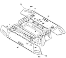
続いて、前記スライドフレーム14上に前記連結部材43,43を介して具備されるボトムフレーム15について説明する。
図7においては、中部ボトムフレーム48と、該中部ボトムフレーム48の両側にそれぞれ回動自在に取り付ける側部ボトムフレーム49,49とから構成してなるボトムフレーム14を図示している。
まず、中部ボトムフレーム48は、前記スライドフレーム14のガイド部材28,28を覆う下方開放の略コ字状のスライドプレート48a,48aを備えている。そして、このスライドプレート48a,48aの前後端面にはそれぞれブラケットプレート48b,48cを固着している。該ブラケットプレート48b,48cには中部ボトムフレーム48の左右方向で外側となる箇所に同一軸心で空孔部48dを穿設している。
そして、この両側に配置したスライドプレート48a,48a間にアンダーカバープレート48eを固着するとともに補強部材48f,48fを固着して構成している。なお、前記アンダーカバープレート48eには窓部48g,48gを設け、この窓部48g,48gに前記連結部材43,43を位置させ、前記スライドプレート48a,48aにそれぞれ固着したナット部材48h,48hに螺子止めして連動動作するよう構成している。
なお、この中部ボトムフレーム48の後部側には、ブラケット部48i,48iを設けて、上下に揺動自在となる揺動部材50を支承している。該揺動部材50の先端側には回転自在となるようにローラーパイプ50aを支承している。
Next, the bottom frame 15 provided on the slide frame 14 via the connecting members 43 and 43 will be described.
In FIG. 7, a bottom frame 14 configured by an intermediate bottom frame 48 and side bottom frames 49 and 49 that are rotatably attached to both sides of the intermediate bottom frame 48 is illustrated.
First, the middle bottom frame 48 is provided with substantially U-shaped slide plates 48 a and 48 a that are open downward and cover the guide members 28 and 28 of the slide frame 14. Bracket plates 48b and 48c are fixed to the front and rear end surfaces of the slide plates 48a and 48a, respectively. The bracket plates 48b and 48c are provided with holes 48d with the same axial center at locations on the outer side in the left-right direction of the middle bottom frame 48.
The under cover plate 48e is fixed between the slide plates 48a and 48a arranged on both sides, and the reinforcing members 48f and 48f are fixed. The under cover plate 48e is provided with windows 48g, 48g. The connecting members 43, 43 are positioned in the windows 48g, 48g, and nut members 48h, 48h fixed to the slide plates 48a, 48a, respectively. It is configured to be interlocked with screws.
Bracket portions 48i and 48i are provided on the rear side of the middle bottom frame 48, and a swing member 50 that can swing up and down is supported. A roller pipe 50a is supported on the tip side of the swing member 50 so as to be rotatable.

次に、前記側部ボトムフレーム49は、矩形状に構成したフレーム枠49aの中部ボトムフレーム側にブラケットプレート49b,49bを固着している。また、反対側にはカバー(図示省略)の取付部材49c,49cを固着している。この側部ボトムフレーム49の後部側には空孔部49d,49dを設けて、前記中部ボトムフレーム48と同様に、揺動部材50を支承している。
このように構成した側部ボトムフレーム49は前記中部ボトムフレーム48に連結軸51,51を挿通して回動自在に固定している。
Next, the side bottom frame 49 has bracket plates 49b and 49b fixed to the middle bottom frame side of a rectangular frame frame 49a. Further, attachment members 49c and 49c of a cover (not shown) are fixed to the opposite side. Holes 49d and 49d are provided on the rear side of the side bottom frame 49, and the swing member 50 is supported in the same manner as the middle bottom frame 48.
The side bottom frame 49 configured as described above is fixed to the middle bottom frame 48 through the connecting shafts 51 and 51 so as to be rotatable.

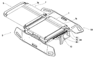
前述のように中部ボトムフレーム48と側部ボトムフレーム49,49とからなるボトムフレーム15は、図8に示すように上記スライドフレーム14に取り付ける。
詳述すると、スライドフレーム14のガイド部材28の上面にはそれぞれカバー部材もしくはライナー部材(図示省略)が止着されており、該カバー部材と中部ボトムフレーム48のスライドプレート48a,48aの内面が接当する状態となるように中部ボトムフレーム48を載置し、作動チェーン45に連結した連結部材43の空孔部43aを中部ボトムフレーム48のナット部材48hに合わせ、ボルト部材52を螺着して取り付けている。
このように構成したボトムフレーム15は、スライドフレーム14とボトム支持フレーム25,25のライナー部材25d,25dによって支持されており、ボトム支持フレーム25を上方回動することで、側部ボトムフレーム49も上方回動することができる構成となっている。
なお、上述したように、ベースフレーム13にボトム支持フレーム25を固着して構成した場合には、このボトムフレーム15も中部ボトムフレーム48と側部ボトムフレーム49,49を固着して一体的なものとしても良い。
また、これら中部ボトムフレーム48及び側部ボトムフレーム49には、それぞれクッション性のあるマットを取り付けるとともに、それぞれにカバーが止着されて載置台5を構成するが、図面においてはそれぞれの構成及び位置関係をより明確に示すために図示することを省略している。
As described above, the bottom frame 15 including the middle bottom frame 48 and the side bottom frames 49 and 49 is attached to the slide frame 14 as shown in FIG.
More specifically, a cover member or a liner member (not shown) is fixed to the upper surface of the guide member 28 of the slide frame 14, and the cover member and the inner surfaces of the slide plates 48a, 48a of the middle bottom frame 48 are in contact with each other. The middle bottom frame 48 is placed so as to be in contact, the hole 43a of the connecting member 43 connected to the operating chain 45 is aligned with the nut member 48h of the middle bottom frame 48, and the bolt member 52 is screwed. It is attached.
The bottom frame 15 configured as described above is supported by the slide frame 14 and the liner members 25d and 25d of the bottom support frames 25 and 25, and the side bottom frame 49 is also rotated by rotating the bottom support frame 25 upward. It is configured to be able to rotate upward.
As described above, when the bottom support frame 25 is fixed to the base frame 13, the bottom frame 15 is also integrally formed by fixing the middle bottom frame 48 and the side bottom frames 49, 49. It is also good.
In addition, a cushioning mat is attached to each of the middle bottom frame 48 and the side bottom frame 49 and a cover is secured to each of the middle bottom frame 48 and the side bottom frame 49 to form the mounting table 5. Illustration is omitted to show the relationship more clearly.

次に、載置台5の両側に具備されるサイドレール53,54について説明する。
まず、図2において、左側に具備する第一サイドレール53のロック機構55について説明する。
このロック機構55は、第一サイドレール53のサイドレールボード53aの内部に止着する支持部材56を備えている。この支持部材56は、左右の支持プレート56a,56aを連結パイプ56bで連結するとともに、上部には固定プレート56c,56cを固着して構成している。なお、支持プレート56aには、ガイド孔56dと取付孔56eを設けている。さらに、連結パイプ56bの中央部にはガイドピン56fを固着している。
また、ロック片57aを備えたロックプレート57を備えている。該ロック片57aは前記ガイド孔56dに挿通されており、該ロックプレート57の反対側には左右方向の規制孔57bと作動ピン57cを設けている。
また、前記サイドレールボード53aに設けたレバー操作孔53bにはレバー58を配し、該レバー58に掛止する連動プレート59を取り付けている。該連動プレート59の下部には上下方向の規制孔59aが穿設されるとともに斜め下方向きの作動孔59bを設けている。
そして、連動プレート59に設けた規制孔59aに支持部材56のガイドピン56fを挿通するとともに、左右のロックプレート57のそれぞれの規制孔57bも同様に挿通する。また、ロックプレート57の作動ピン57cを連動プレート59の作動孔59bに挿通するとともに、左右のロックプレート57,57が離間方向に付勢されるようにスプリング60を取り付けている。
このように構成したロック機構55は、カバープレート61をサイドレールボード53aに止着してカバーリングされている。
Next, the side rails 53 and 54 provided on both sides of the mounting table 5 will be described.
First, the lock mechanism 55 of the first side rail 53 provided on the left side in FIG. 2 will be described.
The lock mechanism 55 includes a support member 56 that is fixed inside the side rail board 53 a of the first side rail 53. The support member 56 is configured by connecting left and right support plates 56a and 56a with a connection pipe 56b, and fixing plates 56c and 56c to the upper part. The support plate 56a is provided with a guide hole 56d and an attachment hole 56e. Further, a guide pin 56f is fixed to the central portion of the connecting pipe 56b.
Moreover, the lock plate 57 provided with the lock piece 57a is provided. The lock piece 57a is inserted into the guide hole 56d, and a restricting hole 57b and a working pin 57c in the left-right direction are provided on the opposite side of the lock plate 57.
A lever 58 is disposed in the lever operation hole 53b provided in the side rail board 53a, and an interlocking plate 59 that is hooked on the lever 58 is attached. In the lower part of the interlocking plate 59, a vertical regulating hole 59a is formed and an obliquely downward working hole 59b is provided.
Then, the guide pins 56f of the support member 56 are inserted into the restriction holes 59a provided in the interlocking plate 59, and the restriction holes 57b of the left and right lock plates 57 are similarly inserted. Further, the operating pin 57c of the lock plate 57 is inserted into the operating hole 59b of the interlocking plate 59, and the spring 60 is attached so that the left and right lock plates 57, 57 are urged in the separating direction.
The lock mechanism 55 configured as described above is covered by fixing the cover plate 61 to the side rail board 53a.

このように構成した第一サイドレール53は、上記スライドフレーム14のリンク取付プレート47に穿設した取付孔47bと前記支持部材56aに設けた取付孔56eにボルト部材62を螺着して図11に示すように回動自在に取り付けている。
そして、図12に示すように第一サイドレール53が立設している状態では、図9の左側に示すようにスプリング60の付勢力で左右のロックプレート57,57が離間する方向に移動されるとともに、前記リンク取付プレート47,47に設けられたロック孔47c,47cにロック片57a,57aが挿通され、立設状態を保持している。
該第一サイドレール53を回動するには、図9の右側に示すようにレバー58を引き上げ、ガイドピン56fに沿って連動プレート59を引き上げる。すると、ロックプレート57,57が規制孔57bと作動ピン57cの作用により水平状態を維持しながら、スプリング60の付勢力に抗して接近する。これにより、ロック片57a,57aがリンク取付プレート47,47のロック孔47c,47cから抜け、回動自在な状態となり、図12の仮想線に示す下方回動した状態とすることができる。
The first side rail 53 thus configured has a bolt member 62 screwed into a mounting hole 47b formed in the link mounting plate 47 of the slide frame 14 and a mounting hole 56e provided in the support member 56a. As shown in FIG.
Then, when the first side rail 53 is erected as shown in FIG. 12, the left and right lock plates 57, 57 are moved away from each other by the urging force of the spring 60 as shown on the left side of FIG. At the same time, the lock pieces 57a and 57a are inserted into the lock holes 47c and 47c provided in the link mounting plates 47 and 47, and the upright state is maintained.
In order to rotate the first side rail 53, the lever 58 is pulled up as shown on the right side of FIG. 9, and the interlocking plate 59 is pulled up along the guide pin 56f. Then, the lock plates 57 and 57 approach against the urging force of the spring 60 while maintaining the horizontal state by the action of the restriction hole 57b and the operating pin 57c. As a result, the lock pieces 57a, 57a are removed from the lock holes 47c, 47c of the link mounting plates 47, 47 and can be rotated, and can be rotated downward as indicated by phantom lines in FIG.

次に第二サイドレール54のロック機構63について説明する。
このロック機構63も前述のロック機構55と同様にサイドレールボード54aの内部に設けている。さらに、このロック機構55もサイドレールボード54aに設けたレバー操作孔54bに位置させるレバー64と連動プレート65により作動するよう構成している。
まず、支持部材66は、支持プレート66a,66aの上端に連結パイプ66bを固着するとともに、上部に取付プレート66c,66cも固着されており、前記サイドレールボード54aに止着される。なお、前記支持プレート66aには、それぞれガイドピン66d及びガイドプレート66eが固着されており、これらに対応するガイド溝67aを設けるとともに下端部がロック片67bとなるロックプレート67を配している。
そして、前記連動プレート65に掛止した作動プレート68の両端部に設けた作動片68a,68aを前記ロックプレート67,67に設けた空孔部67c,67cに挿通するとともに、前記支持部材66と該作動プレート68との間にスプリング69,69を挿通している。
このように構成したロック機構63は、カバープレート61をサイドレールボード54aに止着してカバーリングされている。
Next, the lock mechanism 63 of the second side rail 54 will be described.
This locking mechanism 63 is also provided inside the side rail board 54a in the same manner as the locking mechanism 55 described above. Further, the lock mechanism 55 is also configured to be operated by a lever 64 and an interlocking plate 65 positioned in a lever operation hole 54b provided in the side rail board 54a.
First, the support member 66 has the connection pipe 66b fixed to the upper ends of the support plates 66a and 66a, and the attachment plates 66c and 66c are also fixed to the upper part, and is fixed to the side rail board 54a. A guide pin 66d and a guide plate 66e are fixed to the support plate 66a, respectively, and a guide groove 67a corresponding to these is provided, and a lock plate 67 having a lower end portion serving as a lock piece 67b is disposed.
Then, operating pieces 68a and 68a provided at both ends of the operating plate 68 hooked to the interlocking plate 65 are inserted into holes 67c and 67c provided in the lock plates 67 and 67, and the support member 66 and Springs 69 and 69 are inserted between the operating plate 68.
The lock mechanism 63 configured in this manner is covered by fixing the cover plate 61 to the side rail board 54a.

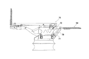
このように構成した第二サイドレール54は、図3及び図4に示すように、ベースフレーム13に固着している取付プレート23,23に取り付けている。まず、該取付プレート23には空孔部23aが設けられ、一方の取付プレート23には規制軸23bを固着している。
前記空孔部23a,23aには第一リンク70,70を支承するとともに、該第一リンク70,70の他端部に前記第二サイドレール54の支持プレート66a,66aに設けた空孔部66f,66fを支承している。また、一方の支持プレート66aに固着した軸部材66gと前記規制軸23bには第二リンク71を支承している。なお、第二リンク71の規制軸23b側には略へ字状のガイド溝71aを設けている。
As shown in FIGS. 3 and 4, the second side rail 54 configured in this manner is attached to the attachment plates 23 and 23 fixed to the base frame 13. First, the mounting plate 23 is provided with a hole portion 23a, and a regulating shaft 23b is fixed to one mounting plate 23.
The first links 70 and 70 are supported in the holes 23a and 23a, and the holes provided in the support plates 66a and 66a of the second side rail 54 at the other end of the first links 70 and 70. 66f and 66f are supported. A second link 71 is supported by the shaft member 66g fixed to one support plate 66a and the restriction shaft 23b. Note that a substantially groove-shaped guide groove 71 a is provided on the regulation shaft 23 b side of the second link 71.

このように取り付けた第二サイドレール54は、立設状態では、第一リンク70の下端部が昇降フレーム9あるいはベースフレーム13に接当して回動が拘束された状態とし、第一リンク70の上端部に設けたロック溝70aに上記ロック片67bが嵌り、回動不能な状態となる。
レバー64を引き上げると、左右のロックプレート67,67が引き上げられ、ロック片67b,67bがロック溝70a,70aから抜け、回動自在な状態となり、図12の仮想線に示す倒伏状態とすることができる。
In the standing state, the second side rail 54 attached in this manner is in a state in which the lower end portion of the first link 70 is in contact with the elevating frame 9 or the base frame 13 and the rotation is restrained. The lock piece 67b fits into the lock groove 70a provided at the upper end of the lens, so that it cannot rotate.
When the lever 64 is pulled up, the left and right lock plates 67 and 67 are pulled up, and the lock pieces 67b and 67b are pulled out of the lock grooves 70a and 70a, so that the levers can be freely rotated. Can do.

なお、本願発明のスライド機構6を作動させるときには、図13に示すように第二サイドレール54を略水平状に倒伏させて、ボトムフレーム15側に向けて押し込むように回動させる。すると、ガイドピン66dがベースフレーム13の取付部材24,24に取り付けたフック部材72に掛止され、水平状態を保持する構成となっている。
詳述すると、前記取付部材24,24にはそれぞれガイド溝24a,24aが設けられており、該取付部材24,24の間にフック部材72を取り付けている。
該フック部材72は、連動軸72aの両端にフックプレート72b,72bを固着するとともに、中央部に解除プレート72cを固着してなるものである。
そして、図12に示すように上方回動側に付勢するスプリング73を介在させている。
When operating the slide mechanism 6 of the present invention, as shown in FIG. 13, the second side rail 54 is laid down substantially horizontally and rotated so as to be pushed toward the bottom frame 15 side. Then, the guide pin 66d is hooked on the hook member 72 attached to the attachment members 24, 24 of the base frame 13, and the horizontal state is maintained.
More specifically, the mounting members 24 and 24 are provided with guide grooves 24 a and 24 a, respectively, and a hook member 72 is mounted between the mounting members 24 and 24.
The hook member 72 has hook plates 72b and 72b fixed to both ends of the interlocking shaft 72a, and a release plate 72c fixed to the center.
As shown in FIG. 12, a spring 73 that biases upward is interposed.

このように構成したフック部材72によれば、第二サイドレール54を押し込むと、フックプレート72b,72bに設けた案内面によりスプリング73の付勢力に抗して該フック部材72が下方回動され、第二サイドレール54のガイドピン66dが掛止され、当該第二サイドレール54が水平状態で保持される。このとき、解除プレート72cが作動プレート68に設けた空孔部68bに掛止されており、前記レバー64を引くと、該フック部材72が下方回動され、第二サイドレール54を引き出し、立設状態とすることができるよう構成したものである。   According to the hook member 72 configured in this manner, when the second side rail 54 is pushed in, the hook member 72 is rotated downward against the biasing force of the spring 73 by the guide surfaces provided on the hook plates 72b and 72b. The guide pins 66d of the second side rail 54 are hooked, and the second side rail 54 is held in a horizontal state. At this time, the release plate 72c is hooked in the hole 68b provided in the operation plate 68, and when the lever 64 is pulled, the hook member 72 is rotated downward, the second side rail 54 is pulled out, It is comprised so that it can be set as an installation state.

なお、左右のボトム支持プレート25,25の少なくとも一方が水平状態にないときには、ボトム支持フレーム25に固着したストッパープレート25fに第二サイドレール54が接触し、保持できる位置まで押し込むことができないように構成している。これは、第二サイドレール54を水平状態で保持した状態、すなわち、ボトムフレーム15が水平な状態でのみスライド機構6が作動するように構成するためのものであり、前記フック部材72の取付部に図示してはいないが検知手段を設けることで、誤作動することなく、安全にスライド機構6を使用できるものとすることができる。   When at least one of the left and right bottom support plates 25, 25 is not in a horizontal state, the second side rail 54 comes into contact with the stopper plate 25f fixed to the bottom support frame 25 so that it cannot be pushed to a position where it can be held. It is composed. This is for the structure in which the slide mechanism 6 operates only when the second side rail 54 is held in a horizontal state, that is, when the bottom frame 15 is horizontal, and the mounting portion of the hook member 72 Although not shown in the figure, by providing the detection means, the slide mechanism 6 can be used safely without malfunction.

次に、上述のように構成してなるストレッチャーSのスライド機構6の作用について説明する。なお、図14から図15において、(a)図はスライド機構の要部平面図、(b)図は要部側面図である。
図14は、図2に示したストレッチャーSの状態でのベースフレーム13とスライドフレーム14及びボトムフレーム15を移動させるための連結部材43を示している。
まず、この状態では、スライドリンク46が開いた状態でスライドフレーム14の前部を支持している。このとき、ベースフレーム13に止着しているスライドフレーム支持プレート44は、作動チェーン45の後端に位置し、逆に連結部材43は作動チェーン45の前端に位置している。
Next, the operation of the slide mechanism 6 of the stretcher S configured as described above will be described. 14 to 15, (a) is a plan view of the main part of the slide mechanism, and (b) is a side view of the main part.
FIG. 14 shows a connecting member 43 for moving the base frame 13, the slide frame 14, and the bottom frame 15 in the state of the stretcher S shown in FIG.
First, in this state, the front portion of the slide frame 14 is supported with the slide link 46 opened. At this time, the slide frame support plate 44 fixed to the base frame 13 is positioned at the rear end of the operating chain 45, and conversely, the connecting member 43 is positioned at the front end of the operating chain 45.

この状態から駆動手段16のモーター32を正回転させ、第三スプロケット38を図14(a)において時計周りの回転となるように作動させる。すると、作動チェーン45が回転され、図15に示すように、第三スプロケット38がスライドフレーム支持プレート44側に接近する。この接近した移動量の分だけ連結部材43は第三スプロケット38から離間する。この移動に伴ってスライドリンク46は先端のローラー46cがレール部22b内を転動しながら、閉じた状態となって前記スライドフレーム14を支持している。
さらに、モーター32を正回転させ、第三スプロケット38を時計回りに回転させると、図16に示すように、スライドフレーム支持プレート44は、作動チェーン45の前端に位置し、逆に連結部材43は作動チェーン45の後端に位置している。
From this state, the motor 32 of the drive means 16 is rotated forward, and the third sprocket 38 is operated to rotate clockwise in FIG. Then, the operation chain 45 is rotated, and the third sprocket 38 approaches the slide frame support plate 44 side as shown in FIG. The connecting member 43 is separated from the third sprocket 38 by the amount of the approaching movement. Along with this movement, the slide link 46 is in a closed state and supports the slide frame 14 while the roller 46c at the tip rolls in the rail portion 22b.
Further, when the motor 32 is rotated forward and the third sprocket 38 is rotated clockwise, the slide frame support plate 44 is positioned at the front end of the operating chain 45 as shown in FIG. It is located at the rear end of the operating chain 45.

このように、モーター32の正逆回転が第三スプロケット38の正逆回転となり、この第三スプロケット38の回転が作動チェーン45の正逆回転となるように構成している。さらに、スライドフレーム14を基準とすると、該作動チェーン45に止着する連結部材43とスライドフレーム支持プレート44は逆方向に移動するように配置している。
したがって、ベースフレーム13に対してスライドフレーム14が移動した分だけ、スライドフレーム14に対してボトムフレーム15が移動するので、ボトムフレーム15の移動量がスライドフレーム14のガイド部材28の長さの2倍近いものとなり、載置台5の幅を広く構成することなく、ボトムフレーム13の移動量が十分確保できるものとなっている。
In this way, the forward / reverse rotation of the motor 32 is the forward / reverse rotation of the third sprocket 38, and the rotation of the third sprocket 38 is the forward / reverse rotation of the working chain 45. Furthermore, when the slide frame 14 is used as a reference, the connecting member 43 and the slide frame support plate 44 fixed to the operating chain 45 are arranged so as to move in the opposite directions.
Therefore, since the bottom frame 15 moves relative to the slide frame 14 by the amount that the slide frame 14 moves relative to the base frame 13, the amount of movement of the bottom frame 15 is two times the length of the guide member 28 of the slide frame 14. The amount of movement of the bottom frame 13 can be sufficiently secured without making the mounting table 5 wide.

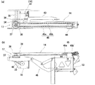
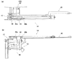
図17は、上記構成のスライド機構6を備えたストレッチャーSの作動状態を示している。
図(a)は、ベッドBにストレッチャーSを横付けして、スライド操作できる状態とした様子を示している。
図(b)は、スライド機構6を作動させて、載置台5(ボトムフレーム15)をベッドB側に移動させた状態を示している。
図示しているように、スライド機構6を備えたストレッチャーSによれば、ベッドBに横付けした状態から、スライド機構6を作動させて載置台5すなわち、ボトムフレーム15全体をベッドB上に位置させるまでスライドさせることができる。
したがって、ベッドBのフレームが低床下され、ストレッチャーSの車体フレーム2をベッドBのフレーム下に挿通できないような場合であっても、本願スライド機構6を備えたストレッチャーSであれば、ベッドBに接するように横付けして、スライド機構6を作動させると、ベッドBの略中間部まで載置台5をスライドさせることができる。
FIG. 17 shows an operating state of the stretcher S provided with the slide mechanism 6 having the above-described configuration.
The figure (a) has shown the mode that the stretcher S was put sideways on the bed B, and it was made the state which can be slid.
FIG. 2B shows a state where the slide mechanism 6 is operated and the mounting table 5 (bottom frame 15) is moved to the bed B side.
As shown in the drawing, according to the stretcher S provided with the slide mechanism 6, the slide mechanism 6 is operated from the state of being laid on the bed B to position the mounting table 5, that is, the entire bottom frame 15 on the bed B. Can be slid until
Therefore, even if the frame of the bed B is under the floor and the body frame 2 of the stretcher S cannot be inserted under the frame of the bed B, the stretcher S provided with the sliding mechanism 6 of the present invention If the slide mechanism 6 is operated so as to be in contact with B and the slide mechanism 6 is operated, the mounting table 5 can be slid to the substantially middle portion of the bed B.

次に、前記スライド機構6の作動によってベッドBとの間を往復移動する載置台5に設けた移載ベルト7による移載機構1について説明する。
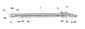
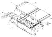
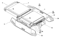
まず、前記移載ベルト7は中部ボトムフレーム48及び側部ボトムフレーム49,49に略同様の構成で取り付ける。ここでは、図18に基づいて中部ボトムフレーム48に取り付ける移載ベルト7について説明する。
まず、中部ボトムフレーム48は上述した構成であり、この中部ボトムフレーム48の下面側に固着している補強部材48f及びアンダープレートカバー48eから上方に離間して前記中部ボトムフレーム48にマットフレーム74を止着している。なお、該マットフレーム74にはクッション部材74aが止着されるとともに布あるいはレザー等でできたカバー(図示省略)を縫着している。
一方、前記移載ベルト7は、前後両端部にそれぞれ線ファスナー7aを縫い付けるとともに、該線ファスナー7aの後部には後述する作動具75を挿通するための筒部7bを設けている。
このように構成した移載ベルト7は、前記アンダープレートカバー48e等とマットフレーム74との間を通し、前記中部ボトムフレーム48の前後に回転自在に支承しているローラーパイプ50a,50bを迂回して前記マットフレーム74の上面で前記線ファスナー7aを閉め、無端状の移載ベルト7となるよう構成している。
なお、このように構成することで、線ファスナー7aを外して一方側を引き抜くと移載ベルト7を外すことができ、また前述のように容易に取り付けることもできるので、該移載ベルト7が汚れたとき等に交換し易いものとなっている。
Next, the transfer mechanism 1 using the transfer belt 7 provided on the mounting table 5 that reciprocates between the bed B by the operation of the slide mechanism 6 will be described.
First, the transfer belt 7 is attached to the middle bottom frame 48 and the side bottom frames 49, 49 with substantially the same configuration. Here, the transfer belt 7 attached to the middle bottom frame 48 will be described with reference to FIG.
First, the middle bottom frame 48 has the above-described configuration, and the mat frame 74 is attached to the middle bottom frame 48 while being spaced upward from the reinforcing member 48f and the under plate cover 48e fixed to the lower surface side of the middle bottom frame 48. It is fixed. A cushion member 74a is fixed to the mat frame 74 and a cover (not shown) made of cloth or leather is sewn.
On the other hand, the transfer belt 7 has sewn wire fasteners 7a at both front and rear ends, and a cylindrical portion 7b for inserting an operating tool 75 described later at the rear of the wire fastener 7a.
The transfer belt 7 configured as described above passes between the under plate cover 48e and the like and the mat frame 74 and bypasses the roller pipes 50a and 50b rotatably supported on the front and rear of the middle bottom frame 48. Thus, the linear fastener 7 a is closed on the upper surface of the mat frame 74 to form an endless transfer belt 7.
With this configuration, the transfer belt 7 can be removed when the wire fastener 7a is removed and one side is pulled out, and the transfer belt 7 can be easily attached as described above. It is easy to replace when dirty.

なお、上記側部ボトムフレーム49については図示していないが、側部ボトムフレーム49のフレーム枠49aの下面にアンダープレートカバーを止着する一方、中部ボトムフレーム48と同様にマットフレームを該アンダープレートカバーから上方に離間させて止着し、前述と同様に構成した移載ベルト7を取り付けるものとする。   Although the side bottom frame 49 is not shown, the under plate cover is fixed to the lower surface of the frame frame 49a of the side bottom frame 49, while the mat frame is attached to the under plate in the same manner as the middle bottom frame 48. It is assumed that the transfer belt 7 having the same structure as described above is attached by being spaced apart from the cover and fixed.

次に、前記移載ベルト7に設けた筒部7bに挿通する作動具75について説明する。
該作動具75は、上記中部ボトムフレーム48と側部ボトムフレーム49,49を回動自在に連結している連結軸51,51にそれぞれ挿通するスライド規制具76,76を備えている。
該スライド規制具76には、図20に示すように前記連結軸51に挿通するための空孔部76aと、水平方向のスライド溝76bと、縦方向のガイド溝76cを設けるとともに、前方下部に切欠き状の掛止部76dを設けている。そして、前記ガイド溝76cには前方下面に傾斜部77aを備えるとともに、長孔状の取付孔77bとスプリング取付部77cを設けてなる解除プレート77を後方に付勢するスプリング78を挿通した状態でピン79により止着している。このように構成したスライド規制具76では、解除プレート77がスプリング78の付勢力によって後方位置にあるときには前記掛止部76dに掛止可能であり、前記スプリング78に抗して解除プレート77が前方に押し出されると前記傾斜部77aによって掛止状態が解除されるように作用するものである。
Next, the operation tool 75 inserted through the cylindrical portion 7b provided on the transfer belt 7 will be described.
The actuating tool 75 includes slide restricting tools 76 and 76 that are respectively inserted into connecting shafts 51 and 51 that rotatably connect the middle bottom frame 48 and the side bottom frames 49 and 49.
As shown in FIG. 20, the slide restricting device 76 is provided with a hole 76a for passing through the connecting shaft 51, a horizontal slide groove 76b, and a vertical guide groove 76c, and at the front lower portion. A notch-shaped latching portion 76d is provided. The guide groove 76c has an inclined portion 77a on the front lower surface, and a spring 78 that urges the release plate 77 provided with a long attachment hole 77b and a spring attachment portion 77c to the rear. It is fixed by a pin 79. In the slide restricting device 76 configured as described above, when the release plate 77 is in the rear position by the biasing force of the spring 78, the release plate 77 can be hooked on the hook portion 76d, and the release plate 77 is moved forward against the spring 78. When it is pushed out, it acts so that the latching state is released by the inclined portion 77a.

前述のスライド規制具76には、固定部材80が固着される。該固定部材80には空孔部80a及び雌ねじ部80bを設けている。
そして、中部ボトムフレーム48の両側部に取り付けたスライド規制具76には中部ボトムフレーム48に装着した移載ベルト7の筒部7bに挿通するスライドプレート81と、側部ボトムフレーム49に装着した移載ベルト7の筒部7bに挿通するスライドプレート82を止着する。
なお、スライドプレート81には両端部に空孔部81aを穿設しており、スライドプレート82には一端部に回動筒82aを固着するとともに固定ブラケット83に回動自在に軸着している。該固定ブラケット83には空孔部83aと下方に突出する状態で固定ピン83b,83bが固着してあり、該固定ピン83b,83bを前記スライドプレート81の空孔部81a,81a及び固定部材80の空孔部80aに挿通して前記雌ねじ部80bに合わせてねじ止めして固定している。
A fixing member 80 is fixed to the slide restricting device 76 described above. The fixing member 80 is provided with a hole portion 80a and a female screw portion 80b.
The slide restrictor 76 attached to both sides of the middle bottom frame 48 includes a slide plate 81 inserted into the cylindrical portion 7b of the transfer belt 7 attached to the middle bottom frame 48 and a transfer plate attached to the side bottom frame 49. The slide plate 82 inserted through the cylindrical portion 7b of the loading belt 7 is fixed.
The slide plate 81 has holes 81a at both ends. The slide plate 82 has a rotating cylinder 82a fixed to one end and is pivotally attached to the fixed bracket 83. . Fixing pins 83b and 83b are fixed to the fixing bracket 83 so as to protrude downward from the air holes 83a. The fixing pins 83b and 83b are fixed to the air holes 81a and 81a and the fixing member 80 of the slide plate 81, respectively. The hole 80a is inserted into the female screw portion 80b and fixed to the female screw portion 80b.

このように構成した作動具75は、ねじを緩めることで簡単に移載ベルト7から取り外すことができる。そのため、前述したように移載ベルト7の交換が簡単にできる構成となっている。
また、この作動具は、固定ブラケット83が回動自在な構成となっているので、上記ボトム支持フレーム25に設けた背上げレバー27の操作によって背上げした際にも側部ボトムフレーム49の動きに追従して回動され、移動時等には背上げして楽な姿勢をとることもできるように構成したものとなっている。
The operating tool 75 configured as described above can be easily detached from the transfer belt 7 by loosening a screw. Therefore, as described above, the transfer belt 7 can be easily replaced.
Further, since the fixing bracket 83 is rotatable in this operating tool, the movement of the side bottom frame 49 also occurs when the back is raised by operating the back raising lever 27 provided on the bottom support frame 25. It is configured such that it can be rotated following the movement and can be lifted up to take an easy posture when moving.

次に、上記スライド機構6を作動して上記載置台5をベッドB側へ移動する際に前記スライド規制具76の移動を保持する第一保持機構84について説明する。
該第一保持機構84は、上記ベースフレーム13の前後の第二支持プレート22,22の上面に固着したガイドプレート85に前後に摺動自在に取り付けたスライド規制部材86を備えている。
詳述すると、前記ガイドプレート85はクランク状に曲折されたプレートであり、中央部には空孔部85aを穿設している。また、前記スライド規制部材86は左右に二連の平行なスライド孔86a,86bを設けたプレートであり、外側のスライド孔86aに固定軸87を挿通して前記ガイドプレート85の空孔部85aに固定している。
また、前記スライド規制具76に設けたスライド溝76bには前記スライド規制部材86の内側を挿通し、スライド規制具76に軸止する規制ピン88が前記スライド孔86bを通る状態で取り付けて構成している。
なお、これらスライド規制具76及びスライド規制部材86の後端部は前記中部ボトムフレーム48のブラケットプレート48cに接触する位置に設けている。また、図21においては、一方の第一保持機構84を示しているが、他方の連結軸51側にも対称状に第一保持機構84を設けている。
これらの作用については後述する。
Next, the first holding mechanism 84 that holds the movement of the slide restricting tool 76 when the slide mechanism 6 is operated to move the table 5 to the bed B side will be described.
The first holding mechanism 84 includes a slide regulating member 86 slidably attached to the guide plate 85 fixed to the upper surfaces of the second support plates 22 and 22 on the front and rear sides of the base frame 13.
More specifically, the guide plate 85 is a plate bent in a crank shape, and has a hole 85a at the center. The slide restricting member 86 is a plate provided with two parallel slide holes 86a and 86b on the left and right sides, and a fixed shaft 87 is inserted into the outer slide hole 86a to enter the hole 85a of the guide plate 85. It is fixed.
Further, a slide groove 76b provided in the slide restricting tool 76 is inserted into the inside of the slide restricting member 86, and a restricting pin 88 which is fixed to the slide restricting tool 76 is attached in a state passing through the slide hole 86b. ing.
The rear end portions of the slide restricting tool 76 and the slide restricting member 86 are provided at positions where they contact the bracket plate 48c of the middle bottom frame 48. In FIG. 21, one first holding mechanism 84 is shown, but the first holding mechanism 84 is also provided symmetrically on the other connecting shaft 51 side.
These actions will be described later.

続いて、上記スライド機構6を作動して上記載置台5を反ベッドB側へ移動する際に前記スライド規制具76の移動を保持する第二保持機構89について説明する。
該第二保持機構89は、主要な構成部を第二サイドレール54に設けている。
まず、前記ロック機構63の支持部材66には作動ワイヤー90のアウター90aを固定するための固定プレート66hを固着するとともに、左右に回動軸66i,66iを固着している。
該回動軸66i,66iにはストッパー部材91,91を支承している。なお、該ストッパー部材91の一端側にはスプリング92を配して、通常ストッパー部材91がカバープレート61内に収まる方向に回動するように付勢している。
該ストッパー部材91,91は、一対の作動プレート93,93の先端に止着した凹凸状となるよう曲折してなる押上カム94,94によって作動する。
なお、前記作動プレート93,93は反転カム95によって連結されており、一方の作動プレート93に固着した固定プレート93aに前記作動ワイヤー90のインナー90bを止着している。なお、前記作動プレート93,93間にはスプリング96を張設して、互いの作動プレート93,93を接近する方向に付勢している。この状態では、押上カム94の谷部がストッパー部材91に接しており、前記スプリング96に抗して作動ワイヤー90のインナー90bを引くと、互いの作動プレート93,93が離間して押上カム94の山部にストッパー部材91が接して押し上げられる。このストッパー部材91が押し上げられた状態を図23に示している。
なお、前記作動ワイヤー90の他端部は、図26に示すようにボトム支持フレーム25に設けた取付ブラケット25gに上下回動自在に軸承したレバー部材97に取り付けており、該レバー部材97の上下回動操作により、前記ストッパー部材91,91を作動できる構成としている。
Next, the second holding mechanism 89 that holds the movement of the slide restricting tool 76 when the slide mechanism 6 is operated to move the mounting table 5 to the side opposite to the bed B will be described.
The second holding mechanism 89 is provided with main components on the second side rail 54.
First, a fixing plate 66h for fixing the outer 90a of the operating wire 90 is fixed to the support member 66 of the lock mechanism 63, and rotating shafts 66i and 66i are fixed to the left and right.
Stopper members 91 and 91 are supported on the rotary shafts 66i and 66i. Note that a spring 92 is disposed on one end side of the stopper member 91 and normally biased so as to rotate in a direction in which the stopper member 91 is accommodated in the cover plate 61.
The stopper members 91, 91 are operated by push-up cams 94, 94 that are bent so as to have a concavo-convex shape fixed to the tips of the pair of operation plates 93, 93.
The operating plates 93 and 93 are connected by a reversing cam 95, and an inner 90b of the operating wire 90 is fixed to a fixed plate 93a fixed to one operating plate 93. A spring 96 is stretched between the operating plates 93 and 93 to bias the operating plates 93 and 93 toward each other. In this state, the valley portion of the push-up cam 94 is in contact with the stopper member 91, and when the inner wire 90 b of the operation wire 90 is pulled against the spring 96, the operation plates 93 and 93 are separated from each other and the push-up cam 94 is separated. The stopper member 91 comes into contact with the peak portion and is pushed up. FIG. 23 shows a state where the stopper member 91 is pushed up.
As shown in FIG. 26, the other end of the operating wire 90 is attached to a lever member 97 that is supported by a mounting bracket 25g provided on the bottom support frame 25 so as to be rotatable up and down. The stopper members 91 and 91 can be operated by a turning operation.

本実施例における移載機構1は、前述のように支柱4の上部に取り付けたベースフレーム13と、該ベースフレーム13にスライド機構6を介して取り付けたボトムフレーム15からなる載置台5の間に構成したもので、この載置台5のベッドB等との間での往復移動に連動して作用するように構成したものである。
詳述すると、前記載置台5の幅方向に巻回した無端状の移載ベルト7の上面に位置する筒部7bに作動具75のスライドプレート81,82を挿通するとともに、前記載置台5がベッドB側に移動する際に前記作動具75のスライド規制具76を前記ベースフレーム13から一定間隔で保持する第一保持機構84と、前記載置台5がベッドB側から戻る際に前記作動具75のスライド規制具76を前記ベースフレーム13から一定間隔で保持する第二保持機構89とからなるものとしている。
このように、載置台5の往復移動によって作用する移載機構1を設けているので、個別に駆動力を必要とすることなく、簡単なものとすることができた。
As described above, the transfer mechanism 1 according to the present embodiment is provided between the mounting frame 5 including the base frame 13 attached to the upper portion of the column 4 and the bottom frame 15 attached to the base frame 13 via the slide mechanism 6. It is configured so as to operate in conjunction with reciprocal movement between the mounting table 5 and the bed B or the like.
More specifically, the slide plate 81, 82 of the operating tool 75 is inserted into the cylindrical portion 7b positioned on the upper surface of the endless transfer belt 7 wound in the width direction of the table 5, and the table 5 A first holding mechanism 84 that holds the slide restricting tool 76 of the operating tool 75 at a predetermined interval from the base frame 13 when moving to the bed B side, and the operating tool when the mounting table 5 returns from the bed B side. The second holding mechanism 89 holds 75 slide restricting tools 76 from the base frame 13 at regular intervals.
Thus, since the transfer mechanism 1 which acts by the reciprocating movement of the mounting table 5 is provided, it can be simplified without requiring a separate driving force.

次に、上記構成の移載機構1の作用について説明する。なお、図24から図29においては、一方の側部ボトムフレーム49とボトム支持フレーム25を図示せず、第一保持機構84及び第二保持機構89の作用状態を示している。
まず、移載を行う前に図17(a)に示すようにベッドBに横付けして、載置台5を水平状態とするとともに第二サイドレール54を水平保持して、ベッドBとの高さを合わせる。なお、このとき移載ベルト7に設けた筒部7bは図24に示すように載置台5のベッドB側に位置している。
この状態からスライド機構6を作動させて、載置台5をベッドB側に移動する。このとき、スライド規制具76の規制ピン88がスライド規制部材86を引っ張り、図25に示すように固定軸87がスライド孔86aの端部に位置する状態まで前記移載ベルト7は載置台5に対する相対的な位置を変えない。
Next, the operation of the transfer mechanism 1 having the above configuration will be described. 24 to 29, one side bottom frame 49 and the bottom support frame 25 are not shown, and the operating states of the first holding mechanism 84 and the second holding mechanism 89 are shown.
First, before transfer, it is laid on the bed B as shown in FIG. 17 (a) so that the mounting table 5 is in a horizontal state and the second side rail 54 is held horizontally, and the height with the bed B is set. Adjust. At this time, the cylindrical portion 7b provided on the transfer belt 7 is positioned on the bed B side of the mounting table 5 as shown in FIG.
From this state, the slide mechanism 6 is operated to move the mounting table 5 to the bed B side. At this time, the restricting pin 88 of the slide restricting tool 76 pulls the slide restricting member 86, and the transfer belt 7 moves relative to the placing table 5 until the fixed shaft 87 is located at the end of the slide hole 86 a as shown in FIG. 25. Do not change the relative position.

さらに、スライド機構6を作動すると、固定軸87によってスライド規制部材86が摺動できない状態となっているため、作動具75も移動しない状態にある。そのため、載置台5がベッドB側に移動するのに対して移載ベルト7の筒部7bはベースフレーム13に対して一定の位置を保持する。したがって、載置台5上に位置する移載ベルト7の上面はその位置が保持され、載置台5が患者とベッドBの間に入り込む際に、患者とこの移載ベルト7との間ではずれが生じないものとなっている。なお、このとき移載ベルト7の下面側は載置台5の後部を迂回して上面側に送り出されているが、ボトムフレーム15に止着しているアンダープレートカバー48eがベッドB等との接触面となるので過剰な摩擦が加わることはないものとなっている。
そして、図26に示すように作動具75が載置台5の前方部に位置すると患者が載置台5上に移載できた状態となっている。
このように、ベッドBの上面と移載ベルト7の上面とは相対的な移動がない状態であるので、載置台5が患者とベッドBとの間に容易に滑り込み、載置台5の上に違和感や不快感を与えることなく、患者の移載が行われる。
Further, when the slide mechanism 6 is operated, the slide restricting member 86 cannot be slid by the fixed shaft 87, so that the operating tool 75 is not moved. Therefore, while the mounting table 5 moves to the bed B side, the cylindrical portion 7 b of the transfer belt 7 holds a fixed position with respect to the base frame 13. Therefore, the position of the upper surface of the transfer belt 7 positioned on the mounting table 5 is maintained, and when the mounting table 5 enters between the patient and the bed B, there is a deviation between the patient and the transfer belt 7. It does not occur. At this time, the lower surface side of the transfer belt 7 bypasses the rear portion of the mounting table 5 and is sent to the upper surface side. However, the underplate cover 48e fixed to the bottom frame 15 is in contact with the bed B or the like. Since it becomes a surface, excessive friction is not added.
Then, as shown in FIG. 26, when the operating tool 75 is positioned in the front part of the mounting table 5, the patient can be transferred onto the mounting table 5.
As described above, since the upper surface of the bed B and the upper surface of the transfer belt 7 are not relatively moved, the mounting table 5 easily slides between the patient and the bed B and is placed on the mounting table 5. The patient is transferred without feeling uncomfortable or uncomfortable.

なお、この移載機構1では、前記第一保持機構84のスライド規制具76がスライド規制部材86によって保持される位置を水平保持している第二サイドレール54のベッドB側端部と載置台5の後部が略一致する位置としているので、ベッドB上の患者の傍にこの第二サイドレール54の端部を合わせることで、ベッドBに対するストレッチャーSの位置合わせを簡単なものとしている。   In the transfer mechanism 1, the bed B side end of the second side rail 54 and the mounting table that horizontally hold the position where the slide restricting tool 76 of the first holding mechanism 84 is held by the slide restricting member 86. Since the rear part 5 is in a substantially coincident position, the alignment of the stretcher S with respect to the bed B is simplified by aligning the end of the second side rail 54 with the patient on the bed B.

また、上述したように該第一保持機構84は、載置台5がベッドB側に移動する際に、ベースフレーム13から作動具75を一定間隔で保持できるように構成したものであればよく、本実施例ではスライド規制部材86をプレートで構成したものを図示している。
しかし、ベースフレーム13とスライド規制具76間にワイヤーを張設することによって、第一保持機構84を構成したものであっても、ワイヤーが伸長した状態で前記スライド規制具76を一定間隔に保持できるものとなり、このようにワイヤーを用いた構成としても何ら問題はない。なお、ワイヤーを用いた場合には、ベースフレーム13側にワイヤーの弛みをなくすための巻取手段等を設けておくことが好ましい。
Further, as described above, the first holding mechanism 84 only needs to be configured to hold the operating tool 75 from the base frame 13 at regular intervals when the mounting table 5 moves to the bed B side. In this embodiment, the slide restricting member 86 is constituted by a plate.
However, even if the first holding mechanism 84 is configured by stretching a wire between the base frame 13 and the slide restricting device 76, the slide restricting device 76 is held at a constant interval while the wire is extended. There is no problem even if the wire is used in this way. In addition, when using a wire, it is preferable to provide the winding means etc. for eliminating the slack of a wire in the base frame 13 side.

前述の状態からスライド機構6を反ベッドB側に作動すると、載置台5上に患者を載せた状態で図27に示すようにベースフレーム13上に載置台5が戻り、第一,第二サイドレール53,54を立設すると、移動可能な状態となる。
なお、このときにスライド規制部材86はスライド規制具76の規制ピン88によって引き戻されている。
When the slide mechanism 6 is operated to the side opposite to the bed B from the above-described state, the mounting table 5 returns to the base frame 13 with the patient placed on the mounting table 5, as shown in FIG. When the rails 53 and 54 are erected, they are movable.
At this time, the slide restricting member 86 is pulled back by the restricting pin 88 of the slide restricting tool 76.

次に、ストレッチャーS側からベッドBに患者を戻す際の作用について説明する。
図27に示す状態からスライド機構6を作動させてベッドB上に載置台5を移動する。このとき、作動具75及び筒部7bは載置台5の前方に位置した状態にあるので、上記第一保持機構84が作用することはない。
然る後、図28に示すようにボトム支持フレーム25に設けたレバー部材97を跳ね上げる。このレバー部材97を跳ね上げると、図23に示すように第二サイドレール54のカバープレート61からストッパー部材91,91が上方回動し、前記スライド規制具76に設けた掛止部76dにそれぞれ掛止する状態となる。
そして、スライド機構6を作動させて載置台5を反ベッドB側に移動すると、作動具75はその位置が保持された状態にあるので、患者とベッドBとの間から載置台5が抜き取られるように動作する。このときにも、上述と同様に患者と移載ベルト7との間にずれが生じないので、患者は違和感や不快感を感じることなく、ベッドBに戻ることができる。
Next, an operation when the patient is returned from the stretcher S side to the bed B will be described.
The slide mechanism 6 is operated from the state shown in FIG. 27 to move the mounting table 5 onto the bed B. At this time, since the operating tool 75 and the cylindrical portion 7b are located in front of the mounting table 5, the first holding mechanism 84 does not act.
Thereafter, the lever member 97 provided on the bottom support frame 25 is flipped up as shown in FIG. When the lever member 97 is flipped up, as shown in FIG. 23, the stopper members 91 and 91 are pivoted upward from the cover plate 61 of the second side rail 54, and are respectively attached to the latching portions 76 d provided on the slide restricting device 76. It becomes a state to hang.
When the slide mechanism 6 is operated to move the mounting table 5 to the side opposite to the bed B, the position of the operating tool 75 is maintained, so that the mounting table 5 is extracted from between the patient and the bed B. To work. Also at this time, since there is no deviation between the patient and the transfer belt 7 as described above, the patient can return to the bed B without feeling uncomfortable or uncomfortable.

前記保持具75が載置台5の後部に位置する状態となると、患者はベッドB上に移載できており、さらにスライド機構6を作動させると、図29に示すように第二保持機構89を作動するためのレバー部材96に載置台5の前部が接当し、レバー部材96を下方回動して第二保持機構89を解除する。このとき、図23に示すスライド規制具76の掛止部76dとストッパー部材91の掛止状態は解除される。なお、本実施例においては中部ボトムフレーム48の後部側のブラケットプレート48cがスプリング78に抗して解除プレート77を押し出すことで、解除プレート77に設けた傾斜部77aが強制的にストッパー部材91との掛止状態を解除できるようにも構成している。
この状態からさらにスライド機構6を作動すると、前記ブラケットプレート48cがスライド規制部材86を押しながら、図24に示す元の位置まで移動する。
When the holder 75 is positioned at the rear part of the mounting table 5, the patient has been transferred onto the bed B. When the slide mechanism 6 is further operated, the second holding mechanism 89 is moved as shown in FIG. The front portion of the mounting table 5 contacts the lever member 96 for operation, and the lever member 96 is rotated downward to release the second holding mechanism 89. At this time, the latching state of the latching portion 76d of the slide restricting tool 76 and the stopper member 91 shown in FIG. 23 is released. In the present embodiment, the bracket plate 48c on the rear side of the middle bottom frame 48 pushes the release plate 77 against the spring 78, so that the inclined portion 77a provided on the release plate 77 is forcibly connected to the stopper member 91. It is comprised so that the latching state of can be cancelled | released.
When the slide mechanism 6 is further operated from this state, the bracket plate 48c moves to the original position shown in FIG.

このように、本実施例における移載機構1は、載置台5に巻回した無端状の移載ベルト7を載置台5に対して作動させるもので、この移載ベルト7の上面に設けた筒部7bに挿通する作動具75を、スライド機構6によってベッドBとの間で往復移動するように構成した載置台5の移動方向と載置台5の位置に応じて適宜作用するよう構成した第一保持機構84及び第二保持機構89によってベースフレーム13から所定の位置で保持することにより、載置台5に対して相対的に移載ベルト7を回転させるよう構成したものである。
したがって、スライド機構6の駆動力のみで移載ベルト7を作動させることができるものとなっており、単一のモーターを制御するだけでよいので複雑なものとならず、結果として故障し難く、安価なものを提供できるという効果がある。
As described above, the transfer mechanism 1 in this embodiment operates the endless transfer belt 7 wound around the mounting table 5 with respect to the mounting table 5, and is provided on the upper surface of the transfer belt 7. The actuating tool 75 inserted through the cylindrical portion 7b is configured to act appropriately depending on the moving direction of the mounting table 5 configured to reciprocate between the bed B by the slide mechanism 6 and the position of the mounting table 5. The transfer belt 7 is configured to rotate relative to the mounting table 5 by being held at a predetermined position from the base frame 13 by the one holding mechanism 84 and the second holding mechanism 89.
Therefore, the transfer belt 7 can be operated only by the driving force of the slide mechanism 6, and since it is only necessary to control a single motor, it is not complicated, and as a result, it is difficult to break down. There is an effect that an inexpensive one can be provided.

また、この移載機構1にあっては、載置台5に患者を載せるときに、載置台5に対して移載ベルト7が作動し始める位置、すなわち第一保持機構84が作動して作動具75がベースフレーム13に対して一定の間隔で保持された状態となる位置(図25参照)をベッドB上に倒伏している第二サイドレール54の端部に載置台5の後端部が位置する状態としている。したがって、患者を移載する際には、この第二サイドレール54の端部を患者の傍に位置させることで適切な位置合わせができるという効果もある。
同様に、患者をベッドB側に移動させ終わる位置も第二サイドレール54の端部に載置台5の端部が位置する状態(図29参照)としているので、患者を降ろしたい位置に前記第二サイドレール54の端部を合わせておくことで、容易に所望の位置に患者を移載することができるという効果もある。
In the transfer mechanism 1, when the patient is placed on the mounting table 5, the position at which the transfer belt 7 starts to operate with respect to the mounting table 5, that is, the first holding mechanism 84 operates to actuate the tool. The rear end of the mounting table 5 is positioned at the end of the second side rail 54 that is lying on the bed B at a position (see FIG. 25) where 75 is held at a fixed interval with respect to the base frame 13. It is in a position. Therefore, when the patient is transferred, there is also an effect that proper alignment can be performed by positioning the end of the second side rail 54 near the patient.
Similarly, the position at which the patient is moved to the bed B side is also in a state where the end of the mounting table 5 is positioned at the end of the second side rail 54 (see FIG. 29). By matching the end portions of the two side rails 54, there is an effect that the patient can be easily transferred to a desired position.

また、移載ベルト7の上面に設けた筒部7bにスライドプレート81,82を挿通することで、該移載ベルト7を作動させるよう構成しているので、該スライドプレート81,82を筒部7bから抜き取り、線ファスナー7aを外し、移載ベルト7を一方側に抜き取ることで移載ベルト7を簡単に取り外すことができる。同様にアンダープレートカバー48eとマットフレーム74間に移載ベルト7を通して、前後のローラーパイプ50a,50bを迂回させ載置台5の上面で線ファスナー7aを閉じ、筒部7bにスライドプレート81,82を挿通すれば移載ベルト7を取り付けることができる。このように、簡単に移載ベルト7の交換ができるので、衛生的に使用できるものとなっている。   Further, since the transfer belt 7 is operated by inserting the slide plates 81 and 82 through the cylindrical portion 7b provided on the upper surface of the transfer belt 7, the slide plates 81 and 82 are connected to the cylindrical portion. The transfer belt 7 can be easily removed by removing it from 7b, removing the wire fastener 7a, and extracting the transfer belt 7 to one side. Similarly, the transfer belt 7 is passed between the under plate cover 48e and the mat frame 74, the front and rear roller pipes 50a and 50b are bypassed, the line fastener 7a is closed on the upper surface of the mounting table 5, and the slide plates 81 and 82 are attached to the cylindrical portion 7b. If it is inserted, the transfer belt 7 can be attached. Thus, since the transfer belt 7 can be easily replaced, it can be used in a sanitary manner.

さらに、前記作動具75は、固定ブラケット83でそれぞれのスライドプレート81,82を回動自在に固定しているので、載置台5を背上げした状態とすることもでき、搬送中には楽な姿勢で移動することができるものとなっている。
このように、この移載機構1を設けてなるストレッチャーSは、ベッドB等との間での往復移動量を大きくとることができるスライド機構6によって載置台5を取り回しのよいコンパクトな大きさとすることができるとともに、上述したように使い勝手のよいものとなっている。
Furthermore, since the operating tool 75 has the slide plates 81 and 82 rotatably fixed by the fixing bracket 83, the mounting table 5 can be in a state where the back is lifted up. It can be moved in a posture.
Thus, the stretcher S provided with the transfer mechanism 1 has a compact size that allows the mounting table 5 to be handled by the slide mechanism 6 that can take a large amount of reciprocation between the bed B and the like. As described above, it is easy to use.

1 移載機構
2 車体フレーム
3 昇降機構
4 支柱
5 載置台
6 スライド機構
7 移載ベルト
7a 線ファスナー
7b 筒部
13 ベースフレーム
15 ボトムフレーム
25 ボトム支持フレーム
48 中部ボトムフレーム
49 側部ボトムフレーム
51 連結軸
63 第二サイドレール
75 作動具
76 スライド規制具
81 スライドプレート
82 スライドプレート
84 第一保持機構
86 スライド規制部材
89 第二保持機構
91 ストッパー部材
S ストレッチャー
B ベッド
DESCRIPTION OF SYMBOLS 1 Transfer mechanism 2 Body frame 3 Elevating mechanism 4 Support column 5 Mounting base 6 Slide mechanism 7 Transfer belt 7a Wire fastener 7b Tube part 13 Base frame 15 Bottom frame 25 Bottom support frame 48 Middle bottom frame 49 Side bottom frame 51 Connecting shaft 63 Second Side Rail 75 Actuator 76 Slide Restrictor 81 Slide Plate 82 Slide Plate 84 First Holding Mechanism 86 Slide Restricting Member 89 Second Holding Mechanism 91 Stopper Member S Stretcher B Bed

Claims (4)

車体フレームに昇降機構を具備してなる支柱を立設し、該支柱上部にベースフレームを止着し、該ベースフレームにスライド機構を介して載置台を設けるとともに、前記載置台の移動側には少なくとも立設状態と水平状態で保持可能にサイドレールを具備してなるストレッチャーにおいて、両端に線ファスナーを縫着してなる移載ベルトを前記載置台の幅方向に巻回して無端状とし、該移載ベルトの上面に設けた筒部にはスライド規制具を備えた作動具に止着するスライドプレートを挿通するとともに、該スライド規制具を載置台の幅方向に止着した連結軸に挿通する一方、前記ベースフレームにはスライド規制部材を取り付け、前記載置台をベッド側に移動させる際、前記スライド規制具に止着する規制ピンが該スライド規制部材を引っ張り、該スライド規制部材のスライド孔に挿通する固定軸が該スライド孔の端部に位置する状態までは前記移載ベルトを前記載置台に対して相対的に位置を変えないようにし、さらに、前記スライド機構を作動させると、前記スライド規制部材により前記スライド規制具のベッド側への移動を保持するよう構成してなる第一保持機構と、前記載置台をストレッチャー側に移動させる際、前記スライド規制具の掛止部に前記サイドレールから出没操作自在に設けたストッパー部材を掛止することで、前記移載ベルトが前記載置台に対して相対的に位置を変えるよう前記スライド規制具のベッド側からの移動を保持するよう構成してなる第二保持機構とからなる移載機構を設けたことを特徴とするストレッチャー。 A support column comprising an elevating mechanism is erected on the body frame, a base frame is fixed to the upper part of the support column, a mounting table is provided on the base frame via a slide mechanism, and on the moving side of the mounting table, In a stretcher comprising side rails that can be held in at least a standing state and a horizontal state, a transfer belt formed by sewing line fasteners at both ends is wound in the width direction of the mounting table to make it endless. A cylindrical plate provided on the upper surface of the transfer belt is inserted with a slide plate that is fixed to an actuator provided with a slide restricting tool, and is inserted into a connecting shaft that is fixed in the width direction of the mounting table. to one, the mounting of the slide regulating member on the base frame, when moving the mounting table on the bed side, regulating pin fastened to the slide restriction device is pulling the slide regulating member The transfer belt is not changed in position relative to the mounting table until the fixed shaft inserted into the slide hole of the slide restricting member is located at the end of the slide hole. When the slide mechanism is operated, the first holding mechanism configured to hold the movement of the slide restricting tool toward the bed by the slide restricting member , and the slide when moving the mounting table to the stretcher side A bed of the slide restricting tool is arranged so that the transfer belt changes its position relative to the mounting table by hooking a stopper member provided so as to be able to protrude and retract from the side rail to the latching portion of the restricting tool. A stretcher provided with a transfer mechanism comprising a second holding mechanism configured to hold movement from the side. 上記第一保持機構により上記スライド規制具を保持する位置と、上記第二保持機構による前記スライド規制具の保持状態を解除する位置を上記サイドレールをベッド側に倒伏した状態でベッド側となる端部と上記載置台の後端が略一致する位置とした移載機構となるよう構成したことを特徴とする請求項1に記載のストレッチャー。     The position that holds the slide restricting tool by the first holding mechanism and the position that releases the holding state of the slide restricting tool by the second holding mechanism are the ends that become the bed side with the side rails lying down to the bed side. The stretcher according to claim 1, wherein the stretcher is configured to be a transfer mechanism in which the rear end of the mounting table and the rear end of the mounting table are substantially coincident with each other. 上記第二保持機構を、上記ベースフレームまたはボトム支持フレームに上下回動自在に設けたレバー部材の上方回動により上記ストッパー部材を上記サイドレールから突出するよう構成するとともに、載置台がストレッチャー側に戻る際に該レバー部材を倒伏して前記ストッパー部材の突出状態を解除する一方、前記スライド規制具にスライド自在に支承した解除プレートに前記載置台後部が接触することで該解除プレートに設けた傾斜部が前記スライド規制具とストッパー部材との係合状態を強制的に解除するよう構成してなる移載機構としたことを特徴とする請求項1あるいは請求項に記載のストレッチャー。 The second holding mechanism is configured such that the stopper member protrudes from the side rail by the upward rotation of a lever member provided on the base frame or the bottom support frame so as to be vertically rotatable, and the mounting table is on the stretcher side. The lever member is laid down when returning to the release state, and the protruding state of the stopper member is released, while the rear portion of the mounting table is in contact with the release plate that is slidably supported by the slide restricting tool. The stretcher according to claim 1 or 2 , wherein an inclined portion is a transfer mechanism configured to forcibly release the engagement state between the slide restricting tool and the stopper member. 上記ベースフレームの両側部に隣接するようにボトム支持フレームを上下回動操作自在に取り付けるとともに、前記載置台を中部ボトムフレームの両側部に上下回動自在となるよう側部ボトムフレームを取り付けて前記ベースフレーム及びボトム支持フレームで支持する構成とするとともに、それぞれに巻回した移載ベルトの筒部に挿通する作動具のスライドプレートを載置台の上下回動に応じて屈曲するようにそれぞれを回動自在に連設してなる作動具を備えた移載機構としたことを特徴とする請求項1あるいは請求項3に記載のストレッチャー。     The bottom support frame is attached so as to be vertically rotatable so as to be adjacent to both sides of the base frame, and the side bottom frame is attached to the both sides of the middle bottom frame so that the mounting table can be vertically rotated. The support frame is supported by the base frame and the bottom support frame, and the slide plate of the operating tool inserted through the cylindrical portion of the transfer belt wound around each is rotated so that the slide plate is bent according to the vertical rotation of the mounting table. The stretcher according to claim 1 or 3, wherein the transfer mechanism includes an actuating tool that is movably connected.
JP2010255457A 2010-11-16 2010-11-16 Stretcher with transfer mechanism Active JP5779764B2 (en)

Priority Applications (1)

Application Number Priority Date Filing Date Title
JP2010255457A JP5779764B2 (en) 2010-11-16 2010-11-16 Stretcher with transfer mechanism

Applications Claiming Priority (1)

Application Number Priority Date Filing Date Title
JP2010255457A JP5779764B2 (en) 2010-11-16 2010-11-16 Stretcher with transfer mechanism

Publications (2)

Publication Number Publication Date
JP2012105747A JP2012105747A (en) 2012-06-07
JP5779764B2 true JP5779764B2 (en) 2015-09-16

Family

ID=46492078

Family Applications (1)

Application Number Title Priority Date Filing Date
JP2010255457A Active JP5779764B2 (en) 2010-11-16 2010-11-16 Stretcher with transfer mechanism

Country Status (1)

Country Link
JP (1) JP5779764B2 (en)

Families Citing this family (7)

* Cited by examiner, † Cited by third party
Publication number Priority date Publication date Assignee Title
CN104207897B (en) * 2014-08-11 2016-06-01 孙艳艳 There is the operation transfer bed of air bag pushing structure
CN108578077A (en) * 2018-03-22 2018-09-28 河南科技大学第附属医院(河南省显微外科研究所) A kind of stretcher facilitating transfer patient
CN108403305A (en) * 2018-03-22 2018-08-17 河南科技大学第附属医院(河南省显微外科研究所) The special adjustable stretcher of emergency department
CN108578078A (en) * 2018-03-22 2018-09-28 河南科技大学第附属医院(河南省显微外科研究所) A kind of stretcher that bed board can slide laterally
CN109793614B (en) * 2019-03-27 2020-04-24 王海军 Safe carrying sickbed for fracture patients
CN111329666A (en) * 2020-03-05 2020-06-26 青岛大学附属医院 Rescue conveying device for cardiology department
CN113842285B (en) * 2021-10-15 2023-05-12 宁波职业技术学院 Manual patient transfer trolley and patient transfer method

Family Cites Families (6)

* Cited by examiner, † Cited by third party
Publication number Priority date Publication date Assignee Title
US3967328A (en) * 1974-09-06 1976-07-06 Cox Ellis V Load lifting and transferring device with multiple powered belts
JP3369038B2 (en) * 1996-01-12 2003-01-20 三洋電機株式会社 Control mechanism of transfer assistance device
JP2000225147A (en) * 1999-02-04 2000-08-15 Time:Kk Human body transfer unit apparatus
JP4644859B2 (en) * 2000-07-06 2011-03-09 株式会社いうら Side rail standing holding mechanism in stretcher
JP2004105352A (en) * 2002-09-17 2004-04-08 Toshimaro Nakatani Device for moving patient between adjacent beds
JP2010213963A (en) * 2009-03-18 2010-09-30 Panasonic Corp Transfer device

Also Published As

Publication number Publication date
JP2012105747A (en) 2012-06-07

Similar Documents

Publication Publication Date Title
JP5779764B2 (en) Stretcher with transfer mechanism
KR101406496B1 (en) Wheelchair with brake
US3414324A (en) Adjustable chair
US7712168B2 (en) Articulating bed and method of using the same
JP6412913B2 (en) Method for supporting transfer of care recipient using wheelchair, wheelchair, and transfer device
CN101001596A (en) Medical bed with an exercising means
JP5779763B2 (en) Slide mechanism of mounting table for stretcher etc.
JP6722668B2 (en) Assistance robot
JP5240695B2 (en) bed
KR101295603B1 (en) Pressing apparatus of sewing machine
JP2009106692A (en) Chair for nursing care
JP4255183B2 (en) child seat
JPS6345891B2 (en)
JP2008104813A5 (en)
JP4415967B2 (en) Chair type massage machine
TW200701913A (en) Childcare apparatus
CN102727241B (en) Mobile patient table
CN109044176B (en) Automatic defecation assisting paper pad mechanism for automatic clamping and dropping toilet door of toilet for toilet
JP2006187657A5 (en)
TWI664091B (en) Cold pressure-sensitive sticker transfer device
CN201020209Y (en) Foot fastener structure for handstand machine
JP2003079678A (en) Transfer caring support machine
JP5688652B2 (en) Body frame brake mechanism for stretchers, etc.
CN108760270B (en) Gas spring tensile test device
FI86595B (en) Movable arrangement for lifting, turning and/or moving a patient or a deceased person

Legal Events

Date Code Title Description
A621 Written request for application examination

Free format text: JAPANESE INTERMEDIATE CODE: A621

Effective date: 20131115

A977 Report on retrieval

Free format text: JAPANESE INTERMEDIATE CODE: A971007

Effective date: 20140818

A131 Notification of reasons for refusal

Free format text: JAPANESE INTERMEDIATE CODE: A131

Effective date: 20141001

A521 Request for written amendment filed

Free format text: JAPANESE INTERMEDIATE CODE: A523

Effective date: 20141129

TRDD Decision of grant or rejection written
A01 Written decision to grant a patent or to grant a registration (utility model)

Free format text: JAPANESE INTERMEDIATE CODE: A01

Effective date: 20150515

A61 First payment of annual fees (during grant procedure)

Free format text: JAPANESE INTERMEDIATE CODE: A61

Effective date: 20150610

R150 Certificate of patent or registration of utility model

Ref document number: 5779764

Country of ref document: JP

Free format text: JAPANESE INTERMEDIATE CODE: R150

R250 Receipt of annual fees

Free format text: JAPANESE INTERMEDIATE CODE: R250

R250 Receipt of annual fees

Free format text: JAPANESE INTERMEDIATE CODE: R250

R250 Receipt of annual fees

Free format text: JAPANESE INTERMEDIATE CODE: R250

R250 Receipt of annual fees

Free format text: JAPANESE INTERMEDIATE CODE: R250

R250 Receipt of annual fees

Free format text: JAPANESE INTERMEDIATE CODE: R250

R250 Receipt of annual fees

Free format text: JAPANESE INTERMEDIATE CODE: R250