JP5778980B2 - Evaluation of misalignment between tread transfer and shaping former using tread transfer - Google Patents
Evaluation of misalignment between tread transfer and shaping former using tread transfer Download PDFInfo
- Publication number
- JP5778980B2 JP5778980B2 JP2011108560A JP2011108560A JP5778980B2 JP 5778980 B2 JP5778980 B2 JP 5778980B2 JP 2011108560 A JP2011108560 A JP 2011108560A JP 2011108560 A JP2011108560 A JP 2011108560A JP 5778980 B2 JP5778980 B2 JP 5778980B2
- Authority
- JP
- Japan
- Prior art keywords
- tread
- axis
- ring
- laser distance
- shaping former
- Prior art date
- Legal status (The legal status is an assumption and is not a legal conclusion. Google has not performed a legal analysis and makes no representation as to the accuracy of the status listed.)
- Expired - Fee Related
Links
Images


Description
本発明は、トレッドトランスファーとシェーピングフォーマとの芯ズレを、迅速にかつ低コストで評価しうるトレッドトランスファー、及びそれを用いたトレッドトランスファーとシェーピングフォーマとの芯ズレ評価方法に関する。 The present invention relates to a tread transfer capable of evaluating core misalignment between a tread transfer and a shaping former quickly and at low cost, and a core misalignment evaluation method between the tread transfer and the shaping former using the tread transfer.
ラジアルタイヤにおける生タイヤ(加硫前のタイヤ)の製造工程では、予め形成した円筒状のトレッドリングに、トロイド状に膨張させた生タイヤ基体を押付けて一体に貼り付けすることが必要である。 In a manufacturing process of a raw tire (a tire before vulcanization) in a radial tire, it is necessary to press the raw tire base expanded in a toroidal shape onto a cylindrical tread ring formed in advance and attach it integrally.
この貼付方法としては、従来、図8(A)に示すように、トレッドトランスファーcを用い、トレッドリングAを、シェーピングフォーマdに保持された円筒状の生タイヤ基体Bの半径方向外側のトレッド貼付位置Qまで搬送して待機させる。その後、内圧充填により前記生タイヤ基体Bを円筒状からトロイド状に膨張させ、その膨張部分BaをトレッドリングAの半径方向内周面に押し付けて貼り付けることにより、前記生タイヤ基体BとトレッドリングAとが接合した生タイヤを形成している(例えば特許文献1、2参照。)。
Conventionally, as shown in FIG. 8A, this tapping method uses a tread transfer c, and the tread ring A is tread pasted on the outer side in the radial direction of the cylindrical green tire base B held by the shaping former d. Transport to position Q and wait. Thereafter, the raw tire base B and the tread ring are formed by inflating the raw tire base B from a cylindrical shape to a toroidal shape by internal pressure filling and pressing the inflated portion Ba against the inner circumferential surface of the tread ring A in the radial direction. A green tire joined with A is formed (see, for example,
このとき、トレッドトランスファーcの軸心と、シェーピングフォーマdの軸心とが位置ズレしたり、又軸心同士が傾いたりした場合には、タイヤのユニフォミティーの低下を招き、高品質のタイヤを形成することができなくなる。なお本明細書では、前記軸心同士の位置ズレ及び傾きを総称して芯ズレと呼んでいる。 At this time, if the axial center of the tread transfer c and the axial center of the shaping former d are misaligned, or if the axial centers are tilted, the uniformity of the tire is reduced, and a high-quality tire is produced. It cannot be formed. In the present specification, the positional deviation and inclination between the shaft centers are collectively referred to as a core deviation.
そこで従来においては、図8(B)に示すように、シェーピングフォーマdの支持軸d1上にダイヤルゲージなどの測定器eを固定し、トレッドトランスファーcにおけるトレッド保持リングc1の内周面までの半径方向距離kr、及びトレッド保持リングc1の側面までの距離kjを、前記支持軸d1を手動で廻しながら測定している。そして前記支持軸d1を一周させたときの前記距離krのバラツキにより同芯度を評価するとともに、前記距離kjのバラツキにより軸心の傾きを評価している。 Therefore, conventionally, as shown in FIG. 8B, a measuring instrument e such as a dial gauge is fixed on the support shaft d1 of the shaping former d, and the radius to the inner peripheral surface of the tread holding ring c1 in the tread transfer c. The directional distance kr and the distance kj to the side surface of the tread holding ring c1 are measured while manually rotating the support shaft d1. Then, the concentricity is evaluated by the variation of the distance kr when the support shaft d1 is rotated around, and the inclination of the shaft center is evaluated by the variation of the distance kj.
しかしこのような、評価方法では、測定に時間(例えば1〜2時間)がかかるため、生産性の観点から頻繁に行うことができないなど、生産ラインの精度低下を早期にフィードバックすることが難しい。 However, in such an evaluation method, since it takes time (for example, 1 to 2 hours) for measurement, it is difficult to feed back a decrease in the accuracy of the production line at an early stage, for example, from the viewpoint of productivity.
そこで本発明は、トレッドトランスファーのリング状移動台に、トレッド保持リングの軸心とは直角な基準面上においてシェーピングフォーマの支持軸までの距離を測定する第1、第2のレーザ距離センサを、各レーザ光が直交する向きで取り付けることを基本として、トレッドトランスファーとシェーピングフォーマとの芯ズレを、迅速に評価でき、生産ラインの精度低下を早期にフィードバックしうるとともに、装置コストの上昇を最小限に抑えうるトレッドトランスファー、及びそれを用いたトレッドトランスファーとシェーピングフォーマとの芯ズレ評価方法を提供することを目的としている。 Therefore, the present invention provides the first and second laser distance sensors for measuring the distance to the support shaft of the shaping former on a reference plane perpendicular to the axis of the tread holding ring on the ring-shaped moving table of the tread transfer. Based on the fact that each laser beam is mounted in an orthogonal direction, the misalignment between the tread transfer and the shaping former can be evaluated quickly, and a decrease in accuracy of the production line can be fed back at an early stage, and the increase in equipment cost is minimized. It is an object of the present invention to provide a tread transfer that can be suppressed to a low level, and a method for evaluating misalignment between a tread transfer and a shaping former using the tread transfer.
上記課題を解決するために、本願請求項1の発明は、トレッド成形ドラムとシェーピングフォーマとの間を軸心方向に往復移動しうるリング状移動台と、このリング状移動台に取り付きかつ内周面が縮径することにより前記トレッドリングの外周面に当接して該トレッドリングを同心に保持しうるトレッド保持リングとを具えるとともに、
前記リング状移動台に、
前記トレッド保持リングの軸心とは直角な基準面上にて前記軸心を通るX軸上に配されるとともに、前記シェーピングフォーマの支持軸までのX軸上の距離LXを測定する第1のレーザ距離センサと、
前記基準面上にて前記軸心を通りかつ前記X軸とは直交する向きのY軸上に配されるとともに、前記シェーピングフォーマの支持軸までのY軸上の距離LYを測定する第2のレーザ距離センサとを有し、
前記トレッド成形ドラムから受け取った前記トレッドリングを、前記シェーピングフォーマに保持された円筒状の生タイヤ基体の半径方向外側のトレッド貼付位置まで搬送しかつこのトレッド貼付位置で前記トレッドリングを保持するトレッドトランスファーを用いて、トレッドトランスファーとシェーピングフォーマとの芯ズレを評価する評価方法である。
In order to solve the above problems, the invention of
In the ring-shaped moving table,
A first L is disposed on the X axis passing through the axis on a reference plane perpendicular to the axis of the tread retaining ring and measures a distance LX on the X axis to the support axis of the shaping former. A laser distance sensor;
A second distance on the reference plane that passes through the axis and is perpendicular to the X axis and that measures a distance LY on the Y axis to the support axis of the shaping former; A laser distance sensor ,
A tread transfer that transports the tread ring received from the tread molding drum to a tread application position radially outward of a cylindrical green tire base held by the shaping former and holds the tread ring at the tread application position. This is an evaluation method for evaluating the misalignment between the tread transfer and the shaping former .
又本願請求項1の発明は、実測により、前記X軸がトレッド保持リングの内周面と交わる2つの交点Px1、Px2のうちの前記第1のレーザ距離センサが配される側の交点Px1から前記支持軸までのX軸上での距離Lx1の実測値Dx1、及び、他方の側の交点Px2から前記支持軸までのX軸上での距離Lx2の実測値Dx2、並びに前記Y軸がトレッド保持リングの内周面と交わる2つの交点Py1、Py2のうちの前記第2のレーザ距離センサが配される側の交点Py1から前記支持軸までのY軸上での距離Ly1の実測値Dy1、及び他方の交点Py2から前記支持軸までのY軸上での距離Ly2の実測値Dy2を、事前に求める第1の事前ステップと、
その時の前記第1、2のレーザ距離センサから前記支持軸までの距離LX、LYを、前記第1、2のレーザ距離センサを用いて測定してセンサ測定値Tx0、Ty0をうる第2の事前ステップとにより、
下記式(1)で示す第1のレーザ距離センサの補正値Exと、下記式(2)で示す第2のレーザ距離センサの補正値Eyとを予め求めることを特徴としている。
Ex=Tx0+(Dx2−Dx1)/2 −−−(1)
Ey=Ty0+(Dy2−Dy1)/2 −−−(2)
Further, the invention of
At this time, the distances LX and LY from the first and second laser distance sensors to the support shaft are measured using the first and second laser distance sensors to obtain sensor measurement values Tx0 and Ty0. Step by step
A correction value Ex of the first laser distance sensor expressed by the following formula (1) and a correction value Ey of the second laser distance sensor expressed by the following formula (2) are obtained in advance.
Ex = Tx0 + (Dx2-Dx1) / 2 ---- (1)
Ey = Ty0 + (Dy2−Dy1) / 2 −−− (2)
又本願請求項1の発明では、前記第1、2のレーザ距離センサにより、この第1、2のレーザ距離センサから前記支持軸までの距離LX、LYを測定してセンサ測定値Tx、Tyを求める測定ステップ、及び、
前記測定ステップで得たセンサ測定値Tx、Tyを、前記補正値Ex、補正値Eyにて補正した補正データKx(=Ex−Tx)、補正データKy(=Ey−Ty)に基づいて、同芯度を評価する同芯度評価ステップを有することを特徴としている。
In the first aspect of the present invention, the distances LX and LY from the first and second laser distance sensors to the support shaft are measured by the first and second laser distance sensors, and the sensor measurement values Tx and Ty are obtained. The desired measurement steps, and
Based on the correction data Kx (= Ex−Tx) and the correction data Ky (= Ey−Ty) obtained by correcting the sensor measurement values Tx and Ty obtained in the measurement step with the correction value Ex and the correction value Ey. It is characterized by having a concentricity evaluation step for evaluating the centrality.
又請求項2の発明では、前記トレッドトランスファーをシェーピングフォーマに対して軸心方向に所定距離LZを移動させ、その時の前記第1、2のレーザ距離センサから前記支持軸までのセンサ測定値Txの変化量ΔTx、及びセンサ測定値Tyの変化量ΔTyを測定して求める測定ステップと、
この変化量ΔTx、ΔTyに基づき、前記トレッド保持リングとシェーピングフォーマとの軸心の傾きを評価する傾き評価ステップとを含むことを特徴としている。
According to a second aspect of the present invention, the tread transfer is moved a predetermined distance LZ in the axial direction relative to the shaping former, and the sensor measurement value Tx from the first and second laser distance sensors to the support shaft at that time is measured. A measurement step for measuring and obtaining the change amount ΔTx and the change amount ΔTy of the sensor measurement value Ty;
The amount of change Delta] Tx, based on .DELTA.Ty, and inclination evaluation step of evaluating the inclination of the axis of the tread retaining ring and the shaping former is characterized in containing Mukoto.
本発明は叙上の如く、トレッドトランスファーのリング状移動台に、第1、第2の2つのレーザ距離センサを取り付けている。第1のレーザ距離センサは、トレッド保持リングの軸心とは直角な基準面上にて前記軸心を通るX軸上に配される。又第2のレーザ距離センサは、前記基準面上にて前記軸心を通りかつ前記X軸とは直交する向きのY軸上に配される。そして、前記第1、2のレーザ距離センサを用いて、それぞれシェーピングフォーマの支持軸までの距離を測定することで、後述する「発明を実施するための形態」で記載するように、トレッド保持リングの軸心とシェーピングフォーマの軸心との位置ズレ、及び傾きを評価することができる。 In the present invention, as described above, the first and second laser distance sensors are attached to the ring-shaped moving table of the tread transfer. The first laser distance sensor is disposed on the X axis passing through the axis on a reference plane perpendicular to the axis of the tread retaining ring. The second laser distance sensor is disposed on the Y axis passing through the axis on the reference plane and orthogonal to the X axis. Then, by measuring the distances to the support shafts of the shaping former using the first and second laser distance sensors, respectively, as described in “Mode for carrying out the invention” described later, a tread holding ring It is possible to evaluate the positional deviation and inclination between the axis of the shaft and the axis of the shaping former.
このレーザ距離センサによる距離の測定は、手間や労力を要することなく自動でかつ迅速に行いうるため、例えば生産ラインの稼働開始毎など頻繁に芯ズレのチェックを行うことができ、生産ラインの精度低下を早期にフィードバックさせることが可能となる。又2つのレーザ距離センサのみで行いうるため、装置コストの上昇を最小限に抑えることができる。 The distance measurement by this laser distance sensor can be performed automatically and quickly without requiring labor and labor, so it is possible to check for misalignment frequently, for example, every time the production line starts operation, and the accuracy of the production line It is possible to feed back the decrease early. In addition, since only two laser distance sensors can be used, an increase in apparatus cost can be minimized.
以下、本発明の実施の形態について、詳細に説明する。
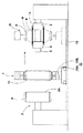
図1は、生タイヤ生産ラインの一部を示し、この生タイヤ形成ラインは、トレッドリングAを形成するトレッド成形ドラム2、生タイヤ基体Bを円筒状からトロイド状に膨張させるシェーピングフォーマ3、及びこのトレッド成形ドラム2とシェーピングフォーマ3との間を往復移動しうる前記トレッドトランスファー1を具える。
Hereinafter, embodiments of the present invention will be described in detail.
FIG. 1 shows a part of a raw tire production line, which includes a
そして、生タイヤ生産ラインでは、前記トレッドトランスファー1を用い、前記トレッド成形ドラム2から受け取ったトレッドリングAを、前記シェーピングフォーマ3に保持された円筒状の生タイヤ基体Bの半径方向外側のトレッド貼付位置Qまで搬送するとともに、このトレッド貼付位置QにてトレッドリングAを保持して待機する。しかる後、シェーピングフォーマ3によって前記生タイヤ基体Bをトロイド状に膨張させ、その膨張部分を前記トレッドリングAの内周面に押し付けて貼り付ける。これにより、前記生タイヤ基体BとトレッドリングAとが一体に接合された生タイヤが形成される。
In the raw tire production line, the
ここで、前記トレッド成形ドラム2は、拡縮径可能かつ回転自在な円筒状のドラム2Aを有する周知構造をなし、このドラム2A上で、ベルトプライ、トレッドゴムを含むトレッド構成部材を順次積層することにより、円環状のトレッドリングAが形成される。
Here, the
又前記シェーピングフォーマ3は、本例では、所謂セカンドステージ形成方法で使用される周知構造のセカンドフォーマであって、円筒状のバンドドラム上で別途形成された生タイヤ基体Bが移載される。なお生タイヤ基体Bは、例えばインナーライナゴム、カーカスプライ、ビードコア、ビードエーペックスゴム、サイドウォールゴムなどを含むタイヤ構成部材を順次積層することにより形成される。 Further, in this example, the shaping former 3 is a second former having a known structure used in a so-called second stage forming method, on which a raw tire base B separately formed on a cylindrical band drum is transferred. The raw tire base B is formed by sequentially laminating tire components including, for example, an inner liner rubber, a carcass ply, a bead core, a bead apex rubber, a sidewall rubber, and the like.
本例のシェーピングフォーマ3は、モータにより回転駆動される支持軸5と、この支持軸5に一体回転可能に支持される軸心方向一方側、他方側のドラム部6、6とを具える。前記支持軸5は一端側が支持され、自由端となる他端側からトレッドトランスファー1が出入りする。又前記ドラム部6、6は、互いに近離可能に軸心方向に相対移動でき、かつ各ドラム部6には、拡径により前記生タイヤ基体Bのビード部をロックする拡縮径自在なビードロックリング(図示しない)が配される。なお前記シェーピングフォーマ3上で、前記タイヤ構成部材を順次積層して生タイヤ基体Bを形成する所謂シングルステージ形成方法を採用することもできる。
The shaping former 3 of this example includes a
次に、前記トレッドトランスファー1は、図1〜3に示すように、前記トレッド成形ドラム2とシェーピングフォーマ3との間を往復移動しうるリング状移動台10と、このリング状移動台10に取り付きかつ内周面11Sが縮径することにより前記トレッドリングAの外周面に当接して該トレッドリングAを同心に保持しうるトレッド保持リング11とを具える。
Next, as shown in FIGS. 1 to 3, the
具体的には、前記リング状移動台10は、本例では、ガイドレール12に沿って走行移動しうる走行台10Aと、この走行台10A上に立設する環状フレーム10Bとから構成される。この環状フレーム10Bは、前記トレッド成形ドラム2及びシェーピングフォーマ3と同芯に配される。
Specifically, in the present example, the ring-shaped moving table 10 includes a traveling table 10A that can travel along the
又前記トレッド保持リング11は、周方向に分割された複数のセグメント15からなり、各セグメント15は、前記環状フレーム10Bに設けるガイド16によって半径方向内外に移動可能に案内される。従って、トレッド保持リング11は、各セグメント15が半径方向内外に移動することにより、各セグメント15の半径方向内面15Sから構成される前記内周面11Sが拡縮径される。
The
又各セグメント15は、拡縮径手段17によって駆動される。この拡縮径手段17は、本例では、前記環状フレーム10Bの内周面に、軸受け(図示しない。)を介して同心に枢支される回動リング18を具える。この回動リング18には、その外周面から半径方向外側にのびるレバー部18Aが突出するとともに、該レバー部18Aの先端は、前記環状フレーム10Bに取り付くシリンダ19のロッド19Aと連結される。そして前記回動リング18は、前記シリンダ19の伸縮により、該環状フレーム10Bとは同心に回動しうる。
Each
又前記拡縮径手段17は、前記回動リング18から半径方向内側に突出する突起部18B先端に設ける枢支点Q1と、各セグメント15から半径方向外側に突出する突起部15A先端に設ける枢支点Q2との間を継ぐリンク20を具える。従って、各セグメント15は、前記回動リング18の回動に伴い、前記リンク20を介して一斉に半径方向内外に移動、即ち拡縮径できる。
The expansion / contraction diameter means 17 includes a pivot point Q1 provided at the tip of the
なお前記拡縮径手段17として、リンク機構に代えてギヤーラック機構を採用することもできる。具体的には、図4(A)、(B)に示すように、前記回動リング18として、内周面に歯溝部30を螺刻した内歯歯車が使用される。又各前記セグメント15には、半径方向外側にのびるラック31が突設されるとともに、このラック30は図示しないガイドによって半径方向内外に案内される。又環状フレーム10Bの側板には、前記回動リング18の歯溝部30と、ラック31の歯溝部31Aとに噛み合う歯車32が枢支される。従って、前記シリンダ19による回動リング18の回動に伴い、歯車32、ラック31を介して各セグメントを一斉に半径方向内外に移動できる。このようなギヤーラック機構のものは、前期リンク機構のものに比して構造簡易であり、かつ半径方向内外のストロークを増大しうるなどの点で好適に採用しうる。
The expansion / contraction diameter means 17 may be a gear rack mechanism instead of the link mechanism. Specifically, as shown in FIGS. 4A and 4B, an internal gear having a
又図3に示すように、前記リング状移動台10には、第1、第2の2つのレーザ距離センサ21、22が取り付く。本例では、前記環状フレーム10Bの一側面に、第1、第2のレーザ距離センサ21、22が取り付く場合が例示される。第1のレーザ距離センサ21は、前記トレッド保持リング11の軸心11jとは直角な基準面S0上にて前記軸心11jを通るX軸上に配される。又第2のレーザ距離センサ22は、前記基準面S0上にて前記軸心11jを通りかつ前記X軸とは直交する向きのY軸上に配される。なお第1、第2のレーザ距離センサ21、22は、同構成であり、反射型の種々なタイプのものが採用しうる。
As shown in FIG. 3, the first and second
そしてこの第1、第2のレーザ距離センサ21、22を用いてトレッドトランスファー1とシェーピングフォーマ3との芯ズレを評価する。
Then, the misalignment between the
この芯ズレ評価方法は、前記第1、2のレーザ距離センサ21、22により、この第1、2のレーザ距離センサ21、22から前記支持軸5までのX軸上及びY軸上の距離LX、LYをそれぞれ測定してセンサ測定値Tx、Tyを求める測定ステップと、このセンサ測定値Tx、Tyに基づきトレッド保持リング11とシェーピングフォーマ3との同芯度を評価する同芯度評価ステップとを含んで構成される。
This center misalignment evaluation method uses the first and second
具体的には、前記同芯度評価に先駆け、下記の第1、第2の事前ステップにより、第1、第2のレーザ距離センサ21、22の補正値Ex、Eyを予め求める。この第1、第2の事前ステップは、同芯度評価の度に行う必要はなく、例えばシェーピングフォーマを他のタイヤのシェーピングフォーマと交換するときなどのライン編成時に一度行うだけでよい。
Specifically, prior to the concentricity evaluation, correction values Ex and Ey of the first and second
前記第1の事前ステップでは、図5に概念的に示すように、前記X軸がトレッド保持リング11の内周面11Sと交わる2つの交点Px1、Px2のうちの前記第1のレーザ距離センサ21が配される側の交点Px1から前記支持軸5までのX軸上での距離Lx1と、他方の側の交点Px2から前記支持軸5までのX軸上での距離Lx2とを実測し、前記距離Lx1の実測値Dx1と、前記距離Lx2の実測値Dx2とを求める。
In the first preliminary step, as conceptually shown in FIG. 5, the first
同様に、前記Y軸がトレッド保持リング11の内周面11Sと交わる2つの交点Py1、Py2のうちの前記第2のレーザ距離センサ22が配される側の交点Py1から前記支持軸5までのY軸上での距離Ly1と、他方の交点Py2から前記支持軸5までのY軸上での距離Ly2とを実測し、前記距離Ly1の実測値Dy1と、前記距離Ly2の実測値Dy2とを求める。
Similarly, from two intersections Py1 and Py2 where the Y axis intersects the inner
なお実測の方法としては、例えば図6(A)に示すように、前記支持軸5上に、ダイヤルゲージなどの測定器eを取り付け、支持軸5をゆっくりと回転しながら、各点Px1、Px2、Py1、Py2までの距離Dx1’、Dx2’、Dy1’、Dy2’を実測する。厳密には、図6(B)に代表して示すように、距離Dx1、Dx2、Dy1、Dy2と距離Dx1’、Dx2’、Dy1’、Dy2’とは相違するが、角度αが極めて0°に近いため、距離Dx1、Dx2、Dy1、Dy2とすることができる。
As an actual measurement method, for example, as shown in FIG. 6A, a measuring instrument e such as a dial gauge is mounted on the
次に、第2の事前ステップでは、その時の第1、2のレーザ距離センサ21、22から前記支持軸5までの距離LX、LYを、第1、2のレーザ距離センサ21、22を用いて測定し、センサ測定値Tx0、Ty0をうる。なお前記「その時」とは、トレッドトランスファー1とシェーピングフォーマ3との位置関係や状態が、前記第1の事前ステップにおいて距離Lx1、Lx2、Ly1、Ly2を実測したときと同一の状態であることを意味し、第1の事前ステップと第2の事前ステップとの間で、トレッドトランスファー1が軸心方向に移動したりしていないことを意味する。
Next, in the second preliminary step, the distances LX and LY from the first and second
そして前記実測値Dx1、Dx2、Dy1、Dy2と、センサ測定値Tx0、Ty0とから、下記式(1)で示す第1のレーザ距離センサ21の補正値Exと、下記式(2)で示す第2のレーザ距離センサ22の補正値Eyとを求める。
Ex=Tx0+(Dx2−Dx1)/2 −−−(1)
Ey=Ty0+(Dy2−Dy1)/2 −−−(2)
Then, from the measured values Dx1, Dx2, Dy1, Dy2 and the sensor measured values Tx0, Ty0, the correction value Ex of the first
Ex = Tx0 + (Dx2-Dx1) / 2 ---- (1)
Ey = Ty0 + (Dy2−Dy1) / 2 −−− (2)
そして、前記同芯度評価ステップでは、以後の位置ズレ評価の際の測定ステップで得たセンサ測定値Tx、Tyを、前記補正値Ex、補正値Eyにて補正し、補正データKx(=Ex−Tx)、補正データKy(=Ey−Ty)をそれぞれ求めるとともに、この補正データKx、Kyに基づいて、同芯度を評価する。 In the concentricity evaluation step, the sensor measurement values Tx and Ty obtained in the measurement step in the subsequent positional deviation evaluation are corrected with the correction value Ex and the correction value Ey, and correction data Kx (= Ex −Tx) and correction data Ky (= Ey−Ty) are obtained, and the concentricity is evaluated based on the correction data Kx and Ky.
ここで、前記式(1)中の値(Dx2−Dx1)/2は、トレッドトランスファー1の軸心11jとシェーピングフォーマ3の軸心5jとの間の、事前ステップ時におけるX軸方向の実際の位置ズレ量δXに相当する。又式(2)中の値(Dy2−Dy1)/2は、事前ステップ時におけるY軸方向の実際の位置ズレ量δYに相当する。又この実際の位置ズレ量δXは、第1のレーザ距離センサ21ではセンサ測定値Tx0として表示され、又実際の位置ズレ量δYは、第2のレーザ距離センサ22ではセンサ測定値Ty0として表示されている。
Here, the value (Dx2-Dx1) / 2 in the equation (1) is an actual value in the X-axis direction at the time of the preliminary step between the
従って、前記(1)、(2)式の補正値Ex、Eyから、以後の位置ズレ評価時に測定するレーザ距離センサ21、22の測定値(センサ測定値Tx、Ty)を減じることにより、前記位置ズレ評価時における位置ズレ量に換算することができる。即ち、前記補正データKx、Kyは、位置ズレ評価時に測定するセンサ測定値Tx、Tyを位置ズレ量に換算した換算値に相当する。従って、この換算値により、位置ズレ量(同芯度)を直接評価することができる。
Therefore, by subtracting the measured values (sensor measured values Tx, Ty) of the
又前記芯ズレ評価方法では、トレッドトランスファー1の軸心11jとシェーピングフォーマ3の軸心5jとの傾きを評価する傾き評価ステップを含ませることが好ましい。
Moreover, it is preferable that the center misalignment evaluation method includes an inclination evaluation step for evaluating the inclination between the
この場合、図7に概念的に示すように、まず、前記トレッドトランスファー1をシェーピングフォーマ3に対して軸心方向に所定距離LZを移動させ、その時の前記第1、2のレーザ距離センサ21、22から前記支持軸5までのセンサ測定値Txの変化量ΔTx、及びセンサ測定値Tyの変化量ΔTyを測定して求める測定ステップを行う。
In this case, as conceptually shown in FIG. 7, first, the
そして、前記傾き評価ステップでは、前記変化量ΔTx、ΔTyに基づき、前記軸心11j、5j間の傾きを評価する。なおX軸方向の傾きθxは、tan−1(ΔTx/Z)にて換算することができ、又Y軸方向の傾きθyは、tan−1(ΔTy/Z)にて換算することができる。
In the inclination evaluation step, the inclination between the
以上、本発明の特に好ましい実施形態について詳述したが、本発明は図示の実施形態に限定されることなく、種々の態様に変形して実施しうる。 As mentioned above, although especially preferable embodiment of this invention was explained in full detail, this invention is not limited to embodiment of illustration, It can deform | transform and implement in a various aspect.
1 トレッドトランスファー
2 トレッド成形ドラム
3 シェーピングフォーマ
10 リング状移動台
11 トレッド保持リング
11S 内周面
11j 軸心
21 第1のレーザ距離センサ
22 第2のレーザ距離センサ
A トレッドリング
B 生タイヤ基体
Q トレッド貼付位置
S0 基準面
DESCRIPTION OF
Claims (2)
前記リング状移動台に、
前記トレッド保持リングの軸心とは直角な基準面上にて前記軸心を通るX軸上に配されるとともに、前記シェーピングフォーマの支持軸までのX軸上の距離LXを測定する第1のレーザ距離センサと、
前記基準面上にて前記軸心を通りかつ前記X軸とは直交する向きのY軸上に配されるとともに、前記シェーピングフォーマの支持軸までのY軸上の距離LYを測定する第2のレーザ距離センサとを有し、
前記トレッド成形ドラムから受け取った前記トレッドリングを、前記シェーピングフォーマに保持された円筒状の生タイヤ基体の半径方向外側のトレッド貼付位置まで搬送しかつこのトレッド貼付位置で前記トレッドリングを保持するトレッドトランスファーを用いて、トレッドトランスファーとシェーピングフォーマとの芯ズレを評価する評価方法であって、
実測により、前記X軸がトレッド保持リングの内周面と交わる2つの交点Px1、Px2のうちの前記第1のレーザ距離センサが配される側の交点Px1から前記支持軸までのX軸上での距離Lx1の実測値Dx1、及び、他方の側の交点Px2から前記支持軸までのX軸上での距離Lx2の実測値Dx2、並びに前記Y軸がトレッド保持リングの内周面と交わる2つの交点Py1、Py2のうちの前記第2のレーザ距離センサが配される側の交点Py1から前記支持軸までのY軸上での距離Ly1の実測値Dy1、及び他方の交点Py2から前記支持軸までのY軸上での距離Ly2の実測値Dy2を、事前に求める第1の事前ステップと、
その時の前記第1、2のレーザ距離センサから前記支持軸までの距離LX、LYを、前記第1、2のレーザ距離センサを用いて測定してセンサ測定値Tx0、Ty0をうる第2の事前ステップとにより、
下記式(1)で示す第1のレーザ距離センサの補正値Exと、下記式(2)で示す第2のレーザ距離センサの補正値Eyとを予め求めるとともに、
Ex=Tx0+(Dx2−Dx1)/2 −−−(1)
Ey=Ty0+(Dy2−Dy1)/2 −−−(2)
前記第1、2のレーザ距離センサにより、この第1、2のレーザ距離センサから前記支持軸までの距離LX、LYを測定してセンサ測定値Tx、Tyを求める測定ステップ、及び、
前記測定ステップで得たセンサ測定値Tx、Tyを、前記補正値Ex、補正値Eyにて補正した補正データKx(=Ex−Tx)、補正データKy(=Ey−Ty)に基づいて、同芯度を評価する同芯度評価ステップを有することを特徴とするトレッドトランスファーとシェーピングフォーマとの芯ズレ評価方法。 A ring-shaped moving base which can reciprocate between the bets Red forming drum and the shaping former in the axial direction, against the outer circumferential surface of the tread ring by and within the peripheral surface trims to the ring-shaped moving base is reduced in diameter A tread retaining ring that can be concentrically held in contact with the tread ring,
In the ring-shaped moving table,
A first L is disposed on the X axis passing through the axis on a reference plane perpendicular to the axis of the tread retaining ring and measures a distance LX on the X axis to the support axis of the shaping former. A laser distance sensor;
A second distance on the reference plane that passes through the axis and is perpendicular to the X axis and that measures a distance LY on the Y axis to the support axis of the shaping former; A laser distance sensor ,
A tread transfer that transports the tread ring received from the tread molding drum to a tread application position radially outward of a cylindrical green tire base held by the shaping former and holds the tread ring at the tread application position. Is an evaluation method for evaluating core misalignment between a tread transfer and a shaping former,
According to the actual measurement, of the two intersection points Px1 and Px2 where the X axis intersects the inner peripheral surface of the tread holding ring, on the X axis from the intersection point Px1 on the side where the first laser distance sensor is arranged to the support shaft The measured value Dx1 of the distance Lx1, the measured value Dx2 of the distance Lx2 on the X axis from the intersection Px2 on the other side to the support shaft, and the two that the Y axis intersects with the inner peripheral surface of the tread retaining ring Of the intersection points Py1 and Py2, the measured value Dy1 of the distance Ly1 on the Y axis from the intersection point Py1 on the side where the second laser distance sensor is arranged to the support shaft, and from the other intersection point Py2 to the support shaft A first preliminary step for obtaining in advance a measured value Dy2 of the distance Ly2 on the Y axis of
At this time, the distances LX and LY from the first and second laser distance sensors to the support shaft are measured using the first and second laser distance sensors to obtain sensor measurement values Tx0 and Ty0. Step by step
While obtaining in advance a correction value Ex of the first laser distance sensor represented by the following formula (1) and a correction value Ey of the second laser distance sensor represented by the following formula (2),
Ex = Tx0 + (Dx2-Dx1) / 2 ---- (1)
Ey = Ty0 + (Dy2−Dy1) / 2 −−− (2)
A measurement step of measuring sensor distances Tx and Ty by measuring distances LX and LY from the first and second laser distance sensors to the support shaft by the first and second laser distance sensors; and
Based on the correction data Kx (= Ex−Tx) and the correction data Ky (= Ey−Ty) obtained by correcting the sensor measurement values Tx and Ty obtained in the measurement step with the correction value Ex and the correction value Ey. A method for evaluating misalignment between a tread transfer and a shaping former, comprising a concentricity evaluation step for evaluating a center .
この変化量ΔTx、ΔTyに基づき、前記トレッド保持リングとシェーピングフォーマとの軸心の傾きを評価する傾き評価ステップとを含むことを特徴とする請求項1記載のトレッドトランスファーとシェーピングフォーマとの芯ズレ評価方法。
The tread transfer is moved a predetermined distance LZ in the axial direction with respect to the shaping former, and the change amount ΔTx of the sensor measurement value Tx from the first and second laser distance sensors to the support shaft at that time, and the sensor measurement value A measurement step for measuring and obtaining a change amount Ty of Ty;
2. A misalignment between the tread transfer and the shaping former according to claim 1, further comprising an inclination evaluation step for evaluating an inclination of an axial center between the tread retaining ring and the shaping former based on the change amounts ΔTx and ΔTy. Evaluation method.
Priority Applications (1)
| Application Number | Priority Date | Filing Date | Title |
|---|---|---|---|
| JP2011108560A JP5778980B2 (en) | 2011-05-13 | 2011-05-13 | Evaluation of misalignment between tread transfer and shaping former using tread transfer |
Applications Claiming Priority (1)
| Application Number | Priority Date | Filing Date | Title |
|---|---|---|---|
| JP2011108560A JP5778980B2 (en) | 2011-05-13 | 2011-05-13 | Evaluation of misalignment between tread transfer and shaping former using tread transfer |
Publications (2)
| Publication Number | Publication Date |
|---|---|
| JP2012236392A JP2012236392A (en) | 2012-12-06 |
| JP5778980B2 true JP5778980B2 (en) | 2015-09-16 |
Family
ID=47459741
Family Applications (1)
| Application Number | Title | Priority Date | Filing Date |
|---|---|---|---|
| JP2011108560A Expired - Fee Related JP5778980B2 (en) | 2011-05-13 | 2011-05-13 | Evaluation of misalignment between tread transfer and shaping former using tread transfer |
Country Status (1)
| Country | Link |
|---|---|
| JP (1) | JP5778980B2 (en) |
Cited By (1)
| Publication number | Priority date | Publication date | Assignee | Title |
|---|---|---|---|---|
| CN111417508A (en) * | 2017-11-27 | 2020-07-14 | 倍耐力轮胎股份公司 | Method for building tyres and transfer device for a plant for building tyres for vehicle wheels |
Families Citing this family (5)
| Publication number | Priority date | Publication date | Assignee | Title |
|---|---|---|---|---|
| CN103231534B (en) * | 2013-05-14 | 2015-09-09 | 桂林橡胶机械厂 | Tyre building machine one or two sections of transfer device navigation systems |
| JP7091843B2 (en) * | 2018-05-29 | 2022-06-28 | 住友ゴム工業株式会社 | Raw tire production line |
| JP7251032B2 (en) * | 2019-07-12 | 2023-04-04 | Toyo Tire株式会社 | Transfer equipment and tire molding equipment |
| JP7283012B2 (en) * | 2019-09-02 | 2023-05-30 | Toyo Tire株式会社 | Location information acquisition device |
| CN117382234B (en) * | 2023-12-11 | 2024-03-19 | 中策橡胶集团股份有限公司 | Tire building equipment and optimization method for optimizing coaxiality |
Family Cites Families (8)
| Publication number | Priority date | Publication date | Assignee | Title |
|---|---|---|---|---|
| JPH03107422A (en) * | 1989-09-22 | 1991-05-07 | Nkk Corp | Method for aligning pipe to be heated with respect to induction heating coil |
| JPH09114523A (en) * | 1995-10-13 | 1997-05-02 | Shizukou Kk | Autonomously traveling vehicle and driving method for the vehicle |
| JP3241625B2 (en) * | 1996-06-21 | 2001-12-25 | 住友ゴム工業株式会社 | Tire manufacturing method and tire manufacturing apparatus |
| JP4368983B2 (en) * | 1999-09-10 | 2009-11-18 | 東洋ゴム工業株式会社 | Transfer transfer device for tire molding machine |
| JP2002113506A (en) * | 2000-10-05 | 2002-04-16 | Nkk Corp | Method and apparatus for manufacturing seamless tube |
| JP4065220B2 (en) * | 2003-06-24 | 2008-03-19 | 住友ゴム工業株式会社 | Raw tire forming apparatus and raw tire forming method |
| JP5019356B2 (en) * | 2006-12-01 | 2012-09-05 | 株式会社ブリヂストン | Uniformity adjusting method and uniformity adjusting apparatus for pneumatic tire |
| JP5342318B2 (en) * | 2009-05-11 | 2013-11-13 | 株式会社ブリヂストン | Tire manufacturing method and tire molding machine used therefor |
-
2011
- 2011-05-13 JP JP2011108560A patent/JP5778980B2/en not_active Expired - Fee Related
Cited By (1)
| Publication number | Priority date | Publication date | Assignee | Title |
|---|---|---|---|---|
| CN111417508A (en) * | 2017-11-27 | 2020-07-14 | 倍耐力轮胎股份公司 | Method for building tyres and transfer device for a plant for building tyres for vehicle wheels |
Also Published As
| Publication number | Publication date |
|---|---|
| JP2012236392A (en) | 2012-12-06 |
Similar Documents
| Publication | Publication Date | Title |
|---|---|---|
| JP5778980B2 (en) | Evaluation of misalignment between tread transfer and shaping former using tread transfer | |
| US20210213695A1 (en) | Station for checking formation of beads of tyres | |
| CN111417508B (en) | Method for building tyres and transfer device for a plant for building tyres for vehicle wheels | |
| JP2006308320A (en) | Tire compound measuring device | |
| CN100395102C (en) | Tire producing method and tire molding machine | |
| JP4929359B2 (en) | Raw tire production equipment monitoring system | |
| JP5731898B2 (en) | Judgment method for distance variation between bead cores | |
| JP2021154523A (en) | Tire molding device and tire manufacturing method | |
| EP1650013B1 (en) | Tire molding machine and method of producing tires | |
| JP6950393B2 (en) | Tire molding equipment | |
| CN112208126B (en) | Conveying device and tire forming device | |
| JP6300367B2 (en) | How to set tire beads | |
| JP2009012218A (en) | Bead set apparatus and tire molding machine | |
| JP2007331236A (en) | Method and apparatus for molding of tire | |
| JP4392299B2 (en) | Raw cover mounting method and tire vulcanizer | |
| JP7283012B2 (en) | Location information acquisition device | |
| CN117382234B (en) | Tire building equipment and optimization method for optimizing coaxiality | |
| JP7283013B2 (en) | tire molding machine | |
| JP6313702B2 (en) | Green tire manufacturing method and apparatus | |
| JP2020104470A (en) | Bead core holding apparatus and tire molding apparatus | |
| JP7283011B2 (en) | tire molding machine | |
| JPH10291260A (en) | Accuracy inspecting device for bead setter for tire forming machine | |
| CN112440497B (en) | Tire forming device | |
| JP7346782B2 (en) | Tire molding equipment | |
| JP2017219475A (en) | Gear inspection device |
Legal Events
| Date | Code | Title | Description |
|---|---|---|---|
| A621 | Written request for application examination |
Free format text: JAPANESE INTERMEDIATE CODE: A621 Effective date: 20140318 |
|
| A977 | Report on retrieval |
Free format text: JAPANESE INTERMEDIATE CODE: A971007 Effective date: 20141128 |
|
| A131 | Notification of reasons for refusal |
Free format text: JAPANESE INTERMEDIATE CODE: A131 Effective date: 20141209 |
|
| A521 | Request for written amendment filed |
Free format text: JAPANESE INTERMEDIATE CODE: A523 Effective date: 20150116 |
|
| TRDD | Decision of grant or rejection written | ||
| A01 | Written decision to grant a patent or to grant a registration (utility model) |
Free format text: JAPANESE INTERMEDIATE CODE: A01 Effective date: 20150630 |
|
| A61 | First payment of annual fees (during grant procedure) |
Free format text: JAPANESE INTERMEDIATE CODE: A61 Effective date: 20150710 |
|
| R150 | Certificate of patent or registration of utility model |
Ref document number: 5778980 Country of ref document: JP Free format text: JAPANESE INTERMEDIATE CODE: R150 |
|
| R250 | Receipt of annual fees |
Free format text: JAPANESE INTERMEDIATE CODE: R250 |
|
| R250 | Receipt of annual fees |
Free format text: JAPANESE INTERMEDIATE CODE: R250 |
|
| R250 | Receipt of annual fees |
Free format text: JAPANESE INTERMEDIATE CODE: R250 |
|
| LAPS | Cancellation because of no payment of annual fees |