JP5778710B2 - Shower equipment - Google Patents
Shower equipment Download PDFInfo
- Publication number
- JP5778710B2 JP5778710B2 JP2013064059A JP2013064059A JP5778710B2 JP 5778710 B2 JP5778710 B2 JP 5778710B2 JP 2013064059 A JP2013064059 A JP 2013064059A JP 2013064059 A JP2013064059 A JP 2013064059A JP 5778710 B2 JP5778710 B2 JP 5778710B2
- Authority
- JP
- Japan
- Prior art keywords
- valve
- flow path
- medicine
- water
- water flow
- Prior art date
- Legal status (The legal status is an assumption and is not a legal conclusion. Google has not performed a legal analysis and makes no representation as to the accuracy of the status listed.)
- Active
Links
Images


Description
本発明は、主に浴室などで使用され、ホース等から供給される水に薬剤を溶出させて吐出するシャワー装置に関する。 The present invention relates to a shower apparatus that is mainly used in a bathroom or the like, and elutes and discharges a drug in water supplied from a hose or the like.
浴室や台所、洗面所等で使用される従来のシャワー装置には、香水や保湿剤、洗剤などの薬剤を収容する薬剤収容部を具備し、ホース等から供給される原水に薬剤を溶出させて散水口から吐出するものがあった。
また、これらのシャワー装置には、薬剤を含まない原水の吐出と、薬剤を含有する混合水の吐出とを切り換えられるようにしたものもあった。
Conventional shower devices used in bathrooms, kitchens, washrooms, etc. have a drug container that contains drugs such as perfumes, moisturizers, and detergents, and the drug is eluted in the raw water supplied from hoses and the like. Some discharged from the water spout.
Some of these shower apparatuses can switch between discharge of raw water not containing a medicine and discharge of mixed water containing a medicine.
特許文献1には、シャワーヘッドを外筒と内筒との二重構造とし、内筒の内部に原水の通過する原水流路を形成し、外筒と内筒との間に薬剤収容部を形成し、薬剤収容部の上流に薬剤収容部への水の入口を形成し、この入口の上流に回転自在な円板状の収容部上流弁を隣接配置したものがあった。
収容部上流弁の弁孔が薬剤収容部の入口に合致するように回転させると、原水流路を流れる水の一部が薬剤収容部に流入し、薬剤を溶出させて原水流路に合流し、この混合水が吐出される。
また、この位置から収容部上流弁を回転させると、薬剤収容部の入口が収容部上流弁で塞がれ、原水が原水流路のみを通過して吐出される。
In
When the valve hole of the container upstream valve is rotated so as to coincide with the inlet of the drug container, a part of the water flowing through the raw water channel flows into the drug container, elutes the drug, and joins the raw water channel. This mixed water is discharged.
Further, when the container upstream valve is rotated from this position, the inlet of the medicine container is closed by the container upstream valve, and the raw water is discharged only through the raw water flow path.
特許文献1のシャワー装置では、薬剤収容部が下流側で原水流路に常時連通していた。
このため、原水の吐出をしているときにも、薬剤を含んだ混合水が薬剤収容部から原水流路に漏れ出し、原水の用途に混合水が使用されてしまうことがあった。
特に、香水のような香りを付加させる薬剤を使用する場合においては、薬剤の香りが原水流路から放出され、原水使用時においても薬剤収容部に通水していると使用者が勘違いする可能性があった。
In the shower device of
For this reason, even when the raw water is being discharged, the mixed water containing the drug leaks from the chemical container to the raw water flow path, and the mixed water may be used for the raw water.
In particular, when using a chemical that adds a scent such as perfume, the user may misunderstand that the scent of the chemical is released from the raw water flow path and is still passing through the chemical container even when using the raw water. There was sex.
また、特許文献1のシャワー装置では、収容部上流弁の操作部材の位置に応じて原水の吐出と混合水の吐出との切り換えを示す表示を外筒の外面に形成していた。
このため、使用者の手や他の物との摩擦によってこの表示が剥がれたりして、見えにくくなることがあった。
Moreover, in the shower apparatus of
For this reason, this display may be peeled off due to friction with the user's hand or other objects, making it difficult to see.
本発明は上記問題点を解決するためになされたものであり、薬剤を含む混合水と原水とを確実に切り換えることができるシャワー装置を提供することを課題とする。また、本発明は、混合水と原水とを安全に切り換えることができるシャワー装置を提供することも課題とする。 This invention is made | formed in order to solve the said problem, and makes it a subject to provide the shower apparatus which can switch reliably the mixed water containing a chemical | medical agent, and raw | natural water. Another object of the present invention is to provide a shower device that can safely switch between mixed water and raw water.
本発明において、上記課題が解決される手段は以下の通りである。
第1の発明は、薬剤を収容した薬剤収容部と、水がこの薬剤収容部を通過せずに散水口へ流れる原水流路と、水がこの原水流路から分岐し上記薬剤収容部の内部を通過して薬剤を溶出させ、上記原水流路へ合流する混合水流路とを形成するとともに、上記薬剤収容部の上流側の上記混合水流路を開閉する収容部上流弁と、上記薬剤収容部の下流側の上記混合水流路を開閉する収容部下流弁とを設け、上記収容部上流弁と上記収容部下流弁とが、1つの操作部材の動作に連動して上記混合水流路を開閉することを特徴とするシャワー装置である。
In the present invention, means for solving the above problems are as follows.
According to a first aspect of the present invention, there is provided a medicine container containing a medicine, a raw water flow path through which water flows to the sprinkling port without passing through the medicine containing part, and water branches from the raw water flow path to the inside of the medicine containing part Forming a mixed water flow path that elutes the drug by passing through the raw water flow path and merges with the raw water flow path, and opens and closes the mixed water flow path on the upstream side of the chemical storage section, and the chemical storage section A storage unit downstream valve that opens and closes the mixed water channel on the downstream side of the storage unit, and the storage unit upstream valve and the storage unit downstream valve open and close the mixed water channel in conjunction with the operation of one operation member. This is a shower device.
第2の発明は、上記操作部材が、上記収容部上流弁と上記収容部下流弁との両方が弁開である位置から上記収容部上流弁と上記収容部下流弁との両方が弁閉である位置まで移行する間に、上記収容部上流弁が弁閉であるとともに上記収容部下流弁が弁開である位置を設けたことを特徴とする。 According to a second aspect of the present invention, the operation member is configured such that both the storage unit upstream valve and the storage unit downstream valve are closed from a position where both the storage unit upstream valve and the storage unit downstream valve are open. During the transition to a certain position, a position is provided in which the storage unit upstream valve is closed and the storage unit downstream valve is open.
第3の発明は、上記操作部材が、上記収容部上流弁が弁閉であるとともに上記収容部下流弁が弁開である位置から上記収容部上流弁と上記収容部下流弁との両方が弁閉となる位置まで移行するのに連動して、上記収容部下流弁の開放度が徐々に減少することを特徴とする。 According to a third aspect of the present invention, the operation member is configured such that both the storage unit upstream valve and the storage unit downstream valve are valves from a position where the storage unit upstream valve is closed and the storage unit downstream valve is open. In conjunction with the transition to the closed position, the degree of opening of the accommodating portion downstream valve gradually decreases.
第4の発明は、薬剤を収容した薬剤収容部と、水がこの薬剤収容部を通過せずに散水口へ流れる原水流路と、水がこの原水流路から分岐し上記薬剤収容部の内部を通過して薬剤を溶出させ、上記原水流路へ合流する混合水流路とを形成し、上記薬剤収容部がシャワー装置の外面を形成するケーシングに収容され、1つの操作部材の操作に連動して上記ケーシングに対して動くとともに上記混合水流路が開閉され、上記ケーシングの一部に透明な表示窓を設け、内部の上記薬剤収容部を外部から視認できるようにし、且つ、上記薬剤収容部の外面のうち、上記混合水流路を開放させたときに上記表示窓に面する部分、および上記混合水流路を閉鎖させたときに上記表示窓に面する部分に異なる表示を形成したことを特徴とする。 According to a fourth aspect of the present invention, there is provided a medicine container that contains a medicine, a raw water channel that allows water to flow to the sprinkling port without passing through the medicine container, and the inside of the medicine container that water branches from the raw water channel. A mixed water flow channel that elutes the drug through the water and merges with the raw water flow channel, and the chemical container is housed in a casing that forms the outer surface of the shower device. The mixed water flow path is opened and closed with respect to the casing, a transparent display window is provided in a part of the casing, the internal medicine container can be seen from the outside, and the chemical container Of the outer surface, a different display is formed on a part facing the display window when the mixed water flow path is opened and a part facing the display window when the mixed water flow path is closed. To do.
第1の発明によれば、上記収容部上流弁と上記収容部下流弁とが、1つの操作部材の動作に連動して上記混合水流路を開閉することにより、原水吐出時に混合水が薬剤収容部から漏出することがなく、使用者が1つの操作部材を操作するだけで原水吐出と混合水吐出とを確実に切り換えることができる。 According to 1st invention, the said accommodation part upstream valve and the said accommodation part downstream valve open and close the said mixed water flow path in response to operation | movement of one operation member, and mixing water contains chemical | medical agent at the time of raw | natural water discharge It is possible to reliably switch between the raw water discharge and the mixed water discharge only by the user operating one operation member without leakage from the section.
第2の発明によれば、上記操作部材が、上記収容部上流弁と上記収容部下流弁との両方が弁開である位置から上記収容部上流弁と上記収容部下流弁との両方が弁閉である位置まで移行する間に、上記収容部上流弁が弁閉であるとともに上記収容部下流弁が弁開である位置を設けたことにより、薬剤収容部内の水が収容部下流弁から原水流路へ流出して水圧を軽減させるため、混合水流路の水流を遮断することにより薬剤収容部内の水圧が急上昇することがなく、水圧による薬剤収容部の破損を防止することができる。 According to the second aspect of the invention, the operation member is configured such that both the housing part upstream valve and the housing part downstream valve are valves from a position where both the housing part upstream valve and the housing part downstream valve are open. During the transition to the closed position, by providing a position where the container upstream valve is closed and the container downstream valve is opened, water in the medicine container is supplied from the container downstream valve. Since the water pressure flows out to the water channel and the water pressure is reduced, the water flow in the mixed water channel is interrupted so that the water pressure in the drug container does not rise rapidly, and damage to the drug container due to the water pressure can be prevented.
第3の発明によれば、上記操作部材が、上記収容部上流弁が弁閉であるとともに上記収容部下流弁が弁開である位置から上記収容部上流弁と上記収容部下流弁との両方が弁閉となる位置まで移行するのに連動して、上記収容部下流弁の開放度が徐々に減少することにより、負圧を発生させるため、薬剤収容部内の混合水を流出させて、効果的に薬剤収容部内の水圧を軽減させることができる。 According to a third aspect of the present invention, the operation member is configured such that both the storage unit upstream valve and the storage unit downstream valve from a position where the storage unit upstream valve is closed and the storage unit downstream valve is open. In conjunction with the transition to the position where the valve is closed, the degree of opening of the storage unit downstream valve gradually decreases, and negative pressure is generated. In particular, the water pressure in the medicine container can be reduced.
第4の発明によれば、上記薬剤収容部がシャワー装置の外面を形成するケーシングに収容され、1つの操作部材の操作に連動して上記ケーシングに対して動くとともに上記混合水流路が開閉され、上記ケーシングの一部に透明な表示窓を設け、内部の上記薬剤収容部を外部から視認できるようにし、且つ、上記薬剤収容部の外面のうち、上記混合水流路を開放させたときに上記表示窓に面する部分、および上記混合水流路を閉鎖させたときに上記表示窓に面する部分に異なる表示を形成したことにより、表示がケーシングの内部の薬剤収容部に形成されているため、使用者の手や他の物によって剥がれるおそれがない。 According to the fourth invention, the medicine container is housed in a casing that forms the outer surface of the shower device, moves relative to the casing in conjunction with the operation of one operating member, and the mixed water flow path is opened and closed. A transparent display window is provided in a part of the casing so that the inside of the medicine container can be visually recognized from the outside, and the display is performed when the mixed water flow path is opened in the outer surface of the medicine container. Because the display is formed in the medicine container inside the casing by forming different display on the part facing the window and the part facing the display window when the mixed water flow path is closed, use There is no risk of being peeled off by a person's hand or other objects.
以下、本発明の第一実施形態に係るシャワー装置について説明する。
このシャワー装置は、ホース等を介して供給される水(原水)をそのまま散水口から吐出することができ、また、原水に薬剤を溶出させた混合水を散水口から吐出することもできる。
本明細書における水(原水)には、湯、低温の水、湯と水を混合したものを含む。
また、薬剤とは、香料、香水、保湿剤、洗剤、浄化剤、消毒剤その他の水に一定割合で希釈あるいは徐放して用いるあらゆる薬品を含み、固形物、液体、ゲル状物質のいずれをも含む。
また、このシャワー装置は、浴室、台所、洗面所その他のあらゆる用途に用いることができる。この中でも、浴室用シャワーヘッドに用いることが好ましい。理由は、入浴時に薬剤混合、徐放を用いることが多いためである。シャワーヘッドの形態としては、一般的なシャワーヘッドでもよく、薬剤収容部の下流側に止水と吐水とを切り換える止水弁を設けたシャワーヘッドでもよい。
The shower device according to the first embodiment of the present invention will be described below.
This shower device can discharge water (raw water) supplied via a hose or the like as it is from a water spout, and can also discharge mixed water obtained by eluting a drug in raw water from a water spout.
The water (raw water) in this specification includes hot water, low-temperature water, and a mixture of hot water and water.
Drugs include fragrances, perfumes, moisturizers, detergents, cleaning agents, disinfectants, and any other chemicals that are used at a constant rate diluted or sustained-released, including solids, liquids, and gel substances. Including.
Moreover, this shower apparatus can be used for all uses, such as a bathroom, a kitchen, a washroom. Among these, it is preferable to use for the shower head for bathrooms. This is because drug mixing and sustained release are often used during bathing. The form of the shower head may be a general shower head or a shower head provided with a water stop valve for switching between water stop and water discharge on the downstream side of the medicine container.
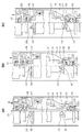
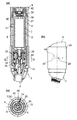
図1(b)に示すように、このシャワー装置1は、水の取り入れ口2を有してホース等を接続する基端コネクタ3と、この基端コネクタ3の下流側に接続され、使用者が把持できる形状の外筒4と、この外筒4の下流に接続されて止水弁および散水口5を設けたヘッド部6とを有する。
As shown in FIG.1 (b), this
外筒4とヘッド部6とはネジ結合によって着脱自在に取り付けられている。
外筒4の内部には、薬剤を収容できる略筒状の薬剤収容部7が内蔵されており、薬剤を使い切った時には外筒4とヘッド部6とを分解して薬剤収容部7を新品に交換することができる。
これにより、シャワー装置1の内部には、流入した水が外筒4と薬剤収容部7との間を通過してヘッド部6の散水口5から吐出される原水流路8と、水の一部が原水流路8から分岐し、薬剤収容部7の内部を通過しながら薬剤を溶出させて、外筒4の下流端付近で原水流路8に合流する混合水流路9とが形成される。
The
The
Thereby, in the
シャワー装置1は、水が原水流路8のみを流れる原水吐出と、水の一部が原水流路8を流れ残部が混合水流路9を流れる混合水吐出とを切り換えるために、流路切換弁を具備している。
この切換弁は、薬剤収容部7の上流側の混合水流路を開閉する収容部上流弁と、薬剤収容部7の下流側の混合水流路を開閉する収容部下流弁と、収容部上流弁および収容部下流弁を操作することができる1つの操作リング10を有している。
The
The switching valve includes a container upstream valve that opens and closes the mixed water flow path upstream of the
図1(b)に示すように、収容部上流弁は、薬剤収容部7の上流端に設けられた弁座11と、この弁座11に水密に当接することができるパッキン12と、弁座11から突出形成されたスペーサ13と、パッキン12に一体に取り付けられてスペーサ13に当接するスペーサ受け14と、スペーサ13およびパッキン12を弁座へ付勢するコイルスプリング15とからなる。
As shown in FIG. 1 (b), the container upstream valve includes a
図5に示すように、弁座11は、薬剤収容部7の上流端(下端)に形成された筒状の部分で、中央に薬剤収容部7の内部に連通する入口を穿設している。
弁座11の周囲からは、2つの三角形状のスペーサ13が上流に向かって突出形成されている。
As shown in FIG. 5, the
Two
図1(b)に示すように、パッキン12は弁座11の入口よりも大径に形成されるとともに弁座11の上流に配置され、弁座11に押し付けられると入口を塞ぐことができる。
また、パッキン12の上流側には、弾性変形によってスペーサ受け14に取り付けられる装着部分が形成されている。
As shown in FIG. 1 (b), the packing 12 is formed larger in diameter than the inlet of the
Further, a mounting portion that is attached to the
図4、図5に示すように、スペーサ受け14は、中央にパッキン12を装着する孔を有する円板から下流側に円筒を延出した形状に形成されている。
スペーサ13に当接するスペーサ受け14の下流端面は、2つの山状部分と谷状部分とが急な斜めの段差で連続した形状に形成されている。円筒の周における山状部分の割合は、谷状部分に比べてかなり小さい。
また、スペーサ受け14は、基端コネクタ3から所定距離離間すると基端コネクタ3に係止して離間を制限する3つの鉤状部16を上流側に突出形成している。
As shown in FIGS. 4 and 5, the
The downstream end face of the
Further, the
図1(b)に示すように、コイルスプリング15は、基端コネクタ3の一部と、スペーサ受け14とに当接して、スペーサ受け14およびパッキン12を弁座11へ付勢する。
As shown in FIG. 1B, the
図1(b)に示すように、収容部下流弁は、薬剤収容部の下流端に設けられた弁座17と、この弁座17に水密に当接することができるパッキン18と、弁座17から突出形成されたスペーサ19と、パッキン18に一体に取り付けられてスペーサ19に当接するスペーサ受け20と、スペーサ受け20およびパッキン18を弁座17へ付勢するコイルスプリング21とからなる。
As shown in FIG. 1 (b), the accommodating portion downstream valve includes a
図4に示すように、弁座17は、薬剤収容部7の下流端(上端)に形成された筒状の部分で、中央に薬剤収容部7の内部に連通する出口を穿設している。
弁座17の周囲からは、2つの三角形状のスペーサ19が下流に向かって突出形成されている。
さらに弁座17の周囲には、周上等間隔に4つの板材22を配置して、板材22の間に混合水が原水流路8に合流するための流路を形成している。
As shown in FIG. 4, the
Two
Further, around the
図1(b)に示すように、パッキン18は弁座17の出口よりも大径に形成されるとともに弁座17の下流に配置され、弁座17に押し付けられると出口を塞ぐことができる。
また、パッキン18の下流側には、弾性変形によってスペーサ受け20に取り付けられる装着部分が形成されている。
As shown in FIG. 1 (b), the packing 18 is formed with a larger diameter than the outlet of the
A mounting portion that is attached to the
図5に示すように、スペーサ受け20は、中央にパッキン18を装着する孔を有する円板から上流側に円筒を延出した形状に形成されている。
スペーサ19に当接するスペーサ受け20の上流端面は、各2つの山状部分と谷状部分とが緩やかな湾曲形状で連続した形状に形成されている。
また、スペーサ受け20は、ヘッド部6から所定距離離間するとヘッド部6に係止して離間を制限する3つの鉤状部分23を下流側に突出形成している。
As shown in FIG. 5, the
The upstream end surface of the
In addition, the
図1(b)に示すように、コイルスプリング21は、ヘッド部6の一部と、スペーサ受け20とに当接して、スペーサ受け20およびパッキン18を弁座17へ付勢する。
As shown in FIG. 1B, the
図1(c)、図3(b)に示すように、外筒4の上流側では、図に示すように、外部に露出した操作リング10がピン24と回転不能に固定され、このピン24が外筒4内部の中継筒体25に回転不能に取り付けられることにより、操作リング10と中継筒体25とが一体になって外筒4に対して回転するようになっている。
外筒4にはピン24を貫通させるピンガイド26が周方向に延設されており、操作リング10の回転可能範囲はこのピンガイド26の範囲によって制限されている。
As shown in FIGS. 1 (c) and 3 (b), on the upstream side of the
A
さらに、図1(d)に示すように、中継筒体25の下流側端部が薬剤収容部7の一部に挟まれて、回転不能に取り付けられているため、操作リング10と薬剤収容部7とも一体になって回転するようになっている。
中継筒体25と薬剤収容部7とがこのように取り付けられることにより、薬剤収容部7を交換しても必ず決まった角度位置で中継筒体25に取り付けることができる。
Further, as shown in FIG. 1 (d), the downstream end of the
By attaching the
このシャワー装置1において、図1に示す操作リング10の回転可能範囲の一端では、混合水吐出となる。
このとき、収容部上流弁では、図6(a)に示すように、スペーサ13がスペーサ受け14の山状部分に当接することにより、コイルスプリング15の付勢力に反してパッキン12が弁座11から離間され、原水流路8の水の一部が入口から薬剤収容部7に流入することができる。
また、収容部下流弁でも、スペーサ19がスペーサ受け20の山状部分に当接することにより、コイルスプリング21の付勢力に反してパッキン18が弁座17から離間され、薬剤収容部7内の水が出口から原水流路8に合流することができる。
In this
At this time, in the accommodating portion upstream valve, as shown in FIG. 6A, the
Further, also in the accommodating portion downstream valve, the packing 19 is separated from the
シャワー装置1の内部では、取り入れ口2から供給された水が原水流路8を通過するとともに、原水流路8の水の一部が混合水流路9に分岐して、薬剤を溶出させる。このため、ヘッド部6の散水口5からは、薬剤を含有する混合水が吐出される。
Inside the
操作リング10および薬剤収容部7を混合水吐出の位置から少し回転させると、図2に示す中間位置となる。
このとき、収容部上流弁では、図6(b)に示すように、スペーサ13がスペーサ受け14の急な段差を通過して谷状部分に当接するため、コイルスプリング15の付勢力によってパッキン12が弁座11に押し付けられ、薬剤収容部7の入口が塞がれる。
収容部下流弁では、スペーサ19がスペーサ受け20の山状部分から谷状部分へと連続する緩やかな湾曲面に当接するため、出口はパッキン18によって塞がれないが、コイルスプリング21の付勢力によってパッキン18が弁座17に徐々に近づき、薬剤収容部7の出口から原水流路8に合流する流路が徐々に狭くなっていく。
When the
At this time, as shown in FIG. 6B, in the accommodating portion upstream valve, the
In the accommodating portion downstream valve, since the
シャワー装置1の内部では、原水流路8の水が入口から薬剤収容部7に流入することはできないが、薬剤収容部7内の水は出口から原水流路8に合流することができる。このため、ヘッド部6の散水口5からは、微量の薬剤を含有する混合水が吐出される。
In the
操作リング10および薬剤収容部7をこの中間位置から回転可能範囲の反対端まで回動させると、図3に示す原水吐出となる。
このとき、収容部上流弁では、図6(c)に示すように、スペーサ13がスペーサ受け14の谷状部分に当接しているため、薬剤収容部7の入口がパッキン12によって塞がれている。
収容部下流弁では、スペーサ19がスペーサ受け20の谷状部分に当接するため、コイルスプリング21の付勢力によってパッキン18が弁座17に押し付けられ、薬剤収容部7の出口が塞がれる。
When the
At this time, in the container upstream valve, as shown in FIG. 6C, the
In the accommodating portion downstream valve, since the
シャワー装置1の内部では、混合水流路9が閉鎖され、水が薬剤収容部7の外周の原水流路8のみを流れるため、ヘッド部6の散水口5からは、薬剤を含有しない原水が吐出される。
Inside the
操作リング10および薬剤収容部7を原水吐出の位置から混合水吐出の位置まで逆回転させると、収容部上流弁ではスペーサ13がスペーサ受け14の斜めの段差に沿って山状部分に到達し、コイルスプリング15の付勢力に反してパッキン12が弁座11から離間させられる。
収容部下流弁でもスペーサ19がスペーサ受け20の緩やかな湾曲形状に沿って山状部分に到達するため、コイルスプリング21の付勢力に反してパッキン18が弁座17から離間させられる。
したがって、ヘッド部6の散水口5からは、薬剤を含有する混合水が吐出される。
When the
Even in the accommodating portion downstream valve, the
Therefore, mixed water containing a medicine is discharged from the
第一実施形態のシャワー装置1では、図6(a)(c)に示すように、収容部上流弁と収容部下流弁とが、1つの操作部材である操作リング10の回転動作に連動して混合水流路9を開閉することにより、原水吐出時に混合水が薬剤収容部7から漏出することがなく、使用者が1つの操作リング10を操作するだけで原水吐出と混合水吐出とを確実に切り換えることができる。
また、原水吐出時に混合水が薬剤収容部7から漏出することがないため、薬剤の無駄な消費を防止して薬剤収容部7の交換寿命を長期化することができる。
In the
In addition, since the mixed water does not leak from the
また、図6(b)に示すように、流路切換弁を混合水吐出の位置から原水吐出の位置まで移行する間に、収容部上流弁が弁閉であり収容部下流弁が弁開である中間位置を設けたことにより、薬剤収容部7内の水が収容部下流弁から原水流路8へ流出して水圧を軽減させるため、混合水流路9の水流を遮断することにより薬剤収容部7内の水圧が急上昇することがなく、水圧による薬剤収容部7の破損を防止することができる。
さらに、薬剤収容部7内の水圧が急上昇しないため、混合水吐出から原水吐出への切り換え操作に必要な力を小さくすることができる。
In addition, as shown in FIG. 6B, while the flow path switching valve is moved from the mixed water discharge position to the raw water discharge position, the storage unit upstream valve is closed and the storage unit downstream valve is open. By providing a certain intermediate position, the water in the
Furthermore, since the water pressure in the
また、流路切換弁の操作リング10を混合水吐出の位置から原水吐出の位置まで移行するのに連動して、収容部下流弁の開放度が徐々に減少するようにしたことにより、負圧を発生させるため、薬剤収容部7内の混合水を流出させて、効果的に薬剤収容部7内の水圧を軽減させることができる。
また、収容部下流弁でもスペーサ19がスペーサ受け20の緩やかな湾曲形状に沿って移動し、パッキン18を徐々に上げ下げするため、収容部下流弁を操作するのに必要な力を小さくすることができる。
In addition, the degree of opening of the storage unit downstream valve gradually decreases in conjunction with the transition of the
Further, the
図1(b)に示すように、ヘッド部6には、使用者が水の吐出と停止とを切り換えることができる止水弁を設けている。
この止水弁は、ヘッド部6の流路中に配置された弁軸27と、弁軸27に取り付けられてシャワー装置1の背部側に露出した吐水ボタン28と、弁軸27に取り付けられてシャワー装置1の腹部側に露出した止水ボタン29とからなる。
As shown in FIG. 1B, the
The water stop valve is attached to the
弁軸27は、ヘッド部6の流路と平行な弁軸流路30を穿設されており、背部腹部方向に移動可能にヘッド部6に収容されている。
背部の吐水ボタン28を押し込むと、弁軸27の弁軸流路30がヘッド部6の流路に合致して、原水または混合水を散水口5から吐出することができる。
腹部の止水ボタン29を押し込むと、ヘッド部6の流路が弁軸27によって塞がれ、散水口5からの吐出を停止することができる。
The
When the
When the abdomen
このような止水弁を設けたことにより、使用者が手元で容易に水の吐出と停止とを切り換えることができる。
また、流路切換弁の下流に止水弁を設けたことにより、万が一薬剤収容部7や流路切換弁が破損して、混合水が常時下流に漏れ出すようになっても、止水ボタン29を押し込んで吐出を停止することによって、混合水の匂いが外部に漏れることを防止することができる。
By providing such a water stop valve, the user can easily switch between discharging and stopping water at hand.
In addition, by providing a water stop valve downstream of the flow path switching valve, even if the
止水ボタン29を押し込んで吐出を停止すると、止水弁の上流では水撃が生じることがある。
しかし、原水吐出のときには、中継筒体25と鉤状部分23が係止されるヘッド部6の一部とによって薬剤収容部7の上流下流方向の動きが制限されるとともに、コイルスプリング15がパッキン12を弁座11に押圧し、コイルスプリング21がパッキン18を弁座17に押圧しているので、水撃によって薬剤収容部7の閉鎖状態が損なわれるのを防止することができる。
When the
However, when the raw water is discharged, the movement of the
図1から図3に示すように、このシャワー装置1には、使用者が原水吐出と混合水吐出との切り換えを視認することができるように表示機構を設けている。
この表示機構は、シャワー装置1の外面を形成するケーシングの一部である外筒4に形成した表示窓31と、薬剤収容部7の外面に形成した2つの表示32a、32bとからなる。
As shown in FIGS. 1 to 3, the
The display mechanism includes a
表示窓31は、外筒4の周面に形成した開口に樹脂等からなる透明な板材を嵌め込み、接着剤による接着や超音波溶着等の溶着で固定して形成される。
図4、図5に示すように、薬剤収容部7の外面のうち、混合水吐出の位置で表示窓31に面する部分には、円形の突起や「混合水」の文字等の混合水表示32aを形成している。
また、薬剤収容部7の外面のうち、原水吐出の位置で表示窓31に面する部分には四角形の突起や「原水」の文字等の原水表示32bを形成している。
なお、表示32a、32bには、突起、刻印、印刷その他のあらゆる表示を採用してよい。
The
As shown in FIGS. 4 and 5, on the outer surface of the
Further, a
In addition, as the
これにより、混合水吐出の位置では使用者が表示窓31から混合水表示32aを視認し(図1(a))、原水吐出の位置では使用者が表示窓31から原水表示32bを視認して(図3(a))、混合水と原水との切り換えを把握することができる。
また、表示32a、32bがシャワー装置1の内部の薬剤収容部7に形成されているため、使用者の手や他の物によって剥がれるおそれがない。
さらに、表示32a、32bが原水流路8中に配置されているため、原水の流れによって自動的に洗浄し、汚れを付着しにくくすることができる。
As a result, the user visually recognizes the
Moreover, since the
Furthermore, since the
また、交換部品である薬剤収容部7に表示を設けたことにより、表示32a、32bの初期不良や後発的な破損があっても、薬剤収容部7を交換することにより比較的容易に且つ低コストで適切な表示機構に交換することができる。
さらに、交換部品である薬剤収容部7に表示を設けたことにより、薬剤収容部7の薬剤の種類に応じて、異なる混合水表示32aを設けることができる。
たとえば、オレンジの芳香剤を収容した薬剤収容部7の混合水表示32aには「オレンジ」の文字等を形成し、レモンの芳香剤を収容した薬剤収容部7の混合水表示32aには「レモン」の文字等を形成して、区別できるようにする。
これにより、混合水による効果をより詳細に使用者に知らせることができる。
In addition, by providing a display on the
Furthermore, by providing a display on the
For example, a letter “orange” or the like is formed on the
Thereby, the effect by mixed water can be notified to a user in detail.
なお、第一実施形態では、混合水吐出時にも水の一部が原水流路8(薬剤収容部7の外周)を通過するが、混合水吐出時には薬剤収容部7の外周の流路が閉鎖され、水が薬剤収容部7の内部のみを通過する構造としてもよい。
In the first embodiment, a part of the water also passes through the raw water flow path 8 (the outer periphery of the medicine container 7) even when the mixed water is discharged, but the outer periphery of the
また、薬剤収容部7は薬剤を使い切った後に新品と交換するカートリッジとして形成されているが、空になった薬剤収容部7に薬剤を補充して再度使用する非交換部品としてもよい。
Moreover, although the
<第二実施形態>
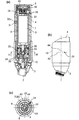
第二実施形態のシャワー装置1では、第一実施形態と異なる構成の流路切換弁を設けている。
図7(a)に示すように、収容部上流弁は、基端コネクタ3に固定され外筒4の内部に配置された弁座33と、この弁座33に水密に当接することができるパッキン34と、パッキン34を弁座33へ付勢するコイルスプリング35と、薬剤収容部7から上流に突出形成されたスペーサ36とからなる。
<Second embodiment>
In the
As shown in FIG. 7A, the accommodating portion upstream valve includes a
弁座33は、薬剤収容部7の上流の原水流路8中に配置される部品であって、中央に弁座流路を穿設している。
パッキン34は弁座33の入口よりも大径に形成されるとともに弁座33の上流に配置され、弁座33に押し付けられると弁座流路を塞ぐことができる。
コイルスプリング35は、基端コネクタ3の一部と、パッキン34とに当接して、パッキン34を弁座33へ付勢する。
The
The packing 34 has a larger diameter than the inlet of the
The
図10に示すように、スペーサ36は、薬剤収容部7から上流に突出形成された筒形状の部分で、弁座流路よりも細いため、弁座流路を通ってパッキン34を押すことができる。
スペーサ36の内部は、薬剤収容部7の内部に連通している。
スペーサ36の先端付近には、薬剤収容部7への入口となる複数の切り欠きが形成されている。
As shown in FIG. 10, the
The inside of the
Near the tip of the
図7(a)に示すように、収容部下流弁は、薬剤収容部7の下流端に設けられた弁座37と、この弁座37に水密に当接することができるパッキン38と、パッキン38に一体に取り付けられるスペーサ39と、スペーサ39およびパッキン38を弁座へ付勢するコイルスプリング40とからなる。
As shown in FIG. 7A, the accommodating portion downstream valve includes a
図10に示すように、弁座37は、薬剤収容部7の下流端(上端)に形成された筒状の部分で、中央に薬剤収容部7の内部に連通する出口を穿設している。
弁座37の周端では、スペーサ39の凸部に合致する三角形状のスペーサ受け溝41が周上2箇所に凹設されている。
As shown in FIG. 10, the
At the circumferential end of the
図7(a)に示すように、パッキン38は弁座37の出口よりも大径に形成されるとともに弁座37の下流に配置され、弁座37に押し付けられると出口を塞ぐことができる。
また、パッキン38の下流側には、弾性変形によってスペーサ39に取り付けられる装着部分が形成されている。
As shown in FIG. 7A, the packing 38 is formed with a larger diameter than the outlet of the
A mounting portion that is attached to the
図10に示すように、スペーサ39は、中央にパッキン38を装着する孔を有する円板から上流側に円筒を延出した形状に形成されている。
スペーサ39の上流端面からは、スペーサ受け溝41に合致する三角形状の凸部が上流に向かって突出形成されている。
また、スペーサ39は、ヘッド部6から所定距離離間するとヘッド部6に係止して離間を制限する3つの鉤状部分42を下流側に突出形成している。スペーサ39は、ヘッド部6に対して回転しないように固定されている。
As shown in FIG. 10, the
From the upstream end surface of the
Further, the
図7(a)に示すように、コイルスプリング40は、ヘッド部6の一部と、スペーサ39とに当接して、スペーサ39およびパッキン38を弁座37へ付勢する。
As shown in FIG. 7A, the
外筒4の上流側では、図7(a)に示すように、外部に露出した操作リング10が外筒4に対して回転可能に取り付けられている。
図7(b)(c)に示すように、操作リング10は、ピン24と回転不能に取り付けられている。このピン24は、外筒4の周方向に延設された第一ピンガイド43を貫通し、外筒4内部の中継筒体25の外周面に斜めに刻設された第二ピンガイド44に係合している。
操作リング10を外筒4に対して回転させると、ピン24が第一ピンガイド43および第二ピンガイド44をスライドする(図7(b)、図8(b)、図9(b))。操作リング10の回転可能範囲は、第一ピンガイド43の範囲によって制限されている。
On the upstream side of the
As shown in FIGS. 7B and 7C, the
When the
操作リング10と中継筒体25とは互いに回転することができ、中継筒体25と外筒4とも互いに回転することができる。
また、図7(d)に示すように、中継筒体25の上流側端部が薬剤収容部7の一部に挟まれて、回転不能に取り付けられているため、操作リング10と薬剤収容部7とも一体になって回転するようになっている。
中継筒体25と薬剤収容部7とがこのように取り付けられることにより、薬剤収容部7を交換しても必ず決まった角度位置で中継筒体25に取り付けることができる。
The
Further, as shown in FIG. 7 (d), since the upstream end of the
By attaching the
このシャワー装置1においても、図7に示す操作リング10の回転可能範囲の一端では、混合水吐出となる。
このとき、収容部上流弁では、コイルスプリング35の付勢力に反してスペーサ36がパッキン34を押し下げ、パッキン34が弁座33から離間され、原水流路8の水の一部がスペーサ39の切り欠きから薬剤収容部7に流入することができる。
また、収容部下流弁でも、スペーサ39が弁座37のスペーサ受け溝41以外の部分に当接することにより、コイルスプリング35の付勢力に反してパッキン34が弁座33から離間され、薬剤収容部7内の水が出口から原水流路8に合流することができる。
このとき、ピン24は、斜めに形成された第二ピンガイド44の上端に位置している(図7(b))。
Also in this
At this time, in the accommodating portion upstream valve, the
Further, also in the accommodating portion downstream valve, the
At this time, the
シャワー装置1の内部では、取り入れ口2から供給された水が原水流路8を通過するとともに、原水流路8の水の一部が分岐して薬剤収容部7に流入し、薬剤を溶出させて、原水流路8に合流する。このため、ヘッド部6の散水口5からは、薬剤を含有する混合水が吐出される。
Inside the
操作リング10および薬剤収容部7を混合水吐出の位置から少し回転させると、図8に示す中間位置となる。
中間位置ではピン24が第一ピンガイド43および第二ピンガイド44をスライドするが、第一ピンガイド43が周方向に延設されているのに対し、第二ピンガイド44は周方向に対して斜めに延設されている。このため、ピン24が第二ピンガイド44を下方にスライドすると、中継筒体25および薬剤収容部7が、外筒4および操作リング10に対して徐々に上方(下流側)に移動する(図8(b))。
When the
At the intermediate position, the
収容部上流弁では、スペーサ36が徐々に上方に移動することにより、パッキン34が徐々に弁座33に近づいて、原水流路8から薬剤収容部7に流入する流路が徐々に狭くなっていき、最終的には弁座33がパッキン34によって塞がれる。
収容部下流弁では、スペーサ39が弁座37のスペーサ受け溝41以外の部分に当接し続けているため、コイルスプリング40の付勢力に反してパッキン38が弁座37から離間され続けている。
In the storage unit upstream valve, the
In the accommodating portion downstream valve, the
シャワー装置1の内部では、原水流路8の水が薬剤収容部7に入口から流入することはできないが、薬剤収容部7内の水は出口から原水流路8に合流することができる。このため、ヘッド部6の散水口5からは、微量の薬剤を含有する混合水が吐出される。
In the
操作リング10をこの中間位置から回転可能範囲の反対端まで回動させると、図9に示す原水吐出となる。
中間位置でピン24は第二ピンガイド44の下端に到達している(図8(b))ため、中間位置から原水吐出の位置まで操作リング10を回転させる間は、ピン24が第一ピンガイド43をスライドし、中継筒体25および薬剤収容部7が操作リング10と一体になって外筒4(シャワー装置1)に対して回転する。
When the
Since the
原水吐出の位置において、収容部上流弁では、弁座33がパッキン34によって塞がれている。
収容部下流弁では、スペーサ39が回転によって弁座37のスペーサ受け溝41に合致し、コイルスプリング40の付勢力によってパッキン38が弁座37に押し付けられ、薬剤収容部7の出口が塞がれる。
At the raw water discharge position, the
In the accommodating portion downstream valve, the
シャワー装置1の内部では、水が薬剤収容部7の外周の原水流路8のみを流れ、ヘッド部の散水口からは、薬剤を含有しない原水が吐出される。
Inside the
操作リング10および薬剤収容部7を原水吐出の位置から混合水吐出の位置まで逆回転させると、ピン24が第一ピンガイド43および第二ピンガイド44を逆向きにスライドすることにより、中継筒体25および薬剤収容部7を下方(上流側)へ移動させるため、収容部上流弁ではスペーサ36がコイルスプリング35の付勢力に反してパッキン34を弁座33から離間させる。
収容部下流弁ではスペーサ39が弁座37に対して回転しスペーサ受け溝41からずれて、コイルスプリング40の付勢力に反してパッキン38が弁座37から離間させられる。
したがって、ヘッド部6の散水口5からは、薬剤を含有する混合水が吐出される。
When the
In the accommodating portion downstream valve, the
Therefore, mixed water containing a medicine is discharged from the
第二実施形態のシャワー装置1でも、図8(a)に示すように、流路切換弁を混合水吐出の位置から原水吐出の位置まで移行する間に、収容部上流弁を閉鎖させて収容部下流弁を開放させる位置を設けたことにより、薬剤収容部7内の水が収容部下流弁から原水流路8へ流出して水圧を軽減させるため、混合水流路9の水流を遮断することにより薬剤収容部内7の水圧が急上昇することがなく、水圧による薬剤収容部7の破損を防止することができる。
さらに、薬剤収容部7内の水圧が急上昇しないため、混合水吐出から原水吐出への切り換え操作に必要な力を小さくすることができる。
Also in the
Furthermore, since the water pressure in the
また、第二実施形態で混合水吐出から原水吐出へ切り換えると、薬剤収容部7が外筒4に対して回転するとともに上下方向に移動するため、図10に示すように、混合水表示32aと原水表示32bとを互いに斜めに配置している。
これにより、混合水吐出時には混合水表示32aが表示窓31に面し(図7(a))、原水吐出時には原水表示32bが表示窓31に面する(図9(a))。
Further, when switching from the mixed water discharge to the raw water discharge in the second embodiment, the
Thus, the
1 シャワー装置
2 取り入れ口
3 基端コネクタ
4 外筒
5 散水口
6 ヘッド部
7 薬剤収容部
8 原水流路
9 混合水流路
10 操作リング
11 弁座(収容部上流弁)
12 パッキン(収容部上流弁)
13 スペーサ(収容部上流弁)
14 スペーサ受け(収容部上流弁)
15 コイルスプリング(収容部上流弁)
16 鉤状部分(収容部上流弁)
17 弁座(収容部下流弁)
18 パッキン(収容部下流弁)
19 スペーサ(収容部下流弁)
20 スペーサ受け(収容部下流弁)
21 コイルスプリング(収容部下流弁)
22 板材
23 鉤状部分(収容部下流弁)
24 ピン
25 中継筒体
26 ピンガイド
27 弁軸
28 吐水ボタン
29 止水ボタン
30 弁軸流路
31 表示窓
32a (混合水)表示
32b (原水)表示
33 弁座(収容部上流弁)
34 パッキン(収容部上流弁)
35 コイルスプリング(収容部上流弁)
36 スペーサ(収容部上流弁)
37 弁座(収容部下流弁)
38 パッキン(収容部下流弁)
39 スペーサ(収容部下流弁)
40 コイルスプリング(収容部下流弁)
41 スペーサ受け溝(収容部下流弁)
42 鉤状部分
43 第一ピンガイド
44 第二ピンガイド
DESCRIPTION OF
12 Packing (housing upstream valve)
13 Spacer (Upstream valve in the housing)
14 Spacer receiver (upstream valve in housing)
15 Coil spring (upstream valve of housing part)
16 Hook-shaped part (upstream valve of the housing part)
17 Valve seat (accommodating section downstream valve)
18 Packing (Housing downstream valve)
19 Spacer (Downstream valve of the receiving part)
20 Spacer receptacle (downstream valve in housing)
21 Coil spring (downstream valve in housing)
22
24
34 Packing (upstream valve in the housing)
35 Coil spring (upstream valve in the housing)
36 Spacer (Upstream valve in the housing)
37 Valve seat (receiving section downstream valve)
38 Packing (Housing downstream valve)
39 Spacer (Downstream valve in the housing)
40 Coil spring (downstream valve for housing)
41 Spacer receiving groove (reservoir downstream valve)
42 Hook-shaped
Claims (4)
上記薬剤収容部の上流側の上記混合水流路を開閉する収容部上流弁と、上記薬剤収容部の下流側の上記混合水流路を開閉する収容部下流弁とを設け、
上記収容部上流弁と上記収容部下流弁とが、1つの操作部材の動作に連動して上記混合水流路を開閉することを特徴とするシャワー装置。 A medicine container containing a medicine, a raw water flow path in which water does not pass through the medicine storage part and flows to the sprinkling port, and water branches from the raw water flow path and passes through the inside of the medicine containing part. Elution and forming a mixed water flow path that merges with the raw water flow path,
A container upstream valve that opens and closes the mixed water channel upstream of the drug container; and a container downstream valve that opens and closes the mixed water channel downstream of the drug container;
The shower device, wherein the storage unit upstream valve and the storage unit downstream valve open and close the mixed water flow path in conjunction with the operation of one operation member.
上記薬剤収容部がシャワー装置の外面を形成するケーシングに収容され、1つの操作部材の操作に連動して上記ケーシングに対して動くとともに上記混合水流路が開閉され、
上記ケーシングの一部に透明な表示窓を設け、内部の上記薬剤収容部を外部から視認できるようにし、
且つ、上記薬剤収容部の外面のうち、上記混合水流路を開放させたときに上記表示窓に面する部分、および上記混合水流路を閉鎖させたときに上記表示窓に面する部分に異なる表示を形成したことを特徴とするシャワー装置。 A medicine container containing a medicine, a raw water flow path in which water does not pass through the medicine storage part and flows to the sprinkling port, and water branches from the raw water flow path and passes through the inside of the medicine containing part. Eluting and forming a mixed water flow path that joins the raw water flow path,
The medicine container is housed in a casing that forms the outer surface of the shower device, moves with respect to the casing in conjunction with the operation of one operation member, and the mixed water flow path is opened and closed,
A transparent display window is provided in a part of the casing so that the internal medicine container can be seen from the outside.
In addition, different displays on the outer surface of the medicine container include a portion facing the display window when the mixed water channel is opened and a portion facing the display window when the mixed water channel is closed. A shower device, characterized in that it is formed.
Priority Applications (1)
| Application Number | Priority Date | Filing Date | Title |
|---|---|---|---|
| JP2013064059A JP5778710B2 (en) | 2013-03-26 | 2013-03-26 | Shower equipment |
Applications Claiming Priority (1)
| Application Number | Priority Date | Filing Date | Title |
|---|---|---|---|
| JP2013064059A JP5778710B2 (en) | 2013-03-26 | 2013-03-26 | Shower equipment |
Publications (2)
| Publication Number | Publication Date |
|---|---|
| JP2014188041A JP2014188041A (en) | 2014-10-06 |
| JP5778710B2 true JP5778710B2 (en) | 2015-09-16 |
Family
ID=51835018
Family Applications (1)
| Application Number | Title | Priority Date | Filing Date |
|---|---|---|---|
| JP2013064059A Active JP5778710B2 (en) | 2013-03-26 | 2013-03-26 | Shower equipment |
Country Status (1)
| Country | Link |
|---|---|
| JP (1) | JP5778710B2 (en) |
Families Citing this family (2)
| Publication number | Priority date | Publication date | Assignee | Title |
|---|---|---|---|---|
| KR101712799B1 (en) * | 2013-12-24 | 2017-03-08 | 주식회사 피코그램 | eruption quantity control device using underwater turning cartridge |
| CN109394044A (en) * | 2018-12-13 | 2019-03-01 | 东莞市倍益清环保科技有限公司 | A kind of Storage Box and shower |
Family Cites Families (2)
| Publication number | Priority date | Publication date | Assignee | Title |
|---|---|---|---|---|
| JPH0681389U (en) * | 1993-04-30 | 1994-11-22 | 巍 藤 | Cosmetic elution device |
| JP2006174891A (en) * | 2004-12-21 | 2006-07-06 | Toto Ltd | Shower head |
-
2013
- 2013-03-26 JP JP2013064059A patent/JP5778710B2/en active Active
Also Published As
| Publication number | Publication date |
|---|---|
| JP2014188041A (en) | 2014-10-06 |
Similar Documents
| Publication | Publication Date | Title |
|---|---|---|
| US11179231B2 (en) | Oral irrigator handle for use with oral agent | |
| US8678244B2 (en) | Soap dispensing units with anti-drip valve | |
| US20090000024A1 (en) | Dispensing system and method, and injector therefor | |
| US11692337B2 (en) | Bidet washing apparatus with disinfectant wash feature | |
| JP5778710B2 (en) | Shower equipment | |
| US11879243B2 (en) | Bidet washing apparatus with disinfectant wash feature | |
| US11814834B2 (en) | Bidet washing apparatus with disinfectant wash feature | |
| WO2006122368A1 (en) | Valve structures for liquid dispensing | |
| US11666931B2 (en) | Inline shower device | |
| US20230278051A1 (en) | Inline shower device | |
| EP2242564B1 (en) | Water mixer applicable to water dispensing units, particularly of sanitary fittings, for adding water-soluble substances to the water | |
| US20230100608A1 (en) | Bidet washing apparatus with disinfectant wash feature | |
| JP2014064745A (en) | Water discharge head and water faucet device provided with the same | |
| CN214484702U (en) | Nozzle storage structure and oral cavity flushing device | |
| JP2010029857A (en) | Sprinkler nozzle | |
| US10220360B1 (en) | Liquid mixing apparatus | |
| US20220056678A1 (en) | Inline dispensing device | |
| CN216041528U (en) | Faucet with integrated soap dispenser | |
| EP4273335A1 (en) | Bidet washing apparatus with disinfectant wash feature | |
| JP4498055B2 (en) | Attachment for mixing | |
| US20240060282A1 (en) | Bidet washing apparatus with disinfectant wash feature | |
| CN215568127U (en) | Faucet and faucet using same | |
| EP4159322A1 (en) | Bidet washing apparatus with disinfectant wash feature | |
| JP4169684B2 (en) | Attachment for mixing | |
| TWM599872U (en) | Safety switch |
Legal Events
| Date | Code | Title | Description |
|---|---|---|---|
| A977 | Report on retrieval |
Free format text: JAPANESE INTERMEDIATE CODE: A971007 Effective date: 20150109 |
|
| A131 | Notification of reasons for refusal |
Free format text: JAPANESE INTERMEDIATE CODE: A131 Effective date: 20150127 |
|
| TRDD | Decision of grant or rejection written | ||
| A01 | Written decision to grant a patent or to grant a registration (utility model) |
Free format text: JAPANESE INTERMEDIATE CODE: A01 Effective date: 20150707 |
|
| A61 | First payment of annual fees (during grant procedure) |
Free format text: JAPANESE INTERMEDIATE CODE: A61 Effective date: 20150709 |
|
| R150 | Certificate of patent or registration of utility model |
Ref document number: 5778710 Country of ref document: JP Free format text: JAPANESE INTERMEDIATE CODE: R150 |
|
| R250 | Receipt of annual fees |
Free format text: JAPANESE INTERMEDIATE CODE: R250 |
|
| R250 | Receipt of annual fees |
Free format text: JAPANESE INTERMEDIATE CODE: R250 |
|
| R250 | Receipt of annual fees |
Free format text: JAPANESE INTERMEDIATE CODE: R250 |
|
| R250 | Receipt of annual fees |
Free format text: JAPANESE INTERMEDIATE CODE: R250 |
|
| R250 | Receipt of annual fees |
Free format text: JAPANESE INTERMEDIATE CODE: R250 |
|
| R250 | Receipt of annual fees |
Free format text: JAPANESE INTERMEDIATE CODE: R250 |