JP5778317B1 - Mode-to-mode power ratio measuring method, power-ratio measuring device, and mode-to-mode power ratio measuring system - Google Patents
Mode-to-mode power ratio measuring method, power-ratio measuring device, and mode-to-mode power ratio measuring system Download PDFInfo
- Publication number
- JP5778317B1 JP5778317B1 JP2014114635A JP2014114635A JP5778317B1 JP 5778317 B1 JP5778317 B1 JP 5778317B1 JP 2014114635 A JP2014114635 A JP 2014114635A JP 2014114635 A JP2014114635 A JP 2014114635A JP 5778317 B1 JP5778317 B1 JP 5778317B1
- Authority
- JP
- Japan
- Prior art keywords
- mode
- power ratio
- light
- optical fiber
- procedure
- Prior art date
- Legal status (The legal status is an assumption and is not a legal conclusion. Google has not performed a legal analysis and makes no representation as to the accuracy of the status listed.)
- Active
Links
Images


Landscapes
- Testing Of Optical Devices Or Fibers (AREA)
- Optical Communication System (AREA)
Abstract
【課題】本発明は、光ファイバにおいて生じた導波型音響波ブリルアン散乱による散乱光の周波数特性を測定し、該周波数特性において光ファイバ中を伝搬可能な所望の2つの伝搬モードに対応する変調量を比較することにより、当該伝搬モード間のパワー比を算出することを目的とする。【解決手段】本発明に係るモード間パワー比測定方法では、入射光から導波型音響波ブリルアン散乱による偏波変調成分を抽出する偏光手順と、偏光手順で抽出した偏波変調成分を有する入射光を受光し電気信号に変換する受光手順と、受光手順において変換した電気信号から偏波変調成分を測定するスペクトル測定手順と、各伝搬モードに対応する偏波変調成分を互いに比較し、数モード光ファイバを伝搬する伝搬モード間のパワーの比率である伝搬モード間パワー比を算出する算出手順と、を順に行う。【選択図】図1The present invention measures the frequency characteristics of scattered light due to guided-wave acoustic Brillouin scattering generated in an optical fiber, and modulates the frequency characteristics corresponding to two desired propagation modes capable of propagating in the optical fiber. The purpose is to calculate the power ratio between the propagation modes by comparing the quantities. In an inter-mode power ratio measurement method according to the present invention, a polarization procedure for extracting a polarization modulation component by guided acoustic Brillouin scattering from incident light, and an incidence having a polarization modulation component extracted by the polarization procedure. A light reception procedure for receiving light and converting it into an electrical signal, a spectrum measurement procedure for measuring the polarization modulation component from the electrical signal converted in the light reception procedure, and the polarization modulation component corresponding to each propagation mode are compared with each other, and several modes A calculation procedure for calculating a power ratio between propagation modes, which is a ratio of power between propagation modes propagating through the optical fiber, is sequentially performed. [Selection] Figure 1
Description
本発明は、光ファイバの光学特性測定方法に関し、モード多重光ファイバ伝送における光ファイバに対するモード間パワー比測定方法、パワー比測定装置及びモード間パワー比測定システムに関する。 The present invention relates to a method for measuring optical characteristics of an optical fiber, and relates to a method for measuring a power ratio between modes for an optical fiber in a mode multiplexed optical fiber transmission, a power ratio measuring device, and a power ratio measuring system between modes.
複数のコア領域を有するマルチコア光ファイバや複数の伝搬モードを伝搬可能な数モード光ファイバが、空間多重技術を用いることによる飛躍的な伝送容量拡大に向け、活発に検討されている。特に複数の伝搬モードを用いたモード多重伝送は、伝搬可能なモード数分だけ伝送容量を向上させることができることから、新たな大容量伝送方式として注目を集めている。 A multi-core optical fiber having a plurality of core regions and a number mode optical fiber capable of propagating a plurality of propagation modes have been actively studied for a dramatic increase in transmission capacity by using a spatial multiplexing technique. In particular, mode multiplex transmission using a plurality of propagation modes has been attracting attention as a new large-capacity transmission system because the transmission capacity can be improved by the number of modes that can be propagated.
ここでモード多重伝送では、光ファイバ伝搬中や、光ファイバ中の接続点において、またモード合分波器等に代表される複数のモードに対して動作可能なデバイスにおいて生じる、伝搬モード間のモード間結合が伝送特性に大きく影響する。接続点等において各伝搬モードがどの程度励振されているかを測定するためには、一般的に受光側においてモード合分波器を用いて伝搬モードを分離し、各伝搬モードの受光パワーを比較することによって得ることができる。 Here, in mode multiplex transmission, modes between propagation modes that occur during propagation in optical fibers, at connection points in optical fibers, and in devices that can operate for multiple modes such as mode multiplexers / demultiplexers. Intercoupling greatly affects transmission characteristics. In order to measure how much each propagation mode is excited at the connection point, etc., the propagation mode is generally separated using a mode multiplexer / demultiplexer on the light receiving side, and the received light power of each propagation mode is compared. Can be obtained.
この場合、測定できる励振比の下限はモード合分波器の性能に左右されてしまい、モード合分波器で生じるモード間クロストーク以下の値は測定できない。そのため非特許文献1のように、出力光の電界分布における時間変動を微小な範囲ごとに測定することにより、伝搬モード間のパワー比を測定する方法が提案されている。 In this case, the lower limit of the excitation ratio that can be measured depends on the performance of the mode multiplexer / demultiplexer, and a value less than the crosstalk between modes generated in the mode multiplexer / demultiplexer cannot be measured. Therefore, as in Non-Patent Document 1, a method for measuring a power ratio between propagation modes by measuring a time variation in an electric field distribution of output light for each minute range has been proposed.
モード合分波器を用いる場合、上述の通り伝搬モードの分離の際にも合分波器内でモード間結合が生じるため、合分波器のモード間クロストーク以下の値は測定できないという課題があった。また非特許文献1の方法では光ファイバの出射端においてコア径の小さな光ファイバにより電界強度をスキャンするため、光ファイバのコア径が小さなものでは測定が困難であり、さらには微小な範囲ごとに受光パワー時間変動を測定するため、測定系が非常に煩雑となり長時間の測定が必要となる、といった課題があった。 When a mode multiplexer / demultiplexer is used, inter-mode coupling occurs in the multiplexer / demultiplexer even when the propagation modes are separated as described above, so that a value below the crosstalk between modes of the multiplexer / demultiplexer cannot be measured. was there. In the method of Non-Patent Document 1, since the electric field strength is scanned with an optical fiber having a small core diameter at the output end of the optical fiber, measurement is difficult when the optical fiber has a small core diameter. In order to measure the variation of the received light power time, there is a problem that the measurement system becomes very complicated and a long time measurement is required.
前記課題を解決するために、本発明は、複数のモードを伝搬可能な数モード光ファイバを対象とし、該光ファイバにおいて生じた導波型音響波ブリルアン散乱による散乱光の周波数特性を測定し、該周波数特性において光ファイバ中を伝搬可能な所望の2つの伝搬モードに対応する変調量を比較することにより、当該伝搬モード間のパワー比を求めることを目的とする。 In order to solve the above problems, the present invention is directed to a number mode optical fiber capable of propagating a plurality of modes, and measures the frequency characteristics of scattered light caused by guided acoustic Brillouin scattering generated in the optical fiber. An object of the present invention is to obtain a power ratio between the propagation modes by comparing modulation amounts corresponding to two desired propagation modes capable of propagating in the optical fiber in the frequency characteristics.
上記目的を達成するため、本発明では、光ファイバ中で生じる導波型音響波ブリルアン散乱特性が伝搬モードごとに異なる周波数特性を有することを利用し、伝搬モードに対応する周波数成分の電力を比較する。 In order to achieve the above object, the present invention makes use of the fact that the guided acoustic Brillouin scattering characteristics generated in an optical fiber have different frequency characteristics for each propagation mode, and compares the power of frequency components corresponding to the propagation modes. To do.
具体的には、本発明に係るモード間パワー比測定方法は、
少なくとも1つの光源から光波が数モード光ファイバに入射され、前記数モード光ファイバを介して入射された光波から導波型音響波ブリルアン散乱による偏波変調成分を前記複数の入射光ごとに抽出する偏光手順と、
前記偏光手順で抽出した前記偏波変調成分を有する入射光を受光し、受光した入射光ごとに電気信号に変換する受光手順と、
前記受光手順において変換した各電気信号から前記偏波変調成分を測定するスペクトル測定手順と、
前記スペクトル測定手順で測定した電気信号に対応する偏波変調成分を互いに比較し、前記数モード光ファイバを伝搬した伝搬モード間のパワーの比率である伝搬モード間パワー比を算出する算出手順と、を順に行う。
Specifically, the inter-mode power ratio measuring method according to the present invention is:
Light waves from at least one light source are incident on a few-mode optical fiber, and a polarization-modulated component due to guided acoustic Brillouin scattering is extracted for each of the plurality of incident lights from the light wave incident through the number-mode optical fiber. A polarization procedure;
A light receiving procedure for receiving incident light having the polarization modulation component extracted in the polarization procedure, and converting the received light into an electrical signal for each received light;
A spectrum measurement procedure for measuring the polarization modulation component from each electrical signal converted in the light reception procedure,
A calculation procedure for comparing the polarization modulation components corresponding to the electrical signals measured in the spectrum measurement procedure with each other and calculating a power ratio between propagation modes, which is a ratio of power between propagation modes propagated through the number mode optical fiber, Repeat in order.
具体的には、本発明に係るパワー比測定装置は、
入射光から導波型音響波ブリルアン散乱による偏波変調成分を抽出する偏光子と、
前記偏光子が抽出した前記偏波変調成分を有する入射光を受光し電気信号に変換する受光部と、
前記受光部において変換した各電気信号から前記偏波変調成分を測定するスペクトルアナライザと、
前記スペクトルアナライザで測定した各電気信号に対応する偏波変調成分を互いに比較し、数モード光ファイバを伝搬した伝搬モード間のパワーの比率である伝搬モード間パワー比を計算する計算機と、を備える。
Specifically, the power ratio measuring device according to the present invention is:
A polarizer for extracting a polarization modulation component by guided wave Brillouin scattering from incident light; and
A light receiving unit that receives incident light having the polarization modulation component extracted by the polarizer and converts it into an electrical signal;
A spectrum analyzer for measuring the polarization modulation component from each electrical signal converted in the light receiving unit;
A computer that compares polarization modulation components corresponding to the respective electrical signals measured by the spectrum analyzer and calculates a power ratio between propagation modes, which is a ratio of power between propagation modes propagated through several mode optical fibers, .
具体的には、本発明に係るパワー比測定システムは、
少なくとも1つの光源と、
請求項2に記載のパワー比測定装置と、を備える。
Specifically, the power ratio measurement system according to the present invention is:
At least one light source;
And a power ratio measuring device according to claim 2.
なお、上記各発明は、可能な限り組み合わせることができる。 The above inventions can be combined as much as possible.
本発明によれば、数モード光ファイバの出射側における接続点やモード依存デバイスの影響を受けずに、簡易な構成で伝搬モード間パワー比を測定することができるといった効果を奏する。 According to the present invention, there is an effect that the power ratio between propagation modes can be measured with a simple configuration without being affected by the connection point on the emission side of the several-mode optical fiber and the mode-dependent device.
以下、本発明の実施形態について、図面を参照しながら詳細に説明する。なお、本発明は、以下に示す実施形態に限定されるものではない。これらの実施の例は例示に過ぎず、本発明は当業者の知識に基づいて種々の変更、改良を施した形態で実施することができる。なお、本明細書及び図面において符号が同じ構成要素は、相互に同一のものを示すものとする。 Hereinafter, embodiments of the present invention will be described in detail with reference to the drawings. In addition, this invention is not limited to embodiment shown below. These embodiments are merely examples, and the present invention can be implemented in various modifications and improvements based on the knowledge of those skilled in the art. In the present specification and drawings, the same reference numerals denote the same components.
(実施形態1)
本実施形態に係るモード間パワー比測定方法は、偏光手順と、受光手順と、スペクトル測定手順と、算出手順と、を順に行う。モード間パワー比測定システムは、光源と、モード合波器と、偏光子と、受光部と、スペクトルアナライザと、計算機と、を備える。また、本実施形態に係るパワー比測定装置は、偏光子と、受光部と、スペクトルアナライザと、計算機と、を備える。なお、光源及びモード合波器は、数モード光ファイバに光を送信するために送信器が有していてもよい。
(Embodiment 1)
The inter-mode power ratio measurement method according to the present embodiment sequentially performs a polarization procedure, a light reception procedure, a spectrum measurement procedure, and a calculation procedure. The inter-mode power ratio measurement system includes a light source, a mode multiplexer, a polarizer, a light receiving unit, a spectrum analyzer, and a calculator. The power ratio measuring apparatus according to the present embodiment includes a polarizer, a light receiving unit, a spectrum analyzer, and a calculator. The light source and the mode multiplexer may be included in the transmitter in order to transmit light to the several mode optical fiber.
ここで、モード間パワー比測定方法を以下に説明する。偏光手順では、複数又は一つの光源から入射光が数モード光ファイバに入射され、光ファイバを介して入射された入射光から導波型音響波ブリルアン散乱による偏波変調成分を複数の入射光ごとに抽出する。 Here, the method for measuring the power ratio between modes will be described below. In the polarization procedure, incident light from a plurality of light sources or one light source is incident on a several-mode optical fiber, and polarization modulation components due to guided-wave acoustic Brillouin scattering are incident on the incident light through the optical fiber for each of the plurality of incident lights. To extract.
受光手順では、偏光手順で抽出した偏波変調成分を有する各入射光を受光し、受光した入射光ごとに電気信号に変換する。スペクトル測定手順では、受光手順において変換した各電気信号から偏波変調成分を測定する。算出手順では、スペクトル測定手順で測定した各電気信号に対応する偏波変調成分を互いに比較し、各入射光間のパワーの比率である伝搬モード間パワー比を算出する。 In the light receiving procedure, each incident light having the polarization modulation component extracted in the polarization procedure is received and converted into an electrical signal for each received incident light. In the spectrum measurement procedure, the polarization modulation component is measured from each electrical signal converted in the light receiving procedure. In the calculation procedure, the polarization modulation components corresponding to the electrical signals measured in the spectrum measurement procedure are compared with each other, and the power ratio between propagation modes, which is the ratio of power between the incident lights, is calculated.
図1に、本発明のモード間パワー比測定方法の概念図を示す。受光部15において検出される波形は光波が数モード光ファイバとして機能する光ファイバ13に入射されると、光ファイバ13中の伝搬モードのパワーに応じて導波型音響波ブリルアン散乱(GAWBS:Guided Acoustic Wave Brillouin Scattering)が生じ、伝搬光はGAWBSによる偏波変調を受ける。
FIG. 1 shows a conceptual diagram of the method for measuring the power ratio between modes of the present invention. When a light wave is incident on the optical fiber 13 that functions as a several-mode optical fiber, the waveform detected by the
ここでGAWBSによる変調量は関連技術における算出式より、伝搬光パワーに対応するエネルギーkT、ならびにファイバ断面における伝搬光の電界分布Eiと音響波の固有モード分布Sjとの重なり積分によって決まる。またブリルアン散乱による周波数スペクトルはローレンツ分布となることが知られているため、光ファイバ13中のi次の伝搬モード(電界分布Ei)によって生じるGAWBSに対応する変調スペクトルAi(f)は次式で示される。
ここでUjおよびfjはそれぞれ、光ファイバ13に存在しうるj次の音響波の固有モード分布および固有周波数であり、積分項は光ファイバ13断面内での光波と音響波の重なり積分であることを表す。石英系で構成される光ファイバ13ではクラッド外径のみにより決定される。ΓBは半値幅であり、非特許文献1で示されるように1〜3MHzである。 Here, Uj and fj are the natural mode distribution and natural frequency of the j-th acoustic wave that can exist in the optical fiber 13, respectively, and the integral term is the overlap integral of the optical wave and the acoustic wave in the cross section of the optical fiber 13. Represents. In the optical fiber 13 made of quartz, it is determined only by the outer diameter of the clad. ΓB is a half width, which is 1 to 3 MHz as shown in Non-Patent Document 1.
式(1)で示されるように、光波の電界分布以外は全て石英の構造パラメータで決定される固定値であり、変調スペクトルAi(f)は電界分布のみで変化することがわかる。光ファイバ13を伝搬するすべての伝搬モードは次式による偏波変調を受けることとなる。
ここでPout(f)は出力される光波の周波数スペクトル、Piは光波のi次の伝搬モードに対する伝搬パワーであり、GAWBSを生じさせるエネルギー量kTに対応する。またPmは受光する伝搬モードの光パワーである。このとき、受光部15では図1に示されるように、光ファイバ13を伝搬した各伝搬モードに対応するAi(f)が全て加算されたスペクトルが得られる。
Here, Pout (f) is the frequency spectrum of the output light wave, Pi is the propagation power for the i-th propagation mode of the light wave, and corresponds to the energy amount kT that causes GAWBS. Pm is the optical power in the propagation mode for receiving light. At this time, the
したがって、受光部15で得られる散乱スペクトルより任意の伝搬モードに対するGAWBSスペクトルAi(f)を抽出し、相互に比較することにより、対応する伝搬モード間のパワー比を測定することができる。ここで式(2)に示されるように、全ての伝搬モードによって生じたGAWBSを加算した周波数スペクトルが、全ての伝搬モードの光波に対して変調スペクトルとして重畳されるため、受光部15で得られる周波数特性は、受光部15で受光する伝搬モードの次数によらず一定である。
Therefore, the GAWBS spectrum Ai (f) for an arbitrary propagation mode is extracted from the scattering spectrum obtained by the
そのため光ファイバ13の出射端においてモード分波器等により伝搬モードごとに分離する必要がないため、受光側におけるモード依存デバイスや接続点でのモード間クロストークの影響がないため好ましい。また光ファイバ13の出射端で単一モードファイバや高次モードフィルタを挿入し、基本モードのみを取り出して測定することができる。このとき、一般的に広く使用されている単一モードファイバ向け光デバイスをそのまま使用することができるため、特殊な光学系が必要なく測定系を簡易に構成することができる。 For this reason, it is not necessary to separate each propagation mode at the exit end of the optical fiber 13 by a mode demultiplexer or the like. Further, a single mode fiber or a higher-order mode filter can be inserted at the output end of the optical fiber 13, and only the fundamental mode can be taken out and measured. At this time, since the optical device for single mode fiber that is generally widely used can be used as it is, a special optical system is not required, and the measurement system can be simply configured.
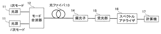
図2に、本発明のモード間パワー比測定方法の構成例を示す。光源11より出射された光波は、モード合波器12の任意のポートより入射され、対応する所望の伝搬モードとして数モード光ファイバとして機能する光ファイバ13に入射される。光ファイバ13の出射側には偏光子14が接続され、偏光子14からの出射光は受光部にて電気信号に変換される。
FIG. 2 shows a configuration example of the method for measuring the power ratio between modes of the present invention. The light wave emitted from the
得られた電気信号はスペクトルアナライザ16にて計測され、計算機17にてモード間パワー比を算出する。計算機17では、入射した伝搬モードに対応するAi(f)の成分を抽出するとともに、対象となる所望の次数(i’次)に対応する成分Ai’(f)を抽出することにより、i次の伝搬モードのi’次の伝搬モードに対するモード間パワー比XTii’は次式によって求めることができる。
ここで任意のAi(f)の抽出は、例えば予め理論的な計算により求めたGAWBSスペクトルを用いて行うことができる。すなわち関連技術において示されるように、GAWBSに寄与する音響波の固有モードは、光ファイバ13のクラッド径のみの関数で表される。そのためクラッド径が既知であれば音響波の固有モードは一意に求められる。 Here, extraction of arbitrary Ai (f) can be performed using, for example, a GAWBS spectrum obtained in advance by theoretical calculation. That is, as shown in the related art, the natural mode of the acoustic wave contributing to GAWBS is expressed as a function of only the cladding diameter of the optical fiber 13. Therefore, if the cladding diameter is known, the eigenmode of the acoustic wave can be uniquely obtained.
また、所望の伝搬モードの電界分布との重なり積分により、理論的に任意の伝搬モードに対するGAWBSスペクトルを求めることができる。実験により得られたGAWBSスペクトルから、理論的に求めたGAWBSスペクトルのうち所望の次数i以外の成分を減算することにより、所望の次数iに対するAi(f)を抽出できる。 In addition, a GAWBS spectrum for an arbitrary propagation mode can be obtained theoretically by overlapping integration with the electric field distribution of the desired propagation mode. Ai (f) for the desired order i can be extracted by subtracting components other than the desired order i from the theoretically obtained GAWBS spectrum from the GAWBS spectrum obtained by experiment.
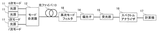
図3には、0次モード(基本モード)を利用した構成例を示している。図3では光源11側で基本モードを搬送波として入射するとともに、受光側に高次モードフィルタ18を挿入している。受光した基本モードの光波は、式(2)で示した通り、光ファイバ中の全伝搬モードに対応したGAWBSの周波数成分を有しているため、受光部15では、光ファイバ13の伝搬中にGAWBSによって偏波変調を受けた基本モードを受光し、上述と同様にモード間パワー比を計算する。
FIG. 3 shows a configuration example using the 0th-order mode (basic mode). In FIG. 3, the fundamental mode is incident on the
このとき、基本モードのみで光学系を構成するため、関連技術の単一モードの光ファイバ13向けデバイスをそのまま使用することができ、測定系を簡易に構成することができる。なお、基本モードのみを励振したときに接続点や光ファイバ13伝搬中のモード間結合によって生じる高次モードを対象としてモード間パワー比を測定する場合には、図で示したモード合波器12は不要となる。
At this time, since the optical system is configured only in the basic mode, the related-art device for the single-mode optical fiber 13 can be used as it is, and the measurement system can be configured simply. When the inter-mode power ratio is measured for a higher-order mode generated by coupling between modes at the connection point or in the optical fiber 13 when only the fundamental mode is excited, the
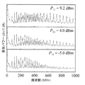
図4に、モード間パワー比測定方法に係る、数モードファイバのGAWBS周波数スペクトルの測定結果例を示す。ここで測定波長は1550nmとし、光ファイバ13は測定波長で2モード伝送が可能である数モード光ファイバとして機能する光ファイバ13とした。また入射側に合分波器を挿入し、基本モード(LP01モード)と第1高次モード(LP11モード)を任意のパワーで入射した。 FIG. 4 shows a measurement result example of the GAWBS frequency spectrum of several mode fibers according to the method for measuring the power ratio between modes. Here, the measurement wavelength was 1550 nm, and the optical fiber 13 was an optical fiber 13 functioning as a number mode optical fiber capable of two-mode transmission at the measurement wavelength. Further, a multiplexer / demultiplexer was inserted on the incident side, and the fundamental mode (LP01 mode) and the first higher-order mode (LP11 mode) were incident at an arbitrary power.
図4はLP01モードの入射パワーを6.8dBmとし、LP11モードのパワーを上段よりそれぞれ9.2dBm、4.0dBm、−5dBmとしたときのスペクトルである。測定結果は多数のピークを有する周波数スペクトルとなっており、500MHz以下の周波数帯ではLP11モードのパワーに関わらず、波形に変化がないことがわかる。当該周波数帯におけるピークはLP11モードのパワーに依存しないことから、LP01モードに対するGAWBSであると考えられる。 FIG. 4 shows spectra when the incident power in the LP01 mode is 6.8 dBm, and the power in the LP11 mode is 9.2 dBm, 4.0 dBm, and −5 dBm from the top. The measurement result is a frequency spectrum having a number of peaks, and it can be seen that there is no change in the waveform regardless of the power of the LP11 mode in the frequency band of 500 MHz or less. Since the peak in the frequency band does not depend on the power of the LP11 mode, it is considered to be a GAWBS for the LP01 mode.
一方、500MHz以上の周波数帯では、LP11モードのパワーが増加するにつれ、ピークが大きくなっていることがわかる。これらはLP11モードに対するGAWBSであると考えられる。図4からわかるように、光ファイバ13中で生じたGAWBSを観測することにより、光波の伝搬モードのパワーに対応した周波数スペクトルが得られることが確認できる。得られた周波数スペクトルにより、式(3)を用いてモード間パワー比を得ることができる。 On the other hand, in the frequency band of 500 MHz or higher, it can be seen that the peak increases as the power of the LP11 mode increases. These are considered GAWBS for the LP11 mode. As can be seen from FIG. 4, by observing the GAWBS generated in the optical fiber 13, it can be confirmed that a frequency spectrum corresponding to the power of the propagation mode of the light wave can be obtained. From the obtained frequency spectrum, the power ratio between modes can be obtained using the equation (3).
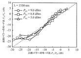
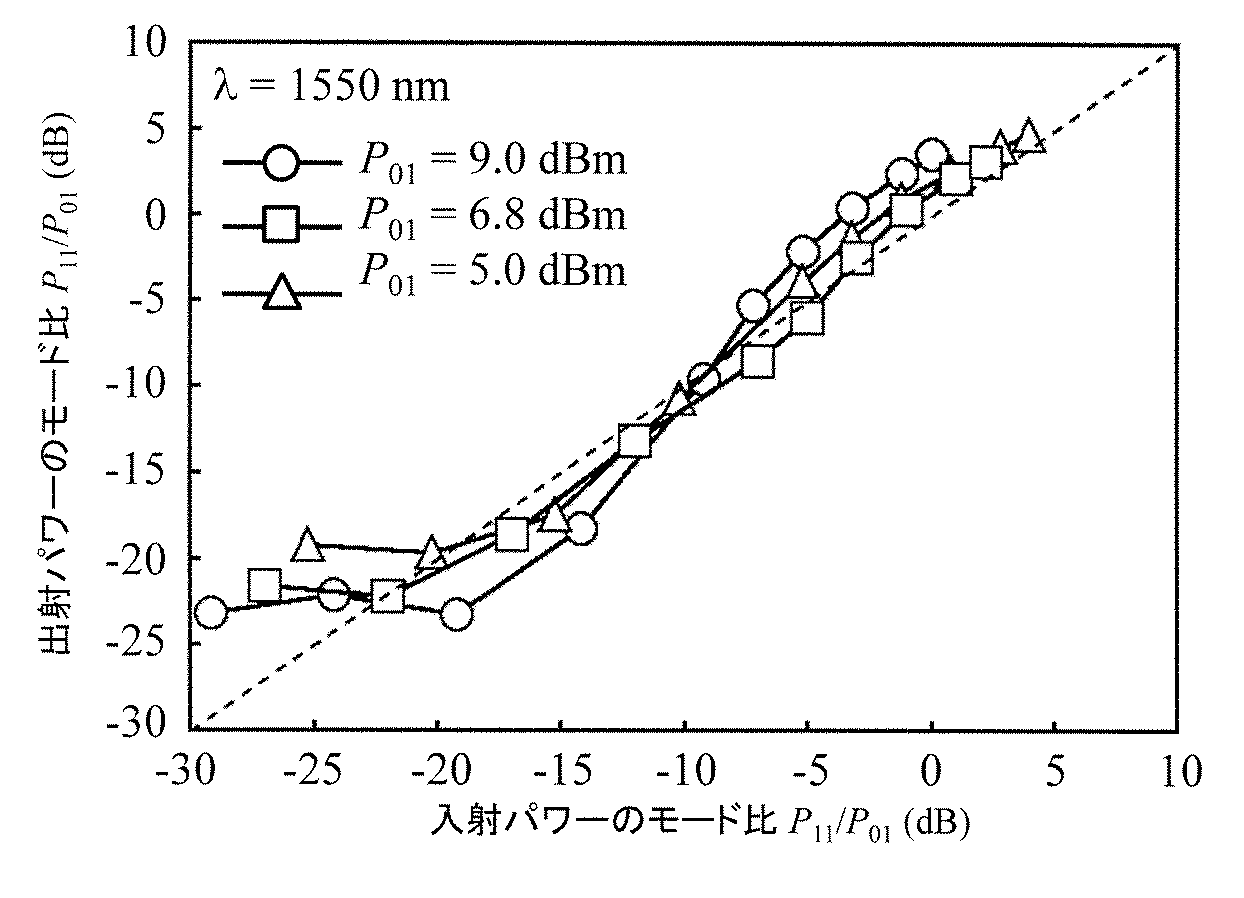
図5に、本発明のモード間パワー比測定方法を用いた、数モード光ファイバとして機能する光ファイバ13の出射端における伝搬モードパワーの測定結果例を示す。測定では図4の測定結果を得るために用いた測定系と同じものを用いた。横軸は数モード光ファイバとして機能する光ファイバ13に入射したLP01モードとLP11モードのパワー比、縦軸は本発明の測定方法による光ファイバ13の出射端でのモード間パワー比である。入射側のモード間パワー比が−20dBm以上の領域では線形に増加しており、入射したモード間パワー比と、本発明における計算機17によって測定された出射端でのモード間パワー比は比較的よく一致している。
FIG. 5 shows an example of the measurement result of the propagation mode power at the exit end of the optical fiber 13 functioning as a several-mode optical fiber using the inter-mode power ratio measurement method of the present invention. In the measurement, the same measurement system as that used to obtain the measurement result of FIG. 4 was used. The horizontal axis represents the power ratio between the LP01 mode and the LP11 mode incident on the optical fiber 13 functioning as a several-mode optical fiber, and the vertical axis represents the inter-mode power ratio at the exit end of the optical fiber 13 according to the measurement method of the present invention. The power ratio between modes on the incident side increases linearly in the region of −20 dBm or more, and the power ratio between incident modes and the power ratio between modes at the output end measured by the
一方、入射側のモード間パワー比が−20dBm以下の領域では、LP11モードの入射パワーが十分小さいにもかかわらず、出射端で得られたモード間パワー比は約−20dBであった。これは、入射側で用いたモード合波器12におけるモード間クロストークが−20dBであることから、モード合波器12の性能に起因するものと考えられる。
On the other hand, in the region where the power ratio between modes on the incident side is −20 dBm or less, the power ratio between modes obtained at the output end is about −20 dB even though the incident power of the LP11 mode is sufficiently small. This is considered to be due to the performance of the
図6に、本発明のモード間パワー比測定方法を用いた、数モード光ファイバの接続点におけるモード間パワー比の測定結果例を示す。ここで数モード光ファイバの入射端には単一モードの光ファイバ13を5m接続し、オフセットを加えて融着接続することで、LP01モードとLP11モードを任意の割合で励振した。なお図中の○はオフセットを加えた場合、□はオフセットを加えず通常の融着接続を行った場合を表す。また出射端には曲げを加えた単一モードの光ファイバ13を接続することで高次モードを除去し、基本モードのみを受光した。 FIG. 6 shows an example of the measurement result of the inter-mode power ratio at the connection point of the several-mode optical fiber using the inter-mode power ratio measuring method of the present invention. Here, the single-mode optical fiber 13 is connected to the incident end of the several-mode optical fiber by 5 m, and the LP01 mode and the LP11 mode are excited at an arbitrary ratio by fusion bonding with an offset. In the figure, ◯ represents the case where an offset is added, and □ represents the case where a normal fusion splicing is performed without adding an offset. In addition, a single-mode optical fiber 13 with a bend was connected to the emission end to remove higher-order modes, and only the fundamental mode was received.
図6の横軸はモード分波器を出射端に接続し、伝搬モードごとに分離して受光パワーを測定することで得られたモード間パワー比である。図6に示すように、本発明によって得られた測定結果と、モード分波器を用いて得られた測定結果は、パワー比が−16dB以上のとき、比較的よく一致しており、本発明のモード間パワー比測定法の妥当性が確認できる。 The horizontal axis in FIG. 6 is the inter-mode power ratio obtained by connecting the mode duplexer to the output end and measuring the received light power separately for each propagation mode. As shown in FIG. 6, the measurement result obtained by the present invention and the measurement result obtained by using the mode demultiplexer are relatively in agreement when the power ratio is -16 dB or more. The validity of the inter-mode power ratio measurement method can be confirmed.
一方、モード分波器を用いた方法では−20dB以下の値は得られなかった。これはモード分波器内におけるモード間クロストークに起因するもので、この値以下のモード間パワー比は測定できないことがわかる。 On the other hand, a value of −20 dB or less was not obtained by the method using the mode demultiplexer. This is due to crosstalk between modes in the mode duplexer, and it can be seen that a power ratio between modes below this value cannot be measured.
しかしながら本発明のモード間パワー比測定方法では−20dB以下の値も測定ができており、オフセットを用いない通常の融着接続のとき、約−25dBのモード間パワー比が生じていることがわかる。このとき、本発明のモード間パワー比測定方法では、出力側のモード分波器が不要であることから、モード分波器やモード分波器と光ファイバ13との接続点におけるクロストークの影響がないため、より精度よくモード間パワー比が得られる。 However, in the method for measuring the power ratio between modes of the present invention, a value of −20 dB or less can be measured, and it can be seen that a power ratio between modes of about −25 dB is generated in a normal fusion splice without using an offset. . At this time, since the mode demultiplexer on the output side is not necessary in the method for measuring the power ratio between modes of the present invention, the influence of the crosstalk at the mode demultiplexer or the connection point between the mode demultiplexer and the optical fiber 13 is not necessary. Therefore, the power ratio between modes can be obtained with higher accuracy.
本発明は、空間多重伝送を行う数モード光ファイバを用いた伝送システムにおける、モード間パワー比の測定に適用することができる。 The present invention can be applied to the measurement of the power ratio between modes in a transmission system using a number mode optical fiber that performs spatial multiplexing transmission.
11:光源
12:モード合波器
13:光ファイバ
14:偏光子
15:受光部
16:スペクトルアナライザ
17:計算機
18:高次モードフィルタ
11: Light source 12: Mode multiplexer 13: Optical fiber 14: Polarizer 15: Light receiving unit 16: Spectrum analyzer 17: Computer 18: High-order mode filter
Claims (3)
前記偏光手順で抽出した前記偏波変調成分を有する入射光を受光し、受光した入射光ごとに電気信号に変換する受光手順と、
前記受光手順において変換した各電気信号から前記偏波変調成分を測定するスペクトル測定手順と、
前記スペクトル測定手順で測定した電気信号に対応する偏波変調成分を互いに比較し、前記数モード光ファイバを伝搬した伝搬モード間のパワーの比率である伝搬モード間パワー比を算出する算出手順と、
を順に行うことを特徴とするモード間パワー比測定方法。 Light waves from at least one light source are incident on a few-mode optical fiber, and a polarization-modulated component due to guided acoustic Brillouin scattering is extracted for each of the plurality of incident lights from the light wave incident through the number-mode optical fiber. A polarization procedure;
A light receiving procedure for receiving incident light having the polarization modulation component extracted in the polarization procedure, and converting the received light into an electrical signal for each received light;
A spectrum measurement procedure for measuring the polarization modulation component from each electrical signal converted in the light reception procedure,
A calculation procedure for comparing the polarization modulation components corresponding to the electrical signals measured in the spectrum measurement procedure with each other and calculating a power ratio between propagation modes, which is a ratio of power between propagation modes propagated through the number mode optical fiber,
The method for measuring the power ratio between modes is characterized in that
前記偏光子が抽出した前記偏波変調成分を有する入射光を受光し電気信号に変換する受光部と、
前記受光部において変換した各電気信号から前記偏波変調成分を測定するスペクトルアナライザと、
前記スペクトルアナライザで測定した各電気信号に対応する偏波変調成分を互いに比較し、数モード光ファイバを伝搬した伝搬モード間のパワーの比率である伝搬モード間パワー比を計算する計算機と、を
備えることを特徴とするパワー比測定装置。 A polarizer for extracting a polarization modulation component by guided wave Brillouin scattering from incident light; and
A light receiving unit that receives incident light having the polarization modulation component extracted by the polarizer and converts it into an electrical signal;
A spectrum analyzer for measuring the polarization modulation component from each electrical signal converted in the light receiving unit;
A computer that compares polarization modulation components corresponding to the respective electrical signals measured by the spectrum analyzer and calculates a power ratio between propagation modes, which is a ratio of power between propagation modes propagated through several mode optical fibers, A power ratio measuring device characterized by that.
請求項2に記載のパワー比測定装置と、を
備えることを特徴とするパワー比測定システム。 At least one light source;
A power ratio measurement system comprising: the power ratio measurement device according to claim 2.
Priority Applications (1)
| Application Number | Priority Date | Filing Date | Title |
|---|---|---|---|
| JP2014114635A JP5778317B1 (en) | 2014-06-03 | 2014-06-03 | Mode-to-mode power ratio measuring method, power-ratio measuring device, and mode-to-mode power ratio measuring system |
Applications Claiming Priority (1)
| Application Number | Priority Date | Filing Date | Title |
|---|---|---|---|
| JP2014114635A JP5778317B1 (en) | 2014-06-03 | 2014-06-03 | Mode-to-mode power ratio measuring method, power-ratio measuring device, and mode-to-mode power ratio measuring system |
Publications (2)
| Publication Number | Publication Date |
|---|---|
| JP5778317B1 true JP5778317B1 (en) | 2015-09-16 |
| JP2015230165A JP2015230165A (en) | 2015-12-21 |
Family
ID=54192730
Family Applications (1)
| Application Number | Title | Priority Date | Filing Date |
|---|---|---|---|
| JP2014114635A Active JP5778317B1 (en) | 2014-06-03 | 2014-06-03 | Mode-to-mode power ratio measuring method, power-ratio measuring device, and mode-to-mode power ratio measuring system |
Country Status (1)
| Country | Link |
|---|---|
| JP (1) | JP5778317B1 (en) |
Families Citing this family (3)
| Publication number | Priority date | Publication date | Assignee | Title |
|---|---|---|---|---|
| JP6748027B2 (en) * | 2017-05-11 | 2020-08-26 | 日本電信電話株式会社 | Optical pulse test apparatus and optical pulse test method |
| US12034482B2 (en) * | 2020-06-03 | 2024-07-09 | Nec Corporation | Accurate measurement for guided acoustic-wave Brillouin scattering |
| US11467061B2 (en) * | 2020-06-08 | 2022-10-11 | Nec Corporation | Estimating mode field distribution in optical fibers from guided acoustic wave brillouin scattering |
-
2014
- 2014-06-03 JP JP2014114635A patent/JP5778317B1/en active Active
Also Published As
| Publication number | Publication date |
|---|---|
| JP2015230165A (en) | 2015-12-21 |
Similar Documents
| Publication | Publication Date | Title |
|---|---|---|
| JP6132332B2 (en) | Mode coupling measuring device for multimode optical fiber | |
| JP7322960B2 (en) | Optical fiber testing method and optical fiber testing apparatus | |
| WO2020040019A1 (en) | Optical fiber loss measurement device and optical fiber loss measurement method | |
| JP7200932B2 (en) | NONLINEARITY MEASUREMENT METHOD AND NONLINEARITY MEASUREMENT DEVICE | |
| JP7606697B2 (en) | Optical characteristic measuring device and method | |
| WO2021005800A1 (en) | Light intensity distribution measurement method and light intensity distribution measurement device | |
| JP6393563B2 (en) | Optical fiber evaluation method and evaluation apparatus | |
| JP6769944B2 (en) | Mode delay time difference distribution test method and test equipment | |
| WO2019167928A1 (en) | Propagation characteristic analysis device and propagation characteristic analysis method | |
| JP5778317B1 (en) | Mode-to-mode power ratio measuring method, power-ratio measuring device, and mode-to-mode power ratio measuring system | |
| JPWO2020075343A1 (en) | Optical fiber test method and optical fiber test equipment | |
| CN104269732B (en) | Method and device for generating microwave signal based on Brillouin amplification multi-wavelength laser device | |
| JP6475591B2 (en) | Mode dispersion coefficient measuring apparatus and mode dispersion coefficient measuring method | |
| JP6706186B2 (en) | Two-mode optical fiber characteristic analyzing method and two-mode optical fiber characteristic analyzing apparatus | |
| US11519817B2 (en) | Raman gain efficiency distribution testing method, and Raman gain efficiency distribution testing device | |
| JP7643577B2 (en) | Apparatus and method for measuring loss and crosstalk occurring in optical fiber transmission line | |
| JP5709115B1 (en) | Evaluation method and evaluation apparatus | |
| JP6748027B2 (en) | Optical pulse test apparatus and optical pulse test method | |
| JP6653616B2 (en) | Optical pulse test method and optical pulse test apparatus | |
| Liu et al. | Simultaneous measurement of MDL and DMGD in FMFs by analyzing the Rayleigh backscattering amplitudes | |
| WO2024135107A1 (en) | Optical fiber nonlinearity coefficient measurement method and device | |
| WO2023012875A1 (en) | Device, method, and system for calculating inter-core power coupling coefficient | |
| WO2022029995A1 (en) | Electric field distribution fluctuation cycle measuring method and electric field distribution fluctuation cycle measuring device | |
| Chen et al. | Study of fiber nonlinearity impact on the system capacity of two-mode fibers |
Legal Events
| Date | Code | Title | Description |
|---|---|---|---|
| TRDD | Decision of grant or rejection written | ||
| A01 | Written decision to grant a patent or to grant a registration (utility model) |
Free format text: JAPANESE INTERMEDIATE CODE: A01 Effective date: 20150707 |
|
| A61 | First payment of annual fees (during grant procedure) |
Free format text: JAPANESE INTERMEDIATE CODE: A61 Effective date: 20150708 |
|
| R150 | Certificate of patent or registration of utility model |
Ref document number: 5778317 Country of ref document: JP Free format text: JAPANESE INTERMEDIATE CODE: R150 |
|
| S533 | Written request for registration of change of name |
Free format text: JAPANESE INTERMEDIATE CODE: R313533 |
|
| R350 | Written notification of registration of transfer |
Free format text: JAPANESE INTERMEDIATE CODE: R350 |