JP5777828B2 - Resonance type power transmission device, resonance type power multiplex transmission system, resonance type power transmission device, and resonance type power reception device - Google Patents
Resonance type power transmission device, resonance type power multiplex transmission system, resonance type power transmission device, and resonance type power reception device Download PDFInfo
- Publication number
- JP5777828B2 JP5777828B2 JP2014557936A JP2014557936A JP5777828B2 JP 5777828 B2 JP5777828 B2 JP 5777828B2 JP 2014557936 A JP2014557936 A JP 2014557936A JP 2014557936 A JP2014557936 A JP 2014557936A JP 5777828 B2 JP5777828 B2 JP 5777828B2
- Authority
- JP
- Japan
- Prior art keywords
- resonance
- transmission
- reception
- power transmission
- receiving
- Prior art date
- Legal status (The legal status is an assumption and is not a legal conclusion. Google has not performed a legal analysis and makes no representation as to the accuracy of the status listed.)
- Active
Links
Images


Classifications
-
- H—ELECTRICITY
- H02—GENERATION; CONVERSION OR DISTRIBUTION OF ELECTRIC POWER
- H02J—ELECTRIC POWER NETWORKS; CIRCUIT ARRANGEMENTS OR SYSTEMS FOR SUPPLYING OR DISTRIBUTING ELECTRIC POWER; SYSTEMS FOR STORING ELECTRIC ENERGY
- H02J50/00—Circuit arrangements or systems for wireless supply or distribution of electric power
- H02J50/10—Circuit arrangements or systems for wireless supply or distribution of electric power using inductive coupling
- H02J50/12—Circuit arrangements or systems for wireless supply or distribution of electric power using inductive coupling of the resonant type
-
- H—ELECTRICITY
- H02—GENERATION; CONVERSION OR DISTRIBUTION OF ELECTRIC POWER
- H02J—ELECTRIC POWER NETWORKS; CIRCUIT ARRANGEMENTS OR SYSTEMS FOR SUPPLYING OR DISTRIBUTING ELECTRIC POWER; SYSTEMS FOR STORING ELECTRIC ENERGY
- H02J50/00—Circuit arrangements or systems for wireless supply or distribution of electric power
- H02J50/05—Circuit arrangements or systems for wireless supply or distribution of electric power using capacitive coupling
-
- H—ELECTRICITY
- H02—GENERATION; CONVERSION OR DISTRIBUTION OF ELECTRIC POWER
- H02J—ELECTRIC POWER NETWORKS; CIRCUIT ARRANGEMENTS OR SYSTEMS FOR SUPPLYING OR DISTRIBUTING ELECTRIC POWER; SYSTEMS FOR STORING ELECTRIC ENERGY
- H02J50/00—Circuit arrangements or systems for wireless supply or distribution of electric power
- H02J50/10—Circuit arrangements or systems for wireless supply or distribution of electric power using inductive coupling
-
- H—ELECTRICITY
- H02—GENERATION; CONVERSION OR DISTRIBUTION OF ELECTRIC POWER
- H02J—ELECTRIC POWER NETWORKS; CIRCUIT ARRANGEMENTS OR SYSTEMS FOR SUPPLYING OR DISTRIBUTING ELECTRIC POWER; SYSTEMS FOR STORING ELECTRIC ENERGY
- H02J50/00—Circuit arrangements or systems for wireless supply or distribution of electric power
- H02J50/50—Circuit arrangements or systems for wireless supply or distribution of electric power using additional energy repeaters between transmitting devices and receiving devices
-
- H—ELECTRICITY
- H02—GENERATION; CONVERSION OR DISTRIBUTION OF ELECTRIC POWER
- H02J—ELECTRIC POWER NETWORKS; CIRCUIT ARRANGEMENTS OR SYSTEMS FOR SUPPLYING OR DISTRIBUTING ELECTRIC POWER; SYSTEMS FOR STORING ELECTRIC ENERGY
- H02J50/00—Circuit arrangements or systems for wireless supply or distribution of electric power
- H02J50/70—Circuit arrangements or systems for wireless supply or distribution of electric power involving the reduction of electric, magnetic or electromagnetic leakage fields
Landscapes
- Engineering & Computer Science (AREA)
- Computer Networks & Wireless Communication (AREA)
- Power Engineering (AREA)
- Physics & Mathematics (AREA)
- Electromagnetism (AREA)
- Charge And Discharge Circuits For Batteries Or The Like (AREA)
Description
この発明は、共振条件が合わせられた送信用共振器及び受信用共振器を用いて電力を伝送する共振型電力伝送装置、共振型電力多重伝送システム、共振型電力送信装置及び共振型電力受信装置に関するものである。 The present invention relates to a resonance type power transmission device , a resonance type power multiplex transmission system , a resonance type power transmission device, and a resonance type power reception device that transmit power using a transmission resonator and a reception resonator in which resonance conditions are matched. It is about.
従来、電力の伝送距離を伸長するため、磁気共振型の無線電力伝送装置において、送電コイル(送信アンテナ)と受電コイル(受信アンテナ)との間に、n(nは1以上の整数値)個の中継コイル(中継アンテナ)を配設したものが知られている(例えば特許文献1参照)。 Conventionally, in order to extend the power transmission distance, n (n is an integer value of 1 or more) between a power transmission coil (transmission antenna) and a power reception coil (reception antenna) in a magnetic resonance type wireless power transmission device. A relay coil (relay antenna) is known (see, for example, Patent Document 1).
しかしながら、特許文献1に開示された中継コイルを使用する手法では、隣接するアンテナ間との磁束を共有するようにアンテナを配置する必要があり、また、伝送距離が遠い場合には中継アンテナを多数配置する必要があり、伝送装置が大型化するという課題がある。また、中継アンテナを必要とすることから、コストが増大するという課題もある。
また、隣接するアンテナ間との磁束を共有させることで電力伝送を行う構成のため、伝送経路に磁束を遮蔽するような磁性体がある場合には伝送効率が極端に低下してしまうという課題がある。
また、隣接するアンテナ間との磁束を共有させることで電力伝送を行う構成のため、アンテナ配置に制限が設けられてしまうという課題がある。However, in the technique using the relay coil disclosed in
In addition, since power transmission is performed by sharing magnetic flux between adjacent antennas, there is a problem that transmission efficiency is extremely reduced when there is a magnetic body that shields magnetic flux in the transmission path. is there.
In addition, there is a problem in that the antenna arrangement is limited due to the configuration in which power transmission is performed by sharing magnetic flux between adjacent antennas.
また、上記手法を用いた無線電力伝送装置を多重化した場合、別系統の中継アンテナを他の中継アンテナへ近づけると、アンテナ間の相互干渉が発生して伝送効率が低下してしまう。よって、多重伝送を行うためには、各系統の中継アンテナをアンテナの直径の2倍以上離して設置するか、各系統の磁束を分離するための磁気シールド対策を行う必要がある。したがって、電力伝送装置として小型化できない、又は、磁気シールド対策などのコストがかかるという課題がある。 In addition, when wireless power transmission apparatuses using the above method are multiplexed, if a relay antenna of another system is brought close to another relay antenna, mutual interference between the antennas occurs and transmission efficiency decreases. Therefore, in order to perform multiplex transmission, it is necessary to install relay antennas of each system at a distance of at least twice the diameter of the antenna, or to take magnetic shield measures to separate the magnetic flux of each system. Therefore, there is a problem that the power transmission device cannot be reduced in size or costs such as a magnetic shield countermeasure are required.
この発明は、上記のような課題を解決するためになされたもので、低コストかつ小型化が可能であり、高効率な電力伝送を可能とする共振型電力伝送装置、共振型電力多重伝送システム、共振型電力送信装置及び共振型電力受信装置を提供することを目的としている。 The present invention has been made in order to solve the above-described problems, and is a resonant power transmission apparatus and a resonant power multiplex transmission system that can be reduced in cost and reduced in size and enable high-efficiency power transmission. An object of the present invention is to provide a resonant power transmitter and a resonant power receiver .
この発明に係る共振型電力伝送装置は、送信用共振部と、送信用共振部と共振条件が合わせられた受信用共振部と、送信用共振部と受信用共振部とを1点接続する導電性物質とを備えたものである。 The resonant power transmission device according to the present invention includes a transmission resonance unit, a reception resonance unit in which the resonance conditions of the transmission resonance unit are matched, and a conductive connection that connects the transmission resonance unit and the reception resonance unit at one point. It is equipped with a sex substance .
この発明によれば、上記のように構成したので、低コストかつ小型化が可能であり、高効率な電力伝送を可能とすることができる。 According to this invention, since it comprised as mentioned above, cost reduction and size reduction are possible, and it can enable highly efficient electric power transmission.
以下、この発明をより詳細に説明するために、この発明を実施するための形態について、添付の図面に従って説明する。
実施の形態1.
図1はこの発明の実施の形態1に係る共振型電力伝送装置の構成を示すブロック図であり、図2はその回路図である。
共振型電力伝送装置は、電気信号を含む電力を伝送する装置である。この共振型電力伝送装置は、図1に示すように、送信電源1、送信アンテナ2、送信用共振器3、受信用共振器4、受信アンテナ5、受信電源6及び導電性物質7から構成されている。なお図1において、送信電源1、送信アンテナ2及び送信用共振器3は送信装置8を構成し、受信用共振器4、受信アンテナ5及び受信電源6は受信装置9を構成する。Hereinafter, in order to explain the present invention in more detail, modes for carrying out the present invention will be described with reference to the accompanying drawings.
FIG. 1 is a block diagram showing a configuration of a resonant power transmission apparatus according to
A resonance type power transmission device is a device that transmits electric power including an electric signal. As shown in FIG. 1, the resonance type power transmission apparatus includes a
送信電源1は、送信アンテナ2に対し、単一周波数の電力を供給するものである。
送信アンテナ2は、送信電源1から供給された電力を、送信用共振器3及び受信用共振器4を介して受信アンテナ5に伝送するものである。The
The
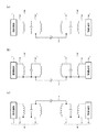
送信用共振器3及び受信用共振器4は、所定の共振条件に合わせられて共振するものである。なお、送信アンテナ2と送信用共振器3、及び受信アンテナ5と受信用共振器4は、図2(b),(c)に示すように、それぞれ接地されてもよい。
また、図1,2では、送信アンテナ2及び送信用共振器3と、受信アンテナ5及び受信用共振器4をそれぞれ別体で構成した場合について示したが、例えば図3に示すように、それぞれ一体に構成したアンテナ兼用共振器(送信用共振部、受信用共振部)10を用いてもよい。
The transmitting
1 and 2 show the case where the transmitting
受信アンテナ5は、送信用共振器3及び受信用共振器4を介して送信アンテナ2からの電力を受信するものである。
受信電源6は、受信アンテナ5により受信された電力を負荷機器など(不図示)に供給するものである。
なお、送信用共振器3及び受信用共振器4の伝送方式は特に限定されるものではなく、磁界共鳴による方式、電界共鳴による方式、電磁誘導による方式のいずれであってもよい。The
The
The transmission method of the transmitting
導電性物質7は、送信用共振器3と受信用共振器4とを1点接続するものである。ここで言う「1点接続」とは、図2に示されるように送信用共振器3と受信用共振器4とを接続する箇所が、回路図として一箇所となる接続を言う。この導電性物質7の形状は、線状や板状など、どのような形状であってもよい。なお図2(a),(b)は共振器3,4間のリターン側に線状の導電性物質7を接続したものであり、図2(c)は共振器3,4間のホット側に線状の導電性物質7を接続したものである。また、導電性物質7は、共振器3,4間を1点接続できればよく、図2に示す接続例に限るものではなく、例えば共振器3,4間で斜めに接続するようにしてもよい。
このように、共振条件が合わせられた共振器3,4間を導電性物質7で1点接続することにより、送信用共振器3の共振による振動エネルギーを導電性物質7を介して受信用共振器4に送り、当該受信用共振器4において当該振動エネルギーを共振により増幅させることができる。これにより、送信装置8から受信装置9へ電力を高効率に伝送することが可能となる。The
In this way, by connecting one point between the
次に、本発明に係る共振型電力伝送装置の適用例について、図4〜7を参照しながら説明する。
図4(a)は金属製のロープなどを本発明の導電性物質7として利用したものである。この場合、ロープの一端に送信装置8を接続し、このロープに繋がれたかご(エレベータ、ケーブルカー、ロープウェーなど)20内に受信装置9を配置する。これにより、既存のロープなどを介してかご20に電力を供給することができる。
また、図4(b)は電磁波シールドルーム21間の電力伝送に本発明を適用したものである。電磁波シールドルーム21のように電界、磁界を遮蔽する囲いがある場合、従来方式では電力を伝送することができない。しかしながら、本発明の方式では、一方の電磁波シールドルーム21aに設置された送信装置8と、他方の電磁波シールドルーム21bに設置された受信装置9とを導電性物質7で1点接続することで、容易に電力を伝送することができる。また、送信装置8と受信装置9との間に、電界、磁界を遮蔽する防護壁22などがある場合にも同様に電力伝送が可能である。Next, application examples of the resonant power transmission device according to the present invention will be described with reference to FIGS.
FIG. 4A shows a case where a metal rope or the like is used as the
FIG. 4B shows the case where the present invention is applied to power transmission between the
また、図5(a)は地上から絶縁された空間を備えた移動体(自動車、バイク、自転車など)23に本発明を適用したものである。この場合、上記空間内に送信装置8及び受信装置9を配置する。ここで、上記空間が導電性の素材で構成されている場合には、これを本発明の導電性物質7として利用することができ、送信装置8及び受信装置9を上記空間内にボルトなどで接続するだけで電力を伝送することが可能となる。よって、配線作業が不要となるとともに装置8,9の設置自由度が向上する。
また、図5(b)は既存の導電性の水道管24を本発明の導電性物質7として利用したものである。なおこの場合、水道管24は大地(GND)と絶縁されている必要がある。これにより、電力伝送のための配線作業が不要となる。
また、図6は船25から水中用装置(水中探査機など)26への電力供給に本発明を適用したものである。この場合、船25に送信装置8を配置し、水中用装置26に受信装置9を配置する。なお、導電性物質7としては既存の金属製のワイヤなどを用いればよい。FIG. 5A shows an example in which the present invention is applied to a moving body (automobile, motorcycle, bicycle, etc.) 23 having a space insulated from the ground. In this case, the
FIG. 5B shows an example in which an existing
FIG. 6 shows the application of the present invention to power supply from a
また、図7(a)の左側は既存の電線27を本発明の導電性物質7として利用したものであり、右側は屋内の既存の配線28を本発明の導電性物質7として利用したものである。なお、符号29,30はそれぞれブレーカ、コンセントである。これにより、本来、電線27や配線28を流れている商用周波数の電力に対して、別の高周波の電力を伝送することが可能となる。なお、図7(b)に示すように、送信電源1の電力として、屋外に設置されたソーラー発電機31による電力を用いてもよい。
Further, the left side of FIG. 7 (a) shows that the existing
以上のように、この実施の形態1によれば、共振条件が合わせられた送信用共振器3及び受信用共振器4を用いて電力を伝送する共振型電力伝送装置であって、電力を供給する送信電源1と、送信電源1からの電力を伝送する送信アンテナ2と、送信用共振器3と受信用共振器4とを1点接続する導電性物質7と、送信用共振器3及び受信用共振器4を介して送信アンテナ2からの電力を受信する受信アンテナ5と、受信アンテナ5により受信された電力を受信する受信電源6とを備えたので、簡易な構成のため低コストかつ小型化が可能であり、近距離から遠距離まで高効率な電力伝送を可能とすることができる。
また、従来方式による送信アンテナ2、送信用共振器3、受信用共振器4及び受信アンテナ5間の直接的な空間磁束の共振結合を必要とせず、伝送距離や方向を任意に設定することができる。As described above, according to the first embodiment, the resonance type power transmission apparatus transmits power using the
Further, it is possible to arbitrarily set the transmission distance and direction without requiring direct resonant coupling of spatial magnetic flux between the
実施の形態2.
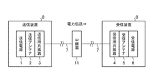
図8はこの発明の実施の形態2に係る共振型電力伝送装置の構成を示すブロック図である。この図8に示す実施の形態2に係る共振型電力伝送装置は、図1に示す実施の形態1に係る共振型電力伝送装置に中継器11を追加したものである。その他の構成は同様であり、同一の符号を付してその説明を省略する。
FIG. 8 is a block diagram showing a configuration of a resonant power transmission apparatus according to
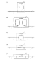
中継器11は、送信用共振器3と受信用共振器4との間に配置され、送信用共振器3及び受信用共振器4の共振条件と同じ共振条件に合わせられた中継用の共振器である。この中継器11としては、例えば図9に示すようなものが挙げられる。図9(a)は共振器を1点接続したもの,図9(b)は送信側と受信側の共振器を無線接続したもの、図9(c)〜(e)は接続された導電性物質7のインピーダンスを利用したものである。
この中継器11を用いることで、送信用共振器3からの電力を一端中継器11で受信して増幅させて受信用共振器4に送ることができ、伝送効率を向上させることができる。The
By using the
以上のように、この実施の形態2によれば、送信用共振器3と受信用共振器4との間に、共振条件が合わせられた中継器11を備えたので、実施の形態1に示す構成に対し、より伝送効率を向上させることが可能となる。
As described above, according to the second embodiment, the
実施の形態3.
図10はこの発明の実施の形態3に係る共振型電力伝送装置の構成・適用例を示す図である。この図10に示す実施の形態3に係る共振型電力伝送装置は、図1に示す実施の形態1に係る共振型電力伝送装置の構成に対し、受信用共振器4を複数設け、導電性物質7により送信用共振器3と複数の受信用共振器4とをそれぞれ接続させたものである。また図10では、受信装置9に代えて、受信アンテナ5及び受信電源6からなる受信装置9bを備え、受信用共振器4とは別体に構成している。その他の構成は同様であり、同一の符号を付してその説明を省略する。
FIG. 10 is a diagram showing a configuration / application example of a resonant power transmission apparatus according to
図10は駐車エリアに駐車された車両32への電力供給に本発明を適用したものである。この場合、複数の受信用共振器4を各駐車エリアの地面の下に配置する。これにより、受信装置9bを備えた車両32が上記駐車エリアに駐車した際に、当該車両32に電力を供給することができる。
FIG. 10 shows the application of the present invention to the power supply to the
また、図11(a)は電車33への電力供給に本発明を適用したものである。この場合、レール34及び電車33の車輪35を導電性物質7として利用し、レール34に接続された送信装置8から各車両に配置された受信装置9に電力を供給する。なお、レール34はGND接地させず、電位的に浮かせた状態である必要がある。従来、高速鉄道では、電力伝送用のパンタグラフの使用が困難となっていたが、本発明を適用することでパンタグラフを用いずに電力伝送を行うことが可能となる。
また、図11(b)は電車33への別の電力供給に本発明を適用したものである。図11(b)は、車内の座席36の下又は後部座席で利用するテーブル37内に受信用共振器4を配置したものである。これにより、利用者が受信装置9bを備えた機器(スマートフォン、PC、モバイルルータなど)を持って座るだけで、又はテーブル37上に置くだけで、当該機器に電力を供給することができる。よって、機器の充電の際にコンセントに接続する必要がなくなり、利便性が向上する。なお、送信装置8は電車33の外に設置する場合に限らず、車内に設置するようにしてもよい。FIG. 11A shows the case where the present invention is applied to power supply to the
FIG. 11B shows the application of the present invention to another power supply to the
また、図12(a)はコードレスアイロン38への電力供給に本発明を適用したものである。この場合、複数の受信用共振器4をアイロン台39の内部に平面状に配置する。これにより、受信装置9bを備えたコードレスアイロン38を用いてアイロン掛けを行っている間、当該コードレスアイロン38に電力を供給することができ、温度が下がることなく連続駆動させることができる。
また、図12(b)はシート部材(テーブルクロス、マット、カーペットなど)40に本発明を適用したものである。この場合、複数の受信用共振器4をシート部材40の内部に平面状に配置する。これにより、受信装置9bを備えた機器(掃除機など)がシート部材40上に置かれた際に、当該機器に電力を供給することができる。なお、図13(a)に示すように、既存の配線28(又は電線27)を本発明の導電性物質7として利用したものに上記シート部材40を用いてもよい。図13(b),14(a)はさらに、送信電源1の電力として、屋外に設置されたソーラー発電機31による電力を用いたものである。また、図14(b)は導電性物質7をコンセント30の一極を介して接続したものである。なお図14(b)では中継器11を用いているが、用いなくてもよい。FIG. 12A shows the application of the present invention to the power supply to the
FIG. 12B shows the sheet member (table cloth, mat, carpet, etc.) 40 applied to the present invention. In this case, the plurality of receiving
また、図15(a)は歩行ロボット41への電力供給に本発明を適用したものである。この場合、複数の受信用共振器4を歩行面(地面、床など)の下に平面状に配置し、歩行ロボット41の足部分に受信装置9bを配置する。これにより、歩行ロボット41が歩行面を歩行している間、当該歩行ロボット41に電力を供給することができる。また、送信装置8に情報送信装置42を設け、受信装置9bに情報受信装置43を設けることで、電力伝送に限らず、歩行に関する情報(歩行位置、向きなど)を伝送することも可能である。また、歩行ロボット41に限らず、靴、杖、掃除機などにも同様に適用可能である。なお、靴に本発明を適用した場合、例えば視覚障害者向けのアプリケーションを提供することができる。すなわち、受信装置9bにバイブレータを接続し、従来の点字マットが配置された箇所に受信用共振器4を配置することで、当該靴が受信用共振器4上に位置した際にバイブレータの振動により点字マットを模擬することができる。
FIG. 15A shows the application of the present invention to power supply to the walking
また、図15(b)は、ゴルフクラブ44のスイングの加速度や圧力、角度などを計測するセンサ45への電力供給に本発明を適用したものである。この場合、複数の受信用共振器4を地面の下に平面状に配置し、ゴルフクラブ44のヘッド部分にセンサ45を有する受信装置9bを配置する。これにより、ゴルフクラブ44を地面に近づけた際に、当該ゴルフクラブ44のセンサ45に電力を供給することができる。これにより、センサ45を動作させるためのバッテリをゴルフクラブ44内に設ける必要がなくなり、ゴルフクラブ44自体を軽量化させることができる。また、ゴルフクラブ44に限らず、テニス・卓球ラケット、バット、釣竿、モバイル機器などにも同様に適用可能である。
FIG. 15B shows the application of the present invention to power supply to a
また、図16は飛翔体(飛行機、ヘリコプター、気球、ミサイル、人工衛星、宇宙ステーション、リニアモーターカーなど)46に本発明を適用したものである。ここで、飛翔体46内の空間が導電性の素材で構成されている場合には、これを本発明の導電性物質7として利用することができ、送信装置8及び受信装置9を上記空間内にボルトなどで接続するだけで電力を伝送することが可能となる。よって、配線作業が不要となるとともに装置8,9の設置自由度が向上する。
FIG. 16 shows the case where the present invention is applied to a flying object (airplane, helicopter, balloon, missile, artificial satellite, space station, linear motor car, etc.) 46. Here, when the space in the flying
また、図17(a)はベッド47に本発明を適用したものである。この場合、複数の受信用共振器4をベッド47の内部に平面状に配置する。これにより、受信装置9bを備えた機器をベッド47に置くだけで、当該機器に電力を供給することができる。なお、受信用共振器4として、ベッド47のスプリング機能を兼用した共振器を用いてもよい。
また、図17(b)は風呂48に本発明を適用したものである。この場合、複数の受信用共振器4を風呂48の壁面の裏側に平面状に配置する。これにより、受信装置9bを備えた機器(テレビ、ラジオ、スマートフォン、電気シェーバー、めがね洗浄器、ジェットバブル装置など)を当該壁面に近づけるだけで、当該機器に電力を供給することができる。なお、本発明では送信側と受信側が1点で接続されているため、電流が流れるルートがなく、感電の恐れがないという利点もある。FIG. 17A shows the
FIG. 17B shows the case where the present invention is applied to the
以上のように、この実施の形態3によれば、受信用共振器4は複数設けられ、導電性物質7は、送信用共振器3と複数の受信用共振器4とを接続するように構成したので、実施の形態1における効果に加え、単体の送信装置8で、広範囲に対して電力供給を行うことが可能となる。すなわち、従来の方法では、送信装置と受信装置とを1対1の関係で設ける必要があり、広範囲に対する電力供給では設置コストが増大してしまう。それに対し、本発明では単体の送信装置8を一線接続により複数の受信装置9と接続させることで容易に電力伝送ができるため、安価に広範囲に対する電力伝送が可能となる。
As described above, according to the third embodiment, a plurality of receiving
実施の形態4.
図18はこの発明の実施の形態4に係る共振型電力伝送装置の構成・適用例を示す図である。この図18に示す実施の形態4に係る共振型電力伝送装置は、図1に示す実施の形態1に係る共振型電力伝送装置の導電性物質7を2つに分離させ、一方を送信用共振器3に接続させ、他方を受信用共振器4に接続させたものである。そして、両者が接触した際に送信装置8から受信装置9への電力伝送を可能とする。その他の構成は同様であり、同一の符号を付してその説明を省略する。なお、送信電源1、送信アンテナ2、送信用共振器3及び分割した一方の導電性物質7は共振型電力送信装置を構成し、受信用共振器4、受信アンテナ5、受信電源6及び分割した他方の導電性物質7は共振型電力受信装置を構成する。
FIG. 18 is a diagram showing a configuration / application example of a resonant power transmission apparatus according to
図18は駐車エリアに駐車された車両32への電力供給に本発明を適用したものである。この場合、送信装置8に接続された導電性物質7の末端には、受信装置9に接続された導電性物質7(接触線71)との接触を容易とするため、電極板72などの導電性の板状部材が設けられている。そして、この電極板72が各駐車エリアの地面に配置されている。これにより、接触線71を有する受信装置9を備えた車両32が上記駐車エリアに駐車した際に、電極板72と接触線71が接触することで、当該車両32に電力を供給することができる。
FIG. 18 is an application of the present invention to power supply to a
また、図19(a)は電車33への電力供給に本発明を適用したものである。この場合、車内の後部座席36で利用するテーブル37上に送信装置8に接続された電極板72が配置されている。これにより、接触線71を有する受信装置9を備えた機器をテーブル37の電極板72上に置くだけで、当該機器に電力を供給することができる。なお、送信装置8は電車33の外に設置する場合に限らず、車両内に設置するようにしてもよい。
また、図19(b)は風呂48に本発明を適用したものである。この場合、風呂48の壁面に送信装置8に接続された電極板72が配置されている。これにより、接触構造(磁石による吸引構造など)を有する受信装置9を備えた機器を壁面の電極板72に接触させるだけで、当該機器に電力を供給することができる。なお、本発明では送信側と受信側が1点で接続されているため、電流が流れるルートがなく、感電の恐れがないという利点もある。FIG. 19A shows the application of the present invention to power supply to the
FIG. 19B shows the case where the present invention is applied to the
また、図20(a)はテーブル49に本発明を適用したものである。この場合、テーブル49上に送信装置8に接続された導電性シート部材50などを貼り付ける。これにより、接触線71を有する受信装置9を備えた機器を導電性シート部材50上に置くだけで、当該機器に電力を供給することができる。
また、図20(b)はシート部材に本発明を適用したものである。この場合、シート部材として送信装置8に接続された導電性のシート部材50を用いる。これにより、接触線71を有する受信装置9を備えた機器が導電性シート部材50上に置かれた際に、当該機器に電力を供給することができる。なお、図21(a)に示すように、既存の配線28(又は電線27)を本発明の導電性物質7として利用したものに上記導電性シート部材50を用いてもよい。図21(b),図22(a)はさらに、送信電源1の電力として、屋外に設置されたソーラー発電機31による電力を用いたものである。また、図22(b)は導電性物質7をコンセント30の一極を介して接続したものである。なお図22(b)では中継器11を用いているが、用いなくてもよい。FIG. 20A shows the table 49 applied with the present invention. In this case, a
FIG. 20B shows the sheet member applied with the present invention. In this case, a
また、図23(a)は歩行ロボット41への電力供給に本発明を適用したものである。この場合、歩行面上に送信装置8に接続された導電性シート部材50などを配置し、歩行ロボット41の靴の底面に受信装置9に接続された電極板72を配置する。これにより、歩行ロボット41が歩行面を歩行している間、当該歩行ロボット41に電力を供給することができる。また、送信装置8に情報送信装置42を設け、受信装置9に情報受信装置43を設けることで、電力伝送に限らず、歩行に関する情報(歩行位置、向きなど)を伝送することも可能である。また、歩行ロボット41に限らず、靴、杖、掃除機などにも同様に適用可能である。なお、靴に本発明を適用した場合、例えば視覚障害者向けのアプリケーションを提供することができる。すなわち、靴にバイブレータを設け、従来用いた点字マットに代えて送信装置8が接続された導電性シート部材50を配置することで、当該靴が導電性シート部材50に接触した際にバイブレータの振動により点字マットを模擬することができる。
FIG. 23A shows an example in which the present invention is applied to power supply to the walking
また、図23(b)はゴルフクラブ44のスイングの加速度や圧力、角度などを計測するセンサ45への電力供給に本発明を適用したものである。この場合、利用者がモバイル型の送信装置8をポケットなどに入れて持ち、導電性シャフト73で構成されたゴルフクラブ44のヘッド部分に受信装置9を配置し、グリップ部分に導電性シャフト73を介して受信装置9に接続された電極板72を配置する。これにより、利用者がゴルフクラブ44を握った際に、当該ゴルフクラブ44のセンサ45に電力を供給することができる。これによりセンサ45を動作させるためのバッテリをゴルフクラブ44内に設ける必要がなくなるため、ゴルフクラブ44自体を軽量化させることができる。また、ゴルフクラブ44に限らず、テニス・卓球ラケット、バット、釣竿、モバイル機器などにも同様に適用可能である。
FIG. 23B shows the application of the present invention to the power supply to the
また、図24(a)はかばん51内の機器への電力供給に本発明を適用したものである。この場合、床に送信装置8に接続された導電性シート部材50を配置し、かばん51内に受信装置9に接続された電極板72を配置する。これにより、かばん51を導電性シート部材50上に置くだけで、当該かばん51内の受信装置9に電力を供給することができる。また、図24(b)はかばん51の生地内に複数の受信用共振器4を平面上に配置したものである。
FIG. 24A shows the case where the present invention is applied to power supply to the devices in the
以上のように、この実施の形態4によれば、導電性物質7を2つに分離し、一方を送信用共振器3に接続し、他方を受信用共振器4に接続しても、実施の形態3と同様の効果を得ることができる。
As described above, according to the fourth embodiment, even if the
実施の形態5.
図25はこの発明の実施の形態5に係る共振型電力多重伝送システムの構成を示す図である。この図25に示す実施の形態5に係る共振型電力多重伝送システムは、図1に示す実施の形態1に係る共振型電力伝送装置を複数系統設けたものである。その他の構成は同様であり、同一の符号を付してその説明を省略する。
FIG. 25 is a diagram showing a configuration of a resonant power multiplex transmission system according to
図25に示すように、本発明による共振型電力伝送装置を多重に構成することで、各系統の相互干渉がなく、独立した電力伝送を可能としたシステムを得ることができる。そして、伝送経路上での相互干渉がないため、各系統を近づけたシステム構成が可能である。したがって、例えば駐車エリアに駐車して充電を行った車両32に対し課金を行うための課金・情報システムに本発明を適用することができる。
また、伝送経路上での相互干渉がないため、使用する周波数を一つに固定できることから、ISM帯などを使用することにより、電波法の規制を満足した設計を容易に行える。以上により、送信電力の大電力化や電磁シールド構造の簡易化などが可能である。As shown in FIG. 25, by configuring the resonant power transmission apparatus according to the present invention in a multiplex manner, it is possible to obtain a system that allows independent power transmission without mutual interference between systems. Further, since there is no mutual interference on the transmission path, a system configuration in which each system is brought close is possible. Therefore, for example, the present invention can be applied to a billing / information system for billing a
In addition, since there is no mutual interference on the transmission path, the frequency to be used can be fixed to one. Therefore, the design satisfying the regulations of the Radio Law can be easily performed by using the ISM band or the like. As described above, it is possible to increase the transmission power and simplify the electromagnetic shield structure.
なお、図25(a)は各駐車エリアの地面の下に受信用共振器4を配置した場合を示しており、図25(b)は各駐車エリアの地面上に電極板72を配置した場合を示している。
25A shows a case where the receiving
以上のように、この実施の形態5によれば、本発明の共振型電力伝送装置を多重に構成したので、各系統の相互干渉がなく、独立した電力伝送を可能とすることができる。よって、小型化が可能となる。また、多重伝送においても伝送経路上での相互干渉がないため、使用する周波数を一つに固定できることから、ISM帯などを使用することにより、電波法の規制を満足した設計を容易に行える。よって、送信電力の大電力化や電磁シールド構造の簡易化などが可能である。 As described above, according to the fifth embodiment, since the resonant power transmission device of the present invention is configured in a multiple manner, there is no mutual interference between the systems, and independent power transmission can be achieved. Therefore, the size can be reduced. In addition, since there is no mutual interference on the transmission path even in the multiplex transmission, the frequency to be used can be fixed to one, so that the design satisfying the regulations of the Radio Law can be easily performed by using the ISM band or the like. Therefore, it is possible to increase the transmission power and simplify the electromagnetic shield structure.
実施の形態6.
図26はこの発明の実施の形態6に係る共振型電力多重伝送システムの構成を示す回路図である。この図26に示す実施の形態6に係る共振型電力多重伝送システムは、図25に示す実施の形態5に係る共振型電力多重伝送システムの導電性物質7を共通化したものである。このように構成しても多重伝送が可能である。この場合、1つの系統が故障により動作しなくなった場合にも他の系統はその影響を受けることなく動作させることができる(故障分離が可能)。よって、人工衛星や風力発電などで用いられるスリップリング装置の代替機能として用いることができる。
FIG. 26 is a circuit diagram showing a configuration of a resonant power multiplex transmission system according to
以上のように、この実施の形態6によれば、共振型電力多重伝送システムにおいて、各共振型電力伝送装置の導電性物質7を共通化しても、実施の形態5と同様の効果を得ることができる。
As described above, according to the sixth embodiment, in the resonant power multiplex transmission system, even if the
また、実施の形態1−6では、送信アンテナ2及び受信アンテナ5を各々単一のコイルから構成する場合について示した。しかしながら、これに限るものではなく、各コイルを、各々例えば給電用コイル及び共鳴用コイルから構成してもよく、2個以上のコイルで構成するようにしてもよい。
In Embodiment 1-6, the
また、実施の形態1−6において、受信用共振器4では、対となる送信用共振器3間の距離や負荷電流・負荷インピーダンスなどによって共振条件が変化する。そこで、受信側に、このような伝送状況の変化に応じて、受信用共振器4に対して成立させる共振条件を可変とする受信電源回路を追加してもよい。
同様に、実施の形態1−6において、送信用共振器3では、対となる受信用共振器4間の距離や負荷電流・負荷インピーダンスなどによって共振条件が変化する。そこで、送信側に、このような伝送状況の変化に応じて、送信用共振器3に対して成立させる共振条件を可変とする送信電源回路を追加してもよい。
In the first to sixth embodiments, the resonance condition of the receiving
Similarly, in the first to sixth embodiments, in the
なお、本願発明はその発明の範囲内において、各実施の形態の自由な組み合わせ、あるいは各実施の形態の任意の構成要素の変形、もしくは各実施の形態において任意の構成要素の省略が可能である。 In the present invention, within the scope of the invention, any combination of the embodiments, or any modification of any component in each embodiment, or omission of any component in each embodiment is possible. .
この発明に係る共振型電力伝送装置及び共振型電力多重伝送システムは、送信用共振器と受信用共振器とを1点接続する導電性物質を備え、低コストかつ小型化が可能であり、高効率な電力伝送が実現できるため、電磁波シールドルーム間の電力伝送等に用いるのに適している。 The resonant power transmission device and the resonant power multiplex transmission system according to the present invention include a conductive material that connects the transmitting resonator and the receiving resonator at one point, and can be reduced in cost and size. Since efficient power transmission can be realized, it is suitable for power transmission between electromagnetic shielding rooms.
1 送信電源、2 送信アンテナ、3 送信用共振器、4 受信用共振器、5 受信アンテナ、6 受信電源、7 導電性物質、8 送信装置、9,9b 受信装置、10 アンテナ兼用共振器、11 中継器、20 かご、21,21a,21b 電磁波シールドルーム、22 防護壁、23 移動体、24 水道管、25 船、26 水中用装置、27 電線、28 配線、29 ブレーカ、30 コンセント、31 ソーラー発電機、32 車両、33 電車、34 レール、35 車輪、36 座席、37 テーブル、38 コードレスアイロン、39 アイロン台、40 シート部材、41 歩行ロボット、42 情報送信装置、43 情報受信装置、44 ゴルフクラブ、45 センサ、46 飛翔体、47 ベッド、48 風呂、49 テーブル、50 導電性シート部材、51 かばん、71 接触線、72 電極板、73 導電性シャフト。
DESCRIPTION OF
Claims (15)
前記送信用共振部と共振条件が合わせられた受信用共振部と、 A resonance unit for reception in which resonance conditions are matched with the resonance unit for transmission;
前記送信用共振部と前記受信用共振部とを1点接続する導電性物質と A conductive substance that connects the transmitting resonance part and the receiving resonance part at one point;
を備えた共振型電力伝送装置。 A resonance type power transmission device.
前記受信用共振部は、別体に構成された受信用共振器と受信アンテナとから成る
ことを特徴とする請求項1記載の共振型電力伝送装置。 The transmission resonance unit includes a transmission antenna and a transmission resonator configured separately,
The resonant power transmission apparatus according to claim 1, wherein the reception resonance unit includes a reception resonator and a reception antenna which are separately configured .
ことを特徴とする請求項1記載の共振型電力伝送装置。 The resonance type power transmission device according to claim 1, further comprising a relay resonator provided between the transmission resonance unit and the reception resonance unit , wherein the resonance conditions are matched.
前記導電性物質は、前記送信用共振部と前記複数の受信用共振部とをそれぞれ接続する
ことを特徴とする請求項1記載の共振型電力伝送装置。 A plurality of the receiving resonance parts are provided,
The conductive material is, resonant power transmission apparatus according to claim 1, wherein the connecting the transmission resonance unit and said plurality of reception resonator unit respectively.
ことを特徴とする請求項1記載の共振型電力伝送装置。 2. The resonant power transmission device according to claim 1, wherein the conductive substance is separated into two parts, one is connected to the transmission resonance unit , and the other is connected to the reception resonance unit .
ことを特徴とする請求項1記載の共振型電力伝送装置。 The resonant power transmission apparatus according to claim 1, wherein the transmission resonance unit and the reception resonance unit perform magnetic field resonance.
ことを特徴とする請求項1記載の共振型電力伝送装置。 The resonant power transmission apparatus according to claim 1, wherein the transmission resonance unit and the reception resonance unit perform electric field resonance.
ことを特徴とする請求項1記載の共振型電力伝送装置。 The resonant power transmission apparatus according to claim 1, wherein the transmission resonance unit and the reception resonance unit perform electromagnetic induction.
ことを特徴とする請求項2記載の共振型電力伝送装置。 It said transmitting antenna and said receiving antenna, resonant power transmission apparatus according to claim 2, characterized in that it is constituted from each of two or more coils.
ことを特徴とする請求項1記載の共振型電力伝送装置。 Resonant power transmission apparatus according to claim 1, characterized in that a receiving power supply circuit for varying the resonance condition of the receiving resonance unit corresponding to transmission conditions of the reception resonator unit.
ことを特徴とする請求項1記載の共振型電力伝送装置。 The resonance type power transmission device according to claim 1, further comprising a transmission power supply circuit that varies a resonance condition of the transmission resonance unit according to a transmission state of the transmission resonance unit .
前記共振型電力伝送装置は、
前記送信用共振部と前記受信用共振部とを1点接続する導電性物質を備えた
ことを特徴とする共振型電力多重伝送システム。 A resonance type power multiplex transmission system including a plurality of resonance type power transmission devices including a transmission resonance unit and a reception resonance unit in which resonance conditions are matched with the transmission resonance unit ,
The resonant power transmission device is:
A resonance type power multiplex transmission system comprising a conductive substance that connects the transmission resonance unit and the reception resonance unit at one point .
ことを特徴とする請求項12記載の共振型電力多重伝送システム。 13. The resonant power multiplex transmission system according to claim 12, wherein conductive materials of the respective resonant power transmission apparatuses are shared.
前記送信用共振部に導電性物質と1点で接続される接続部と A connecting portion connected to the transmitting resonance portion at one point with a conductive substance;
を備えた共振型電力送信装置。 A resonance type power transmission device.
前記受信用共振部に導電性物質と1点で接続される接続部と A connection portion connected to the receiving resonance portion at one point with a conductive substance;
を備えた共振型電力受信装置。 A resonance type power receiving apparatus.
Priority Applications (1)
| Application Number | Priority Date | Filing Date | Title |
|---|---|---|---|
| JP2014557936A JP5777828B2 (en) | 2013-08-23 | 2014-08-20 | Resonance type power transmission device, resonance type power multiplex transmission system, resonance type power transmission device, and resonance type power reception device |
Applications Claiming Priority (6)
| Application Number | Priority Date | Filing Date | Title |
|---|---|---|---|
| JP2013173311 | 2013-08-23 | ||
| JP2013173311 | 2013-08-23 | ||
| JPPCT/JP2013/080913 | 2013-11-15 | ||
| PCT/JP2013/080913 WO2015025438A1 (en) | 2013-08-23 | 2013-11-15 | Resonant power transmission device and resonant power multiplexed transmission system |
| JP2014557936A JP5777828B2 (en) | 2013-08-23 | 2014-08-20 | Resonance type power transmission device, resonance type power multiplex transmission system, resonance type power transmission device, and resonance type power reception device |
| PCT/JP2014/071756 WO2015025881A1 (en) | 2013-08-23 | 2014-08-20 | Resonant electrical power transmission device and resonant electrical power multiplexed transmission system |
Publications (2)
| Publication Number | Publication Date |
|---|---|
| JP5777828B2 true JP5777828B2 (en) | 2015-09-09 |
| JPWO2015025881A1 JPWO2015025881A1 (en) | 2017-03-02 |
Family
ID=52483240
Family Applications (1)
| Application Number | Title | Priority Date | Filing Date |
|---|---|---|---|
| JP2014557936A Active JP5777828B2 (en) | 2013-08-23 | 2014-08-20 | Resonance type power transmission device, resonance type power multiplex transmission system, resonance type power transmission device, and resonance type power reception device |
Country Status (7)
| Country | Link |
|---|---|
| US (1) | US9712000B2 (en) |
| EP (1) | EP3046218B1 (en) |
| JP (1) | JP5777828B2 (en) |
| KR (1) | KR101616685B1 (en) |
| CN (1) | CN105474510B (en) |
| TW (1) | TWI549398B (en) |
| WO (2) | WO2015025438A1 (en) |
Families Citing this family (10)
| Publication number | Priority date | Publication date | Assignee | Title |
|---|---|---|---|---|
| US10075024B2 (en) * | 2015-05-22 | 2018-09-11 | La-Z-Boy Incorporated | Apparatus and method for wireless power transfer in furniture |
| US10944282B2 (en) | 2015-05-28 | 2021-03-09 | Nike, Inc. | Transportation apparatus with NFC charger |
| WO2017126112A1 (en) * | 2016-01-22 | 2017-07-27 | 三菱電機エンジニアリング株式会社 | Power transmission device, high-frequency power supply, and high-frequency rectification circuit |
| US10377252B2 (en) * | 2016-12-29 | 2019-08-13 | Intel Corporation | Robots and apparatus, systems and methods for powering robots |
| EP3454452A1 (en) * | 2017-09-08 | 2019-03-13 | TE Connectivity Nederland B.V. | Inductive coupled power transfer (icpt) in multiple gap applications |
| JP7069836B2 (en) * | 2018-03-02 | 2022-05-18 | トヨタ自動車株式会社 | Coil unit |
| CN108880005A (en) * | 2018-08-07 | 2018-11-23 | 佛山市甜慕链客科技有限公司 | A kind of wireless charging method of wireless signal conveyer system |
| US11251642B2 (en) * | 2019-03-20 | 2022-02-15 | Geoffrey Herbert Harris | Wireless charging apparatus |
| KR102379486B1 (en) * | 2019-11-15 | 2022-03-25 | 대구대학교 산학협력단 | System for simultaneous wireless power and data transfer between satellite and payload using repeater |
| US20220106155A1 (en) * | 2020-10-02 | 2022-04-07 | Otis Elevator Company | Elevator system including wireless power transfer |
Family Cites Families (19)
| Publication number | Priority date | Publication date | Assignee | Title |
|---|---|---|---|---|
| WO1998050993A1 (en) | 1997-05-06 | 1998-11-12 | Auckland Uniservices Limited | Inductive power transfer across an extended gap |
| FR2832272B1 (en) * | 2001-11-09 | 2004-09-24 | Commissariat Energie Atomique | PASSIVE DEVICE FOR INCREASING TRANSMISSION EFFICIENCY OF RADIO FREQUENCY SYSTEMS |
| JP2006270055A (en) * | 2005-02-28 | 2006-10-05 | Matsushita Electric Ind Co Ltd | Resonant transformer and power supply unit using the same |
| JP4453741B2 (en) * | 2007-10-25 | 2010-04-21 | トヨタ自動車株式会社 | Electric vehicle and vehicle power supply device |
| TWI361540B (en) * | 2007-12-14 | 2012-04-01 | Darfon Electronics Corp | Energy transferring system and method thereof |
| US8598743B2 (en) * | 2008-09-27 | 2013-12-03 | Witricity Corporation | Resonator arrays for wireless energy transfer |
| US9318922B2 (en) * | 2008-09-27 | 2016-04-19 | Witricity Corporation | Mechanically removable wireless power vehicle seat assembly |
| NL2002116C (en) * | 2008-10-20 | 2010-04-21 | Stichting Noble House | METHOD FOR DETERMINING THE PRESENCE OF A TRANSMITTER AND A RECEIVER AND A SYSTEM FURNISHED THEREFORE. |
| US8274178B2 (en) * | 2009-06-21 | 2012-09-25 | Christopher Allen Tucker | System of transmission of wireless energy |
| JP2011160634A (en) | 2010-02-04 | 2011-08-18 | Casio Computer Co Ltd | Power transmission system and power transmission device |
| JP5691458B2 (en) * | 2010-03-31 | 2015-04-01 | 日産自動車株式会社 | Non-contact power feeding apparatus and non-contact power feeding method |
| JP5740200B2 (en) | 2011-04-22 | 2015-06-24 | 矢崎総業株式会社 | Resonant non-contact power feeding system, power receiving side device, and power transmitting side device |
| US9728997B2 (en) * | 2011-09-21 | 2017-08-08 | Samsung Electronics Co., Ltd. | Wireless power transmission system |
| US9431856B2 (en) * | 2012-01-09 | 2016-08-30 | Pabellon, Inc. | Power transmission |
| KR102121919B1 (en) * | 2012-02-29 | 2020-06-11 | 한국전자통신연구원 | Apparatus for transferring power |
| KR101262615B1 (en) * | 2012-03-05 | 2013-05-08 | 엘지이노텍 주식회사 | Apparatus for transmitting wireless power, apparatus for receiving wireless power, system for transmitting wireless power and method for transmitting wireless power |
| WO2013176752A2 (en) * | 2012-05-20 | 2013-11-28 | Access Business Group International Llc | Wireless power supply system |
| US9805863B2 (en) * | 2012-07-27 | 2017-10-31 | Thoratec Corporation | Magnetic power transmission utilizing phased transmitter coil arrays and phased receiver coil arrays |
| US20140191568A1 (en) * | 2013-01-04 | 2014-07-10 | Mojo Mobility, Inc. | System and method for powering or charging multiple receivers wirelessly with a power transmitter |
-
2013
- 2013-11-15 WO PCT/JP2013/080913 patent/WO2015025438A1/en not_active Ceased
-
2014
- 2014-08-20 WO PCT/JP2014/071756 patent/WO2015025881A1/en not_active Ceased
- 2014-08-20 KR KR1020167003611A patent/KR101616685B1/en not_active Expired - Fee Related
- 2014-08-20 JP JP2014557936A patent/JP5777828B2/en active Active
- 2014-08-20 CN CN201480046548.8A patent/CN105474510B/en not_active Expired - Fee Related
- 2014-08-20 US US14/910,955 patent/US9712000B2/en active Active
- 2014-08-20 EP EP14838180.9A patent/EP3046218B1/en active Active
- 2014-08-22 TW TW103128931A patent/TWI549398B/en not_active IP Right Cessation
Also Published As
| Publication number | Publication date |
|---|---|
| JPWO2015025881A1 (en) | 2017-03-02 |
| CN105474510A (en) | 2016-04-06 |
| WO2015025881A1 (en) | 2015-02-26 |
| US9712000B2 (en) | 2017-07-18 |
| EP3046218B1 (en) | 2018-12-12 |
| CN105474510B (en) | 2018-02-16 |
| TW201521319A (en) | 2015-06-01 |
| KR20160027202A (en) | 2016-03-09 |
| EP3046218A4 (en) | 2017-06-07 |
| TWI549398B (en) | 2016-09-11 |
| KR101616685B1 (en) | 2016-04-28 |
| US20160197520A1 (en) | 2016-07-07 |
| WO2015025438A1 (en) | 2015-02-26 |
| EP3046218A1 (en) | 2016-07-20 |
Similar Documents
| Publication | Publication Date | Title |
|---|---|---|
| JP5777828B2 (en) | Resonance type power transmission device, resonance type power multiplex transmission system, resonance type power transmission device, and resonance type power reception device | |
| US9008328B2 (en) | Headphone, headphone stand and headphone system | |
| IL261831B1 (en) | Wireless power transmission system | |
| US20150022010A1 (en) | Wireless charging and powering of electronic sensors in a vehicle | |
| KR101910194B1 (en) | System for wireless power transmission and reception capable of multi charge | |
| TW201500251A (en) | Car steering wheel and car with car steering wheel | |
| WO2008050292A3 (en) | Floor covering and inductive power system | |
| JP2013534041A (en) | Use of a wireless power receiving unit for receiving power, a wireless power transmitting unit, a wireless power transmitting device, and a wireless power transmitting device for transmitting power | |
| JP2011160634A (en) | Power transmission system and power transmission device | |
| KR102472232B1 (en) | battery module | |
| KR101341510B1 (en) | Magnetic energy beamforming method and apparatus for wireless power transmission | |
| JP6232958B2 (en) | Contactless power supply system | |
| US20230369895A1 (en) | Systems and methods for wireless power transferring | |
| CN215601094U (en) | Wireless electric energy transmitting device and wireless charging system | |
| KR101965451B1 (en) | Antenna for wireless charging and Dual mode antenna having the same | |
| CN104218692A (en) | Wireless charging power supply electronic device of vehicle | |
| KR101947263B1 (en) | Wireless charging delivery module for adapting wireless charging type between transmitter and receiver | |
| KR20200112582A (en) | Vehicle wireless charging system of using multi wireless charging | |
| KR20140021693A (en) | Dual-mode antenna | |
| KR101369157B1 (en) | Wireless power transfer apparatus by using magnetic induction | |
| CN117480705A (en) | Wearable wireless power receiver and ceiling-mounted power transmitter | |
| CN105391186B (en) | The control method of dual-mode wireless charging device | |
| KR20140021695A (en) | Dual-mode antenna | |
| KR102053340B1 (en) | Wireless Charging Apparatus | |
| Chen et al. | Cooperative transmitter structure for improving efficiency in wireless power transfer |
Legal Events
| Date | Code | Title | Description |
|---|---|---|---|
| TRDD | Decision of grant or rejection written | ||
| A01 | Written decision to grant a patent or to grant a registration (utility model) |
Free format text: JAPANESE INTERMEDIATE CODE: A01 Effective date: 20150609 |
|
| A61 | First payment of annual fees (during grant procedure) |
Free format text: JAPANESE INTERMEDIATE CODE: A61 Effective date: 20150707 |
|
| R150 | Certificate of patent or registration of utility model |
Ref document number: 5777828 Country of ref document: JP Free format text: JAPANESE INTERMEDIATE CODE: R150 |
|
| R250 | Receipt of annual fees |
Free format text: JAPANESE INTERMEDIATE CODE: R250 |
|
| R250 | Receipt of annual fees |
Free format text: JAPANESE INTERMEDIATE CODE: R250 |
|
| R250 | Receipt of annual fees |
Free format text: JAPANESE INTERMEDIATE CODE: R250 |
|
| R250 | Receipt of annual fees |
Free format text: JAPANESE INTERMEDIATE CODE: R250 |
|
| R250 | Receipt of annual fees |
Free format text: JAPANESE INTERMEDIATE CODE: R250 |
|
| R250 | Receipt of annual fees |
Free format text: JAPANESE INTERMEDIATE CODE: R250 |
|
| R250 | Receipt of annual fees |
Free format text: JAPANESE INTERMEDIATE CODE: R250 |
|
| R250 | Receipt of annual fees |
Free format text: JAPANESE INTERMEDIATE CODE: R250 |
|
| S531 | Written request for registration of change of domicile |
Free format text: JAPANESE INTERMEDIATE CODE: R313531 |