JP5777719B2 - Method and electric circuit for operating the light source of an automobile headlight by direct current, an automobile headlight light module comprising such a circuit, and an automobile headlight comprising such a light module - Google Patents
Method and electric circuit for operating the light source of an automobile headlight by direct current, an automobile headlight light module comprising such a circuit, and an automobile headlight comprising such a light module Download PDFInfo
- Publication number
- JP5777719B2 JP5777719B2 JP2013533177A JP2013533177A JP5777719B2 JP 5777719 B2 JP5777719 B2 JP 5777719B2 JP 2013533177 A JP2013533177 A JP 2013533177A JP 2013533177 A JP2013533177 A JP 2013533177A JP 5777719 B2 JP5777719 B2 JP 5777719B2
- Authority
- JP
- Japan
- Prior art keywords
- circuit
- hsl
- bridge
- bridge circuit
- hsr
- Prior art date
- Legal status (The legal status is an assumption and is not a legal conclusion. Google has not performed a legal analysis and makes no representation as to the accuracy of the status listed.)
- Active
Links
Images


Classifications
-
- H—ELECTRICITY
- H05—ELECTRIC TECHNIQUES NOT OTHERWISE PROVIDED FOR
- H05B—ELECTRIC HEATING; ELECTRIC LIGHT SOURCES NOT OTHERWISE PROVIDED FOR; CIRCUIT ARRANGEMENTS FOR ELECTRIC LIGHT SOURCES, IN GENERAL
- H05B41/00—Circuit arrangements or apparatus for igniting or operating discharge lamps
- H05B41/14—Circuit arrangements
- H05B41/26—Circuit arrangements in which the lamp is fed by power derived from dc by means of a converter, e.g. by high-voltage dc
- H05B41/28—Circuit arrangements in which the lamp is fed by power derived from dc by means of a converter, e.g. by high-voltage dc using static converters
- H05B41/282—Circuit arrangements in which the lamp is fed by power derived from dc by means of a converter, e.g. by high-voltage dc using static converters with semiconductor devices
- H05B41/2825—Circuit arrangements in which the lamp is fed by power derived from dc by means of a converter, e.g. by high-voltage dc using static converters with semiconductor devices by means of a bridge converter in the final stage
- H05B41/2828—Circuit arrangements in which the lamp is fed by power derived from dc by means of a converter, e.g. by high-voltage dc using static converters with semiconductor devices by means of a bridge converter in the final stage using control circuits for the switching elements
-
- H—ELECTRICITY
- H05—ELECTRIC TECHNIQUES NOT OTHERWISE PROVIDED FOR
- H05B—ELECTRIC HEATING; ELECTRIC LIGHT SOURCES NOT OTHERWISE PROVIDED FOR; CIRCUIT ARRANGEMENTS FOR ELECTRIC LIGHT SOURCES, IN GENERAL
- H05B41/00—Circuit arrangements or apparatus for igniting or operating discharge lamps
- H05B41/14—Circuit arrangements
- H05B41/26—Circuit arrangements in which the lamp is fed by power derived from dc by means of a converter, e.g. by high-voltage dc
- H05B41/28—Circuit arrangements in which the lamp is fed by power derived from dc by means of a converter, e.g. by high-voltage dc using static converters
- H05B41/282—Circuit arrangements in which the lamp is fed by power derived from dc by means of a converter, e.g. by high-voltage dc using static converters with semiconductor devices
-
- B—PERFORMING OPERATIONS; TRANSPORTING
- B60—VEHICLES IN GENERAL
- B60Q—ARRANGEMENT OF SIGNALLING OR LIGHTING DEVICES, THE MOUNTING OR SUPPORTING THEREOF OR CIRCUITS THEREFOR, FOR VEHICLES IN GENERAL
- B60Q1/00—Arrangement of optical signalling or lighting devices, the mounting or supporting thereof or circuits therefor
- B60Q1/0088—Details of electrical connections
- B60Q1/0094—Arrangement of electronic circuits separated from the light source, e.g. mounting of housings for starter circuits for discharge lamps
-
- H—ELECTRICITY
- H05—ELECTRIC TECHNIQUES NOT OTHERWISE PROVIDED FOR
- H05B—ELECTRIC HEATING; ELECTRIC LIGHT SOURCES NOT OTHERWISE PROVIDED FOR; CIRCUIT ARRANGEMENTS FOR ELECTRIC LIGHT SOURCES, IN GENERAL
- H05B41/00—Circuit arrangements or apparatus for igniting or operating discharge lamps
- H05B41/14—Circuit arrangements
- H05B41/26—Circuit arrangements in which the lamp is fed by power derived from dc by means of a converter, e.g. by high-voltage dc
- H05B41/28—Circuit arrangements in which the lamp is fed by power derived from dc by means of a converter, e.g. by high-voltage dc using static converters
- H05B41/288—Circuit arrangements in which the lamp is fed by power derived from dc by means of a converter, e.g. by high-voltage dc using static converters with semiconductor devices and specially adapted for lamps without preheating electrodes, e.g. for high-intensity discharge lamps, high-pressure mercury or sodium lamps or low-pressure sodium lamps
- H05B41/2881—Load circuits; Control thereof
- H05B41/2882—Load circuits; Control thereof the control resulting from an action on the static converter
- H05B41/2883—Load circuits; Control thereof the control resulting from an action on the static converter the controlled element being a DC/AC converter in the final stage, e.g. by harmonic mode starting
-
- H—ELECTRICITY
- H05—ELECTRIC TECHNIQUES NOT OTHERWISE PROVIDED FOR
- H05B—ELECTRIC HEATING; ELECTRIC LIGHT SOURCES NOT OTHERWISE PROVIDED FOR; CIRCUIT ARRANGEMENTS FOR ELECTRIC LIGHT SOURCES, IN GENERAL
- H05B41/00—Circuit arrangements or apparatus for igniting or operating discharge lamps
- H05B41/14—Circuit arrangements
- H05B41/26—Circuit arrangements in which the lamp is fed by power derived from dc by means of a converter, e.g. by high-voltage dc
- H05B41/28—Circuit arrangements in which the lamp is fed by power derived from dc by means of a converter, e.g. by high-voltage dc using static converters
- H05B41/288—Circuit arrangements in which the lamp is fed by power derived from dc by means of a converter, e.g. by high-voltage dc using static converters with semiconductor devices and specially adapted for lamps without preheating electrodes, e.g. for high-intensity discharge lamps, high-pressure mercury or sodium lamps or low-pressure sodium lamps
- H05B41/2885—Static converters especially adapted therefor; Control thereof
- H05B41/2887—Static converters especially adapted therefor; Control thereof characterised by a controllable bridge in the final stage
-
- H—ELECTRICITY
- H05—ELECTRIC TECHNIQUES NOT OTHERWISE PROVIDED FOR
- H05B—ELECTRIC HEATING; ELECTRIC LIGHT SOURCES NOT OTHERWISE PROVIDED FOR; CIRCUIT ARRANGEMENTS FOR ELECTRIC LIGHT SOURCES, IN GENERAL
- H05B41/00—Circuit arrangements or apparatus for igniting or operating discharge lamps
- H05B41/14—Circuit arrangements
- H05B41/36—Controlling
- H05B41/38—Controlling the intensity of light
- H05B41/39—Controlling the intensity of light continuously
- H05B41/392—Controlling the intensity of light continuously using semiconductor devices, e.g. thyristor
- H05B41/3921—Controlling the intensity of light continuously using semiconductor devices, e.g. thyristor with possibility of light intensity variations
- H05B41/3927—Controlling the intensity of light continuously using semiconductor devices, e.g. thyristor with possibility of light intensity variations by pulse width modulation
- H05B41/3928—Controlling the intensity of light continuously using semiconductor devices, e.g. thyristor with possibility of light intensity variations by pulse width modulation for high-pressure lamps, e.g. high-intensity discharge lamps, high-pressure mercury or sodium lamps
-
- Y—GENERAL TAGGING OF NEW TECHNOLOGICAL DEVELOPMENTS; GENERAL TAGGING OF CROSS-SECTIONAL TECHNOLOGIES SPANNING OVER SEVERAL SECTIONS OF THE IPC; TECHNICAL SUBJECTS COVERED BY FORMER USPC CROSS-REFERENCE ART COLLECTIONS [XRACs] AND DIGESTS
- Y02—TECHNOLOGIES OR APPLICATIONS FOR MITIGATION OR ADAPTATION AGAINST CLIMATE CHANGE
- Y02B—CLIMATE CHANGE MITIGATION TECHNOLOGIES RELATED TO BUILDINGS, e.g. HOUSING, HOUSE APPLIANCES OR RELATED END-USER APPLICATIONS
- Y02B20/00—Energy efficient lighting technologies, e.g. halogen lamps or gas discharge lamps
Landscapes
- Engineering & Computer Science (AREA)
- Mechanical Engineering (AREA)
- Power Engineering (AREA)
- Lighting Device Outwards From Vehicle And Optical Signal (AREA)
- Circuit Arrangements For Discharge Lamps (AREA)
- Non-Portable Lighting Devices Or Systems Thereof (AREA)
- Arrangement Of Elements, Cooling, Sealing, Or The Like Of Lighting Devices (AREA)
Description
自動車ヘッドライトの光源を直流電流により作動させる方法および電気回路、ならびにこのような回路を備える自動車ヘッドライトのライトモジュール、およびこのようなライトモジュールを備える自動車ヘッドライト Method and electric circuit for operating the light source of an automobile headlight by direct current, an automobile headlight light module comprising such a circuit, and an automobile headlight comprising such a light module
本発明は、それ自体として交流電流による作動のために設けられた自動車ヘッドライトの光源を、直流電流により作動させる方法に関する。このとき光源は誘導負荷を有している。光源は、回路工学的には、4つの半導体スイッチを有する電気的なHブリッジ回路のそれぞれのブリッジ分枝の間に配置されている。交流電流動作のとき、光源はHブリッジ回路を介して交流電流を供給される。このとき、Hブリッジ回路の上側に配置された両方の半導体スイッチが(ハイサイド)、少なくとも1つのブートストラップコンデンサをそれぞれ含むブートストラップ回路をそれぞれ介して制御される。 The present invention relates to a method for operating a light source of an automobile headlight, which is itself provided for operation with alternating current, by means of direct current. At this time, the light source has an inductive load. In terms of circuit engineering, the light source is arranged between each bridge branch of an electrical H-bridge circuit having four semiconductor switches. In an alternating current operation, the light source is supplied with an alternating current through an H-bridge circuit. At this time, both semiconductor switches arranged on the upper side of the H bridge circuit (high side) are controlled via bootstrap circuits each including at least one bootstrap capacitor.
本発明は、それ自体として交流電流による作動のために設けられた自動車ヘッドライトの光源を、直流電流により作動させるための電気回路にも関するものであり、光源は誘導負荷を有している。この回路は次のものを含んでいる:
−交流電流動作のときに光源に交流電流を供給するための4つの半導体スイッチを有する電気的なHブリッジ回路。光源は、回路工学的には、Hブリッジ回路のそれぞれのブリッジ分枝の間に配置されている。
−ブートストラップコンデンサをそれぞれ有するブートストラップ回路。ブートストラップ回路は、Hブリッジ回路の上側に配置された両方の半導体スイッチのうちの一方をそれぞれ制御するためのものである。
The present invention also relates to an electric circuit for operating a light source of an automobile headlight provided for operation by an alternating current by a direct current, and the light source has an inductive load. This circuit includes:
An electrical H-bridge circuit with four semiconductor switches for supplying an alternating current to the light source during alternating current operation. In terms of circuit engineering, the light source is arranged between each bridge branch of the H-bridge circuit.
A bootstrap circuit each having a bootstrap capacitor; The bootstrap circuit is for controlling one of the two semiconductor switches arranged on the upper side of the H bridge circuit.
さらに本発明は、自動車ヘッドライトのライトモジュールに関する。ライトモジュールは、誘導負荷を有する光源と、光源を作動させるための回路とを含んでいる。 The present invention further relates to a light module for an automobile headlight. The light module includes a light source having an inductive load and a circuit for operating the light source.
最後に本発明は、透明なカバーガラスにより閉じられた光射出口を備えるハウジングと、ハウジングの中に配置された少なくとも1つのライトモジュールとを含む自動車ヘッドライトに関する。 Finally, the invention relates to a motor vehicle headlight comprising a housing with a light exit closed by a transparent cover glass and at least one light module arranged in the housing.
ガス放電ランプ(Gas Discharge Lamp、 GDL)は、たとえば誘導負荷を有する光源である。誘導負荷は、ガス放電ランプを点火、作動させるための高圧イグニショントランスミッタの誘導特性に基づいて生じる。ガス放電ランプは、自動車ヘッドライトのライトモジュールで利用される。 The gas discharge lamp (Gas Discharge Lamp, GDL) is a light source having an inductive load, for example. Inductive loads occur based on the inductive characteristics of a high pressure ignition transmitter for igniting and operating a gas discharge lamp. The gas discharge lamp is used in a light module of an automobile headlight.
ガス放電ランプを備えるライトモジュールは、自動車前方の車道上で所望の光分布を生成するためにガス放電ランプから発せられた光がリフレクタによって反射される、反射モジュールとして構成されていてよい。光分布を少しだけ変化させるために、たとえば円柱レンズやプリズムのような形態の光学的に作用する異形断面が光路に設けられていてよい。光学的な異形断面は、自動車ヘッドライトのカバーガラス(散乱ガラス)に構成されていてよく、リフレクタで反射された光が自動車ヘッドライトから射出されるときにこれを通過する。生成される光分布が、実質的に水平方向の明暗境界を有する減光された光分布であるべき場合、リフレクタの形状を相応に選択することができ、それにより、反射されてヘッドライトから射出される光がすでに所望の明暗境界を有するようになり、そのために、反射された光線の一部を覆うための追加の手段を必要とすることがない。このように成形されたリフレクタは、フリーフォームリフレクタとも呼ばれる。 A light module comprising a gas discharge lamp may be configured as a reflection module in which light emitted from the gas discharge lamp is reflected by a reflector to produce a desired light distribution on the road ahead of the vehicle. In order to change the light distribution only slightly, an optically acting deformed cross section in the form of, for example, a cylindrical lens or a prism may be provided in the optical path. The optically profiled cross-section may be configured in the cover glass (scattering glass) of the automobile headlight, through which the light reflected by the reflector is emitted when emitted from the automobile headlight. If the light distribution to be generated should be a dimmed light distribution with a substantially horizontal light / dark boundary, the shape of the reflector can be selected accordingly, so that it is reflected and emitted from the headlight. The light to be done already has the desired light / dark boundary, so that no additional means are required to cover part of the reflected light beam. The reflector molded in this way is also called a free-form reflector.
別案として、ガス放電ランプを備えるライトモジュールは、ガス放電ランプから発せられた光がまず一次光学系(たとえばリフレクタ)により集束され、次いで二次光学系(たとえば投影レンズ)により、自動車前方の車道での所望の光分布の生成のために結像される、いわゆる投影モジュールとして構成されていてもよい。生成される光分布が、実質的に水平方向の明暗境界(たとえばロービームやフォグライトのような減光された光分布を生成するため)、および/または垂直方向の明暗境界(たとえば部分ハイビームを具体化するため(車両前方の他の導通関与者がハイビーム分布から的確にフェードアウトされる))、またはマーキングライト(車両前方の物体や人物が的確に照射される)を有しているべきである場合、一次光学系と二次光学系の間の光路に、集束された光線の一部を遮る少なくとも1つの相応の絞り構造が配置されていてよい。絞り構造の、実質的に水平方向に延びる上辺(水平方向の明暗境界を生成するため)、および/または実質的に垂直方向に延びる側辺(垂直方向の明暗境界を生成するため)が、二次光学系により、車両前方の車道に明暗移行部として結像される。 Alternatively, in a light module comprising a gas discharge lamp, the light emitted from the gas discharge lamp is first focused by a primary optical system (for example a reflector) and then by a secondary optical system (for example a projection lens), the roadway ahead of the vehicle It may also be configured as a so-called projection module that is imaged for the generation of the desired light distribution. The resulting light distribution may be substantially horizontal light / dark boundaries (eg to produce dimmed light distributions such as low beams and fog lights) and / or vertical light / dark boundaries (eg to specify partial high beams). (If other continuity participants in front of the vehicle are accurately faded out of the high beam distribution) or if there is a marking light (objects and persons in front of the vehicle are properly illuminated) In the optical path between the primary optical system and the secondary optical system, at least one corresponding diaphragm structure that blocks a part of the focused light beam may be arranged. The top side of the aperture structure extending in a substantially horizontal direction (to generate a horizontal light-dark boundary) and / or the side edge extending in a substantially vertical direction (to generate a vertical light-dark boundary) The next optical system forms an image as a light / dark transition on the road ahead of the vehicle.
投影モジュールによって生成される光分布を変更するために、絞り構造を離したり近づけたりして光路に挿入することができる。このようにして、生成される光分布をたとえばハイビームとロービームの間で切り換えることができ、あるいは、遮られる領域(部分ハイビームの場合)や照明される領域(マーキングライトの場合)の位置および/または長さを変えることができる。さらに光分布を変更するために、絞り構造の結像される辺の形状を変えることが可能であってよい。さらに、たとえばロービームとハイビームの間でさらに別の光分布を選択できるようにすることが考えられ、このような光分布は、ロービームの位置とハイビームの位置との間の絞り構造の中間位置によって定義され、および/または二次光学系により結像される絞り構造の辺の形状の変更によって定義される。このような種類の別の光分布は、たとえば市街地用の光分布、幹線道路用の光分布、高速道路用の光分布、雨天用、降雪用、もしくは悪天候用の光分布などである。 In order to change the light distribution generated by the projection module, the diaphragm structure can be moved away from or closer to the optical path and inserted into the optical path. In this way, the generated light distribution can be switched, for example, between a high beam and a low beam, or the position of the blocked area (in the case of a partial high beam) and the illuminated area (in the case of a marking light) and / or The length can be changed. Furthermore, in order to change the light distribution, it may be possible to change the shape of the imaged side of the aperture structure. In addition, for example, it is possible to select a different light distribution between the low beam and the high beam, which light distribution is defined by the intermediate position of the diaphragm structure between the low beam position and the high beam position. And / or defined by a change in the shape of the sides of the aperture structure imaged by the secondary optics. Another type of light distribution of this type is, for example, a light distribution for urban areas, a light distribution for highways, a light distribution for highways, a light distribution for rainy weather, snowfall, or bad weather.
ガス放電ランプは、通常、交流電流により作動するが、それは特に、アークが間で生成される電極の過熱や、これと結びついたガス放電ランプの故障にまで至る帰結を回避するためである。ガス放電ランプは限定的にしか減光することができず、すなわち、低い電流で作動させることができない。電流が小さいと電極が冷却され、そのために、その電子の仕事関数が高くなり、または放出能力が低下するからである。電流が小さくなるほど、いっそう高い再点火電圧を、交流電流による動作での電流方向反転のために印加しなければならない。つまり低い電流または出力は整流の問題につながり、それが光のちらつきとして目に見えるようになり、アークの完全な消滅につながる可能性さえある。 Gas discharge lamps are usually operated with an alternating current, in particular to avoid overheating of the electrodes between which the arc is generated and the consequences leading to failure of the gas discharge lamp associated therewith. Gas discharge lamps can only be dimmed to a limited extent, i.e. they cannot be operated at low currents. This is because when the current is small, the electrode is cooled, so that the work function of the electrons is increased or the emission ability is decreased. The smaller the current, the higher the reignition voltage must be applied for current direction reversal in operation with alternating current. That is, low currents or power can lead to commutation problems that can become visible as light flickering and even lead to complete extinction of the arc.
ガス放電ランプの減光が交流電流動作で可能になるように、ガス放電ランプのための制御回路を構成することが考えられよう。電極の過度の冷却、およびこれと結びついた整流の問題を回避するためには、制御回路が切換の直前に出力を高めて、たとえば動作について通常の値(たとえば600mA)から電流が引き上げるようにしなければならない(たとえば約1Aまで)。すなわち、これは約50%前後の出力増加である。それによって電極を切換前に加熱させることができ、その結果、仕事関数およびこれに伴って切換に必要な電圧が低くなる。しかし、このことはいっそう高いエネルギー消費量と結びついており、ならびに、制御回路やガス放電ランプのいっそう高い負荷と結びついており、およびその結果として、電極の間欠的な加熱に基づいて短くなる耐用寿命と結びついている。 It would be conceivable to construct a control circuit for the gas discharge lamp so that the dimming of the gas discharge lamp is possible with alternating current operation. In order to avoid excessive cooling of the electrode and the commutation problem associated with it, the control circuit should increase the output just before switching, for example to raise the current from a normal value for operation (eg 600 mA). (For example, up to about 1A). That is, this is an output increase of about 50%. This allows the electrodes to be heated before switching, resulting in a lower work function and, consequently, the voltage required for switching. However, this is associated with higher energy consumption and with higher loads on control circuits and gas discharge lamps, and as a result, a shorter useful life due to intermittent heating of the electrodes. It is connected with.
新たな型式のガス放電ランプは、その特別な構造に基づき、クリティカルでない特定の電極温度以降に交流電流動作から直流電流動作への切り換えを行い、その際にランプを損傷させないという可能性を提供する。このときガス放電ランプの電極は、一方では電極に到来する電子/イオンによる温度上昇、他方では電極の素材を通じての熱排出による温度低下を考慮した熱平衡が、直流電流動作中に電極で生じるように構成されている。直流電流動作では、整流の問題に基づく上述した光のちらつきやアークの完全な消滅を生じさせることなく、大幅に低い出力が可能である。 A new type of gas discharge lamp, based on its special structure, offers the possibility of switching from alternating current operation to direct current operation after a certain non-critical electrode temperature and not damaging the lamp . At this time, the electrode of the gas discharge lamp is designed so that, on the one hand, a thermal equilibrium taking into account a temperature rise due to electrons / ions arriving at the electrode and a temperature drop due to heat exhaustion through the electrode material occurs at the electrode during DC current operation. It is configured. In the direct current operation, a significantly lower output is possible without causing the above-described light flickering or complete extinction of the arc due to the problem of rectification.
ガス放電ランプの交流電流動作のために、制御可能な4つの半導体スイッチング素子を特にトランジスタの形態で含み、中間回路直流電圧を矩形の交流電圧に変換する、いわゆるHブリッジ回路が用いられるのが通常であり、これは、負荷の一方の側が配置されているHブリッジ回路のブリッジ分枝が特定の周波数で正の供給電圧とアースとの間で切り換えられるとともに、負荷の他方の側が配置されている他方のブリッジ分枝がアースと正の供給電圧との間で切り換えられることによって行われる。このとき負荷における電圧は、正と負の中間回路電圧の間を往復するように切り換えられるブリッジ分枝の電圧差として生じる。従来技術から知られている回路では、半導体回路とその制御エレクトロニクスの施工形態に応じて程度の差こそあれ高いコストをかけなければ、連続的な直流電流動作を維持することができない。 For AC current operation of gas discharge lamps, it is usual to use so-called H-bridge circuits that contain four controllable semiconductor switching elements, especially in the form of transistors, and convert intermediate circuit DC voltage into rectangular AC voltage. This is because the bridge branch of the H-bridge circuit on which one side of the load is located is switched between a positive supply voltage and ground at a certain frequency and the other side of the load is located This is done by switching the other bridge branch between ground and a positive supply voltage. At this time, the voltage at the load is generated as a voltage difference between the bridge branches that are switched back and forth between the positive and negative intermediate circuit voltages. In circuits known from the prior art, continuous DC current operation cannot be maintained unless a high cost is applied depending on the degree of construction of the semiconductor circuit and its control electronics.
ドレインが正の中間回路電圧V+(たとえばV+=500V)と接続された、nチャネルMOSFETまたはIGBTがハイサイドスイッチとして用いられる場合、ゲート電位は制御のために少なくとも閾値電圧Uth(たとえばUth=2から4V)の分だけ、ソース電位よりも高くなければならない。ドレインとソースはオン状態のとき(半導体スイッチが導通状態のとき)ほぼ等しい電位になっているので、中間回路電圧V+よりも少なくとも閾値電圧Uthだけ高い電圧Vgがゲートに提供されなくてはならない(たとえばVg=510V)。このことは従来技術では、通常、いわゆるブートストラップ回路によって具体化される。これはゲートドライバを含んでおり、ゲートドライバはレベルシフタを介して制御され、その電圧供給部は充電式のブートストラップコンデンサで構成されており、そのベースはハイサイドスイッチのソース(ローサイドスイッチのドレインおよびHブリッジ回路の出力部Uoutに相当)につながれるとともに、その反対極は高圧ブートストラップダイオードを介して供給電圧Vs(たとえばVs=10から12V)につながれている。ローサイドスイッチが制御されると、Hブリッジ回路の出力部Uoutはアースにつながれ、ブートストラップコンデンサは、ブートストラップダイオードを介して、ほぼ供給電圧Vsまで充電することができる。ブリッジ回路を切り換えようとするときは、ローサイドスイッチがオフになり(遮断され)、次いで、ハイサイドスイッチが制御される(導通される)。それにより、ブートストラップコンデンサからの電荷がゲートドライバを介してハイサイドスイッチのゲートとソースの間で切り換えられ、それにより、ソースの電位(Hブリッジ回路の出力電圧Uoutに相当)が中間回路電圧V+まで飛躍する。それに伴い、ブートストラップ回路全体が電位に関して中間回路電圧V+まで引き上げられ(シフトされ)、ブートストラップダイオードが阻止状態になり、ハイサイドスイッチのゲート電圧はブートストラップ電圧(約10から12V)の分だけ中間回路電圧V+(約500V)よりも高くなる。 When an n-channel MOSFET or IGBT with its drain connected to a positive intermediate circuit voltage V + (eg V + = 500V) is used as a high side switch, the gate potential is at least a threshold voltage Uth (eg Uth = 2) for control. 4V) must be higher than the source potential. Since the drain and the source are substantially equal when they are on (when the semiconductor switch is conductive), a voltage Vg that is at least a threshold voltage Uth higher than the intermediate circuit voltage V + must be provided to the gate ( For example, Vg = 510V). In the prior art, this is usually embodied by a so-called bootstrap circuit. This includes a gate driver, which is controlled via a level shifter, whose voltage supply consists of a rechargeable bootstrap capacitor, and whose base is the source of the high side switch (the drain of the low side switch and The opposite pole is connected to a supply voltage Vs (for example, Vs = 10 to 12 V) via a high voltage bootstrap diode. When the low-side switch is controlled, the output Uout of the H-bridge circuit is connected to ground, and the bootstrap capacitor can be charged to approximately the supply voltage Vs via the bootstrap diode. When switching the bridge circuit, the low-side switch is turned off (cut off), and then the high-side switch is controlled (conducted). As a result, the charge from the bootstrap capacitor is switched between the gate and source of the high side switch via the gate driver, whereby the source potential (corresponding to the output voltage Uout of the H bridge circuit) is changed to the intermediate circuit voltage V +. Leap forward. As a result, the entire bootstrap circuit is pulled up (shifted) with respect to the potential to the intermediate circuit voltage V +, the bootstrap diode is blocked, and the gate voltage of the high side switch is equal to the bootstrap voltage (about 10 to 12V). It becomes higher than the intermediate circuit voltage V + (about 500 V).
漏れ電流(ゲートドライバへの供給+ブートストラップダイオードの逆電流+レベルシフタの逆電流)によってブートストラップコンデンサが放電し、それにより閾値電圧Uthを下回ると、ハイサイドスイッチが意図せず自動的に再びオフになる。このことは、ガス放電ランプの交流電流動作では問題とはならないが、ガス放電ランプが直流電流動作で作動することができる時間の明らかな制約につながる。ハイサイドスイッチを連続してオンのままに保つことができる最大時間は、ブートストラップコンデンサの容量、漏れ電流、供給電圧Vs、および半導体スイッチの閾値電圧Uthから定義される。しかし、この最大時間はいかなるケースでも時間的に限られており、それによって交流電流動作の最低限の作業周波数が規定される。このように、従来技術から知られている上述した制御回路によっては、ガス放電ランプの長い直流電流動作は不可能であり、ましてや無制限の直流電流動作は不可能である。 When the bootstrap capacitor is discharged due to leakage current (supply to the gate driver + reverse current of the bootstrap diode + reverse current of the level shifter), and the voltage falls below the threshold voltage Uth, the high-side switch is automatically turned off again unintentionally. become. This is not a problem in the alternating current operation of the gas discharge lamp, but leads to an obvious limitation of the time during which the gas discharge lamp can operate in direct current operation. The maximum time that the high-side switch can be kept on continuously is defined by the capacity of the bootstrap capacitor, the leakage current, the supply voltage Vs, and the threshold voltage Uth of the semiconductor switch. However, this maximum time is limited in time in any case, thereby defining a minimum working frequency for alternating current operation. Thus, with the above-described control circuit known from the prior art, a long direct current operation of the gas discharge lamp is not possible and even an unlimited direct current operation is impossible.
それにもかかわらずガス放電ランプの直流電流動作を可能にするには、ブートストラップコンデンサから流出する電荷を補充しなければならない。このことは従来技術では、高いコストのかかる高圧ポンプ回路(容量式の電荷ポンプ、または電位のないトランスミッタ巻線および整流器を有するレベルシフタ)によって具体化される。たとえばブートストラップコンデンサから流出する電荷の補充のために、独国特許出願公表第112007000465T2号明細書より、すでに使用されている低圧トランスミッタの追加の変圧器巻線と、漏れ電流が特別に少ない追加の高圧ダイオード(たとえば最大600V用に設計)と、ブートストラップコンデンサと並列につながれた追加のツェナーダイオードとを利用することが公知である。このような追加の回路素子により、ブートストラップコンデンサを直流電流動作中に一時的な電流パルスで充電し、そのようにして、流出する電荷を補充することができる。しかしながら提案されている解決法は、エネルギー消費量に関して、または追加的に必要となるコンポーネントに関して、著しい追加のコストを有するという欠点がある。この理由により独国特許出願公表第112007000465T2号明細書では、必要となる追加のコンポーネントは1つのブートストラップ回路用としてのみ意図されている。このことは、直流電流動作が1つの方向でしか可能でないという欠点がある。しかも変圧器巻線は、中間回路電圧V+(約500V)の電位にあり、そのため、低圧トランスミッタの低電圧に対して高いコストをかけて絶縁しなければならない。 Nevertheless, to allow direct current operation of the gas discharge lamp, the charge flowing out of the bootstrap capacitor must be replenished. This is embodied in the prior art by costly high pressure pump circuits (capacitive charge pumps or level shifters with transmitter windings and rectifiers with no potential). For example, for the replenishment of the charge flowing out of the bootstrap capacitor, from DE 112007000465T2, the additional transformer windings of the already used low-voltage transmitter and the extra leakage current are added. It is known to utilize high voltage diodes (eg, designed for up to 600V) and an additional Zener diode connected in parallel with a bootstrap capacitor. With such additional circuit elements, the bootstrap capacitor can be charged with a temporary current pulse during direct current operation, thus replenishing the outflowing charge. However, the proposed solution has the disadvantage of having a significant additional cost with regard to energy consumption or with respect to the additionally required components. For this reason, in the published German patent application 112007000465T2, the additional components required are only intended for one bootstrap circuit. This has the disadvantage that direct current operation is only possible in one direction. Moreover, the transformer windings are at the potential of the intermediate circuit voltage V + (about 500V) and therefore must be insulated at high cost against the low voltage of the low voltage transmitter.
上述した従来技術を前提とする本発明の課題は、直流電流動作でのガス放電ランプの減光または出力抑制を、ブートストラップ制御を適用するにもかかわらず、高いコストのかかる追加の方策またはコンポーネントなしに可能にすることにある。 The object of the present invention premised on the above-mentioned prior art is to add a costly additional measure or component in spite of applying bootstrap control to dimming or suppressing output of a gas discharge lamp in direct current operation. There is to be possible without.
この課題を解決するために、冒頭に述べた種類の方法を前提とした上で、直流電流動作のときにHブリッジ回路の閉じた半導体スイッチのうち少なくとも1つが再充電プロセスのために時おり一時的にターンオフされ、再充電プロセスの終了時に再びターンオンされ、再充電プロセスは、Hブリッジ回路のブリッジ分枝を介して流れる電流が0アンペアの値に達するよりも前に終了することが提案される。 In order to solve this problem, assuming the method of the kind described at the beginning, at least one of the closed semiconductor switches of the H-bridge circuit is sometimes temporarily used for the recharging process during direct current operation. Is turned off and turned on again at the end of the recharging process, and it is proposed that the recharging process terminates before the current flowing through the bridge branch of the H-bridge circuit reaches a value of 0 amperes. .
本発明の1つの主要な側面は、時間的に非常に短いHブリッジ回路のパルス状のターンオフにより、光源をその際に消すことなしに、ブートストラップ制御部のブートストラップコンデンサを再充電することにある。光源の誘導負荷に基づき、Hブリッジ回路が一時的にターンオフされると、Hブリッジ回路のブリッジ分枝を介して流れる電流は急激に変化するのではなく、比較的ゆっくりと、たとえば指数関数(e−Funktion)に従って変化する。Hブリッジ回路の半導体スイッチには、いわゆるソース・ドレイン・ボディ・ダイオードが並列につながれており、これが半導体スイッチのターンオフ後にフリーホイーリングダイオードとして作動し、そのようにして、Hブリッジ回路のブリッジ分枝を介してのフリーホイーリング電流の流れを可能にし、それにより、当該ブリッジ分枝は電位に関して自動的にアースに傾き、このことがひいてはブートストラップコンデンサの充電につながる。本発明は、たとえば特許文献1で必要とされるような、追加のコンポーネントや、高いコストのかかる既存の制御回路へのその電気的な統合を省くことができるという利点がある。さらに本発明は、両方の方向での直流電流動作を追加コストなしに可能にする。 One major aspect of the present invention is to recharge the bootstrap capacitor of the bootstrap controller without turning off the light source at that time by the pulsed turn-off of the very short H-bridge circuit in time. is there. Based on the inductive load of the light source, when the H-bridge circuit is temporarily turned off, the current flowing through the bridge branch of the H-bridge circuit does not change abruptly, but relatively slowly, for example, an exponential function (e -Function). A so-called source / drain / body diode is connected in parallel to the semiconductor switch of the H-bridge circuit, and this operates as a freewheeling diode after the semiconductor switch is turned off, and thus the bridge branch of the H-bridge circuit. Allows the freewheeling current to flow through, so that the bridge branch automatically tilts to ground with respect to the potential, which in turn leads to the charging of the bootstrap capacitor. The present invention has the advantage that it is possible to dispense with additional components and their electrical integration into existing control circuits which are expensive, as required for example in US Pat. Furthermore, the present invention allows direct current operation in both directions at no additional cost.
ガス放電ランプの交流電流動作では、Hブリッジ回路の一時的な切換プロセス(整流プロセス)のたびに、Hブリッジ回路の出力電圧Uoutが同じ大きさ(中間回路電圧V+)になるように、ただし異なる正負記号で極反転するが、これは、左側と右側のブリッジ辺がそれぞれアースから正の中間回路電圧(+V+)へ、または正の中間回路電圧(V+)からアースに切り換えられることによって行われる。それにより、ブリッジ分枝を通って流れるランプ電流は、誘導負荷に基づいて一定の時間定数をもつ指数関数の形状で低下していき、ある程度の時間がたつと電流ゼロ通過に達して方向を切り換え、反対方向へ再び数値的に増加していく。 In the alternating current operation of the gas discharge lamp, the output voltage Uout of the H bridge circuit is the same (intermediate circuit voltage V +), but is different every time the H bridge circuit is temporarily switched (rectification process). The polarity is reversed by the positive / negative sign, which is achieved by switching the left and right bridge sides from ground to the positive intermediate circuit voltage (+ V +) or from the positive intermediate circuit voltage (V +) to ground. As a result, the lamp current flowing through the bridge branch decreases in the form of an exponential function with a constant time constant based on the inductive load, and after a certain amount of time, reaches the current zero passage and switches the direction. Then, it increases numerically again in the opposite direction.
Hブリッジ回路のオンになっている(導通状態の)半導体スイッチがオフ(遮断または高抵抗)になる瞬間に、光源の誘導負荷のインダクタンスがランプ電流を同じ方向でさらに駆動し、それによってブリッジ辺の出力電位が自動的に傾き、このことは、半導体スイッチに並列につながれたフリーホイーリングダイオードが電流を受け取るようになるまで、出力キャパシタンスが充電または放電されることによって行われる。 At the moment when the H-bridge circuit on (conducting) semiconductor switch is turned off (cut off or high resistance), the inductive load inductance of the light source further drives the lamp current in the same direction, thereby the bridge edge Is automatically ramped, which is accomplished by charging or discharging the output capacitance until a freewheeling diode connected in parallel with the semiconductor switch receives current.
それまで中間回路電圧V+に切り換えられていてそのブートストラップコンデンサがこの段階中に漏れ電流により電荷を失ったブリッジ辺は、ハイサイドスイッチのターンオフによってアースに傾き、それにより、このブートストラップコンデンサをブートストラップダイオードを介して再び充電することができる。 The bridge side that has been switched to the intermediate circuit voltage V + and the bootstrap capacitor lost its charge due to the leakage current during this stage is inclined to the ground by turning off the high side switch, thereby booting this bootstrap capacitor. It can be recharged via the strap diode.
本発明ではこのような現象を利用し、そのようにしてランプ電流が電流ゼロ通過に達する前に、すなわち交流電流動作へ切り換えることなしに、直流電流動作で比較的短い時間のあいだにブートストラップコンデンサを充電することを可能にする。それにより、通常のように交流電流動作で極反転された方向で再びターンオンをして、電流を全面的に整流するのではなく、当初の方向で再びターンオンをして、ゼロ通過に達する前に電流を当初の方向で再び上昇させることが可能である。このようにして光源の直流電流動作が得られ、ブートストラップ回路のブートストラップコンデンサは、流出する電荷を補充するために時おり充電される。 The present invention makes use of such a phenomenon, and thus the bootstrap capacitor before the lamp current reaches the zero current passage, that is, without switching to the alternating current operation, for a relatively short time in the direct current operation. Makes it possible to charge. Thus, instead of turning on again in the direction reversed by AC current operation as usual and rectifying the current entirely, it is turned on again in the original direction and before passing zero. It is possible to raise the current again in the original direction. In this way, direct current operation of the light source is obtained and the bootstrap capacitor of the bootstrap circuit is sometimes charged to replenish the outflowing charge.
本発明により、誘導負荷を備える光源を、特にガス放電ランプを、Hブリッジのハイサイドスイッチのブートストラップ・ゲート制御部を備えるHブリッジ回路を使用して、極端に低い出力で、または比較的大幅な減光で作動させることが可能となる。それと同時に、高価な追加のポンプ回路のための追加コストが回避される。高圧変圧器巻線および/または高圧ダイオードまたは高圧トランジスタを備える追加トランスミッタも、本発明では必要ない。むしろ本発明を具体化するには、制御回路の既存のコンポーネントを利用するだけでよい。最終的に本発明は、ブートストラップコンデンサのキャパシタンスを縮小し、これを従来よりも小型に設計するという可能性ももたらす。直流電流動作中に時おり再充電されるからである。それにより一方では、キャパシタンスが縮小されたブートストラップコンデンサのいっそう小型の設計形態に基づいて配線板の上のスペース節減が得られ、他方ではコスト削減が得られる。 According to the invention, a light source with an inductive load, in particular a gas discharge lamp, using an H-bridge circuit with a bootstrap gate control of an H-bridge high-side switch, at an extremely low output or relatively large It is possible to operate with a small amount of light. At the same time, additional costs for expensive additional pump circuits are avoided. Additional transmitters with high voltage transformer windings and / or high voltage diodes or high voltage transistors are also not required by the present invention. Rather, only the existing components of the control circuit need be utilized to embody the present invention. Finally, the present invention also offers the possibility of reducing the capacitance of the bootstrap capacitor and designing it smaller than before. This is because the battery is sometimes recharged during DC current operation. Thereby, on the one hand, space savings on the wiring board are obtained on the basis of a more compact design of the reduced-capacitance bootstrap capacitor and on the other hand a cost reduction is obtained.
ブートストラップコンデンサの再充電は、特定の時間的な間隔をおいて定期的に行うことができる。あるいは再充電は時間に関わりなく、ブートストラップコンデンサの電圧が設定可能な閾値に達したとき、またはこれを下回ったときにいつでも行うこともできる。この閾値は、コンデンサにまだ存在する電圧が、いかなる場合にも、Hブリッジの1つまたは複数の半導体スイッチをまだ設定可能な時間のあいだ確実に高い信頼度で制御し、または開いたまま保つのに十分であるように定義されるのが好ましい。このようにして、Hブリッジの半導体スイッチを確実に高い信頼度で制御し、または開いたまま保つことができなくなる程度まで、ブートストラップコンデンサの電圧が低下することが決してないことを保証することができる。むしろブートストラップコンデンサは再充電が完了するまで、いかなる場合にも十分に高い電圧を有している。 Recharging the bootstrap capacitor can be performed periodically at specific time intervals. Alternatively, recharging can occur at any time, regardless of time, when the voltage on the bootstrap capacitor reaches or falls below a configurable threshold. This threshold ensures that the voltage still present on the capacitor will in any case reliably control or keep open one or more semiconductor switches of the H-bridge for a configurable time. Is preferably defined to be sufficient. In this way, it can be ensured that the voltage on the bootstrap capacitor never drops to the extent that the H-bridge semiconductor switch cannot be reliably controlled or kept open. it can. Rather, the bootstrap capacitor has a sufficiently high voltage in any case until recharging is complete.
次に、本発明のその他の構成要件や利点について、図面を参照しながら詳しく説明する。記載されている構成要件はそれぞれ単独で、または相互の任意の組み合わせの形で、本発明を形成することができる。図面は次のとおりである: Next, other structural requirements and advantages of the present invention will be described in detail with reference to the drawings. Each of the components described can form the invention singly or in any combination with one another. The drawings are as follows:
図1では、本発明によるヘッドライトがその全体として符号1を付されている。ヘッドライト1は、特にプラスチックで製作されるハウジング2を含んでいる。ヘッドライト1は、自動車ボディの前面にある適当な取付開口部に組み付けられ、そこで固定される。ヘッドライトハウジング2は、光射出方向3に、透明なカバーガラス4で閉止された光射出口5を含んでいる。カバーガラス4は、光学的に作用する異形断面をもついわゆる散乱ガラスとして(たとえば円柱レンズやプリズム)、または、光学的に作用する異形断面のないいわゆるクリアガラスとして構成されていてよい。ハウジング2の内部には、図示した実施例では2つのライトモジュール6、7が配置されている。当然ながら、図示している2つのライトモジュール6、7よりも多い、または少ないライトモジュールがハウジング2に配置されていてもよい。ライトモジュール6、7は、ヘッドライト機能すなわち照明機能を具体化する役目を果たす。ヘッドライトハウジング2の中のライトモジュール6、7は、反射モジュールまたは投影モジュールとして構成されていてよい。ライトモジュール6、7に加えて、特定の照明機能(たとえば方向指示ライト、デイドライビングライト、コーナリングランプなど)を果たすためのさらに別のモジュールが設けられていてよいが、これらは図1には図示していない。ヘッドライトハウジング2の外面には、図示した実施例では、ヘッドライト1および/または個々のライトモジュール6、7および/またはライトモジュール6、7の個々のコンポーネントを制御するための制御装置8が配置されている。制御装置8は、たとえばライトモジュール6、7のうちの一方のガス放電ランプのための制御回路を有することができる。当然ながら、照明装置1のハウジング2の外部または内部でこれ以外の任意の個所に、制御装置8が配置されることが考えられる。特に、制御装置8またはその機能性が、ガス放電ランプ(たとえば型式D5Sのランプ)の裏面に配置された点火装置の一体化された構成要素であることが考えられよう。
In FIG. 1, the headlight according to the present invention is denoted by reference numeral 1 as a whole. The headlight 1 includes a housing 2 made in particular of plastic. The headlight 1 is assembled in a suitable mounting opening in the front of the automobile body and fixed there. The headlight housing 2 includes a light exit 5 that is closed by a transparent cover glass 4 in the light exit direction 3. The cover glass 4 may be configured as a so-called scattering glass having a modified cross section that acts optically (for example, a cylindrical lens or a prism), or as a so-called clear glass that does not have a modified cross section that acts optically. Inside the housing 2, two light modules 6, 7 are arranged in the illustrated embodiment. Of course, more or fewer light modules than the two illustrated light modules 6, 7 may be arranged in the housing 2. The light modules 6 and 7 serve to embody a headlight function, that is, an illumination function. The light modules 6, 7 in the headlight housing 2 may be configured as a reflection module or a projection module. In addition to the light modules 6, 7, further modules for performing specific lighting functions (eg turn signals, day driving lights, cornering lamps, etc.) may be provided, which are shown in FIG. Not shown. On the outer surface of the headlight housing 2, in the illustrated embodiment, a
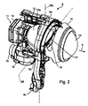
次に図2を参照して、ライトモジュール6、7の一方を一例として詳しく説明する。図2は、投影モジュールとして構成されたライトモジュール6を示している。他方のライトモジュール7も同様に構成されていてよく、または、たとえば反射モジュールとして構成されていてよい。ライトモジュール6は、水平方向の回転軸を定義する2つの軸受9bを介して、保持フレーム9aのそれぞれ向かい合う側で水平方向の軸9dを中心に回転可能なようにヘッドライトハウジング2に支承された外側の保持フレーム9aを含んでいる。水平方向の軸9dを中心としてライトモジュール6を旋回させることで、照明距離を変えることができる(いわゆるヘッドライトレンジコントロール、LWR)。ハウジング2に対して相対的に保持フレーム9aを位置調節するために、保持フレーム9aの1つの個所9cに、たとえば電磁石や電動モータの形態の操作部材が枢支されている。照明距離調節のための操作部材はヘッドライトハウジング2に取り付けられており、図2には示していない。
Next, with reference to FIG. 2, one of the light modules 6 and 7 will be described in detail as an example. FIG. 2 shows a light module 6 configured as a projection module. The other light module 7 may be configured in the same manner, or may be configured as a reflection module, for example. The light module 6 is supported by the headlight housing 2 through two bearings 9b defining a horizontal rotation axis so that the light module 6 can rotate around the
保持フレーム9aの内部にはリフレクタ10が配置されている。リフレクタ10aは、特に垂直方向の回転軸10bを中心として水平方向へ旋回可能なように、保持フレーム9aで支承されている。垂直方向の軸10bを中心としてリフレクタ10aを旋回させることで、発せられる光束の方向を水平方向に変えることができ、特に、ダイナミックコーナリングランプ機能を具体化することができる。リフレクタ10aの裏面には光源11が配置されており、リフレクタネック部12を介してリフレクタ10aに取り付けられている。光源11はガス放電ランプとして構成されており、特に、一体化された点火装置と一体化された制御装置とを備える型式D5Sのガス放電ランプとして構成されている。点火装置と制御装置はいずれも光源11の裏面で金属製にハウジング13に含まれているのが好ましい。光源11のガラス球(図示せず)が、リフレクタ10aの頂点に形成された開口部を通って、リフレクタ10aの内部に突入している。ガラス球の中では2つの電極の間でアークが点火され、ガス放電ランプ11の作動中に維持される。アークにより放出される光は、リフレクタ10aの内面の反射面により集束されて、実質的に光射出方向3へ反射される。リフレクタ10aで反射された光は、光路に配置された投影レンズ14により、車両前方の車道で特定の光分布を生成するために投影される。レンズ14は、リフレクタ10aの前側縁部に取り付けられたレンズホルダ15によって光路で保持される。
A reflector 10 is disposed inside the holding frame 9a. The reflector 10a is supported by a holding frame 9a so as to be able to turn in the horizontal direction, particularly about the vertical rotation shaft 10b. By turning the reflector 10a around the vertical axis 10b, the direction of the emitted light beam can be changed to the horizontal direction, and in particular, the dynamic cornering lamp function can be realized. A
リフレクタ10aと投影レンズ14の間には、リフレクタ10aで反射される光の一部を遮る絞り構造16が配置されている。絞り構造16の上側エッジ17が、光分布の実質的に水平方向の明暗境界を生成するために、投影レンズ14によって車道に結像される。絞り構造16の上側エッジ17の位置、ならびにその形状は、可変であるのが好ましい。上側エッジ17を昇降させることにより、結果として生じる光分布の明暗境界を昇降させることができる。上側エッジ17の形状を変更することで、光分布の明暗境界の形状を変えることができる。そのようにして、ライトモジュール6はたとえばロービームとハイビームの間で切換を行うことができる。さらに、ロービーム光分布とハイビーム光分布の中間にあるさまざまな光分布を具体化することができ、たとえば市街地用の光分布、幹線道路用の光分布、高速道路用の光分布などを具体化することができる。さらに、絞り構造16の有効な上側エッジ17の形状を変えることで、たとえば部分ハイビームの機能(対向または先行する交通関与者がハイビーム光分布で的確に照明される)や、マーキング光(車両前方の人物や対象物が、明暗境界の上方に配置された光束で的確に照明される)を具体化することができる。
Between the reflector 10a and the
垂直方向の回転軸を中心とするリフレクタ10aの旋回運動を具体化するために、および、絞り構造16の上側エッジ17の位置や形状を変えるために、ライトモジュール6の下側には2つの別々の操作部材が配置されており、そのうち一方の操作部材18だけが図2に見えている。操作部材18は、方向転換ギヤを含むギヤボックス19の外側にフランジ接合されている。操作部材18は、電動モータとして、特にステッピングモータとして構成されているのが好ましい。ギヤボックス19の中の方向転換ギヤは、モータ18の回転運動を、軸10bを中心とするリフレクタ10aの旋回運動のために、ならびに絞り構造16の上側エッジ17の位置および/または形状の変更のために、実質的に線形の操作運動に変換する。
In order to embody the swivel movement of the reflector 10a about the vertical rotation axis and to change the position and shape of the upper edge 17 of the diaphragm structure 16, two separate lower sides of the light module 6 are provided. These operating members are arranged, and only one of the operating
ガス放電ランプ11を備えるライトモジュール6は、それ自体としては交流電流による動作用として設計されている。したがってライトモジュール6の通常動作では、ライトモジュールは交流電流により作動する。しかし、ガス放電ランプ11は動作中に比較的多くの熱を放出するため、特に外気温が比較的高いときや冷房に不具合が生じたとき(たとえば車両エンジンおよびエンジンルーム全体の著しい加熱につながる中断のない長時間の走行の後に、車両を急に停車したとき)、照明装置1および/または制御装置8のライトモジュール6周辺の温度が許容される程度を超えて上昇し、そのために、ガス放電ランプ11の確実な信頼度の高い動作を保証できなくなるという事態が生じることがある。そのようなケースでは、損失出力の低減によって、放出される熱を引き下げなくてはならない。このことは、低い出力での、特に低い電流での、ガス放電ランプ11の作動によって実現される。この理由により、現代のガス放電ランプは、比較的長い時間帯にわたって減光することができるように、すなわち低い電流で作動できるように設計され、または制御されるのが望ましい。
The light module 6 including the
交流電流によるガス放電ランプ11の作動によって、特に、アークが間で点火されてランプ11の作動中に維持される電極の過熱を回避することができる。しかし、交流電流が低下すると電極が冷却されることになり、その電子の仕事関数が高くなり、または放出能力が低くなる。この理由により、交流電流動作で作動するガス放電ランプ11は限定的にしか減光可能でない。原則として、電流が低くなればなるほど、いっそう多くの再点火電圧を電流方向反転のために印加しなくてはならないと言える。つまり、ガス放電ランプの低い電流または出力は整流の問題につながり、それが光のちらつきとして知覚できるようになり、アークの消滅にまでつながる可能性がある。最近の型式のいくつかのガス放電ランプでは、出力削減に際して、クリティカルでない特定の電極温度を過ぎると、交流電流動作から直流電流動作へ切り換えることが可能であり、その際にランプ11を損傷させることがない。直流電流動作では大幅に低い出力が可能である。しかし、比較的長い直流電流動作を可能にすることは、追加のコストや費用を引き換えにせざるを得ない。
The operation of the
交流電流動作については、図3に符号HSL、HSR、LSL、LSRが付された、たとえばトランジスタの形態の制御可能な4つの半導体スイッチを含むHブリッジ回路(図3の符号25)が用いられるのが通常である。Hブリッジ回路25のそれぞれのブリッジ分枝の間(UoutLとUoutRの間)に、ガス放電ランプ11(GDL)が接続されている。点火器に基づくその誘導負荷は、符号Lzで示されている。Hブリッジ回路25は、中間回路直流電圧V+を、ブリッジ分枝に印加される矩形の交流電圧に変換する。半導体スイッチHSL、HSR、LSL、LSRおよびその制御エレクトロニクスの施工形態に応じて、程度の差こそあれ高いコストをかけて、連続的な直流電圧動作を維持することが可能である。
For AC current operation, an H-bridge circuit (
ドレインが正の中間回路電圧V+と接続された、nチャネルMOSFETまたはIGBTがハイサイドスイッチ(HSLまたはHSR)として使用される場合、ゲート電位は制御のために少なくとも閾値電圧Uthだけソース電位より高くなければならない。中間回路電圧V+はたとえば500Vである。ドレインSとソースSはオン状態(導通状態)のときにほぼ同一の電位になるので、ゲートGには、中間回路電圧V+より少なくとも閾値電圧Uthだけ高い電圧Vgが提供されなければならない。ゲートには、たとえば電圧Vg=510Vが提供される。 If an n-channel MOSFET or IGBT with its drain connected to the positive intermediate circuit voltage V + is used as a high-side switch (HSL or HSR), the gate potential must be higher than the source potential by at least the threshold voltage Uth for control. I must. Intermediate circuit voltage V + is, for example, 500V. Since the drain S and the source S have substantially the same potential in the on state (conductive state), the gate G must be supplied with a voltage Vg that is at least higher than the intermediate circuit voltage V + by the threshold voltage Uth. For example, a voltage Vg = 510V is provided to the gate.
Hブリッジ回路25のローサイドスイッチ(LSLまたはLSR)の制御は、図示している制御部20を介して直接行うことができる。Hブリッジ回路25のハイサイドスイッチ(HSLまたはHSR)の制御は、図3に示す例では、いわゆるブートストラップ回路24を介して行われる。回路24は、レベルシフタ23を介して制御されるゲートドライバ22を含んでいる。ゲートドライバ22の電圧供給部は、充電されたブートストラップコンデンサCbで構成されており、そのベースはハイサイドスイッチHSLのソースS(ローサイドスイッチLSLのドレインDおよびHブリッジ回路25の出力部UoutLに相当)につながれるとともに、その反対極は高圧ブートストラップダイオードDbを介して供給電圧Vsにつながれている。供給電圧Vsは、たとえば10Vである。図3では、左側のハイサイドスイッチHSLのためのブートストラップ回路24だけが示されている。その代替または追加として、当然ながら、相応のブートストラップ回路が他方のハイサイドスイッチHSRのために設けられていてもよい。ブートストラップ回路24を介してのハイサイドスイッチHSLのゲートGの制御に関するここでの説明で、これ以前またはこれ以後に行う記述は、相応のブートストラップ回路を介しての他方のハイサイドスイッチHSRのゲートGの制御についても相応の形で当てはまる。
Control of the low-side switch (LSL or LSR) of the H-
交流電流動作でローサイドスイッチLSLまたはLSRが制御されると(閉じられると、すなわち導通状態になると)、Hブリッジ回路25の出力部UoutLまたはUoutRはアースにつながれ、相応のハイサイドスイッチHSLまたはLSRについて設けられたブートストラップ回路24のブートストラップコンデンサCbは、当該回路24のブートストラップダイオードDbを介して、ほぼ供給電圧Vsの値まで充電される。Hブリッジ回路25が切り換えられるべきときには、ローサイドスイッチLSLまたはLSRがオフになり(開かれ、すなわち遮断状態になり)、次いでハイサイドスイッチHSLまたはHSRが制御される(導通状態になり、すなわち閉じられる)。それにより、ブートストラップコンデンサCbの電荷は、ゲートドライバ22を介して、ハイサイドスイッチHSLまたはHSRのゲートGとソースSの間で切り換えられ、それにより、ソースSの電位(Hブリッジ回路25の出力部UoutLまたはUoutRに相当)は中間回路電圧V+へと跳躍する。それにより、全体のブートストラップ回路24は電位に関して中間回路電圧V+(たとえば500V)にシフトされ、ブートストラップダイオードDbが阻止状態になり、ハイサイドスイッチHSLまたはHSRのゲート電圧Vgは中間回路電圧V+よりもブートストラップ電圧(ブートストラップコンデンサCbの電位)の分だけ高くなる。
When the low-side switch LSL or LSR is controlled by alternating current operation (closed, ie, becomes conductive), the output portion UoutL or UoutR of the H-
漏れ電流(ゲートドライバ22への供給+ダイオードDbの逆電流+レベルシフタ23の逆電流)によってブートストラップコンデンサCbが放電し、閾値電圧Uthを下回ることで、ハイサイドスイッチHSLまたはHSRは意図せず自動的に再びオフになる。すなわち、ハイサイドスイッチHSLまたはHSRを連続してオンのままに保つことができる最大時間は、ブートストラップコンデンサCbの容量、漏れ電流、供給電圧Vs、および半導体スイッチHSL、HSRの閾値電圧Uthから定義される。しかし、この最大時間はいかなるケースでも時間的に限られており、それによって交流電流動作の最低限の作業周波数が規定される。ガス放電ランプ11のこれよりも長い無制限の直流電流動作を可能にするためには、ブートストラップコンデンサCbから流出する電荷を補充しなければならず、このことは、図3に示す回路によって簡単かつ迅速に可能である。
The bootstrap capacitor Cb is discharged by the leakage current (supply to the
交流電流動作では、整流プロセス(Hブリッジ回路25の切換プロセス)のたびに、Hブリッジ回路25の出力電圧Uoutが同じ大きさ(中間回路電圧V+)になるように、ただし異なる正負記号で極反転するが、これは、左側と右側のブリッジ辺がそれぞれアースから正の中間回路電圧(+V+)へ、または正の中間回路電圧(+V+)からアースに切り換えられることによって行われる。それにより、ランプ電流I(Lz)は誘導負荷Lzに基づいて一定の時間定数をもつ指数関数に準じて低下していき、電流ゼロ通過に達して方向を切り換え、反対方向へ再び増加していく。
In the alternating current operation, the output voltage Uout of the
半導体スイッチHSL、HSR、LSL、LSRがオフ(遮断または高抵抗)になる瞬間に、点火インダクタンスLzがランプ電流を同じ方向でさらに駆動し、それによってブリッジ辺の出力電位が自動的に傾き、このことは、半導体スイッチHSL、HSR、LSL、LSRに並列につながれたフリーホイーリングダイオード26が電流を受け取るようになるまで、出力キャパシタンスが充電または放電されることによって行われる。最初に正の中間回路電圧V+へと切り換えられ、この段階中に、ブートストラップコンデンサCbが漏れ電流により電荷を失ったブリッジ辺は、ハイサイドスイッチHSLのターンオフによってアースへと傾き、それにより当該ブートストラップコンデンサCbを、ブートストラップダイオードDbを介して引き続き充電することができる。
At the moment when the semiconductor switches HSL, HSR, LSL, LSR are turned off (cut off or high resistance), the ignition inductance Lz further drives the lamp current in the same direction, so that the output potential at the bridge side automatically tilts. This is done by charging or discharging the output capacitance until the freewheeling
本発明は、ランプ電流I(Lz)が電流ゼロ通過に達する前に、コンデンサCbを時間的に再び充電できるという効果を利用するものであり、このことは数マイクロ秒後にすでに成立する可能性がある。つまりこのような効果は、直流電流動作でのブートストラップ回路24のコンデンサCbの再充電を可能にする。このときランプ電流I(Lz)は、交流電流動作で通常であるように、ゼロ通過に達した後に反対極の方向で再びオンになって全面的に整流されるのではなく、ゼロ通過に達する前に当初の方向で再びオンになり上昇していく。
The present invention makes use of the effect that the capacitor Cb can be recharged in time before the lamp current I (Lz) reaches the zero current passage, which may already hold after a few microseconds. is there. That is, such an effect makes it possible to recharge the capacitor Cb of the
本発明によると回路の直流電流動作のとき、Hブリッジ回路25の閉じている半導体スイッチHSL、LSRまたはHSR、LSLのうち少なくとも1つが時おり再充電プロセスの一環として一時的にターンオフされ(遮断され、すなわち開かれ)、少なくとも1つの半導体スイッチHSL、LSRの再充電プロセスは、Hブリッジ回路25のブリッジ分枝を介して流れる電流が0アンペアの値に達する前に終了する。再充電プロセスは5μs以下、特に2μs以下だけ続くのが好ましく、特別に好ましくは1μs以下である。連続する2回の再充電プロセスの間隔は、すなわち再充電の周波数は、ブートストラップ回路24のブートストラップコンデンサCbの電荷が、次回の再充電プロセスの前に、Hブリッジ回路25の少なくとも1つの閉じたハイサイドスイッチHSLまたはHSRを確実に制御して閉じた状態に保つために十分に大きいように選択される。連続する2回の再充電プロセスの間隔はミリ秒単位で選択されるのが好ましく、特に約2.5msである(約400Hzの再充電周波数)。
According to the present invention, when the circuit is in direct current operation, at least one of the closed semiconductor switches HSL, LSR or HSR, LSL of the H-
図3は、第1の実施形態に基づく本発明の回路を示している。この回路の信号推移が図4にプロットされており、および拡大して図5にプロットされている。図3から図5の第1の実施形態では、直流電流動作のときに、ハイサイドスイッチとして作用するHブリッジ回路25の閉じられた半導体スイッチHSLまたはHSRだけでなく、ローサイドスイッチとして作用するHブリッジ回路25の閉じられた半導体スイッチLSRまたはLSLも時おり一時的にターンオフされる。すなわち、負荷電流27を通す両方の半導体スイッチHSL、LSRまたはHSR、LSLがターンオフされる。それによりHブリッジ回路25が全面的にターンオフされる。このような機能は、本発明のために必要な迅速性を有する、現在普及している大半のドライバ22で具体化可能なので、この実施形態は、ガス放電ランプ11のための現在普及している制御回路によって、特に現在普及しているブートストラップ回路24によって、具体化することができる。
FIG. 3 shows a circuit of the present invention based on the first embodiment. The signal transition of this circuit is plotted in FIG. 4 and magnified in FIG. In the first embodiment of FIGS. 3 to 5, not only the closed semiconductor switch HSL or HSR of the H-
半導体スイッチHSL、LSRのターンオフにより、その前に操作されたハイサイドスイッチが配置されている側のブリッジ辺が、すなわち図3の例では左側のブリッジ辺が、自動的にアースへと傾く。しかし他方のブリッジ辺も、中間回路電圧V+へと自動的に傾く。それによりHブリッジ回路25の出力電圧Uoutが極反転する。したがって電流はフリーホイーリングダイオード28で、その前に無通電になっていた両方の半導体スイッチHSR、LSLを通って、正の中間電圧V+の出力コンデンサCdcへと流れ、これを上昇させる。図3では、負荷電流回路が矢印で図示されており、符号27およびフリーホイーリング回路が同じく矢印で図示されており、符号28が付されている。
When the semiconductor switches HSL and LSR are turned off, the bridge side on the side where the previously operated high-side switch is arranged, that is, the left-side bridge side in the example of FIG. 3 is automatically tilted to the ground. However, the other bridge side also automatically tilts to the intermediate circuit voltage V +. As a result, the output voltage Uout of the
直流電流動作でガス放電ランプ11が作動すると、点火インダクタンスLzによるフリーホイーリング電流28がランプ電圧そのものによって、およびこれに加えて当初は同じ大きさである中間回路電圧V+によって抑制される。しかし電圧V+は、この段階中にいっそう高くなりさえする。出力コンデンサCdcが充電されるからである。ランプ電流I(Lz)は、このような種類の回路では負の初期値に近づいていき、それに伴い、一定の時間後には電流ゼロ通過を通ることになる。これは交流電流動作のときの通常の整流に相当することになる。再充電プロセスの開始から、電流がゼロ通過に達するまでの時間中に、ブートストラップコンデンサCbが再充電される。この実施形態が特別に好ましいのは、高速のブートストラップDb(比較的短いパルスに基づく)または大きな点火インダクタンスLzが存在している場合である。このような態様は、十分に迅速に作動する、どのような通常の制御回路でも具体化することができる。
When the
図4aと図5aには、本発明に基づく直流電流動作中のランプ電流I(Lz)の推移が示されている。ランプ電流I(Lz)は、たとえば1.0μsのときの再充電プロセスの開始時における一例として300mAの当初の値から、再充電プロセスの時間中に、一例として3.0μsでの再充電プロセスの終了時における150mA以下の値まで低下することがわかる。そして再充電プロセスの終了後、ランプ電流I(Lz)は当初の300mAの値まで再び上昇していく。図5aでは再充電プロセスは、電流I(Lz)がゼロ通過に達するよりも明らかに前で終わっている。再充電プロセスの適時の終了がなされなければ、すなわち、半導体スイッチHSL、LSRの適時の再ターンオンがなされなければ、電流は(従来式の交流電流動作で普通であるように)ゼロ点に達し、他の半導体スイッチHSR、LSLがターンオンされたときに反転して、−300mAの方向に延びていくはずである。その様子が、図5aには破線で図示されている。 4a and 5a show the transition of the lamp current I (Lz) during direct current operation according to the invention. The lamp current I (Lz) is, for example, from the initial value of 300 mA at the start of the recharge process at 1.0 μs, during the time of the recharge process, by way of example of the recharge process at 3.0 μs. It turns out that it falls to the value of 150 mA or less at the time of completion. After the recharging process is completed, the lamp current I (Lz) rises again to the initial value of 300 mA. In FIG. 5a, the recharging process ends clearly before the current I (Lz) reaches zero passage. If the recharging process is not timely terminated, i.e., if the semiconductor switches HSL, LSR are not timely re-turned on, the current will reach zero (as is common with conventional AC current operation), When the other semiconductor switches HSR and LSL are turned on, they should reverse and extend in the direction of -300 mA. This is illustrated in broken lines in FIG. 5a.
図4bと図5bは、中間回路電圧V+の推移、ブリッジ回路25の左辺の出力電圧UoutLの推移、および、左と右のブリッジ辺のブリッジ・出力電圧差Uout=UoutL−UoutRの推移、すなわち、ブリッジ回路25のそれぞれのブリッジ分枝の間で低下する電圧の推移を示している。左のブリッジ辺の電位UoutLの推移は破線で図示されているのに対して、ブリッジ出力部Uoutの電位の推移は図5bに実線で図示されている。図からわかるように、Hブリッジ回路25の左辺は自動的にアース(0V)へと傾いており(破線)、Hブリッジ回路25の出力電圧は、負の中間回路電圧V+の値(本例では−60V)へと傾いている。再充電プロセス中のHブリッジ回路25の左辺または出力部における電位のそれぞれ異なる推移を、図5bに明らかに見ることができる。純粋な直流電流動作中には、すなわち再充電プロセスの範囲外では、電位の推移はほぼ合同である。図4bには、再充電プロセス中における中間回路電圧V+の若干の上昇(一点鎖線)を認めることができる。その要因は、出力コンデンサCdcの帰還に帰せられる。Hブリッジ回路25の出力Uoutは、再充電プロセス中、図示した例では中間回路電圧V+の負の値になっており、すなわち−60Vになっている。中間回路電圧V+の推移は、図4bと図5bに一点鎖線で図示されている。図4と図5のグラフでは、電圧の表記V(Ux,Uy)は、結節点xおよびyの電圧差Ux−Uyを意味しており、電圧の表記V(UoutL,UoutR)は、電圧差UoutL−UoutRすなわちUoutを意味している。電圧表記V(UgHSL,UoutL)は、電圧差UgHSL−UoutL=Ugate−Usource=Ugs(HSL)を意味している。
4b and 5b show the transition of the intermediate circuit voltage V +, the transition of the output voltage UoutL on the left side of the
図4cと図5cは、ハイサイドスイッチHSLのゲート・ソース電圧UgHSLについての、およびこれに伴ってターンオフプロセスの開始と終了についての、制御信号の推移を示している。ゲート制御信号は、t=1.0μsのときに下降エッジを有しており、t=3.0μsのときに上昇エッジを有している。さらに図4c、図5cは、ブートストラップコンデンサCbに印加される電圧Vb−UoutLの推移、およびこれに伴ってコンデンサCbの充電状態を示している。ハイサイドスイッチHSLのゲートGについての制御信号V(VGHSL−UoutL)は実線で図示されており、それに対してコンデンサCbに印加される電圧V(Vb−UoutL)の推移は破線で図示されている。図4cを参照すると明らかにわかるとおり、ブートストラップコンデンサCbの充電は、通常の直流電流動作中に、すなわち再充電プロセスの範囲外で、漏れ電流に基づいて連続的に減少していく。さらに明らかに見られるとおり、充電は再充電プロセス中に最短の時間内で再び当初の値まで上昇している。 FIGS. 4c and 5c show the transition of the control signal for the gate-source voltage UgHSL of the high-side switch HSL and accordingly the start and end of the turn-off process. The gate control signal has a falling edge when t = 1.0 μs and has a rising edge when t = 3.0 μs. 4c and 5c show the transition of the voltage Vb-UoutL applied to the bootstrap capacitor Cb and the state of charge of the capacitor Cb accompanying this. The control signal V (VGHSL-UoutL) for the gate G of the high side switch HSL is shown by a solid line, while the transition of the voltage V (Vb-UoutL) applied to the capacitor Cb is shown by a broken line. . As can be clearly seen with reference to FIG. 4c, the charging of the bootstrap capacitor Cb decreases continuously based on the leakage current during normal DC current operation, ie outside the range of the recharging process. As can also be seen clearly, the charging has risen again to the original value within the shortest time during the recharging process.
好ましい実施形態に基づいて本発明を具体化するためのさらに別の制御回路が、図6に示されている。相応の信号推移が図7にプロットされており、図8には拡大してプロットされている。この実施形態では直流電圧動作のときに時おり、Hブリッジ回路25のハイサイドスイッチとして作用する当初は閉じられた半導体スイッチHSLだけが一時的に切り換えられる。すなわち、導通状態のハイサイドスイッチだけがターンオフされる(開かれ、すなわち遮断される)。これは、左上から右下に向かって通電されるときには、左側のハイサイドスイッチHSLである(図6、負荷電流27参照)。これは、右上から左下に向かって通電されるときには、右側のハイサイドスイッチHSRである(図6には図示せず)。このブリッジ辺のローサイドスイッチLSRまたはLSLはターンオンされなくてよいが、ターンオンすることはできる。他方のブリッジ辺は接地されたままに保たれるので、ローサイドスイッチLSLまたはLSRはターンオンされたまま保たれる。それにより、ブートストラップコンデンサCbが充電されるべきブリッジ辺だけが自動的にアースへと傾く。したがって、Hブリッジ回路25の出力電圧Uoutは0Vである。それにより電流はフリーホイーリング28で、両方の下側のローサイドスイッチLSL、LSRだけを通って流れる。点火インダクタンスLzを通り、およびこれに伴ってHブリッジ回路25のブリッジ辺を介して流れる電流は、ランプ電圧そのものによってのみ抑制される。電流I(Lz)は、この回路形態では比較的ゆっくりと指数関数に従ってゼロ通過(0アンペア)に近づくことになるが、電流ゼロ通過を通ることはない。それによりこの実施形態では、ガス放電ランプ11でアークが消滅することになる程度までランプ電流が小さくなるまでに、図3から図5の第1の実施形態の場合よりも、ブートストラップコンデンサCbを再充電するために明らかに多くの時間が残される。第2の実施形態は、ハイサイドスイッチHSLまたはHSRを個別に制御することが可能であることを前提としており、このことは、現在市場で入手できるいくつかのHブリッジドライバ22またはブートストラップ回路24ではまだ意図されていない。
Yet another control circuit for embodying the present invention based on the preferred embodiment is shown in FIG. The corresponding signal transition is plotted in FIG. 7 and enlarged in FIG. In this embodiment, sometimes during DC voltage operation, only the initially closed semiconductor switch HSL acting as the high-side switch of the H-
図7と図8に示す信号推移は、第1の実施形態についての図4および図5と同じ量について図示したものである。明らかに見られるとおり、第2の実施形態では再充電プロセスは同じく1μsから3μsの間に作動し、すなわち合計で2μs続くものの、ランプ電流I(Lz)は第1の実施形態(図5a参照)よりも明らかにゆっくりと低下していく(図8a参照)。ランプ電流I(Lz)はターンオフプロセスの最後に、225mAを若干下回るところまでしか降下していないからである。図8bが示すように、ターンオフプロセスの開始時には、Hブリッジ回路25の左辺は自動的にアースへと傾く。再充電プロセスの終わりごろ、Hブリッジ回路25の出力Uoutはアース電位となっている。図7cと図8cにおける再充電プロセスのオンとオフ、ならびにブートストラップコンデンサCbの充電のプロセスは、基本的に、第1の実施形態(図4cおよび図5c参照)における再充電プロセスのオンとオフ、ならびにコンデンサCbの充電プロセスに対応している。
The signal transitions shown in FIGS. 7 and 8 are illustrated for the same amounts as in FIGS. 4 and 5 for the first embodiment. As can be clearly seen, in the second embodiment, the recharging process also operates between 1 μs and 3 μs, i.e. a total of 2 μs, but the lamp current I (Lz) is the first embodiment (see FIG. 5a). It decreases clearly more slowly (see FIG. 8a). This is because the lamp current I (Lz) drops only to a little below 225 mA at the end of the turn-off process. As shown in FIG. 8b, at the beginning of the turn-off process, the left side of the H-
ガス放電ランプ11については、再充電プロセスの時間は数マイクロ秒単位であり、それに対して、それぞれの再充電プロセスの間の純粋な直流電流段階はミリ秒単位である。すなわち、再充電パルスの反復率は、本来の交流電流動作のときの周波数であってよく、すなわち400Hz前後であってよい。このとき再充電パルス中における電流I(Lz)の一時的な急落は(図4aおよび図7a参照)、ライトモジュールから発せられる光では人間の目に見ることができない。本発明では、直流電流動作中に繰り返し一時的に再充電プロセスが実行されるが、それにもかかわらず、本発明ではガス放電ランプ11は直流電流動作で作動するのであって、交流電流動作のように作動するのではないと言うことができる。決定的に重要なのは、本発明では、交流電流動作のときに該当するような電流の整流(方向の変更)が、直流電流動作のときに行われないことである。
For
数マイクロ秒単位の短い再充電時間は、再充電プロセスを制御するマイクロコントローラが、マイクロ秒単位の非常に短い制御パルスを出力することができなければならないことを意味している。 A short recharge time of a few microseconds means that the microcontroller controlling the recharge process must be able to output very short control pulses in microseconds.
本発明の第1の実施形態では、25Wガス放電ランプを直流電流動作で15W以下にまで減光することができる。第2の実施形態、またはそのために意図される高速のドライバ22および個々の半導体スイッチの別々の制御可能性を、新たに開発されるべきHブリッジモジュールに組み込むことができるであろう。その場合には、25Wランプを10W以下の出力まで抑制制御することが考えられる。
In the first embodiment of the present invention, a 25 W gas discharge lamp can be dimmed to 15 W or less by direct current operation. The second embodiment, or the
本発明は、出力低減のために直流電流動作が意図されるガス放電ランプで適用することができる。このことは特に、現在開発が進んでいる型式D5の25Wガス放電ランプで該当する場合がある。内蔵された点火装置と内蔵された制御装置とを有する25Wガス放電ランプは、現在、「D5S」の名称で流通している。さらに本発明により、任意の型式のガス放電ランプで、アークの点火後に電極の加熱のために必要となる、必要な比較的長い両方の最初の直流電圧段階を延長し、または、非常に小型のブートストラップコンデンサCbによって行うことが可能であり、すなわち、これを設計形態/容量の点から削減することが可能である。あるいは当然ながら本発明により、切換式に制御されるべき、ブートストラップHブリッジ回路の適用が考えられる、たとえば電動モータや電磁石のような他の誘導負荷を、直流電流により作動させることもできる。
The present invention can be applied to gas discharge lamps intended for direct current operation to reduce output. This may be especially the case with the type D5 25W gas discharge lamp currently under development. A 25 W gas discharge lamp having a built-in ignition device and a built-in control device is currently distributed under the name “D5S”. Furthermore, according to the present invention, in any type of gas discharge lamp, both the required relatively long initial DC voltage steps required for electrode heating after arc ignition are extended or very small This can be done with a bootstrap capacitor Cb, i.e. it can be reduced in terms of design / capacitance. Or, of course, other inductive loads, such as electric motors or electromagnets, for example, which can be applied to the bootstrap H-bridge circuit, which should be controlled in a switchable manner, can also be activated by direct current.
Claims (16)
前記光源(11)は、
誘導負荷(Lz)を有しており、
4つの半導体スイッチ(HSL、HSR、LSL、LSR)を有する電気的なHブリッジ回路(25)のそれぞれのブリッジ分枝の間に配置されており、
交流電流動作のときに前記Hブリッジ回路(25)を介して交流電流の供給を受け、
前記Hブリッジ回路(25)の上側に配置された両方の半導体スイッチ(HSL、HSR)はブートストラップコンデンサ(Cb)をそれぞれ有するブートストラップ回路(24)を通じてそれぞれ制御される、
そのような方法において、
直流電流動作のときに前記Hブリッジ回路(25)の閉じた半導体スイッチ(HSL、LSR;HSR、LSL)のうち少なくとも1つが再充電プロセスのために時おり一時的にオフにされ、再充電プロセスの終了時に再びオンになり、
前記再充電プロセスは、前記Hブリッジ回路のブリッジ分枝を介して流れる電流(I(Lz))が0アンペアの値に達するよりも前に終了すること、を特徴とする方法。 A method of operating a light source (11) of an automobile headlight (1) provided for operation by alternating current as such by direct current,
The light source (11)
Has an inductive load (Lz),
Arranged between each bridge branch of an electrical H-bridge circuit (25) having four semiconductor switches (HSL, HSR, LSL, LSR);
When alternating current is operated, supply of alternating current is received via the H bridge circuit (25),
Both semiconductor switches (HSL, HSR) arranged on the upper side of the H bridge circuit (25) are respectively controlled through a bootstrap circuit (24) having a bootstrap capacitor (Cb).
In such a way,
During DC current operation, at least one of the closed semiconductor switches (HSL, LSR; HSR, LSL) of the H-bridge circuit (25) is sometimes temporarily turned off for the recharging process, and the recharging process Will turn on again at the end of
The method wherein the recharging process ends before the current (I (Lz)) flowing through the bridge branch of the H-bridge circuit reaches a value of 0 amperes.
前記光源(11)は誘導負荷(Lz)を有しており、
前記電気回路は、
交流電流動作のときに前記光源(11)に交流電流を供給するための4つの半導体スイッチ(HSL、HSR、LSL、LSR)を有する電気的なHブリッジ回路(25)を含んでおり、前記光源(11)は前記Hブリッジ回路(25)のそれぞれのブリッジ分枝の間に配置されており、
ブートストラップコンデンサ(Cb)をそれぞれ有するブートストラップ回路(24)を含んでおり、前記ブートストラップ回路(24)は前記Hブリッジ回路(25)の上側に配置された両方の半導体スイッチ(HSL、HSR)のうちの一方をそれぞれ制御するためのものである、
そのような電気回路において、
前記電気回路は直流電流動作のときに前記Hブリッジ回路(25)の閉じた半導体スイッチ(HSL、LSR;HSR、LSL)のうち少なくとも1つの一時的なターンオフと再度のターンオンによって前記ブートストラップコンデンサ(Cb)を時おり再充電することが可能であり、
再充電プロセスの時間は、前記Hブリッジ回路(25)のブリッジ分枝を通って流れる電流(I(Lz))が0アンペアの値に達するよりも前に再充電プロセスが終了するように設定されていること、を特徴とする電気回路。 An electric circuit for operating a light source (11) of an automobile headlight (1) provided for operation by an alternating current as such by a direct current,
The light source (11) has an inductive load (Lz),
The electrical circuit is
An electrical H-bridge circuit (25) having four semiconductor switches (HSL, HSR, LSL, LSR) for supplying an alternating current to the light source (11) during an alternating current operation; (11) is arranged between each bridge branch of the H-bridge circuit (25),
The bootstrap circuit (24) includes a bootstrap capacitor (Cb). The bootstrap circuit (24) includes both semiconductor switches (HSL, HSR) disposed on the upper side of the H bridge circuit (25). For controlling one of each,
In such an electrical circuit,
When the electric circuit is operated at a direct current, the bootstrap capacitor (HSL, LSR; HSR, LSL) is temporarily turned off and turned on again in the closed semiconductor switches (HSL, LSR; HSR, LSL) of the H bridge circuit (25). Cb) it is possible that the recharging time to time,
The time of the recharging process is set so that the recharging process is terminated before the current (I (Lz)) flowing through the bridge branch of the H-bridge circuit (25) reaches a value of 0 amperes. An electrical circuit characterized by that.
Applications Claiming Priority (3)
| Application Number | Priority Date | Filing Date | Title |
|---|---|---|---|
| DE102010048604.3 | 2010-10-15 | ||
| DE102010048604A DE102010048604A1 (en) | 2010-10-15 | 2010-10-15 | Method and electrical circuit for operating a light source of a motor vehicle headlight with direct current, and light module of a motor vehicle headlight with such a circuit and motor vehicle headlights with such a light module |
| PCT/EP2011/067694 WO2012049152A2 (en) | 2010-10-15 | 2011-10-11 | Method and electrical circuit for operating a light source of a motor vehicle headlight with direct current, and light module of a motor vehicle headlight comprising such a circuit and motor vehicle headlight comprising such a light module |
Publications (2)
| Publication Number | Publication Date |
|---|---|
| JP2013539902A JP2013539902A (en) | 2013-10-28 |
| JP5777719B2 true JP5777719B2 (en) | 2015-09-09 |
Family
ID=44800029
Family Applications (1)
| Application Number | Title | Priority Date | Filing Date |
|---|---|---|---|
| JP2013533177A Active JP5777719B2 (en) | 2010-10-15 | 2011-10-11 | Method and electric circuit for operating the light source of an automobile headlight by direct current, an automobile headlight light module comprising such a circuit, and an automobile headlight comprising such a light module |
Country Status (7)
| Country | Link |
|---|---|
| US (1) | US8878446B2 (en) |
| EP (1) | EP2628366B1 (en) |
| JP (1) | JP5777719B2 (en) |
| KR (1) | KR20130138257A (en) |
| CN (1) | CN103238378B (en) |
| DE (1) | DE102010048604A1 (en) |
| WO (1) | WO2012049152A2 (en) |
Families Citing this family (4)
| Publication number | Priority date | Publication date | Assignee | Title |
|---|---|---|---|---|
| DE102010018325A1 (en) * | 2010-04-27 | 2011-10-27 | Automotive Lighting Reutlingen Gmbh | Method and control circuit for the start of a gas discharge lamp |
| JP6396160B2 (en) * | 2014-10-02 | 2018-09-26 | 株式会社小糸製作所 | Vehicle lamp and its lighting circuit |
| CN109862655A (en) * | 2018-10-17 | 2019-06-07 | 矽力杰半导体技术(杭州)有限公司 | Integrated circuit, Dimmable LED driving circuit and its driving method |
| JP7240856B2 (en) * | 2018-11-13 | 2023-03-16 | 株式会社小糸製作所 | Lamp controller and lamp assembly |
Family Cites Families (10)
| Publication number | Priority date | Publication date | Assignee | Title |
|---|---|---|---|---|
| DE10220509A1 (en) * | 2002-05-08 | 2003-11-20 | Philips Intellectual Property | Method and circuit arrangement for operating a high-pressure gas discharge lamp |
| US8912174B2 (en) | 2003-04-16 | 2014-12-16 | Mylan Pharmaceuticals Inc. | Formulations and methods for treating rhinosinusitis |
| CN101427610A (en) * | 2005-03-04 | 2009-05-06 | 国际整流器公司 | Automotive high intensity discharge lamp ballast circuit |
| JP4687173B2 (en) * | 2005-03-18 | 2011-05-25 | パナソニック電工株式会社 | Discharge lamp lighting device and vehicle lamp |
| ATE496517T1 (en) * | 2006-02-20 | 2011-02-15 | Koninkl Philips Electronics Nv | METHOD AND DRIVE DEVICE FOR OPERATING A GAS DISCHARGE LAMP |
| US7884555B2 (en) * | 2006-05-01 | 2011-02-08 | Mitsubishi Electric Corporation | Discharge lamp ballast apparatus |
| US8093834B2 (en) * | 2007-02-06 | 2012-01-10 | International Rectifier Corporation | Automotive HID headlamp ballast control IC |
| US8232744B2 (en) * | 2008-01-23 | 2012-07-31 | Osram Ag | Method for the operation of and circuit arrangement for light sources |
| JP4692611B2 (en) * | 2008-11-27 | 2011-06-01 | ウシオ電機株式会社 | High pressure discharge lamp lighting device and projector |
| JP5262647B2 (en) * | 2008-12-05 | 2013-08-14 | 岩崎電気株式会社 | High pressure discharge lamp lighting device, projector, and high pressure discharge lamp starting method |
-
2010
- 2010-10-15 DE DE102010048604A patent/DE102010048604A1/en not_active Ceased
-
2011
- 2011-10-11 KR KR1020137012023A patent/KR20130138257A/en not_active Application Discontinuation
- 2011-10-11 EP EP11769856.3A patent/EP2628366B1/en active Active
- 2011-10-11 US US13/879,567 patent/US8878446B2/en active Active
- 2011-10-11 WO PCT/EP2011/067694 patent/WO2012049152A2/en active Application Filing
- 2011-10-11 CN CN201180049376.6A patent/CN103238378B/en active Active
- 2011-10-11 JP JP2013533177A patent/JP5777719B2/en active Active
Also Published As
| Publication number | Publication date |
|---|---|
| US8878446B2 (en) | 2014-11-04 |
| WO2012049152A3 (en) | 2012-08-30 |
| CN103238378A (en) | 2013-08-07 |
| KR20130138257A (en) | 2013-12-18 |
| DE102010048604A1 (en) | 2012-04-19 |
| EP2628366A2 (en) | 2013-08-21 |
| CN103238378B (en) | 2014-12-31 |
| WO2012049152A2 (en) | 2012-04-19 |
| JP2013539902A (en) | 2013-10-28 |
| US20140145639A1 (en) | 2014-05-29 |
| EP2628366B1 (en) | 2014-10-01 |
Similar Documents
| Publication | Publication Date | Title |
|---|---|---|
| US9648679B2 (en) | Vehicle lamp and lighting circuit thereof | |
| JP6751707B2 (en) | Vehicle lighting | |
| CN108966409B (en) | Lighting circuit for vehicle lamp and light source | |
| US8172442B2 (en) | Vehicle lamp | |
| KR102108253B1 (en) | Vehicular lamp | |
| JP2016199083A (en) | Lighting fixture for vehicle | |
| JP2009134933A (en) | Led lighting device, and headlight for vehicle | |
| JP5777719B2 (en) | Method and electric circuit for operating the light source of an automobile headlight by direct current, an automobile headlight light module comprising such a circuit, and an automobile headlight comprising such a light module | |
| JP7149787B2 (en) | VEHICLE LAMP AND CONTROL METHOD THEREOF | |
| JP6101587B2 (en) | Vehicle headlamp | |
| JP2014031157A (en) | Vehicular lamp | |
| CN108882438A (en) | Driving circuit, Vehicular lamp | |
| JP6521693B2 (en) | Vehicle lighting system | |
| JP5422068B2 (en) | LED lighting device and vehicle headlamp | |
| JP4012755B2 (en) | Vehicle lighting device | |
| JP5551545B2 (en) | Discharge lamp lighting circuit | |
| JP2004311215A (en) | Discharge lamp lighting device | |
| JPH0338441A (en) | Head lamp for vehicle | |
| JPS5855015B2 (en) | Brightness level adjustment device | |
| US8154208B2 (en) | Method of supplying power to an automobile headlight lamp and headlight using that method | |
| JP6889612B2 (en) | Lighting circuit for vehicle lamps and light sources | |
| KR20060107059A (en) | A headlight for automobile having with gas discharging lamp | |
| JPH07246873A (en) | Headlight for vehicle | |
| KR100699794B1 (en) | Discharge Lamp Ballast Having Illumination Function | |
| KR200291103Y1 (en) | Arc discharge lamp device for vehicle |
Legal Events
| Date | Code | Title | Description |
|---|---|---|---|
| A621 | Written request for application examination |
Free format text: JAPANESE INTERMEDIATE CODE: A621 Effective date: 20140808 |
|
| A977 | Report on retrieval |
Free format text: JAPANESE INTERMEDIATE CODE: A971007 Effective date: 20150408 |
|
| A131 | Notification of reasons for refusal |
Free format text: JAPANESE INTERMEDIATE CODE: A131 Effective date: 20150414 |
|
| A521 | Request for written amendment filed |
Free format text: JAPANESE INTERMEDIATE CODE: A523 Effective date: 20150521 |
|
| TRDD | Decision of grant or rejection written | ||
| A01 | Written decision to grant a patent or to grant a registration (utility model) |
Free format text: JAPANESE INTERMEDIATE CODE: A01 Effective date: 20150616 |
|
| A61 | First payment of annual fees (during grant procedure) |
Free format text: JAPANESE INTERMEDIATE CODE: A61 Effective date: 20150707 |
|
| R150 | Certificate of patent or registration of utility model |
Ref document number: 5777719 Country of ref document: JP Free format text: JAPANESE INTERMEDIATE CODE: R150 |
|
| R250 | Receipt of annual fees |
Free format text: JAPANESE INTERMEDIATE CODE: R250 |
|
| R250 | Receipt of annual fees |
Free format text: JAPANESE INTERMEDIATE CODE: R250 |
|
| R250 | Receipt of annual fees |
Free format text: JAPANESE INTERMEDIATE CODE: R250 |
|
| R250 | Receipt of annual fees |
Free format text: JAPANESE INTERMEDIATE CODE: R250 |
|
| R250 | Receipt of annual fees |
Free format text: JAPANESE INTERMEDIATE CODE: R250 |
|
| R250 | Receipt of annual fees |
Free format text: JAPANESE INTERMEDIATE CODE: R250 |