JP5777317B2 - Medical image display device - Google Patents
Medical image display device Download PDFInfo
- Publication number
- JP5777317B2 JP5777317B2 JP2010237804A JP2010237804A JP5777317B2 JP 5777317 B2 JP5777317 B2 JP 5777317B2 JP 2010237804 A JP2010237804 A JP 2010237804A JP 2010237804 A JP2010237804 A JP 2010237804A JP 5777317 B2 JP5777317 B2 JP 5777317B2
- Authority
- JP
- Japan
- Prior art keywords
- interest
- cross
- dimensional
- medical image
- unit
- Prior art date
- Legal status (The legal status is an assumption and is not a legal conclusion. Google has not performed a legal analysis and makes no representation as to the accuracy of the status listed.)
- Active
Links
- 230000033001 locomotion Effects 0.000 claims description 40
- 238000005259 measurement Methods 0.000 claims description 9
- 229960001716 benzalkonium Drugs 0.000 claims 1
- CYDRXTMLKJDRQH-UHFFFAOYSA-N benzododecinium Chemical compound CCCCCCCCCCCC[N+](C)(C)CC1=CC=CC=C1 CYDRXTMLKJDRQH-UHFFFAOYSA-N 0.000 claims 1
- 230000000241 respiratory effect Effects 0.000 description 25
- 210000004204 blood vessel Anatomy 0.000 description 18
- 238000012545 processing Methods 0.000 description 18
- 230000029058 respiratory gaseous exchange Effects 0.000 description 16
- 238000000034 method Methods 0.000 description 13
- 230000008569 process Effects 0.000 description 10
- 238000010586 diagram Methods 0.000 description 8
- 230000002441 reversible effect Effects 0.000 description 8
- 206010028980 Neoplasm Diseases 0.000 description 7
- 230000008859 change Effects 0.000 description 7
- 238000002591 computed tomography Methods 0.000 description 6
- 238000003384 imaging method Methods 0.000 description 6
- 238000007781 pre-processing Methods 0.000 description 6
- 210000000709 aorta Anatomy 0.000 description 4
- 238000001514 detection method Methods 0.000 description 4
- 238000002595 magnetic resonance imaging Methods 0.000 description 4
- 210000000621 bronchi Anatomy 0.000 description 3
- 238000004891 communication Methods 0.000 description 3
- 238000013500 data storage Methods 0.000 description 3
- 230000010349 pulsation Effects 0.000 description 3
- 208000031481 Pathologic Constriction Diseases 0.000 description 2
- 230000004913 activation Effects 0.000 description 2
- 238000003491 array Methods 0.000 description 2
- 238000006243 chemical reaction Methods 0.000 description 2
- 230000008602 contraction Effects 0.000 description 2
- 238000013480 data collection Methods 0.000 description 2
- 238000003745 diagnosis Methods 0.000 description 2
- 230000000694 effects Effects 0.000 description 2
- 230000005484 gravity Effects 0.000 description 2
- 210000004072 lung Anatomy 0.000 description 2
- 230000000737 periodic effect Effects 0.000 description 2
- 208000037804 stenosis Diseases 0.000 description 2
- 230000036262 stenosis Effects 0.000 description 2
- 206010006482 Bronchospasm Diseases 0.000 description 1
- 210000001015 abdomen Anatomy 0.000 description 1
- 230000003187 abdominal effect Effects 0.000 description 1
- 239000006096 absorbing agent Substances 0.000 description 1
- 230000005540 biological transmission Effects 0.000 description 1
- 230000007885 bronchoconstriction Effects 0.000 description 1
- 238000004364 calculation method Methods 0.000 description 1
- 210000004351 coronary vessel Anatomy 0.000 description 1
- 238000002059 diagnostic imaging Methods 0.000 description 1
- 230000010339 dilation Effects 0.000 description 1
- 238000006073 displacement reaction Methods 0.000 description 1
- 238000005516 engineering process Methods 0.000 description 1
- 238000000605 extraction Methods 0.000 description 1
- 230000006870 function Effects 0.000 description 1
- 230000010354 integration Effects 0.000 description 1
- 239000003550 marker Substances 0.000 description 1
- 239000002184 metal Substances 0.000 description 1
- 238000012986 modification Methods 0.000 description 1
- 230000004048 modification Effects 0.000 description 1
- 230000003287 optical effect Effects 0.000 description 1
- 210000005259 peripheral blood Anatomy 0.000 description 1
- 239000011886 peripheral blood Substances 0.000 description 1
- 230000002093 peripheral effect Effects 0.000 description 1
- 238000001959 radiotherapy Methods 0.000 description 1
- 230000008929 regeneration Effects 0.000 description 1
- 238000011069 regeneration method Methods 0.000 description 1
- 230000003252 repetitive effect Effects 0.000 description 1
- 230000035945 sensitivity Effects 0.000 description 1
- 238000004904 shortening Methods 0.000 description 1
- 230000002123 temporal effect Effects 0.000 description 1
- 230000000007 visual effect Effects 0.000 description 1
Images


Description
本発明の実施形態は、医用画像表示装置に関する。 Embodiments described herein relate generally to a medical image display apparatus.
近年の医用画像装置は例えば超音波診断装置、X線コンピュータ断層撮影装置(CT)、磁気共鳴映像装置(MRI)では画像の基礎となるデータを繰り返し収集することが可能である。ここではX線コンピュータ断層撮影装置として説明する。繰り返し収集された投影データから、連続する複数のボリュームデータファイルをコーンビーム再構成法などで再構成し、これらボリュームデータファイルからMPR(断面変化)処理等により生成した断面画像を動画として表示することができる。 In recent medical imaging apparatuses, for example, an ultrasonic diagnostic apparatus, an X-ray computed tomography apparatus (CT), and a magnetic resonance imaging apparatus (MRI) can repeatedly collect data that is the basis of an image. Here, an X-ray computed tomography apparatus will be described. To reconstruct multiple continuous volume data files from repetitively collected projection data using cone beam reconstruction method, etc., and to display the cross-sectional images generated from these volume data files by MPR (cross-section change) processing as moving images Can do.
しかし、呼吸動や拍動等によって観察したい領域が断面から外れてしまいうことがあった。例えば呼吸動による大動脈と腫瘍の癒着観察を診断目的としているとき、呼吸動による腫瘍や大動脈の3次元的な移動により画像から癒着箇所を確認できなくなってしまうことがあった。 However, the region to be observed sometimes deviated from the cross section due to respiratory movement or pulsation. For example, when the observation of adhesion between an aorta and a tumor due to respiratory motion is intended for diagnosis, the adhesion site may not be confirmed from the image due to the three-dimensional movement of the tumor or aorta due to respiratory motion.
目的は、呼吸動や拍動の影響による関心部位の移動軌跡を定量的且つ視覚的に提供することにある。 The purpose is to provide quantitatively and visually the movement trajectory of the region of interest due to the influence of respiratory motion and pulsation.
本実施形態に係る医用画像表示装置は、被検体の生理的運動に関する複数の位相に係る複数のボリュームデータファイルを用いて前記位相ごとに関心点の3次元位置を特定する位置特定部と、前記特定された関心点の3次元位置に基づいて、前記複数の位相にわたる前記関心点の移動距離を計測する距離計測部と、前記特定された複数の3次元位置に基づいて、前記関心点にそれぞれ対応する前記生理的運動に伴う移動軌跡に関する3次元マップと2次元マップとを発生するマップ発生部と、前記3次元マップと前記2次元マップとを表示する表示部と、を具備する。
The medical image display apparatus according to the present embodiment includes a position specifying unit that specifies a three-dimensional position of a point of interest for each phase using a plurality of volume data files related to a plurality of phases related to a physiological motion of the subject, A distance measuring unit that measures a movement distance of the point of interest across the plurality of phases based on the identified three-dimensional position of the point of interest; and a point of interest based on the plurality of identified three-dimensional positions, respectively. A map generation unit that generates a three-dimensional map and a two-dimensional map related to the movement trajectory associated with the corresponding physiological movement; and a display unit that displays the three-dimensional map and the two-dimensional map .
以下、図面を参照しながら本実施形態に係わる医用画像表示装置を説明する。なお、医用画像表示装置は、X線コンピュータ断層撮影装置、磁気共鳴映像装置(MRI)、超音波診断装置、X線診断装置などの被検体の3次元領域に関するデータを連続的に繰り返し収集可能な医用画像発生装置に適合する。本実施形態に係わる医用画像表示装置は、これら医用画像発生装置に組み込まれ、又は単独で機能する。単独で機能するとき、本実施形態に係わる医用画像表示装置は、LANなどの電気的通信回線に接続され、電気的通信回線を介して病院内又は外部の医用画像補間通信システム(PACS)から表示対象データを受信する。ここでは、本実施形態に係わる医用画像表示装置は、X線コンピュータ断層撮影装置に組み込まれたものとして説明する。 The medical image display apparatus according to this embodiment will be described below with reference to the drawings. The medical image display apparatus can continuously and repeatedly collect data relating to a three-dimensional region of a subject such as an X-ray computed tomography apparatus, a magnetic resonance imaging apparatus (MRI), an ultrasonic diagnostic apparatus, and an X-ray diagnostic apparatus. Suitable for medical image generator. The medical image display apparatus according to the present embodiment is incorporated in these medical image generation apparatuses or functions alone. When functioning alone, the medical image display apparatus according to the present embodiment is connected to an electrical communication line such as a LAN, and displays from a medical image interpolation communication system (PACS) inside or outside the hospital via the electrical communication line. Receive target data. Here, the medical image display apparatus according to the present embodiment will be described as being incorporated in an X-ray computed tomography apparatus.
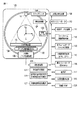
図1に、本実施形態に係る医用画像表示装置を装備したX線コンピュータ断層撮影装置の構成をブロック図により示している。架台部100は、回転自在に支持される回転フレーム102を有する。回転フレーム102の回転中心軸をZ軸、水平方向をX軸、垂直方向をY軸として説明する。架台駆動部107はホストコントローラ110の制御の下で回転フレーム102を回転駆動するための駆動信号を発生する。回転フレーム102にはコーンビーム形X線管101と2次元検出器(エリア検出器とも呼ばれる)103とがZ軸を中心とした撮影領域Sを挟んで対向して搭載される。撮影領域Sには図示しないが寝台の天板に載置された被検体が配置される。被検体はその体軸がZ軸に略一致するように載置される。高電圧発生器109はホストコントローラ110の制御の下でX線管101に管電流を供給し、また高電圧を印加する。それによりX線管101の焦点Fから四角錐形のX線が発生される。2次元検出器103は、複数のX線検出素子列を有する。複数のX線検出素子列はZ軸方向に並列される。各X線検出素子列はX線焦点Fを中心として円弧状に配列される。2次元検出器103には一般的にDAS(data acquisition system) と呼ばれているデータ収集装置104が接続される。
FIG. 1 is a block diagram showing the configuration of an X-ray computed tomography apparatus equipped with a medical image display apparatus according to this embodiment. The
データ収集装置104には、2次元検出器103の各チャンネルの電流信号を電圧に変換するI−V変換器と、この電圧信号をX線の曝射周期に同期して周期的に積分する積分器と、この積分器の出力信号を増幅するアンプと、このプリアンプの出力信号をディジタル信号に変換するアナログ・ディジタル・コンバータとが、チャンネルごとに設けられている。
The
データ収集装置104の出力には光学的又は磁気的要素を媒介させる非接触データ伝送装置105を介して前処理装置106が接続される。前処理装置106は、データ収集装置104で検出されたデータに対して、チャンネル間の感度不均一を補正し、またX線強吸収体、主に金属部による極端な信号強度の低下又は信号脱落を補正する等の前処理を実行する。前処理装置106で前処理を受けたデータ(投影データ)は投影データ記憶部112に記憶される。
A
本実施形態では、ホストコントローラ110の制御のもと、いわゆる4次元ダイナミックスキャンが実行される。4次元ダイナミックスキャンでは、予め指定された撮影期間中にわたって回転フレーム102がX線管101と2次元検出器103とともに被検体の周囲を連続的に回転される。撮影期間中にはX線管101からX線が連続的又はパルス的に発生され、2次元検出器103ではX線検出が繰り返される。なおX線管101が360°又は(180°+ファン角)を回転する周期をスキャン周期(第1の周期)と称する。この360°又は(180°+ファン角)の角度範囲分の投影データから単一のボリュームデータファイルが再構成される。ファン角とはX線焦点を中心としたXY面内でのX線の拡がり角である。
In the present embodiment, so-called four-dimensional dynamic scan is executed under the control of the host controller 110. In the four-dimensional dynamic scan, the rotating
コーンビーム再構成処理部116は、ホストコントローラ110の制御のもとで投影データ記憶部112に記憶された投影データに基づいて、例えばコーンビーム再構成法によりCT値分布を3次元座標系で表現してなる複数のボリュームデータファイルを再構成する。上述の通り、各ボリュームデータファイルは、360°又は(180°+ファン角)の角度範囲分の投影データから再構成される。複数のボリュームデータファイルは、それぞれの再構成に用いる投影データの角度範囲が例えば30°ずつシフトされる。それにより、複数のボリュームデータファイルそれぞれが対応する時刻、典型的にはそれぞれの再構成に用いた投影データの角度範囲の略中心角度の投影データの収集時刻は30°の回転に要する時間ずつシフトする。つまり、図2に示すように、一連を構成する複数のボリュームデータファイルはスキャン周期(第1の周期)より短い時間間隔(第2の周期)の時間分解能で再構成される。一連のボリュームデータファイルはボリュームデータファイル記憶部113に記憶される。
The cone beam
断面画像発生部115は、図3に示すように、表示部(ディスプレイ)117への表示に適合するいわゆるMPR処理(断面変換処理)又はCPR処理(曲断面変換処理)により、一連を構成する複数のボリュームデータファイルからそれぞれ対応する一連を構成する複数の断面画像を発生する。発生された複数の断面画像のデータはボリュームデータファイル記憶部113に記憶される。各断面位置及び断面厚は、複数のボリュームデータファイルに対して個々に断面位置決定部125により決定される。断面位置及び断面厚の決定に関する詳細は後述する。
As shown in FIG. 3, the cross-sectional
再生コントローラ118は、ボリュームデータファイル記憶部113から一連の断面画像のデータの読み出しを制御することにより、ボリュームデータファイル記憶部113に記憶された一連の断面画像を動画として表示部117に表示させる。
The
この再生表示は被検体の周期的な生理運動に関連付けられる。周期的な生理運動は、典型的には呼吸運動又は心拍運動である。本実施形態では、呼吸運動と心拍運動とのいずれにも適用することができる。ここでは呼吸運動として説明する。被検体の呼吸運動は、例えば呼吸センサ120により測定される。周知の通り、呼吸動作は、横隔膜の往復運動に伴なう肺野の拡張収縮である。肺野の拡張収縮に伴って腹部が前後に往復移動をする。呼吸センサ120は、例えばレーザ測長技術を用いて被検体の腹部表面と外部固定点(レーザ照射位置)との間の距離を呼吸インデックスとして繰り返し計測する。この距離の時間的変化は、被検体の呼吸の状態(呼吸位相)の変化を反映している。最大値/最小値特定部123は、撮影期間中の呼吸インデックスの変化から、最大値と最小値とを特定する。例えば呼吸インデックスが最小値を示す時刻は呼気ボトム時刻を表し、呼吸インデックスが最大値を示す時刻は吸気ピーク時刻を表している。呼気ボトム時刻から吸気ピーク時刻までの期間は、呼吸周期の略半周期を表している。
This reproduction display is related to the periodic physiological movement of the subject. The periodic physiological movement is typically a respiratory movement or a heartbeat movement. In the present embodiment, the present invention can be applied to both respiratory exercise and heartbeat exercise. Here, it demonstrates as a respiratory exercise. The respiratory motion of the subject is measured by the
再生コントローラ118は、ボリュームデータファイル記憶部113に記憶されている一連の断面画像から、呼気ボトム時刻から吸気ピーク時刻呼吸までの期間に対応する複数の断面画像を再生対象画像として特定する。再生コントローラ118は、再生対象画像として特定した一連の断面画像を繰り返し再生する。特に再生コントローラ118は、図4に示すように、一連の断面画像を、それぞれが対応する時刻の順番に沿って順方向に実時間再生し(順方向再生)、それに続いて、それぞれが対応する時刻の順番とは逆行する時間経過で逆方向に実時間再生され(逆方向再生)、このように順方向再生と逆方向再生とが交互に繰り返される。つまり再生方向が交互に転換される。この呼吸の略半周期に限定して交互再生される動画は、1呼吸期間の動画の繰り返し再生に近似的である。略半周期の期間に限定した交互再生では、交互再生の境界フレーム間で呼吸位相がほぼ同一になり、従って交互再生の境界フレーム間では当然にして組織分布の画面上での変位はほとんど生じない。それによりその動きの視覚上の連続性は維持され、例えば腫瘍に注目して動画を観察しているとき、観察者は大きく視線を移動する必要がなく好適である。それと共に撮影期間を半呼吸期間又はそれを若干超える期間に設定しても、その再生は、1呼吸期間又はそれを超える期間にわたって得た動画とほぼ同等の動きを再現することができる。撮影期間の短縮は被曝低減に最も効果的である。
The
上述した断面位置決定部125は、断面決定に関して複数のモードを装備している。複数の断面決定モードの中の何れかのモードが操作者による図示しない入力デバイスを介した選択指示に従って任意に選択されることができる。
The above-described cross-section
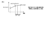
図5は断面手動決定モードの説明図である。断面手動決定モードの起動下では断面画像発生部115は一連のボリュームデータファイルから離散的に幾つかのボリュームデータファイルを対象としてXY面に平行な共通する断面候補を設定する。初期的な断面候補は、例えばXYZ座標系の原点を通るXY面設定される。対象とされるボリュームデータファイルとしては、例えば一連のボリュームデータファイルの両端と中央の3つのボリュームデータファイルが初期的に選択される。これら3つのボリュームデータファイルに対して同じ位置の初期的な候補断面に関する断面画像が断面画像発生部115により発生される。候補断面に関する3つの断面画像は表示部117に同時に又は択一的に表示される。操作者は図示しない入力デバイスを介して候補断面をZ軸に沿って移動させながら関心部位の像が最も好適に映る断面を探索し、その断面画像上に当該関心部位の例えばほぼ中心点(関心点又は指定点という)を指定する。3つのボリュームデータファイル全てに対して個々に断面を探索し、関心点を指定する。断面位置決定部125は、手動指定の対象とされる3つのボリュームデータファイル以外のそれらの間の他のボリュームデータファイルの関心点を、図6に示すように、時間軸上で当該補間対象のボリュームデータファイルを挟む2つのボリュームデータファイル上で指定した2つの指定点を使って線形補間により推定する。推定される関心点は2つの指定点を結ぶ3次元座標系での直線上であって、補間対象のボリュームデータファイルの時刻に対する手動指定されたボリュームデータファイルの時刻との間の時間幅Δt1、Δt2により線形補間により計算される点に決定される。推定した指定点の座標は後から手動で変更可能である。
FIG. 5 is an explanatory diagram of the manual section determination mode. Under the activation of the manual cross section determination mode, the cross
複数のボリュームデータファイルそれぞれ対して指定され又は補間された関心点を含み、かつXY面に平行な断面が、ボリュームデータファイルそれぞれ対して決定される。 A cross section that includes a point of interest designated or interpolated for each of the plurality of volume data files and that is parallel to the XY plane is determined for each of the volume data files.
断面画像発生部115により、設定された断面に従って複数のボリュームデータファイルにそれぞれ対応する複数の断面画像が生成される。複数の断面画像はボリュームデータファイル記憶部113に記憶される。ボリュームデータファイル記憶部113から表示部117への再生コントローラ118による読み出し制御により、上述した通り動画として順方向再生と逆方向再生とが交互に繰り返される。再生コントローラ118による読み出し制御又は表示部117内のフレームメモリに対する書き込み制御により、各断面画像上の関心点が表示部117のディスプレイ上の特定位置、典型的には中心位置に配置されるように断面画像の表示位置が個別にシフトされる。
The slice
図14、図15に例示するように、動画再生に際して常に関心部位を含む断面画像が表示され、しかも関心部位の像が画面の特定位置に固定される。それにより腫瘍の癒着などの診断に効果的である。 As illustrated in FIGS. 14 and 15, a cross-sectional image including a region of interest is always displayed during moving image reproduction, and the image of the region of interest is fixed at a specific position on the screen. This is effective for diagnosis such as tumor adhesion.
図7は第1の断面自動設定モードの説明図である。第1の断面自動設定モードの起動下では断面画像発生部115は一連のボリュームデータファイルから特定の単一のボリュームデータファイルを対象として例えばXY面に平行な原点を通る初期的な断面候補に関する断面画像を発生する。特定の単一のボリュームデータファイルとしては典型的には一連のボリュームデータファイルの中の中央時刻に最も近いボリュームデータファイルである。操作者は図示しない入力デバイスを介して候補断面をZ軸に沿って移動させながら関心部位の像が最も好適に映る断面を探索し、その断面画像上に当該関心部位内の点を指定する。
FIG. 7 is an explanatory diagram of the first automatic section setting mode. Under the activation of the first automatic section setting mode, the cross-section
断面位置決定部125は、指定された関心部位領域内の例えば中央ボクセル値又は平均ボクセル値を用いて、指定された関心部位領域を含む所定の大きさに制限された探索範囲内を対象として他のボリュームデータファイル各々から例えば閾値処理により関心部位領域を抽出する。断面位置決定部125は、抽出された関心部位領域各々の例えば重心を、各ボリュームデータファイルの関心点として設定する。
The cross-sectional
関心点が設定された以後の断面決定及び動画再生処理は上述した手動設定モードで説明した処理に等価である。つまり、複数のボリュームデータファイルそれぞれ対して設定された関心点を含み、かつXY面に平行な断面が、ボリュームデータファイルそれぞれ対して決定され、決定された断面に従って複数のボリュームデータファイルにそれぞれ対応する複数の断面画像が生成され、再生コントローラ118による読み出し制御のもとで順方向再生と逆方向再生とが交互に繰り返される。
The cross-section determination and moving image playback processing after the interest point is set is equivalent to the processing described in the manual setting mode described above. That is, a cross section that includes a point of interest set for each of the plurality of volume data files and is parallel to the XY plane is determined for each of the volume data files, and corresponds to each of the plurality of volume data files according to the determined cross section. A plurality of cross-sectional images are generated, and forward reproduction and reverse reproduction are alternately repeated under read control by the
この第1の断面自動設定モードは手動設定モードと同様に関心部位が腫瘍等の一塊形状であるときに好適である。 This first automatic section setting mode is suitable when the region of interest has a lump shape such as a tumor, as in the manual setting mode.
図8は第2の断面自動設定モードの説明図である。第2の断面自動設定モードは対象が気管支や血管等の管状部位であるときに好適である。断面位置決定部125により一連のボリュームデータファイル各々から閾値処理により例えば血管領域が抽出される。抽出された血管領域に対して図9に示すように狭窄等を含む関心区間が例えばその両端の2点を操作者が指定することにより設定される。断面位置決定部125により、指定された2点を通る、抽出された血管領域の血管芯線が特定される。指定された2点間の血管芯線を含むように、断面位置、XYZ各軸に対する断面のオブリーク角、さらに最小の断面厚が断面位置決定部125により複数のボリュームデータファイルそれぞれについて個々に決定される。操作者が1点指定の場合、主流の起始部へ向かって自動で芯線を特定できる。
FIG. 8 is an explanatory diagram of the second automatic section setting mode. The second automatic section setting mode is suitable when the target is a tubular part such as a bronchus or a blood vessel. For example, a blood vessel region is extracted from each of the series of volume data files by the cross-sectional
断面決定以後の断面画像発生処理及び動画再生処理は上述した手動設定モードで説明した処理に略等価である。本モードでは、断面に垂直な断面厚方向にボクセル値は加算されることにより断面画像が発生される。複数のボリュームデータファイルそれぞれ対して決定された断面に従って複数のボリュームデータファイルにそれぞれ対応する複数の断面画像が生成され、再生コントローラ118による読み出し制御のもとで順方向再生と逆方向再生とが交互に繰り返される。
The section image generation process and the moving image reproduction process after the section determination are substantially equivalent to the process described in the manual setting mode. In this mode, a cross-sectional image is generated by adding voxel values in the cross-sectional thickness direction perpendicular to the cross-section. A plurality of cross-sectional images respectively corresponding to the plurality of volume data files are generated according to the cross-section determined for each of the plurality of volume data files, and forward playback and reverse playback are alternately performed under read control by the
この第2の断面自動設定モードでは、心臓の冠状動脈などの複雑に屈曲した血管等の関心区間全体を常に画面上で視認することができる。 In the second automatic section setting mode, the entire section of interest such as a complexly bent blood vessel such as the coronary artery of the heart can be always visually confirmed on the screen.
図10は第3の断面自動設定モードの説明図である。第3の断面自動設定モードもその対象が気管支や血管等の管状部位であるときに好適である。断面位置決定部125により一連のボリュームデータファイル各々から閾値処理により例えば血管領域が抽出される。抽出された血管領域に対して図11に示すように狭窄等を含む関心区間がその両端の2点を操作者が指定することにより設定される。なお、血管の例えば末梢側の1点を操作者が指定し、血管上部まで自動的にトレースし、血管末梢と血管上部との間に関心区間を設定するようにしても良い。
FIG. 10 is an explanatory diagram of the third automatic section setting mode. The third automatic section setting mode is also suitable when the target is a tubular part such as a bronchus or a blood vessel. For example, a blood vessel region is extracted from each of the series of volume data files by the cross-sectional
断面位置決定部125により、指定された2点を通る、抽出された血管領域の血管芯線が特定される。指定された2点間の血管芯線のXY面への投影像に沿って、XY面に垂直な断面を、XY面に垂直な状態を維持したままで湾曲する。それにより複数のボリュームデータファイルそれぞれについて個々に断面(湾曲断面)決定される。
The cross-sectional
断面決定以後の断面画像発生処理及び動画再生処理は上述した手動設定モードで説明した処理に略等価である。複数のボリュームデータファイルそれぞれ対して決定された湾曲断面に従って複数のボリュームデータファイルにそれぞれ対応する複数の断面画像が生成され、再生コントローラ118による読み出し制御のもとで順方向再生と逆方向再生とが交互に繰り返される。
The section image generation process and the moving image reproduction process after the section determination are substantially equivalent to the process described in the manual setting mode. A plurality of cross-sectional images respectively corresponding to the plurality of volume data files are generated according to the curved cross-section determined for each of the plurality of volume data files, and forward playback and reverse playback are performed under the read control by the
この第3の断面自動設定モードでは、第2の断面自動設定モードのそれよりもより詳細な状態で複雑に屈曲した血管等の関心区間全体を常に画面上で視認することができる。 In the third automatic section setting mode, the entire section of interest such as a blood vessel bent in a complicated manner in a more detailed state than that in the second automatic section setting mode can always be visually confirmed on the screen.
なお、第2、第3の断面自動設定モードで発生される断面画像上で複雑に走行する血管の像が図12、図13に示すように直線的になるように断面画像発生部115により変形するようにしてもよい。
Note that the image of the blood vessel that travels in a complex manner on the cross-sectional images generated in the second and third automatic cross-section setting modes is deformed by the
なお、断面に限らず、仮想内視鏡モードも呼吸動等によって設定した視点が気管支外等へズレてしまうのを視点を設定することで可能とすることにも応用出来る。 In addition to the cross section, the virtual endoscope mode can also be applied to enable the viewpoint set by breathing motion or the like to be shifted outside the bronchus by setting the viewpoint.
移動軌跡作図処理部127は、断面位置決定部125で断面決定時に用いた関心部位に関する関心点と、それと同じ又は他の関心部位に関する他の関心点それぞれに関する3次元位置、つまりxyz座標を全呼吸位相にわたって特定する。他の関心点は、操作者による手動又は領域抽出処理を伴って半自動により全呼吸位相にわたる複数のボリュームデータファイルから特定される。例えば、複数の関心点が、腫瘍領域、大動脈領域、横隔膜領域、肋骨領域それぞれの領域重心、中心又は特定構造を示す位置に設定される。
The movement trajectory
移動軌跡作図処理部127は、全呼吸位相にわたって特定された複数の関心点にそれぞれ対応する3次元位置を用いて、関心点ごとに個々に呼吸運動に伴う移動軌跡を示す3次元マップと3種の2次元マップとを発生する(図16参照)。3次元マップはxyzの直交3軸座標系上に全呼吸位相にわたって全ての関心点をプロットすることにより生成される。関心点の表示態様、例えばカラーが関心部位毎に相違される。また関心点の移動方向が分かるように吸気から呼気に向かう方向を示す→等のマーカが関心点ごとに並記される。なお、表示部117への表示に際しては3次元マップは、操作者が自由に指定及び移動できる視点から平行投影処理により疑似3次元化される。
The movement trajectory
3種の2次元マップとして、xyの直交2軸座標系上に全呼吸位相にわたって全ての関心点をプロットすることにより生成されるアキシャルマップと、xzの直交2軸座標系上に全呼吸位相にわたって全ての関心点をプロットすることにより生成されるコロナルマップと、yzの直交2軸座標系上に全呼吸位相にわたって全ての関心点をプロットすることにより生成されるサジタルマップとが生成される。 Three types of two-dimensional maps, an axial map generated by plotting all points of interest over the entire respiratory phase on the xy orthogonal biaxial coordinate system, and the entire respiratory phase over the xz orthogonal biaxial coordinate system A coronal map generated by plotting all points of interest and a sagittal map generated by plotting all points of interest over the entire respiratory phase on a yz orthogonal biaxial coordinate system are generated.
表示に際しては、ホストコントローラ110の制御のもとで、3次元マップが3種の2次元マップ、又は操作者により任意に指定された1又は2つの2次元マップとともに同一画面に表示される。表示方法としては、3次元マップと2次元マップとが静止画として表示され、または呼吸位相の進行に従って表示点が移動する動画のように表示するようにしてもよい。 At the time of display, under the control of the host controller 110, the three-dimensional map is displayed on the same screen together with the three types of two-dimensional maps or one or two two-dimensional maps arbitrarily designated by the operator. As a display method, the three-dimensional map and the two-dimensional map may be displayed as still images, or may be displayed as a moving image in which the display point moves as the respiratory phase progresses.
複数の関心点の移動軌跡を表示することで、関心点間の移動の差異、例えば大動脈の移動量に対し腫瘍の移動量が大幅に大きいこと等を視覚的に把握することができる。 By displaying the movement trajectories of a plurality of points of interest, it is possible to visually grasp the difference in movement between the points of interest, for example, that the amount of movement of the tumor is significantly larger than the amount of movement of the aorta.
距離計測部129は、複数の位相にわたる関心点の移動距離を関心点毎に計測する。この距離は両端位置間の直線的な距離であっても良いし、移動経路に沿った実際に移動する距離であってもよい。各関心点の移動距離は図16に示すように3次元マップ及び2次元マップとともに表示される。
The
また距離計測部129は、3次元マップ又は2次元マップ上で操作者が任意に指定した2つの関心点間の距離を呼吸位相ごとに計測する。距離計測部129は、複数の呼吸位相のなかで最大距離、最小距離、変化率などの指標を特定又は計算し、図16に示すように3次元マップ及び2次元マップとともに表示する。また距離計測部129は、操作者により指定された特定位相の関心点間距離を図16に示すように3次元マップ及び2次元マップとともに表示する。
The
3以上の関心点を計算対象として指定したとき、距離計測部129は、3以上の関心点で包囲された領域の面積又は体積を呼吸位相ごとに計算する。距離計測部129は、複数の呼吸位相のなかで最大面積、最大体積、それらの変化率などの指標を計算し、3次元マップ及び2次元マップとともに表示する。
When three or more points of interest are designated as calculation targets, the
このように関心点の移動量を表示したり、面積や体積などから形状変化を表すことも出来る。さらに関心点の指定により、気管支の収縮度や拡張度、壁厚などの意義のある計測が可能である。もちろん呼吸動によって計測位置が異ならないように収縮・拡張に合わせて計測位置も追従して計測するものとする。 In this way, the movement amount of the point of interest can be displayed, and the shape change can be expressed from the area or volume. Furthermore, by specifying the points of interest, meaningful measurements such as bronchoconstriction and dilation and wall thickness can be made. Of course, the measurement position is also measured following the contraction / expansion so that the measurement position does not differ depending on the respiratory motion.
このように関心領域に対し呼吸位相毎の動きの位置や量を自動的に定量解析しグラフ化可能である。動きによる影響があっても関心領域を中心に表示することが可能となり,関心領域が呼吸動や拍動によって どのような影響があるかを確認し、さらに定量解析することが出来る。これら情報は放射線治療計画用に定量化した動きの量をデータ変換し、その計画に活用可能である。 Thus, the position and amount of movement for each respiratory phase can be automatically quantitatively analyzed and graphed with respect to the region of interest. Even if there is an influence of movement, it is possible to display the area of interest as the center, and it is possible to confirm what kind of influence the area of interest has due to respiratory motion or pulsation, and to further quantitatively analyze it. This information can be converted into data for the amount of movement quantified for radiation therapy planning and used for that planning.
本発明のいくつかの実施形態を説明したが、これらの実施形態は、例として提示したものであり、発明の範囲を限定することは意図していない。これら実施形態は、その他の様々な形態で実施されることが可能であり、発明の要旨を逸脱しない範囲で、種々の省略、置き換え、変更を行うことができる。これら実施形態やその変形は、発明の範囲や要旨に含まれると同様に、特許請求の範囲に記載された発明とその均等の範囲に含まれるものである。 Although several embodiments of the present invention have been described, these embodiments are presented by way of example and are not intended to limit the scope of the invention. These embodiments can be implemented in various other forms, and various omissions, replacements, and changes can be made without departing from the spirit of the invention. These embodiments and their modifications are included in the scope and gist of the invention, and are also included in the invention described in the claims and the equivalents thereof.
100…架台部、101…X線管、102…回転フレーム、103…2次元検出器、104…データ収集装置、106…前処理装置、107…架台駆動部、109…高電圧発生器、110…ホストコントローラ、112…投影データ記憶部、113…ボリュームデータファイル記憶部、115…断面画像発生部、116…コーンビーム再構成処理部、117…表示部(ディスプレイ)、118…再生コントローラ、120…呼吸センサ、121…呼吸波形記憶部、123…最大値/最小値特定部、125…断面位置決定部、127…移動軌跡作図処理部、129…距離計測部。
DESCRIPTION OF
Claims (8)
前記特定された関心点の3次元位置に基づいて、前記複数の位相にわたる前記関心点の移動距離を計測する距離計測部と、
前記特定された複数の3次元位置に基づいて、前記関心点にそれぞれ対応する前記生理的運動に伴う移動軌跡に関する3次元マップと2次元マップとを発生するマップ発生部と、
前記3次元マップと前記2次元マップとを表示する表示部と、
を具備することを特徴とする医用画像表示装置。 A position specifying unit that specifies a three-dimensional position of a point of interest for each phase using a plurality of volume data files related to a plurality of phases relating to a physiological motion of the subject;
A distance measuring unit that measures a moving distance of the point of interest across the plurality of phases based on a three-dimensional position of the identified point of interest ;
A map generating unit that generates a three-dimensional map and a two-dimensional map related to a movement trajectory associated with the physiological movement corresponding to each of the points of interest based on the plurality of specified three-dimensional positions;
A display unit for displaying the three-dimensional map and the two-dimensional map;
A medical image display device comprising:
前記距離計測部は前記特定された複数の3次元位置に基づいて前記複数の関心点間の距離を前記位相ごとに計測することを特徴とする請求項1記載の医用画像表示装置。 The position specifying unit specifies a plurality of three-dimensional positions related to a plurality of points of interest;
The medical image display apparatus according to claim 1, wherein the distance measurement unit measures distances between the plurality of points of interest for each phase based on the plurality of specified three-dimensional positions.
前記距離計測部は前記特定された3以上の3次元位置に基づいて前記3以上の関心点で包囲された領域の面積又は体積を前記位相ごとに計算することを特徴とする請求項1記載の医用画像表示装置。 The position specifying unit specifies three or more three-dimensional positions related to three or more points of interest;
Claim 1 wherein the distance measuring unit, characterized in that to calculate the area or volume of the surrounding area in the three or more interest point based on the three-dimensional positions of three or more, which is the specified prior to each SL-position phase The medical image display device described.
Priority Applications (1)
| Application Number | Priority Date | Filing Date | Title |
|---|---|---|---|
| JP2010237804A JP5777317B2 (en) | 2010-10-22 | 2010-10-22 | Medical image display device |
Applications Claiming Priority (1)
| Application Number | Priority Date | Filing Date | Title |
|---|---|---|---|
| JP2010237804A JP5777317B2 (en) | 2010-10-22 | 2010-10-22 | Medical image display device |
Publications (2)
| Publication Number | Publication Date |
|---|---|
| JP2012085969A JP2012085969A (en) | 2012-05-10 |
| JP5777317B2 true JP5777317B2 (en) | 2015-09-09 |
Family
ID=46258246
Family Applications (1)
| Application Number | Title | Priority Date | Filing Date |
|---|---|---|---|
| JP2010237804A Active JP5777317B2 (en) | 2010-10-22 | 2010-10-22 | Medical image display device |
Country Status (1)
| Country | Link |
|---|---|
| JP (1) | JP5777317B2 (en) |
Cited By (1)
| Publication number | Priority date | Publication date | Assignee | Title |
|---|---|---|---|---|
| WO2023139252A1 (en) * | 2022-01-24 | 2023-07-27 | Karl Storz Se & Co. Kg | Method and measuring device for correcting a position of a measurement point |
Families Citing this family (5)
| Publication number | Priority date | Publication date | Assignee | Title |
|---|---|---|---|---|
| JP6207936B2 (en) | 2012-09-03 | 2017-10-04 | 東芝メディカルシステムズ株式会社 | Medical image processing apparatus and radiotherapy apparatus |
| JP2014144156A (en) * | 2013-01-30 | 2014-08-14 | Fujifilm Corp | Medical image display control device and method, and program |
| JP6716197B2 (en) * | 2014-02-28 | 2020-07-01 | キヤノンメディカルシステムズ株式会社 | Image processing apparatus and X-ray diagnostic apparatus |
| JP6407569B2 (en) * | 2014-06-02 | 2018-10-17 | キヤノンメディカルシステムズ株式会社 | Medical image processing apparatus and medical image processing method |
| JP6755468B2 (en) * | 2015-04-27 | 2020-09-16 | 国立研究開発法人国立がん研究センター | Medical image processing device |
Family Cites Families (4)
| Publication number | Priority date | Publication date | Assignee | Title |
|---|---|---|---|---|
| JP3325635B2 (en) * | 1993-03-19 | 2002-09-17 | 株式会社日立メディコ | Image processing method and apparatus |
| US8005284B2 (en) * | 2006-12-07 | 2011-08-23 | Kabushiki Kaisha Toshiba | Three dimensional image processing apparatus and x-ray diagnosis apparatus |
| JP2009045251A (en) * | 2007-08-21 | 2009-03-05 | Toshiba Corp | Treatment support equipment |
| JP2010069099A (en) * | 2008-09-19 | 2010-04-02 | Toshiba Corp | Image processing apparatus and x-ray computed tomography apparatus |
-
2010
- 2010-10-22 JP JP2010237804A patent/JP5777317B2/en active Active
Cited By (1)
| Publication number | Priority date | Publication date | Assignee | Title |
|---|---|---|---|---|
| WO2023139252A1 (en) * | 2022-01-24 | 2023-07-27 | Karl Storz Se & Co. Kg | Method and measuring device for correcting a position of a measurement point |
Also Published As
| Publication number | Publication date |
|---|---|
| JP2012085969A (en) | 2012-05-10 |
Similar Documents
| Publication | Publication Date | Title |
|---|---|---|
| US8798227B2 (en) | Medical image processing apparatus and X-ray computed tomography apparatus | |
| JP5897273B2 (en) | Medical image display apparatus and X-ray computed tomography apparatus | |
| US20210128011A1 (en) | Method and System for 4D Radiological Intervention Guidance (4D-cath) | |
| US20180070855A1 (en) | System and method for determining the position of the tip of a medical catheter within the body of a patient | |
| CN103179916B (en) | The self adaptive imaging of the real-time geometric sensing based on medicine equipment and frame per second optimization | |
| JP4346297B2 (en) | X-ray computed tomography apparatus, image processing apparatus, and image processing method | |
| JP5681342B2 (en) | System for tracking the respiratory cycle of a subject | |
| JP5777317B2 (en) | Medical image display device | |
| US20120250966A1 (en) | X-ray ct apparatus and image processing method | |
| JPWO2005089651A1 (en) | Image data collection control method and image data collection apparatus | |
| JP2011161220A (en) | Image processing apparatus, x-ray computed tomography apparatus, and image processing program | |
| CN101902967B (en) | Correction for un-voluntary respiratory motion in cardiac CT | |
| WO2012046846A1 (en) | Image processing device for medical use | |
| JP2010512915A (en) | Imaging system and imaging method for imaging an object | |
| TW201919544A (en) | Systems and methods for ultra low dose CT fluoroscopy | |
| CN102427767B (en) | The data acquisition and visualization formulation that guide is got involved for low dosage in computer tomography | |
| JP5743445B2 (en) | Radiation computed tomography apparatus, medical image generation apparatus, and respiratory phase measurement apparatus | |
| JP4334037B2 (en) | Medical image processing device | |
| US20100266182A1 (en) | Apparatus for determining a parameter of a moving object | |
| JP5984237B2 (en) | Medical image processing apparatus and X-ray computed tomography apparatus | |
| JP2008067991A (en) | Image diagnosing system, data display device for matter inside of lumen and data display method for matter inside of lumen | |
| JP4745029B2 (en) | X-ray CT system | |
| US7646844B2 (en) | Method for operating a medical examination apparatus and an examination apparatus associated therewith | |
| CN109152561A (en) | The acquisition adjusted through anatomical structure is carried out using fixed multi-source x-ray system | |
| CN115702826A (en) | Method and system for guiding device insertion during medical imaging |
Legal Events
| Date | Code | Title | Description |
|---|---|---|---|
| A621 | Written request for application examination |
Free format text: JAPANESE INTERMEDIATE CODE: A621 Effective date: 20131008 |
|
| RD04 | Notification of resignation of power of attorney |
Free format text: JAPANESE INTERMEDIATE CODE: A7424 Effective date: 20131205 |
|
| RD04 | Notification of resignation of power of attorney |
Free format text: JAPANESE INTERMEDIATE CODE: A7424 Effective date: 20131212 |
|
| RD04 | Notification of resignation of power of attorney |
Free format text: JAPANESE INTERMEDIATE CODE: A7424 Effective date: 20131219 |
|
| RD04 | Notification of resignation of power of attorney |
Free format text: JAPANESE INTERMEDIATE CODE: A7424 Effective date: 20131226 |
|
| RD04 | Notification of resignation of power of attorney |
Free format text: JAPANESE INTERMEDIATE CODE: A7424 Effective date: 20140109 |
|
| RD04 | Notification of resignation of power of attorney |
Free format text: JAPANESE INTERMEDIATE CODE: A7424 Effective date: 20140116 |
|
| A977 | Report on retrieval |
Free format text: JAPANESE INTERMEDIATE CODE: A971007 Effective date: 20140328 |
|
| A131 | Notification of reasons for refusal |
Free format text: JAPANESE INTERMEDIATE CODE: A131 Effective date: 20140408 |
|
| A521 | Request for written amendment filed |
Free format text: JAPANESE INTERMEDIATE CODE: A523 Effective date: 20140606 |
|
| A131 | Notification of reasons for refusal |
Free format text: JAPANESE INTERMEDIATE CODE: A131 Effective date: 20141028 |
|
| A521 | Request for written amendment filed |
Free format text: JAPANESE INTERMEDIATE CODE: A523 Effective date: 20150105 |
|
| TRDD | Decision of grant or rejection written | ||
| A01 | Written decision to grant a patent or to grant a registration (utility model) |
Free format text: JAPANESE INTERMEDIATE CODE: A01 Effective date: 20150609 |
|
| A61 | First payment of annual fees (during grant procedure) |
Free format text: JAPANESE INTERMEDIATE CODE: A61 Effective date: 20150707 |
|
| R150 | Certificate of patent or registration of utility model |
Ref document number: 5777317 Country of ref document: JP Free format text: JAPANESE INTERMEDIATE CODE: R150 |
|
| S111 | Request for change of ownership or part of ownership |
Free format text: JAPANESE INTERMEDIATE CODE: R313117 |
|
| R350 | Written notification of registration of transfer |
Free format text: JAPANESE INTERMEDIATE CODE: R350 |
|
| S533 | Written request for registration of change of name |
Free format text: JAPANESE INTERMEDIATE CODE: R313533 |
|
| R350 | Written notification of registration of transfer |
Free format text: JAPANESE INTERMEDIATE CODE: R350 |