JP5743445B2 - Radiation computed tomography apparatus, medical image generation apparatus, and respiratory phase measurement apparatus - Google Patents
Radiation computed tomography apparatus, medical image generation apparatus, and respiratory phase measurement apparatus Download PDFInfo
- Publication number
- JP5743445B2 JP5743445B2 JP2010159048A JP2010159048A JP5743445B2 JP 5743445 B2 JP5743445 B2 JP 5743445B2 JP 2010159048 A JP2010159048 A JP 2010159048A JP 2010159048 A JP2010159048 A JP 2010159048A JP 5743445 B2 JP5743445 B2 JP 5743445B2
- Authority
- JP
- Japan
- Prior art keywords
- value
- respiratory
- unit
- peak
- computed tomography
- Prior art date
- Legal status (The legal status is an assumption and is not a legal conclusion. Google has not performed a legal analysis and makes no representation as to the accuracy of the status listed.)
- Active
Links
- 230000000241 respiratory effect Effects 0.000 title claims description 78
- 238000002591 computed tomography Methods 0.000 title claims description 23
- 230000005855 radiation Effects 0.000 title claims description 21
- 238000005259 measurement Methods 0.000 title claims description 7
- 230000029058 respiratory gaseous exchange Effects 0.000 claims description 73
- 230000033001 locomotion Effects 0.000 claims description 13
- 238000013480 data collection Methods 0.000 claims description 11
- 238000013075 data extraction Methods 0.000 claims description 4
- 238000002604 ultrasonography Methods 0.000 claims 1
- 238000012545 processing Methods 0.000 description 13
- 238000003384 imaging method Methods 0.000 description 10
- 238000000034 method Methods 0.000 description 8
- 210000001015 abdomen Anatomy 0.000 description 7
- 238000007781 pre-processing Methods 0.000 description 7
- 230000035945 sensitivity Effects 0.000 description 6
- 238000013500 data storage Methods 0.000 description 4
- 238000000605 extraction Methods 0.000 description 4
- 230000003187 abdominal effect Effects 0.000 description 3
- 230000001360 synchronised effect Effects 0.000 description 3
- 230000005540 biological transmission Effects 0.000 description 2
- 238000007796 conventional method Methods 0.000 description 2
- 230000007423 decrease Effects 0.000 description 2
- 238000006073 displacement reaction Methods 0.000 description 2
- 210000004072 lung Anatomy 0.000 description 2
- 238000002595 magnetic resonance imaging Methods 0.000 description 2
- 239000000463 material Substances 0.000 description 2
- 238000012805 post-processing Methods 0.000 description 2
- 230000002123 temporal effect Effects 0.000 description 2
- 206010028980 Neoplasm Diseases 0.000 description 1
- 239000006096 absorbing agent Substances 0.000 description 1
- 230000008602 contraction Effects 0.000 description 1
- 238000001514 detection method Methods 0.000 description 1
- 238000010586 diagram Methods 0.000 description 1
- 239000000284 extract Substances 0.000 description 1
- 230000003434 inspiratory effect Effects 0.000 description 1
- 230000010354 integration Effects 0.000 description 1
- 239000002184 metal Substances 0.000 description 1
- 238000012986 modification Methods 0.000 description 1
- 230000004048 modification Effects 0.000 description 1
- 230000003287 optical effect Effects 0.000 description 1
- 230000000737 periodic effect Effects 0.000 description 1
- 238000002360 preparation method Methods 0.000 description 1
Images


Landscapes
- Measurement Of The Respiration, Hearing Ability, Form, And Blood Characteristics Of Living Organisms (AREA)
- Apparatus For Radiation Diagnosis (AREA)
- Magnetic Resonance Imaging Apparatus (AREA)
- Ultra Sonic Daignosis Equipment (AREA)
Description
本発明の実施形態は、放射線コンピュータ断層撮影装置、医用画像発生装置及び呼吸位相計測装置に関する。 Embodiments described herein relate generally to a radiation computed tomography apparatus, a medical image generation apparatus, and a respiratory phase measurement apparatus.
ある放射線コンピュータ断層撮影装置(CT)は、呼吸に同期した投影データを収集し、また呼吸に同期した画像を生成するために、呼吸センサを装備する。呼吸センサは、例えば吸気のピークでトリガ信号を出力する。呼吸同期ヘリカルスキャンでは、トリガ信号から特定した呼吸周期に応じてヘリカルピッチが決定される。呼吸同期再構成では、隣り合うトリガ信号の期間を100等分して、各時刻に0%〜100%の呼吸位相を割り当てる。任意の呼吸位相が指定され、その指定された呼吸位相を中心とした期間に収集された投影データから3次元画像が再構成される。複数、例えば10位相を指定した場合、4次元画像を得ることができる。3次元に加えて、呼吸位相という次元を加えて4次元画像を得る。 Some radiation computed tomography (CT) devices are equipped with a respiration sensor to collect projection data synchronized to respiration and to generate images synchronized to respiration. For example, the respiration sensor outputs a trigger signal at the peak of inspiration. In the respiratory-synchronized helical scan, the helical pitch is determined according to the respiratory cycle specified from the trigger signal. In respiratory synchronization reconstruction, the periods of adjacent trigger signals are equally divided into 100, and a respiratory phase of 0% to 100% is assigned to each time. An arbitrary respiration phase is designated, and a three-dimensional image is reconstructed from projection data collected during a period centered on the designated respiration phase. When a plurality of, for example, 10 phases are designated, a four-dimensional image can be obtained. In addition to three dimensions, a dimension called respiratory phase is added to obtain a four-dimensional image.
呼吸は、呼吸する毎にその深さが異なる。特に吸気のレベルはばらつきが大きい。トリガの出力された位相(0%)で再構成したとしても、呼吸の深さが異なるため、再構成された画像は、不連続部が生じる。この不連続部は位相が0%でなくとも起こる。呼吸の深さが同じでない限り、この不連続部は避けられないという問題点がある。 The depth of breathing varies with each breath. In particular, the intake air level varies greatly. Even if reconstruction is performed at the output phase (0%) of the trigger, the reconstructed image has discontinuities due to different breathing depths. This discontinuity occurs even if the phase is not 0%. This discontinuity is inevitable unless the breathing depth is the same.
目的は、呼吸動作と呼吸位相とのズレを軽減することにある。 The purpose is to reduce the difference between the breathing motion and the breathing phase.
本実施形態に係る放射線コンピュータ断層撮影装置は、被検体に関する投影データを収集するデータ収集部を有する。データ抽出部は、被検体の呼吸動作を計測した複数の呼吸周期にわたる呼吸波形における複数のピーク値の内の一つの値と複数のボトム値の内の一つの値との範囲に従って、画像再構成に要する角度範囲に対応する投影データセットを投影データから抽出する。再構成部は、抽出された投影データセットに基づいて画像データを再構成する。表示部は画像データを表示する。
The radiation computed tomography apparatus according to this embodiment includes a data collection unit that collects projection data related to a subject . Data extraction unit in accordance with the scope of one of the values of the single values and the plurality of bottom value of the plurality of peak value in the respiratory waveform over a plurality of respiratory cycles measured the respiration of the subject, A projection data set corresponding to the angle range required for image reconstruction is extracted from the projection data. The reconstruction unit reconstructs image data based on the extracted projection data set. The display unit displays image data.
以下、図面を参照しながら本実施形態に係わる放射線コンピュータ断層撮影装置、医用画像発生装置及び呼吸位相計測装置を説明する。医用画像発生装置は、被検体に関するデータを放射線、超音波又は高周波磁場を用いて収集し、この収集したデータに基づいて医用画像のデータを発生する。医用画像発生装置には、放射線コンピュータ断層撮影装置(CTスキャナ)、超音波診断装置、磁気共鳴映像装置(MRI)が含まれる。放射線コンピュータ断層撮影装置として以下説明する。 Hereinafter, a radiation computed tomography apparatus, a medical image generation apparatus, and a respiratory phase measurement apparatus according to the present embodiment will be described with reference to the drawings. The medical image generation apparatus collects data relating to a subject using radiation, ultrasonic waves, or a high-frequency magnetic field, and generates medical image data based on the collected data. Medical image generation apparatuses include a radiation computed tomography apparatus (CT scanner), an ultrasonic diagnostic apparatus, and a magnetic resonance imaging apparatus (MRI). A radiation computed tomography apparatus will be described below.
図1に、本実施形態に係る放射線コンピュータ断層撮影装置の構成をブロック図により示している。図2には図1の架台の内部を示している。架台部100は、Z軸を中心として回転自在に支持される回転フレーム102を有する。回転フレーム102は架台駆動部107により駆動され、回転する。回転フレーム102にはコーンビーム形X線管101と2次元検出器103とが、Z軸を中心とした撮影領域Sを挟んで対向して搭載される。撮影領域Sには図示しないが寝台の天板に載置された被検体が配置される。天板はZ軸方向に任意の速度で移動可能に設けられる。X線管101は、高電圧発生器109から高電圧の印加を受けて、X線を四角錐形に放射する。2次元検出器103は、同時に複数スライス分の投影データを検出できるようにX線焦点Fを中心として円弧状に複数のX線検出素子が配列され、さらにこのX線検出素子列がZ軸方向に複数並列される。
FIG. 1 is a block diagram showing the configuration of a radiation computed tomography apparatus according to this embodiment. FIG. 2 shows the inside of the gantry of FIG. The
2次元検出器103には一般的にDAS(data acquisition system) と呼ばれているデータ収集装置104が接続されている。データ収集装置104には、2次元検出器103の各チャンネルの電流信号を電圧に変換するI−V変換器と、この電圧信号をX線の曝射周期に同期して周期的に積分する積分器と、この積分器の出力信号を増幅するアンプと、このプリアンプの出力信号をディジタル信号に変換するアナログ・ディジタル・コンバータとが、チャンネルごとに設けられている。
The two-
データ収集装置104には光学的又は磁気的要素を媒介させる非接触データ伝送装置105を介して前処理装置106が接続される。前処理装置106は、データ収集装置104で検出されたデータに対して、チャンネル間の感度不均一を補正し、またX線強吸収体、主に金属部による極端な信号強度の低下又は信号脱落を補正する等の前処理を実行する。前処理装置106で前処理を受けたデータ(投影データ)は投影データ記憶部112に記憶される。投影データには、データ収集時刻に対応するタイムコード、チャンネル番号コード、ビュー角コード、回転回数コード、天板位置コードなどのデータ収集に係る位置及びタイミングに関する属性情報がホストコントローラ110の制御のもとで関連付けられる。
A
投影データセット抽出部119は、操作者が入力装置115を介して入力した所望の心拍位相に対応する投影データセットを、投影データ記憶部112に記憶された投影データから抽出する。投影データセットは、1枚又は1ボリュームの断層画像のデータを再構成するのに要する投影データの1単位である。ヘリカルスキャンでは、補間処理を要するので、典型的には720°分の投影データから投影データセットが構成される。ヘリカルスキャン以外の通常のスキャンでは、360°分の投影データ、ハーフ再構成では180°+ファン角分の投影データから投影データセットが構成される。表示装置116は、再構成された断層画像を表示するために設けられる。
The projection data
スキャン条件/再構成条件設定支援処理部117は、操作者がスキャン条件/再構成条件を設定する作業を支援するためのスキャン条件/再構成条件の設定画面を生成する。スキャン条件/再構成条件の設定画面は、図14、図15に例示されており、詳細は後述する。
The scan condition / reconstruction condition setting
ホストコントローラ110は、スキャン条件/再構成条件設定支援処理部117の支援のもとで設定されたスキャン条件にしたがってスキャンを実行するように架台駆動部107、高電圧発生装置109、データ収集回路104、前処理部106等を制御する。ホストコントローラ110は、スキャン条件/再構成条件設定支援処理部117の支援のもとで設定された再構成条件にしたがって断層画像を再構成するように投影データセット抽出部117、再構成処理部118等を制御する。
The
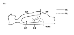
上記スキャン及び再構成処理は、特定のスキャン条件、特定の再構成条件のもとでは、呼吸位相に同期した処理がなされる。被検体の呼吸位相を計測するために呼吸位相計測装置が設けられる。呼吸位相計測装置は、呼吸センサ120を有する。呼吸センサ120は、図3、図5に示す被検体の呼吸動作を測定する機能を有する。周知の通り、呼吸動作は、横隔膜の往復運動に伴なう肺野の拡張収縮である。肺野の拡張収縮に伴って腹部が前後に往復移動をする。図4に示すように、呼吸センサ120は、例えば腹部の往復移動を検出するために、天板などに設置された多関節アーム130に支持されるレーザ測長器128と、レーザ測長器128はレーザ発生器と受光器とからなる。レーザ測長器128が被検体の腹部が往復移動する方向と略平行にレーザを照射する位置及び向きになるよう多関節アーム130の各関節の角度は操作者により調整される。レーザ制御部129はレーザ測長器128のレーザ発生器と受光器とを動作させるとともに、被検体の腹部表面からの反射光の信号を処理してレーザ照射から反射光受光までの時間又は反射光信号の位相変化に基づいてレーザ発生器と被検体の腹部表面との間の距離をリアルタイムでまた繰り返し演算する。
The scanning and reconstruction processing is performed in synchronization with the respiratory phase under specific scanning conditions and specific reconstruction conditions. A respiratory phase measuring device is provided for measuring the respiratory phase of the subject. The respiratory phase measuring device has a
なお、この呼吸センサ120は、腹部にバンド状のものを巻き、バンドと腹部の間に圧力センサーを取り付け、圧力の変化により、呼吸の状態を観測するものでもよい。また、腹部上に載せた光反射材を取り付けたものを、カメラで撮影し、光反射材の部分の動きにより、呼吸の状態を観測するものでもよい。ここでは、上記以外のどのようなものであっても呼吸の吸気と呼気の状態を観測するものであればよい。
The
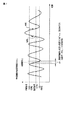
呼吸波形記憶部121は、レーザ制御部129から繰り返し出力されるレーザ発生器と被検体の腹部表面との間の距離を波高値として表している信号のデータ(波高値データ)をタイムコードとともに繰り返し記憶する。この波高値の時間変化は、被検体の呼吸の周期的な動作を反映している。計測期間中の波高値データセットを、以下、単に呼吸波形データと称する。図5、図6には呼吸波形を例示している。当該距離は、図6に示すように吸気では波高値が高くなり、呼気では波高値が低くなるものとして表しているが、呼吸と波高値との関係はそれに限定されない。ここでは吸気では波高値が高くなり、呼気では波高値が低くなるものとして説明する。また呼吸波形としては、距離の絶対値の変化ではなく、例えば測定開始時の距離を基準として当該基準距離からの変位の時間的変動であってもよい。
The respiration
図6に示すように、最大値/最小値選択部125は、呼吸波形から特定した複数のピークからその最小値を選択し、呼吸波形から特定した複数のボトムからその最大値を選択する。呼吸位相決定部127は、ボトムの最大値からピークの最小値までの範囲を百等分した波高値各々に対して、0%から100%までの各呼吸位相を対応付ける。
As shown in FIG. 6, the maximum value / minimum
以下、本実施形態の動作を説明する。本実施形態の動作としては、スキャン終了後に所望の呼吸位相を指定するポスト処理と、呼吸同期のもとでスキャンを実行するリアルタイム処理との大別される。まず、ポスト処理について説明する。 The operation of this embodiment will be described below. The operation of this embodiment is broadly divided into post processing for designating a desired respiratory phase after the end of scanning and real time processing for executing scanning under respiratory synchronization. First, post processing will be described.
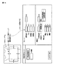
図14には、スキャン条件/再構成条件設定支援処理部117により生成され、表示装置116に表示されるスキャン条件/再構成条件設定画面を例示している。事前に撮影されたスキャノグラムが、撮影範囲(投影データ収集範囲)を表す四角の枠とともに表示される。操作者は入力装置115を操作して四角の枠のいずれかの辺や頂点をマウスでドラッグした状態で拡大、縮小、移動可能である。ここで示したZ軸方向の範囲、つまり体軸方向の撮影範囲は、画面右下のスキャンの撮影範囲に、自動的に数値で表示される。逆に撮影範囲を数値で入力することで、スキャノグラム上の四角の枠の位置が動く。また、X方向の範囲、つまり被検体の左右方向の撮影範囲は、X線のファン角に依存しており、右下のスキャンウインドウのFOV(Field of View)に自動的に数値で表示される。同じくFOVを数値入力することで、スキャノグラム上の四角の枠の位置が動く。管電圧、管電流はCTスキャンでの一般入力項目である。更にその下(右下)は、再構成条件の設定ウインドウが表示される。再構成範囲、再構成モード、呼吸位相が再構成条件として入力可能である。
FIG. 14 illustrates a scan condition / reconstruction condition setting screen generated by the scan condition / reconstruction condition setting
スキャン前に被検体の平均又は最大の呼吸周期を得るために、呼吸周期取得ボタンが画面中央左側に配置される。このボタンをクリックすることで、ホストコントローラ110は呼吸センサ120、呼吸波形記憶部121等を制御して、スキャン前に例えば5呼吸分の平均又は最大の呼吸周期を得て、これを表示する。
In order to obtain the average or maximum breathing cycle of the subject before scanning, a breathing cycle acquisition button is arranged on the left side of the center of the screen. By clicking this button, the
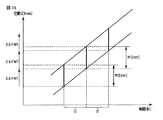
例えばヘリカルスキャンモードでは、平均又は最大の呼吸周期に従って図9に示すヘリカルピッチがスキャン条件/再構成条件設定支援処理部117により決められる。ヘリカルピッチは一般的には例えば図9に示すようにX線管101が1回転する時間(t1sec)に天板が移動する距離(V・t1、Vmmは天板の秒速)、または1回転する時間(t1秒)に、検出器103のZ軸方向に関する感度幅のX線コーン角に応じたZ軸上の相対距離(W1mm、図17参照)に対して天板が移動する比率(ピッチファクタPF)として定義される。ピッチファクタPFは、1回転する時間(t1秒)に天板が移動する距離が、検出器103のZ軸方向に関する感度幅のX線コーン角に応じたZ軸上の相対距離(W1mm)より小さくなるように設定される。典型的には、呼吸周期の間に天板が移動する距離が、検出器103のZ軸方向の感度幅の0.8倍となるようにピッチファクタPFが決定される(図16参照)。1呼吸周期をt2sec(t2>t1)とすると、天板移動速度Vは、例えば次のように示すことができる。
For example, in the helical scan mode, the helical pitch shown in FIG. 9 is determined by the scan condition / reconstruction condition setting
V[mm/s]=(0.8×W1[mm])/t2[s] (1)
上記の通りピッチファクタPFは1回転する時間(t1秒)に、W1に対して天板が移動する比率として定義されるので、
PF=(V[mm/s]×t1[s])/W1[mm] (2)
よって、(1)式を(2)式に単純に代入すると、
PF=( 0.8×W1[mm] ×t1[s])/(t2[s]×W1[mm])
=0.8× (t1[s])/(t2[s])
つまり、ピッチファクタPFは架台の回転速度と、呼吸周期により求まる。この回転速度と呼吸速度の比は、呼吸周期に対する時間分解能といえる。
V [mm / s] = (0.8 x W1 [mm]) / t2 [s] (1)
As described above, the pitch factor PF is defined as the ratio of the top plate moving with respect to W1 during one rotation time (t1 seconds).
PF = (V [mm / s] × t1 [s]) / W1 [mm] (2)
Therefore, if equation (1) is simply substituted into equation (2),
PF = (0.8 × W1 [mm] × t1 [s]) / (t2 [s] × W1 [mm])
= 0.8 x (t1 [s]) / (t2 [s])
That is, the pitch factor PF is obtained from the rotation speed of the gantry and the respiratory cycle. The ratio between the rotation speed and the respiration rate can be said to be a time resolution with respect to the respiration cycle.
この回転速度と呼吸速度の比を、例えば、高時間分可能モードでは15、低時間分解能モードでは最大10として、ユーザがこの撮影モードを任意に選択することができる。または、例えばこの比は予め10というように、システム中に設定しておくことで、システムが得られた呼吸周期から最も適した架台の回転速度を求める方法としてもよい。 For example, the ratio of the rotation speed and the respiration rate is set to 15 in the high time possible mode and 10 in the low time resolution mode, and the user can arbitrarily select the imaging mode. Alternatively, for example, this ratio may be set in the system in advance as 10 so that the most suitable rotation speed of the gantry is obtained from the respiratory cycle obtained by the system.
ここまでの設定操作が完了すると、スキャン実行ボタンがクリック可能とされる。スキャン実行ボタンのクリックにより、ホストコントローラ110の制御のもとでスキャンの準備が開始され、キーボードについているハードスイッチである曝射ボタンが点灯後、曝射ボタンを押すことでX線の照射をともなってスキャンが実際に開始される。
When the setting operations so far are completed, the scan execution button can be clicked. When the scan execution button is clicked, scanning preparation is started under the control of the
例えば指定された撮影範囲を上述の通り呼吸周期に応じたヘリカルピッチでヘリカルスキャンが実行される。ヘリカルスキャンに代えて、天板位置が固定した状態で連続的にスキャンが繰り返されるいわゆるダイナミックスキャンであってもよい。スキャン期間中、収集された投影データは投影データ記憶部112に記憶される。それとともに、呼吸センサ120で繰り返し測定された腹部表面の距離変化を反映した経時的な波高値データ、つまり呼吸波形データが呼吸波形記憶部121に記憶される。
For example, the helical scan is executed in the designated imaging range at the helical pitch corresponding to the respiratory cycle as described above. Instead of the helical scan, a so-called dynamic scan in which the scan is continuously repeated with the top plate position fixed may be used. During the scanning period, the collected projection data is stored in the projection
スキャン完了後、またはスキャン前に事前に、画像再構成に対応する所望の呼吸位相が指定される。図7、図15に示すように、記憶された呼吸波形が表示装置116に表示される。表示された呼吸波形には、所望の呼吸位相を指定するためのカーソルが重ねられる。カーソルの移動及び確定処理により所望の呼吸位相が指定される。指定された所望の呼吸位相に対応する波高値が特定される。
A desired respiratory phase corresponding to image reconstruction is specified after the scan is complete or prior to the scan. As shown in FIGS. 7 and 15, the stored respiratory waveform is displayed on the
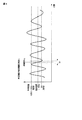
なお、呼吸位相決定部127は、吸気と呼気を区別して、吸気から呼気への変化期間(呼気期間)には−100%から0%を割り当て、呼気から吸気への変化期間(吸気期間)には0%から+100%を割り当てるようにしても良い。この場合、図8に示すように、所望の呼吸位相は、呼気期間と吸気期間とを区別して指定される。通常、呼吸に伴って関心部位、例えば腫瘍は往復移動を繰り返すが、その移動経路は往路と復路とで相違する。従って呼気期間と吸気期間とを区別することは有効である。
The respiratory
呼吸位相の割り当て設定条件、例えば開始位相、終了位相、位相間隔の初期設定は任意である。例えば、開始0%、終了100%、間隔10%と入力されれば、0、10、20、30、40、50、60、70、80、90、100%の呼吸位相が割り当てられ、それらの呼吸位相から指定された呼吸位相に対応する画像が再構成される。吸気と呼気を分けて、−100%、−80、−60、−40、−20、0、20、40、60又は80%の所望の呼吸位相が指定されると、指定された呼吸位相に対応する波高値を示す時刻を中心として投影データセットが抽出され、所望の呼吸位相に対応する断層画像が再構成されることとなる。ヘリカルスキャンでは、補間処理を要するので、典型的には720°分の投影データから投影データセットが構成される。 The respiratory phase assignment setting conditions, for example, the initial setting of the start phase, end phase, and phase interval are arbitrary. For example, if 0% start, 100% end, and 10% interval are entered, 0, 10, 20, 30, 40, 50, 60, 70, 80, 90, 100% respiratory phases are assigned, and An image corresponding to the specified respiratory phase is reconstructed from the respiratory phase. When inspiration and expiration are separated and a desired respiratory phase of −100%, −80, −60, −40, −20, 0, 20, 40, 60, or 80% is specified, the specified respiratory phase is set. A projection data set is extracted around the time indicating the corresponding peak value, and a tomographic image corresponding to a desired respiratory phase is reconstructed. Since helical scanning requires interpolation processing, a projection data set is typically composed of 720 ° projection data.
このように本実施形態では、所望の呼吸位相は、それに対応する波高値として指定される。この波高値による指定方法は、従来の所望の呼吸位相の指定方法である時間位相指定とは明確に区別される。従来の所望の呼吸位相の指定方法では、波高値ピークから次の呼吸周期の波高値ピークまでの期間を百等分して、それぞれに0%から+100%の呼吸位相を割り当てる。そして所望の呼吸位相に対応する時刻を中心として投影データセットが抽出され、抽出された投影データセットから断層画像が再構成される。 Thus, in the present embodiment, the desired respiratory phase is specified as the peak value corresponding thereto. This designation method based on the peak value is clearly distinguished from the time phase designation which is a conventional method for designating a desired respiratory phase. In the conventional method for specifying a desired breathing phase, the period from the peak value peak to the peak value peak of the next breathing cycle is divided equally, and a breathing phase of 0% to + 100% is assigned to each. Then, a projection data set is extracted around the time corresponding to the desired respiratory phase, and a tomographic image is reconstructed from the extracted projection data set.
それに対して本実施形態による波高値指定方法では、図7に示すように、呼吸位相が呼吸波形上のボトムの最大値とピークの最小値との間に割り当てられ、所望の呼吸位相に対応する波高値に一致した時刻を中心として、画像再構成に必要な角度分の投影データセットが抽出され、抽出された投影データセットから断層画像が再構成される。 On the other hand, in the peak value specifying method according to the present embodiment, as shown in FIG. 7, the respiratory phase is assigned between the maximum value of the bottom and the minimum value of the peak on the respiratory waveform, and corresponds to the desired respiratory phase. A projection data set for an angle necessary for image reconstruction is extracted around the time corresponding to the peak value, and a tomographic image is reconstructed from the extracted projection data set.
なお、図15に示すように、本実施形態では再構成モードを従来の時間位相指定方法と波高値指定方法とから選択的に指定することができるようになっている。下半分に呼吸波形が示され、ここに前記で自動設定された0%と100%が示される。この0%と100%の波高値は、CTが設定した波高値をオペレータが変更可能とする。これにより、人の目で呼吸波形を見て0%と100%を設定できるので、オペレータの妥当とする波高値の基準が設定できる。 As shown in FIG. 15, in this embodiment, the reconstruction mode can be selectively designated from the conventional time phase designation method and peak value designation method. The lower half shows the respiration waveform, where 0% and 100% are set automatically. These 0% and 100% peak values allow the operator to change the peak value set by the CT. As a result, 0% and 100% can be set by looking at the respiratory waveform with the human eye, so that a reference for the peak value appropriate for the operator can be set.
例えば、0%と100%のラインを呼吸波形中に示し、これをマウスでつまんで、動かすことで、オペレータは任意の位置にラインを設定できる。ここではラインとマウスで実現される方法を示したが、0%と100%ラインを波高値で入力しても構わないし、0%や100%のラインを選択して、キーボードの上下キーを使って上下に移動させる方法もある。呼吸波形は詳細に観察し、0%や100%の位置を調整する部分(図15の左下)と、スキャン中の一連の呼吸波形が全て示され、全体が見れる部分(図15の右下)とに分けられる。前者の画面はいずれの呼吸波形も詳細に観察可能なように、スクロールバーがついており、これを移動させることで、全体の呼吸波形の中のどの部分を表示するかを選択できる。 For example, the operator can set a line at an arbitrary position by showing the 0% and 100% lines in the respiration waveform, pinching them with the mouse and moving them. Here, the method implemented with a line and mouse is shown, but you may enter 0% and 100% lines as peak values, select 0% and 100% lines, and use the up and down keys on the keyboard. You can also move it up and down. The respiratory waveform is observed in detail, and the part where the position of 0% or 100% is adjusted (lower left in FIG. 15) and the whole series of respiratory waveforms during the scan are shown and the whole can be seen (lower right in FIG. 15) And divided. The former screen has a scroll bar so that any of the respiration waveforms can be observed in detail. By moving this, it is possible to select which part of the entire respiration waveform is to be displayed.
次に、呼吸同期のもとでスキャンを実行するリアルタイム処理の代表的な例として、呼吸同期ダイナミックスキャンについて説明する。もちろん、ヘリカルスキャンをリアルタイムに呼吸同期させるようにしてもよい。当該呼吸同期ダイナミックスキャンでは、図10、図11に示すように、スキャンと寝台の天板移動とが交互に繰り返される。1回の天板移動距離(単位距離)は、投影データがZ軸方向に連続的に繋がって、投影データにギャップ(空白区間)が生じないように、検出器103のZ軸方向に関する感度幅のX線コーン角に応じたZ軸上の相対距離(W1mm)に設定される。
Next, a breath-synchronized dynamic scan will be described as a representative example of real-time processing for executing a scan under breath-synchronization. Of course, the helical scan may be synchronized with breathing in real time. In the breath-synchronized dynamic scan, as shown in FIGS. 10 and 11, the scan and the movement of the couch top are alternately repeated. A single top plate movement distance (unit distance) is a sensitivity width in the Z-axis direction of the
ホストコントローラ110では、呼吸センサ120から出力される波高値データに従って、波高値が吸気ピークを過ぎて最初に呼吸位相の例えば100%に対応する波高値に達する時刻から、波高値が呼気ボトムを過ぎて最初に同じ呼吸位相に対応する波高値に達する時刻までの期間中にX線照射を伴ってスキャンを繰り返す。そしてX線照射を停止した状態で天板を移動させる。典型的には天板移動期間中もX線管101の回転は継続される。上記単位距離を天板が移動して停止した以後、最初に波高値が呼吸位相の100%に対応する波高値に達した時刻から、次に波高値が同じ呼吸位相に対応する波高値に達する時刻までの呼吸周期の期間中にX線照射を伴ってスキャンを繰り返す。このように呼吸同期のもとで、スキャンと天板移動とを交互に繰り返しながら、撮影領域全域にわたる投影データを収集する。
In the
画像再構成のための投影データセットの抽出処理に関しては、ヘリカルスキャンの場合と同様であり、再構成のために指定された呼吸位相に応じた波高値を示す時刻を中心として360°、又は180°+ファン角分の投影データが投影データセットとして抽出される。 The extraction processing of the projection data set for image reconstruction is the same as in the case of the helical scan, and 360 ° or 180 around the time indicating the peak value corresponding to the respiratory phase designated for reconstruction. Projection data corresponding to ° + fan angle is extracted as a projection data set.
なお、図12に示すように、スキャン期間端部のここでは呼吸位相100%の時刻を中心として360°、又は180°+ファン角分の投影データが揃うように、スキャン期間を前後に図11のそれに比較して拡大することも可能である。拡大期間は、X線管101が180°又は90°+(ファン角/2)の角度を回転するのに要する時間Δtである。
As shown in FIG. 12, the scan period is set back and forth so that projection data for 360 ° or 180 ° + fan angle is aligned around the time of the breathing phase of 100% at the end of the scan period. It is also possible to expand compared to that. The expansion period is a time Δt required for the
スキャン期間の拡大方法はこれに限定されず、例えば図13に示すように呼気ボトムを過ぎて波高値が最初に呼吸位相の例えば100%に対応する波高値に達する時刻から、次に波高値が2回目の吸気ピークを過ぎて最初に同じ呼吸位相に対応する波高値に達する時刻までの期間に拡大することができる。 The method for extending the scan period is not limited to this. For example, as shown in FIG. 13, from the time when the peak value first reaches the peak value corresponding to, for example, 100% of the respiratory phase after the expiration bottom, It can be expanded to a period until the time when the peak value corresponding to the same respiration phase is first reached after the second inspiratory peak.
なお、被検体の前面と背面からはX線を弱く、側面からはX線を強くすることにより、同じ画質(画像標準偏差(SD))を得るように被曝量を低減させる機能が装備される。この機能は、ホストコントローラ110がX線官101の回転角度に従って高電圧発生装置109を動的に制御して管電流を、患者の体位により、例えば、サイン波状に変化させることにより実現する。適切な管電流を求めるために、スキャノ画像を使う。呼吸同期ヘリカルスキャン、呼吸同期ダイナミックスキャンの両方に適用する。再構成された3次元画像を、呼吸位相を時間として、MPRや立体表示として、4次元表示する機能を持つ。
In addition, the X-ray is weakened from the front and back of the subject, and the X-ray is strengthened from the side, thereby providing a function of reducing the exposure so as to obtain the same image quality (image standard deviation (SD)). . This function is realized by the
本発明のいくつかの実施形態を説明したが、これらの実施形態は、例として提示したものであり、発明の範囲を限定することは意図していない。これら実施形態は、その他の様々な形態で実施されることが可能であり、発明の要旨を逸脱しない範囲で、種々の省略、置き換え、変更を行うことができる。これら実施形態やその変形は、発明の範囲や要旨に含まれると同様に、特許請求の範囲に記載された発明とその均等の範囲に含まれるものである。 Although several embodiments of the present invention have been described, these embodiments are presented by way of example and are not intended to limit the scope of the invention. These embodiments can be implemented in various other forms, and various omissions, replacements, and changes can be made without departing from the spirit of the invention. These embodiments and their modifications are included in the scope and gist of the invention, and are also included in the invention described in the claims and the equivalents thereof.
100…架台、101…X線管、102…回転フレーム、103…2次元検出器、104…データ収集回路、105…非接触データ伝送装置、106…前処理装置、107…架台駆動部、108…スリップリング、109…高電圧発生装置、110…ホストコントローラ、112…投影データ記憶部、115…入力装置、116…表示装置、118…ボリューム再構成処理部、119…投影データセット抽出部、121…呼吸波形記憶部、123…呼吸ピーク/ボトム特定部、125…最大値/最小値選択部、127…呼吸位相決定部。
DESCRIPTION OF
Claims (14)
前記被検体の呼吸動作を計測した複数の呼吸周期にわたる呼吸波形における複数のピーク値の内の一つの値と複数のボトム値の内の一つの値との範囲を対象として、画像再構成に要する角度範囲に対応する投影データセットを前記投影データから抽出するデータ抽出部と、
前記抽出された投影データセットに基づいて画像データを再構成する再構成部と、
前記画像データを表示する表示部とを具備することを特徴とする放射線コンピュータ断層撮影装置。 A data collection unit for collecting projection data on the subject;
Image reconstruction is required for a range of one value among a plurality of peak values and one value among a plurality of bottom values in a respiratory waveform over a plurality of respiratory cycles in which the respiratory motion of the subject is measured. A data extraction unit for extracting a projection data set corresponding to an angle range from the projection data;
A reconstruction unit for reconstructing image data based on the extracted projection data set;
A radiation computed tomography apparatus comprising: a display unit configured to display the image data.
前記呼吸波形を、前記特定された複数のピーク値の位置を表す複数のピークマークと前記特定された複数のボトム値の位置を表す複数のボトムマークとともに表示する表示部とをさらに備えることを特徴とする請求項1記載の放射線コンピュータ断層撮影装置。 And JP tough that identifies a plurality of respiratory waveform or al the plurality of peak values over a respiratory cycle and said plurality of bottom value,
The apparatus further comprises a display unit that displays the respiratory waveform together with a plurality of peak marks representing the positions of the plurality of identified peak values and a plurality of bottom marks representing the positions of the plurality of identified bottom values. The radiation computed tomography apparatus according to claim 1.
前記指定されたピークマークに対応するピーク値と前記指定されたボトムマークに対応するボトム値との間の波高値範囲に複数の呼吸位相を割り当てる呼吸位相割当部とをさらに備えることを特徴とする請求項3記載の放射線コンピュータ断層撮影装置。 A designation operation unit for designating an arbitrary peak mark from the plurality of displayed peak marks, and designating an arbitrary bottom mark from the plurality of displayed bottom marks;
A breathing phase assigning unit for assigning a plurality of breathing phases to a peak value range between a peak value corresponding to the designated peak mark and a bottom value corresponding to the designated bottom mark; The radiation computed tomography apparatus according to claim 3.
前記表示された呼吸波形上に任意の範囲を指定するための指定操作部と、
前記指定された範囲内の複数の波高値に複数の呼吸位相を割り当てる呼吸位相割当部とをさらに備えることを特徴とする請求項1記載の放射線コンピュータ断層撮影装置 A display for displaying the respiratory waveform;
A designation operation section for specifying an arbitrary range on the displayed respiratory waveform,
A plurality of radiation computed tomography apparatus that claim 1, wherein further comprising a respiratory phase allocation unit for allocating a plurality of respiratory phases in the peak value of the designated within range
複数の呼吸周期にわたる呼吸波形における複数のピーク値の内の一つの値と複数のボトム値の内の一つの値との範囲に基づいて前記投影データの収集と停止とが繰り返されるように前記データ収集部を制御する制御部と、
前記収集された投影データに基づいて画像データを再構成する再構成部と、
前記画像データを表示する表示部とを具備することを特徴とする放射線コンピュータ断層撮影装置。 A data collection unit for collecting projection data on the subject;
The projection data is collected and stopped repeatedly based on a range of one of a plurality of peak values and one of a plurality of bottom values in a respiratory waveform over a plurality of respiratory cycles. A control unit for controlling the collecting unit;
A reconstruction unit that reconstructs image data based on the collected projection data;
A radiation computed tomography apparatus comprising: a display unit configured to display the image data.
前記被検体の呼吸動作を計測した複数の呼吸周期にわたる呼吸波形における複数のピーク値の内の一つの値と複数のボトム値の内の一つの値との範囲を対象としてデータセットを前記データから抽出するデータ抽出部と、
前記抽出されたデータセットに基づいて画像データを再構成する再構成部と、
前記画像データを表示する表示部とを具備することを特徴とする医用画像発生装置。 A data collection unit that collects data about the subject using radiation, ultrasound, or a high-frequency magnetic field;
A data set for a range of one value among a plurality of peak values and one value among a plurality of bottom values in a respiration waveform over a plurality of respiration cycles obtained by measuring the respiration behavior of the subject is obtained from the data. A data extraction unit to extract;
A reconstruction unit for reconstructing image data based on the extracted data set;
A medical image generating apparatus comprising: a display unit that displays the image data.
前記特定された複数のピーク値の内の一つの値と前記特定された複数のボトム値の内の
一つの値との間の範囲を対象として呼吸位相を割り当てる呼吸位相割当部とを具備することを特徴とする呼吸位相計測装置。 And JP tough that identifies a plurality of peak values and a plurality of bottom value over a plurality of respiratory cycles from the respiratory waveform obtained by measuring the respiration of a subject,
Of the one value and the identified plurality of bottom value of said identified plurality of peak values
Respiratory phase measurement apparatus characterized by comprising a respiration phase allocation unit for allocating a respiratory phase of the range as the target between one value.
Priority Applications (1)
| Application Number | Priority Date | Filing Date | Title |
|---|---|---|---|
| JP2010159048A JP5743445B2 (en) | 2010-07-13 | 2010-07-13 | Radiation computed tomography apparatus, medical image generation apparatus, and respiratory phase measurement apparatus |
Applications Claiming Priority (1)
| Application Number | Priority Date | Filing Date | Title |
|---|---|---|---|
| JP2010159048A JP5743445B2 (en) | 2010-07-13 | 2010-07-13 | Radiation computed tomography apparatus, medical image generation apparatus, and respiratory phase measurement apparatus |
Publications (3)
| Publication Number | Publication Date |
|---|---|
| JP2012019892A JP2012019892A (en) | 2012-02-02 |
| JP2012019892A5 JP2012019892A5 (en) | 2013-08-29 |
| JP5743445B2 true JP5743445B2 (en) | 2015-07-01 |
Family
ID=45774690
Family Applications (1)
| Application Number | Title | Priority Date | Filing Date |
|---|---|---|---|
| JP2010159048A Active JP5743445B2 (en) | 2010-07-13 | 2010-07-13 | Radiation computed tomography apparatus, medical image generation apparatus, and respiratory phase measurement apparatus |
Country Status (1)
| Country | Link |
|---|---|
| JP (1) | JP5743445B2 (en) |
Families Citing this family (5)
| Publication number | Priority date | Publication date | Assignee | Title |
|---|---|---|---|---|
| US9047701B2 (en) * | 2012-03-31 | 2015-06-02 | Varian Medical Systems, Inc. | 4D cone beam CT using deformable registration |
| KR101307612B1 (en) | 2012-06-12 | 2013-09-26 | 주식회사 나노포커스레이 | Continuous scanning method synchronized with respiration for computed tomography scanner |
| WO2014129428A1 (en) * | 2013-02-21 | 2014-08-28 | 株式会社 日立メディコ | X-ray ct device and image reconstruction method |
| JP2022129776A (en) * | 2021-02-25 | 2022-09-06 | 橘 理絵 | Radiation exposure condition setting device, radiation exposure condition setting method, and radiation exposure condition setting program |
| CN117414151A (en) * | 2023-12-18 | 2024-01-19 | 合肥锐视医疗科技有限公司 | Respiration gating computer tomography method and system |
Family Cites Families (7)
| Publication number | Priority date | Publication date | Assignee | Title |
|---|---|---|---|---|
| JPS59166131A (en) * | 1983-03-14 | 1984-09-19 | 株式会社ヴァイン | Circuit for measuring respiration |
| US6763082B2 (en) * | 2002-02-27 | 2004-07-13 | Kabushiki Kaisha Toshiba | X-ray computer tomography apparatus |
| JP3643573B2 (en) * | 2002-06-05 | 2005-04-27 | 安西メディカル株式会社 | Radiation irradiation synchronization signal generator |
| GB2441550A (en) * | 2006-09-05 | 2008-03-12 | Vision Rt Ltd | Surface-imaging breathing monitor |
| JP2008246005A (en) * | 2007-03-30 | 2008-10-16 | Toshiba Corp | Synchronous photographing apparatus |
| JP5337385B2 (en) * | 2008-01-29 | 2013-11-06 | 株式会社東芝 | Magnetic resonance imaging system |
| US9248312B2 (en) * | 2007-10-26 | 2016-02-02 | Accuray Incorporated | Automatic correlation modeling of an internal target |
-
2010
- 2010-07-13 JP JP2010159048A patent/JP5743445B2/en active Active
Also Published As
| Publication number | Publication date |
|---|---|
| JP2012019892A (en) | 2012-02-02 |
Similar Documents
| Publication | Publication Date | Title |
|---|---|---|
| US8379792B2 (en) | X-ray CT apparatus | |
| JP5897273B2 (en) | Medical image display apparatus and X-ray computed tomography apparatus | |
| JP3510389B2 (en) | X-ray CT system | |
| US7769430B2 (en) | Patient visual instruction techniques for synchronizing breathing with a medical procedure | |
| JP5192159B2 (en) | Apparatus for compensating imaging data using simultaneously acquired motion data | |
| JP5439537B2 (en) | X-ray CT apparatus, image reconstruction processing apparatus, image reconstruction processing method, and image reconstruction processing program | |
| JP3124254B2 (en) | Radiation tomography equipment | |
| JP5611667B2 (en) | X-ray computed tomography system | |
| US20120093278A1 (en) | Medical image processing apparatus and x-ray computed tomography apparatus | |
| EP1088517A1 (en) | Method and apparatus for motion-free cardiac CT imaging | |
| US10610170B2 (en) | Patient position monitoring system based on 3D surface acquisition technique | |
| EP1735798A2 (en) | Breathing synchronized computed tomography image acquisition | |
| JP5165903B2 (en) | X-ray CT apparatus, helical pitch changing method | |
| JP5743445B2 (en) | Radiation computed tomography apparatus, medical image generation apparatus, and respiratory phase measurement apparatus | |
| WO2003059167A1 (en) | X-ray ct imaging method and x-ray ct device | |
| JP5777317B2 (en) | Medical image display device | |
| KR101768520B1 (en) | A method of integrated operation of chest X-ray digital radiography and chest digital tomosynthesis | |
| WO2004064641A1 (en) | Computed tomography scanning | |
| JP4266422B2 (en) | Radiation tomography method and apparatus | |
| JP5984237B2 (en) | Medical image processing apparatus and X-ray computed tomography apparatus | |
| JP2004313513A (en) | X-ray ct apparatus | |
| JP2008136668A (en) | X-ray computed tomograph and image processor | |
| JP4464161B2 (en) | Radiographic imaging control device, control method thereof, and program | |
| JP6286220B2 (en) | X-ray CT system | |
| JP2008246005A (en) | Synchronous photographing apparatus |
Legal Events
| Date | Code | Title | Description |
|---|---|---|---|
| A521 | Request for written amendment filed |
Free format text: JAPANESE INTERMEDIATE CODE: A523 Effective date: 20130712 |
|
| A621 | Written request for application examination |
Free format text: JAPANESE INTERMEDIATE CODE: A621 Effective date: 20130712 |
|
| RD04 | Notification of resignation of power of attorney |
Free format text: JAPANESE INTERMEDIATE CODE: A7424 Effective date: 20131205 |
|
| RD04 | Notification of resignation of power of attorney |
Free format text: JAPANESE INTERMEDIATE CODE: A7424 Effective date: 20131212 |
|
| RD04 | Notification of resignation of power of attorney |
Free format text: JAPANESE INTERMEDIATE CODE: A7424 Effective date: 20131219 |
|
| RD04 | Notification of resignation of power of attorney |
Free format text: JAPANESE INTERMEDIATE CODE: A7424 Effective date: 20131226 |
|
| RD04 | Notification of resignation of power of attorney |
Free format text: JAPANESE INTERMEDIATE CODE: A7424 Effective date: 20140109 |
|
| RD04 | Notification of resignation of power of attorney |
Free format text: JAPANESE INTERMEDIATE CODE: A7424 Effective date: 20140116 |
|
| A977 | Report on retrieval |
Free format text: JAPANESE INTERMEDIATE CODE: A971007 Effective date: 20140219 |
|
| A131 | Notification of reasons for refusal |
Free format text: JAPANESE INTERMEDIATE CODE: A131 Effective date: 20140225 |
|
| A521 | Request for written amendment filed |
Free format text: JAPANESE INTERMEDIATE CODE: A523 Effective date: 20140428 |
|
| A131 | Notification of reasons for refusal |
Free format text: JAPANESE INTERMEDIATE CODE: A131 Effective date: 20141104 |
|
| TRDD | Decision of grant or rejection written | ||
| A01 | Written decision to grant a patent or to grant a registration (utility model) |
Free format text: JAPANESE INTERMEDIATE CODE: A01 Effective date: 20150407 |
|
| A61 | First payment of annual fees (during grant procedure) |
Free format text: JAPANESE INTERMEDIATE CODE: A61 Effective date: 20150428 |
|
| R150 | Certificate of patent or registration of utility model |
Ref document number: 5743445 Country of ref document: JP Free format text: JAPANESE INTERMEDIATE CODE: R150 |
|
| S111 | Request for change of ownership or part of ownership |
Free format text: JAPANESE INTERMEDIATE CODE: R313117 |
|
| R350 | Written notification of registration of transfer |
Free format text: JAPANESE INTERMEDIATE CODE: R350 |
|
| S533 | Written request for registration of change of name |
Free format text: JAPANESE INTERMEDIATE CODE: R313533 |
|
| R350 | Written notification of registration of transfer |
Free format text: JAPANESE INTERMEDIATE CODE: R350 |