JP5776312B2 - Image analysis apparatus, image analysis method, image analysis program, and recording medium - Google Patents
Image analysis apparatus, image analysis method, image analysis program, and recording medium Download PDFInfo
- Publication number
- JP5776312B2 JP5776312B2 JP2011101522A JP2011101522A JP5776312B2 JP 5776312 B2 JP5776312 B2 JP 5776312B2 JP 2011101522 A JP2011101522 A JP 2011101522A JP 2011101522 A JP2011101522 A JP 2011101522A JP 5776312 B2 JP5776312 B2 JP 5776312B2
- Authority
- JP
- Japan
- Prior art keywords
- vector information
- calculated
- area
- representative
- image analysis
- Prior art date
- Legal status (The legal status is an assumption and is not a legal conclusion. Google has not performed a legal analysis and makes no representation as to the accuracy of the status listed.)
- Expired - Fee Related
Links
Images


Description
本発明は、画像に表示される物体を解析する装置及び方法等の技術分野に関する。 The present invention relates to a technical field such as an apparatus and method for analyzing an object displayed in an image.
従来から、所定の施設(交通機関、商業施設、公共機関等)を利用する人を動画像として撮像し、当該動画像に示される人の動き(流れ)を、追跡処理を適用して解析し、人為的な手段を介さずに人の行動を把握することが行われている。 Conventionally, a person using a predetermined facility (transportation, commercial facility, public institution, etc.) is captured as a moving image, and the movement (flow) of the person indicated in the moving image is analyzed by applying a tracking process. It is done to grasp human behavior without using human means.
このような追跡処理の一例としては、動画像を構成するフレームのうち基準となるフレームに示される解析対象をラベリングにより特定し、特定した解析対象が他のフレームで示す動きを追跡する追跡処理が知られている(例えば、特許文献1参照)。 As an example of such a tracking process, there is a tracking process in which an analysis target indicated in a reference frame among frames constituting a moving image is specified by labeling, and a tracking process in which the specified analysis target tracks a movement indicated by another frame is included. It is known (see, for example, Patent Document 1).
そして、この追跡処理の結果を、解析対象毎の移動方向を示す動線又はベクトルとして表示することにより、人の行動を視覚的に把握させ、解析結果に対する把握性(把握や認識のし易さ)の向上等を図る技術が開示されている。 Then, by displaying the result of this tracking process as a flow line or vector indicating the moving direction for each analysis target, it is possible to visually grasp the human behavior and to grasp the analysis result (ease of grasping and recognition). ) Has been disclosed.
例えば、特許文献2では、指定したエリア内の監視情報を動線として表示する技術が開示されている。
For example,
また、特許文献3では、空間内の各通行人それぞれの通行軌跡を求め、所定空間の所定時間内に通行した通行人全ての通行軌跡を表示する技術が開示されている。
また、特許文献4では、画像上に人流を示す矢印(ベクトル)を表示する技術が開示されている。
しかしながら、上記特許文献1〜4で開示される技術では、動画像に示される全ての解析対象に応じたベクトル又は動線が表示される。従って、解析対象の増加に伴って表示される動線又はベクトルの数も増加するため、多くの解析対象が表示される場合には、各解析対象に対応した個別のベクトルの向きや大きさ、又は動線の軌跡や数量等を識別することが困難となり、解析結果に対する把握性が著しく低下してしまう。
However, in the techniques disclosed in
さらに、特許文献3で開示される動線を表示する技術では、解析対象が移動する方向や数量を把握することが困難であるため、解析対象が示す動きを詳細に把握することができない(解析対象の動的要素を表現するには欠けたものとなる)。
Furthermore, in the technique for displaying the flow line disclosed in
加えて、特許文献4で開示されるベクトルを表示する技術では、解析対象の動きの方向を示すベクトルの向きが極めて限定的であるため、解析対象が示す動作を詳細に把握することができない(ベクトルの方向が一意に決定されてしまう)。
In addition, in the technique for displaying a vector disclosed in
そこで、本発明は、上記各問題点に鑑みてなされたものであり、その目的の一例は、解析対象の動きをより正確に解析し、解析結果に対する把握性を向上させる装置及び方法等を提供することである。 Therefore, the present invention has been made in view of the above problems, and an example of the object thereof is to provide an apparatus, a method, and the like that analyze the motion of the analysis target more accurately and improve the graspability of the analysis result. It is to be.
上記課題を解決するために、請求項1に記載の発明は、動画像として撮像された解析対象の動きを解析する画像解析装置であって、撮像領域内を一定期間撮像した動画像を記憶する記憶手段と、前記動画像に示される前記解析対象を検出する検出手段と、前記検出された解析対象が、前記撮像領域内で示す位置変化を算出し、前記解析対象を他の解析対象と識別するための解析対象識別情報と対応付けて記憶する位置変化算出手段と、前記記憶された位置変化に基づいて、前記検出された解析対象が前記撮像領域内で示す単位時間当たりの位置変化を、前記撮像領域内における位置及び方向を含むベクトル情報として解析対象識別情報毎に算出するベクトル情報算出手段と、前記ベクトル情報に含まれる位置に基づいて、前記撮像領域内を所定の大きさの領域に分割する分割領域内に存在する前記ベクトル情報を、各分割領域毎に算出するベクトル情報抽出手段と、前記分割領域毎に算出された前記ベクトル情報に含まれる方向に基づいて、前記分割領域内に存在する前記ベクトル情報の一又は複数の代表的な方向を、各分割領域毎に算出する移動状態算出手段と、前記算出された各分割領域に対応する前記一又は複数の代表的な方向を示す矢印を、当該各分割領域について外部へ表示させる表示制御手段と、を備え、所定の数量の前記分割領域を一つの領域としてまとめた中領域とし、各中領域毎に算出される前記代表的な方向の数量が予め設定されており、前記移動状態算出手段は、前記中領域毎に設定された数量に応じて、前記中領域に属する小領域毎に、前記一又は複数の代表的な方向を算出し、前記表示制御手段は、前記算出された中領域の属する小領域毎に、前記一又は複数の代表的な方向を示す前記矢印を、当該小領域に表示させることを特徴とする。
In order to solve the above-mentioned problem, the invention described in
従って、撮像領域内を所定の大きさの領域に分割する分割領域における解析対象の動きをより正確に解析し、解析結果に対する把握性を向上させることができる。 Therefore, it is possible to more accurately analyze the motion of the analysis target in the divided area that divides the imaging area into areas of a predetermined size, and to improve the graspability of the analysis result.
請求項2に記載の発明は、請求項1に記載の画像解析装置であって、前記ベクトル情報抽出手段は、前記ベクトル情報として、前記解析対象の移動開始点を算出し、前記ベクトル情報に含まれる当該移動開始点に基づいて、前記分割領域内に存在する前記ベクトル情報を抽出することを特徴とする。
The invention according to
従って、撮像領域内を所定の大きさの領域に分割する分割領域内に進入する解析対象の動きを正確に解析し、解析結果に対する把握性を向上させることができる。 Therefore, it is possible to accurately analyze the motion of the analysis target that enters the divided region that divides the imaging region into regions of a predetermined size, and to improve the graspability of the analysis result.
請求項3に記載の発明は、請求項1又は請求項2に記載の画像解析装置であって、前記ベクトル情報抽出手段は、前記ベクトル情報として、前記解析対象の移動終了点を算出し、前記ベクトル情報に含まれる当該移動終了点に基づいて、前記分割領域内に存在する前記ベクトル情報を抽出することを特徴とする。
The invention according to
従って、撮像領域内を所定の大きさの領域に分割する分割領域内から退出する解析対象の動きを正確に解析し、解析結果に対する把握性を向上させることができる。 Therefore, it is possible to accurately analyze the movement of the analysis target that exits from the divided area that divides the imaging area into areas of a predetermined size, and to improve the graspability of the analysis result.
請求項4に記載の発明は、請求項1から請求項3の何れか一項に記載の画像解析装置であって、前記移動状態算出手段は、原点を中心に所定の方向を示す複数の方向軸が当該原点を中心に所定の角度離れて設けられた第1の座標系における何れかの方向軸が示す方向と、前記算出されたベクトル情報に含まれる方向と、が近似するかを判定し、前記ベクトル情報に含まれる方向と、近似すると判定された前記方向軸が示す方向を、前記算出されたベクトル情報の前記代表的な方向と算出することを特徴とする。 A fourth aspect of the present invention is the image analysis apparatus according to any one of the first to third aspects, wherein the movement state calculating means has a plurality of directions indicating a predetermined direction centering on the origin. determining the direction in which the shaft is indicated either direction axis in the first coordinate system disposed apart a predetermined angle around the origin, a direction included in the calculation out vector information, or approximates and a direction included in the vector information, the direction indicated by the axis which is determined to approximate, and calculates the representative orientation of the calculated issued vector information.
従って、予め定められた方向に応じて前記分割領域内に存在するベクトル情報の代表的な方向が定められるため、装置(CPU等)の処理負担を軽減しつつ、解析結果に対する把握性を向上させることができる。 Accordingly, since the representative direction of the vector information existing in the divided area is determined according to a predetermined direction, the processing load on the apparatus (CPU or the like) is reduced and the graspability for the analysis result is improved. be able to.
請求項5に記載の発明は、請求項1から請求項4の何れか一項に記載の画像解析装置であって、前記移動状態算出手段は、所定の方向から原点を示す複数の方向軸が当該原点を中心に所定の角度離れて設けられた第2の座標系における何れかの方向軸が示す方向と、前記算出されたベクトル情報に含まれる方向と、が近似するかを判定し、前記ベクトル情報に含まれる方向と、近似すると判定された前記方向軸が示す方向を、前記算出されたベクトル情報の前記代表的な方向と算出することを特徴とする。 A fifth aspect of the present invention is the image analysis apparatus according to any one of the first to fourth aspects, wherein the movement state calculation means includes a plurality of direction axes indicating an origin from a predetermined direction. determines the direction indicated by either axis in the second coordinate system disposed apart a predetermined angle around the origin, a direction included in the calculation out vector information, or approximates, a direction included in the vector information, the direction indicated by the axis which is determined to approximate, and calculates the representative orientation of the calculated issued vector information.
従って、予め定められた方向に応じて前記分割領域内に存在するベクトル情報の代表的な方向が定められるため、装置(CPU等)の処理負担を軽減しつつ、解析結果に対する把握性を向上させることができる。 Accordingly, since the representative direction of the vector information existing in the divided area is determined according to a predetermined direction, the processing load on the apparatus (CPU or the like) is reduced and the graspability for the analysis result is improved. be able to.
請求項6に記載の発明は、請求項1から請求項5の何れか一項に記載の画像解析装置であって、前記ベクトル情報抽出手段は、少なくとも2以上の前記ベクトル情報を抽出し、前記表示制御手段は、前記算出された代表的な方向に属する前記ベクトル情報の数量に応じて、前記外部へ表示させる前記代表的な方向を示す前記矢印の表示態様を変化させることを特徴とする。 Invention of Claim 6 is an image-analysis apparatus as described in any one of Claim 1-5, Comprising: The said vector information extraction means extracts the said vector information of at least 2 or more, The said display control means, in response to the quantity of the vector information belonging to the typical direction the calculated, and wherein the changing the display mode of the arrow indicating the representative direction to be displayed on the outside.
従って、算出された代表的な方向に属するベクトル情報の数量に応じて、前記外部へ表示させる代表的な方向を示す矢印の表示態様が変化するため、解析結果の詳細な情報について、視覚的に容易に把握することができる。 Therefore, since the display mode of the arrow indicating the representative direction to be displayed to the outside changes according to the calculated amount of vector information belonging to the representative direction , the detailed information of the analysis result is visually It can be easily grasped.
請求項7に記載の発明は、請求項1から請求項6の何れか一項に記載の画像解析装置であって、前記ベクトル情報抽出手段は、少なくとも2以上の前記ベクトル情報を抽出し、前記表示制御手段は、前記算出された代表的な方向に属する前記ベクトル情報に含まれる位置変化の大きさに応じて、前記外部へ表示させる前記代表的な方向を示す前記矢印の表示態様を変化させることを特徴とする。 Invention of Claim 7 is an image-analysis apparatus as described in any one of Claims 1-6, Comprising: The said vector information extraction means extracts the said vector information of at least 2 or more, The said display control means, in accordance with the magnitude of the change of position contained in the vector information belonging to the typical direction the calculated, changing the display mode of the arrow indicating the representative direction to be displayed on the external It is characterized by that.
従って、算出された代表的な方向に属するベクトル情報に含まれる位置変化の大きさに応じて、前記外部へ表示させる代表的な方向を示す矢印の表示態様が変化するため、解析結果の詳細な情報について、視覚的に容易に把握することができる。 Therefore, the display mode of the arrow indicating the representative direction to be displayed to the outside changes according to the magnitude of the position change included in the calculated vector information belonging to the representative direction. Information can be easily grasped visually.
請求項8に記載の発明は、請求項1から請求項7の何れか一項に記載の画像解析装置であって、前記ベクトル情報抽出手段は、少なくとも2以上の前記ベクトル情報を抽出し、前記表示制御手段は、前記算出された代表的な方向に属する前記ベクトル情報の数量が所定の閾値以上の場合に、当該算出された代表的な方向を示す前記矢印を外部へ表示させることを特徴とする。 Invention of Claim 8 is an image-analysis apparatus as described in any one of Claim 1-7 , Comprising: The said vector information extraction means extracts the said vector information of at least 2 or more, The said display control means, when the number of the vector information belonging to the typical direction issued before hexane is not smaller than a predetermined threshold value, by displaying the arrow indicating the representative direction in which the calculated out unit It is characterized by.
従って、算出された代表的な方向に属するベクトル情報の数量が所定の閾値以上の場合に、当該算出された代表的な方向を示す矢印を外部へ表示するため、ユーザの必要性に応じた解析結果を提示することができる。 Therefore, when the quantity of vector information belonging to the calculated representative direction is equal to or greater than a predetermined threshold , an arrow indicating the calculated representative direction is displayed to the outside. Results can be presented.
請求項9に記載の発明は、請求項1から請求項8の何れか一項に記載の画像解析装置であって、前記ベクトル情報抽出手段は、少なくとも2以上の前記ベクトル情報を抽出し、前記表示制御手段は、前記算出された代表的な方向に属する前記ベクトル情報の数量が最も多い代表的な方向を抽出し、当該代表的な方向を示す前記矢印を外部へ表示させることを特徴とする。 Invention of Claim 9 is an image-analysis apparatus as described in any one of Claim 1-8, Comprising: The said vector information extraction means extracts the said vector information of at least 2 or more, The said display control means, characterized in that the quantity of the vector information belonging to the prior hexane issued a representative direction is extracted largest representative direction, and displays the arrow indicating the representative direction to the outside And
従って、算出された代表的な方向に属するベクトル情報の数量が最も多い代表的な方向を抽出し、当該代表的な方向を示す矢印を外部へ表示するため、ユーザの必要性に応じた解析結果を提示することができる。 Therefore, in order to extract the representative direction with the largest quantity of vector information belonging to the calculated representative direction and display the arrow indicating the representative direction to the outside, an analysis result according to the user's need Can be presented.
請求項10に記載の発明は、請求項1から請求項9の何れか一項に記載の画像解析装置であって、前記ベクトル情報抽出手段は、前記ベクトル情報に含まれる位置に基づいて、少なくとも2以上の異なる大きさの前記分割領域内に存在する前記ベクトル情報を、当該所定範囲内毎に抽出し、前記移動状態算出手段は、前記抽出されたベクトル情報に含まれる方向に基づいて、当該ベクトル情報の代表的な方向を前記分割領域内毎に算出することを特徴とする。
The invention according to
従って、少なくとも2以上の異なる大きさの分割領域内に存在するベクトル情報を、当該分割領域内毎に抽出し、抽出されたベクトル情報に含まれる方向に基づいて、当該分割領域内に存在するベクトル情報の代表的な方向を、前記撮像領域の分割領域内毎に算出するため、ユーザの必要性に応じた解析結果を提示することができる。 Thus, the vector information that exists in at least two different sizes of the divided region, extracts each corresponding divided region, based on the direction included in the extracted vector information exists in the divided region vector Since a representative direction of information is calculated for each divided region of the imaging region, an analysis result according to the user's need can be presented.
請求項11に記載の発明は、請求項1から請求項10の何れか一項に記載の画像解析装置であって、前記分割領域内を任意に設定可能な入力手段をさらに備えることを特徴とする。
The invention of
従って、ユーザの必要性に応じた解析結果を提示することができる。 Therefore, an analysis result according to the user's need can be presented.
請求項12に記載の発明は、動画像に撮像された解析対象の動きを解析する画像解析装置における画像解析方法であって、撮像領域内を一定期間撮像した動画像を記憶する記憶工程と、前記動画像に示される前記解析対象を検出する検出工程と、前記検出された解析対象が、前記撮像領域内で示す位置変化を算出し、前記解析対象を他の解析対象と識別するための解析対象識別情報と対応付けて記憶する位置変化算出工程と、前記記憶された位置変化に基づいて、前記検出された解析対象が前記撮像領域内で示す単位時間当たりの位置変化を、前記撮像領域内における位置及び方向を含むベクトル情報として解析対象識別情報毎に算出するベクトル情報算出工程と、前記ベクトル情報に含まれる位置に基づいて、前記撮像領域内を所定の大きさの領域に分割する分割領域内に存在する前記ベクトル情報を、各分割領域毎に算出するベクトル情報抽出工程と、前記分割領域毎に算出された前記ベクトル情報に含まれる方向に基づいて、前記分割領域内に存在する前記ベクトル情報の一又は複数の代表的な方向を、各分割領域毎に算出する移動状態算出工程と、前記算出された各分割領域に対応する前記一又は複数の代表的な方向を示す矢印を、当該各分割領域について外部へ表示させる表示制御工程と、を含み、所定の数量の前記分割領域を一つの領域としてまとめた中領域とし、各中領域毎に算出される前記代表的な方向の数量が予め設定されており、前記移動状態算出工程においては、前記中領域毎に設定された数量に応じて、前記中領域に属する小領域毎に、前記一又は複数の代表的な方向を算出し、前記表示制御工程においては、前記算出された中領域の属する小領域毎に、前記一又は複数の代表的な方向を示す前記矢印を、当該小領域に表示させることを特徴とする。
The invention according to
請求項13に記載の発明は、動画像に撮像された解析対象の動きを解析する画像解析装置に含まれるコンピュータを、撮像領域内を一定期間撮像した動画像を記憶する記憶手段、前記動画像に示される前記解析対象を検出する検出手段、前記検出された解析対象が、前記撮像領域内で示す位置変化を算出し、前記解析対象を他の解析対象と識別するための解析対象識別情報と対応付けて記憶する位置変化算出手段、前記記憶された位置変化に基づいて、前記検出された解析対象が前記撮像領域内で示す単位時間当たりの位置変化を、前記撮像領域内における位置及び方向を含むベクトル情報として解析対象識別情報毎に算出するベクトル情報算出手段、前記ベクトル情報に含まれる位置に基づいて、前記撮像領域内を所定の大きさの領域に分割する分割領域内に存在する前記ベクトル情報を、各分割領域毎に算出抽出するベクトル情報抽出手段、前記分割領域毎に算出された前記ベクトル情報に含まれる方向に基づいて、前記分割領域内に存在する前記ベクトル情報の一又は複数の代表的な方向を、各分割領域毎に算出する移動状態算出手段、前記算出された各分割領域に対応する前記一又は複数の代表的な方向を示す矢印を、当該各分割領域について外部へ表示させる表示制御手段、として機能させると共に、所定の数量の前記分割領域を一つの領域としてまとめた中領域とし、各中領域毎に算出される前記代表的な方向の数量が予め設定されており、前記移動状態算出手段として機能する前記コンピュータを、前記中領域毎に設定された数量に応じて、前記中領域に属する小領域毎に、前記一又は複数の代表的な方向を算出するように機能させ、前記表示制御手段として機能する前記コンピュータを、前記算出された中領域の属する小領域毎に、前記一又は複数の代表的な方向を示す前記矢印を、当該小領域に表示させるように機能させることを特徴とする。
The invention according to
請求項14に記載の発明は、請求項13に記載の画像解析プログラムがコンピュータ読み取り可能に記録されていることを特徴とする。
The invention according to
以上のように、本発明によれば、画像解析装置は、撮像領域内を所定の大きさの領域に分割する分割領域内に存在するベクトル情報の代表的な方向を算出するため、解析対象の動きをより正確に解析し、解析結果に対する把握性を向上させることができる。 As described above, according to the present invention, the image analysis apparatus calculates the representative direction of the vector information existing in the divided region that divides the imaging region into regions of a predetermined size . It is possible to analyze the movement more accurately and improve the graspability of the analysis result.
まず、本願の最良の実施形態を添付図面に基づいて説明する。なお、以下に説明する実施の形態は、動画像として撮像された解析対象の動きを解析する画像解析装置に対して本願を適用した場合の実施形態である。 First, the best embodiment of the present application will be described with reference to the accompanying drawings. The embodiment described below is an embodiment in a case where the present application is applied to an image analysis apparatus that analyzes a motion of an analysis target captured as a moving image.
[1.画像解析装置の構成及び機能概要]
まず、本実施形態にかかる画像解析装置SSの構成及び機能概要について、図1を用いて説明する。
[1. Overview of image analysis device configuration and functions]
First, the configuration and functional overview of the image analysis apparatus SS according to the present embodiment will be described with reference to FIG.
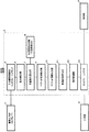
図1は、本実施形態にかかる画像解析装置SSの構成を示すブロック図である。 FIG. 1 is a block diagram showing the configuration of the image analysis apparatus SS according to the present embodiment.
画像解析装置SSは、入力データとしての動画像の入力を受け付ける画像入力部1、キーボード、タッチパネル、ジョグダイヤル又はその他の入力機構を備えユーザから入力された情報を制御部3へ出力する入力部2、入力データから出力データとしての画像又は動画像を生成する制御部3、ディスプレイ等を備え出力データを表示する表示部4等を備える。
The image analysis apparatus SS includes an
さらに詳細には、画像入力部1は、撮像領域内における動画像を撮像して所定の電気信号を出力する図示しないビデオカメラ(デジタルビデオカメラ)から、当該電気信号の入力を受け付ける。
More specifically, the
本実施形態では、ビデオカメラは、所定の施設(交通機関、商業施設、公共機関等)等に設置され、一定期間(例えば、1時間毎等、又は24時間連続して)、当該施設の所定の撮像領域内を撮像する。 In the present embodiment, the video camera is installed in a predetermined facility (transportation facility, commercial facility, public institution, etc.), etc., and for a certain period (for example, every hour, or continuously for 24 hours) The inside of the imaging area is imaged.
なお、ビデオカメラは、公知技術であるため詳しい説明は省略するが、例えば、光学系レンズから取り込まれた光が、絞り機構等によって調節され、CCD(Charge Couple Semiconductor)イメージセンサ又はCMOS(Complementary Metal-Oxide Semiconductor)イメージセンサ上に光学像(画像)として結像される。この画像は、イメージセンサによって電気信号に変換され、画像入力部1(カメラI/F)へ出力される。 The video camera is a well-known technique and will not be described in detail. For example, the light taken in from the optical lens is adjusted by a diaphragm mechanism or the like, and then a CCD (Charge Couple Semiconductor) image sensor or CMOS (Complementary Metal). -Oxide Semiconductor) An optical image (image) is formed on the image sensor. This image is converted into an electrical signal by the image sensor and output to the image input unit 1 (camera I / F).
そして、画像入力部1は、ビデオカメラから出力された電気信号を受け付け、前記画像を構成する画素を示す画素情報(前記各画素に対応する電気信号等)と前記画素に対応する色情報(R,G,Bの何れかの原色成分に対応した電荷等)を示す静止画像(後述するフレーム)として、例えば、撮像時刻と対応付けて制御部3(後述する入力画像格納部5)へ出力する。
Then, the
換言すれば、画像入力部1は、入力された動画像を所定フレーム(例えば、毎秒20フレーム(即ち、フレームレートが20fps(frame per second))等)の静止画像からなる画像情報に変換し、例えば、撮像時刻等と対応付けて制御部3へ出力する。即ち、これらのフレームが動画像を構成する。
In other words, the
画像入力部1の一例として、例えば、産業用デジタルカメラと画像入力ボードを接続する規格仕様である公知のカメラリンク(Camera Link)に対応したインターフェースが適用される。
As an example of the
制御部3は、詳しくは後述するが、動画像に示される解析対象が撮像領域内で示す単位時間当たりの位置変化をベクトル情報として算出し、当該ベクトル情報に基づいて、撮像領域の所定範囲内に存在するベクトル情報の代表的な方向を表示させる出力データを生成する。
As will be described in detail later, the
このような制御部3の動作(処理)は、制御部3内に実装されるハードウェア回路により行われるものであっても良いし、制御部3内に実装されるマイクロコンピュータ(CPU等)が所定のプログラム(ソフトウェア)を実行することにより行われるものであっても良い。
Such an operation (processing) of the
さらに具体的に、制御部3は、入力画像格納部5(本願の記憶手段の一例)、動体検出部6(本願の検出手段の一例)、位置変化算出部7(本願の位置変化算出手段の一例)、位置座標記憶部8(本願の位置変化算出手段の一例)、ベクトル情報算出部9(本願のベクトル情報算出手段の一例)、ベクトル情報抽出部10(本願のベクトル情報抽出手段の一例)、移動状態算出部11(本願の移動状態算出手段の一例)、表示制御部12(本願の表示制御手段の一例)、出力フレームメモリ13等から構成される。
More specifically, the
入力画像格納部5は、上記撮像領域内を一定期間撮像した動画像を記憶するための記憶領域であり、例えば、揮発性又は不揮発性メモリ又はハードディスク等が適用される。
The input
具体的に、本実施形態における入力画像格納部5は、一又は複数のフレーム(上述した動画像から所定フレームに変換された静止画像)と、各フレームにおける撮像時刻、及び詳しくは後述する座標値等を対応付けて記憶する。
Specifically, the input
そして、入力画像格納部5には、一定期間撮像された動画像に対応した複数のフレームが記憶されている。
The
動体検出部6は、動画像に示される解析対象を検出する。 The moving body detection unit 6 detects an analysis target indicated in the moving image.
撮像された動画像には、当該施設を利用する人や当該施設内を通過する移動手段(例えば、車や荷台等)等が示されている。本実施形態における動体検出部6は、この人や移動手段等を解析対象として検出するようになっている。 The captured moving image shows a person who uses the facility, a moving means (for example, a car, a loading platform, etc.) passing through the facility, and the like. The moving body detection unit 6 in the present embodiment detects this person, moving means, and the like as an analysis target.
この解析対象を検出する方法は、公知の技術であるため詳しい説明は省略するが、動体検出部6は、動画像を構成するフレームのうち基準となるフレームと、予め記憶された参照フレーム(同じ撮像領域内の静止画像)との画素間減算及び、いわゆる背景除去を行い、画像変化のあった画素のみの画像に変換する。そして、ノイズ除去及び2値化等の画像処理を施すと、当該基準となるフレームの解析対象が抽出される。そして、抽出された解析対象を他の解析対象と識別するためにラベリング処理を行い、各解析対象に動体ID(本願の解析対象識別情報の一例。)を付与する処理を行う。 Since the method for detecting the analysis target is a known technique, a detailed description thereof is omitted. However, the moving object detection unit 6 uses the reference frame (the same as the reference frame stored in advance) as the reference frame among the frames constituting the moving image. Subtraction between pixels with a still image in the imaging region) and so-called background removal are performed, and the image is converted to an image having only pixels that have changed. Then, when image processing such as noise removal and binarization is performed, an analysis target of the reference frame is extracted. Then, a labeling process is performed to identify the extracted analysis object from other analysis objects, and a process of assigning a moving object ID (an example of analysis object identification information of the present application) to each analysis object is performed.
この動体IDは、解析対象を他の解析対象と識別するための識別情報である。 This moving object ID is identification information for identifying the analysis target from other analysis targets.
位置変化算出部7は、検出された解析対象が、撮像領域内で示す位置変化を算出する。 The position change calculation unit 7 calculates a position change indicated by the detected analysis target in the imaging region.
この位置変化の算出には、例えば、公知の追跡処理を適用することができる。 For example, a known tracking process can be applied to the calculation of the position change.
追跡処理は公知の技術であるため詳しい説明は省略するが、まず、位置変化算出部7は、基準となるフレームで特定された解析対象が、当該基準となるフレームで示す撮像領域内の位置を特定する。 Since the tracking process is a well-known technique, a detailed description thereof will be omitted. First, the position change calculation unit 7 determines the position in the imaging region indicated by the reference frame as the analysis target specified by the reference frame. Identify.
次に、位置変化算出部7は、異なるフレーム(基準となるフレームより後で撮像されたフレーム)に当該解析対象と同一の物体が特定されるか判定する。 Next, the position change calculation unit 7 determines whether the same object as the analysis target is specified in a different frame (a frame captured after the reference frame).
この同一の物体として特定するための方法としては、例えば基準となるフレームで特定された解析対象の大きさや主軸の比等からなる形状パラメータを求め、他のフレームにおいて、この形状パラメータと最も近似する形状パラメータを有する物体を同一の解析対象とみなす等の方法を適用することができる。 As a method for specifying the same object, for example, a shape parameter including the size of the analysis target specified in the reference frame and a ratio of the main axes is obtained, and the shape parameter is most approximated in other frames. A method of considering an object having a shape parameter as the same analysis target can be applied.
そして、同一の物体であると判定された場合には、位置変化算出部7は、異なるフレームにおける解析対象が、当該異なるフレームで示す撮像領域内の位置を特定する。 When it is determined that they are the same object, the position change calculation unit 7 specifies the position in the imaging region indicated by the different frame as the analysis target in the different frame.
そして、位置変化算出部7は、特定した解析対象が基準となるフレームで示す撮像領域内の位置と、特定した解析対象が異なるフレームで示す撮像領域内の位置を、検出された解析対象が前記撮像領域内で示す位置変化として算出する。 Then, the position change calculation unit 7 detects the position in the imaging region indicated by the frame in which the identified analysis target is a reference and the position in the imaging region indicated by a frame in which the specified analysis target is different as the detected analysis target It is calculated as a position change indicated in the imaging area.
この位置変化は、一定期間撮像された動画像の連続するフレームの全てについて、解析対象毎に算出することができる。換言すれば、位置変化算出部7は、動画像に示される解析対象が、上記連続する各フレームにおいて示す撮像領域内の位置を、位置変化として算出することができる。 This change in position can be calculated for each analysis target for all consecutive frames of a moving image captured for a certain period. In other words, the position change calculation unit 7 can calculate, as a position change, the position in the imaging region indicated by the analysis target indicated by the moving image in each of the continuous frames.
この位置変化の算出によって、解析対象が、撮像領域内で示す位置変化(移動量、移動方向)を把握することができる。 By calculating the position change, the analysis object can grasp the position change (movement amount, movement direction) indicated in the imaging region.
位置座標記憶部8は、算出された位置変化を動体IDと対応付けて、解析対象毎に記憶するための記憶領域であり、例えば、揮発性又は不揮発性メモリ又はハードディスク等が適用される。 The position coordinate storage unit 8 is a storage area for storing the calculated position change in association with the moving object ID for each analysis target. For example, a volatile or nonvolatile memory or a hard disk is applied.
ベクトル情報算出部9は、上記記憶された位置変化に基づいて、検出された解析対象が、撮像領域内で示す単位時間当たりの位置変化を、当該撮像領域内における位置及び方向を含むベクトル情報として動体ID毎に算出する。 Based on the stored position change, the vector information calculation unit 9 uses the detected analysis target position change per unit time indicated in the imaging area as vector information including the position and direction in the imaging area. Calculated for each moving object ID.
このベクトル情報の算出は、公知の技術であるため詳しい説明は省略するが、以下のように算出される。 Since the calculation of the vector information is a known technique, detailed description thereof is omitted, but is calculated as follows.
上述したフレームは、動画像を所定間隔(所定期間)で分割したもの(例えば、上述した、毎秒20フレーム等)である。そして、位置変化算出部7は、上述したように、解析対象が、撮像領域内で示す位置変化を、連続するフレームの全てについて算出し、位置座標記憶部8に記憶されている。 The frame described above is obtained by dividing a moving image at a predetermined interval (predetermined period) (for example, 20 frames per second as described above). Then, as described above, the position change calculation unit 7 calculates the position change indicated by the analysis target in the imaging region for all the continuous frames and stores the position change in the position coordinate storage unit 8.
そして、ベクトル情報算出部9は、まず、位置座標記憶部8に記憶された、解析対象が撮像領域内で示す位置変化を用いて、解析対象が撮像領域内で示す単位時間当たりの位置変化を算出する。 Then, the vector information calculation unit 9 first uses the position change stored in the position coordinate storage unit 8 and indicated by the analysis target within the imaging region to calculate the position change per unit time indicated by the analysis target within the imaging region. calculate.
具体的には、例えば、フレームが動画像を毎秒20フレームで分割されたものであった場合(以下単に、「フレームレートが20fps」とする。)には、ベクトル情報算出部9は、位置変化算出部7によって特定された、解析対象が基準となるフレームで示す撮像領域内の位置と、当該基準となるフレームから21番目にあたるフレーム間で示す撮像領域内の位置を算出することにより、解析対象が前記撮像領域内で示す単位時間当たりの位置変化を算出する。 Specifically, for example, when the frame is a moving image divided at 20 frames per second (hereinafter simply referred to as “frame rate is 20 fps”), the vector information calculation unit 9 performs the position change. The analysis target is calculated by calculating the position in the imaging region indicated by the reference frame specified by the calculation unit 7 and the position in the imaging region indicated by the 21st frame from the reference frame. Calculates a position change per unit time indicated in the imaging region.
このように、フレームは、動画像を所定間隔で分割したものであるため、任意のフレーム間における解析対象が示す位置変化を算出することによって、解析対象の所定間隔当たりの位置変化を算出することができるのである。 As described above, since a frame is obtained by dividing a moving image at a predetermined interval, a position change per predetermined interval of the analysis target can be calculated by calculating a position change indicated by the analysis target between arbitrary frames. Can do it.
そして、ベクトル情報算出部9は、解析対象が、基準となるフレームで示す撮像領域内の位置を移動開始点と、当該基準となるフレームから20番目にあたるフレームで示す撮像領域内の位置を移動終了点として、解析対象が示す単位時間当たりのベクトル情報を算出する。 Then, the vector information calculation unit 9 ends the movement of the position in the imaging region indicated by the frame corresponding to the 20th frame from the reference frame, as the analysis target position in the imaging region indicated by the reference frame. As a point, vector information per unit time indicated by the analysis target is calculated.
このベクトル情報は、検出された解析対象が、前記撮像領域内で示す単位時間当たりの位置変化を、前記撮像領域内における位置及び方向を含む情報として算出したものであり、この情報を、以下単に、ベクトル情報とする。また、上述した追跡処理において、このベクトル情報を算出するようにしてもよい。 This vector information is obtained by calculating the position change per unit time indicated by the detected analysis target in the imaging region as information including the position and direction in the imaging region. And vector information. Further, the vector information may be calculated in the tracking process described above.
なお、上述した例では、単位時間を1秒として想定したが、これに限定されず、例えば、単位時間を任意の時間に設定することができる。 In the above-described example, the unit time is assumed to be 1 second. However, the present invention is not limited to this. For example, the unit time can be set to an arbitrary time.
例えば、この単位時間を5秒とした場合を考える。この場合、フレームレートが20fpsであった場合には、ベクトル情報算出部9が、位置変化算出部7によって特定された、解析対象が基準となるフレームで示す撮像領域内の位置と、当該基準となるフレームから100番目にあたるフレーム間で示す撮像領域内の位置を算出することにより、解析対象が前記撮像領域内で示す単位時間当たりの位置変化が算出されることとなる。 For example, consider the case where the unit time is 5 seconds. In this case, when the frame rate is 20 fps, the vector information calculation unit 9 specifies the position in the imaging region indicated by the frame based on the analysis target specified by the position change calculation unit 7, the reference, By calculating the position in the imaging region indicated between the frames corresponding to the 100th frame from the frame, the change in position per unit time indicated by the analysis target in the imaging region is calculated.
ベクトル情報抽出部10は、上記ベクトル情報に含まれる位置に基づいて、前記撮像領域の所定範囲内に存在するベクトル情報を、動体ID毎に抽出する。
The vector
移動状態算出部11は、ベクトル情報抽出部10によって抽出された所定範囲内に存在するベクトル情報に含まれる方向に基づいて、当該所定範囲内に存在するベクトル情報の一又は複数の代表的な方向を算出する。
Based on the direction included in the vector information existing within the predetermined range extracted by the vector
表示制御部12は、移動状態算出部11によって算出された代表的な方向を、外部へ表示させる。
The
出力フレームメモリ13は、出力データを書込むための制御を行う。
The
[2.動画像から検出された解析対象が、撮像領域内で示す位置変化を記憶するまでの画像解析装置SSの動作]
次に、動画像から検出された解析対象が、撮像領域内で示す位置変化を記憶するまで(主として動体検出部6、及び位置変化算出部7の動作)の画像解析装置SSの動作の詳細について、図2〜図7を用いて説明する。
[2. Operation of the image analysis apparatus SS until the analysis target detected from the moving image stores the position change indicated in the imaging region]
Next, details of the operation of the image analysis apparatus SS until the analysis target detected from the moving image stores the position change indicated in the imaging region (mainly the operation of the moving object detection unit 6 and the position change calculation unit 7). This will be described with reference to FIGS.
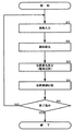
図2は、動画像から検出された解析対象が、撮像領域内で示す位置変化を記憶するまでの画像解析装置SSの動作の詳細を示すフローチャートである。 FIG. 2 is a flowchart showing details of the operation of the image analysis apparatus SS until the analysis target detected from the moving image stores the position change shown in the imaging region.
図2に示すように、画像入力部1から出力される撮像時刻と対応付けられたフレームが入力されると(ステップS1)、フレームと、各フレームにおける撮像時刻が対応付けられて、入力画像格納部5に記憶される。
As shown in FIG. 2, when a frame associated with the imaging time output from the
さらに、このフレームには、上述した座標値が対応付けて記憶される。 Furthermore, the coordinate values described above are stored in association with this frame.
この座標値は、フレームに示される撮像領域内の所定の位置を、他の位置と識別するための値であり、例えばフレームの水平方向をX軸と、フレームの垂直方向をY軸とする平面座標系におけるX,Y座標で表わされる。 This coordinate value is a value for discriminating a predetermined position in the imaging area indicated by the frame from other positions, for example, a plane having the horizontal direction of the frame as the X axis and the vertical direction of the frame as the Y axis. It is represented by X and Y coordinates in the coordinate system.
ここで、入力画像格納部5に記憶されるフレームの一例について図3を用いて説明する。
Here, an example of a frame stored in the input
図3は、入力画像格納部5に記憶されるフレームの一例を示す図である。
FIG. 3 is a diagram illustrating an example of a frame stored in the input
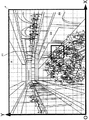
図3に示すフレームFは、店舗S1〜S4が設置されたショッピングモールSの所定の撮像領域内を、一定期間撮像された動画像から変換されたフレームのうち一のフレームである。 A frame F shown in FIG. 3 is one of the frames converted from a moving image captured in a predetermined period in a predetermined imaging area of the shopping mall S where the stores S1 to S4 are installed.
このフレームFには、ショッピングモールSを利用する人等が示されており、全てのフレームで統一された上記座標値が設定されている。 In this frame F, people who use the shopping mall S are shown, and the coordinate values unified in all the frames are set.
この座標値によって、フレームに示される解析対象(人や店舗等。以下代表して「人」と示す。)の位置を、X座標値及びY座標値で表わすことができる。従って、フレームに示されるそれぞれの人や店舗が、フレームに示される撮像領域内の位置を特定することができる。 With this coordinate value, the position of an analysis target (a person, a store, etc., which will be represented as “person” hereinafter) shown in the frame can be represented by an X coordinate value and a Y coordinate value. Therefore, each person or store indicated in the frame can specify the position in the imaging region indicated in the frame.
入力画像格納部5には、一定期間撮像された動画像に対応した複数のフレームが記憶されている。
The input
次に、動体検出部6は、解析対象として人をそれぞれ検出し、検出した人毎に動体IDを付与する(ステップS2)。例えば、図3のフレームFに示される人毎に動体IDが付与される。 Next, the moving object detection unit 6 detects each person as an analysis target and assigns a moving object ID to each detected person (step S2). For example, a moving object ID is assigned to each person shown in the frame F of FIG.
次に、位置変化算出部7は、上述した追跡処理(動体追跡)を行い、検出された人の位置変化を算出する。(ステップS3)。 Next, the position change calculation unit 7 performs the tracking process (moving body tracking) described above, and calculates the detected position change of the person. (Step S3).
ここで、位置変化の算出例について、図4を用いて説明する。 Here, a calculation example of the position change will be described with reference to FIG.
図4は、所定期間内における人の移動を示す概念図である。 FIG. 4 is a conceptual diagram showing movement of a person within a predetermined period.
図4に示すように、例えば、人H1(解析対象の一例)が、位置としてV1s(x1、y1)からV10e(x11、y11)まで移動した場合(図の破線部で表わした矢印まで移動)を考える。 As shown in FIG. 4, for example, when a person H1 (an example of an analysis target) moves from V 1s (x1, y1) to V 10e (x11, y11) as a position (up to an arrow indicated by a broken line in the figure) Move).
この場合、位置変化算出部7は、人H1がV1s(x1、y1)に位置することが示されたフレームを基準として、人H1がV10e(x11、y11)に位置することが示されたフレームまで、人H1が各フレーム毎で示す位置を座標値で算出する。この算出された座標値が、人H1が、撮像領域内で示す位置変化となるのである。 In this case, the position change calculation unit 7 indicates that the person H1 is located at V 10e (x11, y11) with reference to the frame in which the person H1 is located at V 1s (x1, y1). The position indicated by the person H1 for each frame is calculated as a coordinate value up to the next frame. This calculated coordinate value is the position change that the person H1 shows in the imaging region.
また、位置変化算出部7は、動画像に示される全ての人(すべての動体ID)に対して位置変化を算出することもできる。 The position change calculation unit 7 can also calculate position changes for all persons (all moving body IDs) shown in the moving image.
次に、位置座標記憶部8は、人H1に対して算出した位置変化を、人H1を示す動体IDと対応付けて位置座標DBとして記憶する(ステップS4)。 Next, the position coordinate storage unit 8 stores the position change calculated for the person H1 as a position coordinate DB in association with the moving object ID indicating the person H1 (step S4).
図5は、位置座標DBに記憶される内容の一例を示す図である。 FIG. 5 is a diagram illustrating an example of contents stored in the position coordinate DB.
図5に示す位置座標DBには、動体ID(例えば、人H1)と、動体IDが示す人H1が撮像領域内で示す位置としての位置座標、当該位置における時刻(フレームとして撮像された撮像時刻)が対応付けられて記憶される。 The position coordinate DB illustrated in FIG. 5 includes a moving object ID (for example, a person H1), a position coordinate as a position indicated by the person H1 indicated by the moving object ID in the imaging region, and a time at the position (imaging time when the image is captured as a frame). ) Are stored in association with each other.
このように、動体IDが示す人H1が撮像領域内で示す位置と、当該位置における時刻を対応付けて記憶することにより、人H1が、撮像領域内で示す位置変化を記憶することができる。 Thus, by storing the position indicated by the moving object ID in the imaging area in association with the position indicated by the person H1 and the time at the position, the person H1 can store the change in position indicated in the imaging area.
なお、位置座標DBには、動画像に示される全ての人に対して算出された位置変化を記憶することもできる。 In the position coordinate DB, position changes calculated for all persons shown in the moving image can be stored.
そして、終了指示があった場合には(ステップS5:YES)、処理を終了し、終了指示がない場合には(ステップS5:NO)、ステップS1の処理へ移行する。 If there is an end instruction (step S5: YES), the process ends. If there is no end instruction (step S5: NO), the process proceeds to step S1.
[3.算出したベクトル情報に基づいて撮像領域の所定範囲内に存在するベクトル情報の一又は複数の代表的な方向を表示させるまでの画像解析装置SSの動作]
次に、算出したベクトル情報に基づいて撮像領域の所定範囲内に存在するベクトル情報の一又は複数の代表的な方向を表示させるまでの画像解析装置SSの動作の詳細について、図6〜図14を用いて説明する。
[3. Operation of image analysis apparatus SS until one or more representative directions of vector information existing within a predetermined range of the imaging region are displayed based on the calculated vector information]
Next, details of the operation of the image analysis apparatus SS until displaying one or more representative directions of vector information existing within a predetermined range of the imaging region based on the calculated vector information will be described with reference to FIGS. Will be described.
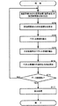
図6は、算出したベクトル情報に基づいて撮像領域の所定範囲内に存在するベクトル情報の代表的な方向を表示させるまでの画像解析装置SSの動作の詳細を示すフローチャートである。 FIG. 6 is a flowchart showing details of the operation of the image analysis apparatus SS until the representative direction of the vector information existing within the predetermined range of the imaging region is displayed based on the calculated vector information.
図6に示すように、まず、ベクトル情報算出部9は、例えばユーザによる入力部2の指示により又は、予め設定された指示に基づいて、撮像された動画像から、人H1が、撮像領域内で示す所定期間分の位置変化を取得する(ステップS11)。
As shown in FIG. 6, first, the vector information calculation unit 9 causes the person H1 to move from the captured moving image within the imaging area based on, for example, an instruction of the
具体的には、ベクトル情報算出部9は、位置座標DBを参照して、動体IDが、所定期間に示した位置座標を取得する。例えば、所定期間として1時間が設定されていた場合には、ベクトル情報算出部9は、動体IDと対応付けて記憶された時刻と、当該時刻と対応付けて記憶された位置座標を参照して、1時間分の位置座標を、所定期間分の位置変化として取得する。 Specifically, the vector information calculation unit 9 refers to the position coordinate DB, and the moving object ID acquires the position coordinates indicated in the predetermined period. For example, when 1 hour is set as the predetermined period, the vector information calculation unit 9 refers to the time stored in association with the moving object ID and the position coordinates stored in association with the time. Position coordinates for one hour are acquired as position changes for a predetermined period.
この所定期間分の位置変化は、一の動体IDに対して取得してもよいし、全ての動体IDに対して取得してもよい。 The position change for the predetermined period may be acquired for one moving object ID or may be acquired for all moving object IDs.
なお、ベクトル情報算出部9は、上記取得する位置変化として、所定期間に区切られたものに限らず、例えば、動画像に示される全ての位置変化を取得するようにしてもよい。 Note that the vector information calculation unit 9 is not limited to the position change acquired in the above-described period, and may acquire all position changes indicated in the moving image, for example.
次に、ベクトル情報算出部9は、上記取得した所定期間分の位置変化に基づいて、単位時間当たりの位置変化を算出する(ステップS12)。 Next, the vector information calculation unit 9 calculates a position change per unit time based on the acquired position change for a predetermined period (step S12).
ここで、単位時間当たりの位置変化の算出について、図4及び図7を用いて説明する。 Here, the calculation of the position change per unit time will be described with reference to FIGS.
図7は、人H1の単位時間当たりの位置変化の算出例を示す概念図である。 FIG. 7 is a conceptual diagram illustrating a calculation example of the position change per unit time of the person H1.
先に示した図4において、人H1が、所定期間の間に、V1s(x1、y1)からV10e(x11、y11)まで移動した場合の単位時間当たりの位置変化を算出する例を説明する。 In the above-described FIG. 4, an example in which the position change per unit time when the person H1 moves from V 1s (x1, y1) to V 10e (x11, y11) during a predetermined period will be described. To do.
ここで、単位時間当たりの位置変化とは、基準となるフレームで人H1が示す位置を移動開始点とし、当該フレームから単位時間後(例えば1秒後)のフレームで人H1が示す位置を移動終了点とした場合の位置変化を示す。 Here, the position change per unit time means that the position indicated by the person H1 in the reference frame is the movement start point, and the position indicated by the person H1 is moved in a frame after a unit time (for example, 1 second) from the frame. The position change when it is set as the end point is shown.
この算出方法について具体的には、人H1が、V1s(x1、y1)からV10e(x11、y11)まで移動した場合の単位時間当たりの位置変化を求めるには、V1s(x1、y1)を基準として、単位時間毎(例えば1秒間隔)のフレームにおける人H1の位置を特定すればよい。 Specifically for this calculation method, human H1 is, in order to determine the position change per unit time in the case of moving from V 1s (x1, y1) to V 10e (x11, y11), V 1s (x1, y1 ) As a reference, the position of the person H1 in a frame every unit time (for example, every 1 second) may be specified.
さらに具体的には、基準となるフレームで人H1が示す位置がV1s(x1、y1)であり、当該フレームから単位時間後のフレームで人H1が示す位置がV1e(x2、y2)であったとすると、単位時間当たりの位置変化は、移動開始点としてのV1s(x1、y1)から、移動終了点としてのV1e(x2、y2)までの位置変化であると算出される。 More specifically, the position indicated by the person H1 in the reference frame is V 1s (x1, y1), and the position indicated by the person H1 in a frame after a unit time from the frame is V 1e (x2, y2). If there is, the position change per unit time is calculated as the position change from V 1s (x1, y1) as the movement start point to V 1e (x2, y2) as the movement end point.
次に、ベクトル情報算出部9は、V1e(x2、y2)を基準に、単位時間後のフレームにおける人H1の位置を特定し、単位時間当たりの位置変化を算出する。そして、ベクトル情報算出部9は、人H1が、V10e(x11、y11)に至るまでの単位時間当たりの位置変化を、順次算出する。 Next, the vector information calculation unit 9 specifies the position of the person H1 in the frame after the unit time based on V 1e (x2, y2), and calculates the position change per unit time. The vector information calculation unit 9, human H1 is, the position change per unit time until V 10e (x11, y11), successively calculated.
このようにして算出された、人H1が、V1s(x1、y1)からV10e(x11、y11)まで移動した場合の単位時間当たりの位置変化の算出結果を、図7に示す。 FIG. 7 shows the calculation result of the position change per unit time when the person H1 calculated in this way moves from V 1s (x1, y1) to V 10e (x11, y11).
図7に示すように、人H1が、V1s(x1、y1)からV10e(x11、y11)まで移動した場合の単位時間当たりの位置変化として、まず、移動開始点としてV1s(x1、y1)から、単位時間後のフレームに示される人H1の位置を移動終了点としてV1e(x2、y2)とした、最初の単位時間当たりの位置変化が算出されている。 As shown in FIG. 7, as a change in position per unit time when a person H1 moves from V 1s (x1, y1) to V 10e (x11, y11), first, V 1s (x1, From y1), the first position change per unit time is calculated with the position of the person H1 indicated in the frame after the unit time as V 1e (x2, y2) with the movement end point.
次に、移動開始点をV2s(x2、y2)、移動終了点をV2e(x3、y3)とした次の単位時間当たりの位置変化が、そして、移動開始点をV3s(x3、y3)、移動終了点をV3e(x4、y4)とした次の単位時間当たりの位置変化が、そして、移動開始点をV10s(x10、y10)、移動終了点をV10e(x11、y11)とした最後の単位時間当たりの位置変化まで、単位時間当たりの位置変化が順次算出されている。 Next, the next position change per unit time with the movement start point as V 2s (x2, y2) and the movement end point as V 2e (x3, y3), and the movement start point as V 3s (x3, y3). ), The next position change per unit time with the movement end point being V 3e (x4, y4), the movement start point is V 10s (x10, y10), and the movement end point is V 10e (x11, y11). The position change per unit time is sequentially calculated up to the last position change per unit time.
なお、上述した例では、ある単位時間当たりの位置変化の移動終了点と、当該位置変化の次に算出される単位時間当たりの位置変化の移動開始点(例えば、V1eとV2s等)は同一の点を示すこととなるが、図7においては説明の便宜上、互いに接する点として表している。 In the above-described example, the movement end point of the position change per unit time and the movement start point of the position change per unit time calculated after the position change (for example, V 1e and V 2s ) are Although the same point is shown, in FIG. 7, it represents as a point which mutually contacts for convenience of explanation.
また、図7に示す例では、説明の便宜上、算出された単位時間当たりの位置変化を、所定のフレームに重畳して表示させている。 In the example shown in FIG. 7, for convenience of explanation, the calculated position change per unit time is displayed superimposed on a predetermined frame.
また、位置変化算出部7は、動画像に示される全ての人(すべての動体ID)に対して位置変化を算出することもできる。 The position change calculation unit 7 can also calculate position changes for all persons (all moving body IDs) shown in the moving image.
次に、ベクトル情報算出部9は、上記算出された単位時間当たりの位置変化を、撮像領域内における位置及び方向を含むベクトル情報として算出する(ステップS13)。 Next, the vector information calculation unit 9 calculates the calculated position change per unit time as vector information including the position and direction in the imaging region (step S13).
このベクトル情報は、例えば、移動開始点がV1s(x1、y1)、移動終了点がV1e(x2、y2)である単位時間当たりの位置変化に着目すると、
ベクトル情報V1は、一般的に、(x2−x1、y2−y1)で算出されることが知られている。ここで、上記移動開始点は所謂ベクトルの始点であり、上記移動終了点は所謂ベクトルの終点である。
For example, when the vector information focuses on a change in position per unit time where the movement start point is V 1s (x1, y1) and the movement end point is V 1e (x2, y2),
Vector information V 1 was generally known to be calculated by (x2-x1, y2-y1 ). Here, the movement start point is a so-called vector start point, and the movement end point is a so-called vector end point.
このベクトル情報V1は、大きさと向きを持つ量であるため、人H1が撮像領域内で示す単位時間当たりの位置変化を把握することができる。 The vector information V 1 was, since an amount having a magnitude and direction, can be human H1 is to grasp the position change per unit time indicated in the imaging area.
そして、ベクトル情報算出部9は、算出された単位時間当たりの位置変化の数量に対応した数量のベクトル情報を算出する。 Then, the vector information calculation unit 9 calculates a quantity of vector information corresponding to the calculated position change quantity per unit time.
ここで、ベクトル情報の算出結果について、図8を用いて説明する。 Here, the calculation result of vector information is demonstrated using FIG.
図8は、人H1の単位時間当たりの位置変化の数量に対応した数量のベクトル情報の算出結果を示す概念図である。 FIG. 8 is a conceptual diagram showing a calculation result of the quantity vector information corresponding to the quantity of position change per unit time of the person H1.
図8に示すように、移動開始点をV1s(x1、y1)、移動終了点をV1e(x2、y2)としたベクトル情報V1を最初のベクトル情報として、移動開始点をV2s(x2、y2)、移動終了点をV2e(x3、y3)としたベクトル情報V2、移動開始点をV3s(x3、y3)、移動終了点をV3e(x4、y4)としたベクトル情報V3が、移動開始点をV10s(x10、y10)、移動終了点をV10e(x11、y11)としたベクトル情報V10まで順次算出される。 As shown in FIG. 8, vector information V 1 having the movement start point as V 1s (x1, y1) and the movement end point as V 1e (x2, y2) is set as the first vector information, and the movement start point is set as V 2s ( Vector information V 2 with x2, y2), movement end point V 2e (x3, y3), vector information with movement start point V 3s (x3, y3), and movement end point V 3e (x4, y4) V 3 is sequentially calculated up to vector information V 10 with the movement start point as V 10s (x10, y10) and the movement end point as V 10e (x11, y11).
なお、上述した例では、あるベクトル情報の移動終了点と、当該ベクトル情報の次に算出されるベクトル情報の移動開始点は同一の点を示すこととなるが、図8においては説明の便宜上、互いに接する点として表している。 In the example described above, the movement end point of certain vector information and the movement start point of the vector information calculated next to the vector information indicate the same point. However, in FIG. It is expressed as points that touch each other.
なお、図8に示す例では、算出されたベクトル情報を、所定のフレームに重畳して表示させている。 In the example shown in FIG. 8, the calculated vector information is displayed superimposed on a predetermined frame.
上述したように、ベクトル情報は、移動開始点及び移動終了点(位置)を含む情報である。従って、移動開始点及び移動終了点を、フレームの座標値の対応する位置に配置させることによって、算出されたベクトル情報を、所定のフレームの対応する位置に重畳して表示させることができる。 As described above, the vector information is information including a movement start point and a movement end point (position). Therefore, by arranging the movement start point and the movement end point at the positions corresponding to the coordinate values of the frame, the calculated vector information can be displayed superimposed on the corresponding position of the predetermined frame.
このように表示させることによって、撮像領域内における人の行動を視覚的に把握させ、解析結果に対する把握性の向上等が図られる。 By displaying in this way, it is possible to visually grasp the behavior of a person in the imaging region and improve the graspability of the analysis result.
また、ベクトル情報V1の大きさは、一般的に、((x2−x1)2+(y2−y1)2)1/2で算出されることが知られている。 Further, it is known that the size of the vector information V 1 is generally calculated by ((x2−x1) 2 + (y2−y1) 2 ) 1/2 .
このフレームに示されるベクトル情報V1の大きさと、撮像領域内における現実(実世界)の大きさと、の相関を算出することによって、フレームに示されるベクトル情報V1の大きさが、撮像領域内においてどの程度の大きさを示すのか把握することができる。 And the magnitude of the vector information V 1 shown in this frame, the size of the real (real world) in the imaging area, by calculating a correlation, the magnitude of the vector information V 1 shown in the frame, the imaging area It can be grasped how much size is shown in.
即ち、フレームで示されるX,Y座標値の値を、実世界の大きさであるメートル(m)等に変換することによって、フレームに示されるベクトル情報V1の大きさが、撮像領域内においてどの程度の大きさを示すのか把握することができる(即ち、撮像領域内における現実の距離を把握することができる)。 Ie, X represented by the frame, the value of the Y coordinate value, by converting the real world it is sized meters (m) or the like, the magnitude of the vector information V 1 shown in the frame, in the imaging area It is possible to grasp how large the image is (that is, it is possible to grasp an actual distance in the imaging region).
そして、ベクトル情報算出部9は、動画像に示される全ての人(すべての動体ID)に対して、ステップS11で設定した所定期間分、又は入力される動画像が撮像された一定期間分のベクトル情報を算出することもできる。 Then, the vector information calculation unit 9 for all persons (all moving body IDs) indicated in the moving image for the predetermined period set in step S11 or for a certain period during which the input moving image is captured. Vector information can also be calculated.
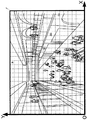
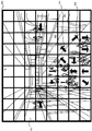
図9は、動画像に示される全ての人に対してベクトル情報を算出した場合の算出結果を示す概念図である。 FIG. 9 is a conceptual diagram showing a calculation result when vector information is calculated for all persons shown in the moving image.
図9では、動画像に示される全ての人に対してベクトル情報を算出し、所定のフレームに重畳して表示させている。 In FIG. 9, vector information is calculated for all people shown in the moving image and is displayed superimposed on a predetermined frame.
図9に示すように、画像に示される全ての人に対してベクトル情報を算出し、所定のフレームに重畳して表示させた場合には、解析対象の増加に伴って表示されるベクトル情報の数も増加するため、各解析対象に対応した個別のベクトル情報の向きや大きさ、又はベクトル情報の数量等を識別することが困難となり、解析結果に対する把握性が著しく低下してしまう。 As shown in FIG. 9, when the vector information is calculated for all persons shown in the image and displayed superimposed on a predetermined frame, the vector information displayed as the number of objects to be analyzed increases. Since the number also increases, it becomes difficult to identify the direction and size of individual vector information corresponding to each analysis object, the quantity of vector information, and the like, and the graspability for the analysis result is significantly lowered.
そこで本実施形態では、上記撮像領域の所定範囲内に存在するベクトル情報を抽出し、この抽出された所定範囲内に存在するベクトル情報に含まれる方向に基づいて、当該所定範囲内に存在するベクトル情報の一又は複数の代表的な方向を算出し、表示させるようになっている。 Therefore, in the present embodiment, vector information existing within a predetermined range of the imaging area is extracted, and a vector existing within the predetermined range is extracted based on a direction included in the extracted vector information within the predetermined range. One or more representative directions of information are calculated and displayed.
具体的には、ユーザによる入力部2の指示により又は、予め設定された指示に基づいて、上記撮像領域内の所定範囲内を指定する命令を受け付けると、ベクトル情報抽出部10は、当該撮像領域内の所定範囲内に存在するベクトル情報を抽出する(ステップS14)。
Specifically, upon receiving an instruction for designating a predetermined range in the imaging area based on an instruction of the
さらに具体的には、例えば、当該撮像領域内の所定範囲内として、図9の矩形領域20が指定(例えば、矩形領域20の定点を示す座標値を入力され、又は表示画面上に表示されるポインタ等で矩形領域を描かせる等により)されたとする。すると、ベクトル情報抽出部10は、座標値を参照して、矩形領域20に存在するベクトル情報を抽出する。
More specifically, for example, the
図10は、矩形領域20に存在するベクトル情報を抽出した抽出例を示す概念図である。
FIG. 10 is a conceptual diagram illustrating an extraction example in which vector information existing in the
図10に示すように、矩形領域20に存在するベクトル情報としてベクトル情報V1〜Vnが抽出されている。
As shown in FIG. 10, vector information V 1 to V n is extracted as vector information existing in the
なお、実際には、識別不可能なほど多数のベクトル情報が抽出される場合もあるが、図10では説明の便宜上、ベクトル情報の数量を限定して表記する。また、ベクトル情報の長さは、解析対象である人の単位時間当たりの移動距離に応じて異なるものであるが、図10では説明の便宜上、ベクトル情報の長さは略同一で表記する。 In actuality, there are cases where a large number of vector information items are extracted such that they cannot be identified, but in FIG. 10, for the convenience of explanation, the quantity of vector information items is limited. Further, the length of the vector information varies depending on the movement distance per unit time of the person to be analyzed, but in FIG. 10, for the convenience of explanation, the length of the vector information is shown as substantially the same.
また、上述した例と同様に全てのベクトル情報には、移動開始点及び移動終了点が含まれているが、図10では説明の便宜上、代表するベクトル情報(ベクトル情報V1及びベクトル情報Vn)にのみその図示を行い、その他の図示を省略する。 Further, as in the above-described example, all vector information includes a movement start point and a movement end point. However, for convenience of explanation in FIG. 10, representative vector information (vector information V 1 and vector information V n is included). ) Only, and the other illustrations are omitted.
このベクトル情報の抽出方法は、種々の方法を適用することができ、例えば、矩形領域20に、ベクトル情報の移動開始点が存在する場合に、ベクトル情報抽出部10は、当該ベクトル情報を抽出するようにしてもよい。
Various methods can be applied to this vector information extraction method. For example, when a movement start point of vector information exists in the
具体的に、ベクトル情報V1を例に説明すると、ベクトル情報V1の移動開始点V1Sが矩形領域20に含まれている場合に、ベクトル情報抽出部10は、当該ベクトル情報を抽出する。
Specifically, when describing the vector information V 1 as an example, if the movement start point V 1S vector information V 1 is included in the
これにより、矩形領域20にベクトル情報の移動開始点のみが存在する場合(即ち、これから矩形領域20から退出(通過)する動きを示すベクトル情報)についても、ベクトル情報抽出部10は、当該ベクトル情報を抽出するため、矩形領域20から退出する解析対象の動きを正確に解析することができる。
As a result, even when only the movement start point of the vector information exists in the rectangular area 20 (that is, vector information indicating a motion that leaves (passes) the
また、矩形領域20に、ベクトル情報の移動終了点が存在する場合に、ベクトル情報抽出部10は、当該ベクトル情報を抽出するようにしてもよい。
Further, when the movement end point of the vector information exists in the
具体的に、ベクトル情報V1の移動終了点V1eが矩形領域20に含まれている場合に、ベクトル情報抽出部10は、当該ベクトル情報を抽出する。
Specifically, when the movement end point V 1e of the vector information V 1 is included in the
これにより、矩形領域20にベクトル情報の移動終了点のみが存在する場合(即ち、矩形領域20へ進入する動きを示すベクトル情報)についても、ベクトル情報抽出部10は、当該ベクトル情報を抽出するため、矩形領域20から進入する解析対象の動きを正確に解析することができる。
Thus, if the
次に、移動状態算出部11は、矩形領域20に存在するベクトル情報に含まれる方向に基づいて、当該ベクトル情報の代表的な方向を算出する(ステップS15)。
Next, the movement
繰り返すが、ベクトル情報は、上述したように解析対象の移動(動き)に応じて様々な方向を示すこととなる。このような解析対象の動きに応じたベクトル情報を表示させると、各解析対象に対応した個別のベクトル情報を識別することが困難となる原因となる。 Again, the vector information indicates various directions according to the movement (motion) of the analysis target as described above. If such vector information corresponding to the motion of the analysis target is displayed, it becomes difficult to identify individual vector information corresponding to each analysis target.
そこで、移動状態算出手段11は、矩形領域20に存在するベクトル情報の代表的な方向を算出するのである。
Therefore, the movement
以下に、ステップS15の処理の詳細について説明する。 Details of the process in step S15 will be described below.
本実施形態では、移動状態算出部11は、第1の座標系(小領域モデル)を用いて、この代表的な方向を算出する。
In the present embodiment, the movement
ここで、第1の座標系について、図11を用いて説明する。 Here, the first coordinate system will be described with reference to FIG.
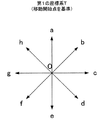
図11は、第1の座標系を示す図である。 FIG. 11 is a diagram illustrating the first coordinate system.
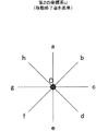
図11に示すように、第1の座標系Tは、原点0を中心に、原点0から背離する方向を示す方向軸a〜h(本願の原点を中心に所定の方向を示す方向軸の一例)が、原点0を中心に互いに45°(本願の所定の角度の一例)離れて8つ(本願の複数の一例)設けられている。即ち、第1の座標系Tは、平面座標系を8分割した座標軸である。
As shown in FIG. 11, the first coordinate system T has a direction axis a to h indicating the direction away from the
そして、移動状態算出部11は、矩形領域20に存在するベクトル情報に含まれる方向が、第1の座標系Tにおける何れかの方向軸a〜hが示す方向と近似するかを判定する。
Then, the movement
この近似を判定する方法としては種々の方法を適用することができるが、その一例について、図12を用いて説明する。 Various methods can be applied as a method for determining this approximation, and an example thereof will be described with reference to FIG.
図12は、近似を判定する方法を示す概念図である。 FIG. 12 is a conceptual diagram illustrating a method for determining approximation.
上記近似の判定に際しては、移動状態算出部11は、一の方向軸が示す方向と近似する範囲について予め定められたデータを参照する。
When determining the approximation, the movement
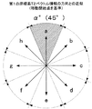
この近似する範囲としては、例えば、原点0を中心として、一の方向軸を仮想的に所定の角度の範囲で回転させた場合に、当該仮想的に回転させた方向軸が、当該所定の角度の範囲においてそれぞれ示す全ての方向が、近似する範囲として定められる。
As the approximate range, for example, when one direction axis is virtually rotated within a predetermined angle range around the
具体的には、図12に示すように、一の方向軸として方向軸aが示す方向と近似する範囲については、原点0を中心として、方向軸aを仮想的に一の方向へ22.5°、逆方向へ22.5°回転(即ち、原点0を中心に方向軸aを45°の範囲内で回転)させた場合に、当該仮想的に回転させた方向軸aが、一の方向へ22.5°、逆方向へ22.5°回転させた場合にそれぞれ示す全ての方向が、方向軸aが示す方向と近似する範囲にあると判定される。すなわち、方向軸aが示す方向と近似する範囲は、図12の斜線部で示した範囲が該当することとなる。
Specifically, as shown in FIG. 12, for a range approximating the direction indicated by the direction axis a as one direction axis, the direction axis a is virtually 22.5 in the one direction with the
このように、移動状態算出部11は、第1の座標系Tを用いて、一又は複数の代表的な方向を算出することによって、ベクトル情報の移動開始点を基準に近似する範囲を判定するため装置(CPU等)の処理負担を軽減しつつ、撮像領域の所定範囲内から退出する解析対象の動きを正確に解析することができる。
As described above, the movement
以下、上述した方向軸が示す方向と近似する範囲を、単に「近似する範囲」と称する。 Hereinafter, a range that approximates the direction indicated by the directional axis is simply referred to as an “approximate range”.
なお、図12に示す例では、方向軸b〜方向軸hが示す方向と近似する範囲についても、方向軸aと同様に定められている。 In the example illustrated in FIG. 12, the range that approximates the direction indicated by the direction axis b to the direction axis h is also determined in the same manner as the direction axis a.
また、この近似する範囲の設定方法は上述した例に限られず、任意に設定することができる。具体的には、一の方向軸と他の方向軸に対して、近似する範囲を異なるように設定してもよい。 The method for setting the approximate range is not limited to the above-described example, and can be arbitrarily set. Specifically, the approximate range may be set differently for one direction axis and the other direction axis.
また、上述した例では、平面座標系を8分割した方向軸a〜方向軸hを用いて近似する範囲を判定するようになっているが、これに限られず、例えば、平面座標系を任意の方向軸で分割した座標軸を用いるようにしてもよい(例えば、4分割、6分割等)。 In the above-described example, the approximate range is determined using the direction axis a to the direction axis h obtained by dividing the planar coordinate system into eight. However, the present invention is not limited to this. You may make it use the coordinate axis divided | segmented by the direction axis (for example, 4 divisions, 6 divisions, etc.).
そして、ステップS15の処理として、移動状態算出部11は、矩形領域20に存在するベクトル情報に含まれる移動開始点を、第1の座標系Tの原点に仮想的に移動する。そして、移動状態算出部11は、移動させたベクトル情報に含まれる方向が、第1の座標系Tにおける何れかの方向軸a〜hの近似する範囲に該当するか判定する。
Then, as the process of step S <b> 15, the movement
ここで、図13を用いて、移動状態算出部11が、移動させたベクトル情報に含まれる方向が、第1の座標系Tにおける何れかの方向軸の近似する範囲に該当するかを判定した判定結果について説明する。
Here, with reference to FIG. 13, the movement
図13は、移動させたベクトル情報に含まれる方向が、第1の座標系Tにおける何れかの方向軸の近似する範囲に該当するかを判定した判定結果を示す図である。 FIG. 13 is a diagram illustrating a determination result obtained by determining whether the direction included in the moved vector information corresponds to a range approximated by any of the direction axes in the first coordinate system T.
図13に示すように、ベクトル情報V1の移動開始点V1Sが、原点0に仮想的に移動され、ベクトル情報V1に含まれる方向が、方向軸fの近似する範囲に含まれている。
As illustrated in FIG. 13, the movement start point V 1S of the vector information V 1 is virtually moved to the
従って、移動状態算出部11は、ベクトル情報V1は、方向軸fが示す方向に近似すると判断する。
Accordingly, the moving
そして、移動状態算出部11は、矩形領域20に存在するベクトル情報について、順次同様の判断を行う。
Then, the movement
そして、ステップS15の最後の処理として、移動状態算出部11は、矩形領域20に存在するベクトル情報の代表的な方向を算出する。
And as the last process of step S15, the movement
代表的な方向の算出方法については、種々の方法を適用することができる。 Various methods can be applied to representative direction calculation methods.
具体的には、例えば、移動状態算出部11は、ベクトル情報と近似すると判断された方向軸が示す方向のうち、最も多くのベクトル情報と近似すると判断された方向軸が示す方向を、代表的な方向とすることができる。
Specifically, for example, the movement
そして、移動状態算出部11は、矩形領域20に存在する全てのベクトル情報の代表的な方向を算出した場合には(ステップS16:YES)、表示制御部12は、矩形領域20に存在するベクトル情報の代表的な方向を表示する(ステップS17)。
When the movement
ここで、矩形領域20に存在するベクトル情報の代表的な方向を表示した表示例について図14を用いて説明する。
Here, a display example in which representative directions of vector information existing in the
図14は、矩形領域20に存在するベクトル情報の代表的な方向を表示した表示例を示す図である。
FIG. 14 is a diagram showing a display example in which representative directions of vector information existing in the
図14に示すように、矩形領域20には、矩形領域20に存在するベクトル情報の代表的な方向が表示されている。この矩形領域20に表示される方向は、上述した代表的な方向の算出方法として、第1の座標系Tの方向軸のうち、最も多く近似すると判断された方向軸(図13の方向軸b)が示す方向が表示されたものである。
As shown in FIG. 14, a representative direction of vector information existing in the
以下、このように判定された方向軸を、「代表的な方向を示す方向軸」と称する(図13の方向軸b)。また、このように算出された代表的な方向を、単に「代表的な方向」と称する。 Hereinafter, the direction axis determined in this way is referred to as a “direction axis indicating a typical direction” (direction axis b in FIG. 13). Further, the representative direction calculated in this way is simply referred to as “representative direction”.
この表示された代表的な方向は、矩形領域20における動画像に示された人の動きのうち、最も多くの人が示した動きが示されている。
The displayed representative direction indicates the movement indicated by the most people among the movements of the persons shown in the moving image in the
ここで、矩形領域20は、店舗S1の入口付近の位置を示している。そして、表示された代表的な方向は、この店舗S1に進入する方向を示している。
Here, the
従って、この表示結果から、店舗S1に来店する人が多く、店舗S1は人気がある店舗であることがわかる。 Therefore, it can be seen from this display result that there are many people who visit the store S1 and the store S1 is a popular store.
また移動状態算出部11は、矩形領域20に存在する全てのベクトル情報の代表的な方向を算出していない場合には(ステップS16:NO)、ステップS11の処理へと移行する。
When the movement
また、この代表的な方向の表示態様は、種々の形態を適用することができる。 In addition, various forms can be applied to the display mode of the representative direction.
図14で示す例では、代表的な方向として、最も多くのベクトル情報と近似すると判断された方向軸のみを表示させるようにしたが、2番目又は3番目に多くベクトル情報と近似すると判断された方向軸も併せて表示させるようにしてもよい。 In the example shown in FIG. 14, only the direction axis determined to approximate the most vector information is displayed as the representative direction, but it is determined to approximate the second or third most vector information. The direction axis may also be displayed together.
即ち、矩形領域20に表示される代表的な方向の数量は任意に設定することができるのである。
That is, the quantity in the representative direction displayed in the
また、代表的な方向を示す方向軸に属するベクトル情報の数量に応じて、代表的な方向の表示態様を変化させるようにしてもよい。 Moreover, the display mode of the representative direction may be changed according to the quantity of vector information belonging to the direction axis indicating the representative direction.
この代表的な方向を示す方向軸に属するベクトル情報の数量とは、移動状態算出部11によって、代表的な方向であると判定された方向軸に、近似すると判定されたベクトル情報の数量をいう。
The quantity of vector information belonging to the direction axis indicating the representative direction refers to the quantity of vector information determined to be approximate to the direction axis determined to be the representative direction by the movement
ここで、代表的な方向を示す方向軸に属するベクトル情報の数量に応じて、代表的な方向の表示態様を変化させた場合の表示結果について、図15を用いて説明する。 Here, a display result when the display mode of the representative direction is changed according to the quantity of vector information belonging to the direction axis indicating the representative direction will be described with reference to FIG.
図15は、代表的な方向を示す方向軸に属するベクトル情報の数量に応じて、代表的な方向の表示態様を変化させた場合の表示結果を示す概念図である。 FIG. 15 is a conceptual diagram showing a display result when the display mode of the representative direction is changed according to the quantity of vector information belonging to the direction axis indicating the representative direction.
図15に示すように、表示制御部12は、代表的な方向を示す方向軸に属するベクトル情報の数量に応じて、1〜5の5段階で、代表的な方向30の太さを変化させて表示させることもできる。
As shown in FIG. 15, the
また、代表的な方向を示す方向軸に属するベクトル情報に含まれる位置変化の大きさに応じて、代表的な方向の表示態様を変化させるようにしてもよい。 The display mode of the representative direction may be changed according to the magnitude of the position change included in the vector information belonging to the direction axis indicating the representative direction.
この代表的な方向を示す方向軸に属するベクトル情報に含まれる位置変化の大きさとは、移動状態算出部11によって、代表的な方向であると判定された方向軸に、近似すると判定されたベクトル情報に含まれる位置変化の大きさをいう。
The magnitude of the position change included in the vector information belonging to the direction axis indicating the representative direction is a vector determined to be approximate to the direction axis determined to be the representative direction by the movement
かかる位置変化の大きさは、ベクトル情報に含まれる移動開始点及び移動終了点が示す座標値に基づいて、把握することが可能である。 The magnitude of the position change can be grasped based on the coordinate values indicated by the movement start point and the movement end point included in the vector information.
そこで、表示制御部12は、代表的な方向であると判定された方向軸に、近似すると判定されたベクトル情報に含まれる位置変化の大きさに基づいて、代表的な方向の表示態様を変化させる。
Therefore, the
ここで、代表的な方向を示す方向軸に属するベクトル情報に含まれる位置変化の大きさに応じて、代表的な方向の表示態様を変化させた場合の表示結果について、図16を用いて説明する。 Here, the display result when the display mode of the representative direction is changed according to the magnitude of the position change included in the vector information belonging to the direction axis indicating the representative direction will be described with reference to FIG. To do.
図16は、代表的な方向を示す方向軸に属するベクトル情報に含まれる位置変化に応じて、代表的な方向の表示態様を変化させた場合の表示結果を示す概念図である。 FIG. 16 is a conceptual diagram illustrating a display result when the display mode of the representative direction is changed according to the position change included in the vector information belonging to the direction axis indicating the representative direction.
図16に示すように、表示制御部12は、代表的な方向を示す方向軸に属するベクトル情報に含まれる位置変化に応じて、1〜5の5段階で、代表的な方向40の長さを変化させて表示させることもできる。
As illustrated in FIG. 16, the
この位置変化の大きさは各ベクトル情報の位置変化の大きさを積算した値を適用してもよいし、各ベクトル情報の位置変化の大きさの平均を算出した値を適用してもよい。 As the magnitude of this position change, a value obtained by integrating the magnitude of the position change of each vector information may be applied, or a value obtained by calculating the average of the magnitude of the position change of each vector information may be applied.
また、代表的な方向を示す方向軸に属するベクトル情報の数量、及び、当該ベクトル情報に含まれる位置変化の大きさに応じて、代表的な方向の表示態様を変化させるようにしてもよい。 Further, the display mode of the representative direction may be changed according to the quantity of vector information belonging to the direction axis indicating the representative direction and the magnitude of the position change included in the vector information.
図17は、代表的な方向を示す方向軸に属するベクトル情報の数量、及び、当該ベクトル情報に含まれる位置変化の大きさに応じて、代表的な方向の表示態様を変化させた場合の表示結果を示す概念図である。 FIG. 17 shows a display when the display mode of the representative direction is changed according to the quantity of vector information belonging to the direction axis indicating the representative direction and the magnitude of the position change included in the vector information. It is a conceptual diagram which shows a result.
図17に示すように、表示制御部12は、代表的な方向を示す方向軸に属するベクトル情報の数量、及び、当該ベクトル情報に含まれる位置変化の大きさに応じて、代表的な方向50の太さ及び長さを変化させて表示させることもできる。
As shown in FIG. 17, the
また、上述した例では、移動状態算出部11は、矩形領域20に存在するベクトル情報に基づいて上記代表的な方向を算出したが、フレーム(撮像領域内)を所定の大きさの領域に分割する分割領域に存在するベクトル情報に基づいて、前記一又は複数の代表的な方向を、各分割領域毎に算出し、算出された各分割領域に対応する一又は複数の代表的な方向を、当該各分割領域に表示させるようにしてもよい。
In the example described above, the movement
ここで、移動状態算出部11が、分割領域に存在するベクトル情報に基づいて上記代表的な方向を算出した場合の算出結果について、図18を用いて説明する。
Here, a calculation result when the movement
図18は、分割領域に存在するベクトル情報に基づいて一又は複数の代表的な方向を算出し、算出された各分割領域に対応する一又は複数の代表的な方向を、当該各分割領域に表示した場合の表示例を示す図である。 FIG. 18 calculates one or more representative directions based on the vector information existing in the divided areas, and sets one or more representative directions corresponding to the calculated divided areas in the divided areas. It is a figure which shows the example of a display at the time of displaying.
図18に示すように、表示部4に示される表示画像60には、フレームを予め定められた複数の分割領域61に存在するベクトル情報に基づいて算出された代表的な方向62及び63等が表示されている。この分割領域61は、フレームを所定の大きさの複数の分割領域で分割されたものである。
As shown in FIG. 18, the
なお、図18においては、分割領域61以外の分割領域の部材番号については、説明の便宜上、その図示を省略している。また、代表的な方向については、図18において矢印で表示しているが、代表的な方向62及び63以外の代表的な方向の部材番号については、説明の便宜上、その図示を省略している。
In FIG. 18, the member numbers of the divided areas other than the divided
この表示例から、例えば、代表的な方向62は、店舗S1に進入する方向を示しているため、店舗S1に来店する人が多く、店舗S1は人気がある店舗であることがわかる。また、代表的な方向63は、店舗S2の前を通過する方向を示しているため、店舗S2に来店する人は少なく、店舗S1はあまり人気がない店舗であることがわかる。
From the display, for example, a
また、移動状態算出部11は、中領域を参照して、上述した代表的な方向を算出することもできる。
The movement
この中領域とは、上述したフレームを予め複数の分割領域に分割された場合の1つの分割領域を小領域とすると、所定の数の前記小領域を一つの領域としてまとめたものをいう。そして、この中領域には、中領域毎に算出される代表的な方向の数量が予め設定されており、移動状態算出部11は、各中領域に設定された代表的な方向の数量に応じて、前記中領域の属する小領域毎に、一又は複数の代表的な方向を算出し、前記算出された中領域の属する小領域毎に、一又は複数の代表的な方向を、当該小領域に表示させるようになっている。
The middle area is a group of a predetermined number of small areas as one area, where one divided area when the frame is divided into a plurality of divided areas in advance is a small area. In this middle area, the quantity in the representative direction calculated for each middle area is set in advance, and the movement
例えば、動画像で示す人に対して上述したベクトル情報を算出した場合、算出されるベクトル情報に含まれる方向は、分散したものとなる場合がある。また、撮像領域の範囲内では、このベクトル情報が密集する場所や、まったく算出されない場所がある。即ち、算出されるベクトル情報にばらつきが生じることとなる。 For example, when the vector information described above is calculated for a person indicated by a moving image, the directions included in the calculated vector information may be dispersed. In addition, there are places where the vector information is dense and places where the vector information is not calculated at all within the range of the imaging region. That is, the calculated vector information varies.
そして、このようなベクトル情報に基づいて代表的な方向を算出すると、この代表的な方向においても、同様にばらつきが生じる。 Then, when a representative direction is calculated based on such vector information, variation also occurs in this representative direction.
そこで、動画像全体で万遍なくベクトル情報が算出されるように、上記中領域を設定し、中領域毎に算出される代表的な方向の数量を予め設定するようになっている。 Therefore, the middle area is set so that vector information is calculated uniformly over the entire moving image, and the quantity in the representative direction calculated for each middle area is set in advance.
ここで、中領域の設定例について、図19を用いて説明する。 Here, an example of setting the middle region will be described with reference to FIG.
図19は、中領域の設定例を示す概念図である。 FIG. 19 is a conceptual diagram illustrating an example of setting the middle region.
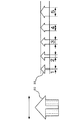
図19に示すように、表示部4に示される表示画像70には、フレームを予め定められた複数の中領域71と、中領域71に算出される一又は複数の代表的な方向の数量72として1がそれぞれ設定されている。この中領域71は、上述したように所定の数の前記小領域を一つの領域としてまとめたものであり、例えば、図18に示す小領域61と同一の大きさの領域を、4つまとめた大きさ示すものである(即ち、中領域71は、小領域61の4倍の大きさを示す)。そして、表示画像70にあっては、20の中領域が設定されている。
As shown in FIG. 19, the
なお、図19においては、中領域71以外の中領域の部材番号、及び中領域71に算出される代表的な方向の数量72以外の数量の部材番号については、説明の便宜上、その図示を省略している。
In FIG. 19, the member numbers of the middle region other than the
この前記中領域に属する小領域毎に、一又は複数の代表的な方向を算出する方法は、種々の方法を適用することができる。 Various methods can be applied to the method of calculating one or more representative directions for each of the small regions belonging to the middle region.
具体的には、例えば、ある中領域に着目し、当該中領域に属する小領域毎に最も多くのベクトル情報と近似すると判断された方向軸を抽出する。そして、小領域毎に抽出された各方向軸のうち、最も多くのベクトル情報と近似すると判断された方向軸を基準に、又は3番目に多くベクトル情報と近似すると判断された方向軸を、中領域に算出される代表的な方向の数量に応じて表示するようにしてもよい(すなわち、方向軸に近似すると判断されたベクトル情報の数量が、大きいものから順番に表示させる)。 Specifically, for example, paying attention to a certain middle region, a direction axis determined to approximate the largest amount of vector information is extracted for each small region belonging to the middle region. Then, among the direction axes extracted for each small area, the direction axis determined to approximate the most vector information or the direction axis determined to approximate the third most vector information You may make it display according to the quantity of the typical direction calculated to an area | region (Namely, the quantity of the vector information judged to approximate to a direction axis is displayed in an order from the largest).
また、中領域に属する小領域において抽出されるベクトル情報が一定の数量以下の場合には、中領域に算出される代表的な方向を表示させないようにしてもよい。 In addition, when the vector information extracted in the small area belonging to the middle area is equal to or less than a certain quantity, the representative direction calculated in the middle area may not be displayed.
また、中領域に属する小領域において抽出されるベクトル情報が、一定の数量以上の場合には、抽出されたベクトル情報の数量の比に応じて、中領域毎に、中領域に算出される代表的な方向を決定するようにしてもよい。そして、このような算出方法を適用して、移動状態算出部11が、前記中領域に属する小領域毎に、一又は複数の代表的な方向を算出した場合の算出結果について、図20を用いて説明する。
In addition, when the vector information extracted in the small area belonging to the middle area is a certain quantity or more, a representative calculated for the middle area for each middle area according to the ratio of the quantity of the extracted vector information. A specific direction may be determined. Then, by applying such a calculation method, the movement
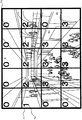
図20は、移動状態算出部11が、中領域を参照して、前記中領域に属する小領域毎に、一又は複数の代表的な方向を算出した場合の算出結果を表示した場合の表示例を示す図である。
FIG. 20 shows a display example when the movement
図20に示すように、表示部4に示される表示画像80には、中領域81に算出される代表的な方向の数量82に対応した数量の一又は複数の代表的な方向が表示されている。すなわち、表示画像80において、中領域に算出される代表的な方向の数量が0のものについては代表的な方向が表示されておらず、中領域に算出される代表的な方向の数量が1のものについては1つの代表的な方向が、中領域に算出される代表的な方向の数量が2のものについては2つの代表的な方向が、中領域に算出される代表的な方向の数量が3のものについては3つの代表的な方向が、それぞれ表示されている。また、実際の表示画像には、中領域、及び中領域に算出される代表的な方向の数量は表示されず、代表的な方向のみ表示されるように設定できる。また、上述した撮像領域の所定範囲(上述した、矩形領域20等)として、少なくとも2以上の異なる大きさの撮像領域の所定範囲を設定し、当該領域に存在するベクトル情報に含まれる方向に基づいて代表的な方向を算出させることもできる。
As shown in FIG. 20, the
ここで、2以上の異なる大きさの撮像領域の所定範囲を設定し、当該領域に存在するベクトル情報に含まれる方向に基づいて代表的な方向を算出させた場合の表示例について図21を用いて説明する。 Here, FIG. 21 is used for a display example in the case where a predetermined range of imaging regions having two or more different sizes is set and a representative direction is calculated based on a direction included in vector information existing in the region. I will explain.
図21は、2以上の異なる大きさの撮像領域の所定範囲を設定し、当該領域に存在するベクトル情報に含まれる方向に基づいて代表的な方向を算出させた場合の表示例を示す図である。 FIG. 21 is a diagram showing a display example when a predetermined range of imaging areas having two or more different sizes is set and a representative direction is calculated based on a direction included in vector information existing in the area. is there.
図21に示すように、表示部4に示される表示画像90には、商品が陳列された陳列棚91を中心に、左右方向に通路92及び通路93が表示されている。
As shown in FIG. 21, in the
そして、陳列棚91の正面に矩形領域94(異なる大きさの撮像領域の所定範囲の一例)が、通路92の入口に矩形領域95(異なる大きさの撮像領域の所定範囲の一例)が、通路93の入口に矩形領域96(異なる大きさの撮像領域の所定範囲の一例)が、それぞれ設定されている。
A rectangular area 94 (an example of a predetermined range of an imaging area having a different size) is provided in front of the
さらに、矩形領域94には矩形領域94に存在するベクトル情報に含まれる方向に基づいて算出された代表的な方向96が、矩形領域95には矩形領域95に存在するベクトル情報に含まれる方向に基づいて算出された代表的な方向97が、矩形領域96には矩形領域96に存在するベクトル情報に含まれる方向に基づいて算出された代表的な方向98が、それぞれ表示されている。
Further, a
この表示画像90に表示される代表的な方向96〜98には、例えば、陳列棚91、通路92、又は通路93に向かってくる人の人数や位置変化の大きさ、及び通過する人の人数や位置変化の大きさが示されている。
The
そして、代表的な方向96から、陳列棚91に向かってくる人の人数が多いことが示されれば、陳列棚91に陳列されている商品に興味を持つ人が多いことが把握される。
If the
また、代表的な方向96から、陳列棚91に向かってくる人の位置変化が大きいことが示されれば、少しでも早く陳列棚91に到着したいと考える人が多いことが把握される。
In addition, if it is indicated from the
また、代表的な方向96から、陳列棚91を通過する人の人数が多いことが示されれば、陳列棚91に陳列されている商品は、人気がない商品であることが把握される。
If the
さらに、代表的な方向97又は代表的な方向98から、通路92又は通路93の奥へ向かう人の人数が多いことが示されれば、通路92又は通路93の奥には、人が興味を持つ施設等が存在することが把握される。
Further, if the
なお、これらの2以上の異なる大きさの撮像領域の所定範囲は、ユーザの入力部2の操作に基づいて任意に設定することもできる。
It should be noted that the predetermined ranges of the two or more different sized imaging regions can be arbitrarily set based on the operation of the
また、撮像領域の所定範囲には、属性ラベルを設定することもできる。 An attribute label can also be set in a predetermined range of the imaging area.
この属性ラベルとは、撮像領域の所定範囲について付与される情報であり、例えば、撮像領域の所定範囲を他の範囲と識別するための識別情報や、撮像領域の所定範囲を特徴づける情報等が該当する。 This attribute label is information given for a predetermined range of the imaging region, for example, identification information for identifying the predetermined range of the imaging region from other ranges, information characterizing the predetermined range of the imaging region, etc. Applicable.
ここで、撮像領域の所定範囲に、属性ラベルを設定した場合の例を、図22を用いて説明する。 Here, an example in which an attribute label is set in a predetermined range of the imaging region will be described with reference to FIG.
図22は、2以上の撮像領域の所定範囲に、属性ラベルを設定した場合の例を示す図である。 FIG. 22 is a diagram illustrating an example when attribute labels are set in a predetermined range of two or more imaging regions.
図22に示すように、矩形領域100(2以上の撮像領域の所定範囲の一例)には、属性ラベル105が設定されている。なお、矩形領域100が示す撮像領域の所定範囲は、店舗において、低価格(価格が安い)の商品が陳列された場所を示している。そこで、属性ラベル105は、撮像領域の所定範囲を特徴づける情報として、「低価格」との情報が設定されている。
As shown in FIG. 22, an
同様に、矩形領域101〜矩形領域104には、属性ラベル106〜属性ラベル109が設定されている。
Similarly, attribute labels 106 to 109 are set in the
属性ラベル106には、中価格(例えば、ユーザが購入しやすい手頃な価格)の商品が陳列された場所を示す「中価格」との情報が、属性ラベル107には、高価格(例えば、高価な商品)の商品が陳列された場所を示す「高価格」との情報が、属性ラベル108には、新しく発売された商品が陳列された場所を示す「新製品」との情報が、属性ラベル109には、店舗の入り口又は測定開始地点を示す「トリガ」との情報がそれぞれ設定されている。
The
このように設定された属性ラベル105〜109は、例えば、表示部4に示される表示画像に表示される。この属性ラベル105〜109を見たユーザは、撮像領域の所定範囲の特徴を容易に把握することができる。
The attribute labels 105 to 109 set in this way are displayed on a display image shown on the
また、上述した例では、移動状態算出部11は、第1の座標(小領域モデル)を用いて、この代表的な方向を算出するようになっているが、第2の座標系を用いて、代表的な方向を算出するようにしてもよい。
In the example described above, the movement
ここで、第2の座標系について、図23を用いて説明する。 Here, the second coordinate system will be described with reference to FIG.
図23は、第2の座標系を示す図である。 FIG. 23 is a diagram illustrating a second coordinate system.
図23に示すように、第2の座標系Uは、原点0を中心に、原点0を示す方向を示す方向軸a〜h(本願の所定の方向から原点を示す方向軸の一例)が、原点0を中心に互いに45°(本願の所定の角度の一例)離れて8つ(本願の複数の一例)設けられている。
As shown in FIG. 23, the second coordinate system U has a direction axis a to h indicating the direction indicating the
そして、移動状態算出部11は、撮像領域の所定範囲(例えば、矩形領域20)に存在するベクトル情報に含まれる移動終了点を、第2の座標系Uの原点に仮想的に移動する。そして、移動状態算出部11は、移動させたベクトル情報に含まれる方向が、第2の座標系Uにおける何れかの方向軸a〜hの近似する範囲に該当するか判定する。
Then, the movement
このように、移動状態算出部11は、第2の座標系Uを用いて、代表的な方向を算出することによって、ベクトル情報の移動終了点を基準に近似する範囲を判定するため、装置の処理負担を軽減しつつ、撮像領域の所定範囲内へ進入する解析対象の動きを正確に解析することができる。
In this way, the movement
また、上述した例では、解析対象が示す単位時間当たりのベクトル情報を、移動開始点及び移動終了点を結ぶ直線で算出したが、移動開始点又は移動終了点を通過する近似曲線(回帰直線)で算出するようにしてもよい。 In the above-described example, the vector information per unit time indicated by the analysis target is calculated using a straight line connecting the movement start point and the movement end point. However, an approximate curve (regression line) that passes through the movement start point or the movement end point. You may make it calculate by.
ここで、解析対象が示す単位時間当たりのベクトル情報を、近似曲線で算出した場合について、図24を用いて説明する。 Here, the case where the vector information per unit time indicated by the analysis target is calculated using an approximate curve will be described with reference to FIG.
図24は、解析対象が示す単位時間当たりのベクトル情報を、近似曲線で算出した場合を示す概念図である。 FIG. 24 is a conceptual diagram illustrating a case where vector information per unit time indicated by the analysis target is calculated using an approximate curve.
まず、解析対象が示す単位時間当たりのベクトル情報を算出するに際して、単位時間を5秒として想定する。 First, when calculating the vector information per unit time indicated by the analysis target, the unit time is assumed to be 5 seconds.
図24に示すように、人H1が、位置としてV1s(x1、y1)からV5e(x6、y6)まで、5秒間で移動した場合(図の破線部で表わした矢印まで移動)を考える。この時、基準となるフレームで人H1が示す位置がV1s(x1、y1)であり、当該フレームから秒後のフレームで人H1が示す位置がV1e(x2、y2)と、さらに、1秒間隔で、人H1が示す位置がV3s(x3、y3)、V4s(x4、y4)、V5s(x5、y5)とそれぞれ特定されたものとする。なお、ある時間当たりの位置変化の移動終了点と、当該位置変化の次に算出される単位時間当たりの位置変化の移動開始点(例えば、V1eとV2s等)は同一の点を示す場合もあることは、図7を用いて既に説明したため、その説明を省略する。 As shown in FIG. 24, a case where the person H1 moves as a position from V 1s (x1, y1) to V 5e (x6, y6) in 5 seconds (moves to the arrow indicated by the broken line in the figure) is considered. . At this time, the position indicated by the person H1 in the reference frame is V 1s (x1, y1), the position indicated by the person H1 in the frame a second after the frame is V 1e (x2, y2), and 1 It is assumed that the positions indicated by the person H1 are specified as V 3s (x3, y3), V 4s (x4, y4), and V 5s (x5, y5) at second intervals, respectively. When the movement end point of the position change per certain time and the movement start point of the position change per unit time calculated after the position change (for example, V 1e and V 2s etc.) indicate the same point. Since this has already been described with reference to FIG. 7, the description thereof is omitted.
ここで、単位時間を5秒間とした場合のベクトル情報は、移動開始点V1s(x1、y1)又は、移動終了点V5e(x6、y6)の何れかを通過する、V1s(x1、y1)からV5e(x6、y6)における回帰直線を算出することによって求めることができる。 Here, the vector information when the unit time is 5 seconds passes through either the movement start point V 1s (x1, y1) or the movement end point V 5e (x6, y6), V 1s (x1, It can be obtained by calculating a regression line in V 5e (x6, y6) from y1).
この回帰直線の算出方法は公知の技術であるため、詳しい説明は省略するが、所謂、最小二乗法によって算出することができる。 Since this regression line calculation method is a known technique, a detailed description thereof is omitted, but it can be calculated by a so-called least square method.
具体的には、n個の2変数データ(x1、y1)、(x2、y2)、・・・、(xi、yi)、・・・、(xn、yn)における回帰直線は、回帰直線を式(1)とすると、式(2)及び式(3)を式(1)へ代入することにより算出される。 Specifically, n pieces of two-variable data (x 1 , y 1 ), (x 2 , y 2 ), ..., (x i , y i ), ..., (x n , y n ) The regression line is calculated by substituting Equation (2) and Equation (3) into Equation (1), where the regression line is Equation (1).
![]()
![]()

そして、こうして算出された回帰直線を、解析対象が示す単位時間当たりのベクトル情報として適用するようにしてもよい。 Then, the regression line calculated in this way may be applied as vector information per unit time indicated by the analysis target.
このように単位時間当たりのベクトル情報を回帰直線で算出することによって、単位時間当たりのベクトル情報の移動開始点から移動終了点の間における位置変化も鑑みて当該ベクトル情報が算出されるため、より正確に解析対象の動きを把握することができる。 In this way, by calculating the vector information per unit time with a regression line, the vector information is calculated in consideration of the position change between the movement start point and the movement end point of the vector information per unit time. It is possible to accurately grasp the movement of the analysis target.
なお、以上説明した実施形態は特許請求の範囲にかかる発明を限定するものではない。そして、上記実施形態の中で説明されている構成の組み合わせ全てが発明の課題解決に必須の手段であるとは限らない。 In addition, embodiment described above does not limit the invention concerning a claim. And not all the combinations of the configurations described in the above embodiment are indispensable means for solving the problems of the invention.
また、図2及び図6に示すフローチャートに対応するプログラムをフレキシブルディスク又はハードディスク等の記録媒体に記録しておき、あるいはネットワークNTを介して取得して記憶しておき、これらを汎用のパーソナルコンピュータ等に読み出して実行させることにより、当該パーソナルコンピュータ等を上記実施形態にかかる画像解析装置SSのCPUが示す動作と同様に機能させることも可能である。 Also, programs corresponding to the flowcharts shown in FIGS. 2 and 6 are recorded on a recording medium such as a flexible disk or a hard disk, or acquired and stored via the network NT, and these are stored in a general-purpose personal computer or the like. It is also possible to cause the personal computer or the like to function in the same manner as the operation indicated by the CPU of the image analysis apparatus SS according to the above-described embodiment.
以上説明したように、本実施形態においては、動画像として撮像された解析対象の動きを解析する画像解析装置SSは、撮像領域内を一定期間撮像した動画像を記憶する入力画像格納部5と、前記動画像に示される前記解析対象を検出する動体検出部6と、前記検出された解析対象が、前記撮像領域内で示す位置変化を算出し、動体IDと対応付けて位置座標記憶部8へ記憶する位置変化算出部7と、前記記憶された位置変化に基づいて、前記検出された解析対象が、前記撮像領域内で示す単位時間当たりの位置変化を、前記撮像領域内における位置及び方向を含むベクトル情報として動体ID毎に算出するベクトル情報算出部9と、前記ベクトル情報に含まれる位置に基づいて、前記撮像領域の所定範囲内に存在するベクトル情報を抽出するベクトル情報抽出部10と、前記抽出された所定範囲内に存在するベクトル情報に含まれる方向に基づいて、当該所定範囲内に存在するベクトル情報の一又は複数の代表的な方向を算出する移動状態算出部11と、前記算出された代表的な方向を、外部へ表示させる表示制御部12と、を備えるように構成したため、解析対象の動きをより正確に解析し、解析結果に対する把握性を向上させることができる。
As described above, in the present embodiment, the image analysis apparatus SS that analyzes the motion of the analysis target captured as a moving image includes the input
なお、上記実施形態においては、本願を画像解析装置SSに対して適用した場合の例を示したが、その他にも例えば、パーソナルコンピュータ又は家庭用等の電子機器等に対しても適用可能である。 In the above embodiment, an example in which the present application is applied to the image analysis apparatus SS has been described. However, the present invention can be applied to, for example, a personal computer or an electronic device for home use. .
1 画像入力部
2 入力部
3 制御部
4 表示部
5 入力画像格納部
6 動体検出部
7 位置変化算出部
8 位置座標記憶部
9 ベクトル情報算出部
10 ベクトル情報抽出部
11 移動状態算出部
12 表示制御部
13 出力フレームメモリ
SS 画像解析装置
DESCRIPTION OF
Claims (14)
撮像領域内を一定期間撮像した動画像を記憶する記憶手段と、
前記動画像に示される前記解析対象を検出する検出手段と、
前記検出された解析対象が、前記撮像領域内で示す位置変化を算出し、前記解析対象を他の解析対象と識別するための解析対象識別情報と対応付けて記憶する位置変化算出手段と、
前記記憶された位置変化に基づいて、前記検出された解析対象が前記撮像領域内で示す単位時間当たりの位置変化を、前記撮像領域内における位置及び方向を含むベクトル情報として解析対象識別情報毎に算出するベクトル情報算出手段と、
前記ベクトル情報に含まれる位置に基づいて、前記撮像領域内を所定の大きさの領域に分割する分割領域内に存在する前記ベクトル情報を、各分割領域毎に算出するベクトル情報抽出手段と、
前記分割領域毎に算出された前記ベクトル情報に含まれる方向に基づいて、前記分割領域内に存在する前記ベクトル情報の一又は複数の代表的な方向を、各分割領域毎に算出する移動状態算出手段と、
前記算出された各分割領域に対応する前記一又は複数の代表的な方向を示す矢印を、当該各分割領域について外部へ表示させる表示制御手段と、
を備え、
所定の数量の前記分割領域を一つの領域としてまとめた中領域とし、各中領域毎に算出される前記代表的な方向の数量が予め設定されており、
前記移動状態算出手段は、前記中領域毎に設定された数量に応じて、前記中領域に属する小領域毎に、前記一又は複数の代表的な方向を算出し、
前記表示制御手段は、前記算出された中領域の属する小領域毎に、前記一又は複数の代表的な方向を示す前記矢印を、当該小領域に表示させることを特徴とする画像解析装置。 An image analysis device that analyzes a motion of an analysis target captured as a moving image,
Storage means for storing a moving image captured for a certain period in the imaging area;
Detecting means for detecting the analysis target shown in the moving image;
A position change calculating means for calculating a position change indicated by the detected analysis object in the imaging region and storing it in association with analysis object identification information for identifying the analysis object from other analysis objects;
Based on the stored position change, the position change per unit time indicated by the detected analysis object in the imaging area is determined as vector information including the position and direction in the imaging area for each analysis object identification information. Vector information calculating means for calculating;
Vector information extraction means for calculating, for each divided area, the vector information existing in a divided area that divides the imaging area into areas of a predetermined size based on positions included in the vector information;
Based on the direction included in the vector information calculated for each of the divided regions, one or more representative direction of the vector information that exists in the divided region, calculating moving state for calculating the respective each divided region Means,
Display control means for displaying an arrow indicating the one or more representative directions corresponding to the calculated divided areas to the outside for the divided areas ;
Equipped with a,
A predetermined number of the divided areas are set as a middle area, and the quantity in the representative direction calculated for each middle area is set in advance.
The movement state calculation means calculates the one or more representative directions for each small area belonging to the middle area according to the quantity set for each middle area,
Wherein the display control unit, for each small area belongs areas within the calculated, the arrows indicating the one or more representative direction, an image analysis apparatus according to claim Rukoto be displayed on the small area.
前記ベクトル情報抽出手段は、前記ベクトル情報として、前記解析対象の移動開始点を算出し、前記ベクトル情報に含まれる当該移動開始点に基づいて、前記分割領域内に存在する前記ベクトル情報を抽出することを特徴とする画像解析装置。 The image analysis apparatus according to claim 1,
The vector information extraction unit calculates a movement start point of the analysis target as the vector information, and extracts the vector information existing in the divided region based on the movement start point included in the vector information. An image analysis apparatus characterized by that.
前記ベクトル情報抽出手段は、前記ベクトル情報として、前記解析対象の移動終了点を算出し、前記ベクトル情報に含まれる当該移動終了点に基づいて、前記分割領域内に存在する前記ベクトル情報を抽出することを特徴とする画像解析装置。 The image analysis apparatus according to claim 1 or 2, wherein
The vector information extraction unit calculates a movement end point of the analysis target as the vector information, and extracts the vector information existing in the divided region based on the movement end point included in the vector information. An image analysis apparatus characterized by that.
前記移動状態算出手段は、
原点を中心に所定の方向を示す複数の方向軸が当該原点を中心に所定の角度離れて設けられた第1の座標系における何れかの方向軸が示す方向と、前記算出されたベクトル情報に含まれる方向と、が近似するかを判定し、
前記ベクトル情報に含まれる方向と、近似すると判定された前記方向軸が示す方向を、前記算出されたベクトル情報の前記代表的な方向と算出することを特徴とする画像解析装置。 The image analysis apparatus according to any one of claims 1 to 3,
The movement state calculation means includes
A direction in which the plurality of axis is indicated either direction axis in the first coordinate system disposed apart a predetermined angle around the origin indicating a predetermined direction around the origin, the calculated issued vector information And the direction included in is approximated,
Image analysis device comprising a direction included in the vector information, that the direction indicated by the axis which is determined to approximate, calculated to the representative direction of the calculated issued vector information.
前記移動状態算出手段は、
所定の方向から原点を示す複数の方向軸が当該原点を中心に所定の角度離れて設けられた第2の座標系における何れかの方向軸が示す方向と、前記算出されたベクトル情報に含まれる方向と、が近似するかを判定し、
前記ベクトル情報に含まれる方向と、近似すると判定された前記方向軸が示す方向を、前記算出されたベクトル情報の前記代表的な方向と算出することを特徴とする画像解析装置。 The image analysis apparatus according to any one of claims 1 to 4, wherein:
The movement state calculation means includes
The direction indicated by either axis in the second coordinate system in which a plurality of axis indicating the origin from a predetermined direction is provided apart a predetermined angle around the origin, included in the calculation out vector information The direction to be approximated, and
Image analysis device comprising a direction included in the vector information, that the direction indicated by the axis which is determined to approximate, calculated to the representative direction of the calculated issued vector information.
前記ベクトル情報抽出手段は、少なくとも2以上の前記ベクトル情報を抽出し、
前記表示制御手段は、前記算出された代表的な方向に属する前記ベクトル情報の数量に応じて、前記外部へ表示させる前記代表的な方向を示す前記矢印の表示態様を変化させることを特徴とする画像解析装置。 An image analysis apparatus according to any one of claims 1 to 5,
The vector information extraction means extracts at least two or more vector information;
The display control means changes a display mode of the arrow indicating the representative direction to be displayed to the outside according to the quantity of the vector information belonging to the calculated representative direction. Image analysis device.
前記ベクトル情報抽出手段は、少なくとも2以上の前記ベクトル情報を抽出し、
前記表示制御手段は、前記算出された代表的な方向に属する前記ベクトル情報に含まれる位置変化の大きさに応じて、前記外部へ表示させる前記代表的な方向を示す前記矢印の表示態様を変化させることを特徴とする画像解析装置。 The image analysis apparatus according to any one of claims 1 to 6,
The vector information extraction means extracts at least two or more vector information;
The display control means changes a display mode of the arrow indicating the representative direction to be displayed to the outside according to a magnitude of a position change included in the vector information belonging to the calculated representative direction. An image analysis apparatus characterized in that
前記ベクトル情報抽出手段は、少なくとも2以上の前記ベクトル情報を抽出し、
前記表示制御手段は、前記算出された代表的な方向に属する前記ベクトル情報の数量が所定の閾値以上の場合に、当該算出された代表的な方向を示す前記矢印を外部へ表示させることを特徴とする画像解析装置。 The image analysis apparatus according to any one of claims 1 to 7,
The vector information extraction means extracts at least two or more vector information;
The display control means displays the arrow indicating the calculated representative direction to the outside when the quantity of the vector information belonging to the calculated representative direction is equal to or greater than a predetermined threshold. An image analysis device.
前記ベクトル情報抽出手段は、少なくとも2以上の前記ベクトル情報を抽出し、
前記表示制御手段は、前記算出された代表的な方向に属する前記ベクトル情報の数量が最も多い代表的な方向を抽出し、当該代表的な方向を示す前記矢印を外部へ表示させることを特徴とする画像解析装置。 The image analysis apparatus according to any one of claims 1 to 8,
The vector information extraction means extracts at least two or more vector information;
The display control means extracts a representative direction having the largest quantity of the vector information belonging to the calculated representative direction, and displays the arrow indicating the representative direction to the outside. Image analysis device.
前記ベクトル情報抽出手段は、前記ベクトル情報に含まれる位置に基づいて、少なくとも2以上の異なる大きさの前記分割領域内に存在する前記ベクトル情報を、当該分割領域内毎に抽出し、
前記移動状態算出手段は、前記抽出されたベクトル情報に含まれる方向に基づいて、当該ベクトル情報の代表的な方向を前記分割領域内毎に算出することを特徴とする画像解析装置。 The image analysis apparatus according to any one of claims 1 to 9,
The vector information extracting means extracts the vector information existing in the divided areas having at least two different sizes based on the positions included in the vector information for each divided area ,
The moving state calculation unit calculates a representative direction of the vector information for each divided region based on a direction included in the extracted vector information.
前記分割領域内を任意に設定可能な入力手段をさらに備えることを特徴とする画像解析装置。 The image analysis apparatus according to any one of claims 1 to 10,
An image analysis apparatus further comprising an input unit capable of arbitrarily setting the inside of the divided area .
撮像領域内を一定期間撮像した動画像を記憶する記憶工程と、
前記動画像に示される前記解析対象を検出する検出工程と、
前記検出された解析対象が、前記撮像領域内で示す位置変化を算出し、前記解析対象を他の解析対象と識別するための解析対象識別情報と対応付けて記憶する位置変化算出工程と、
前記記憶された位置変化に基づいて、前記検出された解析対象が前記撮像領域内で示す単位時間当たりの位置変化を、前記撮像領域内における位置及び方向を含むベクトル情報として解析対象識別情報毎に算出するベクトル情報算出工程と、
前記ベクトル情報に含まれる位置に基づいて、前記撮像領域内を所定の大きさの領域に分割する分割領域内に存在する前記ベクトル情報を、各分割領域毎に算出するベクトル情報抽出工程と、
前記分割領域毎に算出された前記ベクトル情報に含まれる方向に基づいて、前記分割領域内に存在する前記ベクトル情報の一又は複数の代表的な方向を、各分割領域毎に算出する移動状態算出工程と、
前記算出された各分割領域に対応する前記一又は複数の代表的な方向を示す矢印を、当該各分割領域について外部へ表示させる表示制御工程と、
を含み、
所定の数量の前記分割領域を一つの領域としてまとめた中領域とし、各中領域毎に算出される前記代表的な方向の数量が予め設定されており、
前記移動状態算出工程においては、前記中領域毎に設定された数量に応じて、前記中領域に属する小領域毎に、前記一又は複数の代表的な方向を算出し、
前記表示制御工程においては、前記算出された中領域の属する小領域毎に、前記一又は複数の代表的な方向を示す前記矢印を、当該小領域に表示させることを特徴とする画像解析方法。 An image analysis method in an image analysis apparatus for analyzing a motion of an analysis target captured in a moving image,
A storage step of storing a moving image captured for a certain period in the imaging region;
A detection step of detecting the analysis target shown in the moving image;
A position change calculating step in which the detected analysis object calculates a position change indicated in the imaging region, and stores the analysis object in association with analysis object identification information for identifying the analysis object from other analysis objects;
Based on the stored position change, the position change per unit time indicated by the detected analysis object in the imaging area is determined as vector information including the position and direction in the imaging area for each analysis object identification information. A vector information calculation step to calculate,
A vector information extracting step for calculating, for each divided region, the vector information existing in a divided region that divides the imaging region into regions of a predetermined size based on positions included in the vector information;
Based on the direction included in the vector information calculated for each divided area, one or a plurality of representative directions of the vector information existing in the divided area are calculated for each divided area. Process,
A display control step of displaying an arrow indicating the one or more representative directions corresponding to the calculated divided areas to the outside for the divided areas;
Including
A predetermined number of the divided areas are set as a middle area, and the quantity in the representative direction calculated for each middle area is set in advance.
In the movement state calculation step, the one or more representative directions are calculated for each small area belonging to the middle area according to the quantity set for each middle area,
Wherein in the display control step, for each small area belongs areas within the calculated, the arrows indicating the one or more representative direction, an image analysis method characterized by displaying on the small area.
撮像領域内を一定期間撮像した動画像を記憶する記憶手段、
前記動画像に示される前記解析対象を検出する検出手段、
前記検出された解析対象が、前記撮像領域内で示す位置変化を算出し、前記解析対象を他の解析対象と識別するための解析対象識別情報と対応付けて記憶する位置変化算出手段、
前記記憶された位置変化に基づいて、前記検出された解析対象が前記撮像領域内で示す単位時間当たりの位置変化を、前記撮像領域内における位置及び方向を含むベクトル情報として解析対象識別情報毎に算出するベクトル情報算出手段、
前記ベクトル情報に含まれる位置に基づいて、前記撮像領域内を所定の大きさの領域に分割する分割領域内に存在する前記ベクトル情報を、各分割領域毎に算出抽出するベクトル情報抽出手段、
前記分割領域毎に算出された前記ベクトル情報に含まれる方向に基づいて、前記分割領域内に存在する前記ベクトル情報の一又は複数の代表的な方向を、各分割領域毎に算出する移動状態算出手段、
前記算出された各分割領域に対応する前記一又は複数の代表的な方向を示す矢印を、当該各分割領域について外部へ表示させる表示制御手段、
として機能させると共に、
所定の数量の前記分割領域を一つの領域としてまとめた中領域とし、各中領域毎に算出される前記代表的な方向の数量が予め設定されており、
前記移動状態算出手段として機能する前記コンピュータを、前記中領域毎に設定された数量に応じて、前記中領域に属する小領域毎に、前記一又は複数の代表的な方向を算出するように機能させ、
前記表示制御手段として機能する前記コンピュータを、前記算出された中領域の属する小領域毎に、前記一又は複数の代表的な方向を示す前記矢印を、当該小領域に表示させるように機能させることを特徴とする画像解析プログラム。 A computer included in an image analysis apparatus that analyzes the motion of an analysis target captured in a moving image,
Storage means for storing a moving image captured for a predetermined period in the imaging region;
Detecting means for detecting the analysis target shown in the moving image;
A position change calculating means for calculating a position change indicated by the detected analysis object in the imaging region and storing the analysis object in association with analysis object identification information for identifying the analysis object from other analysis objects;
Based on the stored position change, the position change per unit time indicated by the detected analysis object in the imaging area is determined as vector information including the position and direction in the imaging area for each analysis object identification information. Vector information calculating means for calculating,
Vector information extraction means for calculating and extracting, for each divided area, the vector information existing in a divided area that divides the imaging area into areas of a predetermined size based on positions included in the vector information;
Based on the direction included in the vector information calculated for each divided area, one or a plurality of representative directions of the vector information existing in the divided area are calculated for each divided area. means,
Display control means for displaying an arrow indicating the one or more representative directions corresponding to the calculated divided areas to the outside for the divided areas;
As well as
A predetermined number of the divided areas are set as a middle area, and the quantity in the representative direction calculated for each middle area is set in advance.
The computer functioning as the movement state calculating means functions to calculate the one or more representative directions for each small area belonging to the middle area according to the quantity set for each middle area. Let
Causing the computer functioning as the display control unit to function so that the arrow indicating the one or more representative directions is displayed in the small area for each small area to which the calculated middle area belongs. An image analysis program characterized by
Priority Applications (1)
| Application Number | Priority Date | Filing Date | Title |
|---|---|---|---|
| JP2011101522A JP5776312B2 (en) | 2011-04-28 | 2011-04-28 | Image analysis apparatus, image analysis method, image analysis program, and recording medium |
Applications Claiming Priority (1)
| Application Number | Priority Date | Filing Date | Title |
|---|---|---|---|
| JP2011101522A JP5776312B2 (en) | 2011-04-28 | 2011-04-28 | Image analysis apparatus, image analysis method, image analysis program, and recording medium |
Publications (2)
| Publication Number | Publication Date |
|---|---|
| JP2012234285A JP2012234285A (en) | 2012-11-29 |
| JP5776312B2 true JP5776312B2 (en) | 2015-09-09 |
Family
ID=47434567
Family Applications (1)
| Application Number | Title | Priority Date | Filing Date |
|---|---|---|---|
| JP2011101522A Expired - Fee Related JP5776312B2 (en) | 2011-04-28 | 2011-04-28 | Image analysis apparatus, image analysis method, image analysis program, and recording medium |
Country Status (1)
| Country | Link |
|---|---|
| JP (1) | JP5776312B2 (en) |
Families Citing this family (5)
| Publication number | Priority date | Publication date | Assignee | Title |
|---|---|---|---|---|
| JP6206804B2 (en) * | 2013-09-27 | 2017-10-04 | パナソニックIpマネジメント株式会社 | Mobile object tracking device, mobile object tracking system, and mobile object tracking method |
| JP6484997B2 (en) * | 2014-10-27 | 2019-03-20 | 富士ゼロックス株式会社 | Image forming apparatus |
| US10325160B2 (en) | 2015-01-14 | 2019-06-18 | Nec Corporation | Movement state estimation device, movement state estimation method and program recording medium |
| JP2020170252A (en) * | 2019-04-01 | 2020-10-15 | キヤノン株式会社 | Image processing device, image processing method, and program |
| JP2023155637A (en) * | 2022-04-11 | 2023-10-23 | 株式会社日立製作所 | Trajectory display apparatus and method |
Family Cites Families (3)
| Publication number | Priority date | Publication date | Assignee | Title |
|---|---|---|---|---|
| JPH1062442A (en) * | 1996-08-14 | 1998-03-06 | Toyota Central Res & Dev Lab Inc | Method and system for measuring distribution of three-dimensional current velocity distribution |
| JP2006085366A (en) * | 2004-09-15 | 2006-03-30 | Oki Electric Ind Co Ltd | Speed distribution analyzing device |
| JP5155110B2 (en) * | 2008-11-17 | 2013-02-27 | 株式会社日立国際電気 | Monitoring device |
-
2011
- 2011-04-28 JP JP2011101522A patent/JP5776312B2/en not_active Expired - Fee Related
Also Published As
| Publication number | Publication date |
|---|---|
| JP2012234285A (en) | 2012-11-29 |
Similar Documents
| Publication | Publication Date | Title |
|---|---|---|
| US10810438B2 (en) | Setting apparatus, output method, and non-transitory computer-readable storage medium | |
| JP5422018B2 (en) | Image processing method and image processing apparatus | |
| JP4876687B2 (en) | Attention level measuring device and attention level measuring system | |
| CN203224887U (en) | Display control device | |
| JP6109185B2 (en) | Control based on map | |
| JP4972491B2 (en) | Customer movement judgment system | |
| JP5776312B2 (en) | Image analysis apparatus, image analysis method, image analysis program, and recording medium | |
| US8472669B2 (en) | Object localization using tracked object trajectories | |
| JP5527423B2 (en) | Image processing system, image processing method, and storage medium storing image processing program | |
| US20150103178A1 (en) | Surveillance camera control device and video surveillance system | |
| CN109727275B (en) | Object detection method, device, system and computer readable storage medium | |
| CN110287891B (en) | Gesture control method and device based on human body key points and electronic equipment | |
| CN104680504B (en) | Scene-change detecting method and its device | |
| JP2008112401A (en) | Advertisement effect measurement apparatus | |
| CN110782433A (en) | Dynamic information violent parabolic detection method and device based on time sequence and storage medium | |
| CN111862341A (en) | Virtual object driving method and device, display equipment and computer storage medium | |
| US11302045B2 (en) | Image processing apparatus, image providing apparatus,control methods thereof, and medium | |
| JP5115763B2 (en) | Image processing apparatus, content distribution system, image processing method, and program | |
| CN109905660B (en) | Method, device and computer readable storage medium for searching video event | |
| CN111986229A (en) | Video target detection method, device and computer system | |
| EP3040835B1 (en) | Image navigation | |
| JP6289027B2 (en) | Person detection device and program | |
| JP2019046278A (en) | Information processor, control method, computer program, storage medium, and model creation device | |
| CN110796062B (en) | Method and device for precisely matching and displaying object frame and storage device | |
| TW201201572A (en) | Detecting device |
Legal Events
| Date | Code | Title | Description |
|---|---|---|---|
| A621 | Written request for application examination |
Free format text: JAPANESE INTERMEDIATE CODE: A621 Effective date: 20140227 |
|
| A977 | Report on retrieval |
Free format text: JAPANESE INTERMEDIATE CODE: A971007 Effective date: 20141031 |
|
| A131 | Notification of reasons for refusal |
Free format text: JAPANESE INTERMEDIATE CODE: A131 Effective date: 20141111 |
|
| A521 | Written amendment |
Free format text: JAPANESE INTERMEDIATE CODE: A523 Effective date: 20150113 |
|
| A02 | Decision of refusal |
Free format text: JAPANESE INTERMEDIATE CODE: A02 Effective date: 20150204 |
|
| A521 | Written amendment |
Free format text: JAPANESE INTERMEDIATE CODE: A523 Effective date: 20150507 |
|
| A911 | Transfer of reconsideration by examiner before appeal (zenchi) |
Free format text: JAPANESE INTERMEDIATE CODE: A911 Effective date: 20150519 |
|
| TRDD | Decision of grant or rejection written | ||
| A01 | Written decision to grant a patent or to grant a registration (utility model) |
Free format text: JAPANESE INTERMEDIATE CODE: A01 Effective date: 20150609 |
|
| A61 | First payment of annual fees (during grant procedure) |
Free format text: JAPANESE INTERMEDIATE CODE: A61 Effective date: 20150622 |
|
| R150 | Certificate of patent or registration of utility model |
Ref document number: 5776312 Country of ref document: JP Free format text: JAPANESE INTERMEDIATE CODE: R150 |
|
| LAPS | Cancellation because of no payment of annual fees |