JP5776080B2 - Circular shape characteristic measuring method, apparatus and program - Google Patents
Circular shape characteristic measuring method, apparatus and program Download PDFInfo
- Publication number
- JP5776080B2 JP5776080B2 JP2011145301A JP2011145301A JP5776080B2 JP 5776080 B2 JP5776080 B2 JP 5776080B2 JP 2011145301 A JP2011145301 A JP 2011145301A JP 2011145301 A JP2011145301 A JP 2011145301A JP 5776080 B2 JP5776080 B2 JP 5776080B2
- Authority
- JP
- Japan
- Prior art keywords
- section
- circular
- diameter
- input
- circular cross
- Prior art date
- Legal status (The legal status is an assumption and is not a legal conclusion. Google has not performed a legal analysis and makes no representation as to the accuracy of the status listed.)
- Active
Links
Images


Classifications
-
- G—PHYSICS
- G01—MEASURING; TESTING
- G01B—MEASURING LENGTH, THICKNESS OR SIMILAR LINEAR DIMENSIONS; MEASURING ANGLES; MEASURING AREAS; MEASURING IRREGULARITIES OF SURFACES OR CONTOURS
- G01B5/00—Measuring arrangements characterised by the use of mechanical techniques
- G01B5/20—Measuring arrangements characterised by the use of mechanical techniques for measuring contours or curvatures
-
- G—PHYSICS
- G01—MEASURING; TESTING
- G01B—MEASURING LENGTH, THICKNESS OR SIMILAR LINEAR DIMENSIONS; MEASURING ANGLES; MEASURING AREAS; MEASURING IRREGULARITIES OF SURFACES OR CONTOURS
- G01B21/00—Measuring arrangements or details thereof, where the measuring technique is not covered by the other groups of this subclass, unspecified or not relevant
- G01B21/10—Measuring arrangements or details thereof, where the measuring technique is not covered by the other groups of this subclass, unspecified or not relevant for measuring diameters
-
- G—PHYSICS
- G01—MEASURING; TESTING
- G01B—MEASURING LENGTH, THICKNESS OR SIMILAR LINEAR DIMENSIONS; MEASURING ANGLES; MEASURING AREAS; MEASURING IRREGULARITIES OF SURFACES OR CONTOURS
- G01B21/00—Measuring arrangements or details thereof, where the measuring technique is not covered by the other groups of this subclass, unspecified or not relevant
- G01B21/20—Measuring arrangements or details thereof, where the measuring technique is not covered by the other groups of this subclass, unspecified or not relevant for measuring contours or curvatures, e.g. determining profile
-
- G—PHYSICS
- G01—MEASURING; TESTING
- G01B—MEASURING LENGTH, THICKNESS OR SIMILAR LINEAR DIMENSIONS; MEASURING ANGLES; MEASURING AREAS; MEASURING IRREGULARITIES OF SURFACES OR CONTOURS
- G01B5/00—Measuring arrangements characterised by the use of mechanical techniques
- G01B5/08—Measuring arrangements characterised by the use of mechanical techniques for measuring diameters
-
- G—PHYSICS
- G01—MEASURING; TESTING
- G01B—MEASURING LENGTH, THICKNESS OR SIMILAR LINEAR DIMENSIONS; MEASURING ANGLES; MEASURING AREAS; MEASURING IRREGULARITIES OF SURFACES OR CONTOURS
- G01B5/00—Measuring arrangements characterised by the use of mechanical techniques
- G01B5/20—Measuring arrangements characterised by the use of mechanical techniques for measuring contours or curvatures
- G01B5/201—Measuring arrangements characterised by the use of mechanical techniques for measuring contours or curvatures for measuring roundness
-
- G—PHYSICS
- G01—MEASURING; TESTING
- G01B—MEASURING LENGTH, THICKNESS OR SIMILAR LINEAR DIMENSIONS; MEASURING ANGLES; MEASURING AREAS; MEASURING IRREGULARITIES OF SURFACES OR CONTOURS
- G01B5/00—Measuring arrangements characterised by the use of mechanical techniques
- G01B5/20—Measuring arrangements characterised by the use of mechanical techniques for measuring contours or curvatures
- G01B5/213—Measuring arrangements characterised by the use of mechanical techniques for measuring contours or curvatures for measuring radius of curvature
Landscapes
- Physics & Mathematics (AREA)
- General Physics & Mathematics (AREA)
- A Measuring Device Byusing Mechanical Method (AREA)
- Length Measuring Devices With Unspecified Measuring Means (AREA)
Description
本発明は、測定対象を測定して得られた計測データから真円度、円筒度、同心度、同軸度、円周振れ、全振れ等の円形状特性を算出する円形状特性測定方法、装置及びプログラムに関する。 The present invention relates to a circular characteristic measurement method and apparatus for calculating circular characteristics such as roundness, cylindricity, concentricity, coaxiality, circumferential runout, and total runout from measurement data obtained by measuring a measurement object. And the program.
近年、粗さセンサーや非接触センサー等の高密度かつ定ピッチサンプリングを可能とするセンサーが搭載された形状測定機が開発されている。この様な形状測定機では、微小な凹凸を検出して分解能の高い表面粗さ測定を行うことが可能である。 In recent years, shape measuring machines equipped with sensors capable of high density and constant pitch sampling such as roughness sensors and non-contact sensors have been developed. With such a shape measuring machine, it is possible to measure surface roughness with high resolution by detecting minute irregularities.
一方、真円度や円筒度などの円形状特性を測定する場合、ワーク表面の微小凹凸によるノイズを除去する為に転がり円処理やフィルタ処理が行われることがある(特許文献1)。この様な円形状特性の測定に際しては、フィルタ処理に用いるカットオフ値、転がり円処理に用いる最小d/r比及び間引き処理に用いるサンプリング点数等のパラメータを適切に設定することが望ましい。 On the other hand, when measuring circular characteristics such as roundness and cylindricity, rolling circle processing and filter processing may be performed to remove noise due to minute irregularities on the workpiece surface (Patent Document 1). When measuring such circular characteristics, it is desirable to appropriately set parameters such as a cut-off value used for filter processing, a minimum d / r ratio used for rolling circle processing, and the number of sampling points used for thinning-out processing.
しかしながら、これらのパラメータを操作者が測定現場で適切に設定することは、経験的、時間的に困難なことが多い。このため、測定条件に適したサンプリング点数が設定されず、演算処理に必要以上の時間がかかったり、適切な精度の測定値が得られないという問題がある。 However, it is often difficult empirically and temporally for the operator to set these parameters appropriately at the measurement site. For this reason, the number of sampling points suitable for the measurement conditions is not set, and there is a problem that it takes more time than necessary for the arithmetic processing and a measurement value with appropriate accuracy cannot be obtained.
本発明はこの様な点に鑑みなされたもので、操作者の負担を増すことなく、最適な条件で精度の良い測定が可能な円形状特性測定方法、装置及びプログラムを提供することを目的としている。 The present invention has been made in view of these points, and an object of the present invention is to provide a circular characteristic measurement method, apparatus, and program capable of accurate measurement under optimum conditions without increasing the burden on the operator. Yes.
本発明に係る円形状特性測定装置は、円形断面を有する被測定物の円形断面の輪郭形状を測定し測定データを得る形状測定機と、形状測定機で得られた測定データに対して転がり円処理及びフィルタ処理を行って得られた輪郭データに基づいて円形断面の円形状特性を算出する演算処理装置とを有する。演算処理装置は、フィルタ処理のカットオフ値、最小サンプリング点数、及び転がり円処理における円形断面の径と測定子の径の比からなる3つのパラメータのうちのいずれか1つを入力パラメータとして入力する入力装置と、3つのパラメータの関係を記憶し、入力手段により入力された入力パラメータから他の2つのパラメータを決定するパラメータテーブルと、パラメータテーブルにより決定された最小サンプリング点数に基づいて測定データを間引き処理する間引き処理部とを備える。 A circular characteristic measurement apparatus according to the present invention includes a shape measuring machine that obtains measurement data by measuring the contour shape of a circular cross section of an object having a circular cross section, and a rolling circle for the measurement data obtained by the shape measuring machine. And an arithmetic processing unit that calculates circular characteristics of the circular cross section based on the contour data obtained by performing the processing and the filter processing. The arithmetic processing apparatus inputs, as an input parameter, any one of three parameters including the cutoff value of the filter process, the minimum number of sampling points, and the ratio of the diameter of the circular cross section and the diameter of the measuring element in the rolling circle process. Stores the relationship between the input device and the three parameters, determines the other two parameters from the input parameters input by the input means, and thins out the measurement data based on the minimum number of sampling points determined by the parameter table A thinning processing unit for processing.
又、本発明の一実施形態に係る円形状特性測定装置において、演算処理装置は、間引き処理された測定データに対し円形断面の径と測定子の径の比により決定された測定子の径で転がり円処理を実行する転がり円処理部と、転がり円処理部で処理された測定データに対しカットオフ値に基づいてフィルタ処理を実行するフィルタ処理部とを備える。 Further, in the circular characteristic measuring apparatus according to an embodiment of the present invention, the arithmetic processing unit has a measuring element diameter determined by a ratio of a circular section diameter and a measuring element diameter with respect to the thinned measurement data. A rolling circle processing unit that executes a rolling circle process, and a filter processing unit that performs a filtering process on the measurement data processed by the rolling circle processing unit based on a cutoff value.
本発明に係る円形状特性測定方法は、円形断面を有する被測定物の円形断面の輪郭形状を形状測定機で測定し、得られた測定データに対して、演算処理装置が転がり円処理及びフィルタ処理を行って得られた輪郭データに基づいて円形断面の円形状特性を算出する円形状特性測定方法である。フィルタ処理のカットオフ値、最小サンプリング点数、及び転がり円処理における円形断面の径と測定子の径の比からなる3つのパラメータのうちのいずれか1つを入力装置によって入力パラメータとして入力し、3つのパラメータの関係を記憶したパラメータテーブルを参照して入力手段により入力された入力パラメータから他の2つのパラメータを決定し、パラメータテーブルにより決定された最小サンプリング点数に基づいて測定データを間引き処理する。 In the circular characteristic measurement method according to the present invention, a contour shape of a circular cross section of a measurement object having a circular cross section is measured with a shape measuring machine, and an arithmetic processing unit performs rolling circle processing and filtering on the obtained measurement data. This is a circular characteristic measurement method for calculating a circular characteristic of a circular cross section based on contour data obtained by processing. Any one of three parameters consisting of a filter processing cut-off value, a minimum number of sampling points, and a ratio of the diameter of the circular cross section to the diameter of the measuring element in the rolling circle processing is input as an input parameter by the input device. The other two parameters are determined from the input parameters input by the input means with reference to the parameter table storing the relationship between the two parameters, and the measurement data is thinned based on the minimum number of sampling points determined by the parameter table.
又、本発明の一実施形態に係る円形状特性測定方法において、演算処理装置が、間引き処理された測定データに対し円形断面の径と測定子の径の比により決定された測定子の径で転がり円処理を実行し、演算処理装置が、転がり円処理部で処理された測定データに対しカットオフ値に基づいてフィルタ処理を実行する。 Further, in the circular characteristic measurement method according to one embodiment of the present invention, the arithmetic processing unit has a probe diameter determined by a ratio of the diameter of the circular cross section and the diameter of the probe with respect to the thinned measurement data. Rolling circle processing is executed, and the arithmetic processing unit executes filter processing on the measurement data processed by the rolling circle processing unit based on the cutoff value.
又、本発明の一実施形態に係る円形状特性測定方法において、演算処理装置が、入力パラメータを順次変えて、間引き処理、転がり円処理及びフィルタ処理を繰り返し実行する。 In the circular shape characteristic measuring method according to the embodiment of the present invention, the arithmetic processing device repeatedly executes the thinning process, the rolling circle process, and the filter process by sequentially changing the input parameters.
本発明に係る円形状特性測定プログラムは、円形断面を有する被測定物の円形断面の輪郭形状を形状測定機で測定し、得られた測定データに対して、円処理及びフィルタ処理を行って得られた輪郭データに基づいて円形断面の円形状特性を算出する処理をコンピュータに実行させる円形状特性測定プログラムであって、フィルタ処理のカットオフ値、最小サンプリング点数、及び転がり円処理における円形断面の径と測定子の径の比からなる3つのパラメータのうちのいずれか1つを入力装置によって入力パラメータとして入力するステップと、3つのパラメータの関係を記憶したパラメータテーブルを参照して入力手段により入力された入力パラメータから他の2つのパラメータを決定するステップと、パラメータテーブルにより決定された最小サンプリング点数に基づいて測定データを間引き処理するステップとをコンピュータに実行させる。 The circular shape characteristic measurement program according to the present invention is obtained by measuring the contour shape of a circular cross section of a measurement object having a circular cross section with a shape measuring machine, and performing circular processing and filter processing on the obtained measurement data. A circular shape characteristic measurement program for causing a computer to execute processing for calculating a circular shape characteristic of a circular cross section based on the obtained contour data, the filter processing cutoff value, the minimum number of sampling points, and the circular cross section in rolling circle processing The step of inputting any one of the three parameters comprising the ratio of the diameter and the diameter of the probe as an input parameter by the input device, and the input by referring to the parameter table storing the relationship between the three parameters The other two parameters are determined from the input parameters determined and determined by the parameter table And a step of thinning processing the measured data based on the minimum number of sampling points on the computer.
又、本発明の一実施形態に係る円形状特性測定プログラムは、間引き処理された測定データに対し円形断面の径と測定子の径の比により決定された測定子の径で転がり円処理を実行するステップと、演算処理装置が、転がり円処理部で処理された測定データに対しカットオフ値に基づいてフィルタ処理を実行するステップとをコンピュータに実行させる。 In addition, the circular characteristic measurement program according to an embodiment of the present invention performs rolling circle processing on the thinned measurement data with the diameter of the probe determined by the ratio of the diameter of the circular cross section and the diameter of the probe. And a step of causing the computer to execute a filtering process on the measurement data processed by the rolling circle processing unit based on the cutoff value.
本発明によれば、操作者の負担を増すことなく、最適な条件で精度の良い測定が可能な円形状特性測定方法、装置及びプログラムを提供することが可能となる。 According to the present invention, it is possible to provide a circular characteristic measurement method, apparatus, and program capable of performing accurate measurement under optimum conditions without increasing the burden on the operator.
[第1実施形態]
以下、添付の図面を参照してこの発明の好ましい実施の形態について説明する。
[First Embodiment]
Hereinafter, preferred embodiments of the present invention will be described with reference to the accompanying drawings.
[システム構成]
先ず、図1を参照して、本発明の一実施形態に係る円形状特性測定方法を実現する為のシステム構成について説明する。なお、ここでは、「円形状特性」として「真円度」を測定する例について説明するが、円筒度、同心円、同軸度、円周振れ、全振れ等の他の円形状特性の測定にも同様に適用可能である。図1は、この発明の一実施形態に係る真円度測定方法を実現する為のシステム構成を示す外観斜視図である。この真円度測定システムは、真円度測定機1と、演算処理装置2とから構成される。真円度測定機1は、基台3と、この基台3上に設けられて円柱状又は円筒状のワーク4を載置すると共に回転させる求心テーブル5と、この求心テーブル5に載置されたワーク4の周面の径方向変位を検出する変位検出装置6と、これらを操作するための操作部7とを備えて構成されている。
[System configuration]
First, referring to FIG. 1, a system configuration for realizing a circular characteristic measurement method according to an embodiment of the present invention will be described. Here, an example of measuring “roundness” as “circular characteristics” will be described, but other circular characteristics such as cylindricity, concentric circles, coaxiality, circumferential runout, and total runout are also measured. The same applies. FIG. 1 is an external perspective view showing a system configuration for realizing a roundness measuring method according to an embodiment of the present invention. This roundness measuring system includes a roundness measuring machine 1 and an
求心テーブル5は、円板状の載物台11を、その下側に配置された回転駆動装置12により回転駆動して、載物台11の上に載置されたワーク4を回転させるものである。回転駆動装置12の側面には、心ずれ調節用の心出しつまみ13,14及び傾斜調節用の水平出しつまみ15,16が周方向にほぼ90度の間隔で配置されており、これらのつまみ13〜16を操作することにより、手動操作で載物台11の心出し及び水平出しが行えるようになっている。
The centripetal table 5 rotates the work 4 placed on the table 11 by rotating and driving the disk-shaped table 11 by a
変位検出装置6は次のように構成されている。即ち、基台3には上方に延びるコラム21が立設されており、このコラム21にスライダ22が上下動可能に装着されている。スライダ22にはアーム23が装着されている。アーム23は水平方向に駆動され、その先端に設けられた測定子24がワーク4の外周面と接触し、且つワーク4が回転することによって、ワーク4の外周面の径方向変位が測定データとして得られるようになっている。
The
変位検出装置6で得られた測定データは、演算処理装置2に取り込まれ、ここでワーク4の測定断面(円形断面)の真円度等が求められる。演算処理装置2は、演算処理を実行するコンピュータ31、入力装置32、及び出力装置33を有する。
The measurement data obtained by the
図2は、本実施形態に係る真円度測定方法を実現する為の真円度測定システムの構成の一部を示すブロック図である。コンピュータ31は、演算部34及び記憶装置35を備えて構成されている。真円度測定機1によりワーク4を測定して得られた測定データは、演算部34に入力される。なお、測定データは、他の真円度測定機から取得されたものであっても良いし、測定済みデータを記憶する記憶装置35から読み出された計測点群であっても良い。
FIG. 2 is a block diagram showing a part of the configuration of the roundness measurement system for realizing the roundness measurement method according to the present embodiment. The
演算部34には入力装置32が接続されており、この入力装置32を介して真円度の算出の際に必要となる計算パラメータを入力する。入力する計算パラメータとしては後述するフィルタ処理部39のカットオフ値UPR(Undulations Per Rotation)、一周当たりの最小データ数(サンプリング点数)、後述する最小d/r比等が挙げられるが、本実施形態においてはカットオフ値UPRを入力パラメータとした場合の構成について説明する。
An
演算部34は、図示しないCPUが、記憶装置35に記憶された真円度算出プログラムを実行することにより、次の各機能を実現する。
The calculation unit 34 implements the following functions by a CPU (not shown) executing a roundness calculation program stored in the
すなわち、パラメータテーブル36は入力パラメータ(カットオフ値UPR)を入力して、その他のパラメータ(サンプリング点数及び最小d/r比)を出力する。間引き処理部37は、測定データに含まれている測定点からサンプリング点数分の測定点を均一に選出し、間引きデータとして出力する。転がり円処理部38は、パラメータテーブル36から出力された最小d/r比を入力し、間引きデータに対して後述する転がり円処理を行い、転がり円データを出力する。フィルタ処理部39は、カットオフ値UPRに従って転がり円データにフィルタ処理を行い、輪郭データを出力する。真円度算出部40は輪郭データを入力して真円度を算出し、出力装置33に出力する。
That is, the parameter table 36 receives input parameters (cutoff value UPR) and outputs other parameters (sampling points and minimum d / r ratio). The thinning
入力装置32としては、マウスやキーボード等、各種入力装置が使用可能である。又、出力装置33としては、ディスプレイやプリンタ等が使用可能である。
As the
[動作]
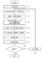
次に、本実施形態に係る真円度測定方法を実現するシステムの動作について、図3〜8を参照して詳細に説明する。図3は、本実施形態に係る真円度測定方法の処理内容を示すフローチャートである。
[Operation]
Next, the operation of the system that realizes the roundness measurement method according to the present embodiment will be described in detail with reference to FIGS. FIG. 3 is a flowchart showing the processing contents of the roundness measurement method according to the present embodiment.
本実施形態に係る真円度測定方法においては、まず入力パラメータを入力する(ステップS1)。入力パラメータの入力の際には、図4に示す様な入力用ユーザインターフェイス50を出力装置33として用いるディスプレイ上に表示して使用することが可能である。入力用ユーザインターフェイス50には、フィルタ処理を行う測定データの情報を表示する測定データ情報表示部51及びフィルタ処理部39において行われるフィルタ処理の内容を指定する各種入力部を設けることが可能である。図4に示す通り、測定データ情報表示部51には測定要素及び測定方向等の情報を表示することが可能である。
In the roundness measurement method according to the present embodiment, first, input parameters are input (step S1). When inputting input parameters, an
上述した各種入力部としては、フィルタ処理の種類を指定するフィルタ指定部52、フィルタ処理の内容を低域通過フィルタと帯域通過フィルタとから選択する通過帯域指定部53、及びカットオフ値UPRの入力を行うカットオフ値入力部54等を設けることが可能である。
As the various input units described above, the
本実施形態に係る真円度測定方法においては、高周波のノイズ成分の除去等を目的として、低域通過フィルタ処理又は帯域通過フィルタ処理を行うフィルタ処理部39を使用する。このフィルタ処理としては、図5に示す通り、CRフィルタやガウシアンフィルタ等、種々のフィルタを適用することが可能である。フィルタ指定部52においては、このフィルタ処理の内容を選択することが可能である。又、通過帯域指定部53によって帯域通過フィルタが選択されている場合には、図6に示す通りカットオフ値入力部54の表示を変化させても良い。
In the roundness measurement method according to the present embodiment, a
次に、パラメータテーブル36がカットオフ値UPRに対応した適切なサンプリング点数を求める(ステップS2)。パラメータテーブル36は、例えば図7に示すように、ISO規格やJIS規格等で提案されている対応表に従って作成された入力パラメータ(カットオフ値UPR)及び他の2つのパラメータ(サンプリング数及び最小d/r比)の関係を規定したテーブルである。又、入力パラメータとしてこの表に記載されていない値を入力された場合には、線形補完等の方法によって出力パラメータを算出することも可能である。尚、必要な場合にはパラメータテーブル36の設定を変更することも可能である。 Next, the parameter table 36 obtains an appropriate number of sampling points corresponding to the cutoff value UPR (step S2). For example, as shown in FIG. 7, the parameter table 36 includes an input parameter (cutoff value UPR) created in accordance with a correspondence table proposed in the ISO standard, JIS standard, and the like, and two other parameters (sampling number and minimum d). / R ratio) is a table defining the relationship. When a value not described in this table is input as an input parameter, the output parameter can be calculated by a method such as linear interpolation. If necessary, the setting of the parameter table 36 can be changed.
次に、間引き処理部37が、ステップS2において求められたサンプリング点数だけ測定データから測定点を選択し、間引きデータとして出力する(ステップS3)。測定点はそれぞれ角度情報と半径情報とを含んでいるが、間引き処理部37は角度データが等間隔となるように測定点を選出する。尚、間引き処理に際しては、ワーク4の形状の周波数成分が失われないように、デシメーションフィルタ(サンプリング点数をnとすると、1/2nを遮断周波数とする低域通過フィルタ)処理を行ってから間引き処理を行う。ステップS3の処理によって取り扱うデータ量が削減され、演算時間が短縮される。
Next, the thinning
次に、パラメータテーブル36が、カットオフ値UPRに対応した適切な最小d/r比を求め、転がり円処理部38が、求められた最小d/r比と、予め入力又は測定データから求めたワーク4の円形断面の直径dとから、転がり円処理に用いる測定子(スタイラスチップ)の半径rを算出する(ステップS4)。最小d/r比はサンプリング点数と同様にパラメータテーブル36の参照により求められる。
Next, the parameter table 36 obtains an appropriate minimum d / r ratio corresponding to the cutoff value UPR, and the rolling
次に、転がり円処理部38が、ステップS3において間引きされた測定データに対して転がり円処理を行う(ステップS5)。転がり円処理とは、実際に測定に使用した測定子24よりも大きい測定子を使用してワーク4を測定した場合に得られるワーク4の形状を、小さい測定子24を用いて得られた測定データから演算によって求める方法である。即ち、図8に示す様に、半径r1の測定子を用いて直径dのワーク4を測定した際に得た測定データの表面を、半径r2(>r1)の測定子を用いて倣い測定した場合の、測定子24の中心座標の軌跡を求め、転がり円データとして出力する。尚、算出された転がり円データに対して、計算の際に使用される測定子の半径rによる補正処理を施す事も可能である。
Next, the rolling
次に、フィルタ処理部39が、ステップS5において算出された転がり円データに対してフィルタ処理を行い、所定の周波数成分のみを輪郭データとして出力する(ステップS6)。上述の通り、フィルタ処理部39において行われるフィルタ処理はステップS1において設定されたカットオフ値UPRに従って行われる。
Next, the
次に、真円度算出部40が、ステップS6において算出された輪郭データから真円度を算出する(ステップS7)。真円度の算出は、輪郭データの外接円と内接円の半径を比較することによって行われる。次に、算出された真円度を出力装置33において表示・出力する(ステップS8)。
Next, the
尚、本実施形態においては入力パラメータとしてカットオフ値UPRを入力パラメータとしていたが、サンプリング点数、最小d/r比等を入力パラメータとすることも可能である。 In the present embodiment, the cut-off value UPR is used as an input parameter as an input parameter, but the number of sampling points, the minimum d / r ratio, and the like may be used as the input parameter.
本実施形態によれば、フィルタ処理のカットオフ値UPRを入力パラメータとして入力するだけで、適切なサンプリング点数と転がり円処理の測定子の半径rが求まり、これらのパラメータによって測定が実行される。従って、操作者は、カットオフ値UPRのみを入力すれば良く、操作負担は殆ど増えない。又、最適な条件での測定が行われ、処理時間が短く精度の良い測定が可能になる。 According to the present embodiment, only by inputting the filter processing cut-off value UPR as an input parameter, an appropriate number of sampling points and a radius r of a measuring element for rolling circle processing are obtained, and measurement is performed using these parameters. Therefore, the operator only has to input the cut-off value UPR, and the operation burden is hardly increased. In addition, measurement is performed under optimum conditions, and processing time is short and accurate measurement is possible.
[第2実施形態]
次に、図9及び図10を参照して、本発明の第2の実施形態について説明する。図9は、本実施形態に係る真円度測定方法を実現する為の真円度測定システムの構成の一部を示すブロック図、図10は、本実施形態に係る真円度測定方法の処理内容を示すフローチャートである。
[Second Embodiment]
Next, a second embodiment of the present invention will be described with reference to FIGS. FIG. 9 is a block diagram showing a part of the configuration of a roundness measurement system for realizing the roundness measurement method according to the present embodiment, and FIG. 10 is a process of the roundness measurement method according to the present embodiment. It is a flowchart which shows the content.
本発明の第2の実施形態は基本的には第1の実施形態と同様であるが、以下の点において異なっている。即ち、実施形態1においては入力装置1によって入力パラメータに基づく1組のパラメータに基づいて処理を行っていたが、実施形態2においては複数のパラメータの組、例えば図7に示したパラメータテーブル36に従った5通りのパラメータの組のそれぞれについて真円度を算出する点(ステップS19,S20)において異なっている。尚、予め設定した複数のパラメータの組についてのみ真円度を算出することも可能である。 The second embodiment of the present invention is basically the same as the first embodiment, but differs in the following points. That is, in the first embodiment, the input device 1 performs processing based on one set of parameters based on the input parameters. However, in the second embodiment, a plurality of parameter sets, for example, the parameter table 36 shown in FIG. The difference is that the roundness is calculated for each of the following five parameter sets (steps S19 and S20). It is also possible to calculate the roundness only for a plurality of preset parameter sets.
主要な3つのパラメータが存在する場合、測定条件は多数存在する事となるため、その全ての条件について真円度を算出すると計算量が膨大になってしまう。本実施形態においては3つのパラメータについて適切な対応関係を予め規定するパラメータテーブル36を設けることによって、複数の適切な条件についてのみ計算を行うことが可能である。 When there are three main parameters, there are a large number of measurement conditions. Therefore, calculating the roundness for all the conditions results in an enormous amount of calculation. In the present embodiment, it is possible to perform calculation only for a plurality of appropriate conditions by providing a parameter table 36 that predefines appropriate correspondences for the three parameters.
そして、複数のパラメータの組による測定結果を出力装置33に出力することにより、操作者は適切なパラメータの組を選択することができるので、操作者の測定作業負担を軽減することができる。
Then, by outputting the measurement results of a plurality of parameter sets to the
[他の実施形態]
なお、上記実施形態では、接触式の測定子24を用いた真円度測定機1により測定データが得られる例について説明したが、レーザープローブを用いた表面性状測定装置など、非接触式のセンサを用いた測定機から得られた測定データを用いることも可能であることは言うまでも無い。
[Other Embodiments]
In the above-described embodiment, the example in which the measurement data is obtained by the roundness measuring device 1 using the contact
1…真円度測定機、2…演算処理装置、3…基台、4…ワーク、5…求心テーブル、6…変位検出装置、7…操作部、11…載物台、12…回転駆動装置、13,14…心出しつまみ、15,16…水平出しつまみ、21…コラム、22…スライダ、23…アーム、24…測定子、31…コンピュータ、32…入力装置、33…出力装置、34…演算部、35…記憶装置、36…パラメータテーブル、37…間引き処理部、38…転がり円処理部、39…フィルタ処理部、40…真円度算出部。 DESCRIPTION OF SYMBOLS 1 ... Roundness measuring machine, 2 ... Arithmetic processing unit, 3 ... Base, 4 ... Work, 5 ... Centering table, 6 ... Displacement detection device, 7 ... Operation part, 11 ... Mount stage, 12 ... Rotation drive device , 13, 14 ... Centering knob, 15, 16 ... Leveling knob, 21 ... Column, 22 ... Slider, 23 ... Arm, 24 ... Measuring element, 31 ... Computer, 32 ... Input device, 33 ... Output device, 34 ... Arithmetic unit, 35 ... storage device, 36 ... parameter table, 37 ... thinning processing unit, 38 ... rolling circle processing unit, 39 ... filter processing unit, 40 ... roundness calculation unit.
Claims (7)
前記形状測定機で得られた測定データに対して転がり円処理及びフィルタ処理を行って得られた輪郭データに基づいて前記円形断面の円形状特性を算出する演算処理装置と
を有し、
前記演算処理装置は、
前記フィルタ処理のカットオフ値、最小サンプリング点数、及び転がり円処理における前記円形断面の径と測定子の径の比からなる3つのパラメータのうちのいずれか1つを入力パラメータとして入力する入力装置と、
前記3つのパラメータの関係を記憶し、前記入力装置により入力された入力パラメータから他の2つのパラメータを決定するパラメータテーブルと、
前記パラメータテーブルにより決定された最小サンプリング点数に基づいて前記測定データを間引き処理する間引き処理部と
を備えた
ことを特徴とする円形状特性測定装置。 A shape measuring machine for measuring the contour shape of the circular cross section of the object to be measured having a circular cross section to obtain measurement data; and
An arithmetic processing unit that calculates a circular shape characteristic of the circular cross section based on contour data obtained by performing rolling circle processing and filter processing on measurement data obtained by the shape measuring machine, and
The arithmetic processing unit includes:
An input device that inputs, as an input parameter, any one of three parameters including a cut-off value of the filtering process, a minimum number of sampling points, and a ratio of the diameter of the circular cross section and the diameter of the measuring element in rolling circle processing; ,
A parameter table for storing the relationship between the three parameters and determining the other two parameters from the input parameters input by the input device ;
A circular characteristic measuring apparatus comprising: a thinning processing unit that thins the measurement data based on the minimum number of sampling points determined by the parameter table.
前記間引き処理された測定データに対し前記円形断面の径と測定子の径の比により決定された測定子の径で前記転がり円処理を実行する転がり円処理部と、
前記転がり円処理部で処理された測定データに対し前記カットオフ値に基づいて前記フィルタ処理を実行するフィルタ処理部と
を備えた
ことを特徴とする請求項1記載の円形状特性測定装置。 The arithmetic processing unit includes:
A rolling circle processing unit that executes the rolling circle processing with a diameter of the measuring element determined by a ratio of a diameter of the circular cross section and a diameter of the measuring element with respect to the thinned measurement data;
The circular shape characteristic measuring apparatus according to claim 1, further comprising: a filter processing unit that performs the filtering process on the measurement data processed by the rolling circle processing unit based on the cutoff value.
前記演算処理装置は、
前記フィルタ処理のカットオフ値、最小サンプリング点数、及び転がり円処理における前記円形断面の径と測定子の径の比からなる3つのパラメータのうちのいずれか1つの入力を入力装置から受け付けて入力パラメータとし、
前記3つのパラメータの関係を記憶したパラメータテーブルを参照して前記入力装置により入力された入力パラメータから他の2つのパラメータを決定し、
前記パラメータテーブルにより決定された最小サンプリング点数に基づいて前記測定データを間引き処理する
ことを特徴とする円形状特性測定方法。 The contour shape of the circular cross section of the measurement object having a circular cross section is measured with a shape measuring machine, and the obtained measurement data is converted into contour data obtained by performing a rolling circle process and a filter process on the arithmetic processing unit. A circular shape characteristic measuring method for calculating a circular shape characteristic of the circular cross section based on:
The arithmetic processing unit includes:
Input the filtering cut-off value, the minimum number of sampling points, and the diameter of the circular cross-section in a circular process rolling and one input of one of the three parameters consisting of the ratio of the diameter of the measuring element are received from the input device Parameter ,
Determining the other two parameters from the input parameters input by the input device with reference to a parameter table storing the relationship between the three parameters;
The circular characteristic measurement method, wherein the measurement data is thinned based on the minimum number of sampling points determined by the parameter table.
前記演算処理装置は、 The arithmetic processing unit includes:
前記フィルタ処理のカットオフ値、最小サンプリング点数、及び転がり円処理における前記円形断面の径と測定子の径の比からなる3つのパラメータの関係を記憶したパラメータテーブルから前記3つのパラメータの組を順次選択し、 The set of the three parameters is sequentially obtained from a parameter table storing the relationship of the three parameters including the cut-off value of the filter processing, the minimum number of sampling points, and the ratio of the diameter of the circular cross section and the diameter of the measuring element in rolling circle processing. Selected,
前記パラメータテーブルから選択された前記3つのパラメータの組に含まれる最小サンプリング点数に基づいて、前記測定データの間引き処理を繰り返し実行する Based on the minimum number of sampling points included in the set of the three parameters selected from the parameter table, the measurement data is thinned out repeatedly.
ことを特徴とする円形状特性測定方法。 A circular characteristic measurement method characterized by the above.
前記演算処理装置が、前記転がり円処理部で処理された測定データに対し前記カットオフ値に基づいて前記フィルタ処理を実行する
ことを特徴とする請求項3又は4記載の円形状特性測定方法。 The arithmetic processing unit performs the rolling circle processing with the diameter of the measuring element determined by the ratio of the diameter of the circular cross section and the diameter of the measuring element for the thinned measurement data,
The circular shape characteristic measuring method according to claim 3 or 4 , wherein the arithmetic processing unit performs the filtering process on the measurement data processed by the rolling circle processing unit based on the cutoff value.
前記フィルタ処理のカットオフ値、最小サンプリング点数、及び転がり円処理における前記円形断面の径と測定子の径の比からなる3つのパラメータのうちのいずれか1つを入力装置によって入力パラメータとして入力するステップと、
前記3つのパラメータの関係を記憶したパラメータテーブルを参照して前記入力装置により入力された入力パラメータから他の2つのパラメータを決定するステップと、
前記パラメータテーブルにより決定された最小サンプリング点数に基づいて前記測定データを間引き処理するステップと
をコンピュータに実行させる円形状特性測定プログラム。 The contour shape of the circular cross section of the object having a circular cross section is measured with a shape measuring machine, and the circular shape is obtained based on the contour data obtained by performing rolling circle processing and filter processing on the obtained measurement data. A circular characteristic measurement program for causing a computer to execute a process of calculating a circular characteristic of a cross section,
Any one of three parameters including the cut-off value of the filter process, the minimum number of sampling points, and the ratio of the diameter of the circular cross section and the diameter of the measuring element in the rolling circle process is input as an input parameter by the input device. Steps,
Determining other two parameters from input parameters input by the input device with reference to a parameter table storing the relationship between the three parameters;
A circular characteristic measurement program for causing a computer to execute a step of thinning out the measurement data based on the minimum number of sampling points determined by the parameter table.
前記転がり円処理部で処理された測定データに対し前記カットオフ値に基づいて前記フィルタ処理を実行するステップと
をコンピュータに実行させる請求項6記載の円形状特性測定プログラム。 Performing the rolling circle process with the diameter of the measuring element determined by the ratio of the diameter of the circular cross section and the diameter of the measuring element with respect to the thinned measurement data;
Circular measuring program according to claim 6, wherein to execute and executing the filtering process on the basis of relative measurement data processed in the previous SL rolling circle section in the cut-off value to the computer.
Priority Applications (3)
| Application Number | Priority Date | Filing Date | Title |
|---|---|---|---|
| JP2011145301A JP5776080B2 (en) | 2011-06-30 | 2011-06-30 | Circular shape characteristic measuring method, apparatus and program |
| US13/527,990 US9151588B2 (en) | 2011-06-30 | 2012-06-20 | Method of measuring a circular shape characteristic and circular shape characteristic measuring device and program |
| EP12004633.9A EP2541191B1 (en) | 2011-06-30 | 2012-06-20 | Method of measuring a circle shape characteristic and circular shape characteristic measuring device and program |
Applications Claiming Priority (1)
| Application Number | Priority Date | Filing Date | Title |
|---|---|---|---|
| JP2011145301A JP5776080B2 (en) | 2011-06-30 | 2011-06-30 | Circular shape characteristic measuring method, apparatus and program |
Publications (2)
| Publication Number | Publication Date |
|---|---|
| JP2013011547A JP2013011547A (en) | 2013-01-17 |
| JP5776080B2 true JP5776080B2 (en) | 2015-09-09 |
Family
ID=46851766
Family Applications (1)
| Application Number | Title | Priority Date | Filing Date |
|---|---|---|---|
| JP2011145301A Active JP5776080B2 (en) | 2011-06-30 | 2011-06-30 | Circular shape characteristic measuring method, apparatus and program |
Country Status (3)
| Country | Link |
|---|---|
| US (1) | US9151588B2 (en) |
| EP (1) | EP2541191B1 (en) |
| JP (1) | JP5776080B2 (en) |
Families Citing this family (14)
| Publication number | Priority date | Publication date | Assignee | Title |
|---|---|---|---|---|
| US8701298B2 (en) * | 2011-06-01 | 2014-04-22 | Tesa Sa | Coordinate measuring machine |
| JP6154605B2 (en) * | 2012-09-04 | 2017-06-28 | 株式会社ミツトヨ | Shape measuring apparatus and method for correcting shape measuring error |
| US9347761B2 (en) | 2013-06-06 | 2016-05-24 | Cedarflat Precision Inc. | Two-way roundness device |
| TWI476368B (en) * | 2013-12-19 | 2015-03-11 | China Steel Corp | Cylinder calculation method |
| RU2583421C1 (en) * | 2015-04-17 | 2016-05-10 | Федеральное государственное бюджетное образовательное учреждение высшего образования "Юго-Западный государственный университет" (ЮЗГУ) | Method for statistical acceptance control of large-sized cylindrical shells of rocket fuel tanks |
| JP6428667B2 (en) * | 2016-02-12 | 2018-11-28 | トヨタ自動車株式会社 | Reference plane position measurement method |
| CN106052624B (en) * | 2016-08-16 | 2019-01-22 | 苏州天准科技股份有限公司 | A kind of high-acruracy survey mechanism detected for verticality and concentricity |
| JP6784539B2 (en) | 2016-08-31 | 2020-11-11 | 株式会社ミツトヨ | Roundness measuring machine |
| JP6802854B2 (en) * | 2016-11-01 | 2020-12-23 | 株式会社Fuji | Image processing part shape data creation system and image processing part shape data creation method |
| US10845192B2 (en) * | 2017-09-13 | 2020-11-24 | Shawn Thomas Lause | Machine tool test fixture |
| IT201700117026A1 (en) * | 2017-10-17 | 2019-04-17 | T Q M Itaca Tech S R L | MEASURING DEVICE AND METHOD FOR A SPLINED AXIALSYMMETRICAL BODY |
| JP7203312B2 (en) * | 2020-04-30 | 2023-01-13 | 株式会社東京精密 | measuring device |
| CN111595230B (en) * | 2020-06-19 | 2021-11-05 | 嘉兴巨腾信息科技有限公司 | Sampling detection device for production and processing of metal rings |
| CN116718098B (en) * | 2023-08-09 | 2023-10-17 | 成都国营锦江机器厂 | Online measurement device for coaxiality of main stay bar of helicopter and application method |
Family Cites Families (7)
| Publication number | Priority date | Publication date | Assignee | Title |
|---|---|---|---|---|
| JPH07280540A (en) * | 1994-04-05 | 1995-10-27 | Mitsutoyo Corp | Non-contact type surface shape measuring apparatus |
| JP3501260B2 (en) | 1997-02-28 | 2004-03-02 | 株式会社東京精密 | Surface roughness shape parameter setting method and surface roughness shape measurement device |
| JP2002005649A (en) * | 2000-06-20 | 2002-01-09 | Asahi Optical Co Ltd | Apparatus and method for processing point group data and recording medium stored with point-group data processing program |
| JP4782990B2 (en) * | 2004-05-31 | 2011-09-28 | 株式会社ミツトヨ | Surface scanning measuring device, surface scanning measuring method, surface scanning measuring program, and recording medium |
| JP4891629B2 (en) * | 2006-02-22 | 2012-03-07 | 株式会社ミツトヨ | Surface texture measuring machine, shape analysis program and recording medium |
| JP2008261801A (en) * | 2007-04-13 | 2008-10-30 | Nitto Seiko Co Ltd | Thread inspection apparatus |
| JP5043629B2 (en) * | 2007-12-17 | 2012-10-10 | オリンパス株式会社 | Laser scanning microscope and measuring method of surface shape thereof |
-
2011
- 2011-06-30 JP JP2011145301A patent/JP5776080B2/en active Active
-
2012
- 2012-06-20 EP EP12004633.9A patent/EP2541191B1/en active Active
- 2012-06-20 US US13/527,990 patent/US9151588B2/en active Active
Also Published As
| Publication number | Publication date |
|---|---|
| JP2013011547A (en) | 2013-01-17 |
| US20130006579A1 (en) | 2013-01-03 |
| US9151588B2 (en) | 2015-10-06 |
| EP2541191A1 (en) | 2013-01-02 |
| EP2541191B1 (en) | 2014-09-17 |
Similar Documents
| Publication | Publication Date | Title |
|---|---|---|
| JP5776080B2 (en) | Circular shape characteristic measuring method, apparatus and program | |
| JP5337955B2 (en) | Shape measuring apparatus, shape measuring method, and program | |
| JPH10507268A (en) | Roundness measurement | |
| JP2008292199A (en) | Device, method, and program for measuring roundness | |
| EP2542853B1 (en) | Surface measurement instrument and calibration thereof | |
| JP2008286535A (en) | Apparatus, method and program for measuring roundness | |
| JP2020030199A (en) | Method for analyzing surface waviness | |
| EP3746742A1 (en) | Method and apparatus for measuring surface finish of a workpiece | |
| JP6147998B2 (en) | Surface texture measuring device, surface texture measuring method and program | |
| JP5939477B1 (en) | Shape measuring device | |
| JP6250124B2 (en) | Shape measuring apparatus and shape measuring method | |
| JP5939476B1 (en) | Shape measuring device | |
| JP2001091244A (en) | Roundness measuring method and device | |
| JP6048608B2 (en) | Shape measuring device | |
| WO2016158530A1 (en) | Shape measurement device | |
| JP4088501B2 (en) | Evaluation method of measurement data | |
| CN109297691B (en) | Detection equipment and method for parameters of smoke machine | |
| KR20170092534A (en) | Method for orienting tube components | |
| JP2004195626A (en) | Lapping device and lapping method | |
| JP7392254B2 (en) | Surface texture measurement method and surface texture measurement device | |
| JP5230803B2 (en) | Workpiece measuring method, electric discharge machining method, and electric discharge machining apparatus | |
| JP2009069067A (en) | Shape analyzer and shape analyzing program | |
| JP4705815B2 (en) | Data processing apparatus, data processing method, and data processing program | |
| JP2974483B2 (en) | Method and apparatus for measuring circular motion accuracy of machine |
Legal Events
| Date | Code | Title | Description |
|---|---|---|---|
| A621 | Written request for application examination |
Free format text: JAPANESE INTERMEDIATE CODE: A621 Effective date: 20140509 |
|
| A977 | Report on retrieval |
Free format text: JAPANESE INTERMEDIATE CODE: A971007 Effective date: 20141218 |
|
| A131 | Notification of reasons for refusal |
Free format text: JAPANESE INTERMEDIATE CODE: A131 Effective date: 20150106 |
|
| A521 | Written amendment |
Free format text: JAPANESE INTERMEDIATE CODE: A523 Effective date: 20150129 |
|
| TRDD | Decision of grant or rejection written | ||
| A01 | Written decision to grant a patent or to grant a registration (utility model) |
Free format text: JAPANESE INTERMEDIATE CODE: A01 Effective date: 20150609 |
|
| A61 | First payment of annual fees (during grant procedure) |
Free format text: JAPANESE INTERMEDIATE CODE: A61 Effective date: 20150609 |
|
| R150 | Certificate of patent or registration of utility model |
Ref document number: 5776080 Country of ref document: JP Free format text: JAPANESE INTERMEDIATE CODE: R150 |
|
| R250 | Receipt of annual fees |
Free format text: JAPANESE INTERMEDIATE CODE: R250 |
|
| R250 | Receipt of annual fees |
Free format text: JAPANESE INTERMEDIATE CODE: R250 |