JP5775797B2 - Polishing apparatus and method - Google Patents
Polishing apparatus and method Download PDFInfo
- Publication number
- JP5775797B2 JP5775797B2 JP2011245482A JP2011245482A JP5775797B2 JP 5775797 B2 JP5775797 B2 JP 5775797B2 JP 2011245482 A JP2011245482 A JP 2011245482A JP 2011245482 A JP2011245482 A JP 2011245482A JP 5775797 B2 JP5775797 B2 JP 5775797B2
- Authority
- JP
- Japan
- Prior art keywords
- polishing
- gas
- polishing pad
- pad
- gas injection
- Prior art date
- Legal status (The legal status is an assumption and is not a legal conclusion. Google has not performed a legal analysis and makes no representation as to the accuracy of the status listed.)
- Active
Links
Images


Description
本発明は、半導体ウエハ等の基板を研磨テーブル上の研磨パッドに押圧し、基板の被研磨面と研磨パッドの相対運動により基板の被研磨面を研磨する研磨装置および方法に係り、特に研磨パッドに気体を吹き付けて研磨パッドの表面(研磨面)の温度を制御することができる研磨装置および方法に関するものである。 The present invention relates to a polishing apparatus and method for pressing a substrate such as a semiconductor wafer against a polishing pad on a polishing table and polishing the surface to be polished by relative movement of the surface to be polished and the polishing pad. The present invention relates to a polishing apparatus and method capable of controlling the temperature of the surface (polishing surface) of a polishing pad by blowing gas onto the surface.
近年、半導体デバイスの高集積化・高密度化に伴い、回路の配線がますます微細化し、多層配線の層数も増加している。回路の微細化を図りながら多層配線を実現しようとすると、下側の層の表面凹凸を踏襲しながら段差がより大きくなるので、配線層数が増加するに従って、薄膜形成における段差形状に対する膜被覆性(ステップカバレッジ)が悪くなる。したがって、多層配線にするためには、このステップカバレッジを改善し、然るべき過程で平坦化処理しなければならない。また光リソグラフィの微細化とともに焦点深度が浅くなるため、半導体デバイスの表面の凹凸段差が焦点深度以下に収まるように半導体デバイス表面を平坦化処理する必要がある。 In recent years, with higher integration and higher density of semiconductor devices, circuit wiring has become increasingly finer and the number of layers of multilayer wiring has increased. When trying to realize multilayer wiring while miniaturizing the circuit, the step becomes larger while following the surface unevenness of the lower layer, so as the number of wiring layers increases, the film coverage to the step shape in thin film formation (Step coverage) deteriorates. Therefore, in order to obtain a multi-layer wiring, it is necessary to improve the step coverage and perform a flattening process in an appropriate process. Further, since the depth of focus becomes shallower as the optical lithography becomes finer, it is necessary to planarize the surface of the semiconductor device so that the uneven steps on the surface of the semiconductor device are kept below the depth of focus.
従って、半導体デバイスの製造工程においては、半導体デバイス表面の平坦化技術がますます重要になっている。この平坦化技術のうち、最も重要な技術は、化学的機械研磨(CMP(Chemical Mechanical Polishing))である。この化学的機械的研磨は、研磨装置を用いて、シリカ(SiO2)やセリア(CeO2)等の砥粒を含んだ研磨液(スラリー)を研磨パッドに供給しつつ半導体ウエハなどの基板を研磨パッドに摺接させて研磨を行うものである。 Accordingly, in the semiconductor device manufacturing process, a planarization technique for the surface of the semiconductor device is becoming increasingly important. Among the planarization techniques, the most important technique is chemical mechanical polishing (CMP). In this chemical mechanical polishing, a polishing apparatus (slurry) containing abrasive grains such as silica (SiO 2 ) and ceria (CeO 2 ) is supplied to a polishing pad using a polishing apparatus, and a substrate such as a semiconductor wafer is removed. Polishing is carried out by being brought into sliding contact with the polishing pad.
上述したCMPプロセスを行う研磨装置は、研磨パッドを有する研磨テーブルと、半導体ウエハ(基板)を保持するためのトップリング又は研磨ヘッド等と称される基板保持装置とを備えている。このような研磨装置を用いて半導体ウエハ(基板)の研磨を行う場合には、基板保持装置により半導体ウエハを保持しつつ、研磨液供給ノズルから研磨液(スラリー)を研磨パッドに供給し、半導体ウエハを研磨パッドの表面(研磨面)に対して所定の圧力で押圧する。このとき、研磨テーブルと基板保持装置とを回転させることにより半導体ウエハが研磨面に摺接し、半導体ウエハの表面が平坦かつ鏡面に研磨される。 A polishing apparatus that performs the above-described CMP process includes a polishing table having a polishing pad, and a substrate holding device called a top ring or a polishing head for holding a semiconductor wafer (substrate). When polishing a semiconductor wafer (substrate) using such a polishing apparatus, a polishing liquid (slurry) is supplied from a polishing liquid supply nozzle to a polishing pad while holding the semiconductor wafer by a substrate holding apparatus, and the semiconductor The wafer is pressed against the surface (polishing surface) of the polishing pad with a predetermined pressure. At this time, by rotating the polishing table and the substrate holding device, the semiconductor wafer comes into sliding contact with the polishing surface, and the surface of the semiconductor wafer is polished to a flat and mirror surface.
上述したCMPプロセスでは、ディッシングやエロージョン等の段差特性は、研磨パッドの温度への依存性が高いことが知られている。
また、研磨レートについても、研磨パッドの温度への依存性が確認されており、CMPプロセスによって最適な研磨レートをもたらす温度領域があり、研磨中に最適な研磨レートを長く得るためには最適な研磨パッドの温度を維持する必要がある。
そこで、本発明者らは、先に、特願2011−158080号(2011年7月19日出願)において、基板の研磨中に、気体噴射ノズルから研磨パッドに向けて気体を噴射することにより、研磨パッドの表面(研磨面)を冷却するようにした研磨装置を提案した。
In the above-described CMP process, it is known that step characteristics such as dishing and erosion are highly dependent on the temperature of the polishing pad.
Also, the dependency of the polishing rate on the temperature of the polishing pad has been confirmed, and there is a temperature range that provides an optimal polishing rate by the CMP process, which is optimal for obtaining a long optimal polishing rate during polishing. It is necessary to maintain the temperature of the polishing pad.
Therefore, the inventors previously injected gas from the gas injection nozzle toward the polishing pad during polishing of the substrate in Japanese Patent Application No. 2011-158080 (filed on July 19, 2011), A polishing apparatus was proposed in which the surface (polishing surface) of the polishing pad was cooled.
研磨装置は、上述したように、研磨液供給ノズルから研磨パッド上に研磨液(スラリー)を供給しつつ研磨テーブルを回転させることにより、基板を研磨するものであるため、研磨パッド上に供給されたスラリーのミストが周囲に飛散するという問題がある。また、基板の研磨後には研磨液供給ノズルから研磨パッド上に純水を供給しつつ研磨テーブルを回転させることにより、水ポリッシングを行ったり、洗浄を行ったりするため、研磨パッド上に供給された純水などのミストが周囲に飛散するという問題がある。このように研磨装置内は、スラリー、純水などのミストや水滴が飛散する環境にあり、飛散したスラリーなどのミストは研磨装置内の部品表面に付着し、乾燥すると粉となって研磨中に研磨パッドの表面に落下し、基板表面のスクラッチの発生原因となる。 As described above, the polishing apparatus polishes the substrate by rotating the polishing table while supplying the polishing liquid (slurry) from the polishing liquid supply nozzle onto the polishing pad, and is thus supplied onto the polishing pad. There is a problem that the mist of the slurry is scattered around. In addition, after polishing the substrate, the polishing table was rotated while supplying pure water from the polishing liquid supply nozzle onto the polishing pad to perform water polishing or cleaning, so that the substrate was supplied onto the polishing pad. There is a problem that mist such as pure water is scattered around. In this way, the inside of the polishing apparatus is in an environment where mist and water droplets such as slurry and pure water scatter, and the mist such as scattered slurry adheres to the surface of the parts in the polishing apparatus and becomes powder when dried. It falls on the surface of the polishing pad and causes scratches on the substrate surface.
特願2011−158080号において提案された気体噴射ノズルは、研磨パッドの上方に配置されたマニホールドに取り付けられているため、ノズルやノズル取付用の部品等の多数の部品が研磨パッドに対向して配置されている。そのため、これら多数の部品にスラリーが付着し、結果として、粉の発生、基板表面のスクラッチの発生へとつながる頻度が増えるという可能性がある。 Since the gas injection nozzle proposed in Japanese Patent Application No. 2011-158080 is attached to a manifold disposed above the polishing pad, a large number of parts such as nozzles and nozzle mounting parts face the polishing pad. Has been placed. Therefore, the slurry adheres to these many parts, and as a result, there is a possibility that the frequency leading to generation of powder and generation of scratches on the substrate surface may increase.
本発明は、上述の事情に鑑みなされたもので、半導体ウエハ等の基板の研磨中にノズルにより研磨パッドに気体を吹き付けて研磨パッドの表面(研磨面)の温度を制御することによりディッシングやエロージョン等を防止して段差特性の向上を図ることができるとともに研磨パッド上の研磨液(スラリー)が飛散してノズルやノズル取付部品等に付着する量を減らすことができる研磨装置および方法を提供することを目的とする。 The present invention has been made in view of the above circumstances, and during the polishing of a substrate such as a semiconductor wafer, a gas is blown onto the polishing pad by a nozzle to control the temperature of the surface (polishing surface) of the polishing pad, thereby allowing dishing and erosion. There are provided a polishing apparatus and method that can improve the step characteristics by reducing the amount of adhesion of the polishing liquid (slurry) on the polishing pad to the nozzles and nozzle mounting components. For the purpose.
上記目的を達成するため、本発明の研磨装置は、研磨テーブル上の研磨パッドに研磨対象の基板を押圧して基板の被研磨面を研磨する研磨装置において、研磨液を研磨パッドに供給して基板の研磨中に、研磨パッドに向けて気体を噴射する少なくとも1つの気体噴射ノズルを有し、研磨パッドに気体を吹き付けて研磨パッドの温度を調整するパッド温度調整機構と、研磨パッドに向けて液体又は気体と液体の混合流体を噴射する少なくとも1つのノズルを有し、研磨パッドに液体又は混合流体を吹き付けて研磨パッド上の異物を除去するアトマイザとを備え、前記パッド温度調整機構と前記アトマイザとは一体のユニットとして形成されていることを特徴とするものである。 In order to achieve the above object, a polishing apparatus of the present invention supplies a polishing liquid to a polishing pad in a polishing apparatus that presses a substrate to be polished against a polishing pad on a polishing table to polish the surface to be polished. A pad temperature adjusting mechanism that has at least one gas injection nozzle that injects gas toward the polishing pad during polishing of the substrate, and adjusts the temperature of the polishing pad by blowing gas to the polishing pad; An atomizer having at least one nozzle for injecting a liquid or a mixed fluid of gas and liquid and spraying the liquid or the mixed fluid on the polishing pad to remove foreign matters on the polishing pad; and the pad temperature adjusting mechanism and the atomizer Is formed as an integral unit.
本発明の研磨装置によれば、半導体ウエハ等の基板の研磨中に、少なくとも1つの気体噴射ノズルから研磨パッドに向けて気体を噴射することにより、研磨パッドの表面(研磨面)を冷却することができる。したがって、CMPプロセスに応じて研磨パッドの表面を最適な温度に制御することができ、研磨レートの向上を図ることができるとともにディッシングやエロージョンを防止して段差特性の向上を図ることができる。
また、本発明によれば、研磨パッドに気体を吹き付けて研磨パッドの温度を調整するパッド温度調整機構と研磨パッドに液体又は混合流体を吹き付けて研磨パッド上の異物を除去するアトマイザとを一体のユニットとして構成することにより、部品点数の削減を図ることができ、かつユニットの表面積を飛躍的に減らすことができ、汚れの付着を減らすことができる。なお、パッド温度調整機構とアトマイザは、個別に使用することもできるし、同時に使用することもできる。
According to the polishing apparatus of the present invention, during polishing of a substrate such as a semiconductor wafer, the surface (polishing surface) of the polishing pad is cooled by injecting gas from at least one gas injection nozzle toward the polishing pad. Can do. Therefore, the surface of the polishing pad can be controlled to an optimum temperature in accordance with the CMP process, the polishing rate can be improved, and dishing and erosion can be prevented to improve the step characteristics.
In addition, according to the present invention, the pad temperature adjusting mechanism that adjusts the temperature of the polishing pad by blowing gas to the polishing pad and the atomizer that removes the foreign matter on the polishing pad by blowing liquid or mixed fluid to the polishing pad are integrated. By configuring as a unit, the number of parts can be reduced, the surface area of the unit can be drastically reduced, and the adhesion of dirt can be reduced. The pad temperature adjusting mechanism and the atomizer can be used individually or simultaneously.
本発明の好ましい態様によれば、前記パッド温度調整機構は、前記気体噴射ノズルに気体を供給する流体供給路を備えることを特徴とする。
本発明の好ましい態様によれば、前記アトマイザは、前記ノズルに液体又は混合流体を供給する流体供給路を備えることを特徴とする。
According to a preferred aspect of the present invention, the pad temperature adjusting mechanism includes a fluid supply path that supplies gas to the gas injection nozzle.
According to a preferred aspect of the present invention, the atomizer includes a fluid supply path for supplying a liquid or a mixed fluid to the nozzle.
本発明の好ましい態様によれば、前記少なくとも1つの気体噴射ノズルの気体噴射方向は、前記研磨パッドの表面に対して垂直ではなく、前記研磨パッドの回転方向側に傾いていることを特徴とする。
本発明によれば、少なくとも1つの気体噴射ノズルの気体噴射方向を研磨パッドの回転方向側に傾けることにより、研磨パッドを高い冷却能力で冷却することができる。この理由は、傾けることにより被吹き付け面積を垂直の場合に比べて大きく確保できるためである。また、垂直に吹き付ける場合には跳ね返りによるスラリー飛散も懸念されるが、傾けることでスラリー飛散を抑えることができる。さらに、気体噴射方向を研磨パッドの回転方向側に傾けることにより、気体噴射によるスラリーの流れへの影響を低減することができる。
本発明によれば、気体噴射ノズルの気体噴射方向と研磨パッドの表面とのなす角を、例えば、30°〜50°に設定することにより、研磨パッドを高い冷却能力で冷却することができる。この理由は、被吹き付け面積が確保でき、かつ風量も効果的に作用させることができる角度範囲だからである。30°よりも小さいと、被吹き付け面積は大きくなるが、風量が低下して冷却効果が低減する。
According to a preferred aspect of the present invention, the gas injection direction of the at least one gas injection nozzle is not perpendicular to the surface of the polishing pad, but is inclined toward the rotation direction of the polishing pad. .
According to the present invention, the polishing pad can be cooled with a high cooling capacity by inclining the gas injection direction of at least one gas injection nozzle toward the rotation direction of the polishing pad. This is because the sprayed area can be secured larger by tilting than in the vertical case. In addition, when sprayed vertically, there is a concern about slurry scattering due to rebounding, but slanting can suppress slurry scattering. Furthermore, by inclining the gas injection direction toward the rotation direction of the polishing pad, the influence of the gas injection on the slurry flow can be reduced.
According to the present invention, the polishing pad can be cooled with high cooling capacity by setting the angle formed by the gas injection direction of the gas injection nozzle and the surface of the polishing pad to, for example, 30 ° to 50 °. This is because the sprayed area can be secured and the air volume can be effectively acted on. If it is smaller than 30 °, the sprayed area becomes large, but the air volume is reduced and the cooling effect is reduced.
本発明の好ましい態様によれば、前記少なくとも1つの気体噴射ノズルの直下の点を通り、研磨パッドの回転中心を中心とする同心円を描き、同心円上の前記直下の点における接線方向を研磨パッドの回転接線方向と定義すると、前記少なくとも1つの気体噴射ノズルの気体噴射方向は、前記回転接線方向に対して前記研磨パッドの回転中心側に傾いていることを特徴とする。
本発明によれば、少なくとも1つの気体噴射ノズルの気体噴射方向を前記回転接線方向に対して研磨パッドの回転中心側に傾けることにより、研磨パッドを高い冷却能力で冷却することができる。この理由は、研磨パッド上の基板研磨領域はドーナツ状(円環状)であり、このドーナツ状領域に沿って気体を噴射できるように、回転接線方向よりも研磨パッドの回転中心側にノズルを傾けることで、基板研磨領域を効率良く冷却するためである。
本発明によれば、気体噴射ノズルの気体噴射方向の前記回転接線方向に対する角度を、例えば、15°〜35°に設定することにより、研磨パッドを高い冷却能力で冷却することができる。この理由は、基板研磨領域において被吹き付け面積の確保が可能となることと、35°以上だとスラリー滴下位置に乱れを生じさせるためである。
According to a preferred aspect of the present invention, a concentric circle passing through a point immediately below the at least one gas injection nozzle and centering on the rotation center of the polishing pad is drawn, and a tangential direction at the point immediately below the concentric circle is defined on the polishing pad. When the rotational tangential direction is defined, the gas injection direction of the at least one gas injection nozzle is inclined to the rotation center side of the polishing pad with respect to the rotational tangential direction.
According to the present invention, the polishing pad can be cooled with a high cooling capacity by inclining the gas injection direction of at least one gas injection nozzle toward the rotation center side of the polishing pad with respect to the rotational tangential direction. This is because the substrate polishing region on the polishing pad is donut-shaped (annular), and the nozzle is tilted toward the rotation center side of the polishing pad with respect to the rotation tangential direction so that gas can be injected along the donut-shaped region. This is for efficiently cooling the substrate polishing region.
According to the present invention, the polishing pad can be cooled with a high cooling capacity by setting the angle of the gas injection direction of the gas injection nozzle with respect to the rotational tangential direction to, for example, 15 ° to 35 °. This is because it becomes possible to secure the sprayed area in the substrate polishing region, and when the angle is 35 ° or more, the slurry dropping position is disturbed.
本発明の好ましい態様によれば、前記アトマイザのノズルにおける液体又は混合流体の噴射方向は前記研磨パッドの表面に対して略垂直であることを特徴とする。
本発明によれば、前記アトマイザのノズルにおける液体又は混合流体の噴射方向を前記研磨パッドの表面に対して略垂直とすることにより、液体又は混合流体が研磨パッドの表面に当たるときの衝撃力を高めることができ、高い洗浄力を発揮することができる。
According to a preferred aspect of the present invention, the jet direction of the liquid or mixed fluid in the nozzle of the atomizer is substantially perpendicular to the surface of the polishing pad.
According to the present invention, the impact force when the liquid or mixed fluid hits the surface of the polishing pad is increased by making the ejection direction of the liquid or mixed fluid in the nozzle of the atomizer substantially perpendicular to the surface of the polishing pad. And high detergency can be demonstrated.
本発明の好ましい態様によれば、前記パッド温度調整機構および前記アトマイザは、前記研磨パッドの上方を研磨パッドの外周部から中心部まで略半径方向に延びる梁状部材に設けられていることを特徴とする。
本発明によれば、梁状部材にパッド温度調整機構とアトマイザの両者が設けられているため、ユニット全体として表面積を減らすことができ、汚れの付着量を減らすことができる。細長状の部材である梁状部材内を左右に2分し、一方にパッド温度調整機構用の流体供給路と気体噴射ノズルとを設け、他方にアトマイザ用の流体供給路とノズルとを設けることにより、温度調整機構とアトマイザとを一体のユニットとして構成することができ、きわめて簡素な構造となり、ユニット全体の表面積を減らすことができる。
前記梁状部材は、研磨テーブルの外周側で固定用アームに支持され、固定用アームは研磨テーブルの外側まで延びて装置フレーム等に固定される。したがって、梁状部材を片持ち梁のように構成して研磨パッド上を研磨パッドの外周部から中心部まで延ばすことができる。
According to a preferred aspect of the present invention, the pad temperature adjusting mechanism and the atomizer are provided on a beam-like member extending substantially radially from the outer periphery to the center of the polishing pad above the polishing pad. And
According to the present invention, since both the pad temperature adjusting mechanism and the atomizer are provided on the beam-like member, the surface area of the entire unit can be reduced, and the amount of dirt attached can be reduced. The beam-like member, which is an elongated member, is divided into left and right parts, one side is provided with a fluid supply path and gas injection nozzle for the pad temperature adjustment mechanism, and the other is provided with a fluid supply path and nozzle for the atomizer Thus, the temperature adjustment mechanism and the atomizer can be configured as an integral unit, and a very simple structure can be achieved, thereby reducing the surface area of the entire unit.
The beam member is supported by a fixing arm on the outer peripheral side of the polishing table, and the fixing arm extends to the outside of the polishing table and is fixed to an apparatus frame or the like. Therefore, the beam-like member can be configured as a cantilever and can extend from the outer periphery to the center of the polishing pad on the polishing pad.
本発明の好ましい態様によれば、前記梁状部材には、前記気体噴射ノズルの気体噴射方向側に、気体噴射ノズル用カバーを設けたことを特徴とする。
本発明によれば、気体噴射ノズルの上方を覆うように気体噴射ノズル用カバーを設けたため、気体噴射ノズルから噴射された気体を拡散させずに研磨パッドに向かって流すことができ、効率よく研磨パッドを冷却することができる。
According to a preferred embodiment of the present invention, the beam-like member, the gas ejection direction of the gas injection nozzle, characterized in that a gas jet nozzle cover.
According to the present invention, due to the provision of the gas injection nozzle cover so as to cover the upper side of the gas injection nozzle, it is possible to flow a gaseous jet from the gas injection nozzle toward the polishing pad without diffusing efficiently polished The pad can be cooled.
本発明の好ましい態様によれば、前記気体噴射ノズル用カバーは、前記梁状部材から離間するほど前記研磨パッドの表面に近づくように前記研磨パッドの表面に対して傾斜していることを特徴とする。
本発明によれば、気体噴射ノズル用カバーを気体噴射ノズルの気体噴射方向に合わせて研磨パッドに次第に近づくように下方に傾斜して設けることにより、気体噴射ノズルから噴射された気体を拡散させずに研磨パッドに向かって流すことができ、効率よく研磨パッドを冷却することができる。
According to a preferred aspect of the present invention, the gas injection nozzle cover is inclined with respect to the surface of the polishing pad so as to approach the surface of the polishing pad as the distance from the beam-shaped member increases. To do.
According to the present invention, the gas spray nozzle cover is inclined downward so as to gradually approach the polishing pad in accordance with the gas spray direction of the gas spray nozzle, so that the gas sprayed from the gas spray nozzle is not diffused. Therefore, the polishing pad can be efficiently cooled.
本発明によれば、研磨テーブル上の研磨パッドに研磨対象の基板を押圧して基板の被研磨面を研磨する研磨装置において、研磨パッドに向けて気体を噴射する少なくとも1つの気体噴射ノズルを有し、研磨パッドに気体を吹き付けて研磨パッドの温度を調整するパッド温度調整機構と、研磨パッドに向けて液体又は気体と液体の混合流体を噴射する少なくとも1つのノズルを有し、研磨パッドに液体又は混合流体を吹き付けて研磨パッド上の異物を除去するアトマイザとを備え、前記パッド温度調整機構と前記アトマイザとは一体のユニットとして形成され、前記パッド温度調整機構および前記アトマイザは、前記研磨パッドの上方を研磨パッドの外周部から中心部まで略半径方向に延びる梁状部材に設けられ、前記梁状部材には、前記気体噴射ノズルの気体噴射方向側に、気体噴射ノズル用カバーを設け、前記気体噴射ノズル用カバーの内側に、前記気体噴射ノズルから噴射された気体の流れの方向を制御する少なくとも1つの気体方向調整板を設け、該気体方向調整板は前記気体噴射ノズル用カバーから前記研磨パッドに向かって延びる板状体からなることを特徴とする。
本発明によれば、気体方向調整板により気体噴射ノズルから噴射された気体の流れの方向を制御することができるため、気体を研磨パッドに沿って流すことができ、効率よく研磨パッドを冷却することができる。
According to the onset bright, the polishing apparatus presses the substrate to be polished to a polishing pad on the polishing table for polishing a surface to be polished of the substrate, at least one gas jet nozzle for jetting a gas toward the polishing pad A pad temperature adjusting mechanism that adjusts the temperature of the polishing pad by blowing gas to the polishing pad, and at least one nozzle that ejects liquid or a mixed fluid of gas and liquid toward the polishing pad. An atomizer that sprays a liquid or a mixed fluid to remove foreign matter on the polishing pad, and the pad temperature adjustment mechanism and the atomizer are formed as an integral unit, and the pad temperature adjustment mechanism and the atomizer include the polishing pad Is provided in a beam-like member extending in a substantially radial direction from the outer peripheral portion to the center portion of the polishing pad, and the beam-like member includes the gas The morphism gas jetting direction of the nozzle, the gas injection nozzle cover provided, the inside for the cover gas jet nozzle, at least one gas direction adjusting plate to control the direction of flow of the gas injected from the gas injection nozzle The gas direction adjusting plate is formed of a plate-like body extending from the gas injection nozzle cover toward the polishing pad.
According to the present invention, since the direction of the flow of the gas injected from the gas injection nozzle can be controlled by the gas direction adjusting plate, the gas can flow along the polishing pad, and the polishing pad is efficiently cooled. be able to.
本発明の好ましい態様によれば、前記少なくとも1つの気体方向調整板の直下の点を通り、研磨パッドの回転中心を中心とする同心円を描き、同心円上の前記直下の点における接線方向を研磨パッドの回転接線方向と定義すると、前記少なくとも1つの気体方向調整板は、前記回転接線方向に対して前記研磨パッドの回転中心側に傾いていることを特徴とする。
本発明によれば、気体方向調整板により、気体噴射ノズルから噴射された気体を研磨テーブルの中心側に向かって流すことができる。
本発明によれば、平板状の気体方向調整板の前記回転接線方向に対する角度を、例えば、15°〜45°に設定することにより、研磨パッドを高い冷却能力で冷却することができる。この理由は、被吹き付け面積が確保でき効率よく冷却することができるためである。45°よりも大きいと、気体方向調整板に衝突する気体の量が増え、減圧・減速され冷却能力が低減するとともに、気体方向調整板に衝突し反射した気体が研磨パッド上のスラリー膜厚やスラリー滴下位置に乱れを生じさせるためである。
According to a preferred aspect of the present invention, a concentric circle passing through a point immediately below the at least one gas direction adjusting plate and centering on the rotation center of the polishing pad is drawn, and a tangential direction at the point immediately below the concentric circle is defined as the polishing pad. The at least one gas direction adjusting plate is inclined toward the center of rotation of the polishing pad with respect to the rotational tangential direction.
According to the present invention, the gas jetted from the gas jet nozzle can be made to flow toward the center side of the polishing table by the gas direction adjusting plate.
According to the present invention, the polishing pad can be cooled with a high cooling capacity by setting the angle of the flat gas direction adjusting plate with respect to the rotational tangential direction to, for example, 15 ° to 45 °. This is because the sprayed area can be secured and cooling can be performed efficiently. If the angle is greater than 45 °, the amount of gas that collides with the gas direction adjusting plate increases, the pressure is reduced and decelerated to reduce the cooling capacity, and the reflected gas that collides with the gas direction adjusting plate reflects the slurry film thickness on the polishing pad. This is to cause disturbance at the slurry dropping position.
本発明の好ましい態様によれば、前記気体噴射ノズル用カバーの向きを調整する機構及び/又は前記気体方向調整板の向きを調整する機構を備えたことを特徴とする。
本発明によれば、研磨パッドの表面(研磨面)と気体噴射ノズルの気体噴射方向とのなす角である気体進入角度に応じて、気体噴射ノズル用カバーの傾きを最適な傾きに調整することができる。
本発明によれば、前記気体方向調整板の向きを調整する機構によって、複数の気体方向調整板の向きを連動させて調整することができるし、また複数の気体方向調整板の向きを個別に調整することもできる。
According to a preferred aspect of the present invention, there is provided a mechanism for adjusting the direction of the gas injection nozzle cover and / or a mechanism for adjusting the direction of the gas direction adjusting plate.
According to the present invention, the inclination of the cover for the gas injection nozzle is adjusted to an optimum inclination according to the gas entrance angle that is an angle formed by the surface (polishing surface) of the polishing pad and the gas injection direction of the gas injection nozzle. Can do.
According to the present invention, by the mechanism for adjusting the direction of the gas direction adjusting plate, the direction of the plurality of gas direction adjusting plates can be adjusted in conjunction with each other, and the direction of the plurality of gas direction adjusting plates can be individually adjusted. It can also be adjusted.
本発明の好ましい態様によれば、前記梁状部材には、前記気体噴射ノズル用カバーを設けた側と反対側に、アトマイザ用飛散防止カバーを設けたことを特徴とする。
本発明によれば、アトマイザにより研磨パッドを洗浄する際に、アトマイザから噴射される流体や研磨パッド上の異物が周囲に飛散することを防止できる。
According to a preferred embodiment of the present invention, the beam-like member, on the side opposite to the side provided with the gas injection nozzle cover, characterized in that a atomizer for scattering prevention cover.
ADVANTAGE OF THE INVENTION According to this invention, when wash | cleaning a polishing pad with an atomizer, it can prevent that the fluid sprayed from an atomizer and the foreign material on a polishing pad scatter around.
本発明の好ましい態様によれば、前記少なくとも1つの気体噴射ノズルから噴射される気体の流量を制御する制御弁と、前記研磨パッドの温度を検出する温度計と、前記研磨パッドの制御目標温度である設定温度と前記温度計により検出された研磨パッドの検出温度とを比較して前記制御弁の弁開度を調整することにより、前記少なくとも1つの気体噴射ノズルから噴射される気体の流量を制御するコントローラとを備えたことを特徴とする。
本発明によれば、少なくとも1つの気体噴射ノズルから噴射される気体の流量を制御弁によって制御するとともに研磨パッドの温度を温度計により検出し、研磨パッドの制御目標温度である設定温度と前記温度計により検出された研磨パッドの検出温度とを比較して前記制御弁の弁開度を調整することにより、少なくとも1つの気体噴射ノズルから噴射される気体の流量を制御することができる。したがって、CMPプロセスに応じて研磨パッドの表面を最適な温度に制御することができる。
According to a preferred aspect of the present invention, a control valve that controls a flow rate of gas injected from the at least one gas injection nozzle, a thermometer that detects a temperature of the polishing pad, and a control target temperature of the polishing pad A flow rate of gas injected from the at least one gas injection nozzle is controlled by adjusting a valve opening degree of the control valve by comparing a predetermined temperature with a detected temperature of the polishing pad detected by the thermometer. And a controller that performs the operation.
According to the present invention, the flow rate of the gas ejected from at least one gas ejection nozzle is controlled by the control valve, the temperature of the polishing pad is detected by the thermometer, and the set temperature which is the control target temperature of the polishing pad and the temperature The flow rate of the gas injected from at least one gas injection nozzle can be controlled by comparing the detected temperature of the polishing pad detected by the meter and adjusting the valve opening of the control valve. Therefore, the surface of the polishing pad can be controlled to an optimum temperature according to the CMP process.
本発明の研磨方法は、研磨テーブル上の研磨パッドに研磨液を供給しながら研磨対象の基板を研磨パッドに押圧して基板の被研磨面を研磨する研磨方法において、少なくとも1つの気体噴射ノズルから研磨パッドに向けて気体を噴射し、前記気体噴射ノズルの近傍に設けた気体方向調整板により、前記気体噴射ノズルから噴射された気体の方向を調整して気体を研磨パッドに吹きつけることを特徴とするものである。
本発明によれば、気体方向調整板により、気体噴射ノズルから噴射された気体を研磨パッドに沿って流すことができ、効率よく研磨パッドを冷却することができる。そして、気体方向調整板により気体の流れ方向を制御することにより、研磨パッド上の研磨液の流れを制御することができる。
研磨液の状況(量、濃度、生成物など)によって研磨レートや被研磨面の平坦性が変わることがあるので、気体噴射ノズルから噴射された気体の流れを気体方向調整板により制御することにより研磨パッド上の研磨液の流れもコントロールされ、研磨性能をコントロールすることができる。
The polishing method of the present invention is a polishing method for polishing a surface to be polished of a substrate by pressing a substrate to be polished against the polishing pad while supplying a polishing liquid to a polishing pad on a polishing table. A gas is jetted toward the polishing pad, and a gas direction adjusting plate provided in the vicinity of the gas jet nozzle adjusts the direction of the gas jetted from the gas jet nozzle to blow the gas onto the polishing pad. It is what.
According to the present invention, the gas direction adjusting plate can cause the gas injected from the gas injection nozzle to flow along the polishing pad, and the polishing pad can be efficiently cooled. The flow of the polishing liquid on the polishing pad can be controlled by controlling the gas flow direction with the gas direction adjusting plate.
Since the polishing rate and the flatness of the surface to be polished may vary depending on the state of the polishing liquid (amount, concentration, product, etc.), by controlling the gas flow injected from the gas injection nozzle with the gas direction adjusting plate The flow of the polishing liquid on the polishing pad is also controlled, and the polishing performance can be controlled.
本発明の好ましい態様によれば、前記気体方向調整板により前記気体噴射ノズルから噴射された気体の方向を調整することにより、前記研磨パッド上の研磨液の流れを制御することを特徴とする。
本発明によれば、気体方向調整板により気体噴射ノズルから噴射された気体の方向を調整することにより、研磨中に研磨パッド上の研磨液の乱れを緩和して研磨液の膜厚をほぼ均一にすることができる。したがって、基板の全面を均一に研磨することができる。また、気体方向調整板により気体噴射ノズルから噴射された気体の方向を調整することにより、研磨液を基板のエッジあるいは中央付近に多め(あるいは少なめ)に流すこともでき、研磨レートおよび面内均一性を制御することができる。
According to a preferred aspect of the present invention, the flow of the polishing liquid on the polishing pad is controlled by adjusting the direction of the gas injected from the gas injection nozzle by the gas direction adjusting plate.
According to the present invention, by adjusting the direction of the gas injected from the gas injection nozzle by the gas direction adjusting plate, the disturbance of the polishing liquid on the polishing pad is alleviated during polishing, and the film thickness of the polishing liquid is substantially uniform. Can be. Therefore, the entire surface of the substrate can be uniformly polished. Also, by adjusting the direction of the gas injected from the gas injection nozzle by the gas direction adjusting plate, the polishing liquid can be flown more (or less) near the edge or center of the substrate, and the polishing rate and in-plane uniformity Gender can be controlled.
本発明の好ましい態様によれば、前記気体噴射ノズルおよび前記気体方向調整板を前記研磨テーブルの回転方向においてドレッサの下流側に配置し、研磨中にドレッシングを行っている前記ドレッサの下流側で前記研磨パッド上の研磨液の流れを制御することを特徴とする。
本発明によれば、研磨中にドレッサによるドレッシング工程が入ると、研磨液の流れが邪魔され、研磨液の膜厚が乱れた状態となりがちであるが、気体方向調整板により気体噴射ノズルから噴射された気体の方向を調整することにより、ドレッサの下流側で研磨液の流れを制御し、これにより研磨液の膜厚を制御することができる。したがって、ドレッシング工程で乱れた研磨液の膜厚をなだらかにすることができ、すなわち研磨液の膜厚をほぼ均一にすることができ、基板の全面を均一に研磨できる。
According to a preferred aspect of the present invention, the gas injection nozzle and the gas direction adjusting plate are arranged on the downstream side of the dresser in the rotational direction of the polishing table, and the downstream side of the dresser performing dressing during polishing. The flow of the polishing liquid on the polishing pad is controlled.
According to the present invention, if a dressing process using a dresser is performed during polishing, the flow of the polishing liquid is obstructed and the film thickness of the polishing liquid tends to be disturbed. By adjusting the direction of the generated gas, the flow of the polishing liquid can be controlled on the downstream side of the dresser, and thereby the film thickness of the polishing liquid can be controlled. Therefore, the film thickness of the polishing liquid disturbed in the dressing process can be made smooth, that is, the film thickness of the polishing liquid can be made almost uniform, and the entire surface of the substrate can be polished uniformly.
本発明の好ましい態様によれば、前記気体方向調整板により前記気体噴射ノズルから噴射された気体の方向を調整することにより、前記研磨パッドの外周側に向かって流れる研磨液を研磨パッドの中心側に向かって流れるように制御することを特徴とする。
本発明によれば、研磨液供給ノズルから研磨パッドに供給された新しいスラリーが研磨に使用されずに研磨パッドから流れ落ちることがないように研磨パッド上に留めることができる。したがって、研磨性能の向上を図ることができるとともに研磨液の消費量を低減することができる。
According to a preferred aspect of the present invention, by adjusting the direction of the gas injected from the gas injection nozzle by the gas direction adjusting plate, the polishing liquid flowing toward the outer peripheral side of the polishing pad is allowed to flow toward the center side of the polishing pad. It controls so that it may flow toward.
According to the present invention, the new slurry supplied to the polishing pad from the polishing liquid supply nozzle can be retained on the polishing pad so as not to flow down from the polishing pad without being used for polishing. Therefore, the polishing performance can be improved and the consumption of the polishing liquid can be reduced.
本発明の好ましい態様によれば、前記気体方向調整板により前記気体噴射ノズルから噴射された気体の方向を調整することにより、研磨テーブルの回転方向において基板を保持するトップリングの下流側にあり、研磨に使用済みの古い研磨液を研磨パッドの外周側に向かって流れるように制御することを特徴とする。
本発明によれば、研磨テーブルの回転方向において基板を保持するトップリングの下流側にあり、研磨に使用済みの古い研磨液を速やかに排出することができる。したがって、古い研磨液が研磨面上に残って研磨レートや面内均一性に悪影響を与えることを防止できる。
According to a preferred aspect of the present invention, by adjusting the direction of the gas injected from the gas injection nozzle by the gas direction adjusting plate, it is downstream of the top ring that holds the substrate in the rotation direction of the polishing table, Control is performed so that the old polishing liquid used for polishing flows toward the outer peripheral side of the polishing pad.
According to the present invention, the old polishing liquid that is located downstream of the top ring that holds the substrate in the rotation direction of the polishing table and has been used for polishing can be quickly discharged. Therefore, it is possible to prevent old polishing liquid from remaining on the polishing surface and adversely affecting the polishing rate and in-plane uniformity.
本発明の好ましい態様によれば、前記研磨パッドに研磨液を供給する研磨液供給ノズルを揺動可能とし、研磨中に研磨液の供給位置を変更することを特徴とする。
本発明によれば、研磨中に研磨液の供給位置を変更することにより、研磨に最も有効な研磨パッド上の位置に必要な量の研磨液を供給することができる。
According to a preferred aspect of the present invention, the polishing liquid supply nozzle for supplying the polishing liquid to the polishing pad is made swingable, and the supply position of the polishing liquid is changed during polishing.
According to the present invention, by changing the supply position of the polishing liquid during polishing, a necessary amount of polishing liquid can be supplied to a position on the polishing pad that is most effective for polishing.
本発明は、以下に列挙する効果を奏する。
(1)研磨中に研磨パッドの表面を冷却することにより、2つの効果が期待される。
A.研磨レートが向上し、生産性が高くなると共に基板1枚当たりの研磨液(スラリー)などの消耗品コストを低減できる。
B.ディッシングやエロージョンを防止して段差特性の向上を図ることができる。
(2)研磨パッドに気体を吹き付ける位置を最適化することにより、より一層の研磨パッドの冷却効果が見込め、一層のディッシングとエロージョンの低減が見込める。
(3)研磨パッドに気体を吹き付けて研磨パッドの温度を調整するパッド温度調整機構と研磨パッドに液体又は混合流体を吹き付けて研磨パッド上の異物を除去するアトマイザとを一体のユニットとして構成することにより、3つの効果が期待される。
A.部品点数の削減を図ることができ、かつユニットの表面積を減らすことができ、汚れの付着を減らすことができる。
B.ユニットの組み付けが簡単になり、組み付けの再現性が向上する。ノズルの位置が変わってしまうと、プロセスに影響が出る可能性があるため、組み付けの再現性向上は重要である。
C.ユニットの取付けスペースが小さくなり、研磨テーブル上方の空間を有効利用することが可能になる。
(4)パッド温度調整機構に気体噴射ノズルに加えて気体の流れ方向を制御する気体方向調整板を設けたため、3つの効果が期待される。
A.研磨中に研磨パッド上の研磨液の乱れを緩和して研磨液の膜厚をほぼ均一にすることができる。
B.研磨液を基板のエッジあるいは中央付近に多め(あるいは少なめ)に流すこともでき、研磨レートおよび面内均一性を制御することができる。
C.研磨に使用済みの古いスラリーを速やかに研磨パッドから排出し、新しいスラリーが研磨パッドから流れ落ちないようにして研磨パッド上に留めることができるため、研磨性能の向上を図ることができるとともに研磨液の消費量を低減できる。
The present invention has the following effects.
(1) Two effects are expected by cooling the surface of the polishing pad during polishing.
A. The polishing rate is improved, the productivity is increased, and the cost of consumables such as a polishing liquid (slurry) per substrate can be reduced.
B. Stepping characteristics can be improved by preventing dishing and erosion.
(2) By optimizing the position where the gas is blown onto the polishing pad, a further cooling effect of the polishing pad can be expected, and further dishing and erosion can be reduced.
(3) A pad temperature adjusting mechanism that adjusts the temperature of the polishing pad by blowing gas to the polishing pad and an atomizer that sprays a liquid or mixed fluid on the polishing pad to remove foreign matters on the polishing pad are configured as an integrated unit. Therefore, three effects are expected.
A. The number of parts can be reduced, the surface area of the unit can be reduced, and the adhesion of dirt can be reduced.
B. The assembly of the unit becomes easy and the reproducibility of the assembly is improved. If the position of the nozzle changes, there is a possibility that the process will be affected, so it is important to improve the reproducibility of the assembly.
C. The unit mounting space is reduced, and the space above the polishing table can be used effectively.
(4) Since the gas temperature adjusting plate for controlling the gas flow direction is provided in the pad temperature adjusting mechanism in addition to the gas injection nozzle, three effects are expected.
A. During polishing, the disturbance of the polishing liquid on the polishing pad can be alleviated and the film thickness of the polishing liquid can be made substantially uniform.
B. A larger amount (or less) of the polishing liquid can be allowed to flow near the edge or center of the substrate, and the polishing rate and in-plane uniformity can be controlled.
C. Since the old slurry used for polishing can be quickly discharged from the polishing pad and kept on the polishing pad so that the new slurry does not flow down from the polishing pad, it is possible to improve the polishing performance and improve the polishing liquid. Consumption can be reduced.
以下、本発明に係る研磨装置および方法の実施形態について図1乃至図20を参照して詳細に説明する。なお、図1から図20において、同一または相当する構成要素には、同一の符号を付して重複した説明を省略する。 Hereinafter, embodiments of a polishing apparatus and method according to the present invention will be described in detail with reference to FIGS. 1 to 20, the same or corresponding components are denoted by the same reference numerals, and redundant description is omitted.
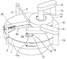
図1は、本発明に係る研磨装置の全体構成を示す模式的斜視図である。図1に示すように、研磨装置は、研磨テーブル1と、研磨対象物である半導体ウエハ等の基板Wを保持して研磨テーブル上の研磨パッドに押圧するトップリング10とを備えている。研磨テーブル1は、テーブル軸を介してその下方に配置される研磨テーブル回転モータ(図示せず)に連結されており、テーブル軸の回りに回転可能になっている。研磨テーブル1の上面には研磨パッド2が貼付されており、研磨パッド2の表面が基板Wを研磨する研磨面2aを構成している。研磨パッド2には、ロデール社製のSUBA800、IC−1000、IC−1000/SUBA400(二層クロス)等が用いられている。SUBA800は繊維をウレタン樹脂で固めた不織布である。IC−1000は硬質の発泡ポリウレタンであり、その表面に多数の微細な孔を有したパッドであり、パーフォレートパッドとも呼ばれている。研磨テーブル1の上方には研磨液供給ノズル3が設置されており、この研磨液供給ノズル3によって研磨テーブル1上の研磨パッド2に研磨液(スラリー)が供給されるようになっている。研磨液供給ノズル3の後端はシャフト4により支持されており、研磨液供給ノズル3はシャフト4を中心として揺動可能になっている。
FIG. 1 is a schematic perspective view showing the overall configuration of a polishing apparatus according to the present invention. As shown in FIG. 1, the polishing apparatus includes a polishing table 1 and a
トップリング10は、シャフト11に接続されており、シャフト11は、支持アーム12に対して上下動するようになっている。シャフト11の上下動により、支持アーム12に対してトップリング10の全体を上下動させ位置決めするようになっている。シャフト11は、研磨ヘッド回転モータ(図示せず)の駆動により回転するようになっている。シャフト11の回転により、トップリング10がシャフト11の回りに回転するようになっている。
The
トップリング10は、その下面に半導体ウエハなどの基板Wを保持できるようになっている。支持アーム12はシャフト13を中心として旋回可能に構成されており、下面に基板Wを保持したトップリング10は、支持アーム12の旋回により基板の受取位置から研磨テーブル1の上方に移動可能になっている。トップリング10は、下面に基板Wを保持して基板Wを研磨パッド2の表面(研磨面)2aに押圧する。このとき、研磨テーブル1およびトップリング10をそれぞれ回転させ、研磨テーブル1の上方に設けられた研磨液供給ノズル3から研磨パッド2上に研磨液(スラリー)を供給する。研磨液には砥粒としてシリカ(SiO2)やセリア(CeO2)を含んだ研磨液が用いられる。このように、研磨液を研磨パッド2上に供給しつつ、基板Wを研磨パッド2に押圧して基板Wと研磨パッド2とを相対移動させて基板上の絶縁膜や金属膜等を研磨する。
The
図1に示すように、研磨装置は、研磨パッド2をドレッシングするドレッシング装置15を備えている。ドレッシング装置15は、ドレッサアーム16と、ドレッサアーム16の先端に回転自在に取り付けられたドレッサ17と、ドレッサアーム16の他端に連結されるドレッサヘッド18とを備えている。ドレッサ17の下部はドレッシング部材17aにより構成され、ドレッシング部材17aは円形のドレッシング面を有しており、ドレッシング面には硬質な粒子が電着等により固定されている。この硬質な粒子としては、ダイヤモンド粒子やセラミック粒子などが挙げられる。ドレッサアーム16内には、図示しないモータが内蔵されており、このモータによってドレッサ17が回転するようになっている。ドレッサヘッド18はシャフト19により支持されている。
As shown in FIG. 1, the polishing apparatus includes a
研磨パッド2の研磨面2aをドレッシングするときは、研磨パッド2を回転させるとともに、モータによりドレッサ17を回転させ、次いで昇降機構によりドレッサ17を下降させ、ドレッサ17の下面のドレッシング部材17aを回転する研磨パッド2の研磨面に摺接させる。その状態で、ドレッサアーム16を揺動(スイング)させることにより、その先端に位置するドレッサ17は、研磨パッド2の研磨面の外周端から中心部まで横切るように移動することができる。この揺動動作により、ドレッシング部材17aは研磨パッド2の研磨面をその中心を含む全体に亘ってドレッシングすることができる。
When dressing the polishing
図1に示すように、研磨装置は、研磨パッド2に気体を吹き付けて研磨パッド2の表面(研磨面)2aの温度調整を行うパッド温度調整機構と、純水等の液体を研磨パッド2上に吹き付けて研磨パッド2上の異物を除去するアトマイザとを併設したパッド調整装置20を備えている。パッド調整装置20は、研磨パッド2の上方に配置され、研磨パッド2の表面(研磨面)2aと平行に研磨パッド2の略半径方向に延びるように配置されている。
As shown in FIG. 1, the polishing apparatus includes a pad temperature adjusting mechanism that adjusts the temperature of the surface (polishing surface) 2 a of the
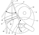
図2は、研磨テーブル1上の研磨パッド2、研磨液供給ノズル3、トップリング10、ドレッサ17およびパッド調整装置20の配置関係を示す平面図である。図2に示すように、トップリング10とドレッシング装置15とパッド調整装置20とは、研磨パッド2上の空間を研磨テーブル1の回転中心CTを中心として円周方向に3分割するように配置されている。トップリング10とパッド調整装置20とは、研磨テーブル1の回転中心CTを挟んで互いに反対側に配置されている。また、研磨液供給ノズル3はトップリング10とパッド調整装置20とに隣接して配置されており、スラリー滴下位置は研磨テーブル1の回転中心CTの近傍に設定されている。研磨液供給ノズル3はシャフト4を中心として揺動可能になっており、研磨中に研磨液(スラリー)の滴下位置を変更することができるようになっている。
FIG. 2 is a plan view showing a positional relationship among the polishing
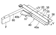
次に、パッド調整装置20の詳細構造について図3乃至図5を参照して説明する。図3は、パッド調整装置20の斜視図である。図3に示すように、パッド調整装置20は、研磨パッド2の上方において研磨パッド2の外周部から中心部まで研磨パッド2の略半径方向に延びる梁状部材からなる本体部21と、本体部21の一側部に固定された気体噴射ノズル用カバー35と、本体部21の他側部に固定された飛散防止カバー40とを備えている。また、本体部21は、研磨テーブル1の外側まで延びる固定用アーム60によって装置フレームF等に固定されるようになっている。
Next, the detailed structure of the
図4は、図3のIV−IV線断面図である。図4に示すように、本体部21は概略矩形状の断面を有しており、内部には研磨パッド2に気体を吹き付けて研磨パッド2の表面(研磨面)2aの温度調整を行うパッド温度調整機構22と、純水等の液体を研磨パッド2に吹き付けて研磨パッド2上の異物を除去するアトマイザ30とが併設されている。すなわち、パッド温度調整機構22とアトマイザ30とは1体のユニットとして形成されている。図4において本体部21の概略中心部に図示された垂直方向の一点鎖線を中心線CLとすると、中心線CLを境に右側にパッド温度調整機構22が配置され、左側にアトマイザ30が配置されている。パッド温度調整機構22は、本体部21内に形成された円形孔からなる流体供給路23を備えており、流体供給路23は圧縮空気源(図示せず)から圧縮空気を供給するようになっている。流体供給路23は本体部21の長手方向に基端部まで延びている。そして、流体供給路23の斜め下方には気体噴射ノズル24が形成されており、気体噴射ノズル24から圧縮空気が噴射されて研磨パッド2の表面(研磨面)2aに吹き付けられるようになっている。気体噴射ノズル24は流体供給路23に連通しているノズル孔から構成されており、このノズル孔は円形の貫通孔もしくは長円形の貫通孔からなっている。気体噴射ノズル24は本体部21の長手方向に沿って所定間隔をおいて複数個形成されている。
4 is a cross-sectional view taken along line IV-IV in FIG. As shown in FIG. 4, the
一方、アトマイザ30は、本体部21内の上下に形成された円形孔からなる流体供給路31,32を備えており、上の流体供給路31は純水源(図示せず)に接続され、下の流体供給路32は上の流体供給路31に連通されている。上下の流体供給路31,32は本体部21の長手方向に基端部まで延びている。そして、下の流体供給路32の下方にはノズル33が配置されている。ノズル33は本体部21の長手方向に沿って所定間隔をおいて複数個配置されている。各ノズル33は小径のノズル孔33hを有しており、ノズル孔33hは研磨パッド2の表面(研磨面)2aと概略直交するように下方に延びている。純水源から上の流体供給路31に供給された純水は、下の流体供給路32を介してノズル33に供給されるようになっている。
On the other hand, the
図4に示すように、ノズル33に純水を供給する流体供給路を上の流体供給路31と下の流体供給路32とに分け、かつ下の流体供給路32の断面積を上の流体供給路31の断面積より小さく設定している。このように、純水を上の流体供給路31から下の流体供給路32を介してノズル33に供給し、小径のノズル孔33hから純水を噴射するように構成することにより、上の流体供給路31から下の流体供給路32を介してノズル孔33hに至るまで流路断面積を徐々に狭くなるようにして流体が徐々に絞られるようにしている。これにより、流路損失をできるだけ少なくし、ノズル33から純水が研磨パッド2に効率的に吹き付けられるようにしている。
なお、上の流体供給路31に液体源から純水等の液体を供給し、下の流体供給路32に気体源から窒素(N2)ガス等の気体を供給し、液体と気体とを本体部21内に設けた混合空間で混合した後に、気液混合流体をノズル33から噴射するようにしてもよい。
As shown in FIG. 4, the fluid supply path for supplying pure water to the
A liquid such as pure water is supplied from the liquid source to the upper
図5は、図3のV−V線断面図である。図5に示すように、本体部21内には、本体部21の長手方向に延びる流体供給路23が形成されている。流体供給路23は本体部21の基端まで延び、流体供給路23の開口端には圧縮空気供給口25aを備えた継手25が固定されている。気体噴射ノズル24は本体部21の長手方向に沿って所定間隔をおいて複数個形成されている。
なお、図5では図示していないが、アトマイザ30の上下の流体供給路31,32も本体部21の長手方向に延びている。上の流体供給路31は本体部21の基端まで延び、上の流体供給路31の開口端には純水供給口34aを備えた継手34が固定されている。
また、流体供給路23,31,32を一つの共通の流体供給路とし、一つの流体供給路に気体噴射ノズル24およびノズル33を設ける構造とし、適宜流体供給源(圧縮空気源、純水源等)と、各ノズル孔の開閉を切り替える構造としてもよい。
5 is a cross-sectional view taken along line VV in FIG. As shown in FIG. 5, a
Although not shown in FIG. 5, the upper and lower
In addition, the
次に、本体部21の一側部に固定された気体噴射ノズル用カバー35および本体部21の他側部に固定された飛散防止カバー40について説明する。
図3に示すように、気体噴射ノズル用カバー35は本体部21の一側部に取り付けられており、気体噴射ノズル用カバー35は本体部21の側方において前端部から後端部まで延びている。気体噴射ノズル用カバー35の下面には複数の三角形状の気体方向調整板36が設けられている(後述する)。図4に示すように、気体噴射ノズル用カバー35は、気体噴射ノズル24のやや上方において本体部21に固定されており、気体噴射ノズル24の気体噴射方向に沿って斜め下方に延びている。すなわち、気体噴射ノズル用カバー35は、気体噴射ノズル24のやや上方の固定部35aから斜め下方に延び、固定部35aから遠くなるほど研磨パッド2の研磨面2aに近づくようになっている。ただし、気体噴射ノズル用カバー35の先端35eと研磨パッド2の研磨面2aとの間には隙間G1があり、噴射されるエア(圧縮空気)の流路を確保している。
Next, the gas
As shown in FIG. 3, the gas
また、図3および図4に示すように、飛散防止カバー40は、気体噴射ノズル用カバー35の反対側の位置において本体部21に取り付けられている。飛散防止カバー40は、本体部21の先端部から略中央部までの位置において本体部21より下方に延びる前部カバー40aと本体部21の略中央部から後端部までの位置において水平方向に概略三角形状に延びた後に下方に延びる後部カバー40bとから構成されている。ただし、飛散防止カバー40の下端40eと研磨パッド2の研磨面2aとの間には隙間G2があり、噴射される純水の流路を確保している。なお、後部カバー40bは、本体部21の先端部から後端部までの位置において水平方向に延びる形状としてもよい。
As shown in FIGS. 3 and 4, the
図6は、気体噴射ノズル用カバー35の下面に設置された気体方向調整板36を示す図である。図6に示すように、気体噴射ノズル用カバー35の下面には、複数の三角形状の気体方向調整板36が所定の間隔をおいて設けられている。各気体方向調整板36は研磨パッド2に向かって垂直方向に延びる三角形状の板状体からなっている。そして、気体方向調整板36の下端36eと気体噴射ノズル用カバー35の先端35eとは、同一面になっており、気体方向調整板36の下端36eと研磨パッド2の研磨面2aとの間には隙間G1がある。このように、気体噴射ノズル用カバー35の下面に複数の気体方向調整板36を設けることにより、気体噴射ノズル24から噴射されたエア(圧縮空気)を所定の方向に流れるように調整(制御)することができる。
FIG. 6 is a view showing the gas
図3乃至図6に示す実施形態においては、梁状部材からなる本体部21内に、流体供給路23と気体噴射ノズル24とからなるパッド温度調整機構22と、流体供給路31と流体供給路32とノズル33とからなるアトマイザ30とを設けることにより、パッド温度調整機構22とアトマイザ30とを一体のユニットとして形成している。しかしながら、流体供給路23をパイプで構成し、気体噴射ノズル24を流体供給路23に固定された別体のノズルで構成することによりパッド温度調整機構22を形成し、また流体供給路31と流体供給路32とをそれぞれパイプで構成してこれらのパイプを短管で連通させ、ノズル33を流体供給路32に固定された別体のノズルで構成することによりアトマイザ30を形成し、これらパッド温度調整機構22とアトマイザ30とをカバー内に収容することによっても、パッド温度調整機構22とアトマイザ30とを一体のユニットとして形成することができる。
In the embodiment shown in FIGS. 3 to 6, a pad
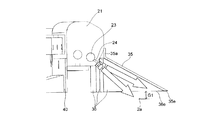
図7は、パッド調整装置20のパッド温度調整機構22およびアトマイザ30の制御機器を示す斜視図である。図7に示すように、研磨テーブル1の上面には研磨パッド2が貼付されている。研磨パッド2の上方にはトップリング10が配置されており、トップリング10は基板W(図1参照)を保持して基板Wを研磨パッド2に押圧するようになっている。パッド温度調整機構22は、圧縮空気供給ライン45によって圧縮空気源に接続されている。圧縮空気供給ライン45には圧力制御弁46が設けられており、圧縮空気源から供給された圧縮空気が圧力制御弁46を通過することで圧力および流量が制御されるようになっている。圧力制御弁46は温度コントローラ47に接続されている。圧縮空気は常温であってもよいし、所定温度に冷却してもよい。
FIG. 7 is a perspective view showing the pad
図7に示すように、研磨パッド2の上方には、研磨パッド2の表面温度を検出する放射温度計48が設置されている。放射温度計48は温度コントローラ47に接続されている。温度コントローラ47には、研磨装置の全体を制御するCMPコントローラから研磨パッド2の制御目標温度である設定温度が入力されるようになっている。また、温度コントローラ47には設定温度を直接入力することもできる。温度コントローラ47は、温度コントローラ47に入力された研磨パッド2の設定温度と放射温度計48により検出された研磨パッド2の実際の温度との差に応じてPID制御により圧力制御弁46の弁開度を調整し、気体噴射ノズル24から噴射される圧縮空気の流量を制御する。これにより、気体噴射ノズル24から研磨パッド2の研磨面2aに最適な流量の圧縮空気が吹き付けられ、研磨パッド2の研磨面2aの温度は温度コントローラ47で設定された目標温度(設定温度)に維持される。
As shown in FIG. 7, a
図7に示すように、アトマイザ30は、純水供給ライン49によって純水供給源に接続されている。純水供給ライン49には制御弁50が設けられている。CMPコントローラから制御信号が制御弁50に入力され、ノズル33から噴射される純水の流量を制御する。これにより、研磨パッド2の研磨面2aに最適な流量の純水が吹き付けられ、研磨パッド上の異物(研磨パッド滓、砥液固着物等)が除去される。なお、ノズル33から混合流体を噴射する場合には、アトマイザ30は気体源にも接続される。
As shown in FIG. 7, the
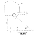
図8および図9は、パッド温度調整機構22の気体噴射ノズル24と研磨パッド2との関係を示す図であり、図8は模式的平面図であり、図9は模式的側面図である。図8および図9においては、アトマイザ30は図示を省略している。図8に示すように、パッド温度調整機構22は、本体部21の長手方向に所定間隔をおいて配置された複数の気体噴射ノズル24を備えている(図示例では8個のノズルが取り付けられている)。研磨中に、研磨パッド2は回転中心CTの回りに時計方向に回転する。図8において、パッド内側から1,2,3・・・8の昇順でノズルに番号付けを行い、例えば、3番目と6番目の2つの気体噴射ノズル24を例に挙げて説明する。すなわち、3番目と6番目の2つの気体噴射ノズル24の直下の点P1,P2を通り、CTを中心とする同心円C1,C2を描き、同心円C1,C2上の点P1,P2における接線方向を研磨パッドの回転接線方向と定義すると、気体噴射ノズル24の気体噴射方向は、研磨パッドの回転接線方向に対してパッド中心側に所定角度(θ1)だけ傾いている。気体噴射方向とは、気体噴射ノズル口から気体が扇状に広がる角度(気体噴射角)の中心線の方向をいう。3番目と6番目のノズル以外の他のノズルも同様に研磨パッドの回転接線方向に対してパッド中心側に所定角度(θ1)だけ傾いている。そして、研磨パッドの回転接線方向に対する気体噴射ノズル24の気体噴射方向の角度(θ1)は、ノズル冷却能力との関係で15°〜35°に設定されている(後述する)。なお、ここではノズルが複数ある場合を説明したが、ノズルは1つでもよい。
8 and 9 are views showing the relationship between the
また、図9に示すように、気体噴射ノズル24の気体噴射方向は、研磨パッド2の表面(研磨面)2aに対して垂直ではなく、研磨テーブル1の回転方向側に所定角度だけ傾いている。研磨パッド2の表面(研磨面)2aに対する気体噴射ノズル24の気体噴射方向の角度、すなわち、研磨パッド2の表面(研磨面)2aと気体噴射ノズル24の気体噴射方向とのなす角を気体進入角度(θ2)と定義すると、気体進入角度(θ2)は、ノズル冷却能力との関係で30°〜50°に設定されている(後述する)。ここで、気体噴射方向とは、気体噴射ノズル口から気体が扇状に広がる角度(気体噴射角)の中心線の方向をいう。
As shown in FIG. 9, the gas injection direction of the
また、図9に示すように、本体部21は上下動可能に構成されているため、本体部21の高さ(H)が可変になっており、気体噴射ノズル24の研磨パッド表面(研磨面)2aからの高さを調節することが可能になっている。なお、図8では気体噴射ノズル24の個数が8個の場合を図示したが、ノズルの個数はノズル孔をプラグ等で閉止することにより調整することが可能であり、2〜3個の場合もある。ノズルの個数は研磨パッド2を冷却するための冷却能力に応じて適宜選定される。
Further, as shown in FIG. 9, since the
図10(a)は、気体噴射ノズル24の気体噴射方向を研磨パッドの回転接線方向に対して傾けない場合(θ1=0°)と、パッド中心側に傾けた場合(θ1=15°,θ1=30°)における冷却能力を示すグラフである。図10(a)において、縦軸は、冷却無しのパッド温度とノズルを用いた冷却有りのパッド温度との差(℃)を表し、この差はノズルの冷却能力を表すものである。図10(a)に示すように、研磨パッドの回転接線方向に対する気体噴射ノズル24の気体噴射方向の角度(θ1)が大きくなるほど冷却能力が向上する傾向にある。ただし、角度(θ1)を大きく取りすぎるとスラリー滴下状態が乱れるため、角度(θ1)は15°〜35°の範囲とすることが好ましい。
FIG. 10A shows the case where the gas injection direction of the
図10(b)は、研磨パッド2の表面(研磨面)2aと気体噴射ノズル24の気体噴射方向とのなす角を表す気体進入角度(θ2)がθ2=30°,θ2=50°,θ2=70°における冷却能力を示すグラフである。図10(b)において、縦軸は、冷却無しのパッド温度とノズルを用いた冷却有りのパッド温度との差(℃)を表し、この差はノズルの冷却能力を表すものである。図10(b)に示すように、気体進入角度(θ2)が大きくなるほど冷却能力が向上する傾向にある。ただし、角度(θ2)を大きくしすぎるとスラリー滴下状態が乱れるため、角度(θ2)は30°〜50°の範囲とすることが好ましい。
FIG. 10B shows that the gas entry angle (θ2) representing the angle between the surface (polishing surface) 2a of the
次に、パッド温度調整機構22の気体噴射ノズル24から噴射されるエア(圧縮空気)の流れ方向を制御する気体方向調整板36によって研磨パッド2上の研磨液(スラリー)の流れを制御する方法を説明する。
図11は、研磨液供給ノズル3から研磨パッド2上に滴下された研磨液(スラリー)の流れを説明するための図であり、図11(a)は斜視図、図11(b)は平面図、図11(c)は立面図である。
図11(a)に示すように、研磨液(スラリー)は研磨液供給ノズル3の先端から研磨パッド2の中心部に滴下される。この滴下位置はトップリング10の近傍である。図11(b)に示すように、研磨パッド2上に滴下された研磨液(スラリー)は、研磨テーブル1の回転による遠心力によって研磨パッド2の外周側に向かって均一に広がる。そして、図11(c)に示すように、ほぼ均一な膜厚で研磨パッド2の研磨面2aの全面に広がり、トップリング10の下方に流れ込む。その結果、研磨液(スラリー)はトップリング10に保持された基板Wの被研磨面の全面に均一に行き亘る。
Next, a method of controlling the flow of the polishing liquid (slurry) on the
FIGS. 11A and 11B are views for explaining the flow of the polishing liquid (slurry) dropped from the polishing
As shown in FIG. 11A, the polishing liquid (slurry) is dropped from the tip of the polishing
図12は、トップリング10とドレッサ17の両方が稼働している場合における研磨液供給ノズル3から研磨パッド2上に滴下された研磨液(スラリー)の流れを説明するための図であり、図12(a)は斜視図、図12(b)は平面図、図12(c)は立面図である。
図12(a)に示すように、研磨液(スラリー)は研磨液供給ノズル3の先端から研磨パッド2の中心部に滴下される。この滴下位置はトップリング10の近傍である。図12(b)および12(c)に示すように、研磨パッド2上に滴下された研磨液は、研磨テーブル1の回転による遠心力によって研磨パッド2の外周側に向かって広がろうとするが、研磨中にドレッサ17によるドレッシング工程が入ると、研磨液(スラリー)の流れが邪魔され、スラリー膜厚が乱れた状態でトップリング10の下方へ流入する。その結果、研磨液(スラリー)の量は基板Wの被研磨面の領域によって過不足が生じ、研磨状態が不安定となる。
FIG. 12 is a diagram for explaining the flow of the polishing liquid (slurry) dropped on the
As shown in FIG. 12A, the polishing liquid (slurry) is dropped from the tip of the polishing
そこで、本発明は、パッド温度調整機構22における気体噴射ノズル24と気体方向調整板36とにより、研磨液(スラリー)の流れを制御するようにしたものである。
図13は、パッド温度調整機構22における気体噴射ノズル24と気体方向調整板36とにより研磨液(スラリー)の流れを制御する方法を説明するための模式図であり、図13(a)は平面図、図13(b)は立面図、図13(c)は側面図である。
図13(a)に示すように研磨パッド2上に滴下された研磨液は、研磨テーブル1の回転による遠心力によって研磨パッド2の外周側に向かって広がろうとするが、研磨中にドレッサ17によるドレッシング工程が入ると、研磨液(スラリー)の流れが邪魔され、スラリー膜厚が乱れた状態となる。そのため、図13(a)および図13(b)に示すように、研磨テーブル1の回転方向においてドレッサ17の下流側で気体噴射ノズル24から噴射されるエア(圧縮空気)の流れの方向を気体方向調整板36により制御する。
Therefore, in the present invention, the flow of the polishing liquid (slurry) is controlled by the
FIG. 13 is a schematic diagram for explaining a method of controlling the flow of the polishing liquid (slurry) by the
As shown in FIG. 13A, the polishing liquid dropped onto the
ここで、研磨パッド2の最も内側にある気体方向調整板36を例に挙げて説明する。気体方向調整板36の基端の直下の点P3を通り、研磨パッド2の回転中心CTを中心とする同心円C3を描き、同心円C3上の点P3における接線方向を研磨パッドの回転接線方向と定義すると、平板状の気体方向調整板36は、研磨パッドの回転接線方向に対してパッド中心側に所定角度(θ3)だけ傾いている。この角度(θ3)を気体案内角度と定義すると、研磨中にはこの気体案内角度(θ3)は、15°〜45°の範囲に調整することが好ましい。他の気体方向調整板36の気体案内角度(θ3)も同様である。
Here, the gas
図13(c)はエア(圧縮空気)の流れの方向を気体方向調整板36により制御することによりスラリーの流れに影響を与えることができる状態を示す図であり、図13(c)の上の図では研磨パッド2上のスラリー膜厚が乱れた状態であったが、気体方向調整板36によりエアの流れを制御することにより、図13(c)の下の図に示すようにスラリー膜厚がなだらかになり、すなわちほぼ均一になる。このように、本発明によれば、気体方向調整板36の気体案内角度(θ3)を調整することにより、研磨パッド2上の研磨液(スラリー)の乱れを緩和して研磨液の膜厚をほぼ均一にすることができる。
FIG. 13C is a diagram showing a state in which the flow of the slurry can be influenced by controlling the direction of the flow of the air (compressed air) by the gas
図13に示す例においては、複数の気体方向調整板36を同一の方向に向ける場合を図示したが、複数の気体方向調整板36をそれぞれ異なった方向に向けることによりスラリー膜厚に変化を与えることもできる。
図14は、複数の気体方向調整板36をそれぞれ異なった方向に向けるようにした場合を示す図であり、図14(a)は気体方向調整板36の方向とスラリー膜厚との関係を示す模式図であり、図14(b)は研磨パッド2上の研磨液(スラリー)とトップリング10により保持された基板Wとの関係を示す模式図である。
In the example shown in FIG. 13, the case where the plurality of gas
FIG. 14 is a diagram showing a case where a plurality of gas
図14(a)に示すように、複数の気体方向調整板36をそれぞれ異なった方向に向けることにより、気体噴射ノズル24から噴射されたエア(圧縮空気)をそれぞれ異なった方向に流れるように制御することができる。これにより、図14(a)の上の図では研磨パッド2上のスラリー膜厚が均一であったものが、図14(a)の下の図に示すように、研磨パッド2上のスラリー膜厚に変化を与えることができる。このように、スラリー膜厚に変化を与えることにより、図14(b)に示すように、スラリー膜厚が薄い部分を基板Wの中央部に対応させ、スラリー膜厚が厚い部分を基板Wの外周部に対応させることにより、基板の外周部の研磨レートを基板の中央部の研磨レートより高めることができる。また、逆にスラリー膜厚が薄い部分を基板Wの外周部に対応させ、スラリー膜厚が厚い部分を基板Wの中央部に対応させることにより、基板の中央部の研磨レートを基板の外周部の研磨レートより高めることができる。
As shown in FIG. 14A, by directing the plurality of gas
このように、本発明によれば、気体方向調整板36の気体案内角度(θ3)を個別に調整することにより、スラリーを基板エッジあるいは中央付近に多め(あるいは少なめ)に流すことで、研磨レートおよび面内均一性などをコントロールすることができる。
As described above, according to the present invention, the polishing rate can be increased by flowing the slurry more or less near the edge of the substrate or near the center by individually adjusting the gas guide angle (θ3) of the gas
図15は、気体方向調整板36の向きを調整するための機構を示す図であり、図15(a)は複数の気体方向調整板36の気体案内角度(θ3)を独立に制御する機構を示す模式図であり、図15(b)および図15(c)は複数の気体方向調整板36の気体案内角度(θ3)を連動して制御する機構を示す模式図である。
図15(a)に示す例においては、三角形状の気体方向調整板36の一辺はシャフト37に固定されており、シャフト37の上端はサーボモータ又はロータリアクチュエータ38に連結されている。この構成により、サーボモータ又はロータリアクチュエータ38を作動させると、気体方向調整板36がシャフト37を中心として揺動し、気体方向調整板36の気体案内角度(θ3)を変えることができる。図15(a)に示す例においては、複数の気体方向調整板36は、個別にサーボモータ又はロータリアクチュエータ38により制御されるようになっている。なお、サーボモータ又はロータリアクチュエータに代えて、各シャフト37を手動で回転させた後に、ネジ止め固定してもよい。
FIG. 15 is a view showing a mechanism for adjusting the direction of the gas
In the example shown in FIG. 15A, one side of the triangular gas
図15(b)に示す例においては、複数の気体方向調整板36は、それぞれシャフト37に固定されており、各シャフト37の上端にはピニオン51が固定されている。そして、複数のピニオン51は単一のラック52に咬合し、ラック52はシリンダ又はリニアモータ又はリニアアクチュエータ53に連結されている。この構成により、シリンダ又はリニアモータ又はリニアアクチュエータ53を作動させると、ラック52が前進又は後進してピニオン51が回転し、気体方向調整板36がシャフト37を中心として揺動し、気体方向調整板36の気体案内角度(θ3)を変えることができる。図15(b)に示す例においては、複数の気体方向調整板36は、連動してシリンダ又はリニアモータ又はリニアアクチュエータ53により制御されるようになっている。なお、シリンダ又はサーボモータ又はロータリアクチュエータに代えて、ラック52を手動で操作した後に、ネジ止め固定してもよい。
In the example shown in FIG. 15B, the plurality of gas
図15(c)に示す例においては、気体方向調整板36の図示は省略されており、複数のシャフト37を駆動する機構のみが図示されている。図15(c)に示すように、複数のシャフト37は、それぞれアーム61の一端部に連結されている。複数のアーム61の他端部は連結ピン62を介してリンク63に連結されている。各シャフト37は、移動が規制されて回転のみが許容されるように軸受等により保持されている。この構成により、シリンダ又はリニアモータ又はアクチュエータ(図示せず)等によってリンク63を直線往復運動をさせると、複数のアーム61がシャフト37を揺動中心として揺動するため、シャフト37を固定している部分であるアーム61の端部側は回転することになる。そのため、シャフト37は軸心の回りに回転し、気体方向調整板36の気体案内角度(θ3)を変えることができる。
In the example shown in FIG. 15C, the gas
図16は、気体噴射ノズル用カバー35の角度を調整することができる例を示す模式図である。図3乃至図5に示す例においては、気体噴射ノズル用カバー35を本体部21に固定したが、図16に示す例においては、気体噴射ノズル用カバー35の端部はシャフト42に固定されている。シャフト42はパッド調整装置20の本体部21(図示せず)から延びる2つのブラケット43,43により回転可能に支持されている。また、シャフト42の端部はサーボモータ又はロータリアクチュエータ44に連結されている。この構成により、サーボモータ又はロータリアクチュエータ44を作動させると、気体噴射ノズル用カバー35がシャフト42を中心として揺動し、気体噴射ノズル用カバー35の上下方向の傾きを変えることができる。これにより、研磨パッド2の表面(研磨面)2aと気体噴射ノズル24の気体噴射方向とのなす角である気体進入角度(θ2)(図9参照)に応じて、気体噴射ノズル用カバー35の傾きを最適な傾きに調整することができる。
例えば、気体噴射ノズル24が固定で気体の吐出方向が変えられない時あるいは供給される気体が一定流量のとき、気体噴射ノズル用カバー35が動くことで、研磨パッド2の表面2aに向く気体の量を変化させ、冷却の強さを変えられる。また、気体噴射ノズル用カバー35が開くことで、気体噴射ノズル用カバー35の気体を案内する機能を失わせ、気体噴射ノズル用カバー35によって気体が研磨パッド2の表面2aに向かって流れることがないようにし、気体方向調整板36でスラリー膜厚に変化をつけたままトップリング10に向かってスラリーを流すことができる。
なお、気体噴射ノズル用カバー35の内側の気体方向調整板36の構成は、図3乃至図6に示したとおりである。
FIG. 16 is a schematic diagram illustrating an example in which the angle of the gas
For example, when the
The configuration of the gas
次に、パッド温度調整機構22の気体噴射ノズル24から噴射されるエア(圧縮空気)の流れ方向を制御する気体方向調整板36によって研磨パッド2上の研磨液(スラリー)の流れを制御することにより、消費されるスラリーの量を制御する方法を説明する。
図17は、研磨液供給ノズル3から研磨パッド2上に滴下された研磨液(スラリー)がトップリング10の下方に流れ込んだ後に研磨パッド2から排出される状態を示す模式的平面図である。この場合、研磨パッド2上に滴下された新鮮なスラリーをトップリング10に保持された基板の被研磨面にできるだけ多く供給し、研磨に使用済みの古いスラリーを速やかに排出することが好ましい。これは、新鮮なスラリーが研磨に使用されずに排出されてしまうとスラリーの消費量が増加し、また古いスラリーが残っていると研磨レートや面内均一性に悪影響を与えるからである。
Next, the flow of the polishing liquid (slurry) on the
FIG. 17 is a schematic plan view showing a state in which the polishing liquid (slurry) dropped from the polishing
図18は、研磨パッド2上に滴下された新鮮なスラリーと使用済みのスラリーの流れを示す模式図である。図18に示すように、スラリーは研磨パッド2の外周部から排出されるが、研磨テーブル1の回転方向においてトップリング10の直上流側で比較的新しいスラリーの排出が多く、研磨テーブル1の回転方向においてトップリング10の直下流側で比較的古いスラリーの排出が多い。したがって、図18において点線で示す領域Aから排出されるスラリーを研磨に使用できれば、スラリー消費量を低減することができる。
FIG. 18 is a schematic diagram showing the flow of fresh slurry and used slurry dropped on the
そこで、本発明は、気体噴射ノズル24と気体方向調整板36とにより、領域Aから排出されるスラリーをなくすか又はできるだけ少なくするようにスラリーの流れを制御するようにしたものである。
図19は、気体噴射ノズル24と気体方向調整板36とによりスラリーの流れを制御する方法を説明するための模式的平面図である。図19に示すように、前記回転接線方向に対する気体方向調整板36の角度である気体案内角度(θ3)を調整することにより、気体噴射ノズル24から噴射されるエア(圧縮空気)の流れの方向を研磨テーブル1の内側に向け、研磨パッド2の外周側に向かって流れるスラリーを研磨パッド2の中心側に向かって流れるように制御することによりスラリーが研磨パッド2上に残るようにする。これにより、領域Aから排出されるスラリーをなくすか又はできるだけ少なくすることができる。
Therefore, in the present invention, the flow of the slurry is controlled by the
FIG. 19 is a schematic plan view for explaining a method of controlling the flow of slurry by the
図20は、気体噴射ノズル24と気体方向調整板36を本体部21の反対側にも設け、研磨に使用済みの古いスラリーの排出を促進するようにした例を示す模式的平面図である。図20に示すように、気体噴射ノズル24と気体方向調整板36を本体部21の両側に設け、本体部21の両側の気体噴射ノズル24からエアを噴射して本体部21の両側の気体方向調整板36によりエアの流れを制御する。すなわち、研磨テーブル1の回転方向において上流側にある気体噴射ノズル24と気体方向調整板36とは、研磨テーブル1の回転方向と反対側(対向する側)にエア(圧縮空気)を噴射してエアの流れを制御するようになっている。これにより、エアの流れの方向を研磨テーブル1の外周側に向けて古いスラリーの排出の促進を図る。すなわち、研磨テーブル1の回転方向においてトップリング10の下流側にあって、研磨に使用済みの古いスラリーをエアと遠心力で排出する。
FIG. 20 is a schematic plan view showing an example in which the
一方、研磨テーブル1の回転方向において下流側にある気体噴射ノズル24と気体方向調整板36とは、研磨テーブル1の回転方向にエアを噴射してエアの流れを制御するようになっている。気体方向調整板36の気体案内角度(θ3)を調整することにより、エアの流れの方向を研磨テーブル1の内側に向け、研磨パッド2の外周側に向かって流れるスラリーを研磨パッド2の中心側に向かって流れるように制御し、これにより、スラリーが研磨パッド2上に残るようにする。その結果、図18に示す領域Aから排出されるスラリーをなくすか又はできるだけ少なくすることができる。このように、気体噴射ノズル24から噴射される冷却エアの風向きを調整して古いスラリーを速やかに排出するとともに供給側の新しいスラリーが研磨パッド2から流れ落ちないようにすることで、スラリーの消費量を飛躍的に削減できる。
On the other hand, the
図11乃至図20に示す実施形態においては、エア(圧縮空気)によって研磨パッド2上の研磨液(スラリー)の流れを制御する場合を主として説明したが、気体噴射ノズル24から研磨パッド2に向けて噴射されるエアによって研磨パッド2の研磨面2aの温度を所望の温度に制御することは、図1乃至図10に示す実施形態と同様である。
In the embodiment shown in FIGS. 11 to 20, the case where the flow of the polishing liquid (slurry) on the
次に、図1乃至図20に示すように構成された研磨装置を用いて基板Wを研磨する工程の一例を説明する。
先ず、研磨パッド2の制御目標温度である第1設定温度を温度コントローラ47に設定する。次に、気体噴射ノズル24へ圧縮空気を供給する供給圧力を確認する。この供給圧力が規定圧力以下の時には警告を発して、以降の基板に対する処理を中止し、供給圧力が規定圧力以上の時のみに、基板受渡し位置に位置するトップリング10により基板Wをプッシャ等から受け取って吸着保持する。そして、トップリング10により吸着保持した基板Wを基板受渡し位置から研磨テーブル1の直上方の研磨位置まで水平移動させる。
Next, an example of a process for polishing the substrate W using the polishing apparatus configured as shown in FIGS. 1 to 20 will be described.
First, a first set temperature that is a control target temperature of the
次に、放射温度計48による研磨パッド2の温度モニタを開始する。そして、研磨液供給ノズル3から研磨パッド2に研磨液(スラリー)を滴下し、トップリング10を回転させながら下降させて、回転中の研磨パッド2の研磨面2aに基板Wの表面(被研磨面)を接触させる。そして、トップリング10による基板Wの吸着保持を解き、基板Wを研磨面2aに第1の研磨圧力で押圧する。これによって、基板上の金属膜等の研磨を行うメイン研磨ステップを開始する。
Next, temperature monitoring of the
前記メイン研磨ステップでは、基板Wが研磨面2aに接触した時点から、パッド調整装置20のパッド温度調整機構22による研磨パッド2の温度制御を開始する。なお、研磨テーブル1を回転させることなく、基板Wを研磨面2aに接触させるプロセスを採用する場合には、研磨テーブル1の回転を開始するのと同時に、パッド温度調整機構22による研磨パッド2の温度制御を開始する。
In the main polishing step, temperature control of the
すなわち、温度コントローラ47は、予め設定された第1設定温度と放射温度計48により検出された研磨パッド2の実際の温度との差に応じてPID制御により圧力制御弁46の弁開度を調整し、気体噴射ノズル24から噴射される圧縮空気の流量を制御する。これにより、予め求めておいた最大研磨速度を得られる第1設定温度に研磨パッド2の温度を制御する。このメイン研磨ステップでは、高い研磨圧力と研磨パッド2の冷却との組合せにより、高い研磨レートを得ることができ、トータル研磨時間の短縮を図ることができる。
That is, the
また、上記工程と併行して、研磨液供給ノズル3を揺動させて研磨液(スラリー)を研磨パッド2上の最適な位置に供給するとともに気体方向調整板36によって気体噴射ノズル24から噴射されるエアの流れを制御することにより、研磨パッド2上の研磨液(スラリー)の流れを制御し、トップリング10に向かって流れるスラリーの膜厚が均一になるようにし、面内均一性が得られるようにする。このメイン研磨ステップは、例えば、金属膜等の膜厚が所定の値に達したことを研磨テーブル1内に設置された膜厚測定器(図示せず)で検知した時に終了する。
In parallel with the above process, the polishing
次に、仕上げ研磨ステップを行う。メイン研磨ステップ後の仕上げ研磨ステップにおいては、ディッシングやエロージョン等を防止して段差特性の向上を重視するために研磨パッド2の温度を制御する必要がある。すなわち、温度コントローラ47に第1設定温度とは異なる温度である第2設定温度を設定する。仕上げ研磨ステップへ移行すると、研磨パッド2が第2設定温度に速やかに到達するようにPID制御によりコントロールされた流量の圧縮空気が研磨パッド2に吹き付けられる。例えば、メイン研磨ステップの第1設定温度よりも仕上げ研磨ステップの第2設定温度の方が低い場合は、第2設定温度に到達するまでは圧縮空気の流量はMAX(最大)となるように制御される。このようにして、第2設定温度に研磨パッド2の温度を制御して、研磨を継続する。この仕上げ研磨ステップでは、主に段差解消特性を向上させるため、必要に応じて、基板Wを前記第1の研磨圧力よりも低い第2の研磨圧力で研磨面2aに押圧する。また、上記工程と併行して、研磨液供給ノズル3を揺動させて研磨液(スラリー)を研磨パッド2上の最適な位置に供給するとともに気体噴射ノズル24と気体方向調整板36とを有機的に作動させることにより、スラリーを基板エッジあるいは中央付近に多め(あるいは少なめ)に流すことで、研磨レートおよび面内均一性などをコントロールする。この仕上げ研磨ステップは、例えば、トレンチ等以外の領域にある余剰な金属膜等を研磨除去し、下地層の表面が完全に露出したことを研磨テーブル1内に設置された膜厚測定器(図示せず)で検知した時に終了する。
Next, a finish polishing step is performed. In the final polishing step after the main polishing step, it is necessary to control the temperature of the
次に、気体噴射ノズル24からの圧縮空気の噴出を停止し、研磨液供給ノズル3からの研磨液(スラリー)の供給を停止した後、研磨パッド2に純水を供給して、基板Wの水ポリッシングを行う。そして、気体噴射ノズル24からの圧縮空気の噴出を停止して、基板Wに圧縮空気が当たるのを防止したまま、トップリング10で研磨後の基板Wを研磨面2aから引き離して吸着保持する。なお、これ以降、基板Wは研磨パッド2から離間するので、離間した基板Wの被研磨面に圧縮空気が当たって基板Wの被研磨面が乾燥するのを防止するため、気体噴射ノズル24からの圧縮空気の噴出を停止したままにしておく。
Next, after the jet of compressed air from the
次に、基板Wを吸着保持したトップリング10を上昇させ、研磨位置から基板受渡し位置まで基板Wを水平移動させる。そして、基板受渡し位置で、研磨後の基板Wをプッシャ等に受け渡す。研磨終了後に、アトマイザ30のノズル33から純水(または窒素と純水の混合流体)を研磨パッド2の表面(研磨面)2aに吹き付け、研磨パッド上の異物(研磨パッド滓、砥液固着等)を除去する。気体噴射ノズル24にあっては、洗浄ノズル(図示せず)から気体噴射ノズル24における、特にノズル開口部及びその周辺部に向けて洗浄液(水)を吹き付けて、気体噴射ノズル24のクリーニングを行う。これにより、気体噴射ノズル24に付着したスラリー等の汚れが研磨パッド2上に落ちて次の基板の処理に悪影響を及ぼすことを防止することができる。また、気体噴射ノズル用カバー35および気体方向調整板36も同様に洗浄する。この場合、気体噴射ノズル用カバー35および気体方向調整板36は、内側が開放されているので、アトマイザ30の使用時には気体噴射ノズル用カバー35の内側および気体方向調整板36も洗浄できる。
Next, the
これまで本発明の実施形態について説明したが、本発明は上述の実施形態に限定されず、その技術的思想の範囲内において種々異なる形態にて実施されてよいことは言うまでもない。 Although the embodiments of the present invention have been described so far, it is needless to say that the present invention is not limited to the above-described embodiments and may be implemented in various forms within the scope of the technical idea.
1 研磨テーブル
2 研磨パッド
2a 研磨面
3 研磨液供給ノズル
10 トップリング
11,13 シャフト
12 支持アーム
15 ドレッシング装置
16 ドレッサアーム
17 ドレッサ
18 ドレッサヘッド
19 シャフト
20 パッド調整装置
21 パッド調整装置本体部
22 パッド温度調整機構
23 流体供給路
24 気体噴射ノズル
25 継手
25a 圧縮空気供給口
30 アトマイザ
31,32 流体供給路
33 ノズル
33h ノズル孔
34 継手
34a 純水供給口
35 気体噴射ノズル用カバー
36 気体方向調整板
37 シャフト
38 サーボモータ又はロータリアクチュエータ
40 飛散防止カバー
42 シャフト
44 サーボモータ又はロータリアクチュエータ
46 圧力制御弁
47 温度コントローラ
48 放射温度計
51 ピニオン
52 ラック
53 シリンダ又はリニアモータ又はリニアアクチュエータ
61 アーム
62 連結ピン
63 リンク
DESCRIPTION OF
Claims (21)
研磨液を研磨パッドに供給して基板の研磨中に、研磨パッドに向けて気体を噴射する少なくとも1つの気体噴射ノズルを有し、研磨パッドに気体を吹き付けて研磨パッドの温度を調整するパッド温度調整機構と、
研磨パッドに向けて液体又は気体と液体の混合流体を噴射する少なくとも1つのノズルを有し、研磨パッドに液体又は混合流体を吹き付けて研磨パッド上の異物を除去するアトマイザとを備え、
前記パッド温度調整機構と前記アトマイザとは一体のユニットとして形成されていることを特徴とする研磨装置。 In a polishing apparatus for polishing a surface to be polished of a substrate by pressing the substrate to be polished against a polishing pad on a polishing table,
A pad temperature for supplying a polishing liquid to the polishing pad and for injecting gas toward the polishing pad during polishing of the substrate, and adjusting the temperature of the polishing pad by blowing gas to the polishing pad An adjustment mechanism;
An atomizer that has at least one nozzle that ejects liquid or a mixed fluid of gas and liquid toward the polishing pad, and sprays the liquid or mixed fluid onto the polishing pad to remove foreign matters on the polishing pad;
The polishing apparatus according to claim 1, wherein the pad temperature adjusting mechanism and the atomizer are formed as an integral unit.
研磨パッドに向けて気体を噴射する少なくとも1つの気体噴射ノズルを有し、研磨パッドに気体を吹き付けて研磨パッドの温度を調整するパッド温度調整機構と、
研磨パッドに向けて液体又は気体と液体の混合流体を噴射する少なくとも1つのノズルを有し、研磨パッドに液体又は混合流体を吹き付けて研磨パッド上の異物を除去するアトマイザとを備え、
前記パッド温度調整機構と前記アトマイザとは一体のユニットとして形成され、
前記パッド温度調整機構および前記アトマイザは、前記研磨パッドの上方を研磨パッドの外周部から中心部まで略半径方向に延びる梁状部材に設けられ、
前記梁状部材には、前記気体噴射ノズルの気体噴射方向側に、気体噴射ノズル用カバーを設け、
前記気体噴射ノズル用カバーの内側に、前記気体噴射ノズルから噴射された気体の流れの方向を制御する少なくとも1つの気体方向調整板を設け、該気体方向調整板は前記気体噴射ノズル用カバーから前記研磨パッドに向かって延びる板状体からなることを特徴とする研磨装置。 In a polishing apparatus for polishing a surface to be polished of a substrate by pressing the substrate to be polished against a polishing pad on a polishing table,
A pad temperature adjustment mechanism having at least one gas injection nozzle for injecting gas toward the polishing pad, and adjusting the temperature of the polishing pad by blowing gas to the polishing pad;
An atomizer that has at least one nozzle that ejects liquid or a mixed fluid of gas and liquid toward the polishing pad, and sprays the liquid or mixed fluid onto the polishing pad to remove foreign matters on the polishing pad;
The pad temperature adjustment mechanism and the atomizer are formed as an integral unit,
The pad temperature adjusting mechanism and the atomizer are provided on a beam-like member extending in a substantially radial direction from the outer peripheral portion to the center portion of the polishing pad above the polishing pad,
The beam member is provided with a gas injection nozzle cover on the gas injection direction side of the gas injection nozzle,
At least one gas direction adjusting plate for controlling the direction of flow of the gas injected from the gas injection nozzle is provided inside the gas injection nozzle cover, and the gas direction adjustment plate is disposed from the gas injection nozzle cover. it characterized by comprising a plate-like body extending toward the polishing pad Migaku Ken apparatus.
前記研磨パッドの温度を検出する温度計と、
前記研磨パッドの制御目標温度である設定温度と前記温度計により検出された研磨パッドの検出温度とを比較して前記制御弁の弁開度を調整することにより、前記少なくとも1つの気体噴射ノズルから噴射される気体の流量を制御するコントローラとを備えたことを特徴とする請求項1乃至14のいずれか1項に記載の研磨装置。 A control valve for controlling the flow rate of gas injected from the at least one gas injection nozzle;
A thermometer for detecting the temperature of the polishing pad;
By comparing the set temperature, which is the control target temperature of the polishing pad, with the detected temperature of the polishing pad detected by the thermometer, and adjusting the valve opening of the control valve, the at least one gas injection nozzle the polishing apparatus according to any one of claims 1 to 14, characterized by comprising a controller for controlling the flow rate of the gas to be injected.
少なくとも1つの気体噴射ノズルから研磨パッドに向けて気体を噴射し、
前記気体噴射ノズルの近傍に設けた気体方向調整板により、前記気体噴射ノズルから噴射された気体の方向を調整して気体を研磨パッドに吹きつけることを特徴とする研磨方法。 In the polishing method of polishing the surface to be polished of the substrate by pressing the substrate to be polished against the polishing pad while supplying the polishing liquid to the polishing pad on the polishing table,
Injecting gas from at least one gas injection nozzle toward the polishing pad;
A polishing method, wherein a gas direction adjusting plate provided in the vicinity of the gas injection nozzle adjusts the direction of the gas injected from the gas injection nozzle and blows the gas onto the polishing pad.
Priority Applications (9)
| Application Number | Priority Date | Filing Date | Title |
|---|---|---|---|
| JP2011245482A JP5775797B2 (en) | 2011-11-09 | 2011-11-09 | Polishing apparatus and method |
| TW101121073A TWI548483B (en) | 2011-07-19 | 2012-06-13 | Polishing device and method |
| TW104130916A TWI613037B (en) | 2011-07-19 | 2012-06-13 | Polishing method |
| TW105108955A TWI565559B (en) | 2011-07-19 | 2012-06-13 | Polishing device and method |
| US13/548,361 US9579768B2 (en) | 2011-07-19 | 2012-07-13 | Method and apparatus for polishing a substrate |
| KR1020120077695A KR101624379B1 (en) | 2011-07-19 | 2012-07-17 | Polishing device and method |
| US14/696,908 US9969046B2 (en) | 2011-07-19 | 2015-04-27 | Method and apparatus for polishing a substrate |
| KR1020150131667A KR101796355B1 (en) | 2011-07-19 | 2015-09-17 | Polishing method |
| US15/946,843 US10259098B2 (en) | 2011-07-19 | 2018-04-06 | Method and apparatus for polishing a substrate |
Applications Claiming Priority (1)
| Application Number | Priority Date | Filing Date | Title |
|---|---|---|---|
| JP2011245482A JP5775797B2 (en) | 2011-11-09 | 2011-11-09 | Polishing apparatus and method |
Publications (3)
| Publication Number | Publication Date |
|---|---|
| JP2013099828A JP2013099828A (en) | 2013-05-23 |
| JP2013099828A5 JP2013099828A5 (en) | 2014-07-24 |
| JP5775797B2 true JP5775797B2 (en) | 2015-09-09 |
Family
ID=48620997
Family Applications (1)
| Application Number | Title | Priority Date | Filing Date |
|---|---|---|---|
| JP2011245482A Active JP5775797B2 (en) | 2011-07-19 | 2011-11-09 | Polishing apparatus and method |
Country Status (1)
| Country | Link |
|---|---|
| JP (1) | JP5775797B2 (en) |
Families Citing this family (10)
| Publication number | Priority date | Publication date | Assignee | Title |
|---|---|---|---|---|
| JP6313196B2 (en) | 2014-11-20 | 2018-04-18 | 株式会社荏原製作所 | Polishing surface cleaning apparatus, polishing apparatus, and manufacturing method of polishing surface cleaning apparatus |
| KR101700869B1 (en) * | 2015-03-12 | 2017-01-31 | 주식회사 케이씨텍 | Chemical mechanical polishing apparatus and temperature control pad used therein |
| JP6717691B2 (en) * | 2016-07-06 | 2020-07-01 | 株式会社荏原製作所 | Substrate processing equipment |
| KR102232984B1 (en) * | 2017-03-02 | 2021-03-29 | 주식회사 케이씨텍 | Chemical mechanical polishing apparatus |
| JP6882017B2 (en) * | 2017-03-06 | 2021-06-02 | 株式会社荏原製作所 | Polishing method, polishing equipment, and substrate processing system |
| JP6923342B2 (en) | 2017-04-11 | 2021-08-18 | 株式会社荏原製作所 | Polishing equipment and polishing method |
| JP7083722B2 (en) | 2018-08-06 | 2022-06-13 | 株式会社荏原製作所 | Polishing equipment and polishing method |
| JP7162465B2 (en) | 2018-08-06 | 2022-10-28 | 株式会社荏原製作所 | Polishing device and polishing method |
| CN109759957A (en) * | 2019-02-21 | 2019-05-17 | 中国工程物理研究院激光聚变研究中心 | The circulating feeding liquid device and feed liquid method of polishing fluid in ring throwing |
| TW202129731A (en) * | 2019-08-13 | 2021-08-01 | 美商應用材料股份有限公司 | Apparatus and method for cmp temperature control |
Family Cites Families (13)
| Publication number | Priority date | Publication date | Assignee | Title |
|---|---|---|---|---|
| US5354384A (en) * | 1993-04-30 | 1994-10-11 | Hughes Aircraft Company | Method for cleaning surface by heating and a stream of snow |
| DE69841223D1 (en) * | 1997-12-26 | 2009-11-19 | Ebara Corp | POLISHING DEVICE |
| TW434113B (en) * | 1999-03-16 | 2001-05-16 | Applied Materials Inc | Polishing apparatus |
| US6283840B1 (en) * | 1999-08-03 | 2001-09-04 | Applied Materials, Inc. | Cleaning and slurry distribution system assembly for use in chemical mechanical polishing apparatus |
| JP2002118084A (en) * | 2000-10-11 | 2002-04-19 | Ebara Corp | Substrate-polishing method |
| JP2002178260A (en) * | 2000-12-15 | 2002-06-25 | Nec Kansai Ltd | Polishing device |
| JP2003133277A (en) * | 2001-10-30 | 2003-05-09 | Ebara Corp | Apparatus for cleaning polishing surface of polishing apparatus |
| JP2003142436A (en) * | 2001-10-31 | 2003-05-16 | Internatl Business Mach Corp <Ibm> | Slurry feeding device for polishing and its feeding method |
| JP2004066376A (en) * | 2002-08-05 | 2004-03-04 | Nippei Toyama Corp | Coolant injection device of semiconductor wafer grinding machine, and method therefor |
| JP4787063B2 (en) * | 2005-12-09 | 2011-10-05 | 株式会社荏原製作所 | Polishing apparatus and polishing method |
| JP2007168039A (en) * | 2005-12-22 | 2007-07-05 | Ebara Corp | Polishing surface washing mechanism of polishing table and polishing device |
| JP4940959B2 (en) * | 2007-01-16 | 2012-05-30 | ブラザー工業株式会社 | nozzle |
| JP4902433B2 (en) * | 2007-06-13 | 2012-03-21 | 株式会社荏原製作所 | Polishing surface heating and cooling device for polishing equipment |
-
2011
- 2011-11-09 JP JP2011245482A patent/JP5775797B2/en active Active
Also Published As
| Publication number | Publication date |
|---|---|
| JP2013099828A (en) | 2013-05-23 |
Similar Documents
| Publication | Publication Date | Title |
|---|---|---|
| JP5775797B2 (en) | Polishing apparatus and method | |
| TWI565559B (en) | Polishing device and method | |
| JP5791987B2 (en) | Polishing apparatus and method | |
| JP7176059B2 (en) | Polishing device and polishing method | |
| JP6041967B2 (en) | Polishing pad conditioning method and apparatus | |
| JP5405887B2 (en) | Polishing apparatus and polishing method | |
| JP2012148376A (en) | Polishing method and polishing apparatus | |
| TW202026106A (en) | Apparatus for polishing and method for polishing | |
| JP7145098B2 (en) | A recording medium recording a polishing apparatus, a polishing method, and a polishing liquid supply position determination program | |
| TW202007476A (en) | Apparatus for polishing and method for polishing | |
| US20190039203A1 (en) | Substrate processing apparatus | |
| JP5911792B2 (en) | Polishing method | |
| JP6758066B2 (en) | Polishing equipment | |
| JP2023006220A (en) | Liquid supply device and polishing device | |
| JP2023047458A (en) | Grinding device |
Legal Events
| Date | Code | Title | Description |
|---|---|---|---|
| A521 | Request for written amendment filed |
Free format text: JAPANESE INTERMEDIATE CODE: A523 Effective date: 20140609 |
|
| A621 | Written request for application examination |
Free format text: JAPANESE INTERMEDIATE CODE: A621 Effective date: 20140609 |
|
| A131 | Notification of reasons for refusal |
Free format text: JAPANESE INTERMEDIATE CODE: A131 Effective date: 20150317 |
|
| A977 | Report on retrieval |
Free format text: JAPANESE INTERMEDIATE CODE: A971007 Effective date: 20150319 |
|
| A521 | Request for written amendment filed |
Free format text: JAPANESE INTERMEDIATE CODE: A523 Effective date: 20150514 |
|
| TRDD | Decision of grant or rejection written | ||
| A01 | Written decision to grant a patent or to grant a registration (utility model) |
Free format text: JAPANESE INTERMEDIATE CODE: A01 Effective date: 20150623 |
|
| A61 | First payment of annual fees (during grant procedure) |
Free format text: JAPANESE INTERMEDIATE CODE: A61 Effective date: 20150706 |
|
| R150 | Certificate of patent or registration of utility model |
Ref document number: 5775797 Country of ref document: JP Free format text: JAPANESE INTERMEDIATE CODE: R150 |
|
| R250 | Receipt of annual fees |
Free format text: JAPANESE INTERMEDIATE CODE: R250 |
|
| R250 | Receipt of annual fees |
Free format text: JAPANESE INTERMEDIATE CODE: R250 |
|
| R250 | Receipt of annual fees |
Free format text: JAPANESE INTERMEDIATE CODE: R250 |
|
| R250 | Receipt of annual fees |
Free format text: JAPANESE INTERMEDIATE CODE: R250 |
|
| R250 | Receipt of annual fees |
Free format text: JAPANESE INTERMEDIATE CODE: R250 |
|
| R250 | Receipt of annual fees |
Free format text: JAPANESE INTERMEDIATE CODE: R250 |