JP5774854B2 - Holding device for laminated glass production, laminated glass production apparatus and method - Google Patents
Holding device for laminated glass production, laminated glass production apparatus and method Download PDFInfo
- Publication number
- JP5774854B2 JP5774854B2 JP2010544026A JP2010544026A JP5774854B2 JP 5774854 B2 JP5774854 B2 JP 5774854B2 JP 2010544026 A JP2010544026 A JP 2010544026A JP 2010544026 A JP2010544026 A JP 2010544026A JP 5774854 B2 JP5774854 B2 JP 5774854B2
- Authority
- JP
- Japan
- Prior art keywords
- bag member
- frame
- bag
- laminated glass
- deaeration
- Prior art date
- Legal status (The legal status is an assumption and is not a legal conclusion. Google has not performed a legal analysis and makes no representation as to the accuracy of the status listed.)
- Expired - Fee Related
Links
Images


Classifications
-
- B—PERFORMING OPERATIONS; TRANSPORTING
- B32—LAYERED PRODUCTS
- B32B—LAYERED PRODUCTS, i.e. PRODUCTS BUILT-UP OF STRATA OF FLAT OR NON-FLAT, e.g. CELLULAR OR HONEYCOMB, FORM
- B32B17/00—Layered products essentially comprising sheet glass, or glass, slag, or like fibres
- B32B17/06—Layered products essentially comprising sheet glass, or glass, slag, or like fibres comprising glass as the main or only constituent of a layer, next to another layer of a specific material
- B32B17/10—Layered products essentially comprising sheet glass, or glass, slag, or like fibres comprising glass as the main or only constituent of a layer, next to another layer of a specific material of synthetic resin
- B32B17/10005—Layered products essentially comprising sheet glass, or glass, slag, or like fibres comprising glass as the main or only constituent of a layer, next to another layer of a specific material of synthetic resin laminated safety glass or glazing
- B32B17/10807—Making laminated safety glass or glazing; Apparatus therefor
- B32B17/10972—Degassing during the lamination
-
- B—PERFORMING OPERATIONS; TRANSPORTING
- B29—WORKING OF PLASTICS; WORKING OF SUBSTANCES IN A PLASTIC STATE IN GENERAL
- B29C—SHAPING OR JOINING OF PLASTICS; SHAPING OF MATERIAL IN A PLASTIC STATE, NOT OTHERWISE PROVIDED FOR; AFTER-TREATMENT OF THE SHAPED PRODUCTS, e.g. REPAIRING
- B29C33/00—Moulds or cores; Details thereof or accessories therefor
- B29C33/38—Moulds or cores; Details thereof or accessories therefor characterised by the material or the manufacturing process
- B29C33/3807—Resin-bonded materials, e.g. inorganic particles
-
- B—PERFORMING OPERATIONS; TRANSPORTING
- B29—WORKING OF PLASTICS; WORKING OF SUBSTANCES IN A PLASTIC STATE IN GENERAL
- B29C—SHAPING OR JOINING OF PLASTICS; SHAPING OF MATERIAL IN A PLASTIC STATE, NOT OTHERWISE PROVIDED FOR; AFTER-TREATMENT OF THE SHAPED PRODUCTS, e.g. REPAIRING
- B29C43/00—Compression moulding, i.e. applying external pressure to flow the moulding material; Apparatus therefor
- B29C43/32—Component parts, details or accessories; Auxiliary operations
- B29C43/36—Moulds for making articles of definite length, i.e. discrete articles
- B29C43/3642—Bags, bleeder sheets or cauls for isostatic pressing
-
- B—PERFORMING OPERATIONS; TRANSPORTING
- B32—LAYERED PRODUCTS
- B32B—LAYERED PRODUCTS, i.e. PRODUCTS BUILT-UP OF STRATA OF FLAT OR NON-FLAT, e.g. CELLULAR OR HONEYCOMB, FORM
- B32B17/00—Layered products essentially comprising sheet glass, or glass, slag, or like fibres
- B32B17/06—Layered products essentially comprising sheet glass, or glass, slag, or like fibres comprising glass as the main or only constituent of a layer, next to another layer of a specific material
- B32B17/10—Layered products essentially comprising sheet glass, or glass, slag, or like fibres comprising glass as the main or only constituent of a layer, next to another layer of a specific material of synthetic resin
- B32B17/10005—Layered products essentially comprising sheet glass, or glass, slag, or like fibres comprising glass as the main or only constituent of a layer, next to another layer of a specific material of synthetic resin laminated safety glass or glazing
- B32B17/10009—Layered products essentially comprising sheet glass, or glass, slag, or like fibres comprising glass as the main or only constituent of a layer, next to another layer of a specific material of synthetic resin laminated safety glass or glazing characterized by the number, the constitution or treatment of glass sheets
- B32B17/10036—Layered products essentially comprising sheet glass, or glass, slag, or like fibres comprising glass as the main or only constituent of a layer, next to another layer of a specific material of synthetic resin laminated safety glass or glazing characterized by the number, the constitution or treatment of glass sheets comprising two outer glass sheets
-
- B—PERFORMING OPERATIONS; TRANSPORTING
- B32—LAYERED PRODUCTS
- B32B—LAYERED PRODUCTS, i.e. PRODUCTS BUILT-UP OF STRATA OF FLAT OR NON-FLAT, e.g. CELLULAR OR HONEYCOMB, FORM
- B32B17/00—Layered products essentially comprising sheet glass, or glass, slag, or like fibres
- B32B17/06—Layered products essentially comprising sheet glass, or glass, slag, or like fibres comprising glass as the main or only constituent of a layer, next to another layer of a specific material
- B32B17/10—Layered products essentially comprising sheet glass, or glass, slag, or like fibres comprising glass as the main or only constituent of a layer, next to another layer of a specific material of synthetic resin
- B32B17/10005—Layered products essentially comprising sheet glass, or glass, slag, or like fibres comprising glass as the main or only constituent of a layer, next to another layer of a specific material of synthetic resin laminated safety glass or glazing
- B32B17/1055—Layered products essentially comprising sheet glass, or glass, slag, or like fibres comprising glass as the main or only constituent of a layer, next to another layer of a specific material of synthetic resin laminated safety glass or glazing characterized by the resin layer, i.e. interlayer
- B32B17/10761—Layered products essentially comprising sheet glass, or glass, slag, or like fibres comprising glass as the main or only constituent of a layer, next to another layer of a specific material of synthetic resin laminated safety glass or glazing characterized by the resin layer, i.e. interlayer containing vinyl acetal
-
- B—PERFORMING OPERATIONS; TRANSPORTING
- B32—LAYERED PRODUCTS
- B32B—LAYERED PRODUCTS, i.e. PRODUCTS BUILT-UP OF STRATA OF FLAT OR NON-FLAT, e.g. CELLULAR OR HONEYCOMB, FORM
- B32B17/00—Layered products essentially comprising sheet glass, or glass, slag, or like fibres
- B32B17/06—Layered products essentially comprising sheet glass, or glass, slag, or like fibres comprising glass as the main or only constituent of a layer, next to another layer of a specific material
- B32B17/10—Layered products essentially comprising sheet glass, or glass, slag, or like fibres comprising glass as the main or only constituent of a layer, next to another layer of a specific material of synthetic resin
- B32B17/10005—Layered products essentially comprising sheet glass, or glass, slag, or like fibres comprising glass as the main or only constituent of a layer, next to another layer of a specific material of synthetic resin laminated safety glass or glazing
- B32B17/10807—Making laminated safety glass or glazing; Apparatus therefor
- B32B17/10816—Making laminated safety glass or glazing; Apparatus therefor by pressing
- B32B17/10825—Isostatic pressing, i.e. using non rigid pressure-exerting members against rigid parts
- B32B17/10834—Isostatic pressing, i.e. using non rigid pressure-exerting members against rigid parts using a fluid
- B32B17/10844—Isostatic pressing, i.e. using non rigid pressure-exerting members against rigid parts using a fluid using a membrane between the layered product and the fluid
- B32B17/10853—Isostatic pressing, i.e. using non rigid pressure-exerting members against rigid parts using a fluid using a membrane between the layered product and the fluid the membrane being bag-shaped
-
- B—PERFORMING OPERATIONS; TRANSPORTING
- B29—WORKING OF PLASTICS; WORKING OF SUBSTANCES IN A PLASTIC STATE IN GENERAL
- B29C—SHAPING OR JOINING OF PLASTICS; SHAPING OF MATERIAL IN A PLASTIC STATE, NOT OTHERWISE PROVIDED FOR; AFTER-TREATMENT OF THE SHAPED PRODUCTS, e.g. REPAIRING
- B29C43/00—Compression moulding, i.e. applying external pressure to flow the moulding material; Apparatus therefor
- B29C43/32—Component parts, details or accessories; Auxiliary operations
- B29C43/36—Moulds for making articles of definite length, i.e. discrete articles
- B29C43/3642—Bags, bleeder sheets or cauls for isostatic pressing
- B29C2043/3644—Vacuum bags; Details thereof, e.g. fixing or clamping
Landscapes
- Engineering & Computer Science (AREA)
- Mechanical Engineering (AREA)
- Chemical & Material Sciences (AREA)
- Inorganic Chemistry (AREA)
- Manufacturing & Machinery (AREA)
- Joining Of Glass To Other Materials (AREA)
Description
本発明は、合わせガラスの製造に使用される予備圧着用の袋部材と合わせガラスの製造に使用される保持器具、並びに、当該保持器具を使用する合わせガラスの製造装置及び製造方法に関する。詳しくは、合わせガラスの製造工程において、未圧着体を加圧加熱することによって仮圧着するための予備圧着工程で用いられる予備圧着用の袋部材、当該予備圧着用の袋部材を使用する合わせガラス製造用の保持器具、並びに、当該合わせガラス製造用の保持器具を使用する合わせガラスの製造装置及び製造方法に関する。 The present invention relates to a bag member for pre-compression used for manufacturing laminated glass and a holding device used for manufacturing laminated glass, and a laminated glass manufacturing apparatus and manufacturing method using the holding device. Specifically, in a laminated glass manufacturing process, a pre-bonding bag member used in a pre-bonding process for pre-bonding by pressurizing and heating an unbonded body, and a laminated glass using the pre-bonding bag member The present invention relates to a holding device for manufacturing, and a laminated glass manufacturing apparatus and manufacturing method using the holding device for manufacturing laminated glass.
合わせガラスは2枚以上のガラス板をそれらの間にポリビニルブチラール等の樹脂フィルムを介在させて積層されて構成されたガラス板である。よって、合わせガラスは、貫通破壊がし難く、また、万一破損してもガラス片が飛散せずひび割れした状態で原形を保つことができるなどの特徴を備える。このため、合わせガラスは、自動車用窓ガラス、鉄道車両用窓ガラス、航空機用風防ガラス、舷窓、水槽用ガラス、建築用窓ガラス、防犯用ガラス等として広く用いられている。 Laminated glass is a glass plate formed by laminating two or more glass plates with a resin film such as polyvinyl butyral interposed therebetween. Therefore, the laminated glass is difficult to penetrate through and has features such as being able to keep the original shape in a cracked state without the glass pieces being scattered even if broken. For this reason, laminated glass is widely used as window glass for automobiles, window glass for railway vehicles, windshield glass for aircraft, porthole windows, aquarium glass, architectural window glass, crime prevention glass, and the like.
合わせガラスの製造方法において、2枚以上のガラス板の間に樹脂フィルムを挟んだものを予備圧着する工程を含むものがある。例えば予備圧着工程においては、合わせガラス製造用バッグ(袋部材)の中に、2枚以上のガラス板とそれらの間に樹脂フィルムを挟んで積層した未圧着体を搬入する。次に袋部材に残留する空気を脱気して袋部材により未圧着体を押圧する。次に押圧により密着させられた未圧着体を加圧状態のまま加熱して予備圧着をさせることができる。このような合わせガラス製造方法に用いられる予備圧着用の保持器具は、内部の空気を脱気して大気圧によりガラス板の全面に偏りなく圧力を加えられる必要がある。そのため、可撓性と気密性を有する例えばゴム又は合成樹脂膜を基布の両面に積層した積層布で構成することができる。また、袋部材に用いられる膜は可撓性と機密性を有する材料であれば、さらに伸縮性を備えてもよい。このとき伸縮性が一定の範囲に限定されると未圧着体の保持位置が安定してさらに好ましい。 Some laminated glass manufacturing methods include a step of pre-pressing a resin film sandwiched between two or more glass plates. For example, in the preliminary press-bonding step, two or more glass plates and a non-press-bonded body laminated with a resin film interposed therebetween are carried into a laminated glass manufacturing bag (bag member). Next, the air remaining in the bag member is degassed and the uncompressed body is pressed by the bag member. Next, the non-bonded body brought into close contact by pressing can be heated in a pressurized state to be pre-bonded. The holding device for pre-compression bonding used in such a method for producing laminated glass needs to be able to deaerate the internal air and apply pressure to the entire surface of the glass plate evenly by atmospheric pressure. Therefore, it can be constituted by a laminated fabric in which, for example, rubber or a synthetic resin film having flexibility and airtightness is laminated on both sides of the base fabric. Further, the film used for the bag member may be provided with stretchability as long as the material has flexibility and confidentiality. At this time, if the stretchability is limited to a certain range, the holding position of the uncompressed body is more preferable because it is stable.
後述する特許文献1には、予備圧着工程において、合わせガラス製造用加熱加圧バッグに2枚以上のガラス板と樹脂フィルムとを重ねた未圧着体を収容し、この合わせガラス製造用加熱加圧バッグを水平面に沿って回転する二組の無端軌道のレールに取り付ける例が開示されている。特許文献1に開示されている合わせガラス加熱加圧製造用のバッグの構成を図11に示す。図11のバッグ17は、略方形をなし、一方の側辺14に開口部を有し、他方の側辺15、上辺12及び下辺13が閉じられている。バッグ17は、レール18に複数の吊り具19で吊り下げられる。この複数の吊り具19は、バッグ17の4辺のうちの上辺12のみをレール18に取り付ける複数のバネである。一方、バッグ17は、吊り下げられたときに下に位置する下辺13の両端近傍にバッグ17内から脱気する脱気口16を備えている。バッグ17の開口部は、吊り下げられたバッグ17の左右方向すなわち側辺14に在って、保形杆10a,10bにより開閉される。他方の閉じられた側辺15には保形杆10cが貼り付けられ、当該保形杆10cの上端がレール18に嵌合されている。
In
近年、自動車のデザインの多様化、空力特性の向上、前方視界の向上、歩行者の安全に対する配慮等の観点から、曲げ形状及び曲率が大きく、且つ、3次元に湾曲した複曲面を持つ形状(以下、深曲げ形状という)のウインドシールドが多用されるようになってきている。従来の合わせガラスは曲げ深さが150mm未満のものがほとんどであった。この曲げ深さは、図10における長さHで対比される。長さHは、合わせガラスを定盤上に凸の状態で載置した際の上縁部の高さによってあらわされる合わせガラスの湾曲の程度を示す値である。したがって、特許文献1に示される従来の合わせガラス製造用バッグを使用しても、合わせガラス製造用バッグ内から脱気すべき空気の量は、深曲げ形状の合わせガラスに比べて少なく、合わせガラス製造用バッグの下方縁部の両端近くに取り付けられる2つの脱気口16,16から脱気するだけで充分であった。
In recent years, from the viewpoint of diversification of automobile design, improvement of aerodynamic characteristics, improvement of forward visibility, consideration for pedestrian safety, etc., it has a large bending shape and curvature, and a shape with a compound curved surface that is curved in three dimensions ( In the following, a windshield having a deep bending shape) has been widely used. Most conventional laminated glass has a bending depth of less than 150 mm. This bending depth is compared with the length H in FIG. The length H is a value indicating the degree of curvature of the laminated glass represented by the height of the upper edge when the laminated glass is placed on the surface plate in a convex state. Therefore, even if the conventional laminated glass manufacturing bag shown in
しかし、近年では自動車用のウインドシールドの曲げ深さHは、150mmを大きく超えるもの、所謂深曲げ形状、が求められている。また、それらのウインドシールドの曲げ形状は自動車の車種毎に異なるのが一般的である。 However, in recent years, a bending depth H of a windshield for automobiles greatly exceeds 150 mm, that is, a so-called deep bending shape is required. Further, the bent shape of the windshield is generally different for each vehicle type.
特許文献1に記載のバッグ17では、図11に示されるように、袋の開口部に保形杆10a,10bが取り付けられている。このため開口部を大きく開き難く、未圧着体1の曲げ形状が大きく且つ曲率が大きくなるに従って搬入が難しくなる。また、バッグ17をレール18から吊り具19を介して一つの辺12のみで吊持している。このためバッグ17が移動できる範囲が小さく未圧着体1の形状へのバッグ17の追従が不十分で未圧着体1の収納状態もまちまちとなる。さらに、バッグ17の一辺12で吊持しており、他の辺には吊り具19を備えないため皺が入り易くなる。その結果、特許文献1に記載の合わせガラス製造用バッグ17においては、未圧着体1が深曲げ形状となるに従ってガラス板と樹脂フィルムとを重ねた未圧着体1の全面に均一に圧力を加えるのが難しくなる。
In the
また、図11の合わせガラス製造用バッグ17は、脱気口16が、袋を構成する辺の両端近傍に設けられている。そのため、未圧着体1が深曲げ形状となるに従い、合わせガラス製造用バッグ17の中央部分に空気が残留し易く、未圧着体1とバッグ17の接触が不均一になって皺が寄って押圧力が不均一になったりガラス板が割れてしまったりするという問題もあった。
Moreover, the
図12は、特許文献1に記載の合わせガラス製造用バッグ17を用いて深曲げ形状の未圧着体1を予備圧着する場合の脱気の様子を示す模式図である。図12(a)〜(c)はいずれも前記合わせガラス製造用バッグ17の図11におけるC−C線矢視断面図であり、それぞれ図12(a)は脱気する前、図12(b)は、脱気が始まって空気が少し減った状態、図12(c)は、さらに脱気が進んだ状態を示している。
FIG. 12 is a schematic view showing a state of deaeration when the deeply bent
図12(a)の状態から、合わせガラス製造用バッグ17の下方縁部の両端近くに取り付けられる2つの脱気口16,16を用いて脱気を行うと、当初はバッグ内の中央空隙I及び周辺空隙Oの双方で脱気され図12(b)の状態となる。図12(b)は、合わせガラス製造用バッグ17を構成する一方のゴム引布(図中、下方のゴム引布)が未圧着体1に接している状態である。合わせガラス製造用バッグ17は、下縁部の中央部分には脱気口が設けられていない。このため図12(b)の状態では、バッグ内の中央空隙Iは脱気されにくく、もっぱら周辺空隙Oから脱気される。その結果、未圧着体1とゴム引布が接している未圧着体の端部に必要以上の応力がかかってガラスが割れることがあった。また、さらに脱気が進んで図12(c)の状態に至っても、中央空隙Iの未圧着体1で取り囲まれる空隙の減圧が不十分となり、合わせガラス製造用バッグ17が未圧着体の端部の間に突っ張った状態のままとなり、未圧着体1と密着されなかったりする。すると、合わせガラス製造用バッグ17が未圧着体1に対して充分に押圧しない状態で加圧加熱さるため、ガラス板相互の圧着が不十分な状態のままで未圧着体1の予備圧着工程が完了してしまう。その結果、予備圧着体に圧着不足が発生することがあった。
From the state of FIG. 12 (a), when deaeration is performed using the two
一方で前述のような圧着不足を防止するために予備圧着工程での脱気能力を高めると予備圧着体の湾曲の曲率の大きな部分や、未圧着体の端部などに脱気による応力が集中して未圧着体1のガラス板が割れてしまうトラブルが発生するため脱気条件だけによる解決は困難であった。
On the other hand, if the deaeration capability in the pre-compression process is increased in order to prevent the above-mentioned insufficient crimping, stress due to deaeration is concentrated on the part with a large curvature of the pre-compression body or the end of the non-compression body. Then, since the trouble that the glass plate of the non-bonded
本発明は、以上のような課題をかんがみてなされたものであり、未圧着体が深曲げ形状であっても、枠体から袋部材にかかる応力のばらつきを小さくし、未圧着体に加わる脱気による圧着力が均一化された予備圧着を実現する。また、さまざまな湾曲形状の未圧着体において均一な予備圧着が可能で、予備圧着工程で未圧着体が割れを生じることがなく、かつ取り扱いが容易な合わせガラス製造用の保持器具及び製造方法の提供を目的とする。 The present invention has been made in view of the above-described problems. Even when the non-compressed body has a deep bent shape, the variation in stress applied to the bag member from the frame body is reduced, and the removal applied to the uncompressed body is performed. Pre-crimping with uniform pressure-bonding force is realized. In addition, it is possible to perform uniform pre-bonding on various curved unbonded bodies, and to prevent the unbonded body from cracking in the pre-bonding process and to easily handle laminated glass manufacturing holding devices and manufacturing methods. For the purpose of provision.
本発明の他の態様においてはさらに、複数の保持器具を用いた連続生産において、相互の距離の維持が容易で、脱気効率の高く、簡単で故障の少ない構成にすることにより、安価な合わせガラス製造用の保持器具及び製造方法を提供することを目的とする。 In another aspect of the present invention, in a continuous production using a plurality of holding devices, it is easy to maintain a mutual distance, has a high deaeration efficiency, is simple, and has a low failure rate. It aims at providing the holding fixture and manufacturing method for glass manufacture.
本発明の他の態様においてはさらに、さまざまな湾曲形状においても均一な予備圧着が可能で、かつ、予備圧着工程での割れを生じることがない合わせガラスの製造装置を提供することを目的とする。 Another object of the present invention is to provide a laminated glass manufacturing apparatus that can perform uniform pre-bonding even in various curved shapes and that does not cause cracks in the pre-bonding process. .
本発明の他の態様においては、予備圧着体にかかる圧力が均一化され、圧着不良を発生させることなく予備圧着体を製造しうる合わせガラスの製造に用いられる予備圧着用の袋部材を提供することを目的とする。 In another aspect of the present invention, there is provided a bag member for pre-compression bonding that is used in the production of laminated glass, in which the pressure applied to the pre-compression assembly is made uniform, and the pre-compression assembly can be produced without causing poor crimping. For the purpose.
本発明の第1の態様は、合わせガラスの製造における1枚または複数のガラス板と少なくとも1枚の樹脂膜を積層した未圧着体を予備圧着する工程で用いられる保持器具であって、前記保持器具は、袋部材と、枠体と、該袋部材を前記枠体に吊持する支持部材とを有し、前記袋部材は、可撓性と気密性を有する膜からなる扁平形状の袋部材であり、該袋部材の外周の第1の辺にシール可能な開口部が設けられ、該袋部材の該第1の辺を除く周縁部が封止され、該袋部材内部から空気を抜くための脱気口を備え、前記枠体は、互いに対向して配設される前記第1の枠部材と前記第2の枠部材とを少なくとも備え、該第1の枠部材及び該第2の枠部材は前記袋部材の周縁部の外側に配設され、前記袋部材が前記支持部材によって、前記枠体に対して前記第1の枠部材と前記第2の枠部材とが形成する保持面の法線方向からの平面視において、前記第1の枠部材と前記第2の枠部材の端部を結んで形成される領域の内側で移動自在に吊持されることを特徴とする合わせガラス製造用の保持器具を提供する。 A first aspect of the present invention is a holding tool used in a step of pre-bonding an unbonded body in which one or a plurality of glass plates and at least one resin film are laminated in the production of laminated glass, The instrument has a bag member, a frame, and a support member that suspends the bag member on the frame, and the bag member is a flat bag member made of a film having flexibility and airtightness. An opening that can be sealed is provided on the first side of the outer periphery of the bag member, and the peripheral portion of the bag member excluding the first side is sealed, so that air can be extracted from the bag member. The frame body includes at least the first frame member and the second frame member disposed to face each other, and the first frame member and the second frame. The member is disposed outside the peripheral edge of the bag member, and the bag member is supported by the support member with respect to the frame body. The first frame member and the second frame member are formed by connecting end portions of the first frame member and the second frame member in a plan view from the normal direction of the holding surface formed by the first frame member and the second frame member. A holding device for producing laminated glass, characterized in that it is suspended so as to be movable inside the area to be moved.
本発明の第2の態様は、前記支持部材が弾性体である態様1に記載の合わせガラス製造用の保持器具を提供する。 According to a second aspect of the present invention, there is provided a holding device for producing laminated glass according to the first aspect, wherein the support member is an elastic body.
本発明の第3の態様は、前記枠体が、前記開口部に略平行に設けられ前記袋部材と係合することにより袋部材をシールする第3の枠部材と、前記開口部に略平行、かつ前記袋部材の封止された周縁部の外側に配設される第4の枠部材とをさらに備え、前記第1から第4の枠部材のうちのいずれか複数の枠部材に吊持され、前記袋部材を保持する可撓性保持部材を備える態様1又は2に記載の合わせガラス製造用の保持器具を提供する。
According to a third aspect of the present invention, the frame body is provided substantially parallel to the opening, and is substantially parallel to the opening, and a third frame member that seals the bag member by engaging with the bag member. And a fourth frame member disposed outside the sealed peripheral edge of the bag member, and is suspended by any of the plurality of frame members among the first to fourth frame members And a holding device for producing laminated glass according to
本発明の第4の態様は、前記袋部材を前記第1、第2及び/又は第4の枠部材に係着して前記袋部材を保持する非伸縮性保持部材を備える態様1〜3のいずれか1に記載の合わせガラス製造用の保持器具を提供する。 According to a fourth aspect of the present invention, in the first to third aspects, the bag member includes a non-stretchable holding member that holds the bag member by engaging the bag member with the first, second, and / or fourth frame member. A holding device for producing laminated glass according to any one of the above is provided.
本発明の第5の態様は、前記袋部材を、前記第1の辺を4等分した長さで前記第1の枠部材と前記第2の枠部材の端部を結んで形成される前記領域を該第1の辺に直交する方向に分割した領域の、中央部分かつ未圧着体と接触しない領域である第1の領域と、両端部分かつ未圧着体と接触しない領域である第2の領域との少なくともいずれかに前記脱気口を備える態様1〜4のいずれか1に記載の合わせガラス製造用の保持器具を提供する。 According to a fifth aspect of the present invention, the bag member is formed by connecting ends of the first frame member and the second frame member with a length obtained by dividing the first side into four equal parts. A first region that is a region obtained by dividing the region in a direction orthogonal to the first side and a region that does not contact the central portion and the uncompressed body, and a second region that is a region that does not contact both the end portions and the uncompressed body. The holding | maintenance apparatus for laminated glass manufacture of any one of the aspects 1-4 provided with the said deaeration port in at least any one of an area | region is provided.
本発明の第6の態様は、前記袋部材を、前記第1の枠部材と前記第2の枠部材の端部を結んで形成される前記領域を該第1の辺に直交する方向に分割した領域の、第1及び第2第1の枠部材を平行方向に周縁部から800mm以内で両端部分かつ未圧着体と接触しない領域である第2の領域と、第二の領域に含まれない中央部分かつ未圧着体と接触しない領域である第1の領域と、の少なくともいずれかに前記脱気口を備える態様1〜4のいずれか1に記載の合わせガラス製造用の保持器具。
本発明の第7の態様は、態様1〜6のいずれか1に記載の合わせガラス製造用保持器具を用い、前記脱気口から袋部材内部の脱気を行う脱気手段と、前記袋部材を加熱する加熱手段とを備えるガラスの製造装置を提供する。In a sixth aspect of the present invention, the bag member is divided in a direction perpendicular to the first side, the region formed by connecting the end portions of the first frame member and the second frame member. The first and second first frame members are not included in the second region and the second region, which are regions that do not contact both end portions and the non-compressed body within 800 mm from the peripheral edge in the parallel direction. The holding | maintenance tool for laminated glass manufacture of any one of the aspects 1-4 provided with the said deaeration port in at least any one of a 1st area | region which is a center part and an area | region which does not contact an uncrimped body.
A seventh aspect of the present invention is the degassing means for degassing the bag member from the degassing port using the laminated glass manufacturing holding tool according to any one of the first to sixth aspects, and the bag member And a heating apparatus for heating the glass.
本発明の第8の態様は、合わせガラスの製造に用いられる1枚または複数のガラス板と少なくとも1枚の樹脂膜を積層した未圧着体を加熱加圧可能な予備圧着用の袋部材であって、前記袋部材は、可撓性と気密性を有する膜からなり、第1の辺にシール可能な開口部が設けられ、該袋部材の該第1の辺を除く周縁部が封止された扁平形状をなし、前記袋部材を、第1の辺の端部から延びる周縁部の第2の辺と第3の辺の端部を結んで形成される領域を第1の辺を4等分した長さで前記第1の辺に直交する方向に分割した領域の、中央部分かつ未圧着体と接触しない領域である第1の領域に、少なくとも1つの脱気口を備える予備圧着用の袋部材を提供する。 According to an eighth aspect of the present invention, there is provided a pre-compression bag member capable of heating and pressurizing an uncompressed body in which one or a plurality of glass plates and at least one resin film used for the production of laminated glass are laminated. The bag member is made of a film having flexibility and airtightness, and an opening that can be sealed is provided on the first side, and a peripheral portion excluding the first side of the bag member is sealed. An area formed by connecting the second side of the peripheral edge extending from the end of the first side and the end of the third side of the bag member to the first side is 4 etc. The first region, which is a region that is divided in the direction perpendicular to the first side with the divided length and is not in contact with the uncompressed body, is provided with at least one deaeration port for precompression bonding A bag member is provided.
本発明の第9の態様は、合わせガラスの製造に用いられる1枚または複数のガラス板と少なくとも1枚の樹脂膜を積層した未圧着体を加熱加圧可能な予備圧着用の袋部材であって、
前記袋部材は、可撓性と気密性を有する膜からなり、第1の辺にシール可能な開口部が設けられ、該袋部材の該第1の辺を除く周縁部が封止された扁平形状をなし、
前記袋部材を、第1の辺の端部から延びる周縁部の第2の辺と第3の辺の端部を結んで形成される領域を該第1の辺に直交する第2及び第3の辺から800mm以内で両端部分かつ未圧着体と接触しない領域である第2の領域と第二の領域に含まれない中央部分かつ未圧着体と接触しない領域である第1の領域と、少なくとも1つの脱気口を備えることを特徴とする予備圧着用の袋部材。
本発明の第10の態様は、前記袋部材の前記分割した領域の、両端部分かつ未圧着体と接触しない領域である第2の領域に、さらに脱気口を備える態様8または9に記載の予備圧着用の袋部材を提供する。According to a ninth aspect of the present invention, there is provided a pre-compression bag member capable of heating and pressurizing an uncompressed body in which one or a plurality of glass plates and at least one resin film used for the production of laminated glass are laminated. And
The bag member is made of a film having flexibility and airtightness, is provided with a sealable opening on the first side, and a flat portion in which a peripheral portion excluding the first side is sealed. No shape,
Regions formed by connecting the second side of the peripheral edge extending from the end of the first side and the end of the third side of the bag member are second and third orthogonal to the first side. A first region that is a region that does not come into contact with the uncompressed body, a second region that is not in contact with the uncompressed body, a second region that is not in contact with the uncompressed body, A pre-compression bag member comprising one deaeration port.
A tenth aspect of the present invention is the aspect according to the aspect 8 or 9, further comprising a deaeration port in the second region which is a region which does not contact both end portions and the uncompressed body of the divided region of the bag member. A bag member for pre-compression is provided.
本発明の第11の態様は、加熱加圧可能な予備圧着用の保持器具を用いて予備圧着を行う工程を備える合わせガラスの製造方法であって、前記保持器具は、枠体と、袋部材と、該袋部材を前記枠体に吊持する支持部材とを有し、前記袋部材は、可撓性と気密性を有する膜からなり、第1の辺にシール可能な開口部が設けられ、該袋部材の該第1の辺を除く周縁部が封止された扁平形状をなし、該封止された周縁部近傍に脱気口を備え、前記枠体は、互いに対向して配設される第1の枠部材と第2の枠部材とを少なくとも備え、該第1の枠部材及び該第2の枠部材は前記周縁部の外側に配設され、前記袋部材が、前記支持部材によって、前記枠体に対して前記第1の枠部材と前記第2の枠部材とが形成する保持面の法線方向からの平面視において、前記第1の枠部材と前記第2の枠部材の端部を結んで形成される領域の内側で移動自在に吊持されており、前記予備圧着を行う工程は、未圧着体を前記保持器具に搬入する工程と、前記袋部材の開口部をシールする工程と、前記袋部材の内部を脱気して前記未圧着体を押圧する工程と、前記袋部材を加熱する工程と、予備圧着された予備圧着体を前記保持器具から搬出する工程とを少なくとも備える合わせガラスの製造方法を提供する。 An eleventh aspect of the present invention is a method for producing a laminated glass comprising a step of performing pre-compression using a pre-compression holding device capable of being heated and pressurized, the holding device comprising a frame and a bag member And a supporting member for suspending the bag member on the frame, and the bag member is made of a film having flexibility and airtightness, and a sealable opening is provided on the first side. The bag member has a flat shape in which a peripheral edge portion excluding the first side is sealed, and has a deaeration port in the vicinity of the sealed peripheral edge portion, and the frame bodies are arranged to face each other. The first frame member and the second frame member are provided at least, and the first frame member and the second frame member are disposed outside the peripheral edge, and the bag member is the support member. In plan view from the normal direction of the holding surface formed by the first frame member and the second frame member with respect to the frame body. The first frame member and the second frame member are suspended in a movable manner inside an area formed by connecting the end portions of the second frame member. A step of carrying in the device, a step of sealing the opening of the bag member, a step of degassing the inside of the bag member and pressing the uncompressed body, a step of heating the bag member, and pre-compression bonding A method for producing a laminated glass comprising at least a step of carrying out the preliminarily pressed body from the holding device.
本発明の第12の態様は、前記袋部材は、前記第1の枠部材と前記第2の枠部材の端部を結んで形成される前記領域を前記第1の辺を4等分した長さで前記第1の辺に直交する方向に分割した領域の、中央部分かつ未圧着体と接触しない領域である第1の領域に、少なくとも1つの第1の脱気口を備え、前記未圧着体を押圧する工程が前記第1の脱気口から前記袋部材内部を脱気して大気圧により未圧着体を押圧する工程である態様9に記載の合わせガラスの製造方法を提供する。 In a twelfth aspect of the present invention, the bag member has a length obtained by dividing the first side into four equal parts in the region formed by connecting the end portions of the first frame member and the second frame member. The first region that is a region that is divided in the direction perpendicular to the first side and that does not contact the uncompressed body is provided with at least one first deaeration port, The method for producing a laminated glass according to aspect 9 is provided, wherein the step of pressing the body is a step of degassing the inside of the bag member from the first deaeration port and pressing the non-bonded body by atmospheric pressure.
本発明の第13の態様は、前記袋部材の前記分割した領域の、両端部分かつ未圧着体と接触しない領域である第2の領域に、第2の脱気口をさらに備え、
前記未圧着体を押圧する工程において前記第1の脱気口から脱気する空気の量と前記第2の脱気口から脱気する空気の量及び/又は脱気を開始するタイミングとを異ならせることにより、前記第1の脱気口から未圧着体周辺の空気を優先的に脱気する態様12に記載の合わせガラスの製造方法を提供する。The thirteenth aspect of the present invention further includes a second deaeration port in a second region that is a region that does not contact both end portions and the uncompressed body of the divided region of the bag member,
In the step of pressing the uncompressed body, the amount of air deaerated from the first deaeration port is different from the amount of air deaerated from the second deaeration port and / or the timing of starting the deaeration. Thus, the method for producing a laminated glass according to the
態様1に係る発明によれば、未圧着体が深曲げ形状であっても、袋部材の開口の大きくできるので容易に未圧着体を袋部材内に搬入でき、かつ、袋部材内に搬入された未圧着体の湾曲にあわせて袋部材に生じる撓みによって、搬入後にも袋部材が未圧着体の湾曲に追従する。これにより、未圧着体に加わる不要な応力の発生を低減して袋部材に収納することができる。
また、未圧着体がより深曲げ形状であったり、左右非対称な曲げ形状であったり、より複雑な複曲面を持つような形状であっても、可撓性の袋部材の周縁部の形が変化して未圧着体の形状に追従できる。また、枠体に対して袋部材が保持面の法線方向からの平面視において、枠部材の端部を結んで形成される略四角形領域の内側で自在に移動して枠体との距離を調整することができる。よって、枠体から袋部材にかかる応力のばらつきが小さくなり、未圧着体に加わる脱気による押圧力が均一化された予備圧着を行うことが可能になる。その結果、さまざまな湾曲形状の未圧着体で均一な予備圧着が可能となる。よって、予備圧着工程で未圧着体のガラス板の割れを生じることがなく、取り扱いが容易な合わせガラス製造用の保持器具を提供することができる。According to the first aspect of the invention, even if the uncompressed body has a deep bent shape, the opening of the bag member can be increased, so that the uncompressed body can be easily carried into the bag member and is carried into the bag member. The bag member follows the curve of the non-bonded body even after the carry-in due to the bending that occurs in the bag member in accordance with the curve of the non-bonded body. Thereby, generation | occurrence | production of the unnecessary stress added to a non-crimped body can be reduced, and it can accommodate in a bag member.
Even if the uncompressed body has a deep bending shape, a left-right asymmetric bending shape, or a shape having a more complicated double curved surface, the shape of the peripheral portion of the flexible bag member is It can change and follow the shape of the uncompressed body. In addition, in the plan view from the normal direction of the holding surface with respect to the frame body, the bag member can freely move inside the substantially rectangular region formed by connecting the end portions of the frame member to increase the distance from the frame body. Can be adjusted. Therefore, the variation in stress applied to the bag member from the frame body is reduced, and it is possible to perform pre-compression in which the pressing force due to deaeration applied to the non-compression body is made uniform. As a result, uniform pre-compression can be performed with various curved uncompressed bodies. Therefore, it is possible to provide a holding device for producing laminated glass that is easy to handle without causing cracking of the glass plate of the non-bonded body in the pre-bonding step.
態様2に係る発明によれば、支持部材に弾性体を使用することによって、枠体に対する袋部材の距離が枠体から袋部材にかかる力と弾性体の変形する力の均衡により自立的に定まり、袋部材の保持位置が安定する。また、合わせガラス製造用保持器具の構成が簡素化され、故障などの少ない安価な合わせガラス製造用保持器具を提供することができる。 According to the second aspect of the invention, by using the elastic body as the support member, the distance of the bag member relative to the frame body is independently determined by the balance between the force applied from the frame body to the bag member and the force that deforms the elastic body. The holding position of the bag member is stabilized. Moreover, the structure of the holder for manufacturing laminated glass is simplified, and an inexpensive holder for manufacturing laminated glass with few failures can be provided.
態様3に係る発明によれば、可撓性保持部材を使用することによって枠体に対する袋部材の保持位置が、弾性部材だけで保持した場合とくらべて、可撓性保持部材の支持可能範囲に狭められ一定範囲に規制することができる。これにより、枠体から袋部材にかかる主に表裏面の応力差を小さくすることができる。また、該保持位置が一定範囲に規制されることにより、本発明にかかる保持器具を複数並べて合わせガラスの生産を行う際に、隣接した保持器具の袋部材同士の接触を防止できる。その結果、未圧着体の割れの少ない合わせガラス製造用保持器具を提供できる。 According to the third aspect of the invention, by using the flexible holding member, the holding position of the bag member relative to the frame body is within the supportable range of the flexible holding member as compared to the case where the bag member is held only by the elastic member. It can be narrowed and restricted to a certain range. Thereby, the stress difference of the front and back mainly concerning a bag member from a frame can be made small. Moreover, when the holding position is regulated within a certain range, when producing a laminated glass by arranging a plurality of holding devices according to the present invention, contact between bag members of adjacent holding devices can be prevented. As a result, it is possible to provide a holding device for producing laminated glass with less cracking of the uncompressed body.
態様4に係る発明によれば、非伸縮性保持部材を使用することによって、袋部材の未圧着体が収容されている部分における変形を許容しつつ、枠体からの位置ずれを一定範囲に抑制することができる。よって、開口部の開閉の際の袋部材の保持や保持器具の移動時の枠体と袋部材の適正な距離の維持することが可能になる。その結果、袋部材に未圧着体を搬入、搬送し易いなど取り扱い性が向上した合わせガラス製造用の保持器具を提供することができる。 According to the fourth aspect of the present invention, by using the non-stretchable holding member, it is possible to suppress the positional deviation from the frame body within a certain range while allowing deformation in the portion of the bag member in which the non-bonded body is accommodated. can do. Therefore, it is possible to hold the bag member at the time of opening and closing the opening and to maintain an appropriate distance between the frame body and the bag member when the holding device is moved. As a result, it is possible to provide a holding device for producing laminated glass with improved handling properties such as easy loading and conveyance of an uncompressed body into a bag member.
態様5及び6に係る発明によれば、未圧着体が深曲げ形状であっても、袋部材内を効率よく脱気しうる合わせガラス製造用の保持器具を提供することができる。
According to the invention which concerns on
態様7に係る発明によれば、深曲げ形状の未圧着体のさまざまな湾曲形状においても均一な予備圧着が可能で、かつ、予備圧着工程での割れを生じることがない合わせガラスの製造装置を提供することができる。 According to the invention according to aspect 7, there is provided a laminated glass manufacturing apparatus that can perform uniform pre-bonding even in various curved shapes of a deep-bent unbonded body and that does not cause cracks in the pre-bonding process. Can be provided.
態様8及び9に係る発明によれば、袋部材の中央部分の未圧着体と接触しない第1の領域に脱気口を備えているので、未圧着体が深曲げ形状であっても、未圧着体の搬入された袋部材の中央部分(未圧着体の湾曲部の内側部)と袋部材の両端部分(未圧着体の湾曲の外側部)とで脱気がバランスよく行われ袋部材内に残る空気量を減らすことができ、袋部材と未圧着体の密着性が高まる。よって、未圧着体の端部にかかる応力を減少させると同時に、予備圧着体の面にかかる押圧力が均一化され適切な圧力で予備圧着を行うことができる。その結果、圧着不良を発生させることなく予備圧着体を製造しうる合わせガラスの製造に用いられる予備圧着用の袋部材を提供できる。 According to the inventions according to aspects 8 and 9, since the degassing opening is provided in the first region that does not come into contact with the uncompressed body at the center portion of the bag member, Degassing is performed in a well-balanced manner between the central portion of the bag member carrying the crimped body (inner side of the curved portion of the non-crimped body) and both end portions of the bag member (outer side of the curved portion of the crimped body). The amount of air remaining in the bag can be reduced, and the adhesion between the bag member and the uncompressed body is increased. Accordingly, the stress applied to the end of the non-compressed body can be reduced, and at the same time, the pressing force applied to the surface of the pre-compressed body can be made uniform and the pre-compression can be performed with an appropriate pressure. As a result, it is possible to provide a bag member for pre-compression used in the production of laminated glass that can produce a pre-compression body without causing poor crimping.
態様10に係る発明によれば、袋部材の両端部分の未圧着体と接触しない領域にも脱気口を備えているので、未圧着体の搬入された袋部材の中央部分と袋部材の両端部分とで脱気がよりバランスよく行われる。また、脱気口を複数備えるため脱気効率が向上して予備圧着時間を短縮するとともに、圧着不良の発生をさらに防止しうる予備圧着用の袋部材を提供することができる。 According to the invention according to the tenth aspect, since the deaeration opening is provided also in the region where the both end portions of the bag member do not contact the uncompressed body, the center portion of the bag member into which the uncompressed body is carried and both ends of the bag member Degassing is performed in a more balanced manner with the part. In addition, since a plurality of deaeration ports are provided, the deaeration efficiency is improved, the pre-compression time is shortened, and a pre-compression bag member that can further prevent the occurrence of poor crimping can be provided.
態様11に係る発明によれば、深曲げ形状の未圧着体を保持器具に搬入しても、枠体から袋部材にかかる応力のばらつきが小さくなり、未圧着体に加わる脱気による押圧力が均一化された予備圧着を行うことが可能になる。その結果、さまざまな湾曲形状において均一な予備圧着が可能で、かつ、予備圧着工程での予備圧着体の割れを生じることが少ない合わせガラスを製造しうる合わせガラスの製造方法を提供することができる。
According to the invention according to the
態様12に係る発明によれば、袋部材の中央部分の未圧着体と接触しない領域に脱気口を備えている。このため、未圧着体が深曲げ形状であっても、未圧着体の搬入された袋部材の中央部分と袋部材の両端部分とで脱気がバランスよく行われ袋部材内に残る空気量を減らすことができる。その結果、予備圧着体の全面にかかる圧力が均一化され、圧着不良を発生させることなく予備圧着体を製造しうる合わせガラスの製造方法を提供する。
According to the invention which concerns on
態様13に係る発明によれば、袋部材の両端部分の未圧着体と接触しない領域にも脱気口を備えているので、未圧着体形状に合わせて、第1の脱気口と第2の脱気口の脱気量及び/又は脱気の開始するタイミングを調整することが可能になる。よって、未圧着体の搬入された袋部材の脱気をその中央部分と両端部分とでよりバランスよく行うことができる。また、脱気口を複数備えるため脱気効率が向上して予備圧着時間を短縮するとともに、圧着不良の発生をさらに防止しうる合わせガラスの製造方法を提供することができる。
According to the invention according to the
以下、図面を用いて、本発明に係る予備圧着用の袋部材及び合わせガラス製造用の保持器具並びに合わせガラスの製造装置とその製造方法の一実施形態について説明する。図10に示されるウインドシールドは、ウインドシールドの面積が大きく3次元に大きく湾曲した複曲面を持つかつ深曲げ形状ウインドシールドである。深曲げ形状のウインドシールドは、150mmを大きく超える曲げ深さHを有しうる。 DESCRIPTION OF EXEMPLARY EMBODIMENTS Hereinafter, an embodiment of a pre-bonding bag member, a holding device for producing laminated glass, a laminated glass producing apparatus, and a method for producing the same will be described with reference to the drawings. The windshield shown in FIG. 10 is a deep-bend shape windshield having a double curved surface that has a large area of the windshield and is curved three-dimensionally. A deep-bending windshield can have a bending depth H greatly exceeding 150 mm.
なお、本実施形態では、合わせガラスとして自動車用ウインドシールドを例に説明するが、本発明に係る予備圧着用の袋部材及び合わせガラス製造用の保持器具並びに合わせガラスの製造装置とその製造方法が適用できる合わせガラスは、自動車用ウインドシールドに限られるものではない。本発明の本発明の効果を損しない範囲で種々の応用が可能であり、例えば、鉄道車両用窓ガラス、航空機用風防ガラス、舷窓、水槽用ガラス、建築用窓ガラス、防犯用ガラス、バイレーヤーガラス等で様々な曲率を有する合わせガラスに適用可能である。 In the present embodiment, a windshield for automobiles is described as an example of laminated glass, but a bag member for pre-bonding according to the present invention, a holding device for producing laminated glass, a laminated glass producing apparatus, and a method for producing the same. The applicable laminated glass is not limited to the windshield for automobiles. Various applications are possible without departing from the effects of the present invention, such as railcar window glass, aircraft windshield glass, porthole windows, aquarium glass, architectural window glass, crime prevention glass, and bilayer. It can be applied to laminated glass having various curvatures such as glass.
自動車用ウインドシールドは、図10に示されるように、曲面形状を有する2枚のガラス板1a,1a’と、それらの間に配置された例えばポリビニルブチラールなどの樹脂フィルム1bとで構成された合わせガラス1’’である。なお、図10に示す自動車用ウインドシールドは、2枚のガラス板1a,1a’と1枚の樹脂フィルム1bで構成されているが、ガラス板は1枚または複数枚であればよく、また、樹脂膜は、内部に複数の膜を備える多層樹脂膜でも、単層膜を複数枚積層してガラスの間に挟持してもよい。例えば、1枚のガラスに1枚以上の樹脂膜を積層したバイレーヤーガラス、3枚以上のガラス板とそれらの間に各1枚以上の樹脂膜で構成される多層合わせガラスなどに適用することも可能である。さらに、ガラス板の表裏面には黒セラなどの隠蔽層や防曇、ガラスセンサー、アンテナ導体などとして用いられる導体パターンが印刷されていてもよく、公知の機能性コーティング層を備えてもよい。また、樹脂膜も様々な機能を付加した公知の機能性樹脂膜を適用できることは言うまでもない。
As shown in FIG. 10, the windshield for an automobile is a combination of two
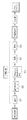
図1を用いて、自動車用ウインドシールドに用いられる合わせガラスの製造方法について説明する。まず、所望の形状に切断された1枚または複数のガラス板とそれらの間に同じく所望の形状に切断された樹脂フィルムを介在させて積層した未圧着体を準備する。未圧着体1は、予備圧着用の袋部材4内に搬入され(S1)、袋部材4の開口部がシールされる(S2)。次に、袋部材4内に残留している空気が脱気され袋部材4により未圧着体1が押圧される(S3)。脱気と同時また脱気の開始前後で加熱が開始され(S4)、予備圧着装置を用いて未圧着体1が加熱加圧される。所望の加熱加圧後に袋部材4から予備圧着されたガラス積層体が搬出され(S5)予備圧着体1’となる。さらに、予備圧着体1’は、オートクレーブ等の本圧着装置を用いて高温高圧下で加熱加圧さることにより本圧着され、合わせガラス1’’が製造される。
The manufacturing method of the laminated glass used for the windshield for motor vehicles is demonstrated using FIG. First, an uncompressed body is prepared by laminating one or a plurality of glass plates cut into a desired shape and a resin film similarly cut into a desired shape interposed therebetween. The
図2には、予備圧着装置30が示されている。予備圧着装置30は、未圧着体1を予備圧着装置30に搬入する搬入部材8と、合わせガラス製造用の保持器具2と、加熱室5と、予備圧着体1’を予備圧着装置から搬出する搬出部材9と、保持器具駆動用の二組の無端チェーン10とを備えている。さらに図示しない保持器具駆動機構、開口部開閉機構及び真空ポンプなどの減圧機構を備えている。
FIG. 2 shows the
図3に示すように合わせガラス製造用の保持器具2は、枠体3と袋部材4を備えている。袋部材4は、その詳細を後述するが、2枚の略矩形のゴム引布を重ね合わせて、一辺を接着せずに開口部とし、残り三辺を加硫接着などにより封止している。袋部材4の開口部は、2つの唇片を有し、そのうちの一方に棒状部材4bが取り付けられている。該棒状部材4bが取り付けられた一方の唇片が、矢印で示したようにもう一方の唇片を覆い隠すように重なることにより、開口部がシールされ、袋部材4を密封し得る構造となっている。開口部は、未圧着体の搬入側(図2中の左端位置)では、開口部開閉機構が、棒状部材4bを引き上げることにより袋部材4を開口させることにより未圧着体1の搬入が可能になる。一方、搬出側(図2中の右端位置)では、棒状部材4bの自重により棒状部材4bが取り付けられた一方の唇片が移動して開口部のシールが解放される。また、袋部材4は開口部と対向し、かつ、封止された辺4zの近傍に、後述する第1及び第2の脱気口7a,7bを備える。したがって、袋部材4は、湾曲した未圧着体1を収納できるだけの可撓性とともに、開口部がシールされた状態においては、袋部材4の内部を減圧脱気できる気密性とを有している。
As shown in FIG. 3, the holding
以下図1〜3を用いて予備圧着工程を説明する。予備圧着装置30の搬入側で未圧着体1が、搬入部材8によって、合わせガラス製造用の保持器具2の袋部材4内に搬入される(図1のステップS1)。未圧着体1が袋部材4内に収納される際、袋部材4の開口部の開閉は棒状部材4bの移動によって行われるが(図1のステップS2)、その動作の詳細は後述する。未圧着体1が収納されて開口部がシールされた袋部材4は、減圧機構(図示しない)によって脱気される。脱気された袋部材4は大気圧によって未圧着体1と密着し、未圧着体1を押圧する(図1のステップS3)。この袋部材4からの押圧によって未圧着体1が加圧され、また、加熱装置(図示せず)により加熱されることにより予備圧着が行われる。また、この袋部材4の押圧は、予備圧着装置30における搬送中においても袋部材4の内部で未圧着体が移動せず、未圧着体1を安定して保持できるという効果も備える。なお、予備圧着工程における加熱は、一般に加圧後に行うが、袋部材4内の脱気を妨げない範囲で加圧前に予備的な加熱を行ってもよい。
Hereinafter, the preliminary press-bonding step will be described with reference to FIGS. The
未圧着体1が収納された合わせガラス製造用の保持器具2は、他の複数の合わせガラス製造用の保持器具2とともに、枠体3によって2組の無端チェーン10の間に等間隔で取り付けられている。各無端チェーン10は2つの歯車の間に張りわたされており、鉛直平面に沿って回転する。複数の合わせガラス製造用の保持器具2は、無端チェーン10に立設されて保持器具駆動装置により回転移動する。保持器具2は、移動しながら減圧装置(図示せず)によって減圧され、未圧着体1は袋部材4内で押圧される。
The holding
さらに、未圧着体1を収納した合わせガラス製造用の保持器具2は、回転移動する軌道経路上に配置された加熱室5内において加熱処理が行われる(図1のステップS4)。加熱室5を通過した保持器具2は、予備圧着装置30の搬出側に到達するまでに冷却される。
搬出位置に到達した袋部材4の開口部は、棒状部材4bが自重により移動してシールが解放されて開口し、袋部材4内が大気圧となる。次に予備圧着された予備圧着体1’は開口部から、搬出部材9によって予備圧着装置30の袋部材4から搬出される。(図1のステップS5)。空になった保持器具2は、予備圧着装置30の下部を通り、搬入部材8の配置位置に移動して上記の工程を繰り返す。予備圧着が完了した予備圧着体1’は、次工程の本圧着装置(オートクレーブ)に送られて本圧着が施され合わせガラス1’ ’が製造される。Furthermore, the laminated glass
The opening of the
本実施形態では、袋部材4が、鉛直面内に沿って回転する二組の無端チェーン10に枠体3を介して複数取り付けられ、互いに隣接して多数設置され回転する予備圧着装置30を用いる。本発明は、特許文献1のように水平面内に沿って回転する無端チェーン10に袋部材4が上下方向に立設された状態で複数設置された予備圧着装置にも適用することができる。また、袋部材4を無端チェーンなどの駆動装置を設置せずに、単独で又は複数の合わせガラス製造用の保持器具2をバッチ式で減圧加熱が可能な空間に搬入搬出して未圧着体1を予備圧着するような態様とすることもできる。
In the present embodiment, a plurality of
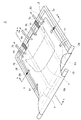
次に、図3、図4を用いて、合わせガラス製造用の保持器具2の構成について詳細に説明する。図3は、袋部材4の中に未圧着体1が収納され、袋部材4が密閉された状態における合わせガラス製造用の保持器具2を示している。また、図4は、袋部材4の開口部が開口された状態における合わせガラス製造用の保持器具2を示している。
Next, the configuration of the holding
合わせガラス製造用の保持器具2を構成する袋部材4は、2枚の略矩形のゴム引布を重ね合わせた封筒状をなしており、開口部と対向する辺4z側の中央付近に延長部4aを備える。袋部材4の一辺(第1の辺4w)は接着せず開口部となし、残り三辺は加硫接着などにより封止されている。以下本願において、封止されている3辺のうちで、開口部をなす第1の辺4wの両端から延びている辺をそれぞれ第2の辺4x及び第3の辺4yと呼び、第1の辺4wと対向しているものを第4の辺4zと呼ぶこととする。
袋部材4の開口部は、2つの唇片を備え、2つの唇片のうち1つの唇片が他方よりも長く、長いほうの唇片に棒状部材4bが取り付けられている。棒状部材4bの長さは枠体3の幅よりも若干長いほうが好ましい。The
The opening of the
枠体3は、袋部材3の外縁に沿った略長方形であって、第1の辺4wに対応する枠部材3w、第2の辺4xに対応する枠部材3x、第3の辺4yに対応する枠部材3y、第4の辺4zに対応する枠部材3zを備えている。枠部材3x及び枠部材3yは、それぞれ、袋部材4の封止された周縁部において互いに対向して配設された第1の枠部材及び第2の枠部材を構成する。また、枠部材3wは、袋部材4の開口部に平行に設けられる第3の枠部材を構成する。枠部材3zは、袋部材4の開口部に対向する第4の枠部材を構成する。略長方形の袋部材4は、開口部と対向する第4の辺4zの中央部付近に延長部4aが設けられている。
The
袋部材4の開口部を形成する第1の辺4wは、棒状部材4bとともに枠体3の第3の枠部材3wから枠体3の外側にはみ出すように設けられている。一方、袋部材4の封止された辺は枠体3の内側に支持されている。換言すれば、枠体3の第1の枠部材3x及び第2の枠部材3y及び第4の枠部材3zは袋部材4の封止された第2〜第4の辺4x、4y、4zの外側を囲むように配設されている。
The
袋部材4の開口部の第1の辺4wにおいては、2つの唇片のうち1つの唇片が他方よりも長く、長いほうの唇片に棒状部材4bが取り付けられている。未圧着体1が袋部材4の中に搬入された後、長い方唇片の第1の辺4wが棒状部材4bとともに図3の矢印のように第3の枠部材3wを越えてもう一方の唇片を覆い隠すように重なる。さらに、枠体3の反対側(図中裏面側)に回されることによって、袋部材4の開口部がシールされて袋部材4は密閉状態とすることができる。
In the
予備圧着装置30の搬入側では、袋部材4の開口部の一方の唇片に取り付けられた棒状部材4bが例えば、開口部開閉機構によって持ち上げられることにより、袋部材4は図4に示すように開口される。また、予備圧着装置30の搬出側では、棒状部材4bの棒状部材4bの取り付けられた一方の唇片が自重により移動し、開口部のシールが解放され開口状態となる。開口状態では、未圧着体1を袋部材4の中に搬入したり、予備圧着が終了した予備圧着体1’を袋部材4から搬出したりすることが可能となる。
On the carry-in side of the
前述のような予備圧着装置30においては、未圧着体1は合わせガラス1’’になった時の上下方向を進行方向に対して平行に袋部材4に挿入される。これは、脱気装置や加熱装置に対して未圧着体がほぼ左右対称になり均一な加圧加熱を得られるためである。また、左右対称に挿入載置することにより予備圧着装置30内で保持器具2のピッチをできるだけ詰めることが可能になり、生産性やタクトアップに貢献し、効率的で省エネルギーな生産を実現する。
In the
ここでは、未圧着体1がウインドシールドとして取り付けられた際の上下方向を進行方向に対して平行に袋部材4に挿入される例をしめしたが、保持器具の固定構造、脱気口や加熱機構に合わせて未圧着体1の左右方向を進行方向として袋部材4に挿入することも可能である。
Here, an example in which the
袋部材4は、弾性体であるつる巻バネ6bで枠体3に支持されている。このバネ6bは、未圧着体1が収納される袋部材4を枠体3から吊持するように、それぞれの辺とそれに対応した枠部材、例えば、第2の辺4xと第2の枠部材3xとの間及び第3の辺4yと第3の枠部材3yとの間に設けられる。
The
つる巻バネ6bは、枠体3に対して袋部材4の周縁部が移動の自由度の高い側の第2の辺4x、第3の辺4yの略中央部よりも第4の辺4zに近い位置に配されるのが好適である。一方で、本態様で開口部を備える第1の辺4wは第1の枠部材3wから吊持されていないため、つる巻バネ6bを取り付ける必要はない。つる巻バネ6bは、袋部材4の第2の辺4x及び第3の辺4yと第1の枠部材3x及び第2の枠部材3yとの間に取り付けられる。このため、枠体2と袋部材4の距離の調整が可能になる。すなわち、枠体3が形成する保持面に平行方向に移動自在に袋部材4が吊持される。
The
また、つる巻バネ6bは、枠体3が形成する保持面に対して平行方向及び法線方向に移動自在に袋部材4を吊持している。ここで、袋部材4内部を脱気すると第2の辺4x及び第3の辺4yで2枚のゴム引布同士が密着しようとするが、収納されている未圧着体1の曲面形状のゆえに袋部材4の2枚のゴム引布の形状に差異が生じる。その際に、袋部材4に生じる撓みによって可撓性の袋部材4の周縁部の形が変化しても、枠体3に対して袋部材4が保持面と平行及び法線方向に移動して枠体3との距離を調整することができる。
Further, the
このため、従来のベルト等による袋部材4の支持に比べ、ゴム引布から未圧着体1に加わる応力の緩和効果が生じ、枠体3から袋部材4にかかる応力のばらつきが小さくなる。その結果、未圧着体1に加わる脱気による圧着力が均一化された予備圧着行うことが可能になる。また、さまざまな湾曲形状の未圧着体1において均一な予備圧着が可能となり、予備圧着工程での割れ不良も減少させることができる。
For this reason, compared with support of the
この様に、弾性体であるつる巻バネ6bを用いると、未圧着体1が深曲げやより複雑な複曲面を持つような形状であっても、枠体3に対して袋部材4の周縁部が移動自在であるため、容易に枠体3との距離の調整をすることができる。枠体3に対して袋部材4を吊持する距離が、袋部材4の距離が枠体3から袋部材4にかかる力と弾性体の変形する力の均衡により自立的に定まり、袋部材4の保持位置が安定する。また、それにより構造が簡素になり、故障の少ない合わせガラス製造用の保持器具2を安価に提供することができる。
In this way, when the
一方で、支持部材はこれに限定されるものではなく、袋部材4の第2の辺4x及び第3の辺4yと枠体3の第1の枠部材3x及び第2の枠部材3yとの距離を移動自在に支持できるものであればよい。例えば、第1の枠部材3xの方へ付勢された流体シリンダーやガイドレールを用いて第1の枠部材3xの方へ付勢された器具であってもよい。
On the other hand, the support member is not limited to this, and the
バネ(弾性体)としては、加熱室5内の温度120℃〜150℃、好ましくは200℃まで使用可能なスチール製のつる巻バネが好適に用いられる。つる巻バネなどの弾性体を用いれば、袋部材4を吊持する簡素な構成とすることができる。また、適切な材質の選択により、合わせガラス製造用の保持器具2の全体を加熱する場合においても支持部材を冷却する必要がない。また、つる巻バネは簡素な機構と簡易な維持管理で十分に支持部材としての機能を発揮させることができため、熱的な安定性やコストの点で好適に用いることができる。一方で、バネ以外の弾性体としては、例えばゴムや圧縮性の流体を封じ込めたシリンダーなど公知の弾性支持手段を適用することもできる。
As the spring (elastic body), a steel helical spring that can be used up to a temperature of 120 ° C. to 150 ° C., preferably 200 ° C. in the
図5は、本発明に係る袋部材を示す平面模式図である。袋部材4は扁平形状の袋部材であり、該袋部材の外周の開口部と対向する辺4zの中央部付近に延長部4aを備える。さらに、延長部4aには、袋部材内部から空気を抜くための第1の脱気口7aが設けられている。延長部4aは、図示されるように、袋部材4の開口部を備える第1の辺4wを4等分した長さで、保持器具2においては第1の枠部材3xと第2の枠部材3yの端部を結んで形成される領域、袋部材4においては第1の辺4wの端部から延びる周縁部の第2の辺4xと第3の辺4yの端部を結んで形成される領域を第1の辺4wに直交する方向に袋部材4を分割した4つの領域のうち、中央部の二つの領域(図のA領域)から伸延して形成されている。
FIG. 5 is a schematic plan view showing a bag member according to the present invention. The
詳しくは、該4等分した領域の中央部の二つの領域を形成する開口部側第1の辺4wに含まれる中央部の線分(図中の上辺実線中央部)と、当該中央部の線分の両端を通り第2の辺4x及び第3の辺4yに平行な線分(図中上下方向の破線)によって画定される中央部分Aから伸延して形成される。延長部4aの突出長さは、未圧着体1が延長部4aに最も近い位置まで挿入されたとしても延長部4aに設置した第1の脱気口7aと未圧着体1に接触しない範囲で設定される。ここでは開口部に対向する辺4zの中央部分Aの全体から延長部4aが伸延する例を示したが、本発明はこれには限定されず脱気口7aからの脱気を妨げない範囲で、延長部4aの幅や伸延長さは適宜設計することができる。
このときの開口部の幅は、挿入されるガラス板の大きさによって適宜設定可能であるが、一般的な自動車用の窓ガラスの大きさから1500〜3000mmであれば量産される自動車用のウインドシールドの大部分に適用することができる。好ましくは、1600〜2400mmであれば深曲げ形状のガラスに好適に用いることができ、1800〜2200mmであれば既存の予備圧着設備にそのまま利用できて好ましい。このとき後述する第2の領域(図中のB領域)は第1及び第2の枠部材3x、3yを平行方向に周縁部側の全幅の30%以内または周縁部から800mm以内が好ましく、全幅の25%以内または600mm以内がさらに好ましい。一方で、全幅の10%以内または400mm以下になると領域を分ける効果が薄れ、全幅の5%以内または200mm以下では従来の脱気口の位置との効果の差が余りなくなる。Specifically, a central line segment (upper solid line central portion in the figure) included in the opening side
The width of the opening at this time can be set as appropriate depending on the size of the glass plate to be inserted, but if it is 1500 to 3000 mm from the size of a general automotive window glass, it will be mass-produced automotive window. It can be applied to most of the shields. Preferably, if it is 1600-2400 mm, it can be used suitably for the glass of a deep bending shape, and if it is 1800-2200 mm, it can utilize as it is for the existing preliminary crimping equipment, and is preferable. At this time, the second region (B region in the figure) to be described later is preferably within 30% of the total width on the peripheral edge side in the parallel direction of the first and
脱気口は、第1の脱気口7aが設けられた中央部分A以外の部分に第2の脱気口7bが設けることができる。中央部分A以外の部分とは、袋部材4を分割した4つの領域のうちの中央部分A以外の部分で画定される両端部分Bであって、未圧着体1と接触しない位置である。さらにこのように、第1及び第2の脱気口7a,7bは、未圧着体1と接触しない領域に設けられるので、未圧着体1は、第1の脱気口7aと接触して破損することはない。
The deaeration port can be provided with the
また、図3〜図5のように、中央部分A及び両端部分Bの双方に第1及び第2の脱気口7a,7bを設置すると、脱気を迅速に行いうる。この場合、第1及び第2の脱気口7a,7bによる脱気を開始するタイミングに時間差を設けて、先に第1の脱気口7aから脱気し、未圧着体1の配された領域の残留空気を予め減じた後に第2の脱気口7bからの脱気を始めると、効率よく脱気することができる。
Moreover, if the 1st and
図3、図5では、中央部分A及び両端部分Bの双方に第1及び第2の脱気口7a,7bを設置するとしたが、中央部分Aのみに第1の脱気口7aを設けるだけでも、両端部分Bに脱気口を設ける従来技術に比して脱気時間を短縮することができる。また、中央部分A及び両端部分Bの一方に脱気口を設けることも可能である。
3 and 5, the first and
図6は、本発明の合わせガラス製造用の袋部材4を用いて深曲げ形状の未圧着体1を予備圧着する場合の脱気の様子を示す模式図である。図6(a)〜(c)はいずれも前記合わせガラス製造用の袋部材4の図3におけるB−B線矢視断面図であり、それぞれ図6(a)は脱気する前、図6(b)は、脱気が始まって空気が少し減った状態、図6(c)は、さらに脱気が進んだ状態を示している。
FIG. 6 is a schematic view showing the state of deaeration when pre-pressing the deeply bent
袋部材4の延長部4aに設けた第1の脱気口7aから先に脱気を開始すると、中央空隙I及び周辺空隙Oが脱気される。脱気が進行し、袋部材4を構成する一方のゴム引布(図中、上方のゴム引布)が未圧着体1に接するようになると、主として中央空隙Iのみでの脱気が進んで図6(b)の状態になる。ここで、袋部材4の両端部分に設けた第2の脱気口7bからの脱気を開始する。その結果、第1及び第2の脱気口7a,7bからの脱気が進んで、未圧着体1の全体が均一に押圧されて袋部材4と密着する図6(c)の状態となる。
When deaeration is started first from the
図6のように脱気が進行していくと、未圧着体1の湾曲にあわせて袋部材4の両縁部は、中央に引き寄せられ、袋部材4に生じる撓みによって可撓性の袋部材の周縁部の形が変化する。このとき、袋部材4の周縁部は枠体3の第1及び第2の枠部材3x,3yから遠ざかる方向に移動しようとする。このとき、本発明の袋部材4は、枠体3との距離の調整が容易で袋部材4の変形や脱気に支障が生じない。これは、枠体3の第1及び第2の枠部材3x,3yに対してつる巻バネ6bによって支持されているため、枠体3に対して袋部材4の周縁部が移動自在であるためである。
When deaeration proceeds as shown in FIG. 6, both edge portions of the
また、このように、未圧着体1が深曲げ形状であって袋部材4内の大きな中央空隙Iに空気が大量に存在する場合であっても、その部分に対応する位置に第1の脱気口7aを設けているので、迅速に脱気することが可能である。
As described above, even when the
また、本実施形態では、第1及び第2の脱気口7a,7bから脱気を開始するタイミングをずらしたが、例えば第1及び第2脱気口7a,7bからの脱気を同時に開始しても途中で第2の脱気7bからの脱気を停止したり、第2の脱気口7bから脱気する空気量を第1の脱気口7aから脱気する空気量よりも減らすような制御を行ったりしても同様の効果を得ることが可能である。また、脱気口の数も実施例に限定されず、適宜変更可能であり、本発明の効果を存しない範囲で、一部の第2の脱気口7bから少量の脱気を第1の脱気口7aより先に開始することも可能である。
In this embodiment, the timing for starting degassing from the first and
また、袋部材4の両端部分Bの未圧着体1と接触しない領域にも第2の脱気口7bを備えているので、未圧着体1の形状に合わせて、第1の脱気口7aと第2の脱気口7bの脱気量及び/又は脱気を開始するタイミングを調整することが可能になり、未圧着体1の搬入された袋部材4の中央部分Aと袋部材の両端部分Bとで脱気がよりバランスよく行うことができる。
Moreover, since the
また、袋部材3の中央部分Aと両端部分Bとで脱気がバランスよく行われて袋部材3内に残る空気量を減らすことができる。また、第1の脱気口7aからの脱気を開始した後に第2の脱気口7bからの脱気タイミングと脱気量を制御することにより両端部分Bに比べて脱気のしにくい中央部分Aや深曲げ部など脱気を確実に行うことができ、より均一な予備圧着を実現できる。これらの結果、予備圧着体1’の全面にかかる圧力が均一化され、予備圧着不良を発生させることなく予備圧着体1’を製造することができる。また、第1及び第2の脱気口7a,7bから共に脱気を行うことで脱気効率が向上して予備圧着時間を短縮するとともに、圧着不良の発生をさらに防止しうる。
Moreover, deaeration is performed in a balanced manner between the central portion A and the both end portions B of the
また、第1の脱気口7aからの脱気を開始した後に加熱を開始した場合は、加熱前に真空度を上げることが可能になり袋部材4と未圧着体1の密着性が向上する。加熱と加圧の開始タイミングは装置の構成などにより適宜変更可能であり、先に加熱を開始することもできる。何れの場合においても予備圧着体1’への加熱と加圧を少なくとも一定時間同時に行うことにより、ガラス板1a,1a’と樹脂フィルムがしっかりと接触した状態で加熱が行われる。その結果、予備圧着体1’の圧着をより確実かつ均一に行うことができる合わせガラスの製造方法を提供できる。また、加熱エネルギーを予備圧着体1’に空気層を介さずに伝えることが可能になり、効率的な熱利用ができ省エネルギーにも貢献する。
In addition, when heating is started after degassing from the
次に、袋部材4の形状のバリエーションについて図7を用いて説明する。袋部材4は、それを容易に製造する点から、略多角形扁平形状のものが好ましいが、図3〜図5に示した略長方形の形状以外に例えば図7の(a)〜(c)に示されるような異なる形状の袋部材を用いることもできる。なお、ここで略多角形扁平形状とは、三角形、四角形、五角形などの多角形を基本に、それを形成する辺や、袋を形成する面が曲線や曲面を備えるなどの類似の形状を含むものとする。
Next, variations in the shape of the
図7の(a)に示される袋部材4は、開口部に対向する第4の辺が4z1及び4z2の2辺からなり、当該2つの辺4z1,4z2、第1の辺4w、第2の辺4x及び第3の辺4yを有するホームベース形状の5角形状である。(b)に示される袋部材4は、開口部に対向する第4の辺が弧状の辺4zからなり、当該弧状の辺4z、第1の辺4w、第2の辺4x及び第3の辺4yとで画定される形状を有する。また、(c)に示されるような袋部材4は、第2の辺、第3の辺及び第4の辺が一体となって円弧を形成しており、当該円弧と第1の辺4wとを有する略半円形状をなしている。
In the
袋部材4が図7の(a)〜(c)に示される形状のような開口部に対向する辺4zの形状が、未圧着体1を袋部材4の奥まで挿入し得ない形状であるとき、中央部分の第1の脱気口7aは、未圧着体1が収納可能な範囲外に位置する。このため、未圧着体1の端部が第1の脱気口7aと接触することを容易に避けることができ、延長部4aを設けた場合と同様の効果が得られる。中央部分に設置する第1の脱気口7aは、図7の(a)等に示すように1個設ける形態、図7の(b)に示すように複数個設ける形態のいずれの形態をも採用し得る。
The shape of the
図7(d)に示されるように、図5などに示される延長部4aを有しない構造も利用可能である。図7(d)では、袋部材4が第1〜第4の辺4w,4x,4y,4zを有する略方形であって、延長部4aの代わりに袋部材4内への未圧着体1の配置及び固定できる手段を備える。図7の(d)の態様では、図に示すように略矩形の袋部材4の中央下部に、未圧着体1の固定手段として、袋部材構成用のゴム引布同士をスポット的に加硫圧着したスポット圧着部11を設けて袋部材4の奥側(図の下側)への移動を規制し、第1の脱気口7aと未圧着体1の接触を防止している。この場合、スポット圧着部11より下の、未圧着体1が配置されない位置に第1の脱気口7aを設けることができる。
以上のように第1の脱気口7aは、袋部材4の中心線に近い領域の開口部から離れたガラス板1a,1a’と接触しない位置に配置することができる。また、第2の脱気口7bは、開口部から離れた領域で第1又は第2の枠部材3x、3yの近傍に設けることができる。即ち、図7の(a)、(b)、(d)などの第4の辺4zの端部がコーナ部を形成する態様においては、第2の脱気口7bはコーナ部近傍に形成することが好まし。また、コーナ部から800mm以内、好ましくは600mm以内、さらに好ましくは400mm以内に設けられると第1の脱気口7aとの協働により深曲げ形状に袋部材を適切に追従しながら迅速に袋部材4内部を脱気することができる。As shown in FIG. 7D, a structure without the
As described above, the
延長部4aに取り付ける第1の脱気口7aは、図8に示されるように、延長部4a内のピットに通じる部分にはロープ等の通気用スペーサを設けることが好ましい。ピットに通じる延長部4aが密着して脱気する空気の流れが妨げられないようにするためである。また、図7の(a)〜(d)に示される袋部材4においても、脱気口7の近傍に通気用スペーサを設けることが好ましい。これにより図8の場合でも延長部4aと同様の効果が期待できる。
As shown in FIG. 8, the
図3に示される態様で、合わせガラス製造用の保持器具2は袋部材4を保持する可撓性保持部材としての可撓性ベルト6aを備えている。可撓性ベルト6aは、第3の枠部材3wと第4の枠部材3zとの間に、開口部に略直角方向に保持面に沿って2本同方向に張設される。可撓性ベルト6aの長さは、第3の枠部材3wと第4の枠部材3zとの間隔よりも長く、枠体3が水平状態にあって、つる巻きばね6bで吊持された未圧着体1を収容した袋部材4が自重により下に下がろうとした場合、下がりすぎない適正な範囲に可撓性ベルト6aによって支持される。
In the embodiment shown in FIG. 3, the holding
袋部材4の下面は、枠体3の各部材で形成される保持面に対して法線方向において当該面よりも沈んだ位置までは移動可能であり、保持面に平行方向では移動自在となる。そのため、袋部材4が脱気されて2枚のゴム引布が未圧着体1に密着するとき、袋部材4が沈まない場合と比較すると、図3のA−A断面図である図9に示されるように、上下面のそれぞれのゴム引布にかかる応力の差は小さくなる。その結果、予備圧着体1’にかかる圧力は均一化され、また、袋部材4の開口部における皺の発生が抑制される。その結果、袋部材4の開口部からの空気のリークによる押圧不足を削減でき、予備圧着体1’の品質を向上させることができる。
The lower surface of the
また、可撓性ベルト6aを使用することによって枠体3に対する袋部材4の保持位置が、つる巻バネ6bだけで保持した場合とくらべて、可撓性ベルト6aの張設された側は、その変形可能範は一定範囲に規制される。これにより、枠体3から袋部材4にかかる主に表裏面の応力を均一化される。
In addition, when the
また、図2に示すように、多数の合わせガラス製造用の保持器具2を近接させて立設する予備圧着装置30のような態様を用いて予備圧着を行う場合、合わせガラス製造用の保持器具2も狭い間隔で立設される。この場合も、可撓性ベルト6aによって袋部材4が少なくとも可撓性ベルト6aが張設されている一方の側への移動を制限することができる。そのため、隣接した保持器具2の袋部材同士の接触を防止できる。同様に、ガラス製造用の保持器具2が水平状態から法線状態に移行する際にも、隣接する合わせガラス製造用の保持器具2の袋部材4に収容されている未圧着体1同士がぶつかって破損するのを防止することができる。
In addition, as shown in FIG. 2, when pre-compression is performed using an embodiment such as the
その結果、予備圧着装置30における支持部材2の取付間隔を縮めることが可能になり、未圧着体1の割れ不良を発生させずに生産性の高い合わせガラス製造用保持器具及び製造装置を提供できる。
As a result, it is possible to reduce the mounting interval of the
ここでは、可撓性ベルト6aが第3の枠部材3wと第4の枠部材3zとの間に2本同方向に張設される例を示したが、張設の仕方はこれには限定されない。その本数は1本や3本以上でもよく、固定する枠体も第1や第2の枠部材3x、3yでもよい。また、枠体と非平行に張設してもよく、複数の可撓性ベルト6aをクロスさせて張設することも可能である。
Here, an example in which two
可撓性ベルト6aの材質は、オートクレーブ及び予備圧着装置30の加熱条件下で使用可能な公知の材料が使用可能であるが、加熱室5内で120℃〜150℃、好ましくは200℃の温度に耐えられるように、ポリエステル繊維、全芳香族ポリアミド繊維などの耐熱性であることが好ましい。また、可撓性ベルト6aの形状としては、幅30〜100mm、厚さ1〜3mmであることが好ましい。
As the material of the
さらに、合わせガラス製造用の保持器具2は、袋部材4を枠体3の第1の枠部材3x、第2の枠部材3y及び第4の枠部材3zのうちの複数の枠部材に吊持する非伸縮性保持部材としての非伸縮性ベルト6cを備えうる。非伸縮性ベルト6cは、袋部材4の第2の辺4x及び第3の辺4yに各辺と平行方向に開口した筒状で袋部材4の周縁部に取り付けられる。該筒形状の中に第1の枠部材3x及び第2の部材3yが挿入されて枠体3と嵌合している。このとき、非伸縮性ベルト6cは、挿入された枠体の各部材が一定の範囲で移動できる程度に余裕を持たせた長さとし、第1の辺4wに近い位置に複数設けることが好ましい。袋部材4の第4の辺4zにおいては、非伸縮性ベルト6cを取り付ける位置は、辺4zに直接取り付けてもよく、延長部4aに取り付けることも可能である。また、ここでは筒状のベルトにより移動範囲を調整したが、調整は他の手段でもよく、バネ、シリンダ、ダンパーやガイド部材などでもよく、それらを組み合わせて用いてもよい。
Furthermore, the holding
非伸縮性ベルト6cを設けることによって未圧着体1を収納していな工程においても枠体3と袋部材の4の適正な位置関係の調整に寄与する。例えば、図2に示した予備圧着装置30において合わせガラス製造用の保持器具2は、無端チェーン10に沿った移動において予備圧着体1’の搬出側から未圧着体1の搬入側までの間、袋部材4は開口部側の第1の辺4wが第4の辺4zより下方に位置する姿勢をとる。このとき、枠体3と袋部材4の間隔を規制する非伸縮性ベルト6cを設けていないと、袋部材4は枠体3より下方にずれ下がってしまう。すると、袋部材4が未圧着体1の搬入位置に来たときに袋部材4に対して枠体3がずれたままでは未圧着体1を袋部材4内に円滑に搬入し得ず、袋部材4の位置を修正する必要が生じる。
Providing the
一方で、非伸縮性ベルト6cが設けてあると、袋部材4の枠体3からの位置ずれを一定範囲に抑制する。このため、予備圧着体1’の搬出位置から未圧着体1の搬入位置まで移動する間においても、袋部材4に対して枠体3の位置を修正する必要がない。したがって、搬入位置において、棒状部材4bを持ち上げて袋部材4の開口部を開放するだけで未圧着体1を袋部材4の中に円滑に搬入することができる。
On the other hand, when the
また、袋部材4の開口部側に設けられる非伸縮性ベルト6cは、横方向(第1の辺4z平行な方向)における袋部材4の開口部の枠体3に対する位置を一定の範囲に位置決めすることができる。したがって、未圧着体1及び予備圧着体1’の搬入搬出が容易に行いうる。また、未圧着体1を袋部材4内で横ずれなく収容するので、未圧着体1が押圧される場合に未圧着体1の応力が均一化され、例えば、ガラス板1a,1a’の一端に過大な圧力を受けて破損するなどの不良を低減することができる。
The
以上のように非伸縮性ベルト6cを取り付けることにより、袋部材4の未圧着体1が収容されている部分における変形を許容しつつ、それ以外の部分の枠体3からの位置ずれを一定範囲に抑制することができる。その結果、開口部の開閉の際の袋部材4の保持や保持器具2の移動時の枠体3と袋部材4の適正な距離の維持することが可能になる。これにより、合わせガラス製造用の保持器具2を用いた未圧着体1を搬入、搬送、搬出において、袋部材4の接触による割れ不良が削減されるとともに、取り扱いが容易になり、生産性の高い合わせガラス製造用の保持器具を実現できる。
By attaching the
本発明の合わせガラス製造用の保持器具2は、袋部材4の開口部の開閉において、袋部材4が枠体3に対してバネ6bにより支持されて、袋部材4の横方向(第1の辺4wと平行な方向)に長さ(即ち幅)は調節可能である。このため、袋部材4の変形の自由度が大きく開口を大きくすることが可能である。その結果、未圧着体1の袋部材4内への搬入及び予備圧着体1’の袋部材4からの搬出がさらに容易となる。また、袋部材4に搬入された未圧着体1の湾曲にあわせて袋部材4に生じる撓みによって、搬入後にも袋部材4が未圧着体1の湾曲に追従する。これにより、未圧着体1に加わる不要な応力の発生を低減して袋部材4に収納することができる。
In the
また、未圧着体1の搬入位置において、棒状部材4bを持ち上げ、搬入部材8により未圧着体1を袋部材4の中に搬入することができる。このとき、袋部材4はその下方を可撓性ベルト6aによって支持されているため、袋部材4内に収容されている未圧着体1はその下方に位置する他の合わせガラス製造用の保持器具2と接触して壊れることがない。
また、合わせガラス製造用の保持器具2が搬入位置から搬出位置まで移動する間においても、可撓性ベルト6aの存在によって、袋部材4内に収容されている未圧着体1が隣接する袋部材4内に収容されている未圧着体1と接触して壊れることもない。 In addition, the rod-
Further, even when the holding
また、予備圧着装置30の搬入側において、合わせガラス製造用保持器具2は、水平状態から鉛直上向きへとその姿勢が変化する。しかし、棒状部材4bを引き上げることにより袋部材4を開口させ、棒状部材4bを持ち上げるのをやめることで棒状部材4bの自重によって袋部材4の開口部を自動的にシールすることができる。
Moreover, on the carry-in side of the
また、予備圧着装置30の搬出側において、合わせガラス製造用の保持器具2は、鉛直上向きから水平の状態を経て鉛直下向きに角度を変える。搬出側では棒状部材4の自重により棒状部材4bが取り付けられた一方の唇片が移動して開口部のシールが解放される。
加熱室5で加熱された合わせガラス製造用の保持器具2は、搬出位置では既にほぼ冷却されている。予備圧着の完了した予備圧着体1’は、水平状態で搬出部材9を用いて搬出され、次の本圧着工程に送られる。Moreover, on the carry-out side of the
The
なお、上記図2や図3の実施形態では、可撓性ベルト6a、非伸縮性ベルト6c、第1の脱気口7aと第2の脱気口7b等をすべて備える構成を示した。しかし、これらの構成要件は、全部又は一部の特定の組み合わせを備える構成でなくても、個々に優れた作用効果を奏することはいうまでもない。また、上記実施の形態では深曲げ形状の合わせガラスについて説明したが、本発明は、深曲げ形状の合わせガラス用素材だけでなく、曲率が従来と同程度の曲面形状の合わせガラスの製造についても適用できることはいうまでもない。
2 and FIG. 3, the configuration including all of the
なお、本出願は、2008年12月24日出願の日本出願(特願2008−327866)に基づくものであり、その内容はここに参照として取り込まれる。 In addition, this application is based on the Japanese application (Japanese Patent Application No. 2008-327866) of an application on December 24, 2008, The content is taken in here as a reference.
1 :未圧着体
1’ :予備圧着体
1’’:合わせガラス
1a,1a':ガラス板
1b:樹脂
2:合わせガラス製造用の保持器具
3:枠体
3x:第1の枠部材
3y:第2の枠部材
3w:第3の枠部材
3z:第4の枠部材
4:袋部材
4a:延長部
4b:棒状部材
4w:第1の辺
4x:第2の辺
4y:第3の辺
4z:第4の辺
5:加熱室
6a:可撓性ベルト
6b:バネ
6c:非伸縮性ベルト
7a:第1の脱気口
7b:第2の脱気口
8:搬入部材
9:搬出部材
10:無端チェーン
11:スポット圧着部
30:予備圧着装置DESCRIPTION OF SYMBOLS 1: Uncrimped body 1 ': Pre-crimped body 1'': Laminated
Claims (5)
前記保持器具は、袋部材と、枠体と、前記袋部材を前記枠体に吊持する支持部材とを有し、
前記袋部材は、可撓性と気密性を有する膜からなり、前記袋部材の外周の第1の辺にシール可能な開口部が設けられ、前記第1の辺を除く周縁部が封止された扁平形状をなし、前記袋部材内部から空気を抜くための脱気口を備え、
前記枠体は、互いに対向して配設される第1の枠部材と第2の枠部材とを少なくとも備え、前記第1の枠部材及び前記第2の枠部材は前記袋部材の前記周縁部の外側に配設され、
前記支持部材は、弾性体であり、前記第1の枠部材と、前記第1の枠部材と対応する前記袋部材の辺との間、及び前記第2の枠部材と、前記第2の枠部材と対応する前記袋部材の辺との間にそれぞれ設けられ、前記袋部材を吊持する
ことを特徴とする合わせガラス製造用の保持器具。 A holding device used in a step of pre-bonding a non-bonded body in which a plurality of glass plates and at least one resin film are laminated in the production of laminated glass,
The holding device has a bag member, a frame, and a support member that suspends the bag member on the frame,
The bag member is made of a film having flexibility and airtightness, and an opening that can be sealed is provided on a first side of an outer periphery of the bag member, and a peripheral portion excluding the first side is sealed. Comprising a deaeration port for venting air from the inside of the bag member,
The frame body includes at least a first frame member and a second frame member disposed to face each other, and the first frame member and the second frame member are the peripheral portions of the bag member. Arranged outside the
The support member is an elastic body, and between the first frame member and the side of the bag member corresponding to the first frame member, the second frame member, and the second frame. A holding device for producing laminated glass, which is provided between a member and a side of the corresponding bag member and suspends the bag member.
前記第3の枠部材は、前記開口部に略平行に設けられ前記袋部材と係合することにより袋部材をシールし、
前記第4の枠部材は、前記開口部に略平行、かつ前記周縁部の外側に配設され、
前記第1から第4の枠部材のうちのいずれか複数の枠部材に吊持され、前記袋部材の下面を支持する可撓性保持部材を備える請求項1に記載の合わせガラス製造用の保持器具。 The frame includes a third frame member and a fourth frame member,
The third frame member is provided substantially parallel to the opening and seals the bag member by engaging with the bag member,
The fourth frame member is disposed substantially parallel to the opening and outside the peripheral edge,
It is suspended from the first to any plurality of frame members of the fourth frame member, the holding for the manufacturing of laminated glass according to claim 1, further comprising a flexible retaining member which supports the lower surface of the bag member Instruments.
前記保持器具は、袋部材と、枠体と、前記袋部材を前記枠体に吊持する支持部材とを有し、
前記袋部材は、可撓性と気密性を有する膜からなり、前記袋部材の外周の第1の辺にシール可能な開口部が設けられ、前記第1の辺を除く周縁部が封止された扁平形状をなし、前記袋部材内部から空気を抜くための脱気口を備え、
前記枠体は、互いに対向して配設される第1の枠部材と第2の枠部材とを少なくとも備え、前記第1の枠部材及び前記第2の枠部材は前記袋部材の前記周縁部の外側に配設され、
前記支持部材は、弾性体であり、前記第1の枠部材と、前記第1の枠部材と対応する前記袋部材の辺との間、及び前記第2の枠部材と、前記第2の枠部材と対応する前記袋部材の辺との間にそれぞれ設けられ、前記袋部材を吊持し、
前記予備圧着を行う工程は、
未圧着体を前記保持器具に搬入する工程と、
前記袋部材の開口部をシールする工程と、
前記袋部材の内部を脱気して前記未圧着体を押圧する工程と、
前記袋部材を加熱する工程と、
予備圧着された予備圧着体を前記保持器具から搬出する工程とを
少なくとも備える合わせガラスの製造方法。 A method for producing a laminated glass comprising a step of performing pre-compression using a holding device for pre-compression that can be heated and pressurized,
The holding device has a bag member, a frame, and a support member that suspends the bag member on the frame,
The bag member is made of a film having flexibility and airtightness, and an opening that can be sealed is provided on a first side of an outer periphery of the bag member, and a peripheral portion excluding the first side is sealed. Comprising a deaeration port for venting air from the inside of the bag member,
The frame body includes at least a first frame member and a second frame member disposed to face each other, and the first frame member and the second frame member are the peripheral portions of the bag member. Arranged outside the
The support member is an elastic body, and between the first frame member and the side of the bag member corresponding to the first frame member, the second frame member, and the second frame. Each provided between the side of the bag member corresponding to the member, the bag member is suspended,
The pre-bonding step includes
Carrying the uncompressed body into the holding device;
Sealing the opening of the bag member;
Degassing the inside of the bag member and pressing the unbonded body;
Heating the bag member;
A method for producing laminated glass comprising at least a step of carrying out the pre-pressed pre-pressed body from the holding device.
Priority Applications (1)
| Application Number | Priority Date | Filing Date | Title |
|---|---|---|---|
| JP2010544026A JP5774854B2 (en) | 2008-12-24 | 2009-12-17 | Holding device for laminated glass production, laminated glass production apparatus and method |
Applications Claiming Priority (4)
| Application Number | Priority Date | Filing Date | Title |
|---|---|---|---|
| JP2008327866 | 2008-12-24 | ||
| JP2008327866 | 2008-12-24 | ||
| PCT/JP2009/071065 WO2010073966A1 (en) | 2008-12-24 | 2009-12-17 | Bag member for compression prebonding, and holding tool for producing laminated glass, and device of producing laminated glass and method of producing the same |
| JP2010544026A JP5774854B2 (en) | 2008-12-24 | 2009-12-17 | Holding device for laminated glass production, laminated glass production apparatus and method |
Publications (2)
| Publication Number | Publication Date |
|---|---|
| JPWO2010073966A1 JPWO2010073966A1 (en) | 2012-06-14 |
| JP5774854B2 true JP5774854B2 (en) | 2015-09-09 |
Family
ID=42287580
Family Applications (1)
| Application Number | Title | Priority Date | Filing Date |
|---|---|---|---|
| JP2010544026A Expired - Fee Related JP5774854B2 (en) | 2008-12-24 | 2009-12-17 | Holding device for laminated glass production, laminated glass production apparatus and method |
Country Status (5)
| Country | Link |
|---|---|
| US (2) | US8287683B2 (en) |
| EP (1) | EP2371780A4 (en) |
| JP (1) | JP5774854B2 (en) |
| CN (1) | CN102264663B (en) |
| WO (1) | WO2010073966A1 (en) |
Families Citing this family (4)
| Publication number | Priority date | Publication date | Assignee | Title |
|---|---|---|---|---|
| US20120180943A1 (en) * | 2011-01-19 | 2012-07-19 | Ebs Concepts, Llc | Preheated Gas Evacuated High Pressure Plastic Laminating System |
| US10012480B2 (en) | 2013-07-03 | 2018-07-03 | Angel Armor, Llc | Ballistic resistant panel for vehicle door |
| JP6799965B2 (en) * | 2016-08-10 | 2020-12-16 | Toyo Tire株式会社 | Molded bag for laminated glass |
| CN107382100B (en) * | 2017-07-25 | 2020-02-14 | 重庆华瑞玻璃有限公司 | Laminated glass forming machine |
Citations (5)
| Publication number | Priority date | Publication date | Assignee | Title |
|---|---|---|---|---|
| JPS4999518A (en) * | 1973-01-25 | 1974-09-20 | ||
| EP0562142A1 (en) * | 1992-03-26 | 1993-09-29 | Peter Arrow Limited | Vacuum bag for making safety glass |
| JP2001294451A (en) * | 2000-04-10 | 2001-10-23 | Toyo Tire & Rubber Co Ltd | Heating and pressurizing bag for manufacturing laminated glass |
| JP2005104821A (en) * | 2003-09-11 | 2005-04-21 | Nakamura Yoshiko | Decompression envelope for manufacturing laminated glass |
| JP2006137625A (en) * | 2004-11-10 | 2006-06-01 | Toyo Tire & Rubber Co Ltd | Heating and pressurizing bag for manufacturing laminated sheet glass |
Family Cites Families (9)
| Publication number | Priority date | Publication date | Assignee | Title |
|---|---|---|---|---|
| US2714567A (en) * | 1952-10-17 | 1955-08-02 | Pittsburgh Plate Glass Co | Preliminary pressing of bent laminated glass |
| US2837453A (en) * | 1955-08-19 | 1958-06-03 | Pittsburgh Plate Glass Co | Preliminary pressing of laminated glass |
| US2996416A (en) * | 1959-04-06 | 1961-08-15 | Libbey Owens Ford Glass Co | Method and apparatus for laminating glass-plastic sandwiches |
| US4287015A (en) * | 1976-10-18 | 1981-09-01 | Danner Harold J Jun | Vacuum bag used in making laminated products |
| FR2561990A1 (en) * | 1984-04-02 | 1985-10-04 | Ppg Industries Inc | Suspended flexible rubber sheets for pre:laminating curved windscreens |
| US4601772A (en) * | 1985-02-11 | 1986-07-22 | Shatterproof Glass Corporation | Apparatus for producing laminated safety glass |
| JP3230600B2 (en) | 1992-03-02 | 2001-11-19 | 旭硝子株式会社 | Vacuum crimping method and device |
| JPH06345498A (en) | 1993-06-14 | 1994-12-20 | Aoyama Rubber Kk | Heated and pressure-reduced bag and production of joining material using the same |
| JP2004018293A (en) | 2002-06-13 | 2004-01-22 | Toyo Tire & Rubber Co Ltd | Rubber bag intake device for manufacturing laminated glass |
-
2009
- 2009-12-17 CN CN200980152689.7A patent/CN102264663B/en not_active Expired - Fee Related
- 2009-12-17 EP EP09834769.3A patent/EP2371780A4/en not_active Withdrawn
- 2009-12-17 JP JP2010544026A patent/JP5774854B2/en not_active Expired - Fee Related
- 2009-12-17 WO PCT/JP2009/071065 patent/WO2010073966A1/en active Application Filing
-
2011
- 2011-06-23 US US13/067,760 patent/US8287683B2/en not_active Expired - Fee Related
-
2012
- 2012-09-12 US US13/611,972 patent/US8475620B2/en not_active Expired - Fee Related
Patent Citations (5)
| Publication number | Priority date | Publication date | Assignee | Title |
|---|---|---|---|---|
| JPS4999518A (en) * | 1973-01-25 | 1974-09-20 | ||
| EP0562142A1 (en) * | 1992-03-26 | 1993-09-29 | Peter Arrow Limited | Vacuum bag for making safety glass |
| JP2001294451A (en) * | 2000-04-10 | 2001-10-23 | Toyo Tire & Rubber Co Ltd | Heating and pressurizing bag for manufacturing laminated glass |
| JP2005104821A (en) * | 2003-09-11 | 2005-04-21 | Nakamura Yoshiko | Decompression envelope for manufacturing laminated glass |
| JP2006137625A (en) * | 2004-11-10 | 2006-06-01 | Toyo Tire & Rubber Co Ltd | Heating and pressurizing bag for manufacturing laminated sheet glass |
Also Published As
| Publication number | Publication date |
|---|---|
| CN102264663B (en) | 2014-12-10 |
| US20120067517A1 (en) | 2012-03-22 |
| JPWO2010073966A1 (en) | 2012-06-14 |
| CN102264663A (en) | 2011-11-30 |
| US8475620B2 (en) | 2013-07-02 |
| US20130032291A1 (en) | 2013-02-07 |
| US8287683B2 (en) | 2012-10-16 |
| EP2371780A1 (en) | 2011-10-05 |
| WO2010073966A1 (en) | 2010-07-01 |
| EP2371780A4 (en) | 2014-02-26 |
Similar Documents
| Publication | Publication Date | Title |
|---|---|---|
| KR101191259B1 (en) | Method for crowning sheets of glass by pressing and suction | |
| JP5774854B2 (en) | Holding device for laminated glass production, laminated glass production apparatus and method | |
| CN109664494A (en) | A kind of display screen laminating apparatus and applying method | |
| JP4894984B2 (en) | Resin film coating method and coating apparatus | |
| CN1956929A (en) | Sheet bending apparatus using vaccum device and method thereof | |
| JP5251336B2 (en) | Method and apparatus for pre-bonding laminated glass using curved roll | |
| WO2011096447A1 (en) | Glass plate and method for manufacturing glass plate | |
| JP2019182743A5 (en) | Intermediate film for automobile windshield, roll-shaped body, automobile windshield and method for producing automobile windshield | |
| CN109435410A (en) | A kind of processing unit (plant) and applying method of Mobile phone screen | |
| JP6638656B2 (en) | Manufacturing method of laminated glass | |
| JP2014051065A (en) | Molding apparatus and molding method of prepreg laminated material | |
| US11192341B2 (en) | Method for producing a curved composite glass pane having a thin glass pane | |
| KR101122653B1 (en) | Method and device for crowning glass sheets | |
| JP2016064965A (en) | Method for producing laminated glass for vehicle | |
| CN109435409A (en) | A kind of film pressing device and applying method of Mobile phone screen | |
| CN110667226B (en) | Photovoltaic module packaging system and photovoltaic module packaging method | |
| KR102656831B1 (en) | How to bend glass sheets | |
| KR20200070332A (en) | How to control separation between glasses during ball-sagging to reduce final shape mismatch | |
| US20180194663A1 (en) | Method and apparatus for bending thin glass | |
| TW200422165A (en) | Laminating press device, vacuum laminating device, and vacuum laminating method | |
| CN209633977U (en) | A kind of laminating apparatus of Mobile phone screen | |
| JP7401781B2 (en) | Manufacturing method for lightweight laminated glass sheets for vehicles | |
| JP2008169052A (en) | Vacuum bag for laminated glass manufacture | |
| CN212365980U (en) | Solar cell module packaging system | |
| CN217751698U (en) | Polyvinyl butyral intermediate film anti-rolling cutting device |
Legal Events
| Date | Code | Title | Description |
|---|---|---|---|
| A621 | Written request for application examination |
Free format text: JAPANESE INTERMEDIATE CODE: A621 Effective date: 20121106 |
|
| RD04 | Notification of resignation of power of attorney |
Free format text: JAPANESE INTERMEDIATE CODE: A7424 Effective date: 20140218 |
|
| A131 | Notification of reasons for refusal |
Free format text: JAPANESE INTERMEDIATE CODE: A131 Effective date: 20140603 |
|
| A521 | Request for written amendment filed |
Free format text: JAPANESE INTERMEDIATE CODE: A523 Effective date: 20140731 |
|
| A02 | Decision of refusal |
Free format text: JAPANESE INTERMEDIATE CODE: A02 Effective date: 20150120 |
|
| A521 | Request for written amendment filed |
Free format text: JAPANESE INTERMEDIATE CODE: A523 Effective date: 20150318 |
|
| A521 | Request for written amendment filed |
Free format text: JAPANESE INTERMEDIATE CODE: A821 Effective date: 20150318 |
|
| A521 | Request for written amendment filed |
Free format text: JAPANESE INTERMEDIATE CODE: A523 Effective date: 20150410 |
|
| A911 | Transfer to examiner for re-examination before appeal (zenchi) |
Free format text: JAPANESE INTERMEDIATE CODE: A911 Effective date: 20150511 |
|
| TRDD | Decision of grant or rejection written | ||
| A01 | Written decision to grant a patent or to grant a registration (utility model) |
Free format text: JAPANESE INTERMEDIATE CODE: A01 Effective date: 20150602 |
|
| A61 | First payment of annual fees (during grant procedure) |
Free format text: JAPANESE INTERMEDIATE CODE: A61 Effective date: 20150702 |
|
| R150 | Certificate of patent or registration of utility model |
Ref document number: 5774854 Country of ref document: JP Free format text: JAPANESE INTERMEDIATE CODE: R150 |
|
| S531 | Written request for registration of change of domicile |
Free format text: JAPANESE INTERMEDIATE CODE: R313531 |
|
| R350 | Written notification of registration of transfer |
Free format text: JAPANESE INTERMEDIATE CODE: R350 |
|
| R250 | Receipt of annual fees |
Free format text: JAPANESE INTERMEDIATE CODE: R250 |
|
| S533 | Written request for registration of change of name |
Free format text: JAPANESE INTERMEDIATE CODE: R313533 |
|
| R350 | Written notification of registration of transfer |
Free format text: JAPANESE INTERMEDIATE CODE: R350 |
|
| LAPS | Cancellation because of no payment of annual fees |