JP5774401B2 - Appliance having a leak-free connection and manufacturing method - Google Patents
Appliance having a leak-free connection and manufacturing method Download PDFInfo
- Publication number
- JP5774401B2 JP5774401B2 JP2011161997A JP2011161997A JP5774401B2 JP 5774401 B2 JP5774401 B2 JP 5774401B2 JP 2011161997 A JP2011161997 A JP 2011161997A JP 2011161997 A JP2011161997 A JP 2011161997A JP 5774401 B2 JP5774401 B2 JP 5774401B2
- Authority
- JP
- Japan
- Prior art keywords
- electrical connection
- temperature
- conductor
- insulating layer
- environment
- Prior art date
- Legal status (The legal status is an assumption and is not a legal conclusion. Google has not performed a legal analysis and makes no representation as to the accuracy of the status listed.)
- Active
Links
Images
Classifications
-
- F—MECHANICAL ENGINEERING; LIGHTING; HEATING; WEAPONS; BLASTING
- F16—ENGINEERING ELEMENTS AND UNITS; GENERAL MEASURES FOR PRODUCING AND MAINTAINING EFFECTIVE FUNCTIONING OF MACHINES OR INSTALLATIONS; THERMAL INSULATION IN GENERAL
- F16C—SHAFTS; FLEXIBLE SHAFTS; ELEMENTS OR CRANKSHAFT MECHANISMS; ROTARY BODIES OTHER THAN GEARING ELEMENTS; BEARINGS
- F16C32/00—Bearings not otherwise provided for
- F16C32/04—Bearings not otherwise provided for using magnetic or electric supporting means
- F16C32/0406—Magnetic bearings
- F16C32/044—Active magnetic bearings
- F16C32/047—Details of housings; Mounting of active magnetic bearings
-
- H—ELECTRICITY
- H01—ELECTRIC ELEMENTS
- H01B—CABLES; CONDUCTORS; INSULATORS; SELECTION OF MATERIALS FOR THEIR CONDUCTIVE, INSULATING OR DIELECTRIC PROPERTIES
- H01B3/00—Insulators or insulating bodies characterised by the insulating materials; Selection of materials for their insulating or dielectric properties
- H01B3/18—Insulators or insulating bodies characterised by the insulating materials; Selection of materials for their insulating or dielectric properties mainly consisting of organic substances
- H01B3/30—Insulators or insulating bodies characterised by the insulating materials; Selection of materials for their insulating or dielectric properties mainly consisting of organic substances plastics; resins; waxes
- H01B3/42—Insulators or insulating bodies characterised by the insulating materials; Selection of materials for their insulating or dielectric properties mainly consisting of organic substances plastics; resins; waxes polyesters; polyethers; polyacetals
- H01B3/427—Polyethers
-
- H—ELECTRICITY
- H01—ELECTRIC ELEMENTS
- H01B—CABLES; CONDUCTORS; INSULATORS; SELECTION OF MATERIALS FOR THEIR CONDUCTIVE, INSULATING OR DIELECTRIC PROPERTIES
- H01B3/00—Insulators or insulating bodies characterised by the insulating materials; Selection of materials for their insulating or dielectric properties
- H01B3/18—Insulators or insulating bodies characterised by the insulating materials; Selection of materials for their insulating or dielectric properties mainly consisting of organic substances
- H01B3/30—Insulators or insulating bodies characterised by the insulating materials; Selection of materials for their insulating or dielectric properties mainly consisting of organic substances plastics; resins; waxes
- H01B3/44—Insulators or insulating bodies characterised by the insulating materials; Selection of materials for their insulating or dielectric properties mainly consisting of organic substances plastics; resins; waxes vinyl resins; acrylic resins
- H01B3/443—Insulators or insulating bodies characterised by the insulating materials; Selection of materials for their insulating or dielectric properties mainly consisting of organic substances plastics; resins; waxes vinyl resins; acrylic resins from vinylhalogenides or other halogenoethylenic compounds
- H01B3/445—Insulators or insulating bodies characterised by the insulating materials; Selection of materials for their insulating or dielectric properties mainly consisting of organic substances plastics; resins; waxes vinyl resins; acrylic resins from vinylhalogenides or other halogenoethylenic compounds from vinylfluorides or other fluoroethylenic compounds
-
- F—MECHANICAL ENGINEERING; LIGHTING; HEATING; WEAPONS; BLASTING
- F16—ENGINEERING ELEMENTS AND UNITS; GENERAL MEASURES FOR PRODUCING AND MAINTAINING EFFECTIVE FUNCTIONING OF MACHINES OR INSTALLATIONS; THERMAL INSULATION IN GENERAL
- F16C—SHAFTS; FLEXIBLE SHAFTS; ELEMENTS OR CRANKSHAFT MECHANISMS; ROTARY BODIES OTHER THAN GEARING ELEMENTS; BEARINGS
- F16C2202/00—Solid materials defined by their properties
- F16C2202/30—Electric properties; Magnetic properties
-
- F—MECHANICAL ENGINEERING; LIGHTING; HEATING; WEAPONS; BLASTING
- F16—ENGINEERING ELEMENTS AND UNITS; GENERAL MEASURES FOR PRODUCING AND MAINTAINING EFFECTIVE FUNCTIONING OF MACHINES OR INSTALLATIONS; THERMAL INSULATION IN GENERAL
- F16C—SHAFTS; FLEXIBLE SHAFTS; ELEMENTS OR CRANKSHAFT MECHANISMS; ROTARY BODIES OTHER THAN GEARING ELEMENTS; BEARINGS
- F16C2300/00—Application independent of particular apparatuses
- F16C2300/40—Application independent of particular apparatuses related to environment, i.e. operating conditions
- F16C2300/42—Application independent of particular apparatuses related to environment, i.e. operating conditions corrosive, i.e. with aggressive media or harsh conditions
-
- F—MECHANICAL ENGINEERING; LIGHTING; HEATING; WEAPONS; BLASTING
- F16—ENGINEERING ELEMENTS AND UNITS; GENERAL MEASURES FOR PRODUCING AND MAINTAINING EFFECTIVE FUNCTIONING OF MACHINES OR INSTALLATIONS; THERMAL INSULATION IN GENERAL
- F16C—SHAFTS; FLEXIBLE SHAFTS; ELEMENTS OR CRANKSHAFT MECHANISMS; ROTARY BODIES OTHER THAN GEARING ELEMENTS; BEARINGS
- F16C32/00—Bearings not otherwise provided for
- F16C32/04—Bearings not otherwise provided for using magnetic or electric supporting means
- F16C32/0406—Magnetic bearings
- F16C32/044—Active magnetic bearings
- F16C32/0444—Details of devices to control the actuation of the electromagnets
- F16C32/0446—Determination of the actual position of the moving member, e.g. details of sensors
-
- F—MECHANICAL ENGINEERING; LIGHTING; HEATING; WEAPONS; BLASTING
- F16—ENGINEERING ELEMENTS AND UNITS; GENERAL MEASURES FOR PRODUCING AND MAINTAINING EFFECTIVE FUNCTIONING OF MACHINES OR INSTALLATIONS; THERMAL INSULATION IN GENERAL
- F16C—SHAFTS; FLEXIBLE SHAFTS; ELEMENTS OR CRANKSHAFT MECHANISMS; ROTARY BODIES OTHER THAN GEARING ELEMENTS; BEARINGS
- F16C32/00—Bearings not otherwise provided for
- F16C32/04—Bearings not otherwise provided for using magnetic or electric supporting means
- F16C32/0406—Magnetic bearings
- F16C32/044—Active magnetic bearings
- F16C32/0459—Details of the magnetic circuit
- F16C32/0461—Details of the magnetic circuit of stationary parts of the magnetic circuit
Description
本発明は回転機械の磁気軸受けの分野に関し、特にこのような機械の漏れのない接続を行う方法に関する。 The present invention relates to the field of magnetic bearings in rotating machines, and in particular to a method for making such a machine without leaks.
磁気軸受けは接触せずに回転機械の回転子が回転することを可能にするために産業界で使用されている。磁気軸受けは、加圧され、腐食性であり、熱い気体を処理/抽出するための環境で直接使用されることができる。その固定子部では、軸受けは回転子を空中浮揚するために必要とされる磁界を生成するために使用される電気コイルが配置されている磁気積体の束から作られる。このタイプの機械はよく知られており、このような機械の1つは例えば本出願人の特許EP 1 395 759号明細書に記載されている。アセンブリは潜在的に導電性で腐食性の気体流中に配置される可能性があるので、環境から電気コイルの銅の導体を保護し、さらに相互からおよび接地電位に関して銅線を隔離する必要がある。 Magnetic bearings are used in the industry to allow the rotor of a rotating machine to rotate without contact. Magnetic bearings are pressurized, corrosive, and can be used directly in an environment for treating / extracting hot gases. In its stator part, the bearing is made from a bundle of magnetic products in which the electrical coils used to generate the magnetic field needed to levitate the rotor are placed. This type of machine is well known and one such machine is described, for example, in the applicant's patent EP 1 395 759. Because the assembly can be placed in a potentially conductive and corrosive gas stream, it is necessary to protect the copper conductors of the electrical coil from the environment and to isolate the copper wires from each other and with respect to ground potential is there.
銅ワイヤの絶縁を環境に適合させることは工業用、特にガスの組成が時間で変化する可能性があり十分に制御されない気体分野では、頻繁に生じる問題である。さらに、プロセス流体、例えばモノエチレングリコールの付加は絶縁品質を劣化し回転機械全体の故障につながりかねない。さらに電気回路全体を生成するためにコイル間の接続が必要とされるが、このような接続はこれらが圧力下にあり、流体が銅の導体に到達することにより接地される可能性があるので電気的絶縁に関して弱点を生じる。この接地は恐らく回転子のランディングにより完全なシステムの故障につながるので、必ず阻止する必要がある。 Adapting copper wire insulation to the environment is a frequent problem in industrial applications, especially in the gas field where the composition of the gas can change over time and is not well controlled. Furthermore, the addition of process fluids such as monoethylene glycol can degrade the insulation quality and lead to failure of the entire rotating machine. In addition, connections between the coils are required to produce the entire electrical circuit, since such connections are under pressure and can be grounded by the fluid reaching the copper conductor. It creates a weak point for electrical insulation. This grounding must be prevented because it can lead to complete system failure, possibly due to rotor landing.
電気接続を絶縁する問題に対する現在の解決策は、電気的絶縁性の樹脂、典型的にはエポキシ樹脂の含浸されている種々のテープおよび漏れのない層により絶縁された銅導体を使用することである。樹脂の目的は、ワイヤの電気的絶縁を相互に強化し、腐食性気体から化学的に銅導体を保護し、生じうる爆発的減圧の危険性を防止するため導体間の空隙を充填し、電気コイルが気密であることを確実にするために接着によって機械的に電気コイルを共に保持することである。 The current solution to the problem of insulating electrical connections is to use copper conductors that are insulated by various tapes and leak-proof layers impregnated with electrically insulating resins, typically epoxy resins. is there. The purpose of the resin is to reinforce the electrical insulation of the wires to each other, chemically protect the copper conductors from corrosive gases, and fill the gaps between the conductors to prevent the risk of explosive decompression that may occur. The mechanical coil is held together by gluing to ensure that the coil is airtight.
産業応用で遭遇する広範囲の化学的雰囲気、圧力、温度では、全ての変化に耐えることができる含浸樹脂を発見することは非常に困難である。さらに、全ての現象を識別することが困難であり、したがって既知の電気的樹脂は劣化されるため、および気体の成分とのそれらの相互作用のために、化学的保護の確認には、実質的には比較的珍しい設備で実行するには高価である多数の検査が必要である。 In the wide range of chemical atmospheres, pressures, and temperatures encountered in industrial applications, it is very difficult to find impregnated resins that can withstand all changes. In addition, it is difficult to identify all phenomena, so known electrical resins are degraded and because of their interaction with gaseous components, confirmation of chemical protection is substantial. Requires a number of tests that are expensive to perform in relatively unusual equipment.
コイルを含浸するステップはしたがって、それが莫大な時間量及び他の手段を消費する方法であるので、人間的にも材料に関しても。労力に関しては実行するのが負担となる解決策である。さらに、電気的含浸樹脂の毒性は人に対する多くの保護と、使用される化学物質の時間を消費する管理とを必要とする。 The step of impregnating the coil is therefore both human and material related as it is a method that consumes a huge amount of time and other means. It is a solution that is burdensome to implement in terms of effort. Furthermore, the toxicity of electroimpregnated resins requires a lot of protection for humans and time consuming management of the chemicals used.
それ故、現在、気体処理環境における磁気軸受けとそれらの検出器との信頼性を改良するため、このようなコイル間からの電気接続の改良された絶縁と、回転機械の外の気体環境からの出口が必要とされている。 Therefore, to improve the reliability of magnetic bearings and their detectors in gas processing environments now, improved insulation of electrical connections between such coils and from gas environments outside the rotating machine An exit is needed.
したがって本発明の目的は、接続の化学的保護を強化し、絶縁が根拠としている概念の根本的変更によって、特に含浸樹脂により導体ワイヤを保護する通常の原理を、各導体ワイヤ上へ直接押し出された絶縁システムで置換することによって接続の化学的保護を漏れのないにすることであり、導電ワイヤは漏れがなく機械から出るまでは連続的である。 The object of the present invention is therefore to push the usual principle of protecting the conductor wires directly onto each conductor wire, by fundamentally changing the concept on which the insulation is based, strengthening the chemical protection of the connection and in particular by impregnating resin. By replacing it with an insulating system, the chemical protection of the connection is made leak-proof and the conductive wire is leak-free and continuous until it leaves the machine.
この目的は、腐食性気体又は液体にさらされる環境に対して漏れのない電気接続を実現する電気接続により実現され、その接続は、
・相互間でまたはコネクタ素子により前記電気接続を形成するための少なくとも2つの導体と、
・前記各導体上に形成され、前記環境の温度と予め定められたさらに高い温度との間に位置する温度で溶融可能なフッ化ポリマーから作られる外部絶縁層と、
・前記導体を包囲し、熱収縮ポリマーの外部層と、前記環境の温度と前記予め定められたさらに高い温度との間に位置する温度で溶融可能な前記フッ化ポリマーの内部層から作られる熱収縮スリーブとを有し、
前記環境の温度よりも高く前記予め定められたさらに高い温度よりも低い温度へ加熱することにより前記導体の前記外部絶縁層と前記熱収縮スリーブの前記内部層とを溶融し、それによって連続的で漏れのない制御された厚さの溶接を形成することを特徴とする。
This purpose is achieved by an electrical connection that provides a leak-free electrical connection to environments exposed to corrosive gases or liquids,
At least two conductors for forming said electrical connection between each other or by a connector element;
An outer insulating layer made of a fluorinated polymer formed on each conductor and meltable at a temperature located between the temperature of the environment and a predetermined higher temperature;
Heat generated from an outer layer of heat-shrinkable polymer surrounding the conductor and meltable at a temperature located between the temperature of the environment and the predetermined higher temperature A shrink sleeve,
The outer insulating layer of the conductor and the inner layer of the heat shrink sleeve are melted by heating to a temperature higher than the ambient temperature and lower than the predetermined higher temperature, thereby continuously It is characterized by forming a weld with a controlled thickness without leakage.
想定されている実施形態では、前記導体の前記外部絶縁層と前記熱収縮スリーブの前記内部層はフッ化エチレンプロピレン(FEP)から作られ、または前記導体の前記外部絶縁層はパーフルオロアルコキシ共重合体(PFA)から作られる。 In contemplated embodiments, the outer insulating layer of the conductor and the inner layer of the heat shrink sleeve are made of fluorinated ethylene propylene (FEP), or the outer insulating layer of the conductor is perfluoroalkoxy copolymer. Made from coalescence (PFA).
前記熱収縮スリーブの前記内部層は、連続的で完全に漏れのない溶接を得るために、変化し、接続のための前記素子の周囲を充填するためのゾーンに対して適応される厚さであることが有効である。 The inner layer of the heat shrink sleeve is varied to obtain a continuous and completely leak-free weld, with a thickness adapted to the zone for filling around the element for connection. It is effective to be.
好ましくは、前記電気接続はさらに前記予め定められたさらに高い温度よりも高い温度に耐える前記各導体上に内部絶縁層を含んでいる。 Preferably, the electrical connection further includes an internal insulating layer on each conductor that withstands higher temperatures than the predetermined higher temperature.
想定されている実施形態では、前記導体の前記内部絶縁層はポリエーテルエーテルケトン(PEEK)から作られ、または前記導体の前記内部絶縁層および前記熱収縮スリーブの前記外部層はポリテトラフルオロエチレン(PTFE)から作られる。 In contemplated embodiments, the inner insulating layer of the conductor is made of polyetheretherketone (PEEK), or the inner insulating layer of the conductor and the outer layer of the heat shrink sleeve are polytetrafluoroethylene ( Made from PTFE).
前記環境の前記温度は200℃より高くはなく、前記予め定められた温度は少なくとも300℃であることが有効である。 Advantageously, the temperature of the environment is not higher than 200 ° C. and the predetermined temperature is at least 300 ° C.
接続される前記素子はしたがってその環境に関して密封される温度プローブであることができ、前記導体の1つは漏れのないブッシングのコンタクトであることができる。 The element to be connected can thus be a temperature probe that is sealed with respect to its environment, and one of the conductors can be a leak-proof bushing contact.
好ましくは、前記導体は前記溶融期間中に加熱素子として使用される。 Preferably, the conductor is used as a heating element during the melting period.
例示として、本発明の電気接続は任意の装置で、即ち電気モータ、磁気軸受、磁気軸受位置センサ、磁気軸受速度センサで使用されることができる。 By way of example, the electrical connection of the present invention can be used in any device, ie, an electric motor, magnetic bearing, magnetic bearing position sensor, magnetic bearing speed sensor.
本発明の特徴及び利点は限定ではなく示されている以下の説明から添付図面を参照してさらに明瞭になるであろう。
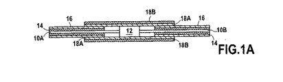
本発明では、図1Aと1Bの図に示されているように、接続12の導体ワイヤおよび/またはケーブル10Aと10Bの絶縁はもはや電気的含浸樹脂を付加することではなく、絶縁構造に基づいており、絶縁構造は導体ワイヤから外側に設けられている。
・導体ワイヤ上へ押し出される耐化学薬品性のポリマー、典型的にはポリテトラフルオロエチレン(PTFE)またはポリエーテルエーテルケトン(PEEK)から作られ、溶融温度を示さないか300℃よりも遥かに高い溶融温度を有する絶縁層14と、
・溶融可能なフッ化ポリマー、典型的には、導体ワイヤがさらされる温度(適用温度)よりも高い溶融温度、典型的には最大200℃であるが上記の絶縁層の溶融温度よりも遥かに低い温度である溶融温度を有するフッ化エチレンポリプロピレン(FEP)またはパーフルオロアルコキシ共重合体(PFA)により形成される絶縁層16。
The features and advantages of the present invention will become more apparent from the following description, given by way of illustration and not limitation, with reference to the accompanying drawings, in which:
In the present invention, as shown in the diagrams of FIGS. 1A and 1B, the insulation of the conductor wires and / or
• Made from a chemically resistant polymer that is extruded onto the conductor wire, typically polytetrafluoroethylene (PTFE) or polyetheretherketone (PEEK), showing no melting temperature or much higher than 300 ° C An insulating
A meltable fluorinated polymer, typically a melting temperature higher than the temperature to which the conductor wire is exposed (application temperature), typically up to 200 ° C., but far above the melting temperature of the insulating layer described above An insulating
以下「内部」絶縁として説明の中で示されている第1の絶縁層14は随意選択的な層であり、他方で以下「外部」絶縁と呼ぶ第2の絶縁層16は常に存在する。第1の絶縁層が存在してもしなくても、第2の絶縁層は常に前記第1の層上へ押し出されるか、そうでなければ導体ワイヤ上へ直接押し出される。対照的に、第1の絶縁層は押し出されてもよく、または特に大きい直径のケーブルでは幾つかの他の方法により単に配置されてもよい。
The
このタイプの絶縁は、磁気軸受けを含む産業応用で遭遇する非常に多くの環境において非常に良好な化学的安定性を示す利点を与える。種々の環境に関するこの化学的不活性により軸受けのコイルが接地電位から絶縁されることを保証され、これは200度程度の温度まで応用可能である。 This type of insulation provides the advantage of very good chemical stability in the vast number of environments encountered in industrial applications including magnetic bearings. This chemical inertness with respect to various environments ensures that the coil of the bearing is insulated from ground potential, which is applicable up to temperatures of the order of 200 degrees.
導体ワイヤ10A、10Bの外部絶縁層として溶融可能なフッ化ポリマーの使用は、外部層16を連結スリーブ18の類似の層18Aと共に溶融することにより導体ワイヤ間の漏れのない接続を実現することを可能にし、連結スリーブ18は接続と連結スリーブ18が接続されている導体ワイヤの端部をカバーしている。これを行うため、連結スリーブは圧力を2つの溶融可能な層へ適用する役目を行う熱収縮ポリマー18Bの外部層を有し、したがって連続的であり(溶融可能な絶縁物を含まない接続周囲のゾーンを充填する)、完全に気密および液密であり、それによって電気接続により構成される弱い点を限定する溶接20を形成する。2つの層は溶融可能な絶縁の層の溶融温度よりも高い温度へ加熱することにより溶融され、加熱素子として導体ワイヤを使用することが可能である。溶融は加圧された媒体における爆発に続いて爆発的減圧を生じる可能性がある接続中の任意の気泡または空洞を閉じ込めることを避けるために真空中で行われることができる。
The use of a meltable fluorinated polymer as the outer insulation layer of the
溶融可能ではない内部絶縁層は随意選択的であり、熱いとき外部絶縁層がクリープを受ける場合に絶縁の連続性を保証することが必要である。その理由で、その溶融温度は外部絶縁層の溶融温度よりも高くなければならない。 Inner insulating layers that are not meltable are optional, and it is necessary to ensure insulation continuity when the outer insulating layer undergoes creep when hot. For that reason, its melting temperature must be higher than the melting temperature of the outer insulating layer.
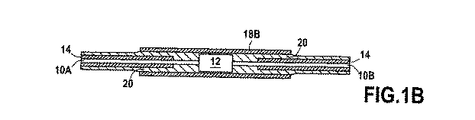
溶融可能な絶縁体の2つの層を共に溶接するこの漏れのない連結接続は、機械の他の接続、特に温度プローブの接続に対して特別な難点なしに一般化されることができ、ここでは前記接続はまた腐食性気体または潜在的に湿り気のある気体中で動作する機械において弱点を構成する。したがって図2Aと2Bに示されているように、温度プローブ22は2つの導体24A、24Bにより測定電子装置(図示せず)へ接続される。各導体は第1の絶縁層26と第2の絶縁層28を有し、プローブは溶融可能な絶縁体30Aの内部層と熱収縮ポリマー30Bの外部層とを具備する連結スリーブ30により包囲される。絶縁の内部層30Aの厚さは変化でき、温度プローブ周辺で充填される必要があるゾーンに適合されることができ、それによって加熱後、連続的で完全に漏れのない溶融可能な溶接32が得られる。
This leak-free connecting connection, which welds two layers of meltable insulator together, can be generalized without any special difficulties to other connections of the machine, in particular the connection of the temperature probe. The connection also constitutes a weak point in machines operating in corrosive or potentially humid gases. Thus, as shown in FIGS. 2A and 2B,
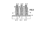
この漏れのない接続原理は、信号および/または電力が媒体にさらされる機械中に存在する加圧された媒体に出入りことを可能にする漏れのないブッシングを接続することにも応用されることができることも明白である。漏れのないブッシングと接触する溶融可能な絶縁層を使用することによって、流体の含浸による絶縁の損失は接触がある限り限定される。したがって図3に示されているように、漏れのないブッシング34、36、38の3つの接触部で伝送される信号は3つの導体40、42、44に直接接続される。各導体はそれぞれ第1の各絶縁層46、48、50、第2の各絶縁層で被覆され、それぞれ連結スリーブ52、54、56により包囲され、連結スリーブは熱収縮ポリマー52B、54B、56Bの外部層と溶融可能な絶縁の内部層とを具備し、溶融可能な絶縁体の内部層は加熱後、漏れのないブッシングの接触部をカバーする外部絶縁層と共に、連続的で完全に漏れのない溶融可能な溶接58を形成する役目を行う。
This leak-free connection principle can also be applied to connect leak-free bushings that allow signals and / or power to enter and exit the pressurized media present in the machine exposed to the media. It is clear that it can be done. By using a meltable insulating layer in contact with a leak-proof bushing, the loss of insulation due to fluid impregnation is limited as long as there is contact. Thus, as shown in FIG. 3, signals transmitted at the three contacts of the leak-
したがって本発明では、同じタイプの層と関連して溶融可能な絶縁層でカバーされる導体ワイヤの使用により、侵略的環境に対して良好な保護を行いながら、時間と人員と化学物質の管理を要する含浸作業を省略することが可能である。
以下に、本願出願時の特許請求の範囲に記載された発明を付記する。
[1]腐食性の気体又は液体にさらされる環境において漏れのない電気接続を実現するための電気接続部において、前記接続は、
・相互間またはコネクタ素子(12;22)と前記電気接続を形成するための少なくとも2つの導体(10A、10B;24A、24B;34、36、38、40、42、44)と、
・各前記導体上に形成され、前記環境の温度と予め定められたさらに高い温度との間に位置する温度で溶融可能なフッ化ポリマーから作られた外部絶縁層(16;28)と、
・前記導体を包囲し、熱収縮ポリマーの外部層(18B;30B;52B、54B、56B)と、前記環境の温度と前記予め定められたさらに高い温度との間に位置する温度で溶融可能な前記フッ化ポリマーの内部層(18A;30A)から作られた熱収縮スリーブ(18;30;52、54、56)とを具備し、
前記環境の温度よりも高く前記予め定められたさらに高い温度よりも低い温度へ加熱することにより前記導体の前記外部絶縁層と前記熱収縮スリーブの前記内部層とを溶融し、それによって連続的であり漏れのない制御された厚さの溶接部(20;32;58)を形成することを特徴とする電気接続部。
[2]前記導体の前記外部絶縁層と前記熱収縮スリーブの前記内部層はフッ化エチレンプロピレン(FEP)から作られていることを特徴とする前記[1]記載の電気接続部。
[3]前記導体の前記外部絶縁層はパーフルオロアルコキシ共重合体(PFA)から作られていることを特徴とする前記[1]記載の電気接続部。
[4]前記熱収縮スリーブの前記内部層は、連続的で完全に漏れのない溶接を得るために、変化し、接続のための前記素子周辺を充填するためのゾーンに適応される厚さであることができることを特徴とする前記[1]記載の電気接続部。
[5]さらに前記予め定められたさらに高い温度よりも高い温度に耐える内部絶縁層を各前記導体上に含んでいることを特徴とする電気接続部。
[6]前記導体の前記内部絶縁層はポリエーテルエーテルケトン(PEEK)から作られていることを特徴とする前記[5]記載の電気接続部。
[7]前記導体の前記内部絶縁層および前記熱収縮スリーブの前記外部層はポリテトラフルオロエチレン(PTFE)から作られていることを特徴とする前記[5]記載の電気接続部。
[8]前記環境の前記温度は200℃よりも高くはないことを特徴とする前記[1]記載の電気接続部。
[9]前記予め定められた温度は少なくとも300℃であることを特徴とする前記[1]または[5]記載の電気接続部。
[10]接続される前記素子はしたがってその環境に関して密封される温度プローブであることを特徴とする前記[1]乃至[9]のいずれか1つに記載の電気接続部。
[11]前記導体の1つは漏れのないブッシングのコンタクトであることを特徴とする前記[1]乃至[9]のいずれか1つに記載の電気接続部。
[12]前記導体は前記溶融期間中に加熱素子として使用されることを特徴とする前記[1]乃至[9]のいずれか1つに記載の電気接続部。
[13]電気モータ、磁気軸受け、磁気軸受け位置センサ、磁気軸受け速度センサの各装置における前記[1]乃至[9]のいずれか1つに記載の電気接続の使用。
Thus, the present invention provides time, personnel and chemical management while providing good protection against invasive environments by using a conductor wire covered with a meltable insulating layer in conjunction with the same type of layer. It is possible to omit the required impregnation work.
The invention described in the scope of claims at the time of filing the present application will be appended.
[1] In an electrical connection for realizing a leak-free electrical connection in an environment exposed to corrosive gas or liquid, the connection comprises:
At least two conductors (10A, 10B; 24A, 24B; 34, 36, 38, 40, 42, 44) for forming said electrical connection with each other or with the connector element (12; 22);
An outer insulating layer (16; 28) made of a fluorinated polymer formed on each said conductor and meltable at a temperature located between the temperature of said environment and a predetermined higher temperature;
-Surrounding the conductor and meltable at an outer layer of heat-shrinkable polymer (18B; 30B; 52B, 54B, 56B) and a temperature located between the temperature of the environment and the predetermined higher temperature A heat shrink sleeve (18; 30; 52, 54, 56) made from an inner layer (18A; 30A) of said fluorinated polymer;
The outer insulating layer of the conductor and the inner layer of the heat shrink sleeve are melted by heating to a temperature higher than the ambient temperature and lower than the predetermined higher temperature, thereby continuously Electrical connection characterized in that it forms a weld (20; 32; 58) of controlled thickness with no leakage.
[2] The electrical connection part according to [1], wherein the outer insulating layer of the conductor and the inner layer of the heat shrink sleeve are made of fluorinated ethylene propylene (FEP).
[3] The electrical connection part according to [1], wherein the outer insulating layer of the conductor is made of a perfluoroalkoxy copolymer (PFA).
[4] The inner layer of the heat shrink sleeve is varied to obtain a continuous and completely leak-free weld, with a thickness adapted to the zone for filling the periphery of the element for connection. The electrical connection part according to [1], wherein the electrical connection part can be.
[5] The electrical connection portion further comprising an internal insulating layer that can withstand a temperature higher than the predetermined higher temperature on each of the conductors.
[6] The electrical connection according to [5], wherein the inner insulating layer of the conductor is made of polyetheretherketone (PEEK).
[7] The electrical connection according to [5], wherein the inner insulating layer of the conductor and the outer layer of the heat shrink sleeve are made of polytetrafluoroethylene (PTFE).
[8] The electrical connection unit according to [1], wherein the temperature of the environment is not higher than 200 ° C.
[9] The electrical connection unit according to [1] or [5], wherein the predetermined temperature is at least 300 ° C.
[10] The electrical connection according to any one of [1] to [9], wherein the element to be connected is a temperature probe that is sealed with respect to its environment.
[11] The electrical connection part according to any one of [1] to [9], wherein one of the conductors is a bushing contact without leakage.
[12] The electrical connection part according to any one of [1] to [9], wherein the conductor is used as a heating element during the melting period.
[13] Use of the electrical connection according to any one of [1] to [9] in each device of an electric motor, a magnetic bearing, a magnetic bearing position sensor, and a magnetic bearing speed sensor.
Claims (12)
・相互間にまたはコネクタ素子(12;22)と前記電気接続部を形成するための少なくとも2つの導体(10A、10B;24A、24B;34、36、38、40、42、44)と、
・各前記導体上に形成され、前記環境の温度と予め定められた高い温度との間に位置する温度で溶融可能なフッ化ポリマーから作られた外部絶縁層(16;28)と、
・前記導体を包囲し、熱収縮ポリマーの外部層(18B;30B;52B、54B、56B)と、前記環境の温度と前記予め定められた高い温度との間に位置する温度で溶融可能な前記フッ化ポリマーの内部層(18A;30A)とから作られた熱収縮スリーブ(18;30;52、54、56)と、
を具備し、
前記環境の温度よりも高く且つ前記予め定められた高い温度よりも低い温度へ加熱することにより前記導体の前記外部絶縁層と前記熱収縮スリーブの前記内部層とを溶融し、それによって連続的であり漏れのない制御された厚さの溶接部(20;32;58)を形成し、
前記導体は前記溶融の期間中に加熱素子として使用される、ことを特徴とする電気接続部。 In the electrical connection for realizing the electrical connection leaktight in an environment exposed to corrosive gas or liquid, the electrical connections,
- inter or connector elements (12; 22) and said to form an electrical connection at least two conductors (10A, 10B; 24A, 24B ; 34,36,38,40,42,44) and,
· Each said formed on the conductor, outer insulating layer made of meltable fluoropolymer at a temperature located between high have the predetermined temperature and the temperature of the environment; (16 28),
- the conductor surrounding the external layer of a heat shrinkable polymer (18B; 30B; 52B, 54B , 56B) and, meltable at a temperature located between the temperature and the not high temperature predetermined for the environment inner layer of said fluorinated polymer and; (52,54,56 18;; 30) , (18A 30A) because made heat shrinkable sleeve
Comprising
Melted and said inner layer of said heat shrink sleeve and the outer insulating layer of the conductor by heating to a lower temperature than the high and the not high temperature predetermined than the temperature of the environment, continuously whereby by and weld leak-free controlled thickness to form a (20; 58; 32),
Electrical connection, characterized in that the conductor is used as a heating element during the melting period .
Applications Claiming Priority (2)
| Application Number | Priority Date | Filing Date | Title |
|---|---|---|---|
| FR1056072 | 2010-07-23 | ||
| FR1056072A FR2963154B1 (en) | 2010-07-23 | 2010-07-23 | ELECTRIC APPARATUS WITH SEALED CONNECTIONS AND METHOD OF MANUFACTURE |
Publications (2)
| Publication Number | Publication Date |
|---|---|
| JP2012028331A JP2012028331A (en) | 2012-02-09 |
| JP5774401B2 true JP5774401B2 (en) | 2015-09-09 |
Family
ID=43662055
Family Applications (1)
| Application Number | Title | Priority Date | Filing Date |
|---|---|---|---|
| JP2011161997A Active JP5774401B2 (en) | 2010-07-23 | 2011-07-25 | Appliance having a leak-free connection and manufacturing method |
Country Status (5)
| Country | Link |
|---|---|
| US (1) | US8927864B2 (en) |
| EP (1) | EP2410533B1 (en) |
| JP (1) | JP5774401B2 (en) |
| CA (1) | CA2746809C (en) |
| FR (1) | FR2963154B1 (en) |
Families Citing this family (7)
| Publication number | Priority date | Publication date | Assignee | Title |
|---|---|---|---|---|
| AU2013262460B2 (en) * | 2012-05-14 | 2016-11-03 | Next Wave Design Pty Ltd | Cable holder |
| FR2994021B1 (en) | 2012-07-27 | 2014-08-22 | Mecanique Magnetique Sa | ELECTRICAL CONNECTOR SEALED FOR MAGNETIC BEARINGS |
| US20160087502A1 (en) * | 2014-09-24 | 2016-03-24 | Baker Hughes Incorporated | Systems and Methods for Splicing Electrical Conductors in an ESP Motor |
| CN109904683B (en) * | 2018-12-29 | 2021-03-23 | 厦门广成精密工业有限公司 | Intelligent bathroom wire harness and processing technology thereof |
| US20220071693A1 (en) | 2020-09-10 | 2022-03-10 | Biosense Webster (Israel) Ltd. | Surface mounted electrode catheter |
| CN113746258B (en) * | 2021-07-31 | 2023-09-01 | 苏州百狮腾电气有限公司 | Magnetic levitation motor for testing by electromagnetic wire connection wire |
| CN114024166A (en) * | 2021-09-26 | 2022-02-08 | 浙江大华技术股份有限公司 | Cable assembly and method of installing cable assembly |
Family Cites Families (21)
| Publication number | Priority date | Publication date | Assignee | Title |
|---|---|---|---|---|
| US3451609A (en) * | 1967-08-24 | 1969-06-24 | Us Air Force | Heat shrinkable plastic soldering sleeve |
| US3582457A (en) * | 1967-12-19 | 1971-06-01 | Electronized Chem Corp | Heat shrinkable components with meltable insert liner |
| US3777048A (en) * | 1971-09-22 | 1973-12-04 | Kaiser Aluminium Chem Corp | Molding process for splicing cable and product formed thereby |
| US4801501A (en) * | 1986-08-28 | 1989-01-31 | Carlisle Corporation | Insulated conductor with multi-layer, high temperature insulation |
| JP2827236B2 (en) * | 1988-11-24 | 1998-11-25 | 住友電気工業株式会社 | Self-fusing insulated wire and its coil |
| JPH04334946A (en) * | 1991-05-08 | 1992-11-24 | Youyuu Tansanengata Nenryo Denchi Hatsuden Syst Gijutsu Kenkyu Kumiai | Bearing coil and sensor coil for high temperature magnetic bearing device |
| NO950846L (en) * | 1994-03-10 | 1995-09-11 | Atochem Elf Sa | Enveloped cables with improved flexibility and method of manufacture thereof |
| US5537742A (en) * | 1995-05-22 | 1996-07-23 | General Signal Corporation | Method for joining multiple conductor cables |
| JP3215301B2 (en) * | 1995-08-30 | 2001-10-02 | 株式会社山武 | Detecting element sealing structure and method of manufacturing the same |
| JPH10329216A (en) * | 1997-05-28 | 1998-12-15 | Nkk Corp | Self-heating type heat shrinkable tube |
| FR2826077B1 (en) | 2001-06-15 | 2003-09-19 | Mecanique Magnetique Sa | ACTIVE MAGNETIC BEARING WITH INTEGRATED SENSORS |
| CA2355972C (en) * | 2001-08-24 | 2009-11-17 | Shawcor Ltd. | Ionomer-insulated electrical connectors |
| JP2006349612A (en) * | 2005-06-20 | 2006-12-28 | Okazaki Mfg Co Ltd | Temperature sensor and manufacturing method |
| US7232955B1 (en) * | 2005-12-08 | 2007-06-19 | General Electric Company | Cable seals and methods of assembly |
| EP2126358A2 (en) * | 2007-03-07 | 2009-12-02 | Saint-Gobain Performance Plastics Corporation | Multi-layer tubes |
| US7679242B2 (en) * | 2007-10-03 | 2010-03-16 | Baker Hughes Incorporated | Shrink tube encapsulated magnet wire for electrical submersible motors |
| US7494289B1 (en) * | 2007-10-10 | 2009-02-24 | Schlumberger Technology Corporation | Optical fibre splice protector |
| JP5274575B2 (en) * | 2007-12-28 | 2013-08-28 | サン−ゴバン パフォーマンス プラスティックス コーポレイション | Reinforced tube |
| CA2658494A1 (en) * | 2009-03-13 | 2010-09-13 | Shawcor Ltd. | Apparatus for heating heat shrink sleeves |
| US8247050B2 (en) * | 2009-06-02 | 2012-08-21 | Integran Technologies, Inc. | Metal-coated polymer article of high durability and vacuum and/or pressure integrity |
| US8540295B2 (en) * | 2010-11-04 | 2013-09-24 | Lift-All Company, Inc. | Sling with protective covering |
-
2010
- 2010-07-23 FR FR1056072A patent/FR2963154B1/en not_active Expired - Fee Related
-
2011
- 2011-07-12 EP EP11173594A patent/EP2410533B1/en active Active
- 2011-07-19 CA CA2746809A patent/CA2746809C/en active Active
- 2011-07-22 US US13/188,702 patent/US8927864B2/en active Active
- 2011-07-25 JP JP2011161997A patent/JP5774401B2/en active Active
Also Published As
| Publication number | Publication date |
|---|---|
| CA2746809A1 (en) | 2012-01-23 |
| US8927864B2 (en) | 2015-01-06 |
| JP2012028331A (en) | 2012-02-09 |
| FR2963154A1 (en) | 2012-01-27 |
| US20120067640A1 (en) | 2012-03-22 |
| CA2746809C (en) | 2018-03-27 |
| EP2410533B1 (en) | 2013-03-06 |
| FR2963154B1 (en) | 2013-07-19 |
| EP2410533A1 (en) | 2012-01-25 |
Similar Documents
| Publication | Publication Date | Title |
|---|---|---|
| JP5774401B2 (en) | Appliance having a leak-free connection and manufacturing method | |
| US9660374B2 (en) | Sealed electrical connector for magnetic bearings | |
| US4319074A (en) | Void-free electrical conductor for power cables and process for making same | |
| CA2833528C (en) | Electrical submersible pump system having high temperature slot, end bell and phase-to-phase insulation | |
| US4532375A (en) | Heating device for utilizing the skin effect of alternating current | |
| JP5405949B2 (en) | Device for connection point between two high voltage cables | |
| US20120093667A1 (en) | Power Cable For High Temperature Environments | |
| US4436565A (en) | Method of making a heating device for utilizing the skin effect of alternating current | |
| JP2007312594A (en) | Connecting portion for optical cable-shielding layer | |
| KR20110082510A (en) | Electrical machine with dual insulated coil assembly | |
| US8133068B2 (en) | Current connection apparatus for tanks | |
| US20160087502A1 (en) | Systems and Methods for Splicing Electrical Conductors in an ESP Motor | |
| US4617449A (en) | Heating device for utilizing the skin effect of alternating current | |
| KR19990083592A (en) | A method for determining the presence of water in materials | |
| EP3859916A1 (en) | Cable termination and method of manufacture | |
| CA2201888A1 (en) | Electrical equipment | |
| KR20160129815A (en) | Electric machine and method for producing an electric machine | |
| JP6965623B2 (en) | Winding structure, coils, transformers and rotating machines | |
| JP2011045177A (en) | Stator, method of manufacturing the same, and rotary electric machine | |
| KR101184823B1 (en) | Cable connection structure for motor using in water and the connection method of the cable | |
| Rummel et al. | Insulation of the coil and bus bar ends during assemblyof W7-X | |
| JP2000260618A (en) | Coil for electric apparatus and manufacture thereof | |
| KR20220017435A (en) | Power Cable Termination System | |
| Pelissou et al. | Underground Medium-Voltage Cable Rejuvenation—Part III: Influence of Operating and Emergency Conditions | |
| WO2019079473A1 (en) | Mineral insulated power cables for electric motor driven integral compressors |
Legal Events
| Date | Code | Title | Description |
|---|---|---|---|
| A621 | Written request for application examination |
Free format text: JAPANESE INTERMEDIATE CODE: A621 Effective date: 20140528 |
|
| A977 | Report on retrieval |
Free format text: JAPANESE INTERMEDIATE CODE: A971007 Effective date: 20150218 |
|
| A131 | Notification of reasons for refusal |
Free format text: JAPANESE INTERMEDIATE CODE: A131 Effective date: 20150224 |
|
| A521 | Request for written amendment filed |
Free format text: JAPANESE INTERMEDIATE CODE: A523 Effective date: 20150512 |
|
| TRDD | Decision of grant or rejection written | ||
| A01 | Written decision to grant a patent or to grant a registration (utility model) |
Free format text: JAPANESE INTERMEDIATE CODE: A01 Effective date: 20150602 |
|
| A61 | First payment of annual fees (during grant procedure) |
Free format text: JAPANESE INTERMEDIATE CODE: A61 Effective date: 20150701 |
|
| R150 | Certificate of patent or registration of utility model |
Ref document number: 5774401 Country of ref document: JP Free format text: JAPANESE INTERMEDIATE CODE: R150 |
|
| R250 | Receipt of annual fees |
Free format text: JAPANESE INTERMEDIATE CODE: R250 |
|
| R250 | Receipt of annual fees |
Free format text: JAPANESE INTERMEDIATE CODE: R250 |
|
| R250 | Receipt of annual fees |
Free format text: JAPANESE INTERMEDIATE CODE: R250 |
|
| R250 | Receipt of annual fees |
Free format text: JAPANESE INTERMEDIATE CODE: R250 |
|
| R250 | Receipt of annual fees |
Free format text: JAPANESE INTERMEDIATE CODE: R250 |
|
| R250 | Receipt of annual fees |
Free format text: JAPANESE INTERMEDIATE CODE: R250 |