JP5773949B2 - Radiation monitoring device - Google Patents
Radiation monitoring device Download PDFInfo
- Publication number
- JP5773949B2 JP5773949B2 JP2012128713A JP2012128713A JP5773949B2 JP 5773949 B2 JP5773949 B2 JP 5773949B2 JP 2012128713 A JP2012128713 A JP 2012128713A JP 2012128713 A JP2012128713 A JP 2012128713A JP 5773949 B2 JP5773949 B2 JP 5773949B2
- Authority
- JP
- Japan
- Prior art keywords
- test
- input
- pulse
- count rate
- integrated value
- Prior art date
- Legal status (The legal status is an assumption and is not a legal conclusion. Google has not performed a legal analysis and makes no representation as to the accuracy of the status listed.)
- Active
Links
- 230000005855 radiation Effects 0.000 title claims description 178
- 238000012806 monitoring device Methods 0.000 title claims description 5
- 238000012360 testing method Methods 0.000 claims description 456
- 238000012544 monitoring process Methods 0.000 claims description 95
- 238000005259 measurement Methods 0.000 claims description 82
- 230000004044 response Effects 0.000 claims description 64
- 238000001514 detection method Methods 0.000 claims description 44
- 230000010354 integration Effects 0.000 claims description 19
- 230000008859 change Effects 0.000 claims description 17
- 238000000034 method Methods 0.000 claims description 17
- 230000008569 process Effects 0.000 claims description 17
- 230000003321 amplification Effects 0.000 claims description 9
- 238000003199 nucleic acid amplification method Methods 0.000 claims description 9
- 238000007493 shaping process Methods 0.000 claims description 8
- 230000005540 biological transmission Effects 0.000 claims description 6
- 230000005856 abnormality Effects 0.000 claims description 4
- 238000010998 test method Methods 0.000 claims description 4
- 238000012545 processing Methods 0.000 claims description 2
- 238000010586 diagram Methods 0.000 description 22
- 230000006870 function Effects 0.000 description 12
- 230000007423 decrease Effects 0.000 description 7
- 230000007704 transition Effects 0.000 description 7
- 230000015572 biosynthetic process Effects 0.000 description 6
- 238000003786 synthesis reaction Methods 0.000 description 6
- 230000000903 blocking effect Effects 0.000 description 5
- 230000003252 repetitive effect Effects 0.000 description 4
- 230000002194 synthesizing effect Effects 0.000 description 4
- 238000012790 confirmation Methods 0.000 description 3
- 238000000691 measurement method Methods 0.000 description 3
- 238000013459 approach Methods 0.000 description 2
- 238000012958 reprocessing Methods 0.000 description 2
- 238000004904 shortening Methods 0.000 description 2
- 239000002915 spent fuel radioactive waste Substances 0.000 description 2
- 238000006243 chemical reaction Methods 0.000 description 1
- 230000001186 cumulative effect Effects 0.000 description 1
- 230000006872 improvement Effects 0.000 description 1
- 238000002955 isolation Methods 0.000 description 1
- 230000010355 oscillation Effects 0.000 description 1
Images


Classifications
-
- G—PHYSICS
- G01—MEASURING; TESTING
- G01T—MEASUREMENT OF NUCLEAR OR X-RADIATION
- G01T1/00—Measuring X-radiation, gamma radiation, corpuscular radiation, or cosmic radiation
- G01T1/16—Measuring radiation intensity
- G01T1/18—Measuring radiation intensity with counting-tube arrangements, e.g. with Geiger counters
-
- G—PHYSICS
- G01—MEASURING; TESTING
- G01T—MEASUREMENT OF NUCLEAR OR X-RADIATION
- G01T7/00—Details of radiation-measuring instruments
-
- G—PHYSICS
- G01—MEASURING; TESTING
- G01T—MEASUREMENT OF NUCLEAR OR X-RADIATION
- G01T7/00—Details of radiation-measuring instruments
- G01T7/12—Provision for actuation of an alarm
- G01T7/125—Alarm- or controlling circuits using ionisation chambers, proportional counters or Geiger-Mueller tubes, also functioning as UV detectors
Landscapes
- Physics & Mathematics (AREA)
- Health & Medical Sciences (AREA)
- Life Sciences & Earth Sciences (AREA)
- General Physics & Mathematics (AREA)
- High Energy & Nuclear Physics (AREA)
- Molecular Biology (AREA)
- Spectroscopy & Molecular Physics (AREA)
- Measurement Of Radiation (AREA)
Description
この発明は、原子炉施設、使用済燃料再処理施設等の放出管理あるいは放射線管理に用いられる放射線監視装置に関するものである。 The present invention relates to a radiation monitoring apparatus used for emission management or radiation management of a nuclear reactor facility, a spent fuel reprocessing facility, or the like.
原子炉施設、使用済燃料再処理施設等で使用される放射線監視装置は、放射線を検出する検出器と、放射線検出器からの検出信号パルスから計数率を測定する測定部を備えた複数チャンネルの放射線モニタと、個々の放射線モニタにテストパルスを入力するテストパルス発生部と、テストパルスの周波数を制御するとともに、放射線モニタの測定部における検出信号パルスとテストパルスの入力切換を行うテストパルス制御部を備えた試験装置から構成される。試験装置は、放射線モニタの測定部の入力切換スイッチを制御して検出信号パルスからテストパルスに入力を切り換え、入力に対する出力の直線性を測定する入出力応答テスト、テストパルスの周波数をランプ状に変化させ警報動作点の計数率から警報動作精度を確認する警報テストを行って個々の放射線モニタの健全性を確認している。 A radiation monitoring device used in a nuclear reactor facility, spent fuel reprocessing facility, etc. is a multi-channel equipped with a detector that detects radiation and a measurement unit that measures a count rate from detection signal pulses from the radiation detector. Radiation monitor, test pulse generator for inputting a test pulse to each radiation monitor, and test pulse controller for controlling the frequency of the test pulse and switching the input of the detection signal pulse and the test pulse in the measurement unit of the radiation monitor It is comprised from the testing apparatus provided with. The test equipment switches the input from the detection signal pulse to the test pulse by controlling the input changeover switch of the measurement part of the radiation monitor, the input / output response test to measure the linearity of the output with respect to the input, the frequency of the test pulse in a ramp The soundness of each radiation monitor is confirmed by performing an alarm test to confirm the alarm operation accuracy from the count rate of the alarm operation point.
計数率指示応答の精度及び警報動作の精度の確認では、試験装置は測定部にテストパルスを入力し、テスト項目に応じてテストパルス発生部のテストパルスの発信周波数をステップ状あるいはランプ状に変化させる。なお、テスト期間中は、放射線監視装置から外部へ警報が出力されないように、必要に応じてテスト開始前に警報をブロックし、テスト終了後はブロックを解除する。 In confirming the accuracy of the count rate instruction response and the accuracy of the alarm operation, the test device inputs a test pulse to the measurement unit, and the test pulse generation frequency of the test pulse generator changes in a step or ramp shape according to the test item. Let During the test period, the alarm is blocked before the start of the test as necessary so that the alarm is not output from the radiation monitoring apparatus to the outside, and the block is released after the end of the test.
各放射線モニタは、測定した計数率を必要に応じて線量率等の工学値に変換して放射線量を求め、通常のバックグラウンドレベルより高い放射線量レベルに高警報が設定され、上記施設の管理エリアの線量率またはプロセス系統の放射能(計数率に比例)の異常に対して高警報を発信して運転員に報知するとともに、自動で必要な系統隔離を行うことができる。また、通常のバックグラウンドレベルより低い放射線量レベルに低警報が設定され、放射線モニタの故障による検出信号喪失あるいは検出信号の計数率の低下に対して低警報を発信して運転員に報知する。 Each radiation monitor calculates the radiation dose by converting the measured count rate into engineering values such as a dose rate as necessary, and a high alarm is set at a radiation dose level higher than the normal background level. A high warning can be issued to notify the operator of abnormalities in area dose rate or process system radioactivity (proportional to the count rate), and necessary system isolation can be performed automatically. Also, a low alarm is set at a radiation dose level lower than the normal background level, and a low alarm is issued to notify the operator of a loss of detection signal due to a failure of the radiation monitor or a decrease in the detection signal count rate.
一方、放射線モニタで測定された計数率は統計的に変動するため、標準偏差が一定となるように計数率に応じて自動的に時定数を制御することにより標準偏差が一定となるように計数率が測定されて測定精度を維持している。また、測定部は、計数率が10cpm程度から107cpm程度までの広いレンジをカバーして測定することが求められ、レンジ切り換えに伴う不連続性をなくすために、広いレンジをレンジ切り換えなしで自動的に標準偏差が一定となるように、アップダウンカウンタを用いて負帰還回路を構成し、高速動作が可能な計数率測定方式が採用されている。 On the other hand, since the count rate measured by the radiation monitor fluctuates statistically, the time constant is automatically controlled according to the count rate so that the standard deviation is constant. The rate is measured and the measurement accuracy is maintained. In addition, the measurement unit is required to measure over a wide range of counting rates from about 10 cpm to about 10 7 cpm, and in order to eliminate discontinuities associated with range switching, the wide range can be switched without range switching. A count rate measurement method is employed in which a negative feedback circuit is configured using an up / down counter so that the standard deviation is automatically constant, and high-speed operation is possible.
このアップダウンカウンタを用いた計数率測定方式は、加算入力と減算入力の差分の積算値を一定周期で読み取って計数率を演算するもので、加算入力は、放射線検出器から測定部に入力された検出信号パルスを増幅して波高弁別したデジタルパルスであり、減算入力は、積算値に基づきクロックパルスを分周・周波数合成して生成されたデジタルパルスであり、特に高計数率まで精度よく測定できることが特徴である。 This counting rate measurement method using an up / down counter calculates the counting rate by reading the integrated value of the difference between the addition input and the subtraction input at a constant period. The addition input is input from the radiation detector to the measurement unit. This is a digital pulse obtained by amplifying the detected signal pulse and discriminating the pulse height, and the subtraction input is a digital pulse generated by dividing and frequency synthesizing the clock pulse based on the integrated value. It is a feature that can be done.
アップダウンカウンタを用いた計数率測定は計数率が時定数で応答するため、テストパルスをデカード毎に入力して入力に対する出力の直線性を測定する入出力応答テスト及びテストパルスを入力して警報動作を確認する警報テストに時間がかかる。このため、テスト項目毎にテストパルスをステップ状に変化させるステップ入力とランプ状に変化させるランプ入力を組み合わせて、ステップ状変化の大きさとステップの継続時間を最適化するとともにランプ信号の傾きと継続時間を最適化して予め設定しておくことにより、入力するテストパルスをステップ入力で目標値に急接近させ、ランプ入力で目標値にゆるやかに接近させるように、テストパルスを制御することで試験時間を短縮する発明が開示されている(例えば、特許文献1)。
また、テストパルス制御部が、放射線モニタの計数率の今回値と目標値から判断し、加算入力または減算入力のどちらかで動作するようにテストパルスの入力を切換制御する発明が開示されている(例えば、特許文献2)。
Count rate measurement using an up / down counter responds with a time constant, so input / output response tests that measure the linearity of the output against the input by inputting a test pulse for each card and alarms by inputting the test pulse The alarm test to confirm the operation takes time. Therefore, the step input that changes the test pulse stepwise for each test item and the ramp input that changes the ramp shape are combined to optimize the magnitude of the step change and the duration of the step, as well as the slope and duration of the ramp signal. By optimizing the time and setting in advance, the test time is controlled by controlling the test pulse so that the test pulse to be input approaches the target value quickly by step input and gradually approaches the target value by ramp input. Has been disclosed (for example, Patent Document 1).
Further, an invention is disclosed in which the test pulse control unit judges from the current value and the target value of the count rate of the radiation monitor and switches and controls the input of the test pulse so as to operate with either the addition input or the subtraction input. (For example, patent document 2).
特許文献1開示発明では、短時間で目標値に到達させるテストパルスの制御が難しく、試験時間の短縮の要求に対して更なる改善が求められている。特に、低計数率のテスト項目は、時定数が計数率に反比例しかつ積算値が時定数で変化するのを待つ必要がありテストに長時間を要するという問題があった。
特許文献2開示発明でも、特に、低計数率のテスト項目は、時定数が計数率に反比例しかつ積算値が時定数で低下するのを待つ必要がありテストに長時間を要するという問題があった。
この発明は、上記のような問題を解決するためになされたものであり、特に低計数率のテスト項目において、試験時間を削減できる放射線監視装置を提供することを目的とする。
In the invention disclosed in
Even in the invention disclosed in
The present invention has been made to solve the above-described problems, and an object of the present invention is to provide a radiation monitoring apparatus that can reduce the test time particularly in a low count rate test item.
この発明に係る放射線監視装置は、放射線を測定する放射線モニタと、放射線モニタのテストを行う試験装置とから構成され、放射線モニタは、放射線検出器と、放射線検出器の検出信号パルスから計数率を測定する測定部を備え、試験装置は、テストパルスを発生するテストパルス発生部と、テストパルスの発信周波数(繰り返し周波数)を制御すると共に、測定部の測定モードとテストモードを切り換える切換信号を発生するテストパルス制御部を備え、測定部は、検出信号パルスを増幅すると共に波形を整形するパルス増幅部と、パルス増幅部の出力パルスからノイズを弁別除去してデジタルパルスを出力するノイズ弁別除去器と、デジタルパルスを加算入力に入力し、フィードバックパルスを減算入力に入力し、両者の差を積算した積算値を出力するアップダウンカウンタと、積算値からフィードバックパルスを発生する周波数合成回路と、アップダウンカウンタに対し計数時の重み付け指定する積算制御回路と、積算値を入力して計数率を算出する演算部と、テストパルス制御部からの切換信号によりパルス増幅部の入力またはアップダウンカウンタの加算入力および減算入力を切り換える入力切換手段と、テストパルス制御部からの設定積算値信号により、アップダウンカウンタの積算値を強制的にスタート計数率に対応する値に設定する積算値設定回路とを備えたものである。 A radiation monitoring apparatus according to the present invention includes a radiation monitor that measures radiation and a test apparatus that performs a test of the radiation monitor. The radiation monitor calculates a count rate from a radiation detector and a detection signal pulse of the radiation detector. The measuring device is equipped with a measuring unit that measures the test pulse generation unit that generates the test pulse and the switching signal for switching between the measurement mode and the test mode of the measuring unit while controlling the test pulse transmission frequency (repetition frequency). A test pulse control unit that amplifies the detection signal pulse and shapes the waveform, and a noise discrimination remover that discriminates and removes noise from the output pulse of the pulse amplification unit and outputs a digital pulse The digital pulse is input to the addition input, the feedback pulse is input to the subtraction input, and the difference between the two is integrated. An up / down counter that outputs a calculated value, a frequency synthesizer circuit that generates a feedback pulse from the integrated value, an integration control circuit that designates weighting at the time of counting for the up / down counter, and an integrated value that is input to calculate a count rate An arithmetic switching unit, input switching means for switching the input of the pulse amplification unit or the addition input and subtraction input of the up / down counter by the switching signal from the test pulse control unit, and the up / down counter by the set integrated value signal from the test pulse control unit And an integrated value setting circuit for forcibly setting the integrated value to a value corresponding to the start count rate.
この発明に係る放射線監視装置は、放射線を測定する放射線モニタと、放射線モニタのテストを行う試験装置とから構成され、放射線モニタは、放射線検出器と、放射線検出器の検出信号パルスから計数率を測定する測定部を備え、試験装置は、テストパルスを発生するテストパルス発生部と、テストパルスの発信周波数(繰り返し周波数)を制御すると共に、測定部の測定モードとテストモードを切り換える切換信号を発生するテストパルス制御部を備え、測定部は、検出信号パルスを増幅すると共に波形を整形するパルス増幅部と、パルス増幅部の出力パルスからノイズを弁別除去してデジタルパルスを出力するノイズ弁別除去器と、デジタルパルスを加算入力に入力し、フィードバックパルスを減算入力に入力し、両者の差を積算した積算値を出力するアップダウンカウンタと、積算値からフィードバックパルスを発生する周波数合成回路と、アップダウンカウンタに対し計数時の重み付け指定する積算制御回路と、積算値を入力して計数率を算出する演算部と、テストパルス制御部からの切換信号によりパルス増幅部の入力またはアップダウンカウンタの加算入力および減算入力を切り換える入力切換手段と、テストパルス制御部からの設定積算値信号により、アップダウンカウンタの積算値を強制的にスタート計数率に対応する値に設定する積算値設定回路とを備えたものであるため、特に低計数率のテスト項目において、試験時間を削減できる放射線監視装置を提供することができる。 A radiation monitoring apparatus according to the present invention includes a radiation monitor that measures radiation and a test apparatus that performs a test of the radiation monitor. The radiation monitor calculates a count rate from a radiation detector and a detection signal pulse of the radiation detector. The measuring device is equipped with a measuring unit that measures the test pulse generation unit that generates the test pulse and the switching signal for switching between the measurement mode and the test mode of the measuring unit while controlling the test pulse transmission frequency (repetition frequency). A test pulse control unit that amplifies the detection signal pulse and shapes the waveform, and a noise discrimination remover that discriminates and removes noise from the output pulse of the pulse amplification unit and outputs a digital pulse The digital pulse is input to the addition input, the feedback pulse is input to the subtraction input, and the difference between the two is integrated. An up / down counter that outputs a calculated value, a frequency synthesizer circuit that generates a feedback pulse from the integrated value, an integration control circuit that designates weighting at the time of counting for the up / down counter, and an integrated value that is input to calculate a count rate An arithmetic switching unit, input switching means for switching the input of the pulse amplification unit or the addition input and subtraction input of the up / down counter by the switching signal from the test pulse control unit, and the up / down counter by the set integrated value signal from the test pulse control unit Since the integrated value setting circuit forcibly sets the integrated value to a value corresponding to the start count rate is provided, a radiation monitoring apparatus capable of reducing the test time is provided, particularly in a low count rate test item. be able to.
実施の形態1.
実施の形態1は、放射線検出器と測定部からなる放射線モニタと試験装置を備える放射線監視装置において、測定部のアップダウンカウンタの積算値を強制的に設定する積算値設定回路を設け、テストモードにおいて、積算値設定回路によりアップダウンカウンタの積算値をスタート計数率に対応する値に設定した後、テストを実行するように構成した放射線監視装置に関するものである。
以下、本願発明の実施の形態1の構成、動作について、放射線監視装置のシステム構成図である図1、試験時の応答説明図である図2に基づいて説明する。
Hereinafter, the configuration and operation of the first embodiment of the present invention will be described based on FIG. 1 which is a system configuration diagram of a radiation monitoring apparatus and FIG. 2 which is a response explanatory diagram at the time of a test.
まず、放射線監視装置1の構成を説明し、次に機能、動作を説明する。
図1において、放射線監視装置1は、放射線を測定する放射線モニタ2と、放射線モニタ2のテストを行う試験装置3から構成されている。
放射線モニタ2は、放射線を検出して検出信号パルスを出力する放射線検出器4と、検出信号パルスを入力して計数率を測定する測定部5から構成されている。
試験装置3は、テストパルスを発生するテストパルス発生部6と、テストパルス発生部6から出力されるテストパルスの発信周波数を制御するとともに測定部5の入力を切り換えるテストパルス制御部7から構成されている。
First, the configuration of the
In FIG. 1, the
The
The
測定部5の放射線を測定する機能部分は、パルス増幅部11、ノイズ弁別除去器12、アップダウンカウンタ13、周波数合成回路14、積算値設定回路15、積算制御回路16、演算部17、および操作部18から構成されている。アップダウンカウンタ13は、ノイズ弁別除去器12からの信号が入力される加算入力13aおよび周波数合成回路14からのフィードバックパルスが入力される減算入力13bを有する。また、操作部18は、表示機能部と操作機能部を有する。
測定部5は、試験時に放射線検出器4からの検出信号と試験用のテストパルスを切り換えるために、例えば3ポジションを有する第1の切換スイッチ19と、アップダウンカウンタ13の減算入力13bへ入力される周波数合成回路14からの信号を切り換える2ポジションを有する第2の切換スイッチ20を備える。なお、実施の形態1において、本発明の入力切換手段は、第1の切換スイッチ19と第2の切換スイッチ20が対応する。
The functional part for measuring the radiation of the
The measuring
次に、放射線監視装置1の試験時の機能、動作を中心に説明する。
測定部5において、第1の切換スイッチ19は、テストパルス制御部7からの切換信号により、放射線検出器4からの検出信号パルス入力、入力断(遮断)、およびテストパルス発生部6からのテストパルス入力のいずれかに切り換える。以下の説明では、各ポジションを「検出信号」、「遮断」、「テスト信号」と記載する。
テストパルス発生部6において、出力されるテストパルスはデジタルパルスであり、その発信周波数すなわち繰り返し周波数はテストパルス制御部7からの制御信号で制御される。このテストパルスは、テストパルス発生部6または測定部5で、例えば微分して波形整形され、検出パルスの模擬パルスとして第1の切換スイッチ19に入力される。
Next, functions and operations during the test of the
In the
In the
測定部5において、第1の切換スイッチ19から入力された検出信号パルスまたはテストパルスは、パルス増幅部11で増幅されるとともに、重畳する高周波ノイズが除去され、波形整形される。ノイズ弁別除去器12は、増幅・整形された検出信号パルスについて、例えば波高電圧レベルが設定された範囲内にある場合にデジタルパルスを出力し、その範囲を逸脱した場合にノイズとして除去する。
In the
アップダウンカウンタ13は、ノイズ弁別除去器12から出力されたデジタルパルスを加算入力13aに入力し、後述するフィードバックパルスを減算入力13bに入力し、両者の差を積算した積算値を出力する。
周波数合成回路14は、アップダウンカウンタ13の出力である積算値を入力して、この積算値に基づき、後述の演算部17から入力されるクロックパルスを分周・周波数合成して、フィードバックパルス(デジタルパルス)を生成する。周波数合成回路14は、このフィードバックパルスをアップダウンカウンタ13の減算入力13bに出力する。
積算制御回路16はアップダウンカウンタ13が計数する時の後述する重み付けを行う。
The up / down counter 13 inputs the digital pulse output from the
The frequency synthesizing circuit 14 receives the integrated value that is the output of the up / down
The
第2の切換スイッチ20は、アップダウンカウンタ13の減算入力13bへ周波数合成回路14からのフィードバックパルスを入力する(通過させる)か、入力断(遮断)にするかを切り換えるもので、テストパルス制御部7からの切換信号で切り換えられる。以下の説明では、各ポジションを「通過」、「遮断」と記載する。
The
演算部17は、アップダウンカウンタ13から出力された積算値を入力し、積算値に基づき計数率を演算して、必要に応じて線量率等の工学値に変換する。演算部17は、得られた計数率または工学値を、例えば警報テストの場合、これらの警報設定値と比較して、警報発生状態かどうかを判定して高警報及び低警報を計数率または工学値とともに出力する。
なお、工学値は計数率に単位変換の定数を乗じたものであるので、以後、演算部17の出力が計数率の場合で説明する。
高警報は、例えば、放出管理許容レベルに基づき通常バックグラウンドより高いレベルに設定される。低警報は、例えば、放射線検出器4の故障による検出信号パルスの喪失または検出信号パルスの減少を検知するために、通常バックグラウンドより低いレベルに設定される。
The
Since the engineering value is obtained by multiplying the count rate by a constant for unit conversion, the following description will be made on the case where the output of the
The high alarm is set to a level higher than the normal background based on the emission management allowable level, for example. The low alarm is normally set to a level lower than the background in order to detect, for example, the loss of the detection signal pulse or the decrease in the detection signal pulse due to the failure of the
操作部18は、表示機能部で演算部17からの出力を表示するとともに、例えばタッチパネルを有する操作機能部で試験の操作および試験の手順、設定値の変更を行える。この操作部18での操作に基づき、テストパルス制御部7からの設定積算値信号は演算部17経由で積算値設定回路15に出力され、積算値設定回路15は、アップダウンカウンタ13の積算値を強制的に後述するスタート計数率に対応する値である設定積算値に置き換える。すなわち、積算値設定回路15は、テストパルス制御部7からの設定積算値信号により、アップダウンカウンタ13の積算値を強制的にスタート計数率に対応する値に設定する。この動作により、演算部17から出力される計数率は直ちに設定積算値に対応する計数率、すなわち当該テストのスタート計数率に変化する。なお、操作機能部の操作および試験の手順の設定等の機能はテストパルス制御部に備えてもよい。
The
放射線モニタ2は、測定モードとテストモードの2つのモードを備えており、いずれかのモードを選択して動作させる。テストパルス制御部7は、放射線モニタ2の測定部5の演算部17にアクセスしてモードを選択し、演算部17経由で第1の切換スイッチ19及び第2の切換スイッチ20の入力切換を行う。
The radiation monitor 2 has two modes, a measurement mode and a test mode, and is operated by selecting one of the modes. The test
ここで、アップダウンカウンタ13を使用した計数率の測定方法の概要を説明する。
演算部17から得られる計数率は統計的に変動するため、所定の精度で測定するには、次式のように標準偏差σが一定となるように計数率nに基づき時定数τを制御して測定するようになっている。
σ=1/(2nτ)1/2 (1)
τ=1/(2nσ2) (2)
Here, an outline of a counting rate measurement method using the up / down counter 13 will be described.
Since the count rate obtained from the
σ = 1 / (2nτ) 1/2 (1)
τ = 1 / (2nσ 2 ) (2)
アップダウンカウンタ13において、加算入力13aにはノイズ弁別除去器12から出力されたデジタルパルスが入力される。減算入力13bには周波数合成回路14のフィードバックパルスが入力され、加算入力13aに入力されるデジタルパルスの周波数FINと減算入力13bに入力されるフィードバックパルスの周波数FBが等しくなった平衡状態で、加算入力と減算入力の差を積算して出力される積算値Mは安定する。
In the up / down
平衡状態において、アップダウンカウンタ13の加算入力13aに入力されるデジタルパルスの周波数FINは、演算部17で求めた計数率n、および減算入力13bの周波数
FB(M)に等しくなる。デジタルパルスの周波数FINは、標準偏差σと積算値Mに基づいて次式のように演算され、FB(M)およびnは、次式のようにFINに平衡するように時定数(τ)の一次遅れで追従して応答する。
FIN=FB(M)=n=eγM=2γM/ln2 (3)
γ=2σ2=(1/nτ)=2−λ・ln2 (4)
β=11−λ (5)
ここで、γは重み付け計数の関係因子、βおよびλは零または正の整数である。
In the equilibrium state, the frequency F IN of the digital pulse input to the
F IN = F B (M) = n = e γM = 2 γM / ln2 (3)
γ = 2σ 2 = (1 / nτ) = 2 −λ · ln2 (4)
β = 11−λ (5)
Here, γ is a weighting factor and β and λ are zero or positive integers.
(4)式において、λを例えば11、9、7、5とすると、(1)式から標準偏差σはそれぞれ1.3%、2.6%、5.2%、10.4%となる。(4)式でλが11の時を標準にすると、λが9、7、5の時、γはそれぞれ22倍、24倍、26倍となる。
(1)式から、標準偏差σはそれぞれ21倍、22倍、23倍となる。(2)式から、時定数τはそれぞれ2−2倍、2−4倍、2−6倍となる。
(3)式に示すように、nが一定の状態でγを2β倍にすると、積算値Mは2−β倍の重み付けで応答する。すなわち、アップダウンカウンタ13の加算入力13aにノイズ弁別除去器12からデジタルパルスが1個入力されると、積算値Mは2βで重み付けされて加算計数する。一方、アップダウンカウンタ13の減算入力13bに周波数合成回路14からデジタルパルスが1個入力されると、積算値Mは2βで重み付けされて減算計数する。結果として、積算値Mは、加算計数と減算計数の差の積算値Nに2βを掛け算した値になる。
In the equation (4), when λ is 11, 9, 7, 5 for example, the standard deviation σ is 1.3%, 2.6%, 5.2%, 10.4% from the equation (1), respectively. . (4) If λ is the standard time of 11 in formula, when λ is 9,7,5, gamma respectively 2 twice, 2 four times, and 2 six times.
(1) from equation 2 1 times the standard deviation σ, respectively, 2 doubles, and 2 3 times. (2) from equation 2 -2 times the time constant τ, respectively, 2 -4 times, a 2-6 fold.
(3) As shown in equation, when n is the 2 beta double the γ in a constant state, the integrated value M responds with 2-beta fold weighting. That is, when the digital pulse from the noise discriminator remover 12 to a summing
βは0または正の整数で、(5)式のようにλが11、9、7、5の時、βとしてそれぞれ0、2、4、6が与えられる。例えば、λが11の時は1パルスの入力に対して1カウントが加算または減算される。λが9の時は、1パルスの入力に対して4カウントが加算または減算される。 β is 0 or a positive integer. When λ is 11, 9, 7, 5 as shown in the equation (5), 0, 2, 4, 6 are given as β, respectively. For example, when λ is 11, one count is added to or subtracted from one pulse input. When λ is 9, 4 counts are added to or subtracted from one pulse input.
したがって、試験に際し、操作部18において、標準偏差σを1.3%、2.6%、5.2%、10.4%から選定して設定すると、標準偏差σに対応するβが0、2、4、6から決定され、積算制御回路16はアップダウンカウンタ13が計数する際の1パルス入力当たりの重み2βを設定し、アップダウンカウンタ13は、積算制御回路16で設定された2βに基づき、1、4、16、64の対応する値で重み付けして計数する。
Therefore, when the standard deviation σ is selected and set from 1.3%, 2.6%, 5.2%, 10.4% in the
次に、放射線モニタ2を測定モードからテストモードに切り換えて、テストパルスを入力する場合のテストパルス制御部7の制御動作を説明する。
テストパルス制御部7において、例えばある計数率の指示精度を確認する目的のテスト項目である指示精度テストの場合を説明する。「指示精度テスト」のボタンを選択し、テストポイントの計数率を入力すると、テストパルス制御部7は、放射線モニタ2の測定部5の演算部17にアクセスしてテスト中警報を発信させる。次に、放射線モニタ2をテストモード状態にし、警報ブロックを「する」「しない」の選択ボタンのどちらかを選択すると、第1の切換スイッチ19の切換が可能な状態になる。さらに、テストパルス制御部7は、演算部17を経由して、第1の切換スイッチ19を「検出信号」から「遮断」ポジションに切り換えるとともに、第2の切換スイッチ20を「通過」から「遮断」ポジションに切り換える。
次に、テストパルス制御部7は、演算部17を経由して、積算値設定回路15に設定積算値信号を出力して、アップダウンカウンタ13の積算値を強制的にスタート計数率に対応する値の設定積算値Msに置き換える。
続いて、テストパルス制御部7は、第1の切換スイッチ19を「遮断」から「テスト信号」ポジションに切り換え、第2の切換スイッチ20を「遮断」から「通過」ポジションに切り換える。
この状態で、アップダウンカウンタ13の加算入力13aにはテストパルスが入力され、減算入力13bにはフィードバックパルスが入力されて、試験が開始される。
試験を終了する場合は、逆の順序で制御動作する。
Next, the control operation of the
In the
Next, the test
Subsequently, the
In this state, the test pulse is input to the
When the test is terminated, the control operation is performed in the reverse order.
指示精度テストにおいて積算値設定回路15からアップダウンカウンタに入力される設定積算値は、スタート計数率に対応する値であり、スタート計数率はテストポイントの計数率に合わせるようにしており、(6)式から演算される。
Ms=ln(n)/γ (6)
The set integrated value input from the integrated
Ms = ln (n) / γ (6)
テストパルス制御部7は、テストポイントの計数率を目標計数率としてテストパルス発生部6を制御することにより、目標計数率に対応する繰り返し周波数のテストパルスがステップ状に出力される。
The test
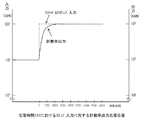
次に、試験時の応答動作を説明する。なお、図2(a)は、目標計数率>直前計数率の場合であり、図2(b)は、目標計数率<直前計数率の場合である。
図2は、指示精度テストにおける放射線モニタ2のテスト入力に対する計数率の応答を示すもので、図において、aはテストポイント、スタート計数率、目標計数率であり、3者を同じとすることにより、測定状態の計数率から目標計数率に至る時定数による応答時間を省略できる。計数率出力cは、テストパルス入力の繰り返し周波数bに対して、デジタル演算誤差だけシーソーのように上下にゆらいだ応答を示す。テストパルス制御部7は、演算部17から決められた演算周期数の計数率データを入力して、プラスマイナスの最大ゆらぎを偏差とし、目標計数率を基準に精度を求め、テストデータとして保管する。テストデータは、操作部18で表示させて見ることができると共に、モバイルメモリーに取り出すこともできる。演算誤差のゆらぎは、デジタル誤差が最大±2デジット加算されて、長い場合でも0、+1、+2、+1、0、−1、−2、−1の各デジット順で出力されることが考えられるので、8演算周期以上のデータを収集すれば最大と最小の偏差をもれなく評価できる。
従来の放射線監視装置では、試験時間が測定部5の時定数に依存するため、特に低計数率のテスト項目に対し、時間がかかっていた。しかし、本実施の形態1の放射線監視装置1では、強制的に設定計数率からスタートするため、試験時間が時定数依存せず、試験時間を大幅に短縮できる。
Next, the response operation during the test will be described. 2A shows the case where the target count rate> the previous count rate, and FIG. 2B shows the case where the target count rate <the previous count rate.
FIG. 2 shows the response of the count rate to the test input of the radiation monitor 2 in the indication accuracy test. In the figure, a is a test point, a start count rate, and a target count rate. The response time due to the time constant from the count rate in the measurement state to the target count rate can be omitted. The count rate output c shows a response that fluctuates up and down like a seesaw by a digital calculation error with respect to the repetition frequency b of the test pulse input. The test
In the conventional radiation monitoring apparatus, since the test time depends on the time constant of the
実施の形態1では、試験時において、試験装置3のテストパルス制御部7から測定部5の第1の切換スイッチ19および第2の切換スイッチ20の切り換え指示を演算部17経由としているが、演算部17を経由せず、直接切り換え操作する構成とすることもできる。
In the first embodiment, during the test, the switching instruction of the
以上説明したように、実施の形態1に係る放射線監視装置は、放射線検出器と測定部からなる放射線モニタと試験装置を備える放射線監視装置において、測定部のアップダウンカウンタの積算値を強制的に設定する積算値設定回路を設け、テストモードにおいて、積算値設定回路によりアップダウンカウンタの積算値を設定積算値に設定した後、テストを実行するように構成したので、テストポイントの計数率と同じ値のスタート計数率から指示精度テストを開始できるようになり、測定状態の計数率から目標計数率に至る時定数による応答時間を省略できので、特に低計数率のテスト項目において、試験時間を大幅に削減できる。
As described above, the radiation monitoring apparatus according to
実施の形態2.
実施の形態2の放射線監視装置は、実施の形態1の放射線監視装置の構成の内、アップダウンカウンタの加算入力に入力される検出信号とテスト信号を切り換える切換スイッチの構成を変更したものである。
The radiation monitoring apparatus according to the second embodiment is obtained by changing the configuration of the changeover switch that switches between the detection signal and the test signal input to the addition input of the up / down counter in the configuration of the radiation monitoring apparatus according to the first embodiment. .
以下、本願発明の実施の形態2の構成、動作について、放射線監視装置101に係るシステム構成図である図3に基づいて説明する。
図3において、図1と同一あるいは相当部分には、同一の符号を付している。
Hereinafter, the configuration and operation of the second embodiment of the present invention will be described based on FIG. 3, which is a system configuration diagram related to the
In FIG. 3, the same or corresponding parts as those in FIG.
実施の形態2に係る放射線監視装置101と実施の形態1に係る放射線監視装置1との違いは、実施の形態1の第1の切換スイッチ19が、実施の形態2では第3の切換スイッチ121と第4の切換スイッチ122に変わったことであり、その他の構成および機能、動作は同じであるため、この差異部を中心に説明する。なお、実施の形態2において、本発明の入力切換手段は、第2の切換スイッチ20、第3の切換スイッチ121および第4の切換スイッチ122が対応する。
The difference between the
まず、放射線監視装置101の構成を、差異部を中心に説明する。
実施の形態1では、第1の切換スイッチ19は、3ポジションを有し、テストパルス制御部7からの切換信号により、放射線検出器4からの検出信号パルス入力、入力断、テストパルス発生部6からのテストパルス入力のいずれかに切り換えられた。
実施の形態2では、放射線監視装置101の構成を示す図3に示すように、測定部105は第1の切換スイッチ19の代わりに、2ポジションを有する第3の切換スイッチ121と、2ポジションを有する第4の切換スイッチ122を備える。
第3の切換スイッチ121は、テストパルス制御部7からの切換信号により、放射線検出器4からの検出信号パルス入力、およびテストパルス発生部6からのテストパルス入力のいずれかに切り換える。以下の説明では、各ポジションを「検出信号」、「テスト信号」と記載する。
第4の切換スイッチ122は、アップダウンカウンタ13の加算入力13aへノイズ弁別除去器12からのデジタルパルスを入力する(通過させる)か、入力断(遮断)にするかを切り換えるもので、テストパルス制御部7からの切換信号で切り換えられる。以下の説明では、各ポジションを「通過」、「遮断」と記載する。
なお、実施の形態1と区別するため、放射線モニタ102、測定部105、演算部117としている。
First, the configuration of the
In the first embodiment, the
In the second embodiment, as shown in FIG. 3 showing the configuration of the
The third change-over
The fourth change-over
In addition, in order to distinguish from
次に、放射線監視装置101の動作を、差異部を中心に説明する。
テストパルス制御部7は、放射線モニタ102の測定部105の演算部117にアクセスしてテストモードを選択し、第4の切換スイッチ122を「通過」から「遮断」ポジションに切り換えるとともに、第2の切換スイッチ20を「通過」から「遮断」ポジションに切り換える。テストパルス制御部7は、演算部117を経由して積算値設定回路15に設定積算値信号を出力してアップダウンカウンタ13の積算値を強制的に目標計数率の設定積算値Msに置き換える。
続いて、テストパルス制御部7は、第3の切換スイッチ121を「検出信号」から「テスト信号」ポジションに切り換え、第4の切換スイッチ122を「遮断」から「通過」ポジションに切り換える。さらに、第2の切換スイッチ20を「遮断」から「通過」ポジションに切り換える。
この状態で、アップダウンカウンタ13の加算入力13aにはテストパルスが入力され、減算入力13bにはフィードバックパルスが入力されて、試験が開始される。
試験を終了する場合は、逆の順序で制御動作する。
Next, the operation of the
The test
Subsequently, the
In this state, the test pulse is input to the
When the test is terminated, the control operation is performed in the reverse order.
次に試験時の応答動作を説明する。計数率出力応答は、実施の形態1の図2と同様である。
第4の切換スイッチ122および第2の切換スイッチ20の切り換えを行って、「遮断」ポジションとする。次に、積算値設定回路15がアップダウンカウンタ13の積算値を目標計数率の設定積算値Msに置き換えると、出力計数率は即座に、設定積算値に対応する設定計数率に変化する。
続いて、第3の切換スイッチ121、第4の切換スイッチ122および第2の切換スイッチ20の切り換えを行う。第3の切換スイッチ121を「テスト信号」ポジション、第4の切換スイッチ122を「通過」ポジションとし、アップダウンカウンタ13の加算入力13aにはテストパルスを入力する。第4の切換スイッチ122および第2の切換スイッチ20を「通過」ポジションとして、アップダウンカウンタ13の減算入力13bには、フィードバックパルスを入力する。
ステップ状のテストパルスが入力されると、出力計数率は、強制的に置き換えられた設定計数率からスタートする。
Next, the response operation during the test will be described. The count rate output response is the same as that in FIG. 2 of the first embodiment.
The fourth change-over
Subsequently, the
When a step-like test pulse is input, the output count rate starts from the set count rate forcibly replaced.
以上説明したように、実施の形態2に係る放射線監視装置101は、放射線検出器と測定部からなる放射線モニタと試験装置を備える放射線監視装置において、測定部のアップダウンカウンタの積算値を強制的に設定する積算値設定回路を設け、テストモードにおいて、積算値設定回路によりアップダウンカウンタの積算値を設定積算値に設定した後、テストを実行するように構成したので、テストポイントの計数率と同じ値のスタート計数率から指示精度テストを開始できるようになり、測定状態の計数率から目標計数率に至る時定数による応答時間を省略できるので、特に低計数率のテスト項目において、試験時間を大幅に削減できる。
As described above, the
実施の形態3.
実施の形態1では、ある計数率の指示精度を確認する目的のテスト項目である指示精度テストにおいて、テストパルス制御部7がテストパルス発生部6、第1の切換スイッチ19、第2の切換スイッチ20、積算値設定回路15を制御してテスト時間を短縮したが、実施の形態3では、測定レンジのデカード毎に予め決められた全てのテストポイントについて、入力に対する出力の直線性(精度)を確認する入出力応答テストを、テストパルス制御部7の制御により連続して実行するようにしたものである。なお、入出力応答テストにおいて、テストパルス発生部6のテストパルスの繰り返し周波数は、テストポイントの計数率を目標計数率とし、それに対応する値にステップ状に変化するステップ入力としてテストパルス制御部7により制御される。
In the first embodiment, in an indication accuracy test which is a test item for the purpose of confirming the indication accuracy of a certain counting rate, the test
以下、本願発明の実施の形態3の動作について、放射線監視装置に係る試験のフローチャートである図4および試験時の応答説明図である図5に基づいて説明する。 Hereinafter, the operation of the third embodiment of the present invention will be described with reference to FIG. 4 which is a flowchart of a test relating to the radiation monitoring apparatus and FIG. 5 which is a response explanatory diagram at the time of the test.
まず、実施の形態3に係る放射線監視装置について、入力に対する出力の直線性(精度)を確認する入出力テストの動作を図4の試験のフローチャートに基づいて説明する。
なお、実施の形態3では、実施の形態1に係る放射線監視装置1を使用して入出力テストを実施するため、図1のシステム構成図に基づいて説明する。
First, regarding the radiation monitoring apparatus according to the third embodiment, the operation of the input / output test for confirming the linearity (accuracy) of the output with respect to the input will be described based on the test flowchart of FIG.
In the third embodiment, since the input / output test is performed using the
入出力テストは、関係する各部の制御と設定を決められた順に図4のフローチャートに従い実施される。 The input / output test is performed according to the flowchart of FIG. 4 in the order in which the control and setting of each related unit are determined.
操作部18において、テスト項目から「入出力応答テスト」のボタンを選択すると試験がスタートする(ステップS1)。
ステップS2で第1の切換スイッチ19と第2の切換スイッチ20を切り換えて、両方とも「遮断」ポジションとする。この状態で、アップダウンカウンタ13の加算入力13aおよび減算入力13bへの入力は遮断される。
ステップS3で、積算値設定回路15からアップダウンカウンタ13に設定積算値信号を出力させて積算値を目標計数率の設定積算値Msに置き換えるとともに、テストパルスの繰り返し周波数を目標計数率に相当する値にする。
ステップS4で第1の切換スイッチ19と第2の切換スイッチ20を切り換える。第1の切換スイッチ19を「テスト入力」ポジションとし、第2の切換スイッチ20を「通過」ポジションとして、テストを開始する。
When the “input / output response test” button is selected from the test items in the
In step S2, the
In step S3, the integrated
In step S4, the
ステップS5でテストパルス発生部6において、(6)式から演算したステップ状入力に対応する繰り返し周波数のテストパルスを発生させるとともに、演算部17から定周期毎の計数率を読み込む。
ステップS6で経過演算周期数が設定演算周期数に到達したかどうかを判定する。YESならば、ステップS7で収集した計数率の最大偏差に基づき目標計数率を基準に精度を求め、テストデータとして保管し、ステップS8に進む。ステップS6の判定がNOならば、ステップS5に戻る。
In step S5, the
In step S6, it is determined whether or not the number of elapsed computation cycles has reached the set number of computation cycles. If YES, the accuracy is obtained based on the target count rate based on the maximum deviation of the count rate collected in step S7, stored as test data, and the process proceeds to step S8. If determination of step S6 is NO, it will return to step S5.
以降、順次レンジ下限の入出力テストと同じ要領で、ステップS2からステップS7を繰り返し実施し、順次、レンジ下限+1デカードからレンジ上限まで1デカード間隔で入出力テストを実施(ステップS8)して、試験を終了する。 Thereafter, step S2 to step S7 are repeatedly performed in the same manner as the input / output test of the range lower limit sequentially, and the input / output test is sequentially performed at an interval of 1 decade from the range lower limit +1 decade to the upper limit of the range (step S8). End the test.
以上の説明では、演算部17の出力が計数率の場合で説明したが、線量率等の工学値の場合も、計数率の単位を工学値に読み替えれば同様である。
In the above description, the output of the
次に、入出力テストにおける入出力応答を図5の試験時の応答説明図に基づき説明する。
図5は、例えば、直前の測定モードの計数率から、テストモードで測定レンジ下限の指示精度を測定し、そこから順次1デカードずつ高い測定レンジについて指示精度を測定したときの出力計数率の応答を模式的に示したものである。
入出力応答テストにおいて、積算値設定回路15からアップダウンカウンタ13に入力される設定積算値はスタート計数率に対応する値であり、スタート計数率はテストポイントの計数率に合わせるようにしている。また、テストパルス発生部6のテストパルスの繰り返し周波数は、テストポイントの計数率を目標計数率とし、それに対応する値にステップ状に変化する。図中、aは同じ値のテストポイント、スタート計数率、目標計数率である。
Next, the input / output response in the input / output test will be described based on the response explanatory diagram in the test of FIG.
FIG. 5 shows, for example, the response of the output count rate when the indication accuracy at the lower limit of the measurement range is measured in the test mode from the count rate of the immediately previous measurement mode, and the indication accuracy is sequentially measured for a measurement range that is higher by one decade. Is schematically shown.
In the input / output response test, the set integrated value input from the integrated
テストパルス制御部7が、各切換スイッチの切り換えを行って、積算値設定回路15からの設定入力によりアップダウンカウンタ13の積算値が設定積算値に置き換えられると、演算部17の出力計数率はスタート計数率に即座に変化する。続いて各切換スイッチの切り換えが行われて目標計数率に対応する繰り返し周波数のテストパルスがステップ状に変化して入力される。計数率出力cは、テストパルス入力の繰り返し周波数bに対してデジタル演算誤差だけシーソーのように上下にゆらいだ応答を示す。
なお、入出力応答テストにおいても、実施の形態1で説明したように、演算誤差のゆらぎは、デジタル誤差が最大±2デジット加算されて、長い場合でも0、+1、+2、+1、0、−1、−2、−1の各デジット順で出力されることが考えられるので、8演算周期以上のデータを収集すれば最大と最小の偏差をもれなく評価できる。
When the test
In the input / output response test, as described in the first embodiment, the fluctuation of the calculation error is 0, +1, +2, +1, 0, − even if the digital error is added up to ± 2 digits. Since it is considered that the data is output in the order of 1, -2, and -1 digits, if the data of 8 operation cycles or more is collected, the maximum and minimum deviations can be evaluated without exception.
実施の形態3では、実施の形態1の放射線監視装置1を使用したが、実施の形態2の放射線監視装置101も同様に使用することができる。
In the third embodiment, the
以上説明したように、実施の形態3に係る放射線監視装置の入出力テストでは、測定部のアップダウンカウンタの積算値を強制的に設定する積算値設定回路を用いて、事前にテストポイントの計数率の設定積算値を演算し、積算値設定回路によりアップダウンカウンタの積算値をこの設定積算値に設定した後、目標計数率に対応する繰り返し周波数のステップ状のテストパルスを入力する構成とし、テストポイントの計数率と同じ値のスタート計数率から入出力テストを開始できるようし、全テストポイントをシーケンシャルに連続してテストするようにしたので、試験時間を大幅に削減でき、特に低計数率のデカードのテストにおいて、試験時間を削減できる。 As described above, in the input / output test of the radiation monitoring apparatus according to the third embodiment, the test point count is performed in advance using the integrated value setting circuit that forcibly sets the integrated value of the up / down counter of the measurement unit. Calculate the set integrated value of the rate, set the integrated value of the up / down counter to this set integrated value by the integrated value setting circuit, and then input the stepped test pulse of the repetition frequency corresponding to the target count rate, The I / O test can be started from the same start count rate as the test point count rate, and all test points are tested sequentially and continuously, so the test time can be greatly reduced, especially at low count rates. The test time can be reduced in the de-card test.
実施の形態4.
実施の形態4は、実施の形態1の放射線監視装置1を適用して、高警報、低警報動作点の計数率の精度を測定する警報テストをシーケンシャルに効率良く行うものである。
In the fourth embodiment, the
以下、本願発明の実施の形態4の動作について、放射線監視装置に係る試験のフローチャートである図6および試験時の応答説明図である図7に基づいて説明する。 Hereinafter, the operation of the fourth embodiment of the present invention will be described with reference to FIG. 6 which is a flowchart of a test related to the radiation monitoring apparatus and FIG. 7 which is a response explanatory diagram at the time of the test.
まず、実施の形態4に係る放射線監視装置について、高警報、低警報設定点の計数率の精度を測定する警報テストの動作を図6の試験のフローチャートに基づいて説明する。
なお、実施の形態4では、実施の形態1に係る放射線監視装置1を使用して警報テストを実施するため、図1のシステム構成図に基づいて説明する。
First, regarding the radiation monitoring apparatus according to the fourth embodiment, the operation of an alarm test for measuring the accuracy of the count rate of the high alarm and low alarm set points will be described based on the test flowchart of FIG.
In the fourth embodiment, an alarm test is performed using the
最初に、警報テストの概要を説明する。
図6のフローチャートに示すように、テストパルス制御部7は、テストパルス発生部6のテストパルスの繰り返し周波数をステップ状に変化させる。続いて警報動作点の計数率の設定値(以降、適宜警報設定値という)をよぎるようにゆるやかにランプ状に変化させる。
テストパルス制御部7は、警報テストをシーケンシャルに行うために、順次、各部の制御・設定及びテストに必要な演算を行う。
警報設定値がバックグラウンド計数率より高いレベルの高警報テストの場合は、テストパルス発生部6のテストパルスの繰り返し周波数をステップ状に変化させ、続いて警報設定点を下からゆるやかによぎるようにランプ状に変化させる。ステップ状入力の繰り返し周波数は、警報設定値未満でかつそれに近接したスタート計数率と同じ値とし、積算値設定回路15の設定積算値はそれに対応する値とする。ランプ状入力は、スタート計数率を起点として演算部17の演算周期毎に、例えば、テストパルスの当該繰り返し周波数における最小変化単位で変化させるようにする。
First, an outline of the alarm test will be described.
As shown in the flowchart of FIG. 6, the test
The test
In the case of a high alarm test in which the alarm set value is higher than the background count rate, the test pulse repetition frequency of the
警報設定値がバックグラウンド計数率より低いが測定レンジ下限より高いレベルの低警報テストの場合は、警報設定点を上からゆるやかによぎるようにランプ状に変化させればよい。しかし、警報設定値がバックグラウンド計数率より低く測定レンジ下限より極めて低い場合は、ステップ状入力の代わりに入力遮断とする。以下、低警報テストは低警報設定値がバックグラウンド計数率より低いが測定レンジ下限より高い場合を説明する。
テストパルス制御部7は、テストパルスを最適に入力するために、テストパルス入力に先だち、警報設定値に基づき上記(6)式で設定積算値を演算する。
In the case of a low alarm test in which the alarm set value is lower than the background count rate but higher than the lower limit of the measurement range, the alarm set point may be changed in a ramp shape so as to gently follow from above. However, when the alarm set value is lower than the background count rate and extremely lower than the lower limit of the measurement range, the input is cut off instead of stepped input. Hereinafter, the low alarm test will be described when the low alarm set value is lower than the background count rate but higher than the lower limit of the measurement range.
The
スタート計数率は、警報設定点に近接しかつ警報動作精度の許容範囲外となるように、また1演算周期の積算値の変化が1かウント以下になるようなランプ入力でテストパルスを入力する。例えば、演算周期が1秒、高警報設定値が6000cpm(100cps)、高警報動作精度が1%の場合、スタート計数率を5940cpm(99cps)とし、5演算周期毎に積算値が1カウント変化するように、テストパルスの繰り返し周波数を99.2cpsで5演算周期維持し、次は99.4cpmで5演算周期というように、5秒で0.2cpsずつ増加するようなランプ入力とする。
σを2.6%とするとλは9であり(4)〜(6)から、5940cpm(スタート計数率=警報設定値−1%)、6000cpm(警報設定値)、6060cpm(高警報動作精度上限計数率=警報設定値+1%)のときの積算値Mはそれぞれ、6418カウント、6425カウント、6432カウントとなり、5秒で1カウントずつ増加するので、35秒程度で警報が発信することになる。
The test pulse is input with a ramp input so that the start count rate is close to the alarm set point and outside the allowable range of the alarm operation accuracy, and the change of the integrated value in one calculation cycle is 1 or less. . For example, when the calculation cycle is 1 second, the high alarm set value is 6000 cpm (100 cps), and the high alarm operation accuracy is 1%, the start count rate is 5940 cpm (99 cps), and the integrated value changes by one count every five calculation cycles. In this way, the repetition frequency of the test pulse is maintained at 59.2 cps for 5 calculation cycles, and the next is a ramp input that increases by 0.2 cps every 5 seconds, such as 99.4 cpm for 5 calculation cycles.
If σ is 2.6%, λ is 9, and from (4) to (6), 5940 cpm (start count rate = alarm set value-1%), 6000 cpm (alarm set value), 6060 cpm (high alarm operation accuracy upper limit) When the counting rate = alarm set value + 1%), the integrated values M are 6418 counts, 6425 counts, and 6432 counts, respectively, and increase by 1 count every 5 seconds, so that an alarm is transmitted in about 35 seconds.
警報テストは、関係する各部の制御と設定を決められた順に図6のフローチャートに従い実施される。 The alarm test is performed according to the flowchart of FIG. 6 in the order in which the control and setting of each related unit are determined.
試験がスタートすると、ステップS101で警報テストを選択し、ステップS102で高警報テストを選択する。
ステップS103で、テストパルス制御部7は、高警報設定値から設定積算値、ステップ状入力(ステップ状に変化する繰り返し周波数)、ランプ状入力(時間と共にランプ状に変化する繰り返し周波数の時間変化率とその上限値)を演算する。
ステップS104で第1の切換スイッチ19と第2の切換スイッチ20を切り換えて、両方とも「遮断」ポジションとする。この状態で、アップダウンカウンタ13の加算入力13aおよび減算入力13bへの入力は遮断される。
ステップS105で積算値設定回路15からアップダウンカウンタ13に設定積算値信号を出力させてアップダウンカウンタ13の積算値を設定積算値Msに置き換える。これにより、演算部17の計数率は当該演算周期内で高警報設定点に近接したスタート計数率に置き換わる。
When the test starts, an alarm test is selected in step S101, and a high alarm test is selected in step S102.
In step S103, the test
In step S104, the
In step S105, the integrated
ステップS106で第1の切換スイッチ19と第2の切換スイッチ20を切り換える。第1の切換スイッチ19を「テスト入力」ポジションとし、第2の切換スイッチ20を「通過」ポジションとする。
ステップS107でテストパルス発生部6において、ステップ状入力に対応する繰り返し周波数のテストパルスを発生させる。
ステップS108でアップダウンカウンタ13の加算入力及び減算入力を開始するとともに、テストパルス発生部6のテストパルスの繰り返し周波数をランプ状に変化させる。
ステップS109で測定部5の演算部17から計数率データ(テストモードでは警報発信で計数率はホールドされる)及び高警報データを読み込む。
ステップS110で高警報発信有りかどうかを判定し、YESならばステップS111でテストパルス発生部6のテストパルスの繰り返し周波数をホールドする。
ステップS112で高警報設定値を基準に高警報動作点の精度を求め、ステップS114に進む。
ステップS110でNOならば、ステップS113に進んでテストパルスの繰り返し周波数が上限値になったかどうかを判定する。NOならばステップS109に戻り、YESならば高警報動作異常としてステップS114に進む。
ステップS114でテストデータを保管してステップS115に進む。
In step S106, the
In step S107, the
In step S108, addition input and subtraction input of the up / down counter 13 are started, and the test pulse repetition frequency of the
In step S109, the count rate data (the count rate is held by issuing an alarm in the test mode) and high alarm data are read from the
In step S110, it is determined whether or not there is a high alarm transmission. If YES, the test pulse repetition frequency of the
In step S112, the accuracy of the high alarm operating point is obtained based on the high alarm set value, and the process proceeds to step S114.
If “NO” in the step S110, the process proceeds to a step S113 to determine whether or not the repetition frequency of the test pulse has reached an upper limit value. If NO, the process returns to step S109, and if YES, the process proceeds to step S114 as a high alarm operation abnormality.
In step S114, the test data is stored, and the process proceeds to step S115.
次に、ステップS115で低警報を選択する。
ステップS116で、テストパルス制御部7は、低警報設定値から設定積算値、ステップ状入力(ステップ状に変化する繰り返し周波数)、ランプ状入力(時間と共にランプ状に変化する繰り返し周波数の時間変化率とその下限値)を演算する。
ステップS117で第1の切換スイッチ19と第2の切換スイッチ20を切り換えて、両方とも「遮断」ポジションとする。この状態で、アップダウンカウンタ13の加算入力13aおよび減算入力13bへの入力は遮断される。
ステップS118で積算値設定回路15からアップダウンカウンタ13に設定積算値信号を出力させてアップダウンカウンタ13の積算値を設定積算値Msに置き換える。これにより、演算部17の計数率は当該演算周期内で低警報設定点に近接したスタート計数率に置き換わる。
Next, a low alarm is selected in step S115.
In step S116, the
In step S117, the
In step S118, the integrated
ステップS119で第1の切換スイッチ19と第2の切換スイッチ20を切り換える。第1の切換スイッチ19を「テスト入力」ポジションとし、第2の切換スイッチ20を「通過」ポジションとする。
ステップS120でテストパルス発生部6において、ステップ状入力に対応する繰り返し周波数のテストパルスを発生させる。
ステップS121でアップダウンカウンタ13の加算入力及び減算入力を開始するとともに、テストパルス発生部6のテストパルスの繰り返し周波数をランプ状に変化させる。
ステップS122で測定部5の演算部17から計数率データ(テストモードでは警報発信で計数率はホールドされる)及び低警報データを読み込む。
ステップS123で低警報発信有りかどうかを判定し、YESならばステップS124でテストパルス発生部6のテストパルスの繰り返し周波数をホールドする。
ステップS125で低警報設定値を基準に低警報動作点の精度を求め、ステップS124に進む。ステップS123でNOならばステップS126に進んでテストパルスの繰り返し周波数が下限値になったかどうかを判定する。
NOならばステップS122に戻り、YESならば低警報動作異常としてステップS127に進む。
ステップS126でテストデータを保管してステップS128に進む。
ステップS128で第1の切換スイッチ19を「検出信号」ポジションとして、検出信号パルスを入力して、テストを終了する。
In step S119, the
In step S120, the
In step S121, addition input and subtraction input of the up / down counter 13 are started, and the test pulse repetition frequency of the
In step S122, count rate data (the count rate is held by issuing an alarm in test mode) and low alarm data are read from the
In step S123, it is determined whether or not there is a low alarm transmission. If YES, the test pulse repetition frequency of the
In step S125, the accuracy of the low alarm operating point is obtained based on the low alarm set value, and the process proceeds to step S124. If “NO” in the step S123, the process proceeds to a step S126 to determine whether or not the repetition frequency of the test pulse has become a lower limit value.
If NO, the process returns to step S122. If YES, the low alarm operation abnormality is detected and the process proceeds to step S127.
In step S126, the test data is stored, and the process proceeds to step S128.
In step S128, the
なお、以上の説明では、低警報テストにおいて、低警報設定値がバックグラウンド計数率より低いが測定レンジ下限より高い場合を説明した。低警報設定値がバックグラウンド計数率より低く測定レンジ下限より極めて低い場合は、ステップS119において、第2の切換スイッチ20のみを切り換えてフィードバックパルスを入力する。第1の切換スイッチ19の入力を遮断したままにすることにより、テストパルス入力は行わない。アップダウンカウンタ13の積算値は設定積算値を起点に徐々に低下し、これに伴い演算部17から出力される計数率もスタート計数率を起点に低警報設定点に向かって徐々に低下する。
In the above description, in the low alarm test, the case where the low alarm set value is lower than the background count rate but higher than the lower limit of the measurement range has been described. When the low alarm set value is lower than the background count rate and extremely lower than the measurement range lower limit, in step S119, only the
以上、高警報テストおよび低警報テストの両方を実施する場合を説明した。しかし、操作部18の操作機能部で高警報テストまたは低警報テストの片方のみを選択することも可能であり、同様に自動で警報テストを行うことができる。この場合、選択した高警報テストまたは低警報テストのみを実施してテストを終了する。
The case where both the high alarm test and the low alarm test are performed has been described above. However, only one of the high alarm test and the low alarm test can be selected by the operation function unit of the
以上の説明では、演算部17の出力が計数率の場合で説明したが、線量率等の工学値の場合も、線量率等を計数率に戻せば同様である。
In the above explanation, the case where the output of the
次に、警報テストにおける入出力応答を図7の試験時の応答説明図に基づき説明する。 図7は、例えば、直前のバックグラウンド計数率から、図7(a)の高警報テストを実施し、続いて図7(b)の低警報テストを実施するときの入出力応答を模式的に示したものである。
まず、図7(a)の高警報の場合を説明する。テストパルス制御部7が、第1の切換スイッチ19と第2の切換スイッチ20の切り換えを行う。次にテストパルス制御部7は演算部17を経由して、積算値設定回路15に設定積算値信号を出力して、アップダウンカウンタ13の積算値を強制的に設定積算値Ms(スタート計数率に対応)に置き換える。
高警報テストは、出力計数率は目標計数率>直前計数率の場合であるから、目標計数率より若干低い設定積算値に対応する設定計数率に即座に変化する。
続いて、テストパルス制御部7は第1の切換スイッチ19と第2の切換スイッチ20の切り換えを行って、ステップ状のテストパルスを出力し、次にランプ状のテストパルスを出力する。
測定部5にステップ状のテストパルスを入力されると、スタート計数率と警報設定値が近接しておりかつテストパルスのランプ入力の傾きがゆっくりのため、出力計数率は、スタート計数率を起点に概ね直線的に警報設定点に向かってゆっくり応答し、出力計数率の変化はランプ入力の傾きで決定される。
Next, the input / output response in the alarm test will be described based on the response explanatory diagram in the test of FIG. FIG. 7 schematically shows an input / output response when the high alarm test of FIG. 7A is performed and the low alarm test of FIG. 7B is subsequently performed from the immediately preceding background count rate, for example. It is shown.
First, the case of the high alarm in FIG. The test
In the high alarm test, since the output count rate is the case where the target count rate> the immediately preceding count rate, it immediately changes to the set count rate corresponding to the set integrated value slightly lower than the target count rate.
Subsequently, the test
When a stepped test pulse is input to the
図7(b)の低警報テストは、出力計数率は目標計数率<直前計数率の場合である。
テストパルス制御部7が各切換スイッチの切り換えを行って、積算値設定回路15経由でアップダウンカウンタ13の積算値を設定積算値(スタート計数率に対応)に置き換ると、出力計数率は、直前計数率から低警報設定値より若干高いが近接しているスタート計数率に即座に変化する。
続いて、テストパルス制御部7は第1の切換スイッチ19と第2の切換スイッチ20の切り換えを行って、ステップ状のテストパルスを出力し、次にランプ状のテストパルスを出力する。
測定部5にステップ状のテストパルスを入力されると、スタート計数率と警報設定値が近接しておりかつテストパルスのランプ入力の傾きがゆっくりのため、出力計数率は、スタート計数率を起点に概ね直線的に警報設定点に向かってゆっくり応答し、出力計数率の変化はランプ入力の傾きで決定される。
In the low alarm test of FIG. 7B, the output count rate is a case where the target count rate <the previous count rate.
When the test
Subsequently, the test
When a stepped test pulse is input to the
なお、警報設定値がバックグラウンド計数率より低く測定レンジ下限より極めて低い場合は、ステップ状入力の代わりに入力遮断とする。続いて第2の切換スイッチ20を切り換えてアップダウンカウンタ13の減算入力124bにフィードバックパルスを入力し、第1の切換スイッチ19の入力は遮断したままにすると、出力計数率は、スタート計数率を起点にゆっくりと警報設定点に向かって応答する。図7(b)の一点鎖線が対応し、出力計数率は0cpmまで低下する。
When the alarm set value is lower than the background count rate and extremely lower than the lower limit of the measurement range, the input is cut off instead of the step input. Subsequently, when the
実施の形態4では、実施の形態1の放射線監視装置1を使用したが、実施の形態2の放射線監視装置101も同様に使用することができる。
In the fourth embodiment, the
以上説明したように、実施の形態4に係る放射線監視装置の警報テストでは、測定部のアップダウンカウンタの積算値を強制的に設定する積算値設定回路を用いて、事前に警報動作点に対応する計数率近傍の最適な設定積算値とステップ状およびランプ状に変化させる最適入力パターンを演算し、積算値設定回路によりアップダウンカウンタの積算値をこの最適な設定積算値Msに設定した後、ステップ状のテストパルスを入力し、その後続いてランプ状に変化させる構成としている。積算値設定回路によりアップダウンカウンタの積算値を強制的に高警報設定値および低警報設定値近傍のスタート計数率に対応する設定積算値に置き換えるように設定することにより、演算部の出力計数率を瞬時にスタート計数率にして時定数に依存する応答の大部分を省略し、出力計数率がスタート計数率から上昇して警報設定点をゆっくりよぎるようにテストパルスを入力するようにしたので、時定数に依存する応答の大部分がなくなると共に、手動でテストパルスの入力パターンを設定する作業がなくなるため、テスト時間を大幅に削減することができると共に、入力ミスがなくなるため試験の信頼性を向上することができる。 As described above, in the alarm test of the radiation monitoring apparatus according to the fourth embodiment, the integrated value setting circuit for forcibly setting the integrated value of the up / down counter of the measurement unit is used to cope with the alarm operating point in advance. After calculating the optimum set integrated value near the counting rate to be performed and the optimum input pattern to be changed in steps and ramps, the integrated value setting circuit sets the integrated value of the up / down counter to this optimal set integrated value Ms. A step-like test pulse is inputted, and subsequently changed into a ramp shape. By setting the integrated value setting circuit to forcibly replace the integrated value of the up / down counter with the set integrated value corresponding to the start count rate in the vicinity of the high alarm set value and the low alarm set value, the output count rate of the calculation unit Since the output count rate rises from the start count rate and crosses the alarm set point slowly, the test pulse is input. Most of the response depending on the time constant is eliminated, and there is no need to manually set the input pattern of the test pulse, so the test time can be greatly reduced and the input error is eliminated, which increases the reliability of the test. Can be improved.
また、実施の形態4では、低警報テストにおいて、アップダウンカウンタの加算入力に入力がない状態で、減算入力にフィードバックパルスを入力のみが入力する状態をつくり、出力計数率がスタート計数率から下降して警報設定点をゆっくりよぎるようにテストパルスを入力するようにした場合も、同様に時定数に依存する応答の大部分がなくなると共に、手動でテストパルスの入力パターンを設定する作業がなくなるため、テスト時間を大幅に削減することができると共に、入力ミスがなくなるため試験の信頼性を向上することができる。 In the fourth embodiment, in the low alarm test, a state in which only the input of the feedback pulse is input to the subtraction input while no input is input to the addition input of the up / down counter is generated, and the output count rate decreases from the start count rate. If the test pulse is input so as to slowly cross the alarm set point, the majority of the response that depends on the time constant is also eliminated, and there is no need to manually set the test pulse input pattern. As a result, the test time can be significantly reduced and the reliability of the test can be improved because there are no input errors.
実施の形態5.
実施の形態5は、実施の形態1の放射線監視装置1において試験を実施する際、テストモードから測定モードへの復帰時間を短縮する構成としたものである。
In the fifth embodiment, when the test is performed in the
以下、本願発明の実施の形態5の動作について、放射線監視装置に係る試験のフローチャートである図8および試験時の応答説明図である図9に基づいて説明する。 Hereinafter, the operation of the fifth embodiment of the present invention will be described with reference to FIG. 8 which is a flowchart of the test relating to the radiation monitoring apparatus and FIG. 9 which is a response explanatory diagram at the time of the test.
まず、実施の形態5に係る放射線監視装置について、試験を実施した場合の動作を図8の試験のフローチャートに基づいて説明する。
なお、実施の形態5では、実施の形態1に係る放射線監視装置1を使用して試験を実施するため、図1のシステム構成図に基づいて説明する。
First, the operation when a test is performed on the radiation monitoring apparatus according to the fifth embodiment will be described based on the test flowchart of FIG.
In the fifth embodiment, since the test is performed using the
最初に、測定モードへの復帰時間を短縮するための制御操作の概要を説明する。
演算部17は、テストモードから測定モードへの復帰時間を短縮するために、測定モードからテストモードに移行する際、直前の測定値の計数率データを記憶する。そして、テストモードから測定モードに移行する際に、テストパルス制御部7は演算部17を経由して、積算値設定回路15に設定積算値信号を出力して、アップダウンカウンタ13の積算値を強制的にテストモードに移行する直前の計数率データに対応する設定積算値Msに置き換える。これにより、アップダウンカウンタ13の積算値、テストモード直前の計数率に近い設定計数率から指示を復帰させる。
First, an outline of the control operation for shortening the return time to the measurement mode will be described.
In order to shorten the return time from the test mode to the measurement mode, the
図8のフローチャートに従い、ステップS201でテストモードを選択する。
ステップS202でテストモードに移行する前の測定モードの直近の出力計数率データを記憶する。
ステップS203で、選択したテスト項目のステップを実施し、選択されたテストが終了したことを判定する。YESの場合は、ステップS205へ進む。NOの場合は、遅延(ステップS204)後、例えば次の演算周期でステップS203へ戻る。
According to the flowchart of FIG. 8, a test mode is selected in step S201.
In step S202, the latest output count rate data in the measurement mode before shifting to the test mode is stored.
In step S203, the step of the selected test item is performed, and it is determined that the selected test has been completed. If YES, the process proceeds to step S205. In the case of NO, after the delay (step S204), for example, the process returns to step S203 at the next calculation cycle.
ステップS205で第1の切換スイッチ19と第2の切換スイッチ20を切り換えて、両方とも「遮断」ポジションとする。
ステップS206で、テストパルス制御部7は演算部17を経由して、積算値設定回路15に設定積算値信号を出力する。これにより、アップダウンカウンタ13の積算値を強制的にテストモードにステップS202で記憶しておいた移行する直前の計数率データに対応する設定積算値Msに置き換える。
ステップS207で第1の切換スイッチ19と第2の切換スイッチ20を切り換えて、第1の切換スイッチ19を「検出信号」ポジション、第2の切換スイッチ20を「通過」ポジションとする。
ステップS208でアップダウンカウンタ13の加算入力に検出信号が入力され、減算入力にフィードバックパルスが入力されるので、通常の測定モードに戻る。
In step S205, the
In step S <b> 206, the test
In step S207, the
In step S208, since the detection signal is input to the addition input of the up / down
次に、入出力テストにおける入出力応答を図9の試験時の応答説明図に基づき説明する。図9は、テストを終了して、テストモードから測定モードに復帰させる際の入出力応答を模式的に示したものである。
テストパルス制御部7が第1の切換スイッチ19と第2の切換スイッチ20の両方が、「遮断」ポジションで、アップダウンカウンタ13の積算値を設定積算値に設定して置き換えると、出力計数率は即座にテストモード直前の測定モードの計数率に復帰する。
Next, the input / output response in the input / output test will be described based on the response explanatory diagram in the test of FIG. FIG. 9 schematically shows an input / output response when the test is completed and the test mode is returned to the measurement mode.
When the
実施の形態5では、実施の形態1の放射線監視装置1を使用したが、実施の形態2の放射線監視装置101も同様に使用することができる。
In the fifth embodiment, the
以上説明したように、実施の形態5に係る放射線監視装置の試験では、測定部のアップダウンカウンタの積算値を強制的に設定する積算値設定回路を用いて、測定モードからテストモードへの移行時に、移行直前の計数率データを記憶しておき、テストモードから測定モード移行前に、テストモード移行直前の計数率データに対応する設定積算値を積算値設定回路によりアップダウンカウンタの積算値に設定した後、測定モードに移行する構成としている。このため、テストモードから測定モードに復帰する際の時定数に依存する応答による時間ロスをなくすことができるため、試験時間をさらに削減できる。 As described above, in the test of the radiation monitoring apparatus according to the fifth embodiment, the transition from the measurement mode to the test mode is performed using the integrated value setting circuit that forcibly sets the integrated value of the up / down counter of the measurement unit. Sometimes, the count rate data immediately before the transition is stored, and before the transition from the test mode to the measurement mode, the set integrated value corresponding to the count rate data immediately before the transition to the test mode is converted to the integrated value of the up / down counter by the integrated value setting circuit. After setting, it is configured to shift to the measurement mode. For this reason, since the time loss due to the response depending on the time constant when returning from the test mode to the measurement mode can be eliminated, the test time can be further reduced.
実施の形態6.
実施の形態6は、実施の形態1の放射線監視装置1および実施の形態2の放射線監視装置101において、波形整形回路を追加する構成としたものである。
In the sixth embodiment, a waveform shaping circuit is added to the
以下、本願発明の実施の形態6の、構成、動作について、放射線監視装置に係る要部システム構成図である図10に基づいて説明する。
図10(a)は、実施の形態1の放射線監視装置1に対応し、図10(b)は、実施の形態2の放射線監視装置101に対応している。
Hereinafter, the configuration and operation of the sixth embodiment of the present invention will be described based on FIG. 10 which is a system configuration diagram of the main part of the radiation monitoring apparatus.
FIG. 10A corresponds to the
まず、実施の形態1の放射線監視装置1に対応する図10(a)について説明する。
測定部5に波形整形回路131を追加して、テストパルス発生部6から出力され、測定部5に入力されたテストパルスを波形整形する。
テストパルス制御部7は、テストパルス発生部6において出力するテストパルスの波高値を制御する。波形整形回路131から出力されるテストパルスの波高と波形について検出信号パルスを模擬した模擬信号パルスとする。
この結果、パルス増幅部11の周波数特性の変化によるゲインの変化を正確に反映した形で、ノイズ弁別除去器12の弁別レベルの実動作点確認試験にも適用できる。
First, FIG. 10A corresponding to the
A waveform shaping circuit 131 is added to the
The test
As a result, the present invention can be applied to an actual operating point confirmation test of the discrimination level of the
次に、実施の形態2の放射線監視装置101に対応する図10(b)について説明する。
測定部105に波形整形回路131を追加して、テストパルス発生部6から出力され、測定部5に入力されたテストパルスを波形整形する。
テストパルス制御部7は、テストパルス発生部6において出力するテストパルスの波高値を制御する。波形整形回路131から出力されるテストパルスの波高と波形について検出信号パルスを模擬した模擬信号パルスとする。
この結果、パルス増幅部11の周波数特性の変化によるゲインの変化を正確に反映した形で、ノイズ弁別除去器12の弁別レベルの実動作点確認試験にも適用できる。
Next, FIG. 10B corresponding to the
A waveform shaping circuit 131 is added to the
The test
As a result, the present invention can be applied to an actual operating point confirmation test of the discrimination level of the
以上説明したように、実施の形態6に係る放射線監視装置では、波形整形回路を追加した構成としているため、より実際の検出信号に近いテストパルスにすることができるため、試験の信頼性を向上することができるとともに、ノイズ弁別除去器の弁別レベルの実動作点確認試験にも適用できる。 As described above, in the radiation monitoring apparatus according to the sixth embodiment, since the waveform shaping circuit is added, the test pulse can be made closer to the actual detection signal, thereby improving the reliability of the test. In addition, the present invention can be applied to an actual operating point confirmation test at the discrimination level of the noise discriminator.
実施の形態7.
実施の形態7は、実施の形態1の放射線監視装置1を、入力に対する出力信号の応答を測定する計数率の時定数応答テストに適用したものである。
In the seventh embodiment, the
以下、本願発明の実施の形態7の動作について、放射線監視装置に係る試験のフローチャートである図11および試験時の応答説明図である図12に基づいて説明する。 Hereinafter, the operation of the seventh embodiment of the present invention will be described with reference to FIG. 11 which is a flowchart of a test relating to the radiation monitoring apparatus and FIG. 12 which is a response explanatory diagram at the time of the test.
まず、実施の形態7に係る放射線監視装置について、入力に対する出力信号の応答を測定する計数率の時定数応答テストの動作を図11の試験のフローチャートに基づいて説明する。
なお、実施の形態7では、実施の形態1に係る放射線監視装置1を使用して計数率の時定数応答テストを実施するため、図1のシステム構成図に基づいて説明する。
First, regarding the radiation monitoring apparatus according to the seventh embodiment, the operation of the time constant response test of the count rate for measuring the response of the output signal to the input will be described based on the test flowchart of FIG.
In the seventh embodiment, since the time constant response test of the count rate is performed using the
図11のフローチャートに従い、ステップS301で時定数応答テストを選択する。
ステップS302で積算値設定処理をスキップする。本時定数応答テストでは、例えば、実施の形態3(図4参照)におけるステップS3の「アップダウンカウンタの積算値を設定積算値Msに置き換える」処理を実施しない。
ステップS303で第1の切換スイッチ19を「検出信号」から「テスト信号」ポジションに切り換える。
ステップS304でステップ状のテストパルスを入力する。
ステップS305で、ステップ状入力に対する演算部17の出力計数率を読み込む。
ステップS306で出力計数率が所定のレベルに達したかどうかを判定し、YESであれば、応答時間テストを終了する。NOであれば、ステップS305に戻る。
According to the flowchart of FIG. 11, a time constant response test is selected in step S301.
In step S302, the integrated value setting process is skipped. In this time constant response test, for example, the processing of “replace the integrated value of the up / down counter with the set integrated value Ms” in step S3 in the third embodiment (see FIG. 4) is not performed.
In step S303, the
In step S304, a step-like test pulse is input.
In step S305, the output count rate of the
In step S306, it is determined whether the output count rate has reached a predetermined level. If YES, the response time test is terminated. If NO, the process returns to step S305.
次に、時定数応答テストにおける入出力応答を図12の試験時の応答説明図に基づき説明する
テストパルス制御部7は、積算値設定回路15によるアップダウンカウンタ13に積算値を設定積算値に置き換える操作をスキップする。
次に、第1の切換スイッチ19を「検出信号」から「テスト信号」ポジションに切り換えることで、検出信号入力からテスト信号入力に切り換える。このとき、他の切換スイッチの切換は行わない。
これにより、図12の入出力応答図に示すように、例えばテストパルスのステップ増加入力に対し、テストモードに移行する直前の計数率から指数関数で応答する出力計数率から応答時間を測定することができる。
Next, the input / output response in the time constant response test will be described based on the response explanatory diagram at the time of the test in FIG. 12. The test
Next, the detection signal input is switched to the test signal input by switching the
As a result, as shown in the input / output response diagram of FIG. 12, for example, the response time is measured from the output count rate that responds with an exponential function from the count rate immediately before the transition to the test mode with respect to the step increment input of the test pulse Can do.
以上説明したように、実施の形態7に係る放射線監視装置では、操作部18の操作機能部から、定型の応答時間テストを一連の試験の中に組み込んで連続して実行できるので、テスト時間を更に短縮できると共に、非定型の応答時間測定についても試験装置2にステップ入力としてのテストパルスの繰り返し周波数を入力するだけ簡単に応答時間を測定できる。
As described above, in the radiation monitoring apparatus according to the seventh embodiment, a fixed response time test can be incorporated into a series of tests and continuously executed from the operation function unit of the
実施の形態8.
実施の形態8は、実施の形態1の放射線監視装置1において、複数チャンネルの放射線モニタを設ける構成としたものである。
In the
以下、本願発明の実施の形態8の構成、動作について、放射線監視装置201に係る概略システム構成図である図13に基づいて説明する。
Hereinafter, the configuration and operation of the eighth embodiment of the present invention will be described with reference to FIG. 13 which is a schematic system configuration diagram related to the
図13において、放射線監視装置201は、放射線を測定する放射線モニタ2a〜2iと、放射線モニタ2a〜2iのテストを行う試験装置203から構成されている。
各放射線モニタ2a〜2iの構成は、実施の形態1の放射線モニタ2と同様で放射線を検出して検出信号パルスを出力する放射線検出器と、検出信号パルスを入力して計数率を測定する測定部から構成されている。
試験装置203は、テストパルスを発生するテストパルス発生部206と、テストパルス制御部207から構成されている。
実施の形態1の放射線監視装置1との相違点は、複数チャンネルの放射線モニタ2a〜2iを備え、試験装置203は複数チャンネルの放射線モニタ2a〜2iのテストを同時に行えるように構成されていることである。
各放射線モニタに対する試験手順、操作は、実施の形態1から7と同様であるため、説明は省略する。
In FIG. 13, the
The configuration of each radiation monitor 2a to 2i is the same as that of the radiation monitor 2 of the first embodiment, and is a radiation detector that detects radiation and outputs a detection signal pulse, and a measurement that inputs a detection signal pulse and measures a count rate. It consists of parts.
The
The difference from the
Since the test procedure and operation for each radiation monitor are the same as those in the first to seventh embodiments, description thereof will be omitted.
なお、実施の形態1および2の放射線監視装置では、操作部を放射線モニタの測定部に設ける構成としているが、複数チャンネルの放射線モニタを備える実施の形態8の放射線監視装置201では、放射線モニタ2a〜2iに対応可能な操作部を試験装置203に1台設けることで、構成をより簡素化することができる。
In the radiation monitoring apparatus according to the first and second embodiments, the operation unit is provided in the measurement unit of the radiation monitor. However, in the
以上説明したように、実施の形態8に係る放射線監視装置では、複数チャンネルの放射線モニタ2a〜2iのテストを同時に行える構成としているため、試験時間を削減できるとともに、放射線監視装置の試験期間を短縮できる。 As described above, in the radiation monitoring apparatus according to the eighth embodiment, the test of the radiation monitoring apparatuses 2a to 2i can be performed at the same time, so that the test time can be reduced and the test period of the radiation monitoring apparatus can be shortened. it can.
なお、放射線監視装置に係る本発明は、その発明の範囲内において、実施の形態を適宜、変形、省略することが可能である。 In the present invention relating to the radiation monitoring apparatus, the embodiments can be modified or omitted as appropriate within the scope of the invention.
1,101,201 放射線監視装置、2,2a〜2i,102 放射線モニタ、
3,203 試験装置、4 放射線検出器、5,105 測定部、
6,206 テストパルス発生部、7,207 テストパルス制御部、
11 パルス増幅部、12 ノイズ弁別除去器、13 アップダウンカウンタ、
13a 加算入力、13b 減算入力、14 周波数合成回路、15 積算値設定回路、16 積算制御回路、17,117 演算部、18 操作部、
19 第1の切換スイッチ、20 第2の切換スイッチ、121 第3の切換スイッチ、122 第4の切換スイッチ、131 波形整形回路。
1, 101, 201 Radiation monitoring device, 2, 2a to 2i, 102 Radiation monitor,
3,203 test equipment, 4 radiation detector, 5,105 measuring unit,
6,206 test pulse generator, 7,207 test pulse controller,
11 pulse amplifier, 12 noise discriminator, 13 up / down counter,
13a addition input, 13b subtraction input, 14 frequency synthesis circuit, 15 integrated value setting circuit, 16 integration control circuit, 17, 117 operation unit, 18 operation unit,
19 1st changeover switch, 20 2nd changeover switch, 121 3rd changeover switch, 122 4th changeover switch, 131 Waveform shaping circuit.
Claims (13)
前記放射線モニタは、放射線検出器と、前記放射線検出器の検出信号パルスから計数率を測定する測定部を備え、
前記試験装置は、テストパルスを発生するテストパルス発生部と、前記テストパルスの発信周波数(繰り返し周波数)を制御すると共に、前記測定部の測定モードとテストモードを切り換える切換信号を発生するテストパルス信号制御部を備え、
前記測定部は、前記検出信号パルスを増幅すると共に波形を整形するパルス増幅部と、
前記パルス増幅部の出力パルスからノイズを弁別除去してデジタルパルスを出力するノイズ弁別除去器と、前記デジタルパルスを加算入力に入力し、フィードバックパルスを減算入力に入力し、両者の差を積算した積算値を出力するアップダウンカウンタと、前記積算値から前記フィードバックパルスを発生する周波数合成回路と、前記アップダウンカウンタに対し計数時の重み付け指定する積算制御回路と、前記積算値を入力して計数率を算出する演算部と、前記テストパルス信号制御部からの前記切換信号により前記パルス増幅部の入力または前記アップダウンカウンタの加算入力および減算入力を切り換える入力切換手段と、前記テストパルス信号制御部からの設定積算値信号により、前記アップダウンカウンタの前記積算値を強制的にスタート計数率に対応する値に設定する積算値設定回路とを備えた放射線監視装置。 A radiation monitor for measuring radiation, and a test apparatus for testing the radiation monitor,
The radiation monitor includes a radiation detector and a measurement unit that measures a count rate from a detection signal pulse of the radiation detector,
The test apparatus controls a test pulse generator that generates a test pulse, a transmission frequency (repetition frequency) of the test pulse, and generates a switching signal that switches between a measurement mode and a test mode of the measurement unit. With a control unit,
The measurement unit amplifies the detection signal pulse and shapes a waveform; and
A noise discrimination remover that discriminates and removes noise from the output pulse of the pulse amplifier and outputs a digital pulse, and the digital pulse is input to an addition input, a feedback pulse is input to a subtraction input, and the difference between the two is integrated. An up / down counter that outputs an integrated value, a frequency synthesizer circuit that generates the feedback pulse from the integrated value, an integration control circuit that designates weighting at the time of counting for the up / down counter, and the input of the integrated value for counting A calculation unit for calculating a rate; input switching means for switching an input of the pulse amplification unit or an addition input and a subtraction input of the up / down counter by the switching signal from the test pulse signal control unit; and the test pulse signal control unit The integrated value of the up / down counter is forced by the set integrated value signal from The radiation monitoring device including an integrating value setting circuit for setting a value corresponding to the start count rate.
前記テストパルス信号制御部からの前記切換信号により前記第1の切換スイッチは前記パルス増幅部の入力を前記検出信号パルス、入力断、前記テストパルスのいずれかに切り換えると共に、前記第2の切換スイッチは前記アップダウンカウンタの前記減算入力を前記フィードバックパルス、入力断のいずれかに切り換える構成の請求項1に記載の放射線監視装置。 The input switching means includes a first changeover switch provided at the input of the pulse amplifier and a second changeover switch provided at the subtraction input of the up / down counter,
In response to the switching signal from the test pulse signal control unit, the first switching switch switches the input of the pulse amplification unit to any one of the detection signal pulse, the input cutoff, and the test pulse, and the second switching switch. The radiation monitoring apparatus according to claim 1, wherein the subtracting input of the up / down counter is switched to either the feedback pulse or the input cutoff.
前記テストパルス信号制御部からの前記切換信号により前記第3の切換スイッチは前記パルス増幅部の入力を前記検出信号パルス、前記テストパルスのいずれかに切り換えると共に、前記第4の切換スイッチは前記アップダウンカウンタの前記加算入力を前記デジタルパルス、入力断のいずれかに切り換え、前記第2の切換スイッチは前記減算入力を前記フィードバックパルス、入力断のいずれかに切り換える構成の請求項1に記載の放射線監視装置。 The input switching means includes a third changeover switch provided at the input of the pulse amplification unit, a fourth changeover switch provided at the addition input of the up / down counter, and a second changeover provided at the subtraction input. The switch is composed of
In response to the change signal from the test pulse signal control unit, the third changeover switch switches the input of the pulse amplifier to either the detection signal pulse or the test pulse, and the fourth changeover switch is the up switch. 2. The radiation according to claim 1, wherein the addition input of the down counter is switched to either the digital pulse or input cutoff, and the second changeover switch is configured to switch the subtraction input to either the feedback pulse or input cutoff. Monitoring device.
Priority Applications (2)
| Application Number | Priority Date | Filing Date | Title |
|---|---|---|---|
| JP2012128713A JP5773949B2 (en) | 2012-06-06 | 2012-06-06 | Radiation monitoring device |
| US13/674,474 US8872108B2 (en) | 2012-06-06 | 2012-11-12 | Radiation monitoring apparatus |
Applications Claiming Priority (1)
| Application Number | Priority Date | Filing Date | Title |
|---|---|---|---|
| JP2012128713A JP5773949B2 (en) | 2012-06-06 | 2012-06-06 | Radiation monitoring device |
Publications (3)
| Publication Number | Publication Date |
|---|---|
| JP2013253822A JP2013253822A (en) | 2013-12-19 |
| JP2013253822A5 JP2013253822A5 (en) | 2014-08-21 |
| JP5773949B2 true JP5773949B2 (en) | 2015-09-02 |
Family
ID=49714518
Family Applications (1)
| Application Number | Title | Priority Date | Filing Date |
|---|---|---|---|
| JP2012128713A Active JP5773949B2 (en) | 2012-06-06 | 2012-06-06 | Radiation monitoring device |
Country Status (2)
| Country | Link |
|---|---|
| US (1) | US8872108B2 (en) |
| JP (1) | JP5773949B2 (en) |
Families Citing this family (8)
| Publication number | Priority date | Publication date | Assignee | Title |
|---|---|---|---|---|
| JP5931690B2 (en) * | 2012-10-22 | 2016-06-08 | 三菱電機株式会社 | Radiation measurement equipment |
| JP5681765B2 (en) * | 2013-07-23 | 2015-03-11 | 日立アロカメディカル株式会社 | Radiation measurement equipment |
| JP6080778B2 (en) * | 2014-01-14 | 2017-02-15 | 三菱電機株式会社 | Radiation monitoring device |
| US9568613B2 (en) * | 2015-06-25 | 2017-02-14 | Ge-Hitachi Nuclear Energy Americas Llc | Method, system and apparatus for providing an electronic signal for the surveillance and testing of Geiger-Muller radiation sensors |
| JP6628701B2 (en) * | 2016-08-05 | 2020-01-15 | 三菱電機株式会社 | Radiation measuring device |
| CN110988963B (en) * | 2019-04-12 | 2024-09-20 | 生态环境部华南环境科学研究所 | Remote real-time monitoring method and device for nuclear radiation source equipment |
| CN110196446B (en) * | 2019-05-23 | 2022-11-11 | 福州智元仪器设备有限公司 | Rapid smoothing method for pulse frequency of high-energy particle detection unit |
| CN110488343B (en) * | 2019-09-03 | 2024-06-11 | 中核核电运行管理有限公司 | Data processing board card for simulating faults and fault simulation method |
Family Cites Families (6)
| Publication number | Priority date | Publication date | Assignee | Title |
|---|---|---|---|---|
| JP3749338B2 (en) * | 1997-03-19 | 2006-02-22 | 三菱電機株式会社 | Automatic testing equipment for radiation monitoring equipment |
| JP3958069B2 (en) * | 2001-03-28 | 2007-08-15 | 株式会社東芝 | Radiation measurement equipment |
| JP4746383B2 (en) * | 2005-08-31 | 2011-08-10 | 株式会社東芝 | Radiation measurement equipment |
| JP5185581B2 (en) * | 2007-09-05 | 2013-04-17 | 三菱電機株式会社 | Radiation monitoring device |
| JP5419670B2 (en) * | 2009-12-14 | 2014-02-19 | 三菱電機株式会社 | Radiation measuring apparatus and diagnostic method thereof |
| JP5373720B2 (en) * | 2010-08-26 | 2013-12-18 | 三菱電機株式会社 | Radiation monitoring device |
-
2012
- 2012-06-06 JP JP2012128713A patent/JP5773949B2/en active Active
- 2012-11-12 US US13/674,474 patent/US8872108B2/en active Active
Also Published As
| Publication number | Publication date |
|---|---|
| US8872108B2 (en) | 2014-10-28 |
| US20130327940A1 (en) | 2013-12-12 |
| JP2013253822A (en) | 2013-12-19 |
Similar Documents
| Publication | Publication Date | Title |
|---|---|---|
| JP5773949B2 (en) | Radiation monitoring device | |
| JP5185581B2 (en) | Radiation monitoring device | |
| JP5419670B2 (en) | Radiation measuring apparatus and diagnostic method thereof | |
| US9570205B2 (en) | Radiation monitoring device | |
| JP2013253822A5 (en) | ||
| JP2012013563A (en) | Radiation measuring apparatus | |
| JP5931690B2 (en) | Radiation measurement equipment | |
| EP3267443A1 (en) | Out-of-core nuclear instrumentation device | |
| US6519306B1 (en) | Neutron monitoring system | |
| JP2009175042A (en) | Dose rate measuring device | |
| JP5373720B2 (en) | Radiation monitoring device | |
| KR101129467B1 (en) | Correcting apparatus of digital indicators and method thereof | |
| JP2013120057A (en) | In-core nuclear instrumentation apparatus | |
| JP3517329B2 (en) | Digital counting rate meter | |
| JP2013200259A (en) | Neutron measurement instrument and neutron measurement method thereof | |
| JP5743844B2 (en) | Radiation monitor | |
| JP5542767B2 (en) | Radiation monitor | |
| JP2000266884A (en) | Nuclear measurement device | |
| JP2001056380A (en) | Radiation monitor for measurement of counting rate | |
| RU2684631C1 (en) | Digital reactimeter | |
| JP2013088266A5 (en) | ||
| JPH06791Y2 (en) | Neutron flux measurement device | |
| JPS60156200A (en) | Subtraction method and apparatus from converter output | |
| JP3879352B2 (en) | Radiation monitoring system | |
| JP2012007899A (en) | Radiation measurement apparatus |
Legal Events
| Date | Code | Title | Description |
|---|---|---|---|
| A521 | Request for written amendment filed |
Free format text: JAPANESE INTERMEDIATE CODE: A523 Effective date: 20140707 |
|
| A621 | Written request for application examination |
Free format text: JAPANESE INTERMEDIATE CODE: A621 Effective date: 20140707 |
|
| A977 | Report on retrieval |
Free format text: JAPANESE INTERMEDIATE CODE: A971007 Effective date: 20150310 |
|
| A131 | Notification of reasons for refusal |
Free format text: JAPANESE INTERMEDIATE CODE: A131 Effective date: 20150324 |
|
| A521 | Request for written amendment filed |
Free format text: JAPANESE INTERMEDIATE CODE: A523 Effective date: 20150421 |
|
| TRDD | Decision of grant or rejection written | ||
| A01 | Written decision to grant a patent or to grant a registration (utility model) |
Free format text: JAPANESE INTERMEDIATE CODE: A01 Effective date: 20150602 |
|
| A61 | First payment of annual fees (during grant procedure) |
Free format text: JAPANESE INTERMEDIATE CODE: A61 Effective date: 20150630 |
|
| R150 | Certificate of patent or registration of utility model |
Ref document number: 5773949 Country of ref document: JP Free format text: JAPANESE INTERMEDIATE CODE: R150 |
|
| R250 | Receipt of annual fees |
Free format text: JAPANESE INTERMEDIATE CODE: R250 |
|
| R250 | Receipt of annual fees |
Free format text: JAPANESE INTERMEDIATE CODE: R250 |
|
| R250 | Receipt of annual fees |
Free format text: JAPANESE INTERMEDIATE CODE: R250 |
|
| R250 | Receipt of annual fees |
Free format text: JAPANESE INTERMEDIATE CODE: R250 |
|
| R250 | Receipt of annual fees |
Free format text: JAPANESE INTERMEDIATE CODE: R250 |
|
| R250 | Receipt of annual fees |
Free format text: JAPANESE INTERMEDIATE CODE: R250 |
|
| R250 | Receipt of annual fees |
Free format text: JAPANESE INTERMEDIATE CODE: R250 |