JP5773814B2 - Construction method of wall rail of overhanging PC bridge - Google Patents
Construction method of wall rail of overhanging PC bridge Download PDFInfo
- Publication number
- JP5773814B2 JP5773814B2 JP2011197384A JP2011197384A JP5773814B2 JP 5773814 B2 JP5773814 B2 JP 5773814B2 JP 2011197384 A JP2011197384 A JP 2011197384A JP 2011197384 A JP2011197384 A JP 2011197384A JP 5773814 B2 JP5773814 B2 JP 5773814B2
- Authority
- JP
- Japan
- Prior art keywords
- bridge
- wall
- precast concrete
- overhanging
- wall rail
- Prior art date
- Legal status (The legal status is an assumption and is not a legal conclusion. Google has not performed a legal analysis and makes no representation as to the accuracy of the status listed.)
- Active
Links
Images


Landscapes
- Bridges Or Land Bridges (AREA)
Description
本発明は、張出架設工法で施工されるプレストレストコンクリート橋(PC橋)の壁高欄の施工方法に関する。 The present invention relates to a method for constructing a wall rail of a prestressed concrete bridge (PC bridge) constructed by an overhanging construction method.
従来より、橋梁上部工の走行路両側端部には、例えば車両転落防止等のためのコンクリート壁高欄が設けられる。張出架設工法による橋梁上部工にコンクリート壁高欄を設けるコンクリート壁高欄の施工方法として、地盤から張出床版までの高さが低く、また張出床版の下方に河川や道路などがなく、地盤から支保工を組み上げられるような施工条件では、橋梁上部工の張出床版を含む主桁が完成した後、地盤から張出床版まで支保工を組み上げ、地盤から組み上げられた支保工上で型枠および鉄筋を組み立てて壁高欄のコンクリートを打設する方法が知られている。 Conventionally, for example, a concrete wall rail for preventing vehicle falling or the like is provided at both ends of the roadway of the bridge superstructure. As a construction method of the concrete wall rail for installing the concrete wall rail to the bridge superstructure by the overhanging construction method, the height from the ground to the overhanging slab is low, and there are no rivers or roads under the overhanging slab, Under the construction conditions where the support work can be assembled from the ground, after the main girder including the overhanging slab of the bridge superstructure is completed, the support work is assembled from the ground to the overhanging slab. A method is known in which a formwork and a reinforcing bar are assembled and concrete on a wall rail is placed.
しかし、張出架設工法による橋梁上部工では、地盤から張出床版までの高さが高い場合が多く、また張出床版の下方に河川や道路などがあり、地盤から支保工を組み上げられない場合が多い。このような施工条件におけるコンクリート壁高欄の施工方法として、橋梁上部工の張出床版を含む主桁が完成した後、張出床版に支保工を取り付け、張出床版に取り付けられた支保工上で型枠および鉄筋を組み立てて壁高欄のコンクリートを打設する方法が知られている。 However, in the bridge superstructure by the overhanging construction method, the height from the ground to the overhanging slab is often high, and there are rivers and roads below the overhanging slab, and the support work can be assembled from the ground. Often not. As a construction method for concrete wall rails under such construction conditions, after the main girder including the overhanging slab of the bridge superstructure is completed, a support is attached to the overhanging slab, and the support attached to the overhanging slab is attached. A method of assembling a formwork and a reinforcing bar and placing concrete on a wall rail is known.
また、コンクリート壁高欄の施工方法としては、上述したような場所打ちコンクリートによる方法の他に、プレキャストコンクリート壁高欄を据え付ける方法(例えば、特許文献1参照。)や、壁高欄外面となるハーフプレキャスト壁部材を用いる方法(例えば、特許文献2参照。)などが知られている。 In addition to the method using cast-in-place concrete as described above, the concrete wall railing method is a method of installing a precast concrete wall railing (see, for example, Patent Document 1) or a half precast wall serving as the wall railing outer surface. A method using a member (for example, see Patent Document 2) is known.
ここで、橋梁上部工を張出架設工法により施工する場合、張出床版上面の高さが施工段階で変化することが知られている。具体的には、例えばプレストレストコンクリート橋では、橋梁上部工を張り出す毎に、張り出した橋梁上部工の先端部を最大、張出基部の橋脚位置を最小として下向きに変位し、その橋梁上部工に橋軸方向のプレストレスを導入するとその張り出したときの変位とは逆向きに変位する。また、橋梁上部工の張出施工完成後に連続ケーブルを緊張して橋梁上部工に橋軸方向のプレストレスを導入すると、支間部を最大として上向きに変位する。このような施工段階における張出床版上面の高さ変化に加え、クリープなどに伴う長期的・経時的なコンクリート自体の変位や温度変化に伴うコンクリート自体の変位などによって、張出床版上面の高さが変化することも知られている。 Here, when the bridge superstructure is constructed by the overhanging construction method, it is known that the height of the upper surface of the overhanging slab changes at the construction stage. Specifically, for example, in a prestressed concrete bridge, every time the bridge superstructure is overhanged, the tip of the overhanging bridge superstructure is displaced downwards with the maximum pier position of the overhang base being the minimum, and the bridge superstructure When pre-stress in the direction of the bridge axis is introduced, the displacement is reversed in the opposite direction. Moreover, when the prestress in the bridge axis direction is introduced to the bridge superstructure by tensioning the continuous cable after completion of the overhang construction of the bridge superstructure, the span is displaced upwards at the maximum. In addition to the change in the height of the upper surface of the overhanging slab at the construction stage, long-term and temporal displacement of the concrete itself due to creep and the displacement of the concrete itself due to temperature change, etc. It is also known that the height changes.
張出架設工法による橋梁上部工へのコンクリート壁高欄の施工にあたっては、上述したような張出床版上面の高さ変化を予想して主桁や床版コンクリートの打設高さを決定するものの、張出床版上面の高さ変化を正確に予想することは困難であり、多少の誤差は避けられない。ところが壁高欄の高さや平面線形の仕上がりは、道路走行時に車両乗員の視線高さに近い高さであるため、僅かな誤差であっても明瞭に視認できる。そのため、壁高欄の高さや平面線形の仕上がりには高い精度が要求されている。 In the construction of the concrete wall rails to the bridge superstructure by the overhanging construction method, the height of the overhanging floor slab upper surface as described above is predicted and the placement height of the main girder and floor slab concrete is determined. In addition, it is difficult to accurately predict the height change of the upper surface of the overhanging slab, and some errors are inevitable. However, the height of the wall height column and the finish of the plane alignment are close to the line of sight of the vehicle occupant when traveling on the road, so that even a slight error can be clearly recognized. Therefore, high accuracy is required for the height of the wall rails and the finish of the planar alignment.
上述した張出床版上面の高さ変化や壁高欄に要求される精度に鑑み、張出架設工法による橋梁上部工にコンクリート壁高欄を設ける場合には、橋梁上部工の張出床版を含む主桁が全て完成し、連続ケーブルを緊張して橋梁上部工に橋軸方向のプレストレスを導入した後、すなわち張出床版上面の高さ変化が少なくなった段階で、橋梁全体に亘るコンクリート壁高欄をまとめて施工するのが普通であった。 In consideration of the above-mentioned change in the height of the upper surface of the overhanging slab and the accuracy required for the wall column, when the concrete wall column is installed in the bridge superstructure by the overhang construction method, the overhanging slab of the bridge superstructure is included. After all the main girders are completed and the continuous cable is tensioned to introduce prestress in the bridge axis direction to the bridge superstructure, that is, when the height change of the upper surface of the overhanging slab has decreased, the concrete covering the entire bridge It was normal to construct the wall rails together.
張出架設工法による橋梁上部工へのコンクリート壁高欄の施工では、上述したように、橋梁上部工の張出床版を含む主桁が全て完成した後に、橋梁全体に亘るコンクリート壁高欄の施工を行うため、橋梁上部工の張出床版両側端部よりも外側に改めて足場を設けたり、場合によっては地盤から支保工を組み上げたり、作業台車を別途設置したりすることとなる。そのため、工期が長くかかり、施工に大きな手間やコストがかかる。 In the construction of the concrete wall rails to the bridge superstructure by the overhanging construction method, as described above, after the main girders including the overhanging slabs of the bridge superstructure have been completed, the concrete wall rails over the entire bridge are to be constructed. In order to do this, a scaffolding will be provided outside the both ends of the overhanging slab of the bridge superstructure, and in some cases, a support work will be assembled from the ground, or a work carriage will be installed separately. Therefore, the construction period takes a long time, and the construction takes a lot of labor and cost.
例えば、張出架設工法による橋梁上部工に、場所打ちコンクリートによりコンクリート壁高欄を施工する場合には、張出床版の両側端部で支保工や型枠の組払しが必要であるため、高所作業となり危険な作業が避けられない。 For example, when constructing a concrete wall rail with cast-in-place concrete for the bridge superstructure by the overhanging construction method, it is necessary to lay support and formwork at both ends of the overhanging slab, Dangerous work is unavoidable due to work at height.
また、張出架設工法による橋梁上部工に、プレキャストコンクリート壁高欄の据え付けによりコンクリート壁高欄を施工する場合には、据え付けの方向、高さ、傾きの調整しろが少ないため、据付位置の高さ変化が大きい場合には据付位置の調整が困難である。また、橋梁上部工の張出床版両側端部よりも外側からの作業、作業足場の組払しが必要であるため、高所作業となり危険な作業が避けられない。 In addition, when installing a concrete wall rail by installing a precast concrete wall rail to the bridge superstructure by the overhanging construction method, there are few adjustment margins for the installation direction, height and inclination, so the height change of the installation position If is large, it is difficult to adjust the installation position. In addition, it is necessary to work from the outside of both ends of the overhanging slab of the bridge superstructure and to pay off the work scaffolding, so it is difficult to avoid dangerous work because it is a high place work.
また、張出架設工法による橋梁上部工に、壁高欄外面となるハーフプレキャストを用いてコンクリート壁高欄を施工する場合には、ハーフプレキャストの方向、高さ、傾きの調整しろが少ないため、コンクリート壁高欄の仕上がり精度が低くなるおそれがある。また、橋梁上部工の張出床版両側端部よりも外側からの作業、作業足場の組払しが必要であるため、高所作業となり危険な作業が避けられない。 In addition, when constructing a concrete wall rail using half precast, which is the outer surface of the wall rail, for the bridge superstructure by the overhang construction method, there are few adjustment margins for the direction, height and inclination of the half precast, so the concrete wall There is a risk that the finish accuracy of the handrail will be lowered. In addition, it is necessary to work from the outside of both ends of the overhanging slab of the bridge superstructure and to pay off the work scaffolding, so it is difficult to avoid dangerous work because it is a high place work.
本発明は、上記事情に鑑み、短工期かつ低コストで施工でき、仕上がり精度の高い張出架設PC橋の壁高欄の施工方法を提供することを目的とするものである。 In view of the above circumstances, an object of the present invention is to provide a method for constructing a wall rail of an overhanging PC bridge that can be constructed in a short construction period and at low cost and has high finishing accuracy.
上記目的を達成する本発明の張出架設PC橋の壁高欄の施工方法は、PC橋における橋梁上部工の張出架設にあたり、この張出架設の作業と、立設姿勢調整可能な取付部を備えた壁高欄外面プレキャストコンクリートパネルを上記橋梁上部工の壁高欄位置に仮固定する作業とを同時に並行して進め、上記張出架設の作業終了後、上記壁高欄外面プレキャストコンクリートパネルの立設姿勢を調整して精度の高い高欄配列をなし、この壁高欄外面プレキャストコンクリートパネルを上記壁高欄位置に固定し、次いで壁高欄の鉄筋を配筋した後、壁高欄内面形成用型枠を立設し、上記壁高欄外面プレキャストコンクリートパネルと上記壁高欄内面形成用型枠との間の空間にコンクリートを打設することを特徴とする。 The construction method of the wall rail of the overhanging PC bridge according to the present invention that achieves the above-mentioned object is provided with an overhanging work and a mounting portion capable of adjusting the standing posture in the overhanging of the bridge superstructure in the PC bridge. promote walls railings outer surface precast concrete panels with parallel and work temporarily fixed to the wall railings position above SL bridge superstructure simultaneously, after work end of the pier construction, erected in the wall railings outer surface precast concrete panels Adjusting the posture to make a highly precise railing arrangement, fixing this wall railing outer surface precast concrete panel to the above wall railing position, and then arranging the wall railing bar reinforcement, then standing up the wall railing inner form forming frame The concrete is characterized in that concrete is placed in a space between the wall rail outer surface precast concrete panel and the wall rail inner surface forming form.
本発明の張出架設PC橋の壁高欄の施工方法によれば、張出架設の作業と、壁高欄外面プレキャストコンクリートパネルを仮固定するた作業とを同時に並行して進めるため、この仮固定の作業には、張出架設の作業に用いる作業足場を利用することができる。また、本発明の張出架設PC橋の壁高欄の施工方法によれば、張出架設の作業終了後、壁高欄外面プレキャストコンクリートパネルの立設姿勢を調整した後に固定するため、張出架設の施工段階において張出床版上面の高さが変化したとしても、その調整によって、壁高欄の高さや平面線形の仕上がりが高い精度で整えられる。また、本発明の張出架設PC橋の壁高欄の施工方法によれば、張出架設の作業終了後、橋梁上部工における壁高欄位置よりも外側に改めて足場を設けたり、地盤から支保工を組み上げたり、作業台車を別途設置したりすることが不要であるため、従来よりも工期を短縮することができ、コストが削減される。 According to the construction method of the walls railings overhanging erection PC bridge of the present invention, the work of the overhang erection, order to proceed in parallel and work temporarily fixing the wall railings outer surface precast concrete panels simultaneously, the temporary fixing For this work, a work scaffold used for the overhang work can be used. Moreover, according to the construction method of the wall rail of the overhanging construction PC bridge according to the present invention, after the overhanging construction work is completed, the standing position of the precast concrete panel of the wall height rail outer surface is adjusted and fixed. Even if the height of the upper surface of the overhanging slab changes at the construction stage, the height of the wall rail and the finish of the plane alignment can be adjusted with high accuracy by the adjustment. Moreover, according to the construction method of the wall rail of the overhanging PC bridge according to the present invention, after completion of the overhanging construction, a scaffolding is newly provided outside the wall rail position in the bridge superstructure, or the support work is performed from the ground. Since it is not necessary to assemble or install a work cart separately, the construction period can be shortened compared to the conventional method, and the cost can be reduced.
ここで、本発明の張出架設PC橋の壁高欄の施工方法は、上記橋梁上部工が、上記壁高欄外面プレキャストコンクリートパネルの下端が嵌合する凹部を上記壁高欄位置に有するものであることが好ましい。 Here, in the construction method of the wall rail of the overhanging PC bridge according to the present invention, the bridge superstructure has a recess at the wall rail position where the lower end of the wall rail external surface precast concrete panel is fitted. Is preferred.
このような好ましい形態によれば、橋梁上部工に対する壁高欄外面プレキャストコンクリートパネルの上下方向高さ位置の調整範囲を広く確保することができる。 According to such a preferable embodiment, it is possible to ensure a wide adjustment range of the vertical position of the precast concrete panel of the wall rail for the bridge superstructure.
また、本発明の張出架設PC橋の壁高欄の施工方法は、上記立設姿勢の調整が、上記壁高欄外面プレキャストコンクリートパネルの上記空間側の側面に固定された、第1の長孔を有するパネル側固定金具と、上記壁高欄位置の上記空間側におけるこの壁高欄位置に隣接する上記橋梁上部工に固定された、上記第1の長孔と交わる方向に延びた第2の長孔を有する橋梁上部工側金具と、上記第1の長孔および上記第2の長孔を貫通して、上記パネル側固定金具と上記橋梁上部工側金具とを連結する連結金具とからなる立設姿勢調整手段を用いて、上記連結金具による上記パネル側固定金具と上記橋梁上部工側金具との連結の位置を、上記第1の長孔および上記第2の長孔それぞれの孔内で選択することにより、上記橋梁上部工に対する上記壁高欄外面プレキャストコンクリートパネルの上下方向高さ位置および傾きを調整するものであることも好ましい形態である。 Moreover, the construction method of the wall rail of the overhanging PC bridge according to the present invention includes the first elongated hole in which the adjustment of the standing posture is fixed to the side surface on the space side of the wall rail outer surface precast concrete panel. A panel side fixing bracket having a second long hole extending in a direction intersecting with the first long hole, which is fixed to the bridge superstructure adjacent to the wall rail position on the space side of the wall rail position. Standing posture comprising a bridge upper work side metal fitting having a connecting metal fitting that connects the panel side fixing metal fitting and the bridge upper work side metal fitting through the first elongated hole and the second elongated hole. Using the adjusting means, the position of the connection between the panel side fixing bracket and the bridge upper work side bracket by the connecting bracket is selected in each of the first long hole and the second long hole. The wall height for the bridge superstructure It is also preferable is to adjust the vertical height position and inclination of the outer surface precast concrete panels.
このような好ましい形態によれば、橋梁上部工に対する壁高欄外面プレキャストコンクリートパネルの上下方向高さ位置および傾きを、簡易な機構で容易に調整することが実現される。 According to such a preferred embodiment, it is possible to easily adjust the vertical height position and inclination of the wall height column outer surface precast concrete panel with respect to the bridge superstructure with a simple mechanism.
本発明によれば、短工期かつ低コストで施工でき、また、仕上がり精度の高い張出架設PC橋の壁高欄の施工方法が提供される。 ADVANTAGE OF THE INVENTION According to this invention, the construction method of the wall rail of the overhanging construction PC bridge which can be constructed in a short construction period and at low cost and has high finishing accuracy is provided.
以下、図面を参照して本発明の実施の形態を説明する。 Embodiments of the present invention will be described below with reference to the drawings.
図1は、本発明の一実施形態が適用された、張出架設工法によるプレストレストコンクリート箱桁橋(PC箱桁橋)の施工を示す側面図である。 FIG. 1 is a side view showing construction of a prestressed concrete box girder bridge (PC box girder bridge) by an overhang construction method to which an embodiment of the present invention is applied.
張出架設工法は、橋体を橋軸方向に3〜5mごとに分割した橋体ブロックを、張出架設用移動作業車を使用して、橋脚上から左右にバランスさせながら橋軸方向に張出し、継ぎ足して施工することで橋梁上部工を構築する工法である。 In the overhang construction method, a bridge block divided into 3 to 5 m in the direction of the bridge axis is extended in the direction of the bridge axis while using a work vehicle for overhang construction to balance the bridge from side to side. It is a construction method that constructs the bridge superstructure by adding and constructing.
図1には、橋脚P1,P4についてはすでに張出床版の架設が終了し、橋脚P2,P3では張出架設用移動作業車110を用いて橋軸方向左右にバランスさせながら橋体ブロック102,103を一ブロックづつ張出している様子が示されている。橋脚P1,P4の橋体ブロック101,104について、それぞれの橋台105との間は支保工を用いた場所打ちコンクリートで結合し、橋脚P2,P3から伸びて来る橋体を待ち、閉合部で連結し一連の橋体を完成する。
In FIG. 1, the construction of the overhanging slab has already been completed for the piers P1 and P4, and the
以下、図2を参照して、張出架設工法によるPC箱桁橋の施工について詳細に説明する。 Hereinafter, with reference to FIG. 2, the construction of the PC box girder bridge by the overhang construction method will be described in detail.
図2は、図1に示すA部の拡大図である。図2には、橋脚P2の上端に橋脚頭部および柱頭部が構築され、この柱頭部から橋体ブロック102を、102a,102b,…のように一ブロックづつ張出している途中の状態が示されている。より詳細には、図2は、橋体ブロック102eまで完成し、次の新設橋体ブロック102fを施工している段階を示している。また、この段階で、同時並行的に、既設橋体ブロック102eに壁高欄を施工する。
FIG. 2 is an enlarged view of part A shown in FIG. FIG. 2 shows a state in which the pier head and the column head are constructed at the upper end of the pier P2, and the
図2に示す張出架設用移動作業車110は、四辺形状のメインフレーム111上に横梁112が掛け渡され、この横梁112から鋼棒113が吊下され、この鋼棒113には新設橋体ブロックの型枠支持材114および作業用吊り足場115,116が取り付けられている。作業用吊り足場115,116は既設橋体ブロック102eと新設橋体ブロック102fとに跨っている。また、メインフレーム111は、レール120上に前後進可能に載置されており、メインフレーム111の尾端に反力支持装置117が備えられている。
In the overhanging
まず、橋軸方向に移設可能なレール120を既設橋体ブロック102c,102d,102e上に順次仮固定し、そのレール120上に載置された張出架設用移動作業車110を既設橋体ブロック102d,102e上まで前進させる。また、反力支持装置117をレール120に係止させることで、張出架設用移動作業車110をレール120上に固定する。
First, the
次に、張出架設用移動作業車110のメインフレーム111上の横梁112から吊下された鋼棒113に取り付けられた型枠支持材114上に、次の新設橋体ブロック102fの型枠および鉄筋を組み立て、その型枠内にコンクリートを打設する。打設されるコンクリートの反力は、反力支持装置117によって支持される。また、このコンクリート打設時には、後述する既設橋体ブロック側金具144(図5参照)を固定するためのアンカ10(図3参照)を、新設橋体ブロック102fの上面両側端部分に先端を突出させた状態で埋め込んでおく。その後、コンクリートを養生し、養生されたコンクリートに橋軸方向のプレストレスを導入する。これにより、新設橋体ブロック102fの上面両側端部分にアンカ10を有する新設橋体ブロック102fが構築される。
Next, on the
また、図2を参照して説明した新設橋体ブロック102fの構築と同時並行的に、壁高欄外面となるプレキャストコンクリートパネル140(図5参照)を既設橋体ブロック102eの壁高欄位置に仮固定する。このプレキャストコンクリートパネル140が、本発明にいう壁高欄外面プレキャストコンクリートパネルの実施例である。以下、図3〜図8を参照してプレキャストコンクリートパネル140の仮固定について説明する。
Further, in parallel with the construction of the
図3は、既設橋体ブロック102eの側端部分の、橋軸に直角な断面図である。
FIG. 3 is a sectional view of the side end portion of the existing
新設橋体ブロック102fのコンクリート強度が所定の強度に達した後、図3に示すように、既設橋体ブロック102eに、ジャッキ20を用いて、橋軸方向と直交する方向のプレストレスを導入し、横締め緊張する。
After the concrete strength of the
尚、既設橋体ブロック102eの側端部分には、図3に示すように、この既設橋体ブロック102eのコンクリート打設時に埋め込まれた、後述する既設橋体ブロック側金具144(図5参照)を固定するためのアンカ10が、先端を突出させた状態で設けられている。
In addition, as shown in FIG. 3, the existing bridge body block side metal fitting 144 (refer FIG. 5) mentioned later embedded at the side edge part of the existing
図4は、既設橋体ブロック102eの側端部分の、橋軸に直角な断面図である。
FIG. 4 is a cross-sectional view perpendicular to the bridge axis of the side end portion of the existing
張出架設用移動作業車110(図1参照)のメインフレーム111上の横梁112から吊下された鋼棒113に取り付けられた型枠支持材114上に、既設橋体ブロック102eの側端部分に施工する水切り130の型枠30および鉄筋を組み立て、その型枠30内にコンクリートを打設する。また、このコンクリート打設時には、プレキャストコンクリートパネル140(図5参照)を位置決めするための位置決めボルト11を、先端を突出させた状態で埋め込んでおく。また、ここで用いる型枠30には、プレキャストコンクリートパネル140の下端が嵌合する凹部131(図7参照)が水切り130の側端部分に形成されるように、凸部31が形成されている。その後、コンクリートを養生する。これにより、既設橋体ブロック102eの側端部分に、プレキャストコンクリートパネル140の下端が嵌合する凹部131を側端部分に有する水切り130が構築される。この水切り130の凹部131の形成された部分が、プレキャストコンクリートパネル140が設置される壁高欄位置である。このような凹部131が形成された部分が壁高欄位置であるため、橋梁上部工に対するプレキャストコンクリートパネル140の上下方向高さ位置の調整範囲が広く確保される。
A side end portion of the existing
図5は、既設橋体ブロック102eの側端部分の、橋軸に直角な断面図である。また、図6は、図5に示すプレキャストコンクリートパネル140の側面図である。また、図7は、図5に示すB部の拡大図である。
FIG. 5 is a cross-sectional view of the side end portion of the existing
上述したように、既設橋体ブロック102eの側端部分には、この既設橋体ブロック102eのコンクリート打設時に埋め込まれたアンカ10が、先端を突出させた状態で設けられている。このアンカ10を用いて、既設橋体ブロック側金具144を、既設橋体ブロック102eの側端部分に固定する。詳細な説明は後述するが、この既設橋体ブロック側金具144が、本発明にいう橋梁上部工側金具の実施例である。
As described above, the
プレキャストコンクリートパネル140は、立設姿勢調整可能な取付部を備えた壁高欄外面をなすパネルである。より詳細には、プレキャストコンクリートパネル140の側面には、位置決めボルトに係止される位置決め金具141と、連結金具143を介して既設橋体ブロック側金具144に係止される、鉛直方向に延びた第1の長孔142aを有するパネル側固定金具142とが設けられている。この連結金具143が、本発明にいう連結金具の実施例であり、パネル側固定金具142が、本発明にいうパネル側固定金具の実施例である。
The precast
図7に示すように、既設橋体ブロック側金具144は、鉛直材1441と、既設橋体ブロック102eおよび水切り130の上面に接するとともに鉛直材1441の下端で連結されて鉛直材1441を支持する支持材1442との組み合わせとからなるものである。また、既設橋体ブロック側金具144の鉛直材1441には、パネル側固定金具142の第1の長孔142aと直交する方向に延びた第2の長孔144aが形成されている。そして、連結金具143は、第1の長孔142aおよび第2の長孔144aを貫通して、パネル側固定金具142と既設橋体ブロック側金具144とを連結する金具である。パネル側固定金具142と既設橋体ブロック側金具144と連結金具143との組み合わせが、本発明にいう立設姿勢調整手段の実施例である。
As shown in FIG. 7, the existing bridge body block side metal fitting 144 is in contact with the upper surface of the
図8は、既設橋体ブロック側金具144の別の形態を示す図である。
FIG. 8 is a diagram showing another form of the existing bridge block
図8に示すように、既設橋体ブロック側金具144は、斜材1443と、既設橋体ブロック102eの上面に略平行な平行材1444と、アンカ10に固定されるとともに斜材1441および平行材1442に連結された固定材1443との組み合わせとからなるものであってもよい。
As shown in FIG. 8, the existing bridge block side metal fitting 144 is composed of a
図5〜図7に戻って、プレキャストコンクリートパネル140の仮固定について説明を続ける。
Returning to FIGS. 5 to 7, the description of the temporary fixing of the precast
張出架設用移動作業車110(図2参照)を用いてプレキャストコンクリートパネル140を既設橋体ブロック102eの側端部分に移動させ、プレキャストコンクリートパネル140の位置決め金具141を、既設橋体ブロック102eの水切り130に設けられた位置決めボルト11に係止させることで、プレキャストコンクリートパネル140を壁高欄位置に設置する。また、プレキャストコンクリートパネル140が位置決めされた後、プレキャストコンクリートパネル140のパネル側固定金具142と、既設橋体ブロック102eの側端部分に固定された既設橋体ブロック側金具144とを、連結金具143を用いて連結する。これにより、プレキャストコンクリートパネル140が壁高欄位置に仮固定される。
The precast
図9は、既設橋体ブロック102eの側端部分の、橋軸に直角な断面図である。
FIG. 9 is a sectional view of the side end portion of the existing
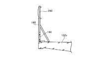
本実施形態の張出架設工法では、張出架設の作業が終了するまでの間、壁高欄位置に仮固定されたプレキャストコンクリートパネル140を、工事用防護柵200の背面を支持するための支持材として利用する。
In the overhanging construction method according to the present embodiment, the support material for supporting the back surface of the
図2に戻って、新設橋体ブロック102fが構築された後の張出架設作業について説明する。
Returning to FIG. 2, the overhanging work after the new
新設橋体ブロック102fが構築され、また、プレキャストコンクリートパネル140が壁高欄位置に仮固定された後、次の新設橋体ブロックの構築に備え、レール120の仮固定を解除し、構築した橋体ブロック102f上にレール120を前進させ再度仮固定して、張出架設用移動作業車110を、構築した橋体ブロック102f上まで前進させる。
After the new
以下、図2〜図9を参照して説明した作業を繰り返し、プレキャストコンクリートパネル140を仮固定しながら、次々と橋体ブロックを継ぎ足す。そして、橋脚の中間で橋体を連結し、連続ケーブル(図示省略)を緊張して橋梁上部工に橋軸方向のプレストレスを導入して、張出架設作業、およびプレキャストコンクリートパネル140の仮固定作業を終了する。
Hereinafter, the work described with reference to FIGS. 2 to 9 is repeated, and the bridge block is added one after another while temporarily fixing the precast
図5〜図7を参照して、プレキャストコンクリートパネル140の立設姿勢調整および固定について説明する。
With reference to FIGS. 5 to 7, the standing posture adjustment and fixing of the precast
連続ケーブル(図示省略)を緊張して橋梁上部工に橋軸方向のプレストレスを導入した後、仮固定されたプレキャストコンクリートパネル140の位置および高さを測量し、所定の管理範囲内となるようにプレキャストコンクリートパネル140の立設姿勢を調整し、プレキャストコンクリートパネル140を壁高欄位置に固定する。より詳細には、仮固定されたプレキャストコンクリートパネル140の固定を一旦緩め、連結金具143によるパネル側固定金具142と既設橋体ブロック側金具144との連結の位置を、第1の長孔142aおよび第2の長孔144aそれぞれの孔内で選択することにより、橋梁上部工に対するプレキャストコンクリートパネル140の上下方向高さ位置および傾きを調整する。その後、パネル側固定金具142と既設橋体ブロック側金具144とを、連結金具143を用いて再度固定する。
After tensioning the continuous cable (not shown) and introducing prestress in the direction of the bridge axis to the bridge superstructure, the position and height of the temporarily fixed precast
図10は、コンクリート壁高欄の施工を説明する、橋軸に直角な断面図である。また、図11は、施工されたコンクリート壁高欄の、橋軸に直角な断面図である。 FIG. 10 is a cross-sectional view perpendicular to the bridge axis for explaining the construction of the concrete wall rail. FIG. 11 is a cross-sectional view of the constructed concrete wall rail perpendicular to the bridge axis.
プレキャストコンクリートパネル140の立設姿勢が調整され固定された後、壁高欄の鉄筋を配筋し、壁高欄内面形成用型枠150を立設し、プレキャストコンクリートパネル140と壁高欄内面形成用型枠150との間の空間に壁高欄のコンクリートを打設する。これによりコンクリート壁高欄160が施工される。
After the standing posture of the precast
以上説明した本実施形態によれば、張出架設の作業と同時並行的に、壁高欄外面となるプレキャストコンクリートパネ140ルを仮固定するため、この仮固定の作業には、張出架設の作業に用いる作業用吊り足場115,116を利用することができる。また、本実施形態によれば、張出架設の作業終了後、プレキャストコンクリートパネル140の立設姿勢を調整した後に固定するため、張出架設の施工段階において張出床版上面の高さが変化したとしても、その調整によって、壁高欄の高さや平面線形の仕上がりが高い精度で整えられる。また、本実施形態によれば、張出架設の作業終了後、橋梁上部工における壁高欄位置よりも外側に改めて足場を設けたり、地盤から支保工を組み上げたり、作業台車を別途設置したりすることが不要であるため、従来よりも工期を短縮することができ、コストが削減される。
According to the embodiment described above, the precast
尚、本実施形態では、PC橋の橋梁上部工を場所打ちコンクリートにより張出架設する例を挙げたが、PC橋の橋梁上部工をプレキャスト部材を用いて張出架設してもよい。 In this embodiment, an example is described in which the bridge superstructure of the PC bridge is overhanged by cast-in-place concrete. However, the bridge superstructure of the PC bridge may be stretched using a precast member.
P1,P2,P3,P4 橋脚
101,102,103,104 橋体ブロック
105 橋台
110 張出架設用移動作業車
111 メインフレーム
112 横梁
113 鋼棒
114 型枠支持材
115,116 作業用吊り足場
117 反力支持装置
120 レール
130 水切り
131 凹部
140 プレキャストコンクリートパネル
141 位置決め金具
142 パネル側固定金具
142a 第1の長孔
143 連結金具
144 既設橋体ブロック側金具
144a 第2の長孔
1441 斜材
1442 平行材
1443 固定材
150 壁高欄内面形成用型枠
160 コンクリート壁高欄
10 アンカ
11 位置決めボルト
20 ジャッキ
30 型枠
31 凸部
200 工事用防護柵
P1, P2, P3,
Claims (3)
Priority Applications (1)
| Application Number | Priority Date | Filing Date | Title |
|---|---|---|---|
| JP2011197384A JP5773814B2 (en) | 2011-09-09 | 2011-09-09 | Construction method of wall rail of overhanging PC bridge |
Applications Claiming Priority (1)
| Application Number | Priority Date | Filing Date | Title |
|---|---|---|---|
| JP2011197384A JP5773814B2 (en) | 2011-09-09 | 2011-09-09 | Construction method of wall rail of overhanging PC bridge |
Publications (2)
| Publication Number | Publication Date |
|---|---|
| JP2013057215A JP2013057215A (en) | 2013-03-28 |
| JP5773814B2 true JP5773814B2 (en) | 2015-09-02 |
Family
ID=48133300
Family Applications (1)
| Application Number | Title | Priority Date | Filing Date |
|---|---|---|---|
| JP2011197384A Active JP5773814B2 (en) | 2011-09-09 | 2011-09-09 | Construction method of wall rail of overhanging PC bridge |
Country Status (1)
| Country | Link |
|---|---|
| JP (1) | JP5773814B2 (en) |
Families Citing this family (10)
| Publication number | Priority date | Publication date | Assignee | Title |
|---|---|---|---|---|
| CN103255717A (en) * | 2013-04-28 | 2013-08-21 | 中国五冶集团有限公司 | Method for constructing hit-preventing wall |
| CN103911951B (en) * | 2014-02-27 | 2015-08-26 | 北京城建道桥建设集团有限公司 | The cast-in-place anticollision barrier of bridge integral type and link plate dedicated templates and construction method thereof |
| JP6537369B2 (en) * | 2015-06-25 | 2019-07-03 | 三井住友建設株式会社 | Precast bridge members |
| CN105484163B (en) * | 2015-12-23 | 2017-06-09 | 中铁大桥局集团第五工程有限公司 | Pier construction method after a kind of cable-stayed bridge auxiliary pier pier top sections elder generation beam |
| CN106049285B (en) * | 2016-06-07 | 2018-06-19 | 中铁港航局集团有限公司 | A kind of method of the cast-in-place colored pool anti-collision wall formwork reinforcement of urban interchange |
| JP6889010B2 (en) * | 2017-04-17 | 2021-06-18 | 清水建設株式会社 | Bridge construction method |
| CN110184920B (en) * | 2019-04-28 | 2020-10-30 | 安徽省公路桥梁工程有限公司 | Construction method of flower basket integrated anti-collision guardrail |
| JP7134133B2 (en) * | 2019-05-09 | 2022-09-09 | 鹿島建設株式会社 | Bridge railing construction method |
| CN110344326A (en) * | 2019-07-12 | 2019-10-18 | 广州北环高速公路有限公司 | Protective fence formwork for placing |
| CN114561874B (en) * | 2022-03-18 | 2024-01-16 | 四川华远建设工程有限公司 | Outsourcing formula anticollision barrier template reinforced structure |
Family Cites Families (4)
| Publication number | Priority date | Publication date | Assignee | Title |
|---|---|---|---|---|
| JP3064834B2 (en) * | 1994-11-18 | 2000-07-12 | 日本軽金属株式会社 | Bridge girder cover mounting structure |
| JP3636960B2 (en) * | 2000-03-31 | 2005-04-06 | 瀧上工業株式会社 | Half precast wall member and civil engineering construction method using the half precast wall member |
| JP3862707B2 (en) * | 2004-03-19 | 2006-12-27 | 日本カイザー株式会社 | Construction method of overpass slab and precast concrete plate for overhang slab |
| JP2006009339A (en) * | 2004-06-24 | 2006-01-12 | Kawada Industries Inc | Construction method for building continuous composite girder bridge |
-
2011
- 2011-09-09 JP JP2011197384A patent/JP5773814B2/en active Active
Also Published As
| Publication number | Publication date |
|---|---|
| JP2013057215A (en) | 2013-03-28 |
Similar Documents
| Publication | Publication Date | Title |
|---|---|---|
| JP5773814B2 (en) | Construction method of wall rail of overhanging PC bridge | |
| KR101765762B1 (en) | Cantilever part for bridge and constructing method thereof | |
| KR100999660B1 (en) | multi span precast parts which has a construction improvement function | |
| JP5405337B2 (en) | Construction method of railway RC ramen structure viaduct | |
| JP5045214B2 (en) | Column head construction method | |
| JP2007077630A (en) | Continuous girder using precast main-girder segment, and its erection method | |
| KR101101204B1 (en) | Cantilever of slab for steel box bridge using steel supporter and the method thereof | |
| KR20160001216A (en) | Rahmen using hinge type pc wall and method for constructing the same | |
| JPH08269911A (en) | Structure of attaching part of concrete wall transom | |
| CN108316150B (en) | Construction system and construction method for main tower and steel anchor beam of cable-stayed bridge | |
| KR101735077B1 (en) | Bridge deck using precast concrete panel | |
| KR102269141B1 (en) | Deck plate wall installation method using underground pavement | |
| JP6509096B2 (en) | Extension method | |
| KR20090070852A (en) | Method and apparatus for constructing boader stones between footway and roadway | |
| KR20130042526A (en) | Attachment plates adjoining ends of concrete beam with walls of abutments, and method of building concrete structure using the same | |
| KR20070001410A (en) | Mounting structure of steel cross-beam in multi-girder concrete bridge and its construction method | |
| JP2010121434A (en) | Method for installing road-bridge-width expansion material | |
| JP3896032B2 (en) | Construction method of precast column head and pier column head | |
| JP6652755B2 (en) | Joint structure and joining method between road deck and PCa wall railing | |
| JP7134133B2 (en) | Bridge railing construction method | |
| KR100778139B1 (en) | Frame for length adjustment in horizontal prop of mold | |
| CN112482316A (en) | Gate dam gate machine beam construction method and gate dam gate machine beam structure | |
| JP6002013B2 (en) | Temporary material support device | |
| JP6495846B2 (en) | Slope anchor construction method and rail unit set used therefor | |
| JP2003056186A5 (en) |
Legal Events
| Date | Code | Title | Description |
|---|---|---|---|
| A621 | Written request for application examination |
Free format text: JAPANESE INTERMEDIATE CODE: A621 Effective date: 20140630 |
|
| A131 | Notification of reasons for refusal |
Free format text: JAPANESE INTERMEDIATE CODE: A131 Effective date: 20150317 |
|
| A977 | Report on retrieval |
Free format text: JAPANESE INTERMEDIATE CODE: A971007 Effective date: 20150318 |
|
| A521 | Request for written amendment filed |
Free format text: JAPANESE INTERMEDIATE CODE: A523 Effective date: 20150428 |
|
| TRDD | Decision of grant or rejection written | ||
| A01 | Written decision to grant a patent or to grant a registration (utility model) |
Free format text: JAPANESE INTERMEDIATE CODE: A01 Effective date: 20150630 |
|
| A61 | First payment of annual fees (during grant procedure) |
Free format text: JAPANESE INTERMEDIATE CODE: A61 Effective date: 20150630 |
|
| R150 | Certificate of patent or registration of utility model |
Ref document number: 5773814 Country of ref document: JP Free format text: JAPANESE INTERMEDIATE CODE: R150 |
|
| R250 | Receipt of annual fees |
Free format text: JAPANESE INTERMEDIATE CODE: R250 |
|
| R250 | Receipt of annual fees |
Free format text: JAPANESE INTERMEDIATE CODE: R250 |
|
| S531 | Written request for registration of change of domicile |
Free format text: JAPANESE INTERMEDIATE CODE: R313531 |
|
| S531 | Written request for registration of change of domicile |
Free format text: JAPANESE INTERMEDIATE CODE: R313531 |
|
| R350 | Written notification of registration of transfer |
Free format text: JAPANESE INTERMEDIATE CODE: R350 |