JP5773634B2 - Double-sided recording medium - Google Patents
Double-sided recording medium Download PDFInfo
- Publication number
- JP5773634B2 JP5773634B2 JP2010277324A JP2010277324A JP5773634B2 JP 5773634 B2 JP5773634 B2 JP 5773634B2 JP 2010277324 A JP2010277324 A JP 2010277324A JP 2010277324 A JP2010277324 A JP 2010277324A JP 5773634 B2 JP5773634 B2 JP 5773634B2
- Authority
- JP
- Japan
- Prior art keywords
- ink receiving
- receiving layer
- recording medium
- surface side
- outermost
- Prior art date
- Legal status (The legal status is an assumption and is not a legal conclusion. Google has not performed a legal analysis and makes no representation as to the accuracy of the status listed.)
- Active
Links
- 239000011148 porous material Substances 0.000 claims abstract description 65
- 239000011230 binding agent Substances 0.000 claims abstract description 20
- 238000009826 distribution Methods 0.000 claims abstract description 17
- 238000000576 coating method Methods 0.000 claims description 81
- 239000011248 coating agent Substances 0.000 claims description 80
- PNEYBMLMFCGWSK-UHFFFAOYSA-N aluminium oxide Inorganic materials [O-2].[O-2].[O-2].[Al+3].[Al+3] PNEYBMLMFCGWSK-UHFFFAOYSA-N 0.000 claims description 35
- 239000000049 pigment Substances 0.000 abstract description 17
- 239000000758 substrate Substances 0.000 abstract 2
- 239000010410 layer Substances 0.000 description 199
- 239000007788 liquid Substances 0.000 description 55
- 238000000034 method Methods 0.000 description 34
- KGBXLFKZBHKPEV-UHFFFAOYSA-N boric acid Chemical compound OB(O)O KGBXLFKZBHKPEV-UHFFFAOYSA-N 0.000 description 19
- 235000010338 boric acid Nutrition 0.000 description 19
- 239000007787 solid Substances 0.000 description 19
- IJGRMHOSHXDMSA-UHFFFAOYSA-N Atomic nitrogen Chemical compound N#N IJGRMHOSHXDMSA-UHFFFAOYSA-N 0.000 description 18
- 229960002645 boric acid Drugs 0.000 description 18
- 239000000123 paper Substances 0.000 description 18
- 229920002451 polyvinyl alcohol Polymers 0.000 description 18
- 235000019422 polyvinyl alcohol Nutrition 0.000 description 18
- 239000004327 boric acid Substances 0.000 description 17
- 238000002360 preparation method Methods 0.000 description 15
- 239000004372 Polyvinyl alcohol Substances 0.000 description 14
- VYPSYNLAJGMNEJ-UHFFFAOYSA-N Silicium dioxide Chemical compound O=[Si]=O VYPSYNLAJGMNEJ-UHFFFAOYSA-N 0.000 description 13
- 238000005259 measurement Methods 0.000 description 11
- 239000002245 particle Substances 0.000 description 11
- 229920000642 polymer Polymers 0.000 description 11
- 239000000243 solution Substances 0.000 description 11
- -1 polyethylene Polymers 0.000 description 10
- 229920005989 resin Polymers 0.000 description 10
- 239000011347 resin Substances 0.000 description 10
- 229910052757 nitrogen Inorganic materials 0.000 description 8
- 238000002336 sorption--desorption measurement Methods 0.000 description 8
- 238000001179 sorption measurement Methods 0.000 description 7
- XLYOFNOQVPJJNP-UHFFFAOYSA-N water Substances O XLYOFNOQVPJJNP-UHFFFAOYSA-N 0.000 description 7
- QTBSBXVTEAMEQO-UHFFFAOYSA-N Acetic acid Chemical compound CC(O)=O QTBSBXVTEAMEQO-UHFFFAOYSA-N 0.000 description 6
- VTYYLEPIZMXCLO-UHFFFAOYSA-L Calcium carbonate Chemical compound [Ca+2].[O-]C([O-])=O VTYYLEPIZMXCLO-UHFFFAOYSA-L 0.000 description 6
- 125000002091 cationic group Chemical group 0.000 description 6
- 238000001035 drying Methods 0.000 description 6
- 239000000975 dye Substances 0.000 description 6
- 238000004438 BET method Methods 0.000 description 5
- 230000000052 comparative effect Effects 0.000 description 5
- 239000000463 material Substances 0.000 description 5
- 239000000377 silicon dioxide Substances 0.000 description 5
- AEMRFAOFKBGASW-UHFFFAOYSA-N Glycolic acid Chemical compound OCC(O)=O AEMRFAOFKBGASW-UHFFFAOYSA-N 0.000 description 4
- VEXZGXHMUGYJMC-UHFFFAOYSA-N Hydrochloric acid Chemical compound Cl VEXZGXHMUGYJMC-UHFFFAOYSA-N 0.000 description 4
- AFVFQIVMOAPDHO-UHFFFAOYSA-N Methanesulfonic acid Chemical compound CS(O)(=O)=O AFVFQIVMOAPDHO-UHFFFAOYSA-N 0.000 description 4
- 238000010521 absorption reaction Methods 0.000 description 4
- 239000007864 aqueous solution Substances 0.000 description 4
- 239000003795 chemical substances by application Substances 0.000 description 4
- FAHBNUUHRFUEAI-UHFFFAOYSA-M hydroxidooxidoaluminium Chemical group O[Al]=O FAHBNUUHRFUEAI-UHFFFAOYSA-M 0.000 description 4
- 239000004816 latex Substances 0.000 description 4
- 229920000126 latex Polymers 0.000 description 4
- BDAGIHXWWSANSR-UHFFFAOYSA-N methanoic acid Natural products OC=O BDAGIHXWWSANSR-UHFFFAOYSA-N 0.000 description 4
- 238000006116 polymerization reaction Methods 0.000 description 4
- 150000003839 salts Chemical class 0.000 description 4
- WFDIJRYMOXRFFG-UHFFFAOYSA-N Acetic anhydride Chemical compound CC(=O)OC(C)=O WFDIJRYMOXRFFG-UHFFFAOYSA-N 0.000 description 3
- BTBUEUYNUDRHOZ-UHFFFAOYSA-N Borate Chemical compound [O-]B([O-])[O-] BTBUEUYNUDRHOZ-UHFFFAOYSA-N 0.000 description 3
- OFOBLEOULBTSOW-UHFFFAOYSA-N Malonic acid Chemical compound OC(=O)CC(O)=O OFOBLEOULBTSOW-UHFFFAOYSA-N 0.000 description 3
- MUBZPKHOEPUJKR-UHFFFAOYSA-N Oxalic acid Chemical compound OC(=O)C(O)=O MUBZPKHOEPUJKR-UHFFFAOYSA-N 0.000 description 3
- 239000004698 Polyethylene Substances 0.000 description 3
- 229920002472 Starch Polymers 0.000 description 3
- 239000002253 acid Substances 0.000 description 3
- 229910000019 calcium carbonate Inorganic materials 0.000 description 3
- 229920006317 cationic polymer Polymers 0.000 description 3
- KRKNYBCHXYNGOX-UHFFFAOYSA-N citric acid Chemical compound OC(=O)CC(O)(C(O)=O)CC(O)=O KRKNYBCHXYNGOX-UHFFFAOYSA-N 0.000 description 3
- 238000001816 cooling Methods 0.000 description 3
- 230000000694 effects Effects 0.000 description 3
- 238000001125 extrusion Methods 0.000 description 3
- 238000011049 filling Methods 0.000 description 3
- 239000001023 inorganic pigment Substances 0.000 description 3
- 238000004519 manufacturing process Methods 0.000 description 3
- 239000012860 organic pigment Substances 0.000 description 3
- 229920000573 polyethylene Polymers 0.000 description 3
- 229920005672 polyolefin resin Polymers 0.000 description 3
- 238000007127 saponification reaction Methods 0.000 description 3
- 239000008107 starch Substances 0.000 description 3
- 235000019698 starch Nutrition 0.000 description 3
- 239000000126 substance Substances 0.000 description 3
- OSWFIVFLDKOXQC-UHFFFAOYSA-N 4-(3-methoxyphenyl)aniline Chemical compound COC1=CC=CC(C=2C=CC(N)=CC=2)=C1 OSWFIVFLDKOXQC-UHFFFAOYSA-N 0.000 description 2
- RGHNJXZEOKUKBD-SQOUGZDYSA-N D-gluconic acid Chemical compound OC[C@@H](O)[C@@H](O)[C@H](O)[C@@H](O)C(O)=O RGHNJXZEOKUKBD-SQOUGZDYSA-N 0.000 description 2
- 239000004640 Melamine resin Substances 0.000 description 2
- 229920000877 Melamine resin Polymers 0.000 description 2
- GRYLNZFGIOXLOG-UHFFFAOYSA-N Nitric acid Chemical compound O[N+]([O-])=O GRYLNZFGIOXLOG-UHFFFAOYSA-N 0.000 description 2
- NBIIXXVUZAFLBC-UHFFFAOYSA-N Phosphoric acid Chemical compound OP(O)(O)=O NBIIXXVUZAFLBC-UHFFFAOYSA-N 0.000 description 2
- PPBRXRYQALVLMV-UHFFFAOYSA-N Styrene Chemical compound C=CC1=CC=CC=C1 PPBRXRYQALVLMV-UHFFFAOYSA-N 0.000 description 2
- KKEYFWRCBNTPAC-UHFFFAOYSA-N Terephthalic acid Chemical compound OC(=O)C1=CC=C(C(O)=O)C=C1 KKEYFWRCBNTPAC-UHFFFAOYSA-N 0.000 description 2
- 229920001807 Urea-formaldehyde Polymers 0.000 description 2
- 150000007513 acids Chemical class 0.000 description 2
- WNLRTRBMVRJNCN-UHFFFAOYSA-N adipic acid Chemical compound OC(=O)CCCCC(O)=O WNLRTRBMVRJNCN-UHFFFAOYSA-N 0.000 description 2
- 125000000129 anionic group Chemical group 0.000 description 2
- 239000002518 antifoaming agent Substances 0.000 description 2
- WPYMKLBDIGXBTP-UHFFFAOYSA-N benzoic acid Chemical compound OC(=O)C1=CC=CC=C1 WPYMKLBDIGXBTP-UHFFFAOYSA-N 0.000 description 2
- 230000008859 change Effects 0.000 description 2
- 239000013078 crystal Substances 0.000 description 2
- XBDQKXXYIPTUBI-UHFFFAOYSA-N dimethylselenoniopropionate Natural products CCC(O)=O XBDQKXXYIPTUBI-UHFFFAOYSA-N 0.000 description 2
- 229910001873 dinitrogen Inorganic materials 0.000 description 2
- 239000006185 dispersion Substances 0.000 description 2
- 238000011156 evaluation Methods 0.000 description 2
- 235000019253 formic acid Nutrition 0.000 description 2
- 239000007789 gas Substances 0.000 description 2
- 230000014509 gene expression Effects 0.000 description 2
- 238000010438 heat treatment Methods 0.000 description 2
- 230000001788 irregular Effects 0.000 description 2
- QQVIHTHCMHWDBS-UHFFFAOYSA-N isophthalic acid Chemical compound OC(=O)C1=CC=CC(C(O)=O)=C1 QQVIHTHCMHWDBS-UHFFFAOYSA-N 0.000 description 2
- JVTAAEKCZFNVCJ-UHFFFAOYSA-N lactic acid Chemical compound CC(O)C(O)=O JVTAAEKCZFNVCJ-UHFFFAOYSA-N 0.000 description 2
- 229910052751 metal Inorganic materials 0.000 description 2
- 239000002184 metal Substances 0.000 description 2
- 229940098779 methanesulfonic acid Drugs 0.000 description 2
- 238000000465 moulding Methods 0.000 description 2
- 229910017604 nitric acid Inorganic materials 0.000 description 2
- 239000001254 oxidized starch Substances 0.000 description 2
- 235000013808 oxidized starch Nutrition 0.000 description 2
- XNGIFLGASWRNHJ-UHFFFAOYSA-N phthalic acid Chemical compound OC(=O)C1=CC=CC=C1C(O)=O XNGIFLGASWRNHJ-UHFFFAOYSA-N 0.000 description 2
- WLJVNTCWHIRURA-UHFFFAOYSA-N pimelic acid Chemical compound OC(=O)CCCCCC(O)=O WLJVNTCWHIRURA-UHFFFAOYSA-N 0.000 description 2
- 229920003229 poly(methyl methacrylate) Polymers 0.000 description 2
- 239000004926 polymethyl methacrylate Substances 0.000 description 2
- 229920000098 polyolefin Polymers 0.000 description 2
- 238000003756 stirring Methods 0.000 description 2
- TYFQFVWCELRYAO-UHFFFAOYSA-N suberic acid Chemical compound OC(=O)CCCCCCC(O)=O TYFQFVWCELRYAO-UHFFFAOYSA-N 0.000 description 2
- 230000003746 surface roughness Effects 0.000 description 2
- 229920003002 synthetic resin Polymers 0.000 description 2
- 239000000057 synthetic resin Substances 0.000 description 2
- 230000002123 temporal effect Effects 0.000 description 2
- 238000011282 treatment Methods 0.000 description 2
- ZSDSQXJSNMTJDA-UHFFFAOYSA-N trifluralin Chemical compound CCCN(CCC)C1=C([N+]([O-])=O)C=C(C(F)(F)F)C=C1[N+]([O-])=O ZSDSQXJSNMTJDA-UHFFFAOYSA-N 0.000 description 2
- JHPBZFOKBAGZBL-UHFFFAOYSA-N (3-hydroxy-2,2,4-trimethylpentyl) 2-methylprop-2-enoate Chemical compound CC(C)C(O)C(C)(C)COC(=O)C(C)=C JHPBZFOKBAGZBL-UHFFFAOYSA-N 0.000 description 1
- BJEPYKJPYRNKOW-REOHCLBHSA-N (S)-malic acid Chemical compound OC(=O)[C@@H](O)CC(O)=O BJEPYKJPYRNKOW-REOHCLBHSA-N 0.000 description 1
- RTBFRGCFXZNCOE-UHFFFAOYSA-N 1-methylsulfonylpiperidin-4-one Chemical compound CS(=O)(=O)N1CCC(=O)CC1 RTBFRGCFXZNCOE-UHFFFAOYSA-N 0.000 description 1
- XBNVWXKPFORCRI-UHFFFAOYSA-N 2h-naphtho[2,3-f]quinolin-1-one Chemical compound C1=CC=CC2=CC3=C4C(=O)CC=NC4=CC=C3C=C21 XBNVWXKPFORCRI-UHFFFAOYSA-N 0.000 description 1
- 229920002972 Acrylic fiber Polymers 0.000 description 1
- 229910002012 Aerosil® Inorganic materials 0.000 description 1
- 239000005995 Aluminium silicate Substances 0.000 description 1
- 239000005711 Benzoic acid Substances 0.000 description 1
- 229920002134 Carboxymethyl cellulose Polymers 0.000 description 1
- 108010076119 Caseins Proteins 0.000 description 1
- RGHNJXZEOKUKBD-UHFFFAOYSA-N D-gluconic acid Natural products OCC(O)C(O)C(O)C(O)C(O)=O RGHNJXZEOKUKBD-UHFFFAOYSA-N 0.000 description 1
- FEWJPZIEWOKRBE-JCYAYHJZSA-N Dextrotartaric acid Chemical compound OC(=O)[C@H](O)[C@@H](O)C(O)=O FEWJPZIEWOKRBE-JCYAYHJZSA-N 0.000 description 1
- 108010010803 Gelatin Proteins 0.000 description 1
- WHUUTDBJXJRKMK-UHFFFAOYSA-N Glutamic acid Natural products OC(=O)C(N)CCC(O)=O WHUUTDBJXJRKMK-UHFFFAOYSA-N 0.000 description 1
- 239000004354 Hydroxyethyl cellulose Substances 0.000 description 1
- 239000005909 Kieselgur Substances 0.000 description 1
- CKLJMWTZIZZHCS-REOHCLBHSA-N L-aspartic acid Chemical compound OC(=O)[C@@H](N)CC(O)=O CKLJMWTZIZZHCS-REOHCLBHSA-N 0.000 description 1
- WHUUTDBJXJRKMK-VKHMYHEASA-N L-glutamic acid Chemical compound OC(=O)[C@@H](N)CCC(O)=O WHUUTDBJXJRKMK-VKHMYHEASA-N 0.000 description 1
- FYYHWMGAXLPEAU-UHFFFAOYSA-N Magnesium Chemical compound [Mg] FYYHWMGAXLPEAU-UHFFFAOYSA-N 0.000 description 1
- 229920000881 Modified starch Polymers 0.000 description 1
- 229910019142 PO4 Inorganic materials 0.000 description 1
- 239000004743 Polypropylene Substances 0.000 description 1
- 239000004793 Polystyrene Substances 0.000 description 1
- NRCMAYZCPIVABH-UHFFFAOYSA-N Quinacridone Chemical compound N1C2=CC=CC=C2C(=O)C2=C1C=C1C(=O)C3=CC=CC=C3NC1=C2 NRCMAYZCPIVABH-UHFFFAOYSA-N 0.000 description 1
- 108010073771 Soybean Proteins Proteins 0.000 description 1
- KDYFGRWQOYBRFD-UHFFFAOYSA-N Succinic acid Natural products OC(=O)CCC(O)=O KDYFGRWQOYBRFD-UHFFFAOYSA-N 0.000 description 1
- FEWJPZIEWOKRBE-UHFFFAOYSA-N Tartaric acid Natural products [H+].[H+].[O-]C(=O)C(O)C(O)C([O-])=O FEWJPZIEWOKRBE-UHFFFAOYSA-N 0.000 description 1
- 229920002433 Vinyl chloride-vinyl acetate copolymer Polymers 0.000 description 1
- 238000002441 X-ray diffraction Methods 0.000 description 1
- YKTSYUJCYHOUJP-UHFFFAOYSA-N [O--].[Al+3].[Al+3].[O-][Si]([O-])([O-])[O-] Chemical compound [O--].[Al+3].[Al+3].[O-][Si]([O-])([O-])[O-] YKTSYUJCYHOUJP-UHFFFAOYSA-N 0.000 description 1
- 125000005396 acrylic acid ester group Chemical group 0.000 description 1
- 239000000654 additive Substances 0.000 description 1
- 239000000853 adhesive Substances 0.000 description 1
- 230000001070 adhesive effect Effects 0.000 description 1
- 239000001361 adipic acid Substances 0.000 description 1
- 235000011037 adipic acid Nutrition 0.000 description 1
- 229910052784 alkaline earth metal Inorganic materials 0.000 description 1
- 229920000180 alkyd Polymers 0.000 description 1
- BJEPYKJPYRNKOW-UHFFFAOYSA-N alpha-hydroxysuccinic acid Natural products OC(=O)C(O)CC(O)=O BJEPYKJPYRNKOW-UHFFFAOYSA-N 0.000 description 1
- WNROFYMDJYEPJX-UHFFFAOYSA-K aluminium hydroxide Chemical class [OH-].[OH-].[OH-].[Al+3] WNROFYMDJYEPJX-UHFFFAOYSA-K 0.000 description 1
- 229910000147 aluminium phosphate Inorganic materials 0.000 description 1
- 235000012211 aluminium silicate Nutrition 0.000 description 1
- 150000003863 ammonium salts Chemical class 0.000 description 1
- 238000004458 analytical method Methods 0.000 description 1
- JFCQEDHGNNZCLN-UHFFFAOYSA-N anhydrous glutaric acid Natural products OC(=O)CCCC(O)=O JFCQEDHGNNZCLN-UHFFFAOYSA-N 0.000 description 1
- 230000002421 anti-septic effect Effects 0.000 description 1
- 239000003429 antifungal agent Substances 0.000 description 1
- 229940121375 antifungal agent Drugs 0.000 description 1
- 239000003963 antioxidant agent Substances 0.000 description 1
- 230000003078 antioxidant effect Effects 0.000 description 1
- 239000008346 aqueous phase Substances 0.000 description 1
- 235000003704 aspartic acid Nutrition 0.000 description 1
- QVQLCTNNEUAWMS-UHFFFAOYSA-N barium oxide Chemical compound [Ba]=O QVQLCTNNEUAWMS-UHFFFAOYSA-N 0.000 description 1
- 229910001864 baryta Inorganic materials 0.000 description 1
- 230000008901 benefit Effects 0.000 description 1
- 235000010233 benzoic acid Nutrition 0.000 description 1
- OQFSQFPPLPISGP-UHFFFAOYSA-N beta-carboxyaspartic acid Natural products OC(=O)C(N)C(C(O)=O)C(O)=O OQFSQFPPLPISGP-UHFFFAOYSA-N 0.000 description 1
- 230000015572 biosynthetic process Effects 0.000 description 1
- 125000005619 boric acid group Chemical class 0.000 description 1
- KDYFGRWQOYBRFD-NUQCWPJISA-N butanedioic acid Chemical compound O[14C](=O)CC[14C](O)=O KDYFGRWQOYBRFD-NUQCWPJISA-N 0.000 description 1
- 159000000007 calcium salts Chemical class 0.000 description 1
- 239000000378 calcium silicate Substances 0.000 description 1
- 229910052918 calcium silicate Inorganic materials 0.000 description 1
- OYACROKNLOSFPA-UHFFFAOYSA-N calcium;dioxido(oxo)silane Chemical compound [Ca+2].[O-][Si]([O-])=O OYACROKNLOSFPA-UHFFFAOYSA-N 0.000 description 1
- 125000003178 carboxy group Chemical group [H]OC(*)=O 0.000 description 1
- 239000001768 carboxy methyl cellulose Substances 0.000 description 1
- 235000010948 carboxy methyl cellulose Nutrition 0.000 description 1
- 229920003090 carboxymethyl hydroxyethyl cellulose Polymers 0.000 description 1
- 239000008112 carboxymethyl-cellulose Substances 0.000 description 1
- 239000005018 casein Substances 0.000 description 1
- BECPQYXYKAMYBN-UHFFFAOYSA-N casein, tech. Chemical compound NCCCCC(C(O)=O)N=C(O)C(CC(O)=O)N=C(O)C(CCC(O)=N)N=C(O)C(CC(C)C)N=C(O)C(CCC(O)=O)N=C(O)C(CC(O)=O)N=C(O)C(CCC(O)=O)N=C(O)C(C(C)O)N=C(O)C(CCC(O)=N)N=C(O)C(CCC(O)=N)N=C(O)C(CCC(O)=N)N=C(O)C(CCC(O)=O)N=C(O)C(CCC(O)=O)N=C(O)C(COP(O)(O)=O)N=C(O)C(CCC(O)=N)N=C(O)C(N)CC1=CC=CC=C1 BECPQYXYKAMYBN-UHFFFAOYSA-N 0.000 description 1
- 235000021240 caseins Nutrition 0.000 description 1
- 150000001767 cationic compounds Chemical class 0.000 description 1
- 239000003093 cationic surfactant Substances 0.000 description 1
- 239000001913 cellulose Substances 0.000 description 1
- 229920002678 cellulose Polymers 0.000 description 1
- 229920002301 cellulose acetate Polymers 0.000 description 1
- 230000001886 ciliary effect Effects 0.000 description 1
- 235000015165 citric acid Nutrition 0.000 description 1
- 229920006026 co-polymeric resin Polymers 0.000 description 1
- 239000011247 coating layer Substances 0.000 description 1
- 239000008119 colloidal silica Substances 0.000 description 1
- 239000006103 coloring component Substances 0.000 description 1
- 229920000547 conjugated polymer Polymers 0.000 description 1
- 229920001577 copolymer Polymers 0.000 description 1
- 238000003851 corona treatment Methods 0.000 description 1
- 238000003795 desorption Methods 0.000 description 1
- 238000011161 development Methods 0.000 description 1
- 239000002270 dispersing agent Substances 0.000 description 1
- 238000004043 dyeing Methods 0.000 description 1
- 239000005038 ethylene vinyl acetate Substances 0.000 description 1
- 238000007765 extrusion coating Methods 0.000 description 1
- 239000010419 fine particle Substances 0.000 description 1
- 239000006081 fluorescent whitening agent Substances 0.000 description 1
- 238000005187 foaming Methods 0.000 description 1
- 125000000524 functional group Chemical group 0.000 description 1
- 229920000159 gelatin Polymers 0.000 description 1
- 239000008273 gelatin Substances 0.000 description 1
- 235000019322 gelatine Nutrition 0.000 description 1
- 235000011852 gelatine desserts Nutrition 0.000 description 1
- 239000011521 glass Substances 0.000 description 1
- 239000000174 gluconic acid Substances 0.000 description 1
- 235000012208 gluconic acid Nutrition 0.000 description 1
- 235000013922 glutamic acid Nutrition 0.000 description 1
- 239000004220 glutamic acid Substances 0.000 description 1
- 239000011121 hardwood Substances 0.000 description 1
- 229920001903 high density polyethylene Polymers 0.000 description 1
- 239000004700 high-density polyethylene Substances 0.000 description 1
- 230000003301 hydrolyzing effect Effects 0.000 description 1
- 235000019447 hydroxyethyl cellulose Nutrition 0.000 description 1
- SKOWZLGOFVSKLB-UHFFFAOYSA-N hypodiboric acid Chemical compound OB(O)B(O)O SKOWZLGOFVSKLB-UHFFFAOYSA-N 0.000 description 1
- 230000001771 impaired effect Effects 0.000 description 1
- 239000010954 inorganic particle Substances 0.000 description 1
- NLYAJNPCOHFWQQ-UHFFFAOYSA-N kaolin Chemical compound O.O.O=[Al]O[Si](=O)O[Si](=O)O[Al]=O NLYAJNPCOHFWQQ-UHFFFAOYSA-N 0.000 description 1
- 239000002655 kraft paper Substances 0.000 description 1
- 239000004310 lactic acid Substances 0.000 description 1
- 235000014655 lactic acid Nutrition 0.000 description 1
- 229920001684 low density polyethylene Polymers 0.000 description 1
- 239000004702 low-density polyethylene Substances 0.000 description 1
- 229910052749 magnesium Inorganic materials 0.000 description 1
- 239000011777 magnesium Substances 0.000 description 1
- ZLNQQNXFFQJAID-UHFFFAOYSA-L magnesium carbonate Chemical compound [Mg+2].[O-]C([O-])=O ZLNQQNXFFQJAID-UHFFFAOYSA-L 0.000 description 1
- 239000001095 magnesium carbonate Substances 0.000 description 1
- 229910000021 magnesium carbonate Inorganic materials 0.000 description 1
- VTHJTEIRLNZDEV-UHFFFAOYSA-L magnesium dihydroxide Chemical compound [OH-].[OH-].[Mg+2] VTHJTEIRLNZDEV-UHFFFAOYSA-L 0.000 description 1
- 239000000347 magnesium hydroxide Substances 0.000 description 1
- 229910001862 magnesium hydroxide Inorganic materials 0.000 description 1
- 239000000391 magnesium silicate Substances 0.000 description 1
- 229910052919 magnesium silicate Inorganic materials 0.000 description 1
- 235000019792 magnesium silicate Nutrition 0.000 description 1
- ZADYMNAVLSWLEQ-UHFFFAOYSA-N magnesium;oxygen(2-);silicon(4+) Chemical compound [O-2].[O-2].[O-2].[Mg+2].[Si+4] ZADYMNAVLSWLEQ-UHFFFAOYSA-N 0.000 description 1
- VZCYOOQTPOCHFL-UPHRSURJSA-N maleic acid Chemical compound OC(=O)\C=C/C(O)=O VZCYOOQTPOCHFL-UPHRSURJSA-N 0.000 description 1
- 239000011976 maleic acid Substances 0.000 description 1
- FPYJFEHAWHCUMM-UHFFFAOYSA-N maleic anhydride Chemical compound O=C1OC(=O)C=C1 FPYJFEHAWHCUMM-UHFFFAOYSA-N 0.000 description 1
- 239000001630 malic acid Substances 0.000 description 1
- 235000011090 malic acid Nutrition 0.000 description 1
- 125000005397 methacrylic acid ester group Chemical group 0.000 description 1
- 239000003094 microcapsule Substances 0.000 description 1
- 230000005012 migration Effects 0.000 description 1
- 238000013508 migration Methods 0.000 description 1
- 150000007522 mineralic acids Chemical class 0.000 description 1
- 239000000203 mixture Substances 0.000 description 1
- 235000019426 modified starch Nutrition 0.000 description 1
- 239000006082 mold release agent Substances 0.000 description 1
- 239000000178 monomer Substances 0.000 description 1
- 230000007935 neutral effect Effects 0.000 description 1
- 150000007524 organic acids Chemical class 0.000 description 1
- 235000005985 organic acids Nutrition 0.000 description 1
- 239000011146 organic particle Substances 0.000 description 1
- 235000006408 oxalic acid Nutrition 0.000 description 1
- VGTPKLINSHNZRD-UHFFFAOYSA-N oxoborinic acid Chemical compound OB=O VGTPKLINSHNZRD-UHFFFAOYSA-N 0.000 description 1
- 239000003002 pH adjusting agent Substances 0.000 description 1
- 238000000059 patterning Methods 0.000 description 1
- NBIIXXVUZAFLBC-UHFFFAOYSA-K phosphate Chemical compound [O-]P([O-])([O-])=O NBIIXXVUZAFLBC-UHFFFAOYSA-K 0.000 description 1
- 239000010452 phosphate Substances 0.000 description 1
- 229920003023 plastic Polymers 0.000 description 1
- 239000004033 plastic Substances 0.000 description 1
- 229920001200 poly(ethylene-vinyl acetate) Polymers 0.000 description 1
- 229920000747 poly(lactic acid) Polymers 0.000 description 1
- 229920002037 poly(vinyl butyral) polymer Polymers 0.000 description 1
- 229920000058 polyacrylate Polymers 0.000 description 1
- 239000004417 polycarbonate Substances 0.000 description 1
- 229920000515 polycarbonate Polymers 0.000 description 1
- 229920000728 polyester Polymers 0.000 description 1
- 229920000139 polyethylene terephthalate Polymers 0.000 description 1
- 239000005020 polyethylene terephthalate Substances 0.000 description 1
- 239000004626 polylactic acid Substances 0.000 description 1
- 230000000379 polymerizing effect Effects 0.000 description 1
- 229920001155 polypropylene Polymers 0.000 description 1
- 229920002223 polystyrene Polymers 0.000 description 1
- 229920005749 polyurethane resin Polymers 0.000 description 1
- 239000011118 polyvinyl acetate Substances 0.000 description 1
- 229920002689 polyvinyl acetate Polymers 0.000 description 1
- 239000004800 polyvinyl chloride Substances 0.000 description 1
- 229920000915 polyvinyl chloride Polymers 0.000 description 1
- 229920000036 polyvinylpyrrolidone Polymers 0.000 description 1
- 239000001267 polyvinylpyrrolidone Substances 0.000 description 1
- 235000013855 polyvinylpyrrolidone Nutrition 0.000 description 1
- XAEFZNCEHLXOMS-UHFFFAOYSA-M potassium benzoate Chemical compound [K+].[O-]C(=O)C1=CC=CC=C1 XAEFZNCEHLXOMS-UHFFFAOYSA-M 0.000 description 1
- 239000000843 powder Substances 0.000 description 1
- 239000003755 preservative agent Substances 0.000 description 1
- 230000002335 preservative effect Effects 0.000 description 1
- 235000019260 propionic acid Nutrition 0.000 description 1
- IUVKMZGDUIUOCP-BTNSXGMBSA-N quinbolone Chemical compound O([C@H]1CC[C@H]2[C@H]3[C@@H]([C@]4(C=CC(=O)C=C4CC3)C)CC[C@@]21C)C1=CCCC1 IUVKMZGDUIUOCP-BTNSXGMBSA-N 0.000 description 1
- 230000009467 reduction Effects 0.000 description 1
- 239000011342 resin composition Substances 0.000 description 1
- 230000004044 response Effects 0.000 description 1
- 238000000926 separation method Methods 0.000 description 1
- 238000007493 shaping process Methods 0.000 description 1
- 238000004513 sizing Methods 0.000 description 1
- 239000002002 slurry Substances 0.000 description 1
- 239000011734 sodium Substances 0.000 description 1
- 159000000000 sodium salts Chemical class 0.000 description 1
- 229940001941 soy protein Drugs 0.000 description 1
- 238000003860 storage Methods 0.000 description 1
- 229920003048 styrene butadiene rubber Polymers 0.000 description 1
- 229940014800 succinic anhydride Drugs 0.000 description 1
- 239000004094 surface-active agent Substances 0.000 description 1
- 239000000725 suspension Substances 0.000 description 1
- 229910002029 synthetic silica gel Inorganic materials 0.000 description 1
- 239000011975 tartaric acid Substances 0.000 description 1
- 235000002906 tartaric acid Nutrition 0.000 description 1
- 229920001187 thermosetting polymer Polymers 0.000 description 1
- 239000002562 thickening agent Substances 0.000 description 1
- VZCYOOQTPOCHFL-UHFFFAOYSA-N trans-butenedioic acid Natural products OC(=O)C=CC(O)=O VZCYOOQTPOCHFL-UHFFFAOYSA-N 0.000 description 1
- 229920006352 transparent thermoplastic Polymers 0.000 description 1
- 239000006097 ultraviolet radiation absorber Substances 0.000 description 1
- 229920006337 unsaturated polyester resin Polymers 0.000 description 1
- 239000012808 vapor phase Substances 0.000 description 1
- 229920002554 vinyl polymer Polymers 0.000 description 1
- 239000003021 water soluble solvent Substances 0.000 description 1
- 238000004078 waterproofing Methods 0.000 description 1
Images
Classifications
-
- B—PERFORMING OPERATIONS; TRANSPORTING
- B41—PRINTING; LINING MACHINES; TYPEWRITERS; STAMPS
- B41M—PRINTING, DUPLICATING, MARKING, OR COPYING PROCESSES; COLOUR PRINTING
- B41M5/00—Duplicating or marking methods; Sheet materials for use therein
- B41M5/50—Recording sheets characterised by the coating used to improve ink, dye or pigment receptivity, e.g. for ink-jet or thermal dye transfer recording
- B41M5/502—Recording sheets characterised by the coating used to improve ink, dye or pigment receptivity, e.g. for ink-jet or thermal dye transfer recording characterised by structural details, e.g. multilayer materials
-
- B—PERFORMING OPERATIONS; TRANSPORTING
- B41—PRINTING; LINING MACHINES; TYPEWRITERS; STAMPS
- B41M—PRINTING, DUPLICATING, MARKING, OR COPYING PROCESSES; COLOUR PRINTING
- B41M5/00—Duplicating or marking methods; Sheet materials for use therein
- B41M5/50—Recording sheets characterised by the coating used to improve ink, dye or pigment receptivity, e.g. for ink-jet or thermal dye transfer recording
-
- B—PERFORMING OPERATIONS; TRANSPORTING
- B41—PRINTING; LINING MACHINES; TYPEWRITERS; STAMPS
- B41M—PRINTING, DUPLICATING, MARKING, OR COPYING PROCESSES; COLOUR PRINTING
- B41M5/00—Duplicating or marking methods; Sheet materials for use therein
Landscapes
- Ink Jet Recording Methods And Recording Media Thereof (AREA)
- Ink Jet (AREA)
- Paper (AREA)
Abstract
Description
本発明は、両面に記録を行うことが可能な両面記録媒体に関する。 The present invention relates to a double-sided recording medium capable of recording on both sides.
記録媒体、特にインクジェット記録方式に適用される記録媒体としては、顔料であるシリカやアルミナ水和物をバインダーで保持した多孔質構造のインク受容層を有するものが一般的である。 As a recording medium, particularly a recording medium applied to an ink jet recording system, a recording medium having a porous ink receiving layer in which silica or alumina hydrate as a pigment is held by a binder is generally used.
このような記録媒体に求められる特性の一つとして、両面記録特性がある。かかる要求に対して、特許文献1には、支持体の両面にインク受容層またはコート層を有するインクジェット記録媒体(両面記録媒体)が開示されている。また、特許文献2には、特定の不透明度を有する支持体の両面に、カチオン性化合物を含有するインク吸収層を有するインクジェット記録媒体(両面記録媒体)が開示されている。 One of the characteristics required for such a recording medium is a double-sided recording characteristic. In response to this requirement, Patent Document 1 discloses an inkjet recording medium (double-sided recording medium) having an ink receiving layer or a coat layer on both sides of a support. Patent Document 2 discloses an ink jet recording medium (double-sided recording medium) having an ink absorbing layer containing a cationic compound on both sides of a support having specific opacity.
例えば、インクジェット記録方式によって両面に記録が施された記録媒体をアルバム用途に用いた場合、記録媒体に設けられたインク受容層同士が、記録媒体間で重なる(接触する)こととなる。この際、印刷に用いられたインク中に含まれている水分等(水や水溶性溶剤)が、インク受容層中に残存していると、重なったインク受容層の間で水分等の移動が生じる場合がある。このように水分の移動が生じた部分には、画像に白モヤ(部分的にインクが薄くなって白く見えてしまう現象)が発生することがある。 For example, when a recording medium that has been recorded on both sides by an inkjet recording method is used for an album, the ink receiving layers provided on the recording medium overlap (contact) each other. At this time, if moisture or the like (water or water-soluble solvent) contained in the ink used for printing remains in the ink receiving layer, the moisture or the like moves between the overlapping ink receiving layers. May occur. In such a portion where the moisture has moved, white fog (a phenomenon in which the ink partially appears light and white) may occur in the image.
特許文献1に記載の記録媒体は、表裏のインク吸収能が異なる記録媒体である。従って、インク受容層同士を重ねた場合、各々のインク受容層の吸収能に差があるため、水分等の移動が顕著に起こり、画像に白モヤが発生する場合があった。 The recording medium described in Patent Document 1 is a recording medium having different ink absorption capabilities on the front and back sides. Therefore, when the ink receiving layers are overlapped with each other, there is a difference in the absorption ability of each ink receiving layer, so that movement of moisture or the like occurs remarkably, and white fog may occur in the image.
特許文献2に記載の記録媒体は、表裏のインク吸収層の構成を実質的に同等の構成にすることで、表裏のインク吸収層に付着するインク液滴のドット径差を小さくし、表裏の画像再現性の差を少なくした記録媒体である。しかしながら、インク受容層同士を重ねた際の水分等の移動に関しては考慮されておらず、インク受容層同士を重ねた場合、画像に白いモヤが発生する場合があった。 In the recording medium described in Patent Document 2, the difference in the dot diameter of the ink droplets adhering to the front and back ink absorption layers is reduced by making the front and back ink absorption layers have substantially the same configuration. This is a recording medium in which the difference in image reproducibility is reduced. However, no consideration is given to the movement of moisture or the like when the ink receiving layers are overlapped with each other, and when the ink receiving layers are overlapped with each other, white fog may occur in the image.
従って、本発明は、記録媒体同士を重ねた場合に発生する画像の白モヤの発生を抑制した両面記録媒体を提供することを目的とする。 Accordingly, an object of the present invention is to provide a double-sided recording medium that suppresses the occurrence of white haze in an image that occurs when the recording media overlap each other.
上記課題は、以下の本発明によって解決される。即ち本発明は、支持体と、該支持体の第一面側及び第一面側と該支持体を挟んで反対側の第二面側に、各々2層以上のインク受容層を有する記録媒体であって、該第一面側及び該第2面側に各々設けられたインク受容層が何れもアルミナ水和物及びバインダーを含有し、該第一面側における最外層のインク受容層の、細孔分布曲線においてピークを与える細孔半径A1(nm)、最外層のインク受容層に隣接したインク受容層の、細孔分布曲線においてピークを与える細孔半径A2(nm)、該第二面側における最外層のインク受容層の、細孔分布曲線においてピークを与える細孔半径B1(nm)、最外層のインク受容層に隣接したインク受容層の、細孔分布曲線においてピークを与える細孔半径B2(nm)が(1)A1>A2、(2)B1>B2及び(3)|A1−B1|≦1.0を満たし、該第一面側の最外層のインク受容層のJISB0601で規定される算術平均粗さRaが0.50μm以上であり、且つ、該第二面側の最外層のインク受容層のJISB0601で規定される算術平均粗さRaが0.50μm以上であることを特徴とする記録媒体である。 The above problems are solved by the present invention described below. That is, the present invention relates to a recording medium having a support and two or more ink receiving layers on the first surface side of the support and the first surface side of the support and the second surface opposite to the support. Each of the ink receiving layers provided on the first surface side and the second surface side contains an alumina hydrate and a binder, and the outermost ink receiving layer on the first surface side, A pore radius A 1 (nm) giving a peak in the pore distribution curve, a pore radius A 2 (nm) giving a peak in the pore distribution curve of the ink receiving layer adjacent to the outermost ink receiving layer, The pore radius B 1 (nm) giving a peak in the pore distribution curve of the outermost ink receiving layer on the two sides, and the peak in the pore distribution curve of the ink receiving layer adjacent to the outermost ink receiving layer pore radius B 2 to give (nm) is (1) A 1> A 2 (2) B 1> B 2, and (3) | A 1 -B 1 | meet ≦ 1.0, the arithmetic average roughness Ra defined by JISB0601 of the ink receiving layer of the outermost layer of said one side The recording medium is characterized in that it is 0.50 μm or more and the arithmetic average roughness Ra defined by JISB0601 of the outermost ink receiving layer on the second surface side is 0.50 μm or more.
本発明によれば、記録媒体同士を重ねた場合に発生する画像の白モヤの発生を抑制した両面記録媒体を提供することが可能となる。 ADVANTAGE OF THE INVENTION According to this invention, it becomes possible to provide the double-sided recording medium which suppressed generation | occurrence | production of the white haze of the image which generate | occur | produces when recording media are piled up.
以下、本発明を詳細に説明する。 Hereinafter, the present invention will be described in detail.
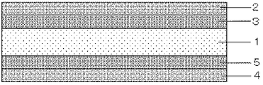
本発明の記録媒体は、支持体と、該支持体の第一面側及び第一面側と該支持体を挟んで反対側の第二面側に、各々2層以上のインク受容層を有する記録媒体である。本発明の記録媒体の一例を、図1に示す。支持体1の第一面側には、最外層のインク受容層2と、最外層のインク受容層2に隣接したインク受容層3が存在する。また、第一面側と該支持体を挟んで反対側の第二面側には、最外層のインク受容層4と、最外層のインク受容層4に隣接したインク受容層5が存在する。即ち、支持体の表面と裏面であわせて4層以上のインク受容層を有していることになるが、これらのインク受容層はいずれも顔料及びバインダーを含有する。
The recording medium of the present invention has a support, and two or more ink receiving layers on each of the first surface side of the support and the first surface side and the second surface opposite to the support. It is a recording medium. An example of the recording medium of the present invention is shown in FIG. On the first surface side of the support 1, there is an outermost ink receiving layer 2 and an ink receiving layer 3 adjacent to the outermost ink receiving layer 2. Further, an outermost ink receiving layer 4 and an ink receiving
支持体の第一面側における最外層のインク受容層の細孔半径のピーク位置をA1nm、最外層のインク受容層に隣接したインク受容層の細孔半径のピーク位置をA2nmとする。さらに、第二面側における最外層のインク受容層の細孔半径のピーク位置をB1nm、最外層のインク受容層に隣接したインク受容層の細孔半径のピーク位置をB2nmとする。このとき、本発明の記録媒体は、A1、A2、B1、B2が下記関係式(1)、(2)を満たすことを特徴とする。
(1) A1>A2
(2) B1>B2
The peak position of the pore radius of the outermost ink receiving layer on the first surface side of the support is A 1 nm, and the peak position of the pore radius of the ink receiving layer adjacent to the outermost ink receiving layer is A 2 nm. To do. Further, the peak position of the pore radius of the outermost ink receiving layer on the second surface side is B 1 nm, and the peak position of the pore radius of the ink receiving layer adjacent to the outermost ink receiving layer is B 2 nm. . At this time, the recording medium of the present invention is characterized in that A 1 , A 2 , B 1 and B 2 satisfy the following relational expressions (1) and (2).
(1) A 1 > A 2
(2) B 1 > B 2
本発明の記録媒体は、支持体の両面(第一面及び第二面)に各々2層以上のインク受容層が存在し、その最外層のインク受容層の細孔半径のピーク位置が、最外層に隣接したインク受容層の細孔半径のピーク位置よりも大きい構成となっている。この結果、最外層のインク受容層にインクが付与されると、インク中の水分等は、毛細管力によって最外層のインク受容層に隣接したインク受容層へ引っ張られるので、最外層のインク受容層に残留しにくくなる。最外層のインク受容層に存在する水分等が少ないと、インク受容層を重ねた場合でも、インク受容層間での水分等の移動する量が低減し、画像の白モヤの発生を抑制することができる。 In the recording medium of the present invention, two or more ink receiving layers each exist on both surfaces (first surface and second surface) of the support, and the peak position of the pore radius of the outermost ink receiving layer is the outermost layer. The ink receiving layer adjacent to the outer layer is configured to be larger than the peak position of the pore radius. As a result, when ink is applied to the outermost ink receiving layer, moisture and the like in the ink is pulled to the ink receiving layer adjacent to the outermost ink receiving layer by capillary force, so the outermost ink receiving layer It becomes difficult to remain in. If there is little moisture etc. present in the outermost ink receiving layer, even when the ink receiving layers are stacked, the amount of moisture etc. moving between the ink receiving layers will be reduced, and the occurrence of white haze in the image will be suppressed. it can.
一方、最外層のインク受容層と最外層のインク受容層に隣接したインク受容層の細孔半径のピーク位置に差が無い、または隣接したインク受容層の細孔半径のピーク位置の方が大きい場合を考える。この場合には、最外層のインク受容層が持つ細孔の毛細管力が、隣接したインク受容層のインク受容層の持つ細孔の毛細管力と同等若しくは小さくなる。そのため、記録後に、最外層のインク受容層に存在する水分等の、最外層のインク受容層に隣接したインク受容層(下層)への移動が起こりにくくなり、最外層のインク受容層に水分等が残留しやすくなる。よって、インク受容層を重ねた場合に、画像の白モヤが発生する場合がある。 On the other hand, there is no difference in the peak position of the pore radius between the outermost ink receiving layer and the ink receiving layer adjacent to the outermost ink receiving layer, or the peak position of the pore radius of the adjacent ink receiving layer is larger Think about the case. In this case, the capillary force of the pores of the outermost ink receiving layer is equal to or smaller than the capillary force of the pores of the ink receiving layer of the adjacent ink receiving layer. Therefore, after recording, moisture and the like present in the outermost ink receiving layer are less likely to move to the ink receiving layer (lower layer) adjacent to the outermost ink receiving layer. Tends to remain. Therefore, when the ink receiving layer is overlapped, white fogging of the image may occur.
尚、本発明の記録媒体は、上述の効果を損なわない範囲であれば、最外層の上に液を塗布したり、或いは別の層を設けてもよい。 In the recording medium of the present invention, a liquid may be applied on the outermost layer or another layer may be provided as long as the above effects are not impaired.
A1、A2、B1、B2は、上記(1)及び(2)の関係を満たせばよいが、より良好に白モヤの発生を抑制するには、A1−A2>2.0、B1−B2>2.0の関係を満たすことが好ましい。さらに好ましくは、A1−A2>4.0である。また、B1−B2>4.0である。 A 1 , A 2 , B 1 , and B 2 may satisfy the relationship (1) and (2) above, but in order to better suppress the occurrence of white haze, A 1 -A 2 > 2. It is preferable to satisfy the relationship of 0, B 1 -B 2 > 2.0. More preferably, A 1 -A 2 > 4.0. In addition, a B 1 -B 2> 4.0.
上述のような層構成にすることによって、水分等の大部分は、最外層のインク受容層から隣接したすぐ下のインク受容層へと移動する。しかしながら、これだけでは全ての水分等は移動せず、わずかながら最外層のインク受容層に残留することが推測される。そこで、本発明の記録媒体は、A1、B1がさらに下記(3)の関係を満たすことを特徴としている。
(3) |A1−B1|≦1.0
By employing the layer configuration as described above, most of moisture and the like move from the outermost ink receiving layer to the adjacent ink receiving layer immediately below. However, it is presumed that all the moisture and the like do not move by this alone, but remain slightly in the outermost ink receiving layer. Therefore, the recording medium of the present invention is characterized in that A 1 and B 1 further satisfy the following relationship (3).
(3) | A 1 −B 1 | ≦ 1.0
A1、B1が(3)の関係を満たすことで、インク受容層同士を重ねた場合に、(1)及び(2)による最外層の水分等の低減と相まって、最外層のインク受容層に残留した水分等の移動を低減し、白モヤの発生を抑制することができる。好ましくは、|A1−B1|≦0.5である。|A1−B1|が1.0を超えると、重なり合うインク受容層間の細孔半径の差が大きくなり、インク受容層間の毛細管力の差が大きくなる傾向となる。このため、最外層のインク受容層に残留した水分等の移動が、細孔半径のピーク位置が小さいインク受容層側に起こり、これにより白モヤが発生する場合がある。 When A 1 and B 1 satisfy the relationship of (3), when the ink receiving layers are overlapped with each other, the outermost ink receiving layer is coupled with the reduction of moisture in the outermost layer according to (1) and (2). It is possible to reduce the movement of moisture and the like remaining on the surface and suppress the occurrence of white haze. Preferably, | A 1 −B 1 | ≦ 0.5. When | A 1 −B 1 | exceeds 1.0, the difference in pore radius between the overlapping ink receiving layers increases, and the difference in capillary force between the ink receiving layers tends to increase. For this reason, the movement of moisture or the like remaining in the outermost ink receiving layer occurs on the ink receiving layer side where the peak position of the pore radius is small, which may cause white fog.
以上のような各層の細孔半径のピーク位置の制御は、従来公知の方法、即ち各層に用いる顔料を適宜選択したり、各層の顔料とバインダーの比率を調整することで達成できる。 The control of the peak position of the pore radius of each layer as described above can be achieved by a conventionally known method, that is, by appropriately selecting the pigment used in each layer or adjusting the ratio of the pigment to the binder in each layer.
本発明の記録媒体は、第一面側の最外層のインク受容層及び第二面側の最外層のインク受容層が、JIS B0601で規定される算術平均粗さRaが0.5μm以上であることを特徴とする。算術平均粗さRaが0.50μm以上であれば、インク受容層の表面に凹凸が存在するため、記録後にインク受容層同士が重なった場合でも、インク受容層同士の接触面積を小さくできる。そのため、上記(1)、(2)及び(3)の関係と相まって、インク受容層間でのインク中の水分等の移動が起こりにくくなり、白モヤを低減させることが可能となる。算術平均粗さRaは、0.70μm以上であることが好ましい。算術平均粗さRaは、0.50μm以上であれば、特に上限はなく本発明の効果を得ることが可能であるが、記録後の画像濃度、画像品位の点からは、2.00μm以下であることが好ましい。 In the recording medium of the present invention, the outermost ink receiving layer on the first surface side and the outermost ink receiving layer on the second surface side have an arithmetic average roughness Ra defined by JIS B0601 of 0.5 μm or more. It is characterized by that. If the arithmetic average roughness Ra is 0.50 μm or more, irregularities exist on the surface of the ink receiving layer, so that even when the ink receiving layers overlap after recording, the contact area between the ink receiving layers can be reduced. Therefore, coupled with the relationships (1), (2) and (3) above, it becomes difficult for moisture and the like in the ink to move between the ink receiving layers, and it is possible to reduce white fog. The arithmetic average roughness Ra is preferably 0.70 μm or more. The arithmetic average roughness Ra is not particularly limited as long as it is 0.50 μm or more, and the effects of the present invention can be obtained. However, in terms of image density and image quality after recording, it is 2.00 μm or less. Preferably there is.
インク受容層の算術平均粗さの調整は、従来公知の方法で行えばよい。例えば、数平均粒子径が1〜20μmの無機、有機粒子を添加する方法、インク受容層表面に微細な凹凸を彫刻する方法や、規則的、または不規則な形状の凹凸を有する支持体上にインク受容層を設ける方法等が挙げられる。凹凸を有する支持体上にインク受容層を設ける方法は、支持体表面に予め規則的または不規則な形状の型付け処理を行っておき、この上にインク受容層を設けることで、インク受容層表面に支持体と同様の形状の凹凸を持たせる方法である。この方法は、インク受容層が堅い多孔質皮膜である場合に好ましい。この方法に好ましく用いられる支持体は、両面をポリオレフィンで被覆された紙支持体である。予め、ポリオレフィン樹脂表面に凹凸を型付けする代表的な方法としては、支持体上に溶融したポリオレフィン樹脂を押し出しコーティングした後、型付けローラーに圧接して微細な凹凸の模様付けを行う方法が挙げられる。模様付けを行う方法には、溶融押し出しで得られる樹脂コート紙に室温付近でエンボシングカレンダー処理する方法や、ポリオレフィン樹脂の押し出しコーティング時にロール表面に模様を彫刻したクーリングロールを使用して冷却しながら凹凸を形成する方法がある。比較的弱い圧力で型付けすることができ、かつより正確で均質な型付けができる点で、後者が好ましい。予め凹凸を表面に設けた支持体にインク受容層用塗工液を塗工して得られる記録媒体の場合、支持体の表面の粗さはインク受容層の表面の凹凸の高低差より高くすることが必要である。従って、支持体のJIS B0601に規定される中心線平均粗さRaは0.70μm以上であることが好ましい。また、Raは0.90μm以上であることがより好ましい。 The arithmetic average roughness of the ink receiving layer may be adjusted by a conventionally known method. For example, a method of adding inorganic or organic particles having a number average particle diameter of 1 to 20 μm, a method of engraving fine irregularities on the surface of the ink receiving layer, or a support having irregularities of regular or irregular shapes Examples thereof include a method of providing an ink receiving layer. The method of providing the ink receiving layer on the support having irregularities is that the surface of the ink receiving layer is previously formed on the surface of the support, and the ink receiving layer is provided on the surface. This is a method in which the surface is provided with irregularities having the same shape as the support. This method is preferred when the ink receiving layer is a rigid porous film. The support preferably used in this method is a paper support coated on both sides with polyolefin. As a typical method for forming irregularities on the surface of the polyolefin resin in advance, there is a method in which a melted polyolefin resin is extrusion coated on a support, and then pressed into a shaping roller to form a fine uneven pattern. For patterning, resin coated paper obtained by melt extrusion is embossed with a calendar near room temperature, or cooled using a cooling roll engraved with a pattern on the roll surface during polyolefin resin extrusion coating. There is a method of forming irregularities. The latter is preferred in that it can be molded with a relatively weak pressure and can be more accurately and homogeneously molded. In the case of a recording medium obtained by applying a coating liquid for an ink receiving layer to a support provided with irregularities on the surface in advance, the roughness of the surface of the support is made higher than the level difference of the irregularities on the surface of the ink receiving layer. It is necessary. Accordingly, the center line average roughness Ra defined in JIS B0601 of the support is preferably 0.70 μm or more. Ra is more preferably 0.90 μm or more.
尚、本発明の記録媒体は、記録を行う為に付与するインクの色材が染料である場合に、より良好に白モヤの発生を抑制することができる。 The recording medium of the present invention can more effectively suppress the occurrence of white smear when the color material of ink applied for recording is a dye.
<支持体>
本発明で用いられる支持体としては、例えば、フィルム、キャストコート紙、バライタ紙、レジンコート紙(両面がポリオレフィン等の樹脂で被覆された樹脂皮膜紙)等の紙類が好ましい。フィルムとしては、ポリエチレン、ポリプロピレン、ポリエステル、ポリ乳酸、ポリスチレン、ポリアセテート、ポリ塩化ビニル、酢酸セルロース、ポリエチレンテレフタレート、ポリメチルメタクリレート、ポリカーボネート等の透明な熱可塑性樹脂フィルムが挙げられる。
<Support>
As the support used in the present invention, for example, paper such as film, cast coated paper, baryta paper, resin coated paper (resin-coated paper coated on both sides with a resin such as polyolefin) is preferable. Examples of the film include transparent thermoplastic resin films such as polyethylene, polypropylene, polyester, polylactic acid, polystyrene, polyacetate, polyvinyl chloride, cellulose acetate, polyethylene terephthalate, polymethyl methacrylate, and polycarbonate.
これら以外にも、適度なサイジングが施された紙である無サイズ紙やコート紙、無機物の充填若しくは微細な発泡により不透明化されたフィルムからなるシート状物質(合成紙等)を用いてもよい。また、ガラス又は金属等からなるシートを用いてもよい。さらに、支持体とインク受容層との接着強度を向上させるため、支持体の表面にコロナ放電処理や各種アンダーコート処理を施してもよい。 In addition to these, non-sized paper or coated paper that is appropriately sized paper, sheet-like substances (synthetic paper, etc.) made of a film made opaque by filling with inorganic substances or fine foaming may be used. . A sheet made of glass or metal may be used. Furthermore, in order to improve the adhesive strength between the support and the ink receiving layer, the surface of the support may be subjected to corona discharge treatment or various undercoat treatments.
これら支持体の中でも、インク受容層形成後の記録媒体の光沢感や、表面の凹凸形状を形成しやすい点から、レジンコート紙を用いることが好ましい。 Among these supports, it is preferable to use resin-coated paper from the viewpoint that the glossiness of the recording medium after the ink receiving layer is formed and the surface unevenness shape can be easily formed.
<インク受容層>
本発明の記録媒体は、支持体の第一面側及び第二面側に、各々2層以上のインク受容層を有する。これらのインク受容層は顔料及びバインダーを含有する。
<Ink receiving layer>
The recording medium of the present invention has two or more ink receiving layers on the first side and the second side of the support. These ink receiving layers contain a pigment and a binder.
(顔料)
顔料としては、例えば以下の無機顔料や有機顔料が挙げられる。無機顔料としては、軽質炭酸カルシウム、重質炭酸カルシウム、炭酸マグネシウム、カオリン、ケイ酸アルミニウム、珪藻土、ケイ酸カルシウム、ケイ酸マグネシウム。合成非晶質シリカ、コロイダルシリカ、アルミナ、アルミナ水和物、水酸化マグネシウム等が挙げられる。有機顔料としては、スチレン系プラスチックピグメント、アクリル系プラスチックピグメント、ポリエチレン粒子、マイクロカプセル粒子、尿素樹脂粒子、メラミン樹脂粒子等が挙げられる。顔料は、上記無機顔料、有機顔料の中から1種、又は必要に応じて選択された2種以上を組み合わせて用いることができる。
(Pigment)
Examples of the pigment include the following inorganic pigments and organic pigments. Inorganic pigments include light calcium carbonate, heavy calcium carbonate, magnesium carbonate, kaolin, aluminum silicate, diatomaceous earth, calcium silicate, and magnesium silicate. Examples thereof include synthetic amorphous silica, colloidal silica, alumina, alumina hydrate, and magnesium hydroxide. Examples of organic pigments include styrene plastic pigments, acrylic plastic pigments, polyethylene particles, microcapsule particles, urea resin particles, and melamine resin particles. The pigment can be used alone or in combination of two or more selected from the above-mentioned inorganic pigments and organic pigments.
以上の顔料の中でも、画像の白モヤの発生を良好に抑制できる点で、アルミナ水和物を用いることが好ましい。アルミナ水和物としては、例えば、下記一般式(X)により表されるものを好適に利用できる。
Al2O3−n(OH)2n・mH2O・・・・(X)
(上記式中、nは0、1、2又は3の何れかを表し、mは0〜10、好ましくは0〜5の範囲にある値を表す。但し、mとnは同時に0にはならない。mH2Oは、多くの場合、結晶格子の形成に関与しない脱離可能な水相を表すものであるため、mは整数又は整数でない値をとることができる。又、この種の材料を加熱するとmは0の値に達することがあり得る)。
Among the above pigments, it is preferable to use alumina hydrate from the viewpoint that the occurrence of white haze in the image can be satisfactorily suppressed. As an alumina hydrate, what is represented by the following general formula (X) can be used suitably, for example.
Al 2 O 3-n (OH ) 2n · mH 2 O ···· (X)
(In the above formula, n represents any of 0, 1, 2, or 3, and m represents a value in the range of 0 to 10, preferably 0 to 5. However, m and n are not 0 at the same time. MH 2 O often represents a detachable aqueous phase that is not involved in the formation of the crystal lattice, so m can take an integer or non-integer value. When heated, m can reach a value of 0).
アルミナ水和物の結晶構造としては、熱処理する温度に応じて、非晶質、キブサイト型、ベーマイト型の水酸化アルミニウムが知られており、アルミナ水和物、これらのうち、何れの結晶構造のものも使用可能である。これらの中でも、X線回折法による分析でベーマイト構造、又は非晶質を示すアルミナ水和物が好ましい。 As the crystal structure of alumina hydrate, amorphous, kibsite-type, and boehmite-type aluminum hydroxides are known depending on the temperature at which heat treatment is performed. Things can also be used. Among these, an alumina hydrate that exhibits a boehmite structure or an amorphous state by analysis by an X-ray diffraction method is preferable.
また、アルミナ水和物は、インク受容層形成時の各インク受容層の細孔半径のピーク位置が、7.0nm以上13.0nm以下となるものを用いることが好ましい。インク受容層の細孔半径のピーク位置がこの範囲内にあることによって、優れたインク吸収性及び発色性を発揮することが可能となる。インク受容層の細孔半径のピーク位置が7.0nmよりも小さいと、インク吸収性が不足して、アルミナ水和物に対するバインダーの量を調整したとしても、十分なインク吸収性が得ることができない場合がある。特に、最外層のインク受容層に隣接するインク受容層において、細孔半径のピークが7.0nmよりも小さいと、インク吸収性が不十分になりやすい傾向がある。 As the alumina hydrate, it is preferable to use an alumina hydrate in which the peak position of the pore radius of each ink receiving layer is 7.0 nm or more and 13.0 nm or less. When the peak position of the pore radius of the ink receiving layer is within this range, it is possible to exhibit excellent ink absorbability and color developability. If the peak position of the pore radius of the ink receiving layer is smaller than 7.0 nm, the ink absorbability is insufficient, and even if the amount of the binder with respect to the alumina hydrate is adjusted, sufficient ink absorbability can be obtained. There are cases where it is not possible. In particular, in the ink receiving layer adjacent to the outermost ink receiving layer, if the peak of the pore radius is smaller than 7.0 nm, the ink absorbability tends to be insufficient.
一方、インク受容層の細孔半径のピーク位置が13.0nmよりも大きくなると、インク受容層のヘイズが大きくなり、良好な発色性が得られない場合がある。特に最外層のインク受容層において、細孔半径のピークが13.0nmよりも大きいと、記録後にインク中の発色成分が存在する層のヘイズが大きくなり、良好な発色性が得られにくい傾向がある。 On the other hand, if the peak position of the pore radius of the ink receiving layer is larger than 13.0 nm, the haze of the ink receiving layer increases, and good color developability may not be obtained. In particular, in the outermost ink-receiving layer, if the peak of the pore radius is larger than 13.0 nm, the haze of the layer in which the coloring component in the ink is present after recording tends to increase, and it tends to be difficult to obtain good color development. is there.
各インク受容層の細孔容積は、インク吸収性の点から0.50ml/g以上であることが好ましい。さらに、インク受容層の細孔半径として、25.0nm以上の細孔が実質的に存在しないことが好ましい。25.0nm以上の細孔が存在する場合には、インク受容層のヘイズが大きくなり、良好な発色性が得られない場合がある。 The pore volume of each ink receiving layer is preferably 0.50 ml / g or more from the viewpoint of ink absorbability. Further, it is preferable that the pore diameter of the ink receiving layer is substantially free of pores of 25.0 nm or more. When pores having a diameter of 25.0 nm or more are present, the haze of the ink receiving layer increases, and good color developability may not be obtained.
尚、本発明における細孔半径のピーク位置及び細孔容積とは、記録媒体を窒素吸着脱離法によって測定した、窒素ガスの吸着脱離等温線よりBJH(Barrett−Joyner−Halenda)法を用いて求めた値である。記録媒体を窒素吸着脱離法にて測定する場合、インク受容層以外の部分(支持体、樹脂被膜層等)でも測定が行われることとなるが、インク受容層以外の部分は、窒素吸着脱離法で一般的に測定可能な1〜100nmの範囲に実質的に細孔を持っていない。このため、記録媒体全体を窒素吸着脱離法で測定した場合には、インク受容層の平均細孔半径を測定していることと実質的に同じとなる。このことは、例えば主としてパルプからなる支持体や、主としてパルプからなる支持体の両面を樹脂で被覆したレジンコート紙の細孔分布を、窒素吸着脱離法で測定した場合に、1〜100nmの間に実質的に細孔を有していないことから明らかである。 In the present invention, the peak position of the pore radius and the pore volume are determined by using the BJH (Barrett-Joyner-Halenda) method based on the adsorption / desorption isotherm of nitrogen gas measured by the nitrogen adsorption / desorption method of the recording medium. This is the value obtained. When the recording medium is measured by the nitrogen adsorption / desorption method, the measurement is also performed on portions other than the ink receiving layer (support, resin coating layer, etc.). There is substantially no pore in the range of 1 to 100 nm, which can be generally measured by a separation method. For this reason, when the entire recording medium is measured by the nitrogen adsorption / desorption method, it is substantially the same as measuring the average pore radius of the ink receiving layer. This means that, for example, when the pore distribution of a resin-coated paper in which both sides of a support mainly made of pulp and a support mainly made of pulp are coated with a resin is measured by a nitrogen adsorption / desorption method, it is 1 to 100 nm. It is clear from the fact that there are substantially no pores in between.
尚、本発明の記録媒体は、第一面側、第二面側のいずれの面においても2層以上のインク受容層を有する。各層の細孔半径のピーク位置及び細孔容積は、支持体に各層を形成したものを層の種類毎に用意し、上述の窒素吸着脱離法によって測定する。 The recording medium of the present invention has two or more ink receiving layers on both the first surface side and the second surface side. The peak position of the pore radius and the pore volume of each layer are measured by the above-described nitrogen adsorption / desorption method by preparing each layer on the support for each layer type.
各層に2つ以上の細孔半径のピークが存在する場合には、各々の層のピークの極大値の中で最大を示す位置をそれぞれA1、A2、B1、B2とし、上記(1)、(2)及び(3)の関係を満たせばよい。 In the case where two or more pore radius peaks exist in each layer, the maximum position among the maximum values of the peak of each layer is defined as A 1 , A 2 , B 1 , B 2 , respectively ( What is necessary is just to satisfy | fill the relationship of 1), (2), and (3).
インク受容層形成時に、上述のようなアルミナ水和物の細孔半径を得るためには、BET法によるBET比表面積が、100m2/g以上200m2/g以下であるアルミナ水和物を用いることが好ましい。より好ましくは125m2/g以上である。また、175m2/g以下である。尚、BET法とは、気相吸着法による粉体の表面積測定法の一つであり、吸着等温線から1gの試料の持つ総表面積、即ち比表面積を求める方法である。このBET法では、通常、吸着気体として窒素ガスが用いられ、吸着量を被吸着気体の圧又は容積の変化から測定する方法が最も多く用いられる。この際、多分子吸着の等温線を表すものとして最も著名なものは、Brunauer、Emmett、Tellerの式であって、BET式と呼ばれ比表面積決定に広く用いられている。上記BET法では、BET式に基づいて吸着量を求め、吸着分子1個が表面で占める面積を掛けることにより比表面積が得られる。BET法では、窒素吸着脱離法の測定において、ある相対圧力における吸着量の関係を数点測定し、最小二乗法によりそのプロットの傾き、切片を求めることで比表面積を導き出す。このため、測定の精度を上げるためには、相対圧力と吸着量の関係は少なくとも5点測定しておくことが好ましく、より好ましくは10点以上である。 In order to obtain the pore radius of the above-mentioned alumina hydrate when forming the ink receiving layer, an alumina hydrate having a BET specific surface area of 100 m 2 / g or more and 200 m 2 / g or less by the BET method is used. It is preferable. More preferably, it is 125 m 2 / g or more. Moreover, it is 175 m < 2 > / g or less. The BET method is a method for measuring the surface area of a powder by a vapor phase adsorption method, and is a method for obtaining the total surface area, that is, the specific surface area of a 1 g sample from an adsorption isotherm. In this BET method, nitrogen gas is usually used as an adsorbed gas, and the most frequently used method is to measure the amount of adsorption from the change in pressure or volume of the gas to be adsorbed. At this time, the most prominent expression representing the isotherm of multimolecular adsorption is the Brunauer, Emmett, and Teller equation, which is called the BET equation and is widely used for determining the specific surface area. In the BET method, the specific surface area is obtained by calculating the amount of adsorption based on the BET formula and multiplying the area occupied by one adsorbed molecule on the surface. In the BET method, in the nitrogen adsorption / desorption method, the relationship between the adsorption amounts at a certain relative pressure is measured at several points, and the specific surface area is derived by obtaining the slope and intercept of the plot by the least square method. For this reason, in order to increase the accuracy of measurement, it is preferable to measure at least 5 points, more preferably 10 points or more, between the relative pressure and the amount of adsorption.
また、アルミナ水和物は、平板状で、平均アスペクト比が3.0以上10以下、平板面の縦横比が0.60以上1.0以下であるものが好ましい。尚、アスペクト比は、特公平5−16015号公報に記載された方法により求めることができる。即ち、アスペクト比は、粒子の(厚さ)に対する(直径)の比で示される。ここで「直径」とは、アルミナ水和物を顕微鏡又は電子顕微鏡で観察したときの粒子の投影面積と等しい面積を有する円の直径(円相当径)を示す。また、平板面の縦横比は、アスペクト比と同様に、粒子を顕微鏡で観察した場合の、平板面の最小値を示す直径と、最大値を示す直径の比を示す。 The alumina hydrate is preferably flat and has an average aspect ratio of 3.0 to 10 and an aspect ratio of the flat plate surface of 0.60 to 1.0. The aspect ratio can be obtained by the method described in Japanese Patent Publication No. 5-16015. That is, the aspect ratio is represented by the ratio of (diameter) to (thickness) of particles. Here, the “diameter” indicates a diameter (equivalent circle diameter) of a circle having an area equal to the projected area of the particles when the alumina hydrate is observed with a microscope or an electron microscope. Similarly to the aspect ratio, the aspect ratio of the flat plate surface indicates the ratio of the diameter indicating the minimum value of the flat plate surface and the diameter indicating the maximum value when the particles are observed with a microscope.
アスペクト比が上記範囲外となるアルミナ水和物を使用した場合、形成したインク受容層の細孔分布範囲が狭くなる場合がある。このため、アルミナ水和物の粒子径を揃えて製造するのが困難になる場合がある。また、同様に、縦横比が上記範囲外のものを使用した場合も、インク受容層の細孔径分布が狭くなる。 When alumina hydrate having an aspect ratio outside the above range is used, the pore distribution range of the formed ink receiving layer may be narrowed. For this reason, it may be difficult to produce the alumina hydrate with the same particle size. Similarly, when a material having an aspect ratio outside the above range is used, the pore diameter distribution of the ink receiving layer becomes narrow.
アルミナ水和物には、繊毛状と、繊毛状でない形状のものがあることが知られている。本発明者の知見によれば、同じアルミナ水和物であっても、平板状のアルミナ水和物の方が、繊毛状のアルミナ水和物よりも分散性がよい。また、繊毛状のアルミナ水和物は、塗工時に支持体の表面に対して平行に配向し形成される細孔が小さくなって、インク受容層のインク吸収性が小さくなることがある。これに対して、平板状のアルミナ水和物は、塗工により配向する傾向が小さく形成されるインク受容層の細孔の大きさやインク吸収性へ影響を及ぼしにくい。このため、平板状のアルミナ水和物を用いることが好ましい。 It is known that alumina hydrate has ciliary and non-ciliated shapes. According to the knowledge of the present inventor, even with the same alumina hydrate, the plate-like alumina hydrate has better dispersibility than the ciliated alumina hydrate. In addition, cilia-like alumina hydrate may have small pores formed by being oriented parallel to the surface of the support during coating, and the ink absorbability of the ink receiving layer may be reduced. On the other hand, the plate-like alumina hydrate hardly affects the size of the pores and the ink absorbability of the ink receiving layer formed with a small tendency to be oriented by coating. For this reason, it is preferable to use a plate-like alumina hydrate.
(バインダー)
本発明で用いられるバインダーとしては、例えば、以下のものが挙げられる。即ち、酸化澱粉、エーテル化澱粉、リン酸エステル化澱粉等の澱粉誘導体。カルボキシメチルセルロース、ヒドロキシエチルセルロース等のセルロース誘導体。カゼイン、ゼラチン、大豆蛋白、ポリビニルアルコール又はその誘導体。ポリビニルピロリドン、無水マレイン酸樹脂、スチレン−ブタジエン共重合体、メチルメタクリレート−ブタジエン共重合体等の共役重合体ラテックス。アクリル酸エステル及びメタクリル酸エステルの重合体等のアクリル系重合体ラテックス。エチレン−酢酸ビニル共重合体等のビニル系重合体ラテックス。上記の各種重合体のカルボキシル基等の官能基含有単量体による官能基変性重合体ラテックス。カチオン基を用いて上記各種重合体をカチオン化したもの、カチオン性界面活性剤を用いて上記各種重合体の表面をカチオン化したもの。カチオン性ポリビニルアルコール下で上記各種重合体を重合し、重合体の表面にポリビニルアルコールを分布させたもの。カチオン性コロイド粒子の懸濁分散液中で上記各種重合体の重合を行い、重合体の表面にカチオン性コロイド粒子を分布させたもの。メラミン樹脂、尿素樹脂等の熱硬化合成樹脂等の水性バインダー。ポリメチルメタクリレート等のアクリル酸エステルやメタクリル酸エステルの重合体又は共重合体樹脂。ポリウレタン樹脂、不飽和ポリエステル樹脂、塩化ビニル−酢酸ビニルコポリマー、ポリビニルブチラール、アルキッド樹脂等の合成樹脂系バインダー。
(binder)
Examples of the binder used in the present invention include the following. That is, starch derivatives such as oxidized starch, etherified starch, and phosphate esterified starch. Cellulose derivatives such as carboxymethyl cellulose and hydroxyethyl cellulose. Casein, gelatin, soy protein, polyvinyl alcohol or derivatives thereof. Conjugated polymer latex such as polyvinylpyrrolidone, maleic anhydride resin, styrene-butadiene copolymer, methyl methacrylate-butadiene copolymer. Acrylic polymer latex such as acrylic ester and methacrylic ester polymers. Vinyl polymer latex such as ethylene-vinyl acetate copolymer. Functional group-modified polymer latex with functional group-containing monomers such as carboxyl groups of the above various polymers. What cationized the said various polymers using the cationic group, What cationized the surface of the said various polymers using the cationic surfactant. A polymer obtained by polymerizing the above-mentioned various polymers under cationic polyvinyl alcohol and distributing the polyvinyl alcohol on the surface of the polymer. The above-mentioned various polymers are polymerized in a suspension dispersion of cationic colloidal particles, and the cationic colloidal particles are distributed on the surface of the polymer. Aqueous binders such as thermosetting synthetic resins such as melamine resin and urea resin. Polymers or copolymer resins of acrylic acid esters and methacrylic acid esters such as polymethyl methacrylate. Synthetic resin binders such as polyurethane resin, unsaturated polyester resin, vinyl chloride-vinyl acetate copolymer, polyvinyl butyral, alkyd resin.
これらのバインダーは、単独で、又は複数種を混合して用いることができる。中でも最も好ましいバインダーとして、ポリビニルアルコールが挙げられる。ポリビニルアルコールの中でも、ポリ酢酸ビニルを加水分解して得られる通常のポリビニルアルコールが好ましい。ポリビニルアルコールは、平均重合度が1500以上のものが好ましく用いられる。中でも、平均重合度が2000以上5000以下のものがより好ましい。また、ケン化度は80以上100以下のものが好ましく、85以上100以下のものがより好ましい。 These binders can be used alone or in combination of two or more. Among these, the most preferred binder is polyvinyl alcohol. Among polyvinyl alcohols, ordinary polyvinyl alcohol obtained by hydrolyzing polyvinyl acetate is preferable. Polyvinyl alcohol having an average degree of polymerization of 1500 or more is preferably used. Among these, those having an average degree of polymerization of 2000 or more and 5000 or less are more preferable. The degree of saponification is preferably from 80 to 100, more preferably from 85 to 100.
また、この他に、末端をカチオン変性したポリビニルアルコールや、アニオン性基を有するアニオン変性ポリビニルアルコール等の変性ポリビニルアルコールを使用することができる。 In addition to these, modified polyvinyl alcohols such as polyvinyl alcohols whose ends are cationically modified and anionic modified polyvinyl alcohols having an anionic group can be used.
インク受容層中の、バインダーと顔料との質量比は、バインダー/顔料が1/10以上10/1以下であることが好ましい。さらに、バインダー/顔料が1/5以上5/1以下であることがより好ましい。 The binder / pigment mass ratio of the binder and the pigment in the ink receiving layer is preferably 1/10 or more and 10/1 or less. Further, the binder / pigment is more preferably 1/5 or more and 5/1 or less.
(その他の材料)
本発明では、必要に応じて、インク受容層が下記の材料を含有してもよい。
(Other materials)
In the present invention, the ink receiving layer may contain the following materials as required.
例えば、インク受容層には、ホウ酸及びホウ酸塩の少なくとも一方を含有してもよい。ホウ酸及びホウ酸塩を添加することにより、インク受容層内でのクラックの発生を抑制することができる。ホウ酸としては、オルトホウ酸(H3BO3)、メタホウ酸、次ホウ酸等が挙げられる。ホウ酸塩は、上記ホウ酸の水溶性の塩であることが好ましい。具体的には、下記のホウ酸のアルカリ土類金属塩等を挙げることができる。ホウ酸のナトリウム塩(Na2B4O7・10H2O、NaBO2・4H2O等)、ホウ酸のカリウム塩(K2B4O7・5H2O、KBO2等)等のアルカリ金属塩。ホウ酸のアンモニウム塩(NH4B4O9・3H2O、NH4BO2等)。ホウ酸のマグネシウム塩やカルシウム塩。これらのホウ酸等の中でも、塗工液の経時安定性と、クラック発生の抑制効果の点からオルトホウ酸を用いることが好ましい。また、ホウ酸等の使用量としては、上層、下層中のバインダーに対して、ホウ酸固形分10質量%以上50.0質量%以下の範囲で用いることが好ましい。上記範囲を超えると塗工液の経時安定性が低下する場合がある。すなわち、インク吸収性記録媒体を生産する際、塗工液を長時間に渡って使用することとなり、ホウ酸の含有量が多いとその間に塗工液の粘度の上昇や、ゲル化物の発生が起こる場合がある。このため、塗工液の交換やコーターヘッドの清掃等を頻繁に行なうことが必要となり、生産性が著しく低下してしまう。更に、上記範囲を超えると、インク受容層に均質で良好な光沢面が得られない場合がある。尚、ホウ酸等の使用量が上記範囲内であっても、製造条件等によっては、インク受容層内にクラックが発生する場合があるため、適当な使用量の範囲を選択する必要がある。 For example, the ink receiving layer may contain at least one of boric acid and borate. By adding boric acid and borate, the occurrence of cracks in the ink receiving layer can be suppressed. Examples of boric acid include orthoboric acid (H 3 BO 3 ), metaboric acid, and hypoboric acid. The borate is preferably a water-soluble salt of boric acid. Specific examples include the following alkaline earth metal salts of boric acid. Alkaline such as sodium salt of boric acid (Na 2 B 4 O 7 · 10H 2 O, NaBO 2 · 4H 2 O, etc.), potassium salt of boric acid (K 2 B 4 O 7 · 5H 2 O, KBO 2 etc.) Metal salt. Ammonium salts of boric acid (NH 4 B 4 O 9 · 3H 2 O, NH 4 BO 2 , etc.). Magnesium and calcium salts of boric acid. Among these boric acids and the like, it is preferable to use orthoboric acid from the viewpoint of the temporal stability of the coating solution and the effect of suppressing the occurrence of cracks. Moreover, as usage-amounts, such as a boric acid, it is preferable to use in boric acid solid content 10 mass% or more and 50.0 mass% or less with respect to the binder in an upper layer and a lower layer. When the above range is exceeded, the temporal stability of the coating solution may be lowered. That is, when producing an ink-absorbing recording medium, the coating liquid is used for a long time, and when the content of boric acid is large, the viscosity of the coating liquid increases and the generation of a gelled product occurs. May happen. For this reason, it is necessary to frequently change the coating liquid, clean the coater head, and the like, and the productivity is significantly reduced. Furthermore, if the above range is exceeded, a uniform and good glossy surface may not be obtained in the ink receiving layer. Even if the amount of boric acid used is within the above range, cracks may occur in the ink receiving layer depending on the manufacturing conditions and the like, so it is necessary to select an appropriate amount range.
この他に、インク受容層は、染料定着剤として、カチオンポリマーに代表されるカチオン性物質を含有してもよい。カチオンポリマーは、特に、インク受容層中でのマゼンタ染料の染着性を向上させ、アントラピリドン系及びキナクリドン系に代表されるマゼンタ染料の高温多湿下でのインクの滲み出し(マイグレーション)を抑制することができる。 In addition, the ink receiving layer may contain a cationic substance typified by a cationic polymer as a dye fixing agent. In particular, the cationic polymer improves the dyeing property of the magenta dye in the ink receiving layer, and suppresses the migration of the ink under high temperature and high humidity of the magenta dye represented by the anthrapyridone type and the quinacridone type. be able to.
インク受容層形成用の塗工液中には、pH調整剤として、例えば、下記の酸又は塩を適宜添加してもよい。即ち、蟻酸、酢酸、グリコール酸、シュウ酸、プロピオン酸、マロン酸、コハク酸、アジピン酸、マレイン酸、リンゴ酸、酒石酸、クエン酸、安息香酸、フタル酸。イソフタル酸、テレフタル酸、グルタル酸、グルコン酸、乳酸、アスパラギン酸、グルタミン酸、ピメリン酸、スベリン酸、メタンスルホン酸。塩酸、硝酸、燐酸等の無機酸。上記酸の塩等である。アルミナ水和物を水中に分散させるためには、一塩基酸を用いることが好ましい。このため、上記pH調整剤の中でも、蟻酸、酢酸、グリコール酸、メタンスルホン酸等の有機酸や、塩酸、硝酸等を用いることが好ましい。また、その他の塗工液用の添加剤として、顔料分散剤、増粘剤、流動性改良剤、消泡剤、抑泡剤、界面活性剤、離型剤、浸透剤、着色顔料、着色染料を添加してもよい。また、蛍光増白剤、紫外線吸収剤、酸化防止剤、防腐剤、防黴剤、耐水化剤、硬化剤、耐候材料等を添加してもよい。 In the coating liquid for forming the ink receiving layer, for example, the following acids or salts may be appropriately added as a pH adjuster. That is, formic acid, acetic acid, glycolic acid, oxalic acid, propionic acid, malonic acid, succinic acid, adipic acid, maleic acid, malic acid, tartaric acid, citric acid, benzoic acid, phthalic acid. Isophthalic acid, terephthalic acid, glutaric acid, gluconic acid, lactic acid, aspartic acid, glutamic acid, pimelic acid, suberic acid, methanesulfonic acid. Inorganic acids such as hydrochloric acid, nitric acid, phosphoric acid. And salts of the above acids. In order to disperse the alumina hydrate in water, it is preferable to use a monobasic acid. For this reason, it is preferable to use organic acids, such as formic acid, acetic acid, glycolic acid, and methanesulfonic acid, hydrochloric acid, nitric acid, etc. among the said pH adjusters. Other additives for coating liquids include pigment dispersants, thickeners, fluidity improvers, antifoaming agents, antifoaming agents, surfactants, mold release agents, penetrants, colored pigments, colored dyes May be added. Moreover, you may add a fluorescent whitening agent, a ultraviolet absorber, antioxidant, antiseptic | preservative, an antifungal agent, a water-proofing agent, a hardening | curing agent, a weatherproof material, etc.
<インク受容層用塗工液の塗工方法>
インク受容層を形成するための塗工液の塗工は、オンマシン、オフマシン等で、各種カーテンコーター、エクストルージョン方式を用いたコーター、スライドホッパー方式を用いたコーター等で行えばよい。塗工時には、塗工液の粘度調製等を目的として、塗工液を加温してもよく、コーターヘッドを加温してもよい。塗工後の塗工液の乾燥は、例えば、直線トンネル乾燥機、アーチドライヤー、エアループドライヤー、サインカーブエアフロートドライヤー等の熱風乾燥機を用いて行うことが好ましい。また、赤外線、加熱ドライヤー、マイクロ波等を利用した乾燥機等を、適宜、選択して用いてもよい。
<Coating method of ink receiving layer coating liquid>
The coating liquid for forming the ink receiving layer may be applied on-machine, off-machine, etc. by various curtain coaters, coaters using an extrusion method, coaters using a slide hopper method, or the like. At the time of coating, the coating liquid may be heated or the coater head may be heated for the purpose of adjusting the viscosity of the coating liquid. The coating liquid after coating is preferably dried using a hot air dryer such as a straight tunnel dryer, an arch dryer, an air loop dryer, or a sine curve air float dryer. In addition, a dryer using infrared rays, a heated dryer, a microwave, or the like may be appropriately selected and used.
インク受容層の塗工量としては、インクの吸収性が満足できるものであれば特に制限はされないが、最外層のインク受容層の塗工量については、10.0g/m2以下であることが好ましい。最外層のインク受容層の塗工量が10.0g/m2以下であれば、インク受容層にインクが印刷された際に、インク中の水分等が、最外層のインク受容層に隣接したインク受容層に速やかに移動し、白モヤの発生を効果的に抑制することができる。 The coating amount of the ink receiving layer is not particularly limited as long as the ink absorptivity is satisfactory, but the coating amount of the outermost ink receiving layer is 10.0 g / m 2 or less. Is preferred. If the coating amount of the outermost ink receiving layer is 10.0 g / m 2 or less, when ink is printed on the ink receiving layer, moisture in the ink is adjacent to the outermost ink receiving layer. It can move quickly to the ink receiving layer and effectively suppress the occurrence of white fog.
以下、実施例、比較例を示し、本発明をさらに具体的に説明するが、本発明はこれらに限定されるものではない。尚、以下に「部」または「%」とあるのは、特に断らない限り質量基準である。 EXAMPLES Hereinafter, although an Example and a comparative example are shown and this invention is demonstrated further more concretely, this invention is not limited to these. In the following description, “part” or “%” is based on mass unless otherwise specified.
<記録媒体の製造方法>
(支持体の作成)
軽質炭酸カルシウム20部を、広葉樹晒クラフトパルプ100部のスラリー中に添加し、カチオン澱粉2部、無水アルケニルコハク酸系中性サイズ剤0.3部を添加し、十分に混合して抄紙原料とした。次に、長網多筒式抄紙機を用いて水分を10%まで乾燥させ、サイズプレスで酸化澱粉の7%溶液を両面で4g/m2塗工、乾燥し、水分7%まで乾燥させて坪量120g/m2の基紙を作成した。作成した基紙の表裏両方の面に、高密度ポリエチレン70部と低密度ポリエチレン20部からなる樹脂組成物を、20.0g/m2の塗工量となるように溶融押し出し塗布した。直後に、表面に種々の不規則の形状の凹凸を有するクーリングロールを使用して、冷却しながらポリエチレン表面に4種類の型付け処理を行った。型付けの違いは密度及び凹凸の高さを調整することで行った。このようにして、坪量160g/m2の支持体A、B、C、Dを作成した。
<Method for manufacturing recording medium>
(Create support)
Add 20 parts of light calcium carbonate into a slurry of 100 parts of hardwood bleached kraft pulp, add 2 parts of cationic starch, 0.3 part of an alkenyl succinic anhydride neutral sizing agent, mix well, and did. Next, the moisture was dried to 10% using a long mesh multi-cylinder paper machine, and a 7% solution of oxidized starch was coated on both sides with a size press at 4 g / m 2 and dried to a moisture content of 7%. A base paper having a basis weight of 120 g / m 2 was prepared. A resin composition composed of 70 parts of high-density polyethylene and 20 parts of low-density polyethylene was melt-extruded and applied to both the front and back surfaces of the prepared base paper so that the coating amount was 20.0 g / m 2 . Immediately after that, using a cooling roll having irregularities of various irregular shapes on the surface, four types of molding treatments were performed on the polyethylene surface while cooling. The difference in the molding was made by adjusting the density and the height of the unevenness. In this way, Supports A, B, C and D having a basis weight of 160 g / m 2 were prepared.
各支持体の算術平均表面粗さRaを測定した。測定は、各支持体を測定に適した大きさに切り分け、SURFCOM 1500DX(東京精密製)を用い、JIS B0601に規定された方法を用いて行った。測定の結果、各支持体の算術平均表面粗さRaは、支持体Aが0.59μm、支持体Bが0.72μm、支持体Cが0.95μm、支持体Dが2.10μmであった。 The arithmetic average surface roughness Ra of each support was measured. The measurement was carried out using the method defined in JIS B0601, using each support in a size suitable for measurement and using SURFCOM 1500DX (manufactured by Tokyo Seimitsu). As a result of the measurement, the arithmetic average surface roughness Ra of each support was 0.59 μm for the support A, 0.72 μm for the support B, 0.95 μm for the support C, and 2.10 μm for the support D. .
(インク受容層用塗工液1の作成)
イオン交換水中314.7部に、無水酢酸2.0部を添加し、十分攪拌したのち、無機微粒子としてアルミナ水和物(Disperal HP18:SASOL製)を100部添加し、十分攪拌し、コロイダルゾルを得た。得られたコロイダルゾルをアルミナ水和物が22%となるように適宜イオン交換水で希釈し、コロイダルゾルを得た。
(Preparation of coating liquid 1 for ink receiving layer)
After adding 2.0 parts of acetic anhydride to 314.7 parts of ion-exchanged water and stirring sufficiently, 100 parts of alumina hydrate (Disperal HP18: manufactured by SASOL) is added as inorganic fine particles, stirring sufficiently, and colloidal sol Got. The obtained colloidal sol was appropriately diluted with ion-exchanged water so that the alumina hydrate was 22% to obtain a colloidal sol.
一方、ポリビニルアルコール(PVA235、重合度:3500、ケン化度:88%:クラレ製)をイオン交換水中に溶解させて、固形分8.0%のポリビニルアルコール水溶液を得た。そして、得られたポリビニルアルコール溶液を、上記で調製したコロイダルゾルに、アルミナ水和物の固形分に対して、ポリビニルアルコール固形分換算((バインダー)/(アルミナ水和物)×100)が10%となるように混合した。次に、3.0%ホウ酸水溶液を、アルミナ水和物の固形分に対してホウ酸固形分換算で1.5%となるように混合して、インク受容層用塗工液1を得た。 On the other hand, polyvinyl alcohol (PVA235, polymerization degree: 3500, saponification degree: 88%: manufactured by Kuraray Co., Ltd.) was dissolved in ion-exchanged water to obtain a polyvinyl alcohol aqueous solution having a solid content of 8.0%. Then, the obtained polyvinyl alcohol solution was converted into the colloidal sol prepared above in terms of polyvinyl alcohol solid content ((binder) / (alumina hydrate) × 100) in terms of the solid content of alumina hydrate. It mixed so that it might become%. Next, a 3.0% boric acid aqueous solution is mixed with the solid content of the alumina hydrate so as to be 1.5% in terms of boric acid solid content, thereby obtaining the ink receiving layer coating liquid 1. It was.
(インク受容層用塗工液2の作成)
インク受容層用塗工液1の作成のアルミナ水和物(Disperal HP18)をアルミナ水和物(Disperal HP14:SASOL製)に変えた以外は、インク受容層用塗工液1の作成と同様にして、インク受容層用塗工液2を得た。
(Preparation of ink receiving layer coating liquid 2)
Except for changing the alumina hydrate (Disperal HP18) in the preparation of the ink receiving layer coating liquid 1 to the alumina hydrate (Dispersal HP14: manufactured by SASOL), the same procedure as in the preparation of the ink receiving layer coating liquid 1 was performed. Thus, an ink receiving layer coating solution 2 was obtained.
(インク受容層用塗工液3の作成)
インク受容層用塗工液1の作成のアルミナ水和物(Disperal HP18)をアルミナ水和物(Disperal HP10:SASOL製)に変えた以外は、インク受容層用塗工液1の作成と同様にして、インク受容層用塗工液3を得た。
(Preparation of ink receiving layer coating liquid 3)
Except for changing the alumina hydrate (Disperal HP18) in the preparation of the ink receiving layer coating liquid 1 to the alumina hydrate (Dispersal HP10: manufactured by SASOL), the same procedure as in the preparation of the ink receiving layer coating liquid 1 was performed. Thus, an ink receiving layer coating solution 3 was obtained.
(インク受容層用塗工液4の作成)
シリカ(A300:日本アエロジル製)100部、カチオンポリマー(シャロールDC902P:第一工業製薬製)4部を、固形分濃度が18%となるように水に分散し、さらに高圧ホモジナイザーで分散してシリカ分散液を得た。
(Preparation of coating solution 4 for ink receiving layer)
Silica (A300: Nippon Aerosil Co., Ltd.) 100 parts and cationic polymer (Charol DC902P: Daiichi Kogyo Seiyaku Co., Ltd.) 4 parts are dispersed in water so that the solid concentration is 18%, and further dispersed with a high-pressure homogenizer. A dispersion was obtained.
一方、ポリビニルアルコール(PVA235、重合度:3500、ケン化度:88%:クラレ製)をイオン交換水中に溶解させて、固形分8.0%のポリビニルアルコール水溶液を得た。そして、得られたポリビニルアルコール溶液を、上記で調製したコロイダルゾルに、シリカの固形分に対して、ポリビニルアルコール固形分換算((バインダー)/(シリカ)×100)が15%となるように混合した。次に、3.0%ホウ酸水溶液を、シリカの固形分に対してホウ酸固形分換算で2.3%となるように混合して、インク受容層用塗工液4を得た。 On the other hand, polyvinyl alcohol (PVA235, polymerization degree: 3500, saponification degree: 88%: manufactured by Kuraray Co., Ltd.) was dissolved in ion-exchanged water to obtain a polyvinyl alcohol aqueous solution having a solid content of 8.0%. Then, the obtained polyvinyl alcohol solution is mixed with the colloidal sol prepared above so that the solid content of the silica is equivalent to 15% in terms of the solid content of the polyvinyl alcohol ((binder) / (silica) × 100). did. Next, a 3.0% boric acid aqueous solution was mixed with the solid content of silica so as to be 2.3% in terms of solid content of boric acid to obtain a coating liquid 4 for ink receiving layer.
(インク受容層用塗工液5の作成)
前記インク受容層用塗工液2とインク受容層用塗工液3とを、Disperal HP14とDisperal HP10が固形分比で40:60となるように混合し、インク受容層用塗工液5を得た。
(Preparation of
The ink receiving layer coating liquid 2 and the ink receiving layer coating liquid 3 are mixed so that Dispersal HP14 and Dispersal HP10 are in a solid content ratio of 40:60, and the ink receiving
(インク受容層用塗工液6の作成)
前記インク受容層用塗工液1とインク受容層用塗工液2とを、Disperal HP18とDisperal HP14が固形分比で20:80となるように混合し、インク受容層用塗工液6を得た。
(Preparation of ink receiving layer coating liquid 6)
The ink receiving layer coating liquid 1 and the ink receiving layer coating liquid 2 are mixed so that Dispersal HP18 and Dispersal HP14 have a solid content ratio of 20:80, and the ink receiving layer coating liquid 6 is prepared. Obtained.
(インク受容層用塗工液7の作成)
前記インク受容層用塗工液2と、インク受容層用塗工液3とを、Disperal HP14とDisperal HP10が固形分比で70:30となるように混合し、インク受容層用塗工液7を得た。
(Preparation of ink receiving layer coating solution 7)
The ink receiving layer coating liquid 2 and the ink receiving layer coating liquid 3 are mixed so that Dispersal HP14 and Dispersal HP10 are in a solid content ratio of 70:30, and the ink receiving layer coating liquid 7 is used. Got.
(インク受容層用塗工液8の作成)
前記インク受容層用塗工液1と、インク受容層用塗工液2とを、Disperal HP18とDisperal HP14が固形分比で90:10となるように混合し、インク受容層用塗工液8を得た。
(Preparation of coating liquid 8 for ink receiving layer)
The ink receiving layer coating liquid 1 and the ink receiving layer coating liquid 2 are mixed so that Dispersal HP18 and Dispersal HP14 have a solid content ratio of 90:10, and the ink receiving layer coating liquid 8 is mixed. Got.
(インク受容層用塗工液9の作成)
前記インク受容層用塗工液1と、インク受容層用塗工液2とを、Disperal HP18とDisperal HP14が固形分比で70:30となるように混合し、インク受容層用塗工液9を得た。
(Preparation of ink receiving layer coating liquid 9)
The ink receiving layer coating liquid 1 and the ink receiving layer coating liquid 2 are mixed so that Dispersal HP18 and Dispersal HP14 have a solid content ratio of 70:30, and the ink receiving layer coating liquid 9 is mixed. Got.
(インク受容層用塗工液10の作成)
前記インク受容層用塗工液2と、インク受容層用塗工液3とを、Disperal HP14とDisperal HP10が固形分比で80:20となるように混合し、インク受容層用塗工液10を得た。
(Preparation of coating liquid 10 for ink receiving layer)
The ink receiving layer coating liquid 2 and the ink receiving layer coating liquid 3 are mixed so that Dispersal HP14 and Dispersal HP10 have a solid content ratio of 80:20, and the ink receiving layer coating liquid 10 is mixed. Got.
(インク受容層用塗工液11の作成)
前記インク受容層用塗工液1と、インク受容層用塗工液2とを、Disperal HP18とDisperal HP14が固形分比で60:40となるように混合し、インク受容層用塗工液11を得た。
(Preparation of coating liquid 11 for ink receiving layer)
The ink receiving layer coating liquid 1 and the ink receiving layer coating liquid 2 are mixed so that Dispersal HP18 and Dispersal HP14 have a solid content ratio of 60:40, and the ink receiving layer coating liquid 11 is mixed. Got.
<細孔半径のピーク位置の測定>
支持体Aの第一面(表面)側に、各々のインク受容層用塗工液を乾燥後の塗工量が30.0g/m2となるように塗布した。塗工液の塗工は、スライドダイを用いて40℃で行った。次に、これを60℃で乾燥して、細孔半径のピーク位置測定用の記録媒体を作成した。作成した記録媒体のインク受容層の細孔半径のピーク位置を、下記の装置を用いて測定した。
・細孔半径の測定:自動比表面積/細孔分布測定装置 TriStar3000(島津製作所製)
・サンプル前処理:バキュプレップ061(島津製作所製)
記録媒体を5.0×10.0cmのサイズに断裁した後、これを細孔半径測定用の3/8inセルに入る大きさに切り分けた。この後、断裁した記録媒体をセルに投入し、バキュプレップ061を用いて、80℃に加熱しながら20millitorr以下になるまで脱気乾燥を行った。脱気乾燥を行ったサンプルを、TriStar3000を用いて、窒素吸着脱離法により細孔径分布の測定を行った。測定後、得られた窒素脱離側のデータを用いて、最終的に細孔半径のピーク位置の値を得た。測定結果を表1に示す。
<Measurement of peak position of pore radius>
On the first surface (front surface) side of the support A, each ink-receiving layer coating solution was applied such that the coating amount after drying was 30.0 g / m 2 . The coating solution was applied at 40 ° C. using a slide die. Next, this was dried at 60 ° C. to prepare a recording medium for measuring the peak position of the pore radius. The peak position of the pore radius of the ink receiving layer of the prepared recording medium was measured using the following apparatus.
・ Measurement of pore radius: Automatic specific surface area / pore distribution measuring device TriStar 3000 (manufactured by Shimadzu Corporation)
Sample pretreatment: Bacuprep 061 (manufactured by Shimadzu Corporation)
The recording medium was cut to a size of 5.0 × 10.0 cm, and then cut into a size that could fit in a 3/8 inch cell for pore radius measurement. Thereafter, the cut recording medium was put into a cell, and degassed and dried using a Bacuprep 061, while heating to 80 ° C. until it became 20 millitorr or less. The pore diameter distribution of the sample that had been deaerated and dried was measured by a nitrogen adsorption / desorption method using TriStar 3000. After the measurement, finally, the value of the peak position of the pore radius was obtained using the obtained data on the nitrogen desorption side. The measurement results are shown in Table 1.

(実施例1)
支持体Cの第一面側(表面側)に、塗工液3を乾燥後の塗工量が30.0g/m2になるように塗工し、60℃で乾燥を行い、第一面側下層となるインク受容層を設けた。次に、支持体Cの第二面側(裏面側)に、塗工液3を乾燥後の塗工量が30.0g/m2になるように塗工し、60℃で乾燥を行い、第二面側下層となるインク受容層を設けた。
Example 1
On the first surface side (front surface side) of the support C, the coating liquid 3 is applied so that the coating amount after drying is 30.0 g / m 2 and dried at 60 ° C. An ink receiving layer serving as a side lower layer was provided. Next, on the second surface side (back surface side) of the support C, the coating liquid 3 is applied so that the coating amount after drying is 30.0 g / m 2 , and dried at 60 ° C., An ink receiving layer serving as a lower layer on the second surface side was provided.
次に、第一面側に作成したインク受容層上に、塗工液1を乾燥後の塗工量が10.0g/m2になるように塗工し、60℃で乾燥を行い、第一面側上層となるインク受容層を設けた。また、第二面側に作成したインク受容層上に、塗工液1を乾燥後の塗工量が10.0g/m2となるように塗工し、60℃で乾燥を行い、第二面側上層となるインク受容層を設けた。このようにして、記録媒体1を得た。尚、各塗工液の塗工は、スライドダイを用いて40℃で行った。 Next, on the ink receiving layer prepared on the first surface side, the coating liquid 1 is applied so that the coating amount after drying is 10.0 g / m 2 , dried at 60 ° C., An ink receiving layer serving as an upper layer on one side was provided. Further, on the ink receiving layer prepared on the second surface side, the coating liquid 1 is applied so that the coating amount after drying is 10.0 g / m 2 and dried at 60 ° C. An ink receiving layer serving as a surface-side upper layer was provided. In this way, a recording medium 1 was obtained. In addition, application | coating of each coating liquid was performed at 40 degreeC using the slide die.
(実施例2〜25)
支持体の種類、塗工液の種類及び塗工量を表2に示した通りにした以外は実施例1と同様にして、記録媒体2〜25を得た。
(Examples 2 to 25)
Recording media 2 to 25 were obtained in the same manner as in Example 1 except that the type of support, the type of coating liquid, and the coating amount were as shown in Table 2.
(比較例1〜4)
支持体の種類、塗工液の種類及び塗工量を表2に示した通りにした以外は実施例1と同様にして記録媒体26〜29を得た。
(Comparative Examples 1-4)
Recording media 26 to 29 were obtained in the same manner as in Example 1 except that the type of support, the type of coating liquid, and the coating amount were as shown in Table 2.
表2において、第一面側及び第二面側表面の算術平均粗さの測定は、SURFCOM 1500DX(東京精密製)を用い、作成した記録媒体を測定に適した大きさに切り分け、JIS B0601に規定された方法により行った。 In Table 2, the arithmetic average roughness of the first surface side and the second surface side surface was measured using SURFCOM 1500DX (manufactured by Tokyo Seimitsu), and the created recording medium was cut into sizes suitable for measurement, and JIS B0601 Performed by the prescribed method.
<評価>
製造した記録媒体1〜29に対して、以下の評価を行った。
<Evaluation>
The following evaluation was performed on the manufactured recording media 1 to 29.
まず、同じ種類の記録媒体を2枚用意した。次に、このうち一方の記録媒体の第一面側に、インクジェットプリンター(iP8600:キヤノン製)を用い、スーパーフォトペーパーモードで下記画像1を記録した。次に、他方の記録媒体の第二面側に、インクジェットプリンター(iP8600:キヤノン製)を用い、スーパーフォトペーパーモードで下記画像2を記録した。インクは、いずれもBCI−7E(染料インク:キヤノン製)を用いた。
・画像1:15cm×15cmの領域を、PhotoShop7.0のRGBモードで、(R,G,B)=(0,0,0)で塗りつぶした画像。
・画像2:5cm×5cmの領域を、PhotoShop7.0のRGBモードで、(R,G,B)=(255,255,0)で塗りつぶした画像。
First, two sheets of the same type of recording medium were prepared. Next, on the first surface side of one of the recording media, an inkjet printer (iP8600: manufactured by Canon) was used to record the following image 1 in the super photo paper mode. Next, on the second surface side of the other recording medium, an inkjet printer (iP8600: manufactured by Canon) was used to record the following image 2 in the super photo paper mode. As the ink, BCI-7E (dye ink: manufactured by Canon) was used.
Image 1: An image obtained by filling an area of 15 cm × 15 cm with (R, G, B) = (0, 0, 0) in the RGB mode of PhotoShop 7.0.
Image 2: An image obtained by filling a region of 5 cm × 5 cm with (R, G, B) = (255, 255, 0) in the RGB mode of PhotoShop 7.0.
記録後、30分間、23℃、60%RHの環境下で乾燥した。さらに乾燥後、2枚の記録媒体の印字面(インク受容層)を、画像1と画像2が重なるように重ね合わせ、24時間保管した。24時間保管後、画像1における白モヤの発生に関して、下記基準で目視にて評価した。結果は表2に示す。
4:白モヤは発生していない。
3:白モヤがかすかに発生している。
2:白モヤがある程度発生している。
1:白モヤがかなり発生している。
After recording, it was dried for 30 minutes in an environment of 23 ° C. and 60% RH. Further, after drying, the printing surfaces (ink-receiving layers) of the two recording media were overlaid so that image 1 and image 2 overlapped, and stored for 24 hours. After storage for 24 hours, the occurrence of white haze in image 1 was visually evaluated according to the following criteria. The results are shown in Table 2.
4: No white haze has occurred.
3: A white haze is faintly generated.
2: White haze has occurred to some extent.
1: A white haze is considerably generated.
表2から、実施例1〜25の記録媒体は、インク受容層同士を重ねた場合であっても、白モヤの発生が抑制されていることが分かる。 From Table 2, it can be seen that in the recording media of Examples 1 to 25, the occurrence of white haze is suppressed even when the ink receiving layers are overlapped.
一方、比較例1及び4の記録媒体は、A1>A2及びB1>B2となっておらず、白モヤが発生していることが分かる。比較例2の記録媒体は、|A1−B1|≦1.0となっておらず、白モヤが発生していることが分かる。比較例3の記録媒体は、第一面側の最外層のインク受容層及び該第二面側の最外層のインク受容層の算術平均粗さRaが0.5μm以上となっておらず、白モヤが発生していることが分かる。 On the other hand, the recording media of Comparative Examples 1 and 4 do not satisfy A 1 > A 2 and B 1 > B 2, and it can be seen that white haze is generated. In the recording medium of Comparative Example 2, | A 1 −B 1 | ≦ 1.0 is not satisfied, and it can be seen that white haze is generated. In the recording medium of Comparative Example 3, the arithmetic average roughness Ra of the outermost ink receiving layer on the first side and the outermost ink receiving layer on the second side is not 0.5 μm or more, and the white It can be seen that a haze occurs.
Claims (4)
該第一面側及び該第2面側に各々設けられたインク受容層が何れもアルミナ水和物及びバインダーを含有し、
該第一面側における最外層のインク受容層の、細孔分布曲線においてピークを与える細孔半径A1(nm)、最外層のインク受容層に隣接したインク受容層の、細孔分布曲線においてピークを与える細孔半径A2(nm)、該第二面側における最外層のインク受容層の、細孔分布曲線においてピークを与える細孔半径B1(nm)、最外層のインク受容層に隣接したインク受容層の、細孔分布曲線においてピークを与える細孔半径B2(nm)が(1)A1>A2、(2)B1>B2及び(3)|A1−B1|≦1.0を満たし、
該第一面側の最外層のインク受容層のJISB0601で規定される算術平均粗さRaが0.50μm以上であり、且つ、該第二面側の最外層のインク受容層のJISB0601で規定される算術平均粗さRaが0.50μm以上である
ことを特徴とする記録媒体。 A recording medium having two or more ink-receiving layers on each of a support, a first surface side of the support, a first surface side, and a second surface opposite to the support;
Each of the ink receiving layers provided on the first surface side and the second surface side contains an alumina hydrate and a binder,
In the pore distribution curve of the ink receiving layer adjacent to the outermost ink receiving layer, the pore radius A 1 (nm) giving a peak in the pore distribution curve of the outermost ink receiving layer on the first surface side The pore radius A 2 (nm) giving a peak, the pore radius B 1 (nm) giving a peak in the pore distribution curve of the outermost ink receiving layer on the second surface side, and the outermost ink receiving layer The pore radius B 2 (nm) giving a peak in the pore distribution curve of the adjacent ink receiving layer is (1) A 1 > A 2 , (2) B 1 > B 2 and (3) | A 1 -B 1 | ≦ 1.0 is satisfied,
The arithmetic average roughness Ra defined by JISB0601 of the outermost ink receiving layer on the first surface side is 0.50 μm or more, and is defined by JISB0601 of the outermost ink receiving layer on the second surface side. An arithmetic average roughness Ra is 0.50 μm or more.
Priority Applications (6)
| Application Number | Priority Date | Filing Date | Title |
|---|---|---|---|
| JP2010277324A JP5773634B2 (en) | 2010-01-28 | 2010-12-13 | Double-sided recording medium |
| AT10016145T ATE549175T1 (en) | 2010-01-28 | 2010-12-28 | DOUBLE-SIDED RECORDING MEDIUM |
| EP10016145A EP2353880B1 (en) | 2010-01-28 | 2010-12-28 | Double-sided recording medium |
| KR1020110005926A KR101306398B1 (en) | 2010-01-28 | 2011-01-20 | Double-sided recording medium |
| US13/014,641 US8257804B2 (en) | 2010-01-28 | 2011-01-26 | Double-sided recording medium |
| CN2011100306954A CN102189865B (en) | 2010-01-28 | 2011-01-28 | Double-sided recording medium |
Applications Claiming Priority (3)
| Application Number | Priority Date | Filing Date | Title |
|---|---|---|---|
| JP2010017008 | 2010-01-28 | ||
| JP2010017008 | 2010-01-28 | ||
| JP2010277324A JP5773634B2 (en) | 2010-01-28 | 2010-12-13 | Double-sided recording medium |
Publications (3)
| Publication Number | Publication Date |
|---|---|
| JP2011173411A JP2011173411A (en) | 2011-09-08 |
| JP2011173411A5 JP2011173411A5 (en) | 2014-02-06 |
| JP5773634B2 true JP5773634B2 (en) | 2015-09-02 |
Family
ID=43618164
Family Applications (1)
| Application Number | Title | Priority Date | Filing Date |
|---|---|---|---|
| JP2010277324A Active JP5773634B2 (en) | 2010-01-28 | 2010-12-13 | Double-sided recording medium |
Country Status (6)
| Country | Link |
|---|---|
| US (1) | US8257804B2 (en) |
| EP (1) | EP2353880B1 (en) |
| JP (1) | JP5773634B2 (en) |
| KR (1) | KR101306398B1 (en) |
| CN (1) | CN102189865B (en) |
| AT (1) | ATE549175T1 (en) |
Families Citing this family (5)
| Publication number | Priority date | Publication date | Assignee | Title |
|---|---|---|---|---|
| CN102501675A (en) * | 2011-10-14 | 2012-06-20 | 江苏格美高科技发展有限公司 | Matte polypropylene inkjet photo paper suitable for ECO-solvent ink |
| ES2611921T3 (en) * | 2012-06-28 | 2017-05-11 | Canon Kabushiki Kaisha | Print support |
| EP2679396B1 (en) * | 2012-06-28 | 2016-11-30 | Canon Kabushiki Kaisha | Recording medium and image recording process |
| EP2695740B1 (en) * | 2012-08-08 | 2017-09-06 | Canon Kabushiki Kaisha | Recording medium |
| JP6136375B2 (en) | 2013-03-05 | 2017-05-31 | 株式会社リコー | Aqueous ink image forming pretreatment liquid and image forming method |
Family Cites Families (23)
| Publication number | Priority date | Publication date | Assignee | Title |
|---|---|---|---|---|
| JP3045818B2 (en) | 1991-07-10 | 2000-05-29 | ローム株式会社 | Lead wire cutting blade for electrical parts |
| EP0743193A1 (en) * | 1995-05-18 | 1996-11-20 | Canon Kabushiki Kaisha | Printing medium and its use using inkjet printing method |
| JP3913822B2 (en) | 1996-02-22 | 2007-05-09 | セイコーエプソン株式会社 | Inkjet recording sheet and inkjet recording method |
| JP2000141880A (en) * | 1998-11-12 | 2000-05-23 | Keiwa Inc | Perfecting ink jet recording sheet |
| EP1016542B1 (en) * | 1998-12-28 | 2004-03-24 | Canon Kabushiki Kaisha | Recording medium and method of manufacturing the same |
| US6432550B1 (en) | 1999-07-13 | 2002-08-13 | Konica Corporation | Ink-jet recording sheet |
| JP2001080208A (en) | 1999-07-13 | 2001-03-27 | Konica Corp | Ink jet recording sheet |
| JP2001347748A (en) * | 2000-06-09 | 2001-12-18 | Konica Corp | Ink jet recording sheet |
| JP2002307810A (en) * | 2001-04-11 | 2002-10-23 | Asahi Glass Co Ltd | Ink jet recording medium for pigment ink and method for recording the same |
| JP2003159861A (en) * | 2001-11-28 | 2003-06-03 | Mitsubishi Paper Mills Ltd | Recording material for inkjet |
| JP3929379B2 (en) | 2001-11-28 | 2007-06-13 | 三菱製紙株式会社 | Double-sided inkjet recording sheet |
| CA2497751A1 (en) * | 2002-10-01 | 2004-04-15 | Sappi Netherlands Services B.V. | Coated printing sheet and process for making same |
| FR2853916B1 (en) * | 2003-04-17 | 2006-02-24 | Eastman Kodak Co | METHOD FOR IMPROVING THE OZONE STABILITY OF A MATERIAL FOR IMAGING INKJET PRINTING |
| JP2005138403A (en) * | 2003-11-06 | 2005-06-02 | Konica Minolta Holdings Inc | Inkjet recording medium and its production method |
| JP2005225070A (en) * | 2004-02-13 | 2005-08-25 | Oji Paper Co Ltd | Ink jet recording medium |
| US8084107B2 (en) * | 2004-10-20 | 2011-12-27 | Hewlett-Packard Development Company, L.P. | Ink-jet media with multiple porous media coating layers |
| EP1743775A1 (en) * | 2005-07-13 | 2007-01-17 | SAPPI Netherlands Services B.V. | Coated paper for sheet fed offset printing |
| JP2006159755A (en) * | 2004-12-09 | 2006-06-22 | Mitsubishi Paper Mills Ltd | Perfecting inkjet recording medium |
| JP2006175796A (en) | 2004-12-24 | 2006-07-06 | Konica Minolta Photo Imaging Inc | Inkjet recording paper and image forming method using it |
| JP2006247980A (en) * | 2005-03-10 | 2006-09-21 | Mitsubishi Paper Mills Ltd | Inkjet recording material for postcard |
| JP2007290367A (en) * | 2006-03-31 | 2007-11-08 | Canon Inc | Inkjet recording medium, its manufacturing method, and inkjet recording method |
| JP2009125952A (en) * | 2007-11-19 | 2009-06-11 | Fujifilm Corp | Recording medium, its manufacturing method and inkjet recording method |
| JP2010149463A (en) * | 2008-12-26 | 2010-07-08 | Oji Paper Co Ltd | Double-sided inkjet recording material, and its manufacturing method |
-
2010
- 2010-12-13 JP JP2010277324A patent/JP5773634B2/en active Active
- 2010-12-28 EP EP10016145A patent/EP2353880B1/en active Active
- 2010-12-28 AT AT10016145T patent/ATE549175T1/en active
-
2011
- 2011-01-20 KR KR1020110005926A patent/KR101306398B1/en active IP Right Grant
- 2011-01-26 US US13/014,641 patent/US8257804B2/en active Active
- 2011-01-28 CN CN2011100306954A patent/CN102189865B/en active Active
Also Published As
| Publication number | Publication date |
|---|---|
| EP2353880B1 (en) | 2012-03-14 |
| US20110183087A1 (en) | 2011-07-28 |
| ATE549175T1 (en) | 2012-03-15 |
| KR101306398B1 (en) | 2013-09-09 |
| CN102189865B (en) | 2013-10-09 |
| CN102189865A (en) | 2011-09-21 |
| KR20110088399A (en) | 2011-08-03 |
| JP2011173411A (en) | 2011-09-08 |
| EP2353880A1 (en) | 2011-08-10 |
| US8257804B2 (en) | 2012-09-04 |
Similar Documents
| Publication | Publication Date | Title |
|---|---|---|
| JP5106526B2 (en) | Ink jet recording medium and manufacturing method thereof | |
| JP5597163B2 (en) | recoding media | |
| JP5501315B2 (en) | Inkjet recording medium | |
| JP5766024B2 (en) | recoding media | |
| JP5773634B2 (en) | Double-sided recording medium | |
| KR101306497B1 (en) | Recording medium | |
| JP2007055237A (en) | Recording medium | |
| JP5854579B2 (en) | Inkjet recording method | |
| JP2002225423A (en) | Ink jet recording material | |
| US8685504B2 (en) | Recording medium | |
| JP2008265110A (en) | Ink-absorptive recording medium | |
| JP2016064574A (en) | Recording medium | |
| JP2019089324A (en) | Support for recording medium and recording medium | |
| JP2000280603A (en) | Ink jet recording sheet and method for forming record using it | |
| JP2012153123A (en) | Inkjet recording medium | |
| JP5868083B2 (en) | recoding media | |
| JP3685573B2 (en) | Inkjet recording material | |
| JP3869928B2 (en) | Recording medium and ink jet recording method using the recording medium | |
| JP2001277701A (en) | Cut sheet-like ink jet recording medium | |
| JP2011062966A (en) | Inkjet recording medium | |
| JP2011206984A (en) | Recording medium | |
| JP5587074B2 (en) | recoding media | |
| JP2011031471A (en) | Recording medium and manufacturing method therefor | |
| JP2011104866A (en) | Recording medium | |
| JP2011104805A (en) | Recording medium |
Legal Events
| Date | Code | Title | Description |
|---|---|---|---|
| A521 | Request for written amendment filed |
Free format text: JAPANESE INTERMEDIATE CODE: A523 Effective date: 20131213 |
|
| A621 | Written request for application examination |
Free format text: JAPANESE INTERMEDIATE CODE: A621 Effective date: 20131213 |
|
| A977 | Report on retrieval |
Free format text: JAPANESE INTERMEDIATE CODE: A971007 Effective date: 20141112 |
|
| A131 | Notification of reasons for refusal |
Free format text: JAPANESE INTERMEDIATE CODE: A131 Effective date: 20141118 |
|
| A521 | Request for written amendment filed |
Free format text: JAPANESE INTERMEDIATE CODE: A523 Effective date: 20150119 |
|
| TRDD | Decision of grant or rejection written | ||
| A01 | Written decision to grant a patent or to grant a registration (utility model) |
Free format text: JAPANESE INTERMEDIATE CODE: A01 Effective date: 20150602 |
|
| A61 | First payment of annual fees (during grant procedure) |
Free format text: JAPANESE INTERMEDIATE CODE: A61 Effective date: 20150630 |
|
| R151 | Written notification of patent or utility model registration |
Ref document number: 5773634 Country of ref document: JP Free format text: JAPANESE INTERMEDIATE CODE: R151 |