JP5773528B2 - Fluid application device and method - Google Patents
Fluid application device and method Download PDFInfo
- Publication number
- JP5773528B2 JP5773528B2 JP2011544595A JP2011544595A JP5773528B2 JP 5773528 B2 JP5773528 B2 JP 5773528B2 JP 2011544595 A JP2011544595 A JP 2011544595A JP 2011544595 A JP2011544595 A JP 2011544595A JP 5773528 B2 JP5773528 B2 JP 5773528B2
- Authority
- JP
- Japan
- Prior art keywords
- packet
- receptacle
- applicator
- fluid
- base
- Prior art date
- Legal status (The legal status is an assumption and is not a legal conclusion. Google has not performed a legal analysis and makes no representation as to the accuracy of the status listed.)
- Expired - Fee Related
Links
- 239000012530 fluid Substances 0.000 title claims description 105
- 238000000034 method Methods 0.000 title description 18
- 230000007246 mechanism Effects 0.000 claims description 43
- 239000000463 material Substances 0.000 claims description 39
- 239000006260 foam Substances 0.000 claims description 24
- KFZMGEQAYNKOFK-UHFFFAOYSA-N Isopropanol Chemical compound CC(C)O KFZMGEQAYNKOFK-UHFFFAOYSA-N 0.000 claims description 15
- 239000000645 desinfectant Substances 0.000 claims description 14
- LFQSCWFLJHTTHZ-UHFFFAOYSA-N Ethanol Chemical group CCO LFQSCWFLJHTTHZ-UHFFFAOYSA-N 0.000 claims description 13
- 229920003171 Poly (ethylene oxide) Polymers 0.000 claims description 12
- 238000003466 welding Methods 0.000 claims description 11
- 150000003839 salts Chemical class 0.000 claims description 10
- -1 fluorosaran Chemical compound 0.000 claims description 9
- 230000002093 peripheral effect Effects 0.000 claims description 9
- 238000013022 venting Methods 0.000 claims description 9
- 150000004283 biguanides Chemical class 0.000 claims description 7
- 238000004891 communication Methods 0.000 claims description 7
- 239000000853 adhesive Substances 0.000 claims description 6
- 230000001070 adhesive effect Effects 0.000 claims description 6
- 150000001298 alcohols Chemical class 0.000 claims description 6
- 230000002209 hydrophobic effect Effects 0.000 claims description 6
- 239000002736 nonionic surfactant Substances 0.000 claims description 6
- 239000004480 active ingredient Substances 0.000 claims description 5
- ZZQMUJGZCZTLQD-UHFFFAOYSA-N olanexidine Chemical compound CCCCCCCCN=C(N)NC(N)=NCC1=CC=C(Cl)C(Cl)=C1 ZZQMUJGZCZTLQD-UHFFFAOYSA-N 0.000 claims description 5
- 229950001187 olanexidine Drugs 0.000 claims description 5
- 230000000699 topical effect Effects 0.000 claims description 5
- CPKVUHPKYQGHMW-UHFFFAOYSA-N 1-ethenylpyrrolidin-2-one;molecular iodine Chemical compound II.C=CN1CCCC1=O CPKVUHPKYQGHMW-UHFFFAOYSA-N 0.000 claims description 4
- 229920000153 Povidone-iodine Polymers 0.000 claims description 4
- 229960001621 povidone-iodine Drugs 0.000 claims description 4
- 239000004094 surface-active agent Substances 0.000 claims description 4
- CMCBDXRRFKYBDG-UHFFFAOYSA-N 1-dodecoxydodecane Chemical compound CCCCCCCCCCCCOCCCCCCCCCCCC CMCBDXRRFKYBDG-UHFFFAOYSA-N 0.000 claims description 3
- 229920000742 Cotton Polymers 0.000 claims description 3
- 239000004677 Nylon Substances 0.000 claims description 3
- 229920000297 Rayon Polymers 0.000 claims description 3
- YZIYKJHYYHPJIB-UUPCJSQJSA-N chlorhexidine gluconate Chemical compound OC[C@@H](O)[C@@H](O)[C@H](O)[C@@H](O)C(O)=O.OC[C@@H](O)[C@@H](O)[C@H](O)[C@@H](O)C(O)=O.C1=CC(Cl)=CC=C1NC(=N)NC(=N)NCCCCCCNC(=N)NC(=N)NC1=CC=C(Cl)C=C1 YZIYKJHYYHPJIB-UUPCJSQJSA-N 0.000 claims description 3
- 229960003333 chlorhexidine gluconate Drugs 0.000 claims description 3
- 229920001778 nylon Polymers 0.000 claims description 3
- 239000002964 rayon Substances 0.000 claims description 3
- LIJONMBDWKFOLT-IFWQJVLJSA-N 1-[n'-[(3,4-dichlorophenyl)methyl]carbamimidoyl]-2-octylguanidine;(2r,3s,4r,5r)-2,3,4,5,6-pentahydroxyhexanoic acid Chemical compound OC[C@@H](O)[C@@H](O)[C@H](O)[C@@H](O)C(O)=O.CCCCCCCCN=C(N)NC(N)=NCC1=CC=C(Cl)C(Cl)=C1 LIJONMBDWKFOLT-IFWQJVLJSA-N 0.000 claims description 2
- OSDLLIBGSJNGJE-UHFFFAOYSA-N 4-chloro-3,5-dimethylphenol Chemical compound CC1=CC(O)=CC(C)=C1Cl OSDLLIBGSJNGJE-UHFFFAOYSA-N 0.000 claims description 2
- XNCOSPRUTUOJCJ-UHFFFAOYSA-N Biguanide Chemical compound NC(N)=NC(N)=N XNCOSPRUTUOJCJ-UHFFFAOYSA-N 0.000 claims description 2
- 229940123208 Biguanide Drugs 0.000 claims description 2
- 229920002507 Poloxamer 124 Polymers 0.000 claims description 2
- 239000004820 Pressure-sensitive adhesive Substances 0.000 claims description 2
- 229960000686 benzalkonium chloride Drugs 0.000 claims description 2
- UREZNYTWGJKWBI-UHFFFAOYSA-M benzethonium chloride Chemical compound [Cl-].C1=CC(C(C)(C)CC(C)(C)C)=CC=C1OCCOCC[N+](C)(C)CC1=CC=CC=C1 UREZNYTWGJKWBI-UHFFFAOYSA-M 0.000 claims description 2
- 229960001950 benzethonium chloride Drugs 0.000 claims description 2
- CADWTSSKOVRVJC-UHFFFAOYSA-N benzyl(dimethyl)azanium;chloride Chemical compound [Cl-].C[NH+](C)CC1=CC=CC=C1 CADWTSSKOVRVJC-UHFFFAOYSA-N 0.000 claims description 2
- 229960005443 chloroxylenol Drugs 0.000 claims description 2
- 239000006185 dispersion Substances 0.000 claims description 2
- ZFSXZJXLKAJIGS-UHFFFAOYSA-N halocarban Chemical compound C1=C(Cl)C(C(F)(F)F)=CC(NC(=O)NC=2C=CC(Cl)=CC=2)=C1 ZFSXZJXLKAJIGS-UHFFFAOYSA-N 0.000 claims description 2
- 229950006625 halocarban Drugs 0.000 claims description 2
- ACGUYXCXAPNIKK-UHFFFAOYSA-N hexachlorophene Chemical compound OC1=C(Cl)C=C(Cl)C(Cl)=C1CC1=C(O)C(Cl)=CC(Cl)=C1Cl ACGUYXCXAPNIKK-UHFFFAOYSA-N 0.000 claims description 2
- 229960004068 hexachlorophene Drugs 0.000 claims description 2
- 229940093448 poloxamer 124 Drugs 0.000 claims description 2
- 238000009423 ventilation Methods 0.000 claims 2
- NCTHQZTWNVDWGT-UHFFFAOYSA-N 2-hexylbenzene-1,3-diol Chemical class CCCCCCC1=C(O)C=CC=C1O NCTHQZTWNVDWGT-UHFFFAOYSA-N 0.000 claims 1
- 150000002497 iodine compounds Chemical class 0.000 claims 1
- 239000010410 layer Substances 0.000 description 22
- 230000002745 absorbent Effects 0.000 description 10
- 239000002250 absorbent Substances 0.000 description 10
- 239000000243 solution Substances 0.000 description 9
- 239000007788 liquid Substances 0.000 description 6
- 238000007789 sealing Methods 0.000 description 5
- XLYOFNOQVPJJNP-UHFFFAOYSA-N water Substances O XLYOFNOQVPJJNP-UHFFFAOYSA-N 0.000 description 5
- 229920005830 Polyurethane Foam Polymers 0.000 description 3
- 238000004026 adhesive bonding Methods 0.000 description 3
- 229920001400 block copolymer Polymers 0.000 description 3
- 230000000249 desinfective effect Effects 0.000 description 3
- 229910003460 diamond Inorganic materials 0.000 description 3
- 239000010432 diamond Substances 0.000 description 3
- 239000006261 foam material Substances 0.000 description 3
- 230000013011 mating Effects 0.000 description 3
- 229920000642 polymer Polymers 0.000 description 3
- 239000011496 polyurethane foam Substances 0.000 description 3
- 239000011148 porous material Substances 0.000 description 3
- 238000002360 preparation method Methods 0.000 description 3
- 239000002356 single layer Substances 0.000 description 3
- 241000894006 Bacteria Species 0.000 description 2
- LYCAIKOWRPUZTN-UHFFFAOYSA-N Ethylene glycol Chemical compound OCCO LYCAIKOWRPUZTN-UHFFFAOYSA-N 0.000 description 2
- 238000005299 abrasion Methods 0.000 description 2
- 238000010521 absorption reaction Methods 0.000 description 2
- 238000005520 cutting process Methods 0.000 description 2
- 238000009826 distribution Methods 0.000 description 2
- 238000010894 electron beam technology Methods 0.000 description 2
- 210000002615 epidermis Anatomy 0.000 description 2
- 238000001746 injection moulding Methods 0.000 description 2
- 238000010030 laminating Methods 0.000 description 2
- 238000003754 machining Methods 0.000 description 2
- 238000004519 manufacturing process Methods 0.000 description 2
- 229920000728 polyester Polymers 0.000 description 2
- 229920000098 polyolefin Polymers 0.000 description 2
- 230000005855 radiation Effects 0.000 description 2
- 238000007790 scraping Methods 0.000 description 2
- 229940100613 topical solution Drugs 0.000 description 2
- CXIISRLRZRAKST-UHFFFAOYSA-N 29‐(4‐nonylphenoxy)‐3,6,9,12,15,18,21,24,27‐ nonaoxanonacosan‐1‐ol Chemical compound CCCCCCCCCC1=CC=C(OCCOCCOCCOCCOCCOCCOCCOCCOCCOCCO)C=C1 CXIISRLRZRAKST-UHFFFAOYSA-N 0.000 description 1
- WFJIVOKAWHGMBH-UHFFFAOYSA-N 4-hexylbenzene-1,3-diol Chemical compound CCCCCCC1=CC=C(O)C=C1O WFJIVOKAWHGMBH-UHFFFAOYSA-N 0.000 description 1
- 229920001651 Cyanoacrylate Polymers 0.000 description 1
- IAYPIBMASNFSPL-UHFFFAOYSA-N Ethylene oxide Chemical compound C1CO1 IAYPIBMASNFSPL-UHFFFAOYSA-N 0.000 description 1
- 230000004913 activation Effects 0.000 description 1
- 210000000577 adipose tissue Anatomy 0.000 description 1
- 239000012620 biological material Substances 0.000 description 1
- 238000005266 casting Methods 0.000 description 1
- 238000000576 coating method Methods 0.000 description 1
- 150000001875 compounds Chemical class 0.000 description 1
- NLCKLZIHJQEMCU-UHFFFAOYSA-N cyano prop-2-enoate Chemical class C=CC(=O)OC#N NLCKLZIHJQEMCU-UHFFFAOYSA-N 0.000 description 1
- 238000001914 filtration Methods 0.000 description 1
- 239000003292 glue Substances 0.000 description 1
- 230000005484 gravity Effects 0.000 description 1
- 230000002439 hemostatic effect Effects 0.000 description 1
- 229960003258 hexylresorcinol Drugs 0.000 description 1
- 229910052739 hydrogen Inorganic materials 0.000 description 1
- 239000001257 hydrogen Substances 0.000 description 1
- 125000002887 hydroxy group Chemical group [H]O* 0.000 description 1
- WGCNASOHLSPBMP-UHFFFAOYSA-N hydroxyacetaldehyde Natural products OCC=O WGCNASOHLSPBMP-UHFFFAOYSA-N 0.000 description 1
- 238000009434 installation Methods 0.000 description 1
- PNDPGZBMCMUPRI-UHFFFAOYSA-N iodine Chemical compound II PNDPGZBMCMUPRI-UHFFFAOYSA-N 0.000 description 1
- 230000007794 irritation Effects 0.000 description 1
- 239000011159 matrix material Substances 0.000 description 1
- 238000012544 monitoring process Methods 0.000 description 1
- 238000000465 moulding Methods 0.000 description 1
- 229940073555 nonoxynol-10 Drugs 0.000 description 1
- 229920001451 polypropylene glycol Polymers 0.000 description 1
- 230000002028 premature Effects 0.000 description 1
- 238000007493 shaping process Methods 0.000 description 1
- 210000003491 skin Anatomy 0.000 description 1
- 230000001954 sterilising effect Effects 0.000 description 1
- 238000003860 storage Methods 0.000 description 1
- 239000000126 substance Substances 0.000 description 1
- 238000001356 surgical procedure Methods 0.000 description 1
- 208000024891 symptom Diseases 0.000 description 1
- 238000003856 thermoforming Methods 0.000 description 1
- 239000012815 thermoplastic material Substances 0.000 description 1
Images


Classifications
-
- A—HUMAN NECESSITIES
- A61—MEDICAL OR VETERINARY SCIENCE; HYGIENE
- A61M—DEVICES FOR INTRODUCING MEDIA INTO, OR ONTO, THE BODY; DEVICES FOR TRANSDUCING BODY MEDIA OR FOR TAKING MEDIA FROM THE BODY; DEVICES FOR PRODUCING OR ENDING SLEEP OR STUPOR
- A61M35/00—Devices for applying media, e.g. remedies, on the human body
- A61M35/003—Portable hand-held applicators having means for dispensing or spreading integral media
- A61M35/006—Portable hand-held applicators having means for dispensing or spreading integral media using sponges, foams, absorbent pads or swabs as spreading means
-
- A—HUMAN NECESSITIES
- A45—HAND OR TRAVELLING ARTICLES
- A45D—HAIRDRESSING OR SHAVING EQUIPMENT; EQUIPMENT FOR COSMETICS OR COSMETIC TREATMENTS, e.g. FOR MANICURING OR PEDICURING
- A45D34/00—Containers or accessories specially adapted for handling liquid toiletry or cosmetic substances, e.g. perfumes
-
- A—HUMAN NECESSITIES
- A45—HAND OR TRAVELLING ARTICLES
- A45D—HAIRDRESSING OR SHAVING EQUIPMENT; EQUIPMENT FOR COSMETICS OR COSMETIC TREATMENTS, e.g. FOR MANICURING OR PEDICURING
- A45D37/00—Sachet pads specially adapted for liquid toiletry or cosmetic substances
-
- A—HUMAN NECESSITIES
- A61—MEDICAL OR VETERINARY SCIENCE; HYGIENE
- A61M—DEVICES FOR INTRODUCING MEDIA INTO, OR ONTO, THE BODY; DEVICES FOR TRANSDUCING BODY MEDIA OR FOR TAKING MEDIA FROM THE BODY; DEVICES FOR PRODUCING OR ENDING SLEEP OR STUPOR
- A61M35/00—Devices for applying media, e.g. remedies, on the human body
- A61M35/003—Portable hand-held applicators having means for dispensing or spreading integral media
-
- B—PERFORMING OPERATIONS; TRANSPORTING
- B65—CONVEYING; PACKING; STORING; HANDLING THIN OR FILAMENTARY MATERIAL
- B65B—MACHINES, APPARATUS OR DEVICES FOR, OR METHODS OF, PACKAGING ARTICLES OR MATERIALS; UNPACKING
- B65B11/00—Wrapping, e.g. partially or wholly enclosing, articles or quantities of material, in strips, sheets or blanks, of flexible material
- B65B11/04—Wrapping, e.g. partially or wholly enclosing, articles or quantities of material, in strips, sheets or blanks, of flexible material the articles being rotated
-
- B—PERFORMING OPERATIONS; TRANSPORTING
- B65—CONVEYING; PACKING; STORING; HANDLING THIN OR FILAMENTARY MATERIAL
- B65D—CONTAINERS FOR STORAGE OR TRANSPORT OF ARTICLES OR MATERIALS, e.g. BAGS, BARRELS, BOTTLES, BOXES, CANS, CARTONS, CRATES, DRUMS, JARS, TANKS, HOPPERS, FORWARDING CONTAINERS; ACCESSORIES, CLOSURES, OR FITTINGS THEREFOR; PACKAGING ELEMENTS; PACKAGES
- B65D47/00—Closures with filling and discharging, or with discharging, devices
- B65D47/42—Closures with filling and discharging, or with discharging, devices with pads or like contents-applying means
-
- B—PERFORMING OPERATIONS; TRANSPORTING
- B65—CONVEYING; PACKING; STORING; HANDLING THIN OR FILAMENTARY MATERIAL
- B65D—CONTAINERS FOR STORAGE OR TRANSPORT OF ARTICLES OR MATERIALS, e.g. BAGS, BARRELS, BOTTLES, BOXES, CANS, CARTONS, CRATES, DRUMS, JARS, TANKS, HOPPERS, FORWARDING CONTAINERS; ACCESSORIES, CLOSURES, OR FITTINGS THEREFOR; PACKAGING ELEMENTS; PACKAGES
- B65D83/00—Containers or packages with special means for dispensing contents
- B65D83/771—Containers or packages with special means for dispensing contents for dispensing fluent contents by means of a flexible bag or a deformable membrane or diaphragm
-
- A—HUMAN NECESSITIES
- A45—HAND OR TRAVELLING ARTICLES
- A45D—HAIRDRESSING OR SHAVING EQUIPMENT; EQUIPMENT FOR COSMETICS OR COSMETIC TREATMENTS, e.g. FOR MANICURING OR PEDICURING
- A45D34/00—Containers or accessories specially adapted for handling liquid toiletry or cosmetic substances, e.g. perfumes
- A45D2034/005—Containers or accessories specially adapted for handling liquid toiletry or cosmetic substances, e.g. perfumes with a cartridge
-
- A—HUMAN NECESSITIES
- A45—HAND OR TRAVELLING ARTICLES
- A45D—HAIRDRESSING OR SHAVING EQUIPMENT; EQUIPMENT FOR COSMETICS OR COSMETIC TREATMENTS, e.g. FOR MANICURING OR PEDICURING
- A45D2200/00—Details not otherwise provided for in A45D
- A45D2200/10—Details of applicators
- A45D2200/1009—Applicators comprising a pad, tissue, sponge, or the like
- A45D2200/1018—Applicators comprising a pad, tissue, sponge, or the like comprising a pad, i.e. a cushion-like mass of soft material, with or without gripping means
-
- A—HUMAN NECESSITIES
- A45—HAND OR TRAVELLING ARTICLES
- A45D—HAIRDRESSING OR SHAVING EQUIPMENT; EQUIPMENT FOR COSMETICS OR COSMETIC TREATMENTS, e.g. FOR MANICURING OR PEDICURING
- A45D2200/00—Details not otherwise provided for in A45D
- A45D2200/10—Details of applicators
- A45D2200/1009—Applicators comprising a pad, tissue, sponge, or the like
- A45D2200/1036—Applicators comprising a pad, tissue, sponge, or the like containing a cosmetic substance, e.g. impregnated with liquid or containing a soluble solid substance
Landscapes
- Engineering & Computer Science (AREA)
- Health & Medical Sciences (AREA)
- Mechanical Engineering (AREA)
- Animal Behavior & Ethology (AREA)
- Public Health (AREA)
- Heart & Thoracic Surgery (AREA)
- Hematology (AREA)
- Life Sciences & Earth Sciences (AREA)
- Anesthesiology (AREA)
- General Health & Medical Sciences (AREA)
- Biomedical Technology (AREA)
- Veterinary Medicine (AREA)
- Media Introduction/Drainage Providing Device (AREA)
- Application Of Or Painting With Fluid Materials (AREA)
- Containers And Packaging Bodies Having A Special Means To Remove Contents (AREA)
- Apparatus For Disinfection Or Sterilisation (AREA)
- Coating Apparatus (AREA)
- Surgical Instruments (AREA)
Description
本出願は、2008年12月30日に出願された米国特許仮出願第61/141,540号に基づく優先権を主張するものである。 This application claims priority based on US Provisional Application No. 61 / 141,540, filed Dec. 30, 2008.
本出願は、流体塗布のための装置及び方法に関する。 The present application relates to an apparatus and method for fluid application.
種々の医療処置、例えば手術のための患者の準備は、典型的に、医療処置の対象となる領域を清浄にするために、局所溶液(又は流体)、例えば、消毒液の塗布を含む。局所溶液は、スポンジのような材料に溶液をしみ込ませて、手持ち式デバイス、例えば一対の鉗子又は止血鉗子を用いて、しみ込ませたスポンジを対象となる領域にあてることによって、対象となる領域に塗布されることがある。スポンジ又は発泡体材料は、典型的に、開放型の皿又は他の容器内に入れられた流体の中に浸される。 Patient preparation for various medical procedures, eg, surgery, typically involves the application of a topical solution (or fluid), eg, a disinfectant solution, to clean the area that is to be treated. A topical solution can be applied to a target area by immersing the solution in a material such as a sponge and using a hand-held device, such as a pair of forceps or hemostatic forceps, to apply the soaked sponge to the target area. May be applied. The sponge or foam material is typically immersed in a fluid contained in an open dish or other container.
或る事例において、溶液を塗布するのに用いられる既存のデバイスは、種々の欠点を呈する。例えば、典型的なアプリケータは、流体を効果的に保持しないスポンジを使用し、漏れをもたらす。結果として、消毒クリーニングの対象となる領域の準備は、厄介な手順となる。加えて、対象となる領域の外部の領域上への種々の流体の漏れは、刺激、不快、及び/又は他の望ましくない症状を引き起こすかもしれない種々の流体の溜まりにつながる可能性がある。 In some cases, existing devices used to apply solutions exhibit various drawbacks. For example, a typical applicator uses a sponge that does not hold fluid effectively and causes leakage. As a result, the preparation of the area to be disinfected is a cumbersome procedure. In addition, leakage of various fluids on areas outside the area of interest can lead to various fluid pools that may cause irritation, discomfort, and / or other undesirable symptoms.
欠点の別の例は、対象となる領域に所望の分量の流体を分与することの難しさに関係する。流体塗布中に、或る事例において、アプリケータから分与される流体、例えば消毒液の量を制御することが望ましい場合がある。しかしながら、既存のアプリケータは流体を非能率的に分与するため、対象となる領域に正確な量の溶液を送達することは判断が難しい場合がある。これにより、所望されるよりも多い又は少ない溶液が対象となる領域に塗布される場合がある。加えて、典型的なアプリケータは、正確な量の流体を適時に分与することができない発泡体及び/又は流体送達システムを使用する。例えば、流体を貯蔵する内部アンプルを有する或るアプリケータは、流体をスポンジにしみ込ませること、したがって患者への塗布のために利用可能となるまでに時間がかかる。これにより、所望の溶液の予測できない不正確な分与がもたらされる可能性がある。 Another example of a drawback relates to the difficulty of dispensing a desired amount of fluid to the area of interest. During fluid application, in some cases it may be desirable to control the amount of fluid dispensed from the applicator, such as disinfectant. However, because existing applicators dispense fluids inefficiently, it can be difficult to determine to deliver the correct amount of solution to the area of interest. This may cause more or less solution than desired to be applied to the area of interest. In addition, typical applicators use foams and / or fluid delivery systems that cannot dispense the correct amount of fluid in a timely manner. For example, some applicators with internal ampoules that store fluids take time to allow fluid to penetrate the sponge and thus become available for application to the patient. This can lead to unpredictable inaccurate dispensing of the desired solution.
本発明は、流体を塗布するためのアプリケータ・デバイスであって、The present invention is an applicator device for applying a fluid comprising:
近位端及び遠位端を有するハンドルであって、A handle having a proximal end and a distal end,
流体を収容するパケットを受け入れ、且つ前記パケットからの前記流体の排出を容易にするように構成された、前記ハンドルの前記近位端におけるレセプタクル、およびA receptacle at the proximal end of the handle configured to receive a packet containing fluid and facilitate drainage of the fluid from the packet; and
前記パケットを前記レセプタクル内に密封的に包囲するように構成され、且つ外部圧力の印加に応答して歪み、前記レセプタクル内に配置されたときに前記パケットに前記外部圧力を印加してそれにより前記パケットを圧縮し、前記パケットから前記流体を解放することを可能にするように構成された可撓性の蓋であって、前記蓋が、前記蓋に印加された力を分散させるように構成される、蓋、を備えるハンドルと、The packet is configured to hermetically enclose the packet in the receptacle and is distorted in response to application of external pressure to apply the external pressure to the packet when placed in the receptacle, thereby A flexible lid configured to compress a packet and allow the fluid to be released from the packet, wherein the lid is configured to disperse a force applied to the lid. A handle with a lid,
前記解放された流体の流れを向けるように構成され、遠位開口部を含んでいる、前記ハンドルの遠位端におけるベースと、A base at the distal end of the handle configured to direct the released fluid flow and including a distal opening;
前記レセプタクルの内側部分と流体連通する状態で前記ベースと結合されたアプリケータ・パッドであって、前記パッドの一部が前記ベースの前記遠位開口部内に挿入され、前記パッドの一部が前記ベースの前記遠位開口部の外側部分に巻きつけられた、アプリケータ・パッドと、An applicator pad coupled to the base in fluid communication with an inner portion of the receptacle, wherein a portion of the pad is inserted into the distal opening of the base, and a portion of the pad is An applicator pad wrapped around the outer portion of the distal opening of the base;
を備えるアプリケータ・デバイスを提供する。An applicator device comprising:
また、本発明は、流体を塗布するためのアプリケータ・デバイスであって、The present invention also provides an applicator device for applying a fluid,
近位端及び遠位端を有するハンドルであって、A handle having a proximal end and a distal end,
流体を収容するパケットを受け入れ、且つ前記パケットからの前記流体の排出を容易にするように構成された、前記ハンドルの前記近位端におけるレセプタクルであって、前記アプリケータ・デバイスが、前記レセプタクルの中に空気が流れ込む、又は外に空気が流れ出ることを可能にするように構成された少なくとも1つの通気機構を含む、レセプタクル、およびA receptacle at the proximal end of the handle configured to receive a packet containing fluid and facilitate drainage of the fluid from the packet, wherein the applicator device includes a receptacle of the receptacle; A receptacle including at least one venting mechanism configured to allow air to flow into or out of air; and
前記パケットを前記レセプタクル内に密封的に包囲するように構成され、且つ外部圧力の印加に応答して歪み、前記レセプタクル内に配置されたときに前記パケットに前記外部圧力を印加してこれにより前記パケットを圧縮し、前記パケットから前記流体を解放することを可能にするように構成された可撓性の蓋であって、前記通気機構が、前記蓋と前記レセプタクルとの間の接合部において密封されないままにされる領域を備える、蓋、を備えるハンドルと、The packet is configured to hermetically surround the packet within the receptacle and is distorted in response to application of external pressure, thereby applying the external pressure to the packet when placed in the receptacle, thereby A flexible lid configured to compress a packet and allow the fluid to be released from the packet, wherein the venting mechanism is sealed at a junction between the lid and the receptacle A handle comprising a lid with an area left untouched;
前記解放された流体の流れを向けるように構成され、遠位開口部を含んでいる、前記ハンドルの前記遠位端におけるベースと、A base at the distal end of the handle configured to direct the released fluid flow and including a distal opening;
前記ベースの前記遠位開口部を介して前記レセプタクルの内側部分と流体連通する状態で前記ベースと結合されるように構成されたアプリケータ・パッドと、An applicator pad configured to be coupled to the base in fluid communication with an inner portion of the receptacle via the distal opening of the base;
を備えるアプリケータ・デバイスを提供する。An applicator device comprising:
また、本発明は、流体を塗布するためのシステムであって、前記システムは、
流体を収容するパケットであって、
それらの間に前記流体を収容する密封された空間を画定する第1及び第2の対向するパケット側部と、
前記パケットから前記流体を解放するために前記パケットが圧縮されると破壊するように構成された破壊可能領域と、
以前は密封されていた前記空間が実質的に完全につぶされるように、前記パケットが圧縮されると前記パケットの前記第1パケット側部が凸形位置から凹形位置に反転することを可能にする崩壊可能機構と、
を備えるパケットと、
アプリケータ・デバイスであって、
近位端及び遠位端を有するハンドルであって、前記ハンドルの前記近位端にレセプタクルを備え、前記レセプタクルが、前記流体の前記パケットを受け入れ且つ前記パケットからの前記流体の排出を容易にするように構成された、ハンドルと、
前記ハンドルの前記遠位端に配置され、前記解放された流体の流れを向けるように構成され、遠位開口部を含んでいる、ベースと、
前記ベースの前記遠位開口部を介して前記レセプタクルの内側部分と流体連通する状態で前記ベースと結合されるように構成されたアプリケータ・パッドと、
を備えるアプリケータ・デバイスと、
を備え、
前記レセプタクルと前記パケットが、前記パケットを前記レセプタクルに対して配向する、対応する配向機構を有する、システムを提供する。
The present invention is also a system for applying a fluid, the system comprising:
A packet containing a fluid,
First and second opposing packet sides defining a sealed space containing the fluid therebetween,
A breakable region in which the packet is configured to break to be compressed to release the fluid from the front SL packet,
Allows the first packet side of the packet to flip from a convex position to a concave position when the packet is compressed so that the previously sealed space is substantially completely collapsed A collapsible mechanism to
A packet comprising:
An applicator device,
A handle having a proximal end and a distal end, the receptacle comprising a receptacle at the proximal end of the handle, the receptacle receiving the packet of fluid and facilitating drainage of the fluid from the packet Configured with a handle,
A base disposed at the distal end of the handle, configured to direct the released fluid flow, and including a distal opening;
An applicator pad configured to be coupled to the base in fluid communication with an inner portion of the receptacle via the distal opening of the base;
An applicator device comprising:
With
A system is provided wherein the receptacle and the packet have a corresponding orientation mechanism that orients the packet relative to the receptacle.
この出願において、単数形の使用は、特に別の方法で指定しない限り複数形を含む。この出願において、「又は」の使用は、特に明記しない限り「及び/又は」を意味する。さらに、「含んでいる」という用語、並びに「含む」又は「含められる」のような他の形態の使用は、限定するものではない。また、「要素」又は「構成部品」のような用語は、特にそれ以外の指定のない限り、1つのユニットを備えている要素及び構成部品と、1つよりも多くのユニットを備える要素及び構成部品との両方を包含する。 In this application, the use of the singular includes the plural unless specifically stated otherwise. In this application, the use of “or” means “and / or” unless stated otherwise. Further, the use of the term “including” as well as other forms, such as “includes” or “included”, is not limiting. Also, terms such as “element” or “component” unless otherwise specified include elements and components comprising one unit and elements and components comprising more than one unit. Includes both parts.
本明細書で用いられる項見出しは、まとめる目的のためだけのものであって、説明される主題を限定するように解釈されるものではない。特許、特許出願、文献、書籍、及び論文を含むがこれに限定されないこの出願において引用されたすべての文書は、あらゆる目的のためにそれらの全体が参照により明示的に組み込まれる。 The section headings used herein are for organizational purposes only and are not to be construed as limiting the subject matter described. All documents cited in this application, including but not limited to patents, patent applications, literature, books, and articles, are expressly incorporated by reference in their entirety for all purposes.
開示されたアプリケータは、開示されたデバイスを通過し、且つ開示されたデバイスによって分与することを可能にするのに適した粘度をもつ任意の液体を分与する/塗布するように構成されてもよい。幾つかの実施形態において、開示されたアプリケータは、消毒流体を分与する/塗布するのに利用されてもよい。本明細書で用いられる場合の「消毒流体」という用語は、或る実施形態において、種々の医療処置のための準備において領域を清浄にするために用いられてもよい液体のことを指す。 The disclosed applicator is configured to dispense / apply any liquid having a viscosity suitable to allow it to pass through and be dispensed by the disclosed device. May be. In some embodiments, the disclosed applicator may be utilized to dispense / apply disinfect fluid. The term “disinfecting fluid” as used herein refers in some embodiments to a liquid that may be used to clean an area in preparation for various medical procedures.
ここで図面への参照を詳細に行う。可能ならば、同じ又は同様の部分を指すために図面を通して同じ参照番号が用いられるであろう。 Reference will now be made in detail to the drawings. Wherever possible, the same reference numbers will be used throughout the drawings to refer to the same or like parts.
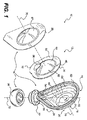
図1は、流体を塗布するためのシステム10の分解図を例証する。図1に示すように、システム10は、流体を収容するように構成されたパケット12を含んでもよい。加えて、システム10は、流体を表面に塗布するように構成されたアプリケータ・デバイス14を含んでもよい。アプリケータ・デバイス14は、ハンドル16を含んでもよい。ハンドル16は、近位端20にレセプタクル18を、及び、遠位端24にベース22を備えてもよい。アプリケータ・デバイス14はまた、ベース22と結合されたアプリケータ・パッド26をも含んでもよい。アプリケータ・デバイス14は、パケット12をレセプタクル18内に包囲するように構成された蓋28をさらに含んでもよい。
FIG. 1 illustrates an exploded view of a
パケット
図1に示すように、パケット12は、近位端30及び遠位端32を含んでもよく、パケット12の遠位端32がハンドル16の遠位端24の方に配向された状態で、レセプタクル18の中に挿入されるように構成されてもよい。パケット12内の流体は、パケット12を(例えば、破壊可能領域において)破裂させて、流体がベース22を通ってアプリケータ・パッド26の中に遠位方向に流れることを可能にする(又は強制する)外力をパケット12に印加することによって吐出されてもよい。
Packet As shown in FIG. 1, the
パケット12は、任意の適切な形状に形成されてもよい。幾つかの実施形態において、パケット12は、付属の図面に示すように、実質的に円形の形状を有してもよい。パケット12は、図示されるように同じく実質的に円形であってもよいレセプタクル18内に嵌り、且つレセプタクル18の形状に概して対応するように構成されてもよい。幾つかの実施形態において、パケット12は、流体塗布システム10の構成部品の組立てを簡単にするために配向機構を含有してもよい。例えば、パケット12は、レセプタクル18の嵌合する形状に対応する形状を有してもよい。幾つかの実施形態において、嵌合する形状は、パケット12をレセプタクル18に対して配向するために非対称であってもよい。
The
パケット12とレセプタクル18とが実質的に円形の嵌合する形状(例えば、図1に示すように)を有する、或る実施形態において、配向機構は、レセプタクル18の実質的に円形の形状から逸脱するレセプタクル18上の構造体と、パケット12の実質的に円形の形状から逸脱するパケット12上の対応する構造体とを含んでもよい。例えば、配向機構は、図1に示すように、レセプタクル18及びパケット12上の対応する突起部のような非対称の形状(涙の滴型の形状を形成する)を含んでもよい。すなわち、幾つかの実施形態において、アプリケータ・デバイス14は、レセプタクル18上の対応するレセプタクル機構34と共に配向されるように構成される、パケット12上のパケット突起部36を含んでもよい。
In certain embodiments where the
涙の滴のような非対称の嵌合する形状は、パケット12とレセプタクル18とがどのようにして互いに位置合わせされるかを容易に分かるようにすることによって組立てを容易にする場合があるだけでなく、パケット12から解放された流体がアプリケータ・パッド26に容易に流れることができるように、パケット12の破壊可能領域がアプリケータ・デバイス14の遠位端の方に配向されることも保証する場合がある。例えば、或る実施形態において、レセプタクル18は、パケット12をパケット突起部36がベース22の方に位置する状態で配向されるように構成されてもよい。こうした実施形態では、パケット突起部36は、パケット12の破壊可能領域を含んでもよい。この破壊可能領域の位置づけ(すなわち、ベース22の方へ向けた)は、破壊可能領域が破れると、例えば、重力により及び/又は流体をパケット12及びレセプタクル18から吐出するためにパケット12を押しつぶすことにより、流体が、パケット12からベース22の方に(ベース22を通って)アプリケータ・パッド26の中に容易に流れることを可能にする場合がある。
An asymmetric mating shape, such as a teardrop, may only facilitate assembly by making it easier to see how the
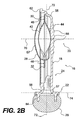
図2Aに示すように、パケット12は、それらの間に流体が充填されてもよい密封された空間40を画定する、対向する側部38を含んでもよい。対向する側部38のいずれか又は両方は、変形可能であってもよい。パケット12内の流体は、パケット12を破裂させて流体がベース22を通ってアプリケータ・パッド26の中に遠位方向に流れることを可能にする(又は強制する)外力をパケット12の対向する側部38に印加することによって吐出されてもよい。
As shown in FIG. 2A, the
パケット12の破壊可能領域は、(例えば、パケット12を押しつぶすこと/圧縮することによって)妥当な活性化力が印加されると壊れて開くように構成されてもよい。破壊可能領域は、ユーザによって力が印加されると壊れて開くように構成されてもよいが、破壊可能領域を含んでいるパケット12は、漏れ又は偶発的に開くことを防止するために、取り扱い、貯蔵などの間は構造的完全性を維持するように構成されてもよい。
The destructible region of the
パケット12は、破壊可能領域を備えた流体保持パケットを形成するのに適した任意のタイプの材料で形成されてもよい。本開示の目的のために、「破壊可能」という用語は、壊れることが可能である、破裂可能である(可撓性パケットの場合のように)、又は他の方法で破壊されるように構成されることを意味するものである。幾つかの実施形態において、破壊可能領域は、パケットの他の部分よりも低い強度を有するように用意されたパケットの一部であってもよい。例えば、或る実施形態において、破壊可能密封は、破壊可能となることが望まれる領域を、最大密封強度のために要求される温度よりも低い温度で密封することによって作り出されてもよい。他の実施形態において、破壊可能密封は、本質的により低い付着性を有する特別に調合された「剥離可能」フィルムを用いて破壊可能領域を形成することによってもたらされてもよい。
The
パケット12は、パケット12が圧縮されるときに一方の側部が他方の側部の中にスムーズに反転することを可能にする両側構成によって自身で排出するものであってもよい。例えば、図2A及び図2Bに示すように、パケット12は、第1パケット側部42と第2パケット側部44とを含んでもよい。第1パケット側部42と第2パケット側部44は、パケット12の周辺部付近の密封部46で互いに密封されてもよい。図2C及び図2Dに示すように、パケット12は、圧縮されると、第1パケット側部42が第2パケット側部44の中に反転し、したがって密封された空間40をつぶすように構成されてもよい。パケット12は、実質的にすべての流体をパケット12から排除するように、完全につぶれる(且つ、幾つかの実施形態においては、つぶれたままとなる)ように構成されてもよい。
The
パケット12は、パケット12が圧縮されると、以前は密封されていた空間40が実質的に完全につぶされるように、パケット12の第1パケット側部42が図2A及び図2Bに示すような凸形位置から図2C及び図2Dに示すような凹形位置に反転することを可能にする崩壊可能機構を含んでもよい。幾つかの実施形態において、パケット12の第1パケット側部42と第2パケット側部44は、異なる厚さのフィルムから形成されてもよい。例えば、幾つかの実施形態において、第1パケット側部42が変形して第1パケット側部42の反転を果たし、それによりパケット12がつぶれることを可能にするために、第1パケット側部42は、第2パケット側部44よりも薄いフィルムで形成されてもよい。
The
代替的に又はそれに加えて、第1パケット側部42は、パケット12の崩壊性を与えるために第2パケット側部44とは異なるサイズ及び/又は形状にされてもよい。例えば、幾つかの実施形態において、第1パケット側部42は、第1中央部48及び第1周辺部50を含んでもよく、第2パケット側部44は、第2中央部52及び第2周辺部54を含んでもよい。第1パケット側部42と第2パケット側部44は、第1周辺部50と第2周辺部54との間の接合部において互いに密封されてもよい。或る実施形態において、第1中央部48は、第2中央部52よりも小さい(例えば、1インチの10分の1又は100分の1のオーダーの)直径を有し、これによって図2C及び図2Dに示すように、崩壊可能機構を形成して第1パケット側部42が第2パケット側部44内に入れ子になることを可能にしてもよい。
Alternatively or in addition, the
或る実施形態において、パケット12内に収容された液体は、活性成分を含有している消毒液であってもよい。種々の消毒液活性成分が当該技術分野では公知であり、エタノール、イソプロピルアルコール、他のアルコール類、及びその組合せ、塩化ベンザルコニウム、塩化ベンゼトニウム、グルコン酸クロルヘキシジン、アルコールを伴うグルコン酸クロルヘキシジン、クロロキシレノール、クロフルカルバン、フルオロサラン、ヘキサクロロフェン、ヘキシルレゾルシノール、ヨウ素を含有する化合物、ポビドンヨード、アルコール、エタノール、イソプロピルアルコール、及び他のアルコール類を伴うポビドンヨード、及びその組合せを含むがこれに限定されない。
In some embodiments, the liquid contained within the
幾つかの実施形態において、例えば米国特許第5,376,686号に開示されるように、消毒液は、活性成分として、ビグアニド誘導体及び/又はその塩、例えば、オラネキシジン[1−(3,4−ジクロロベンジル)−5−オクチルビグアニド]及びその塩を含んでもよい。或る実施形態において、局所消毒薬は、グルコン酸オラネキシジンを含んでもよい。 In some embodiments, for example, as disclosed in US Pat. No. 5,376,686, a disinfectant solution may include, as an active ingredient, a biguanide derivative and / or salt thereof such as olanexidine [1- (3,4). -Dichlorobenzyl) -5-octylbiguanide] and salts thereof. In certain embodiments, the topical disinfectant may include olanexidine gluconate.
消毒液はまた、或る界面活性剤、例えば、ポリオキシエチレンベースの非イオン界面活性剤、及び/又は、アルコール、例えば、エタノール、イソプロピルアルコール、及び他のアルコール類、及び/又は水を、種々の量で組み込んでもよい。有用な界面活性剤は当業者には公知であり、例えば、日本のAsahi Denka Co.,Ltd.、からPolyoxyethylene(20)polyoxypropylene(20)glycolとして入手可能なPoloxamer124(Polyoxypropylene−polyoxyethylene Block Copolymer124としても知られる)、POE(9)ラウリルエーテル(Nikko Chemicals Co.,Ltd.、(日本、東京)から「BL−9EX」として入手可能)、ノノキシノール−10又はNP−10としても知られているPOE(10)ラウリルエーテル(Sanyo Chemical Industries, Ltd.、(日本、京都)から「Emulin NL−100」として入手可能)である。 The disinfectant may also contain certain surfactants, such as polyoxyethylene-based nonionic surfactants, and / or alcohols, such as ethanol, isopropyl alcohol, and other alcohols, and / or water. May be incorporated in an amount of. Useful surfactants are known to those skilled in the art and are described, for example, in Asahi Denka Co., Japan. , Ltd., Ltd. Polyoxyethylene (20) Polyoxypropylene (20) Glycol available from Poloxamer 124 (also known as Polyoxypropylene-polyoxyethylene block Copolymer 124), POE (m.k. BL-9EX ", POE (10) lauryl ether (also known as Nonoxynol-10 or NP-10) (available from Sanyo Chemical Industries, Ltd., Kyoto, Japan) as" Emulin NL-100 " Possible).
或る実施形態において、消毒液は、活性成分とポリオキシエチレンベースの非イオン界面活性剤とを種々の濃度で含んでもよい。幾つかの実施形態において、ポリオキシエチレンに基づく非イオン界面活性剤は、約0.05〜約16%(w/v)の濃度で存在してもよい。 In certain embodiments, the disinfectant solution may include various concentrations of active ingredients and polyoxyethylene-based nonionic surfactants. In some embodiments, the polyoxyethylene-based nonionic surfactant may be present at a concentration of about 0.05 to about 16% (w / v).
或る実施形態において、局所消毒薬は、約0.05〜約5.0%(ビグアニドに基づくw/v)の濃度のビグアニド誘導体、及び/又はその塩を含んでもよい。幾つかの実施形態において、ビグアニド誘導体又はその塩は、オラネキシジン[1−(3,4−ジクロロベンジル)−5−オクチルビグアニド]又はその塩であってもよい。 In certain embodiments, the topical disinfectant may comprise a biguanide derivative at a concentration of about 0.05 to about 5.0% (w / v based on biguanide), and / or a salt thereof. In some embodiments, the biguanide derivative or salt thereof may be olanexidine [1- (3,4-dichlorobenzyl) -5-octylbiguanide] or a salt thereof.
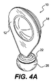
システム10の幾つかの実施形態において、アプリケータ・デバイス14は、使用準備のできた形態で提供されてもよい。例えば、図2Bに示すように(図4Aも参照)、アプリケータ・デバイス14は、アプリケータ・パッド26がベース22に取り付けられ、且つパケット12が蓋28によってレセプタクル18内に包囲された状態で、貯蔵され、パッケージされ、及び/又は輸送などをされてもよい。こうした実施形態において、パケット12は、例えば消毒流体のような流体が予め充填されてもよい。
In some embodiments of the
レセプタクル
レセプタクル18は、パケット12を受け入れ、且つパケット12からの流体の排出を容易にするように構成されてもよい。図2B及び図2Dに示すように、ハンドル16は、レセプタクル18とベース22との間の滑らかでテーパ状のネック部56のような、吸収体パッド26への流体の送達を容易にする機構を有してもよく、ベース22は遠位開口部57を含んでもよく、該遠位開口部57を通って流体がレセプタクル18からアプリケータ・パッド26に流れてもよい。レセプタクル18は、凹部60を画定し且つリム62を有するボウル状シェル58を備えてもよい(図1参照)。蓋28は、例えば、ヒートシール、無線周波数(RF)溶着、接着剤結合、レーザ溶着、又は任意の他の適切なタイプの据付けを用いて、リム62に密封的に取り付けられてもよい。幾つかの実施形態において、レセプタクル18は、超音波溶着のためのエネルギー・ディレクタ又はテクスチャ加工された表面、或いは他の方法で蓋28をレセプタクル18に接合するものを含んでもよい。
前述の非対称の形状のようなパケット配向機構に加えて、レセプタクル18は、パケット12を受ける及び/又は固定するために、へこみ部、ウェル、リブ、エンボス、デボス、又は一連のこうした要素のような1つ又は複数の他のパケット配向機構を含んでもよいが、これに限らない。例えば、図2B及び図2Dに示すように、レセプタクル18は、パケット12と嵌合し且つ/又はパケット12上の対応する機構を保持するように形状設定されてもよい種々の段差及び/又は輪郭を含んでもよい(図1も参照)。
In addition to the packet orientation mechanism, such as the asymmetric shape described above, the
図3A〜3Cは、例示的なパケット配向機構を含んでいるアプリケータ・デバイス14の実施形態を例証する。例えば、図3Aに示すように、レセプタクル18は、1つ又は複数の内側リブ63、エンボス加工されたリッジ64、及びウェル65を形成するデボス加工領域を含ことができる。図3Bに示すように、蓋28は、図3Aに示されたレセプタクルと共に用いられるように構成されてもよい。幾つかの実施形態において、蓋28は、図3Bに示すように、蓋28の蓋ドーム67がより低い外形を有することを可能にすることができるくぼんだ面66を含むことができる。図3Cは、図3A及び図3Bに示された構成部品を含んでいる組み立てられたアプリケータ・デバイス14の断面図である。
3A-3C illustrate an embodiment of
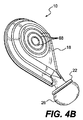
配向機構に加えて、ハンドル16はまた、ユーザによるアプリケータ・デバイス14の操作を容易にするために、1つ又は複数の外部グリップ機構を含んでもよい。例えば、レセプタクル18は、レセプタクル18のしっかりとしたグリップを促進するために、人間工学的な形状設定及び/又はサイズ設定、並びに、くぼみ、突出するグリップ部材、テクスチャ加工されたストリップ及び/又は領域、ゴム引き材料などのようなグリップ機構を含んでもよい。幾つかの実施形態において、ハンドル16は、図4Bに示すように、1つ又は複数のグリップ・リブ68を(例えば、レセプタクル18上に)含んでもよい。
In addition to the orientation mechanism, the
幾つかの実施形態において、アプリケータ・デバイス14は、レセプタクル18の中に空気が流れ込む又は外に空気が流れ出ることを可能にするように構成された通気機構を含んでもよい。こうした通気機構は、吸収体パッドへの制御された流体送達を依然として可能にしながら、流体が望ましくない場所でハンドル16から漏れ出るのを制限するように構成されてもよい。例えば、幾つかの実施形態において、通気機構は、ハンドル16の近位端20に位置してもよく、流体がハンドル16の遠位端に残留する間、及びアプリケータ・デバイス14が直立状態に保たれる間、空気はハンドル16の中に入り、且つ外に出ることができる。幾つかの実施形態において、通気機構は、蓋28とレセプタクル18のリム62との間の接合部において密封されないままにされる領域を含むことができる。例えば、或る実施形態において、レセプタクル18のリム62は、その上で蓋28が密封されないままにされてもよい溝(図示せず)を含むことができる。
In some embodiments, the
幾つかの実施形態において、アプリケータ・デバイス14の1つ又は複数の部分/構成部品は、透明又は半透明の材料で形成されてもよい。例えば、レセプタクル18の1つ又は複数の部分は、透明又は半透明の材料で形成されてもよい。幾つかの実施形態において、蓋28、パケット12、及び/又はベース22の1つ又は複数の部分は、透明又は半透明の材料で形成されてもよい。アプリケータ・デバイス14の或る部分/構成部品の透明性及び/又は半透明性は、パケット12の中に残っている流体の量の観測を可能にする場合があり、及び/又は、分与されている間のアプリケータ・デバイス14を通る流体の流れの監視を容易にする場合がある。
In some embodiments, one or more portions / components of
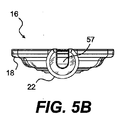
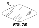
図5A及び図5Bに示すように、幾つかの実施形態において、レセプタクル18は、流体の流れをベース22の遠位開口部57に向けるように構成された三側面チャネル69を含んでもよく、ベース22には、チャネル69を組み入れるためにスロットが形成されてもよい。また、図6A及び図6Bに示すように、ハンドル16は、広がった遠位開口部57を備えた、より広いベース22を有することができる。こうしたより広いベース22は、より広いアプリケータ・パッド26と適合する場合がある。例えば、図7A及び図7Bに示すように、アプリケータ・デバイス14は、より広いベース22と、対応するより広いアプリケータ・パッド26とを含んでもよい。チャネル69、フレア型の遠位開口部57、及びより広いベース22のような機構は、アプリケータ・パッド26への流体の流れ及び/又は分散の増加を容易にすることができる。
As shown in FIGS. 5A and 5B, in some embodiments, the
ハンドル16、すなわち、レセプタクル18とベース22は、射出成形、機械加工のような任意の適切なプロセス及び/又は任意の他の適切な製造方法を用いて形成されてもよい。オープンチャネル69及び/又はフレア型の遠位開口部57のような機構は、ハンドル16の成形を容易にする場合がある。ハンドル16は、例えば、ポリエステル、S−Bブロックコポリマー、ポリオレフィンなどのような熱可塑性材料を含んでいる任意の適切な材料で形成されてもよい。
The
蓋
蓋28は、パケット12をレセプタクル18内に密封状態で包囲するように構成されてもよい。蓋28はまた、可撓性であってもよく、したがって、外部圧力の印加に応答して歪み、レセプタクル18内に配置されたときにパケット12に外部圧力を印加し、これによりパケット12を圧縮し、パケット12から流体を解放することを可能にするように構成される。幾つかの実施形態において、蓋28は、蓋28にかかる力を分散させるように構成されてもよい。例えば、幾つかの実施形態において、蓋28は、蓋ドーム67によって例証されるようにドーム形状を有してもよい(図1、図2B、及び図3B参照)。
蓋28の半硬質の実施形態では、蓋28は、熱成形すること及び打抜き加工することを含む任意の適切な方法によって形成されてもよい。蓋28が伸長可能な材料であってもよい実施形態では、蓋28は、打抜き伸長加工(die cut stretched)されてもよい。蓋28がそれから形成されてもよい例示的な材料は、レセプタクル18に密封するのに適した任意の材料を含む。こうした材料は、例えば、ポリエステル、ポリオレフィン、S−Bブロックコポリマーなどを含んでもよい。
In the semi-rigid embodiment of the
蓋28は、任意の適切な方法を用いてレセプタクル18に密封状態で取り付けられてもよい。例えば、蓋28は、ヒートシール、接着剤/糊、レーザ溶着、超音波溶着などを用いてレセプタクル18に取り付けられてもよい。
The
ベース
ベース22は、ハンドル16の遠位端24に位置してもよく、且つパケット12から解放された流体の流れをアプリケータ・パッド26に向けるように構成されてもよい。図2Bに示すように、遠位開口部57は、流体がパケット12から解放された後でアプリケータ・パッド26に流れることを可能にすることができる場合がある。以下でより詳細に説明されるように、幾つかの実施形態において、遠位開口部57は、アプリケータ・パッド26の一部を受け入れるように構成されてもよい。
Base The
ベース22は、種々の形状及びサイズに形成されてもよい。幾つかの実施形態において、図6A及び図6Bに示すように、ベース22の形状及び/又はサイズは、アプリケータ・パッド26の形状及び/又はサイズと概して対応してもよい(図1も参照)。他の実施形態において、アプリケータ・パッド26は、ベース22の形状及び/又はサイズとは異なる形状及び/又はサイズを有してもよい。
The base 22 may be formed in various shapes and sizes. In some embodiments, as shown in FIGS. 6A and 6B, the shape and / or size of the base 22 may generally correspond to the shape and / or size of the applicator pad 26 (see also FIG. 1). ). In other embodiments, the
ベース22は、レセプタクル18に対して或る角度に配向されてもよい。例えば、レセプタクル18の或る実施形態、例えば、図1のように実質的に円形の形状を有する実施形態は、例えば、レセプタクル18の実質的に円形の形状を通るレセプタクル中心軸70を中心として形成されてもよい。レセプタクル中心軸70は、ベース22を含んでいる平面74(図2B参照)と垂直な軸72に対して或る角度71に配向されてもよい。幾つかの実施形態において、角度71は、例えば図1及び図2Bに示すように、ほぼ90度であってもよい。他の実施形態において、角度71は、0から180度までの範囲内の任意の角度であってもよい。例えば、図8において、角度71は、ほぼ45度で示されている。
The base 22 may be oriented at an angle with respect to the
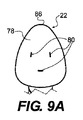
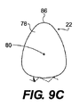
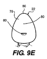
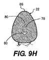
図8に示すように、ベース22は、アプリケータ・パッド26がそれに付着されるように構成されてもよい内面76及び外面78を含んでもよい。幾つかの実施形態において、図9A〜図9Hに示すように、ベース22は、アプリケータ・パッド26がその上で付着されるように構成されてもよい1つ又は複数の穿孔80を含んでもよい。穿孔80は、レセプタクル18からアプリケータ・パッド26に流体が流れることを可能にする場合がある。
As shown in FIG. 8, the
幾つかの実施形態において、図9Gに示すように、外面78は、1つ又は複数のチャネル82を含んでもよい。チャネル82は、アプリケータ・パッド26の異なる部分に流体を分散させるように構成されてもよい。また、幾つかの実施形態において、ベース22の外面78は、図9Hに示すようにテクスチャ加工されてもよい。テクスチャは、ベース22へのアプリケータ・パッド26の取付けを促進することができるだけでなく、アプリケータ・パッド26の異なる部分への流体の分散も容易にすることができる。
In some embodiments, the
或る実施形態によれば、ベース22は、レセプタクル18と結合してもよい。ベース22は、ヒンジ、接着剤、機械的相互係合、ねじ部、プレスばめ、摩擦ばめ、締まりばめ、すべりばめ、及び/又はそれらの組合せによる取り付けを含むがこれに限定されない機械分野では公知の種々の方法でレセプタクル18と結合してもよい。他の実施形態によれば、ベース22は、レセプタクル18と一体に形成されてもよい。一体のベース/ハンドルの組合せは、成形、射出成形、鋳造、機械加工、又はその組合せを含むがこれに限定されない当該技術分野では公知の種々のプロセスによって製造されてもよい。
According to some embodiments, the
或る実施形態において、アプリケータ・デバイス10は、レセプタクル18とベース22との間の交換可能な取付具を含むことができる。交換可能な取付具は、例えば、同じレセプタクル18に対する種々の形状及びサイズを有するベースの使用を容易にする場合があり、逆もまた同様である。これは、例えば、同じレセプタクル18との異なるサイズにされたアプリケータ・パッドの使用を容易にする場合がある。
In certain embodiments, the
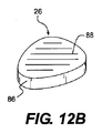
アプリケータ・パッド
アプリケータ・パッド26は、レセプタクル18の内側部分と流体連通する状態でベース22と結合されるように構成されてもよい。幾つかの実施形態において、図2Bに示すように、アプリケータ・パッド26の一部は、ベース22の遠位開口部57の中に挿入され、且つ遠位開口部57の外側部分84の周りに巻きつけられてもよい。アプリケータ・パッド26は、遠位開口部57の外側部分84上で(例えば、超音波溶着、接着剤などを介して)ベース22に取り付けられてもよい。アプリケータ・パッド26が周りに巻きつけられる幾つかの実施形態において(例えば、図2Bに示すように)、アプリケータ・パッド26は、例えば、図1に示されたような形状に少なくとも部分的に予め形成されてもよい。例えば、アプリケータ・パッド26は、成形され、切断され、又は形状設定され、且つ/又はこうした構成へと圧縮されてもよい。
Applicator
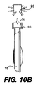
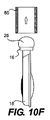
アプリケータ・パッド26が周りに巻きつけられる幾つかの実施形態は、ディスク型のパッドから、ディスクの一部をベース22の遠位開口部57の中に挿入し、次いで、遠位開口部57の外側部分84の周りにディスクの別の部分を巻きつけることによって形成されてもよい。図10A〜図10Fは、吸収体パッド材料の平坦なディスクから丸みをつけられたアプリケータ・パッドを作製するための一連のステップを示す。図10Aは、アプリケータ・パッド26を平坦なディスクとしてアプリケータ・デバイス14の上の位置に示す。図10Bに示すように、ディスク形状のアプリケータ・パッド26は、ベース16の遠位開口部57の中に圧縮され且つ押し込まれてもよい。図10Cは、遠位開口部57において拘束されていないディスクを示す。図10Dに示すように、ツール85が、ディスクの上にかぶさるように下方に動かされてもよい。図10Eは、アプリケータ・パッド26が遠位開口部57の外側部分84の周りに押しつけられている状態を示し、アプリケータ・パッド26は、ベース16に付着されてもよい。図10Fは、ツール85が引き上げられ、仕上がった、丸みをつけられたアプリケータ・パッド26が残されている状態を示す。
Some embodiments in which the
上で述べたように、ベース22のように、アプリケータ・パッド26は、任意の適切な形状及び/又はサイズを有してもよい。或る実施形態において、アプリケータ・パッド26は、例えば図1及び図2Bに示すように、丸みをつけられた形状、若しくは実質的に球形の又は半球形の形状を有してもよい。幾つかの実施形態において、アプリケータ・パッド26は、図7A及び図7B、並びに、図8、図9A〜図9H、及び図12A〜図12Dに示すように代替的な形状を有してもよい。或る実施形態において、ベース22及び/又はアプリケータ・パッド26は、図9A〜図9H及び12A〜図12Dに示すように、丸みをつけられた縁部を備えた概して三角形であってもよい。この概して三角形の形状は、図示されるように涙の滴形状に近似していてもよい。ベース22の他の例示的な形状は、長方形、円形、楕円形、ダイヤモンド、種々の多角形の形状(例えば、図7A及び図7B参照)、及び/又はその組み合わせを備えている複雑な形状を限定ではなく含んでいてもよい。
As mentioned above, like
概して三角形/涙の滴の形状又はダイヤモンド形状は、アプリケータ・デバイス14が種々の輪郭を有する表面上で用いられることを可能にすることができる場合がある。例えば、三角形、又は、例えばダイヤモンド形状(例えば図7A及び図7B参照)の角部における、より小さい先端部、特に最遠位先端部86は、間隙及びより小さい表面形状部へのアクセスを可能にする場合があり、一方、アプリケータ・パッド26の広い近位端は、より大きい、より緩やかな輪郭の表面に流体を塗布することを可能にする、大きいパッド表面を提供する場合がある。
In general, the triangular / teardrop shape or diamond shape may allow the
アプリケータ・パッド26は、種々の取付機構のいずれかを用いてベース22と結合してもよい。例えば、アプリケータ・パッド26は、例えば、医療等級のシアノアクリレート、UV硬化接着剤などを用いる接着剤結合を含んでいる任意の適切な方法を用いて、ベース22に取り付けられてもよい。幾つかの実施形態において、アプリケータ・パッド26は、RF溶着、ヒートステーキング、超音波溶着、レーザ溶着、機械的相互係合、ホック&ループ機構(例えば、Velcro(登録商標))、ねじ付部品など、並びに、これらの機構の組合せ、を用いてベース22に取り付けられてもよい。したがって、ベース22とアプリケータ・パッド26は、これらの機構のいずれかを用いて互いに取り付けられるように構成されてもよく、したがって、こうした取り付けを可能にするために適切な機構(例えば、テクスチャ、接着剤、機械的ラッチ/クランプ要素、コーティングなど)を含んでもよい。
幾つかの実施形態において、アプリケータ・パッド22は、図11に示すように、縁部溶着87を用いてベース22に取り付けられてもよい。縁部溶着87は、ハンドル16をベース22が上向きになるように治具に保持し、ベース22の上面上にアプリケータ・パッド26を位置付け、アプリケータ・パッド26とベース22との両方にわたるように超音波ホーンを降ろすことによってもたらされてもよい。このようにして、アプリケータ・パッド26は、ベース22の周りに実質的に一様に巻きつけられてもよい。このプロセスの間、超音波エネルギーが、アプリケータ・パッド26の表面をベース22の縁部に溶着し、超音波ホーンが撤収されたとき、発泡体の本体が圧縮されていない状態に膨らんで戻る。
In some embodiments, the
幾つかの実施形態において、アプリケータ・パッド26は、実質的に疎水性の発泡体を含んでもよい。代替的に又はそれに加えて、アプリケータ・パッド26は、実質的に親水性の発泡体を含んでもよい。本明細書で用いられる場合の「実質的に疎水性の発泡体」という用語は、多量の水を吸収しないポリマーベースの発泡体のことを指す。対照的に、実質的に親水性の発泡体の定義は、以下で与えられる。本開示の目的のために、実質的に疎水性の発泡体は、以下で定義されるように、実質的に親水性ではないあらゆる発泡体のことを指す。
In some embodiments, the
本明細書で用いられる場合の「実質的に親水性の発泡体」という用語は、水への親和性を有するポリマーに基づく発泡体のことを指す。例えば、本発明の或る実施形態は、オープンセルの細孔構造をもつポリウレタン発泡体を使用することができる。或る事例において、実質的に親水性の発泡体は、例えば、発泡体の重量のおよそ20倍の吸収のような高い割合の流体吸収のために設計することができる。理論に拘束されることを望むわけではないが、実質的に親水性の発泡体は、水又は活性プロトン及び/又はヒドロキシル基を含有する液体と水素結合を形成することができるポリマー鎖中の極性基の存在、毛管力によって発泡体構造の本体の中に液体を通す微細なオープンセル細孔構造、並びに/又は発泡体マトリクスへの超吸収体のような吸収体材料及び/若しくは界面活性剤の添加を含むがこれに限定されない1つ又は複数の機構を通じて水への親和性を実証することができる。本発明の或る実施形態において用いることができる実質的に親水性の発泡体は、Foamex International,Inc.(米国ペンシルバニア州メディア)、Crest Foam Industries,Inc.(米国ニュージャージー州ムーナチー)、Rynel,Inc.(米国メーン州ブースベイ)、Avitar,Inc.(米国マサチューセッツ州キャントン)、Lendell Manufacturing,Inc.(米国ミシガン州チャールズ)、及びCopura(デンマーク)を含む組織から入手可能である。加えて、Hermannらの米国特許第5,135,472号を含む、或る特許は、本発明の或る実施形態において用いられてもよい実質的に親水性の発泡体を開示する。幾つかの実施形態において、アプリケータ・パッド26は、Foamex疎水性網目状ポリウレタン発泡体で形成されてもよい。
The term “substantially hydrophilic foam” as used herein refers to a foam based on a polymer having an affinity for water. For example, certain embodiments of the present invention may use polyurethane foam with an open cell pore structure. In some cases, a substantially hydrophilic foam can be designed for a high percentage of fluid absorption, such as absorption approximately 20 times the weight of the foam. While not wishing to be bound by theory, substantially hydrophilic foams are polar in the polymer chain that can form hydrogen bonds with water or liquids containing active protons and / or hydroxyl groups. The presence of groups, fine open-cell pore structures that allow liquids to pass through the body of the foam structure by capillary forces, and / or of absorbent materials and / or surfactants such as superabsorbents in the foam matrix Affinity to water can be demonstrated through one or more mechanisms including but not limited to addition. Substantially hydrophilic foams that can be used in certain embodiments of the present invention are described in Foamex International, Inc. (Media, Pennsylvania, USA), Crest Foam Industries, Inc. (Moonachee, NJ, USA), Rynel, Inc. (Booth Bay, Maine, USA), Avital, Inc. (Canton, Massachusetts, USA), Lendell Manufacturing, Inc. (Charles, Michigan, USA), and from organizations including Copura (Denmark). In addition, certain patents, including Hermann et al. US Pat. No. 5,135,472, disclose substantially hydrophilic foams that may be used in certain embodiments of the present invention. In some embodiments, the
アプリケータ・パッド26は、フェルト地を含んでもよく、又はフェルト加工されていないものでもよい。加えて、アプリケータ・パッド26は、網状組織を含んでもよく、又は網状化されていないものでもよい。幾つかの実施形態において、アプリケータ・パッド26は、多数のパッド材料を含んでもよい。こうした実施形態において、上記の特徴の任意の組合せが採用されてもよい。例えば、1つの例示的な多材料パッドにおいて、1つのパッド材料は疎水性であってもよく、第2のパッド材料は親水性であってもよい。
The
アプリケータ・パッド26は、単一の層又は多数の層を含んでもよい。加えて、幾つかの実施形態において、アプリケータ・パッド26は、アプリケータ・パッド26を通る流体の分散及び/又は流れを促進するためにスリットを含んでもよい。図12A〜図12Dは、上記に挙げられた機構の種々の組合せを有するアプリケータ・パッド26の幾つかの例示的な実施形態を例証する。例えば、幾つかの実施形態において、アプリケータ・パッド26は、図12Aに示すように、スリットのない単一の層を備えてもよい。種々の実施形態において、アプリケータ・パッド26は、図12Bに示すように、スリット88を含んでいてもよい単一の層を備えてもよい。図12Bに例証されるように、アプリケータ・パッド26は、多数のスリットを含んでもよい。さらに、スリット88は、パターンで提供されてもよい。例えば、図12Bは、或る角度に配向された実質的に平行なスリット88のパターンを示す。
他の実施形態において、アプリケータ・パッド26は、多数の層を含んでもよい。図12C及び図12Dに示すように、アプリケータ・パッド26は、ベース層90とラミネート層92とを備えてもよい。ベース層90に及び/又はラミネート層92にスリット88が提供されてもよい。図12C及び図12Dは、スリット88が少なくともラミネート層90に提供された実施形態を例証する。図12Cは、図12Bに示されたものと同様の実質的に平行なスリット88のパターンを示す。図12Cは、或る角度に配向された図12Bのものとは対照的に、スリット88が概して横方向に配向されたパターンを例証する。スリット88は、任意の角度で配置されてもよい。加えて、スリット88は、概して円形の図12Dのスリット88のような多数の形状のいずれかに提供されてもよい。スリット88はまた、楕円形、多角形などを含むがこれに限定されない他の種々の形状に形成されてもよい。スリット88は、任意の適切な様式、例えば、ダイ・カッティング/キス・カッティングによって形成されてもよい。
In other embodiments,
幾つかの実施形態において、各層は、異なるパッド材料で形成されてもよい。種々の実施形態において、アプリケータ・パッド26は、少なくとも1つの擦過層を含んでもよい。或る用途において、擦過層は、処置の対象となる領域、例えば表皮を擦過するために用いられてもよい。擦過は、流体の分与前、分与の間、及び/又は分与後に行われてもよい。或る実施形態において、擦過は、対象となる領域の処置を促進するために、或る生体材料、例えば、身体の脂、身体の汚れ、及び/又は細菌を取れやすくすることができる。例えば、消毒液の塗布の前に、ユーザは消毒薬塗布プロセスの有効性を改善するために細菌を取れやすくするために患者の表皮を擦過してもよい。或る実施形態において、擦過層は、領域を清浄にするためにより多い量の擦過及び/又はより激しい擦過を容易にすることができる、1つよりも多い材料層を備えてもよい。
In some embodiments, each layer may be formed of a different pad material. In various embodiments, the
或る実施形態において、擦過層は、種々のテクスチャ及び/又は織りの、例えば、ガーゼ状又は発泡体の材料を備えてもよい。或る実施形態において、例示的なガーゼ状材料は、綿、レーヨン、ナイロン、及び/又はそれらの組合せを含むがこれに限定されない、擦過を容易にする種々の材料から作製されてもよい。擦過層材料は、様々な摩損度を呈する多数の材料から選択されてもよい。発泡体材料については、摩損レベルは、数ある中でも、セル/孔のサイズに応じて異なることがある。早生児の皮膚は、薄くて傷つきやすい可能性があり、したがって、ナイロン又はレーヨンから作製された擦過層を備えるアプリケータ・デバイスは、綿から作製された擦過層よりも好ましい場合がある。或る実施形態において、擦過層は、異なる材料の複数の層を備えてもよい。幾つかの実施形態、例えば発泡体擦過層において、擦過層は、ベース22に及び/又はアプリケータ・パッド24にフレームラミネートしてもよい。
In certain embodiments, the abrading layer may comprise various textures and / or weaves, such as gauze or foam materials. In certain embodiments, exemplary gauze-like materials may be made from a variety of materials that facilitate rubbing, including but not limited to cotton, rayon, nylon, and / or combinations thereof. The abrading layer material may be selected from a number of materials that exhibit varying friability. For foam materials, the level of wear can vary depending on the cell / pore size, among other things. The skin of premature infants can be thin and vulnerable, so an applicator device with a scratch layer made from nylon or rayon may be preferred over a scratch layer made from cotton. In certain embodiments, the scratch layer may comprise multiple layers of different materials. In some embodiments, such as a foam rubbed layer, the rubbed layer may be frame laminated to the
図12C及び図12Dに例証されるように、ラミネート層92(擦過層を備えてもよい)は、アプリケータ・パッド26のベース層90の形状に概して対応する形状を有してもよい。しかしながら、或る実施形態において、ラミネート層92は、円形、楕円形、長方形、三角形、多角形など、或いはこのうちの1つ又は複数を含んでいる複雑な形状を含むがこれに限定されない種々の他の形状を有してもよい。アプリケータ・パッド26の層は、接着剤結合(例えば、感圧接着剤を用いる)、融着、フレームラミネート、ヒートステーキング、超音波溶着などを含むがこれに限定されない種々の取付機構によって互いに取り付けられてもよい。発泡体のようなアプリケータ・パッド材料に種々の材料をラミネートする及び/又は取り付けるための方法は、当該技術分野では公知である。例えば、米国特許出願第10/829,919号、米国特許仮出願第60/464,306号、及びPCT整理番号第US04/012474号のすべては、材料をポリウレタン発泡体に取り付けるための方法及び装置を開示している。
As illustrated in FIGS. 12C and 12D, the laminate layer 92 (which may include a scratch layer) may have a shape that generally corresponds to the shape of the
アプリケータ・デバイス14及び/又はパケット12を含むアプリケータ・システム10の構成部品は、エチレンオキシド(「(Et)2O」)、ガンマ放射線、電子ビーム、及び又は蒸気への露出を含むがこれに限定されない当該技術分野では公知の種々の方法で滅菌されるように構成されてもよい。種々の実施形態によれば、流体はまた、濾過、ガンマ放射線、電子ビーム、及び又は蒸気への露出を含むがこれに限定されない当該技術分野では公知の種々の方法で滅菌されてもよい。例えば、米国特許第6,682,695号は、本発明の或る実施形態と一致し得る流体を滅菌するための方法を開示する。
The components of
本発明の種々の他の実施形態は、ここに開示される本発明の明細書及び実施の考察から当業者には明らかとなるであろう。明細書及び例は、単なる例示として考えられることを意図されており、本発明の真の範囲及び精神は以下の請求項によって示されている。 Various other embodiments of the present invention will be apparent to those skilled in the art from consideration of the specification and practice of the invention disclosed herein. It is intended that the specification and examples be considered as exemplary only, with a true scope and spirit of the invention being indicated by the following claims.
Claims (50)
近位端及び遠位端を有するハンドルであって、
流体を収容するパケットを受け入れ、且つ前記パケットからの前記流体の排出を容易にするように構成された、前記ハンドルの前記近位端におけるレセプタクル、および
前記パケットを前記レセプタクル内に密封的に包囲するように構成され、且つ外部圧力の印加に応答して歪み、前記レセプタクル内に配置されたときに前記パケットに前記外部圧力を印加してそれにより前記パケットを圧縮し、前記パケットから前記流体を解放することを可能にするように構成された可撓性の蓋であって、前記蓋が、前記蓋に印加された力を分散させるように構成される、蓋、を備えるハンドルと、
前記解放された流体の流れを向けるように構成され、遠位開口部を含んでいる、前記ハンドルの遠位端におけるベースと、
前記レセプタクルの内側部分と流体連通する状態で前記ベースと結合されたアプリケータ・パッドであって、前記パッドの一部が前記ベースの前記遠位開口部内に挿入され、前記パッドの一部が前記ベースの前記遠位開口部の外側部分に巻きつけられた、アプリケータ・パッドと、
を備えるアプリケータ・デバイス。 An applicator device for applying a fluid, comprising:
A handle having a proximal end and a distal end,
A receptacle at the proximal end of the handle configured to receive a packet containing fluid and facilitate drainage of the fluid from the packet; and sealingly enclose the packet within the receptacle Configured to be distorted in response to application of external pressure, applying the external pressure to the packet when placed in the receptacle, thereby compressing the packet and releasing the fluid from the packet A handle comprising a flexible lid configured to allow the lid to be configured to disperse a force applied to the lid ;
A base at the distal end of the handle configured to direct the released fluid flow and including a distal opening;
An applicator pad coupled to the base in fluid communication with an inner portion of the receptacle, wherein a portion of the pad is inserted into the distal opening of the base, and a portion of the pad is An applicator pad wrapped around the outer portion of the distal opening of the base;
An applicator device comprising:
近位端及び遠位端を有するハンドルであって、
流体を収容するパケットを受け入れ、且つ前記パケットからの前記流体の排出を容易にするように構成された、前記ハンドルの前記近位端におけるレセプタクルであって、前記アプリケータ・デバイスが、前記レセプタクルの中に空気が流れ込む、又は外に空気が流れ出ることを可能にするように構成された少なくとも1つの通気機構を含む、レセプタクル、および
前記パケットを前記レセプタクル内に密封的に包囲するように構成され、且つ外部圧力の印加に応答して歪み、前記レセプタクル内に配置されたときに前記パケットに前記外部圧力を印加してこれにより前記パケットを圧縮し、前記パケットから前記流体を解放することを可能にするように構成された可撓性の蓋であって、前記通気機構が、前記蓋と前記レセプタクルとの間の接合部において密封されないままにされる領域を備える、蓋、を備えるハンドルと、
前記解放された流体の流れを向けるように構成され、遠位開口部を含んでいる、前記ハンドルの前記遠位端におけるベースと、
前記ベースの前記遠位開口部を介して前記レセプタクルの内側部分と流体連通する状態で前記ベースと結合されるように構成されたアプリケータ・パッドと、
を備えるアプリケータ・デバイス。 An applicator device for applying a fluid, comprising:
A handle having a proximal end and a distal end,
A receptacle at the proximal end of the handle configured to receive a packet containing fluid and facilitate drainage of the fluid from the packet, wherein the applicator device includes a receptacle of the receptacle; A receptacle, including at least one venting mechanism configured to allow air to flow in or out of the air, and to sealingly enclose the packet in the receptacle; And distorted in response to the application of external pressure, allowing the external pressure to be applied to the packet when placed in the receptacle, thereby compressing the packet and releasing the fluid from the packet A flexible lid configured to allow the ventilation mechanism to be disposed between the lid and the receptacle. A handle comprising a lid with an area left unsealed at the joint ;
A base at the distal end of the handle configured to direct the released fluid flow and including a distal opening;
An applicator pad configured to be coupled to the base in fluid communication with an inner portion of the receptacle via the distal opening of the base;
An applicator device comprising:
流体を収容するパケットであって、
それらの間に前記流体を収容する密封された空間を画定する第1及び第2の対向するパケット側部と、
前記パケットから前記流体を解放するために前記パケットが圧縮されると破壊するように構成された破壊可能領域と、
以前は密封されていた前記空間が実質的に完全につぶされるように、前記パケットが圧縮されると前記パケットの前記第1パケット側部が凸形位置から凹形位置に反転することを可能にする崩壊可能機構と、
を備えるパケットと、
アプリケータ・デバイスであって、
近位端及び遠位端を有するハンドルであって、前記ハンドルの前記近位端にレセプタクルを備え、前記レセプタクルが、前記流体の前記パケットを受け入れ且つ前記パケットからの前記流体の排出を容易にするように構成された、ハンドルと、
前記ハンドルの前記遠位端に配置され、前記解放された流体の流れを向けるように構成され、遠位開口部を含んでいる、ベースと、
前記ベースの前記遠位開口部を介して前記レセプタクルの内側部分と流体連通する状態で前記ベースと結合されるように構成されたアプリケータ・パッドと、
を備えるアプリケータ・デバイスと、
を備え、
前記レセプタクルと前記パケットが、前記パケットを前記レセプタクルに対して配向する、対応する配向機構を有する、システム。 A system for applying a fluid, the system comprising:
A packet containing a fluid,
First and second opposing packet sides defining a sealed space containing the fluid therebetween,
A destructible region configured to destroy when the packet is compressed to release the fluid from the packet;
Allows the first packet side of the packet to flip from a convex position to a concave position when the packet is compressed so that the previously sealed space is substantially completely collapsed A collapsible mechanism to
A packet comprising:
An applicator device,
A handle having a proximal end and a distal end, the receptacle comprising a receptacle at the proximal end of the handle, the receptacle receiving the packet of fluid and facilitating drainage of the fluid from the packet Configured with a handle,
A base disposed at the distal end of the handle, configured to direct the released fluid flow, and including a distal opening;
An applicator pad configured to be coupled to the base in fluid communication with an inner portion of the receptacle via the distal opening of the base;
An applicator device comprising:
Equipped with a,
The system wherein the receptacle and the packet have a corresponding orientation mechanism that orients the packet relative to the receptacle .
前記パケットの前記第1パケット側部及び前記第2パケット側部が、前記第1周辺部と前記第2周辺部との間の接合部において互いに密封され、
前記第1中央部が前記第2周辺部よりも小さい直径を有し、それにより、前記崩壊可能機構を形成する、請求項31に記載のシステム。 The first packet side portion includes a first central portion and a first peripheral portion, and the second packet side portion includes a second central portion and a second peripheral portion;
The first packet side and the second packet side of the packet are sealed to each other at a junction between the first peripheral portion and the second peripheral portion;
32. The system of claim 31 , wherein the first central portion has a smaller diameter than the second peripheral portion, thereby forming the collapsible mechanism.
Applications Claiming Priority (3)
| Application Number | Priority Date | Filing Date | Title |
|---|---|---|---|
| US14154008P | 2008-12-30 | 2008-12-30 | |
| US61/141,540 | 2008-12-30 | ||
| PCT/US2009/069730 WO2010078361A1 (en) | 2008-12-30 | 2009-12-29 | Fluid application device and method |
Publications (2)
| Publication Number | Publication Date |
|---|---|
| JP2012513879A JP2012513879A (en) | 2012-06-21 |
| JP5773528B2 true JP5773528B2 (en) | 2015-09-02 |
Family
ID=41786415
Family Applications (1)
| Application Number | Title | Priority Date | Filing Date |
|---|---|---|---|
| JP2011544595A Expired - Fee Related JP5773528B2 (en) | 2008-12-30 | 2009-12-29 | Fluid application device and method |
Country Status (18)
| Country | Link |
|---|---|
| US (2) | US8858484B2 (en) |
| EP (3) | EP2376176B1 (en) |
| JP (1) | JP5773528B2 (en) |
| KR (1) | KR101605222B1 (en) |
| CN (1) | CN102333564B (en) |
| AR (1) | AR074930A1 (en) |
| AU (1) | AU2009335040B2 (en) |
| BR (1) | BRPI0923606A2 (en) |
| CA (1) | CA2748488C (en) |
| DK (1) | DK2376176T3 (en) |
| ES (2) | ES2605257T3 (en) |
| MX (1) | MX2011006967A (en) |
| MY (1) | MY163790A (en) |
| PT (1) | PT2376176E (en) |
| RU (1) | RU2535767C2 (en) |
| SG (1) | SG172423A1 (en) |
| TW (1) | TWI556845B (en) |
| WO (1) | WO2010078361A1 (en) |
Families Citing this family (35)
| Publication number | Priority date | Publication date | Assignee | Title |
|---|---|---|---|---|
| JP5493770B2 (en) * | 2009-11-26 | 2014-05-14 | 花王株式会社 | Squeeze container |
| JP5785755B2 (en) * | 2010-04-02 | 2015-09-30 | 花王株式会社 | Contents extrusion container |
| US9309019B2 (en) | 2010-05-21 | 2016-04-12 | Adhezion Biomedical, Llc | Low dose gamma sterilization of liquid adhesives |
| US8550737B2 (en) | 2010-09-20 | 2013-10-08 | Adhezion Biomedical, Llc | Applicators for dispensing adhesive or sealant material |
| JP5676190B2 (en) * | 2010-09-27 | 2015-02-25 | テルモ株式会社 | Liquid applicator |
| JP5624926B2 (en) * | 2011-03-30 | 2014-11-12 | 花王株式会社 | Contents extrusion container |
| US9066711B2 (en) | 2011-11-02 | 2015-06-30 | Adhezion Biomedical, Llc | Applicators for storing sterilizing, and dispensing an adhesive |
| US9138500B2 (en) | 2011-11-09 | 2015-09-22 | William Beaumont Hospital | Apparatus and method for sanitizing stethoscope heads |
| US10806814B2 (en) * | 2011-11-09 | 2020-10-20 | Mark D. Kolins | Stethoscope and hand sanitizer |
| US9867973B2 (en) * | 2013-06-17 | 2018-01-16 | Medline Industries, Inc. | Skin antiseptic applicator and methods of making and using the same |
| US10791816B2 (en) * | 2013-07-01 | 2020-10-06 | Selva Kumar | Fluid discharger and applicator device |
| US9757551B2 (en) | 2013-10-04 | 2017-09-12 | Carefusion 2200, Inc. | Antiseptic applicator |
| US9770563B1 (en) * | 2013-11-14 | 2017-09-26 | Halo Light Works, LLC | Apparatus for transferring and dispensing essential oils and waxes |
| US20150209228A1 (en) * | 2014-01-30 | 2015-07-30 | Merle Bruce | Squeezable Ampule with Breakable Seal in Nose Bleed Kit |
| SG11201609759SA (en) * | 2014-05-30 | 2016-12-29 | Amorepacific Corp | Cosmetic composition applicator including impermeable sheet |
| PL3315164T3 (en) | 2015-06-25 | 2024-03-11 | Otsuka Pharmaceutical Factory, Inc. | Applicator for medical-use liquids |
| JP6691425B2 (en) * | 2016-04-28 | 2020-04-28 | 花王株式会社 | Liquid dropping tool |
| USD890434S1 (en) * | 2016-11-10 | 2020-07-14 | Steven Tyler BROWN | Hand-held fluid-substance applicator |
| US20180126136A1 (en) * | 2016-11-10 | 2018-05-10 | Matblok Ventures Inc. | Hand-held fluid-substance applicator |
| US10596360B2 (en) | 2017-04-03 | 2020-03-24 | Simple Life Products LLC | Applicator for a topical agent and methods of use thereof |
| WO2018191218A1 (en) * | 2017-04-11 | 2018-10-18 | Ojip, Llc | Device for applying and removing nail polish |
| EP3628314B1 (en) * | 2017-04-19 | 2023-07-26 | Otsuka Pharmaceutical Factory, Inc. | Olanexidine as anti-inflammatory agent |
| JP2021532182A (en) * | 2018-07-24 | 2021-11-25 | オルソフォー,エルエルシー | Ready-to-use, finally sterile packaging and usage for surgical disinfectants |
| US12472162B2 (en) | 2018-07-24 | 2025-11-18 | Carefusion 213, Llc | Ready-to-use, terminally sterile packaging for surgical antiseptic and method of use |
| JP2021534045A (en) * | 2018-08-21 | 2021-12-09 | イリノイ トゥール ワークス インコーポレイティド | Folding seal flexible valve |
| JP6744680B1 (en) * | 2018-11-05 | 2020-08-19 | 株式会社エイエムジー | Liquid material impregnation member |
| EP3905920B1 (en) | 2019-01-03 | 2022-11-02 | The Procter & Gamble Company | Personalized skin care system |
| US11419589B1 (en) * | 2019-01-07 | 2022-08-23 | Laura McGevna Nelson | Biopsy instrument with ink-filled membrane |
| US12144949B2 (en) * | 2019-02-26 | 2024-11-19 | Solventum Intellectual Properties | System and method for prepping liquid |
| WO2021127153A1 (en) * | 2019-12-18 | 2021-06-24 | Morrow Richard P | Travel size deodorant dispenser with improved cap |
| WO2021146379A1 (en) * | 2020-01-16 | 2021-07-22 | Selva Kumar | Fluid discharger and applicator device, method for assembling and manufacturing the same and assembling system |
| US20240350781A1 (en) * | 2021-08-17 | 2024-10-24 | Becton, Dickinson And Company | Skin Disinfectant Wipe |
| US20230126287A1 (en) * | 2021-10-21 | 2023-04-27 | Gyrus Acmi, Inc. D/B/A Olympus Surgical Technologies America | Methods and systems for disinfecting surgical site |
| US12558524B2 (en) | 2022-03-18 | 2026-02-24 | Sage Products, Llc | Preoperative skin preparation applicator |
| USD1094871S1 (en) | 2022-06-21 | 2025-09-23 | Practical Science Llc | Skincare applicator |
Family Cites Families (172)
| Publication number | Priority date | Publication date | Assignee | Title |
|---|---|---|---|---|
| US359527A (en) * | 1887-03-15 | Device foe | ||
| US1715914A (en) | 1928-04-07 | 1929-06-04 | Northam Warren Corp | Manicure applicator |
| US2180248A (en) | 1937-06-07 | 1939-11-14 | Layne Curtis | Pocket antiseptic dispenser |
| US2218362A (en) | 1939-03-09 | 1940-10-15 | Du Pont | Rubberlike interpolymers of butadiene and methyl methacrylate and process for making same |
| US2218862A (en) | 1939-04-04 | 1940-10-22 | Dora W Vredenburgh | Lip rouge applicator |
| US2568328A (en) | 1948-08-06 | 1951-09-18 | Elby Joseph | Nail polish applicator |
| US2783489A (en) | 1952-08-28 | 1957-03-05 | Bogoslowsky Elisabeth | Lipstick brush applicator |
| US3080179A (en) | 1959-10-06 | 1963-03-05 | Huntsinger Associates | Slip engaging portion of drill string formed of increased wall thickness and reduced hardness |
| US3080197A (en) * | 1960-05-02 | 1963-03-05 | Deutsch Simon | Method of manufacture of a liquid applicator |
| US3152352A (en) * | 1962-09-13 | 1964-10-13 | Jr Samuel J Kosik | Dispenser for rejuvenating wiper blades |
| FR1449600A (en) * | 1964-09-14 | 1966-05-06 | Fr Des Laboratoires Labaz Soc | Improvements to flexible material bottles, especially for medicinal products |
| GB1081624A (en) | 1965-03-18 | 1967-08-31 | Chiswick Products Ltd | Improvements in or relating to applicators for liquids, pastes or other flowable substances |
| US3481876A (en) | 1966-08-12 | 1969-12-02 | Tdk Electronics Co Ltd | Manganese zinc ferrite containing calcium oxide and at least one of tantalum oxide and niobium oxide |
| US3466131A (en) * | 1967-09-07 | 1969-09-09 | Becton Dickinson Co | Dispensing applicator package |
| US3481676A (en) * | 1968-02-08 | 1969-12-02 | Gilbert Schwartzman | Disposable self-container applicator |
| US3647305A (en) | 1969-03-13 | 1972-03-07 | Mary Joan H Baker | Packet technology |
| US3613685A (en) | 1969-07-08 | 1971-10-19 | Verne J Reynolds | Surface-conforming disposable surgical preparation applicator and tray therefor |
| US3647605A (en) | 1970-01-14 | 1972-03-07 | American Tech Ind | Artificial plant utilizing a three-dimensional shell framework |
| DE2014009A1 (en) | 1970-03-24 | 1971-10-07 | Elektro Mechanik GmbH, 5961 Wen denerhutte | Automatic switching device for hydromechanical multi-speed transmissions |
| DE2017009A1 (en) * | 1970-04-09 | 1971-10-21 | Fritz, Victor, 6500 Mainz | Applicator for containers with cleaning liquids of all kinds |
| US3687140A (en) | 1971-03-17 | 1972-08-29 | Verne J Reynolds | Surface conforming disposable surgical preparation applicator |
| US3774609A (en) | 1972-01-31 | 1973-11-27 | G Schwartzman | Surgical preparatory applicator |
| US3757782A (en) | 1972-06-05 | 1973-09-11 | Vivian C Aiken | Fluid pressurizable swab applicator for medicament, antiseptic or the like |
| US3826259A (en) | 1973-06-04 | 1974-07-30 | Health Prod Inc | Self-contained disposable swab-type medication applicator |
| FR2232923A5 (en) | 1973-06-07 | 1975-01-03 | Dagada Louis | Method for producing atomizer container - uses two overlying sheets with mating depressions forming chamber |
| US3901233A (en) | 1973-11-26 | 1975-08-26 | Murray Grossan | Ear applicator |
| US3891331A (en) | 1974-06-14 | 1975-06-24 | Marion Health & Safety Inc | Unit for dispensing liquid from a frangible ampoule |
| US3929135A (en) | 1974-12-20 | 1975-12-30 | Procter & Gamble | Absorptive structure having tapered capillaries |
| USD245221S (en) | 1976-03-22 | 1977-08-02 | Earl Hoyt | Disposable applicator with liquid supply |
| US4127339A (en) | 1976-10-19 | 1978-11-28 | Malacheski Joseph J | Dispenser package for fluent material |
| US4183684A (en) | 1977-11-29 | 1980-01-15 | Marion Health & Safety, Inc. | Fluid dispensing unit |
| US4148318A (en) | 1977-12-27 | 1979-04-10 | Abbott Laboratories | Tool for surgical preparations having an internal supply of antiseptic solution |
| US4219283A (en) | 1978-04-17 | 1980-08-26 | Buckley Michael A | Container having an interiorly telescoping dispensing member |
| US4430013A (en) | 1979-07-23 | 1984-02-07 | Kaufman Jack W | Disposable swab article |
| US4291697A (en) | 1980-04-18 | 1981-09-29 | Stephen Georgevich | Cleaning and application device for medical purposes |
| US4304869A (en) * | 1980-05-27 | 1981-12-08 | American Sterilizer Company | Apparatus for rupturing a sealed, frangible container |
| EP0046021B1 (en) | 1980-08-11 | 1985-02-13 | Imperial Chemical Industries Plc | Sachets and methods for their production |
| US4519795A (en) | 1980-12-15 | 1985-05-28 | Baxter Travenol Laboratories, Inc. | Disposable swab |
| US4696393A (en) | 1981-10-19 | 1987-09-29 | Laipply Thomas C | Applicator wipe for inviscid fluids |
| US4427115A (en) | 1981-10-19 | 1984-01-24 | Laipply Thomas C | One piece alcohol preparation device |
| DE3150019A1 (en) | 1981-12-17 | 1983-06-23 | Henkel KGaA, 4000 Düsseldorf | "SPONGE APPLICATION HEAD" |
| USD288780S (en) | 1984-07-31 | 1987-03-17 | Wagner Spray Tech | Combined liquid container, applicator and scraper or similar article |
| USD292672S (en) | 1984-12-21 | 1987-11-10 | Nicholas Kiwi (Pacific) Pty. Limited | Combined container and applicator for liquid shoe polish or similar article |
| SE458986B (en) | 1985-03-29 | 1989-05-29 | Draco Ab | DOSFOERPACKNING |
| US4643725A (en) | 1985-07-01 | 1987-02-17 | Marilyn Schlesser | Combination package and applicator |
| US4648506A (en) | 1985-09-06 | 1987-03-10 | Land O'lakes, Inc. | Package with spreader for spreadable material |
| CA1284784C (en) | 1985-11-18 | 1991-06-11 | David F. Wirt | Liquid applicator |
| US4925327A (en) | 1985-11-18 | 1990-05-15 | Minnesota Mining And Manufacturing Company | Liquid applicator with metering insert |
| US4869612A (en) | 1985-12-09 | 1989-09-26 | Mooney Charles W | Liquid applicator especially suitable for application of suntan lotion |
| US4701168A (en) | 1986-04-25 | 1987-10-20 | Span America Medical Systems, Inc. | Applicator with fulcrum for bending |
| US4896768A (en) | 1986-10-06 | 1990-01-30 | Lab Products, Inc. | Anti-bacterial and anti-viral presaturated wipe product |
| US5135472A (en) | 1987-02-09 | 1992-08-04 | United Foam Plastics Corporation | Non-linting composite gauze material |
| US4963045A (en) | 1987-05-15 | 1990-10-16 | The Willcox Family Trust | Dispenser-applicator for spreading substances |
| NL8701700A (en) | 1987-07-17 | 1989-02-16 | Heijenga S Management B V | HOLDER FOR A LIQUID OR PASTIC PRODUCT. |
| US4812067A (en) | 1987-11-13 | 1989-03-14 | Brown James B | Disposable applicator package |
| DE3814305A1 (en) | 1988-04-28 | 1989-11-09 | Geka Brush Georg Karl Gmbh | APPLICATION DEVICE FOR COSMETIC AND MEDICAL APPLICATIONS |
| US4875602A (en) | 1988-06-15 | 1989-10-24 | Triad Direct Incorporated | Self-contained liquid dispensing device |
| US5098297A (en) | 1988-10-04 | 1992-03-24 | John O. Butler Company | Apparatus for application of a tooth desensitizing composition |
| US5087138A (en) | 1989-11-02 | 1992-02-11 | Rosemarie Terbrusch | Suntan oil applicator |
| CA2038251A1 (en) | 1990-03-14 | 1991-09-15 | Cedric Basil Hilton Thompson | Antiseptic composition |
| US4957385A (en) | 1990-04-26 | 1990-09-18 | Primary Delivery Systems, Inc. | Ampule solution dispenser applicator |
| US5135112A (en) | 1990-07-05 | 1992-08-04 | Melvin Kamen | Cosmetic compact case with telescopic cover and removable applicator |
| CA2064664C (en) | 1991-04-05 | 2000-01-11 | Hiroshi Ishikawa | Biguanide derivatives, manufacturing method thereof, and disinfectants containing the derivatives |
| US5181621A (en) | 1991-05-15 | 1993-01-26 | Plaehn Jay L | Tub-shower header-bar accessory-rack w/universal-bracket |
| US5215221A (en) | 1992-05-07 | 1993-06-01 | The Procter & Gamble Company | Disposable unit dose dispenser for powdered medicants |
| US5616348A (en) | 1992-09-18 | 1997-04-01 | West Agro, Inc. | Germicidal detergent-iodine compositions including polyvinyl pyrrolidone and compatible nonionic surfactant complexors |
| GB2272644B (en) | 1992-10-21 | 1997-04-02 | James Olarewaju Olagbo Oladipo | Surgical skin preparation device |
| US20010050083A1 (en) | 1992-10-28 | 2001-12-13 | Marchitto Kevin S. | Irradiation enhanced permeation and delivery |
| US5288159A (en) | 1992-12-04 | 1994-02-22 | Minnesota Mining And Manufacturing Company | Liquid applicator with frangible ampoule and support |
| USD351338S (en) | 1992-12-28 | 1994-10-11 | Painter's Products Inc. | Tube dispenser |
| US5577851A (en) | 1993-02-24 | 1996-11-26 | Painter's Products Inc. | Tube dispenser with sponge applicator |
| US5445462A (en) | 1993-08-03 | 1995-08-29 | Medi-Flex Hospital Products, Inc. | Liquid applicator |
| US6251100B1 (en) | 1993-09-24 | 2001-06-26 | Transmedica International, Inc. | Laser assisted topical anesthetic permeation |
| DE4413770A1 (en) | 1994-04-20 | 1995-10-26 | Matthias Hoffmeier | Collapsible plastics container in two curved parts |
| US5908256A (en) | 1994-10-07 | 1999-06-01 | Bernstein; Melvin | Bottle with built-in telescoping applicator head and valve therein |
| US5489280A (en) | 1994-10-31 | 1996-02-06 | Zimmer, Inc. | Surgical preparation solution applicator |
| US5597255A (en) | 1995-06-06 | 1997-01-28 | Yager; Timothy J. | Liquid container with applicator |
| US5509744A (en) | 1995-06-23 | 1996-04-23 | Frazier; Thomas G. | Liquid applicator with slide ring activator |
| FR2741600B1 (en) | 1995-11-23 | 1997-12-19 | Oreal | APPLICATION ASSEMBLY OF A FLUID OR SOLID PRODUCT |
| CN2280607Y (en) | 1996-03-13 | 1998-05-06 | 王玉生 | Tool handle with wooden-grain imitation |
| US5775826A (en) | 1996-05-29 | 1998-07-07 | Siebe North, Inc. | Safety fluid dispensing system |
| US5702404A (en) | 1996-06-03 | 1997-12-30 | Willingham; Suzan E. | Stool extractor |
| USD386849S (en) | 1996-07-23 | 1997-11-25 | Medi-Flex Hospital Products, Inc. | Liquid applicator |
| US5713843A (en) | 1996-08-13 | 1998-02-03 | Allegiance Corporation | Sponge applicator with fluid ball |
| US5791801A (en) * | 1996-08-30 | 1998-08-11 | Siebe North, Inc. | Liquid applicator |
| GB9619444D0 (en) | 1996-09-18 | 1996-10-30 | Boots Co Plc | Fluid dispensers |
| US5800825A (en) | 1996-11-08 | 1998-09-01 | Mcmullen; Alexandra | Mascara having enhanced drying capability |
| US6488665B1 (en) | 1997-04-08 | 2002-12-03 | Allegiance Corporation | Antimicrobial alcohol gel pre-operative skin-preparation delivery system |
| US5916882A (en) | 1997-04-08 | 1999-06-29 | Allegiance Corporation | Povidone iodine (PVP-I) alcohol gel antimicrobial pre-operative skin preparation |
| US6315480B1 (en) | 1997-04-10 | 2001-11-13 | Stephane Christopher Martel | Device for diffusing one or several fluid product doses, and device for applying a temporary adhesive tattoo using same |
| USD396911S (en) | 1997-06-02 | 1998-08-11 | Medi-Flex Hospital Products, Inc. | Liquid applicator body |
| US5829902A (en) | 1997-06-20 | 1998-11-03 | Fomby; Kenneth A. | Adjustable applicator brush |
| USD396126S (en) | 1997-06-26 | 1998-07-14 | Ohmart Susann G | Liquid applicator |
| JPH1176403A (en) | 1997-07-11 | 1999-03-23 | Olympus Optical Co Ltd | Surgical treatment instrument |
| BR9908534A (en) | 1998-01-30 | 2000-11-28 | Minnesota Mining And Manucturi | Kit to apply surgical preparation solution to a patient |
| US5961235A (en) | 1998-03-05 | 1999-10-05 | Kennedy; Patricia T. | Lotion applicator with handle reservoir |
| FR2776770B1 (en) * | 1998-03-31 | 2000-06-02 | Dalphina | METERING DEVICE FOR FLUID PRODUCTS |
| US6019765A (en) | 1998-05-06 | 2000-02-01 | Johnson & Johnson Professional, Inc. | Morsellized bone allograft applicator device |
| FR2778639B1 (en) * | 1998-05-18 | 2000-07-28 | Valois Sa | SAMPLE TYPE SPRAYING DEVICE |
| US6039488A (en) | 1998-06-25 | 2000-03-21 | Louisiana Bucks Unlimited, L.L.C. | Breakable ampule, swab and cap for scent material |
| USD416389S (en) | 1998-11-09 | 1999-11-16 | Frazier Thomas G | Liquid applicator with slide ring actuator |
| US6814519B2 (en) | 1998-11-09 | 2004-11-09 | The Procter & Gamble Company | Cleaning composition, pad, wipe, implement, and system and method of use thereof |
| US6155990A (en) | 1998-12-07 | 2000-12-05 | Fournier; Arthur M. | Cervical specimen self-sampling device (pap tampon) |
| US6755586B1 (en) | 1998-12-23 | 2004-06-29 | Thomas G. Frazier | Liquid applicator with slide ring activator tool |
| US6595940B1 (en) | 1998-12-23 | 2003-07-22 | Closure Medical Corporation | Applicator for dispensable liquids |
| DE19860759C2 (en) | 1998-12-23 | 2003-03-27 | Sergey Radchenko | injection bandages |
| US20010012851A1 (en) | 1999-07-29 | 2001-08-09 | Kristin M. Lundy | Nitric oxide releasing oxindole prodrugs for anagesic, anti-inflammatory and disease-modifying use |
| USD434525S (en) | 1999-07-30 | 2000-11-28 | Angeletta Joseph G | Liquid applicator |
| US6547468B2 (en) | 2001-06-22 | 2003-04-15 | The Procter & Gamble Company | Dosing reservoir |
| US7108440B1 (en) | 1999-10-08 | 2006-09-19 | The Procter & Gamble Company | Applicator for distributing a substance onto a target surface |
| US6708822B1 (en) | 1999-11-30 | 2004-03-23 | Cutispharma, Inc. | Compositions and kits for compounding pharmaceuticals |
| AU2001245571A1 (en) | 2000-04-03 | 2001-10-15 | 3M Innovative Properties Company | Surgical prep solution dispenser and method |
| US6422778B2 (en) | 2000-04-03 | 2002-07-23 | 3M Innovative Properties Company | Surgical prep solution applicator system and methods |
| US6503013B2 (en) | 2000-10-13 | 2003-01-07 | Pedinol Pharmacal Inc. | Method for applying a medicament and swab applicator for use therewith |
| US6415470B1 (en) | 2000-10-20 | 2002-07-09 | Benedict L. Ramrattan | Lotion applicator |
| US6536975B1 (en) * | 2000-11-10 | 2003-03-25 | Mediflex Hospital Products, Inc. | Liquid applicator with opposed wings |
| US6523550B2 (en) | 2000-12-08 | 2003-02-25 | Mccormick John | Application device |
| US6371675B1 (en) * | 2000-12-20 | 2002-04-16 | Becton, Dickinson And Company | Skin disinfectant applicator |
| USD448521S1 (en) | 2001-01-24 | 2001-09-25 | Joseph G. Angeletta | Liquid and lotion applicator |
| FR2820010B1 (en) | 2001-02-01 | 2003-04-04 | Oreal | DEVICE FOR PACKAGING AND APPLYING A PRODUCT |
| USD461596S1 (en) | 2001-03-21 | 2002-08-13 | Joseph G. Angeletta | Liquid and lotion applicator |
| US6682695B2 (en) | 2001-03-23 | 2004-01-27 | Clearant, Inc. | Methods for sterilizing biological materials by multiple rates |
| USD490561S1 (en) | 2001-05-16 | 2004-05-25 | Joseph G. Angeletta | Combined finger-held liquid and lotion applicator and cover |
| USD490562S1 (en) | 2001-05-16 | 2004-05-25 | Joseph G. Angeletta | Liquid and lotion applicator |
| USD536481S1 (en) | 2001-05-16 | 2007-02-06 | Angeletta Joseph G | Replaceable component for a liquid and lotion applicator |
| USD481164S1 (en) | 2001-07-02 | 2003-10-21 | Joseph G. Angeletta | Liquid and lotion container and applicator |
| USD498021S1 (en) | 2001-07-25 | 2004-11-02 | Joseph G. Angeletta | Liquid and lotion applicator with finger actuated bellows-type pressure pump |
| USD481165S1 (en) | 2001-08-02 | 2003-10-21 | Joseph G. Angeletta | Combined liquid and lotion applicator and container |
| USD481166S1 (en) | 2001-08-15 | 2003-10-21 | Joseph G. Angeletta | Liquid and lotion applicator |
| US6505985B1 (en) | 2001-08-21 | 2003-01-14 | Healthpoint, Ltd. | Antiseptic preoperative applicator |
| US6533484B1 (en) | 2001-09-13 | 2003-03-18 | Allegiance Corporation | Solution applicator |
| FR2831840B1 (en) | 2001-11-02 | 2005-01-21 | Nicolas Trevillot | STICK CONTAINING A PRODUCT THAT THE USER CAN BRING IN CONTACT WITH AN ABSORBENT MATERIAL |
| US6546588B1 (en) | 2001-11-19 | 2003-04-15 | Joseph D. Black | Flexible body cleansing brush with angularly-adaptable head |
| FR2832598B1 (en) | 2001-11-26 | 2006-01-27 | Oreal | ARTICLE OF PACKAGING AND / OR APPLICATION OF A PRODUCT |
| USD467613S1 (en) | 2002-02-12 | 2002-12-24 | Alessio Indegno | Liquid applicator |
| FR2837174B1 (en) * | 2002-03-13 | 2004-12-31 | Valois Sa | FLUID APPLICATOR |
| WO2003092784A1 (en) | 2002-05-06 | 2003-11-13 | Vectura Limited | Application device for topical administration of pharmaceutical agents |
| US6992233B2 (en) | 2002-05-31 | 2006-01-31 | Medafor, Inc. | Material delivery system |
| USD512794S1 (en) | 2002-06-11 | 2005-12-13 | Angeletta Joseph G | Liquid and lotion applicator |
| US7550155B2 (en) | 2002-07-29 | 2009-06-23 | Transform Pharmaceuticals Inc. | Aqueous pharmaceutical compositions of 2,6-diisopropylphenol (propofol) and their uses |
| US6981293B2 (en) | 2002-08-23 | 2006-01-03 | Rochelle Steinberg | Personal hygiene accessory |
| US7261701B2 (en) | 2002-10-03 | 2007-08-28 | 3M Innovative Properties Co. | Skin antiseptic composition dispenser and methods of use |
| US8105306B2 (en) | 2002-10-03 | 2012-01-31 | 3M Innovative Properties Company | Skin antiseptic composition dispenser and methods of use |
| US6929475B1 (en) | 2002-10-04 | 2005-08-16 | Centrix, Inc. | Pre-dosed applicator and applicator system |
| US20040086321A1 (en) | 2002-11-01 | 2004-05-06 | Burkholz Jonathan Karl | Aerosol patient preparatory applicator |
| US6991394B2 (en) | 2003-01-10 | 2006-01-31 | Medi-Flex, Inc. | Liquid applicator with a mechanism for fracturing multiple ampoules |
| US20040162533A1 (en) | 2003-02-06 | 2004-08-19 | Alley Kenneth A. | Applicator device |
| US20040190975A1 (en) | 2003-02-07 | 2004-09-30 | Closure Medical Corporation | Applicators, dispensers and methods for dispensing and applying adhesive material |
| US6729786B1 (en) | 2003-03-14 | 2004-05-04 | Mediflex Hospital Products, Inc. | Liquid applicator for coloring a liquid |
| US20050003178A1 (en) | 2003-04-21 | 2005-01-06 | Detert James W. | Apparatus and methods for the attachment of materials to polyurethane foam, and articles made using them |
| US6902335B2 (en) | 2003-05-08 | 2005-06-07 | R.P. Scherer Technologies, Inc. | Hand held dispensing and application apparatus |
| US7066916B2 (en) | 2003-05-12 | 2006-06-27 | Sage Products, Inc. | Disinfectant delivery system, and method of providing alcohol-free disinfection |
| JP4580153B2 (en) * | 2003-06-30 | 2010-11-10 | 大塚製薬株式会社 | Disinfecting and / or disinfecting composition |
| US6916133B2 (en) | 2003-06-02 | 2005-07-12 | Becton, Dickinson And Company | Patient preparatory applicator with a back plug activator |
| US20040253039A1 (en) | 2003-06-13 | 2004-12-16 | Stenton Richard J. | Disposable applicator for topical composition |
| US20050047845A1 (en) | 2003-08-29 | 2005-03-03 | Onami, Llc | Self-contained system and method for substance application |
| US7127768B2 (en) * | 2003-09-12 | 2006-10-31 | The Clorox Company | Disposable cleaning head |
| AU2004273892A1 (en) | 2003-09-18 | 2005-03-31 | Smithkline Beckman Corporation | Method of applying oral compositions |
| US6960041B2 (en) | 2003-11-10 | 2005-11-01 | Garry Tsaur | Multi-fluid applicator |
| US6773189B1 (en) | 2003-12-05 | 2004-08-10 | Garry Tsaur | Multi-directional applicator |
| US7201525B2 (en) | 2004-07-21 | 2007-04-10 | Allegiance Corporation | Liquid antimicrobial solution applicator |
| US7540681B2 (en) | 2004-10-04 | 2009-06-02 | 3M Innovative Properties Company | Surgical prep solution applicator |
| USD519283S1 (en) | 2004-10-13 | 2006-04-25 | Raw Products | Liquid applicator head assembly |
| CN101060881B (en) * | 2004-11-17 | 2012-10-17 | 大冢制药美国公司 | Fluid application apparatus and method |
| US7419321B2 (en) | 2005-01-05 | 2008-09-02 | Misha Tereschouk | Hand applicator of encapsulated liquids |
| FR2885515B1 (en) | 2005-05-13 | 2008-06-06 | Vygon Sa | METHOD AND DEVICE FOR PREPARING AN OPERATIVE SITE |
| US8061917B2 (en) | 2005-06-10 | 2011-11-22 | Medlogic Global Limited | Liquid applicator and method of use |
| US20060282035A1 (en) | 2005-06-10 | 2006-12-14 | Peter Battisti | Cyanoacrylate adhesive applicator swab |
| US20070147946A1 (en) * | 2005-12-23 | 2007-06-28 | 3M Innovative Properties Cornpany | Surgical prep solution applicator |
| EP1870344A1 (en) | 2006-06-23 | 2007-12-26 | Impress Group B.V. | Container for food products |
| US8403898B2 (en) | 2006-11-21 | 2013-03-26 | Mark R. Moore | Apparatus and method for deploying a surgical preparation |
| CA2676365A1 (en) | 2007-01-31 | 2008-08-07 | Sands Innovations Pty Ltd | A dispensing utensil and manufacturing method therefor |
-
2009
- 2009-12-25 TW TW098145102A patent/TWI556845B/en not_active IP Right Cessation
- 2009-12-29 SG SG2011047545A patent/SG172423A1/en unknown
- 2009-12-29 EP EP09801640.5A patent/EP2376176B1/en active Active
- 2009-12-29 DK DK09801640.5T patent/DK2376176T3/en active
- 2009-12-29 EP EP14187428.9A patent/EP2823849B1/en not_active Not-in-force
- 2009-12-29 MX MX2011006967A patent/MX2011006967A/en active IP Right Grant
- 2009-12-29 ES ES14187428.9T patent/ES2605257T3/en active Active
- 2009-12-29 PT PT09801640T patent/PT2376176E/en unknown
- 2009-12-29 US US12/654,660 patent/US8858484B2/en not_active Expired - Fee Related
- 2009-12-29 AR ARP090105147A patent/AR074930A1/en active IP Right Grant
- 2009-12-29 MY MYPI2011003037A patent/MY163790A/en unknown
- 2009-12-29 RU RU2011130845/14A patent/RU2535767C2/en not_active IP Right Cessation
- 2009-12-29 ES ES09801640.5T patent/ES2575007T3/en active Active
- 2009-12-29 CN CN200980157624.1A patent/CN102333564B/en not_active Expired - Fee Related
- 2009-12-29 JP JP2011544595A patent/JP5773528B2/en not_active Expired - Fee Related
- 2009-12-29 WO PCT/US2009/069730 patent/WO2010078361A1/en not_active Ceased
- 2009-12-29 CA CA2748488A patent/CA2748488C/en not_active Expired - Fee Related
- 2009-12-29 BR BRPI0923606A patent/BRPI0923606A2/en not_active Application Discontinuation
- 2009-12-29 AU AU2009335040A patent/AU2009335040B2/en not_active Ceased
- 2009-12-29 KR KR1020117017563A patent/KR101605222B1/en not_active Expired - Fee Related
- 2009-12-29 EP EP13176081.1A patent/EP2650035A3/en not_active Withdrawn
-
2013
- 2013-08-13 US US13/965,821 patent/US9566421B2/en not_active Expired - Fee Related
Also Published As
Similar Documents
| Publication | Publication Date | Title |
|---|---|---|
| JP5773528B2 (en) | Fluid application device and method | |
| KR101695041B1 (en) | Fluid application unit and fluid application device | |
| HK1205967B (en) | Fluid application system | |
| HK1190351A (en) | Fluid application device | |
| HK1193058B (en) | Fluid application device and method |
Legal Events
| Date | Code | Title | Description |
|---|---|---|---|
| A621 | Written request for application examination |
Free format text: JAPANESE INTERMEDIATE CODE: A621 Effective date: 20121227 |
|
| A977 | Report on retrieval |
Free format text: JAPANESE INTERMEDIATE CODE: A971007 Effective date: 20131122 |
|
| A131 | Notification of reasons for refusal |
Free format text: JAPANESE INTERMEDIATE CODE: A131 Effective date: 20131213 |
|
| A521 | Request for written amendment filed |
Free format text: JAPANESE INTERMEDIATE CODE: A523 Effective date: 20140313 |
|
| A131 | Notification of reasons for refusal |
Free format text: JAPANESE INTERMEDIATE CODE: A131 Effective date: 20140930 |
|
| A521 | Request for written amendment filed |
Free format text: JAPANESE INTERMEDIATE CODE: A523 Effective date: 20141225 |
|
| TRDD | Decision of grant or rejection written | ||
| A01 | Written decision to grant a patent or to grant a registration (utility model) |
Free format text: JAPANESE INTERMEDIATE CODE: A01 Effective date: 20150528 |
|
| A61 | First payment of annual fees (during grant procedure) |
Free format text: JAPANESE INTERMEDIATE CODE: A61 Effective date: 20150629 |
|
| R150 | Certificate of patent or registration of utility model |
Ref document number: 5773528 Country of ref document: JP Free format text: JAPANESE INTERMEDIATE CODE: R150 |
|
| R250 | Receipt of annual fees |
Free format text: JAPANESE INTERMEDIATE CODE: R250 |
|
| R250 | Receipt of annual fees |
Free format text: JAPANESE INTERMEDIATE CODE: R250 |
|
| R250 | Receipt of annual fees |
Free format text: JAPANESE INTERMEDIATE CODE: R250 |
|
| LAPS | Cancellation because of no payment of annual fees |