JP5773498B2 - Motor stator - Google Patents
Motor stator Download PDFInfo
- Publication number
- JP5773498B2 JP5773498B2 JP2012219249A JP2012219249A JP5773498B2 JP 5773498 B2 JP5773498 B2 JP 5773498B2 JP 2012219249 A JP2012219249 A JP 2012219249A JP 2012219249 A JP2012219249 A JP 2012219249A JP 5773498 B2 JP5773498 B2 JP 5773498B2
- Authority
- JP
- Japan
- Prior art keywords
- iron core
- coil
- motor stator
- sleeve
- gap
- Prior art date
- Legal status (The legal status is an assumption and is not a legal conclusion. Google has not performed a legal analysis and makes no representation as to the accuracy of the status listed.)
- Expired - Fee Related
Links
Images


Classifications
-
- H—ELECTRICITY
- H02—GENERATION; CONVERSION OR DISTRIBUTION OF ELECTRIC POWER
- H02K—DYNAMO-ELECTRIC MACHINES
- H02K5/00—Casings; Enclosures; Supports
- H02K5/04—Casings or enclosures characterised by the shape, form or construction thereof
- H02K5/10—Casings or enclosures characterised by the shape, form or construction thereof with arrangements for protection from ingress, e.g. water or fingers
-
- H—ELECTRICITY
- H02—GENERATION; CONVERSION OR DISTRIBUTION OF ELECTRIC POWER
- H02K—DYNAMO-ELECTRIC MACHINES
- H02K3/00—Details of windings
- H02K3/32—Windings characterised by the shape, form or construction of the insulation
- H02K3/38—Windings characterised by the shape, form or construction of the insulation around winding heads, equalising connectors, or connections thereto
Description
本発明は、モーターステータに関するもので、特に、モーターまたは放熱ファンに応用することができるモーターステータに係るものである。 The present invention relates to a motor stator, and more particularly to a motor stator that can be applied to a motor or a heat dissipation fan.
従来のモーターステータは大概複数個のシリコーン鋼片を互いに重ね合わせて一個の鉄心を構成するもので、この鉄心の所定の部位に一個のコイルを巻き付けることができる。また、従来のモーターステータを例えば放熱ファンまたはモーターなどの構造に応用することにより、放熱ファンのファンホイールまたはモーターのローターが回動するのを駆動することができるようにしたものがある。 Conventional motor stators generally constitute a single iron core by superposing a plurality of pieces of silicone steel, and a single coil can be wound around a predetermined portion of the iron core. Further, there is a conventional motor stator that can drive rotation of a fan wheel of a heat radiating fan or a rotor of a motor by applying it to a structure such as a heat radiating fan or a motor.
また、従来のモーターステータとして、例えば図6に示す中華民国新型第579142号の「モーターコイルカバーの構造」においては、従来のモーターステータ9は一個の鉄心91を含み、鉄心91は複数個のシリコーン鋼片を互いに重ねてなるもので、鉄心91には一個のコイル92が設けられる。その中、従来のモーターステータ9には他に絶縁材質で一体成形の二個のモーターコイルカバー93が設けられ、モーターコイルカバー93はコイル92を被覆するように用いられることにより、コイル92をモーターコイルカバー93の中に位置することができるようにしたものである。
In addition, as a conventional motor stator, for example, in “New Motor Coil Cover Structure” of New Model No. 579142 shown in FIG. 6, the
上記のような従来のモーターステータでは、一般的に、次のような問題点を有する。前述した従来のモーターコイルカバー93はコイル92を被覆することはできるが、モーターコイルカバー93は鉄心91とコイルの間に生じる隙間Dを依然として有効に遮蔽することができないため、モーターステータ9が放熱ファンまたはモーターに応用される時、鉄心91とコイル92の間の隙間Dからゴミが進入することができ、さらにモーターステータ9の内部に溜まることにより、モーターステータ9が正常に作動することができなくなるという問題点があった。そのため、上述したような従来のモーターステータをさらに改良することが希求されていた。
The conventional motor stator as described above generally has the following problems. Although the above-described conventional
本発明はこのような問題点に鑑みて考え出されたものであって、その目的とするところは、ゴミが鉄心とコイルの間の隙間を経由してモーターステータの内部に溜まるのをモーターステータによって有効に防止することにより、モーターステータが正常に作動するのを確保することができるモーターステータを提供しようとすることにある。 The present invention has been devised in view of such problems, and the object of the present invention is to prevent dust from accumulating inside the motor stator via a gap between the iron core and the coil. It is an object of the present invention to provide a motor stator that can ensure that the motor stator operates normally by effectively preventing the motor stator.
上記目的を達成するために、本発明によるモーターステータは、一個の鉄心、一個のコイルおよび一個の防塵スリーブを含む。コイルは鉄心と結合し、かつコイルと鉄心の間には隙間が含まれる。防塵スリーブは伸縮弾性を有するスリーブからなり、かつ隙間を閉止して遮蔽するようにコイルと鉄心の間に当該スリーブの弾性作用を利用して嵌設して結合される。 In order to achieve the above object, a motor stator according to the present invention includes one iron core, one coil, and one dust-proof sleeve. The coil is coupled to the iron core, and a gap is included between the coil and the iron core. Dustproof sleeve comprises a sleeve having stretch elasticity, and is coupled with inlaid by utilizing the elasticity effect of the sleeve between the coil and the iron core to shield closes the gap.
また、本発明によるモーターステータは、軸方向に貫穿するように一個の収容孔と収容孔に位置するように複数個の磁気感応部が鉄心に設けられ、コイルが複数個の磁気感応部の間に貫穿するように設けることもできる。また、コイルには一個の励磁部と一個の整線部が含まれ、励磁部は複数個の磁気感応部の間に貫穿するように設けられ、整線部はコイルが鉄心の収容孔の外に集束される部位であることもできる。また、隙間はコイルの整線部と鉄心の間に形成される隙間であることもできる。また、鉄心には軸方向に貫穿するように一個の収容孔と鉄心の外周側に位置するように複数個の磁気感応部が設けられ、コイルは複数個の磁気感応部の間に巻き付けるように設けられることもできる。また、防塵スリーブはゴムまたはシリコーンにより製造されるスリーブからなることもできる。また、防塵スリーブが相対する両端にはそれぞれ一個の開口が設けられ、防塵スリーブの一端の開口は鉄心に向けるように形成され、もう一端の開口はコイルが露出するのに用いられることもできる。また、鉄心は収容孔の軸方向における両端にはそれぞれ絶縁部材が設けられ、コイルは絶縁部材によって鉄心と結合するように形成されることもできる。また、防塵スリーブはコイルと鉄心の絶縁部材の間に嵌設して結合されることもできる。 In the motor stator according to the present invention, a plurality of magnetically sensitive portions are provided in the iron core so as to be located in the accommodation hole and the accommodating hole so as to penetrate in the axial direction, and a coil is provided between the plurality of magnetically sensitive portions. It can also be provided to penetrate through. In addition, the coil includes one excitation part and one wire-straightening part, and the excitation part is provided so as to penetrate between a plurality of magnetic sensitive parts. It can also be a part focused on. Further, the gap can be a gap formed between the coiled wire portion and the iron core. In addition, the iron core is provided with a plurality of magnetically sensitive parts so as to be positioned on the outer peripheral side of the iron core with a single accommodation hole so as to penetrate in the axial direction, and the coil is wound between the plurality of magnetically sensitive parts. Ru can also be provided. The dustproof sleeve can also be a sleeve made of rubber or silicone. Further, one opening is provided at each of the opposite ends of the dustproof sleeve, the opening at one end of the dustproof sleeve is formed to face the iron core, and the opening at the other end can be used to expose the coil. In addition, the iron core may be provided with insulating members at both ends in the axial direction of the receiving hole, and the coil may be formed so as to be coupled to the iron core by the insulating member. Further, the dustproof sleeve can be fitted and coupled between the coil and the iron core insulating member.
本発明のモーターステータによれば、ゴミが鉄心とコイルの間の隙間を経由してモーターステータの内部に溜まるのを有効に防止することができ、それにより、モーターステータが正常に作動するのを確保することができるという利点がある。 According to the motor stator of the present invention, it is possible to effectively prevent dust from accumulating inside the motor stator via the gap between the iron core and the coil, thereby preventing the motor stator from operating normally. There is an advantage that it can be secured.
本発明の実施の形態について、以下、図面を参照して説明する。 Embodiments of the present invention will be described below with reference to the drawings.
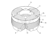
図1は本発明の実施例1のモーターステータの分解斜視図で、図2は本発明の実施例1のモーターステータの組み立てられた状態の断面図である。本発明のモーターステータはインナローラータイプのモーターステータまたはアウターロータータイプのモーターステータからなることができ、図1,2に示す本発明の実施例1においては、インナローラータイプのモーターステータが掲示されており、上記モーターステータには少なくとも一個の鉄心1a、一個のコイル2aおよび一個の防塵スリーブ3が含まれる。その中、鉄心1aはコイル2aを巻き付けて結合するのに用いられ、防塵スリーブ3は鉄心1aとコイル2aの間(すなわちコイル2aの外周)に嵌設して結合するように用いられる。
1 is an exploded perspective view of a motor stator according to a first embodiment of the present invention, and FIG. 2 is a cross-sectional view of the assembled motor stator according to the first embodiment of the present invention. The motor stator of the present invention can be composed of an inner roller type motor stator or an outer rotor type motor stator. In the first embodiment of the present invention shown in FIGS. 1 and 2, an inner roller type motor stator is posted. The motor stator includes at least one iron core 1a, one
鉄心1aは、例えば、粉末冶金、鋳造、プレス加工などの方式を採用して所定の形状を有する鉄心を一体成形するか、または、鉄心1aは複数個のシリコーン鋼片を互いに重ねてなるように構成することができる。ここにおいて、上述した所定の形状を有する鉄心1aとは、鉄心1aに軸方向に貫穿される一個の収容孔11と収容孔11に位置するように複数個の磁気感応部12が設けられることを指す。
The iron core 1a is formed by integrally forming an iron core having a predetermined shape by adopting, for example, powder metallurgy, casting, pressing, or the like, or the iron core 1a is formed by stacking a plurality of silicone steel pieces. Can be configured. Here, the iron core 1a having the above-mentioned predetermined shape means that a
実施例1において、鉄心1aは複数個のシリコーン鋼片を互いに重ねてなるように構成される。その中、複数個のシリコーン鋼片にはそれぞれ軸方向に貫穿するように一個の貫穿孔が設けられ、かつ、複数個のシリコーン鋼片の貫穿孔の内側の周壁に複数個の磁極端を設けることにより、複数個のシリコーン鋼片を互いに重ね合わせて結合して鉄心1aを構成した後、複数個のシリコーン鋼片の貫穿孔は協働して収容孔11を形成することができる。
In the first embodiment, the iron core 1a is configured such that a plurality of pieces of silicone steel are stacked on each other. Among them, a plurality of silicone steel pieces are each provided with one through-hole so as to penetrate in the axial direction, and a plurality of magnetic pole ends are provided on the inner peripheral wall of the plurality of silicone steel pieces. Thus, after the plurality of silicone steel pieces are overlapped and bonded to each other to form the iron core 1a, the through holes of the plurality of silicone steel pieces can cooperate to form the
また、複数個のシリコーン鋼片の複数個の磁極端はそれぞれ互いに重ねることにより、収容孔11に位置する複数個の磁気感応部12を構成することができる。さらに、鉄心1aが収容孔11の軸方向における両端には、好ましくは、それぞれ一個の絶縁部材13が設けられることにより、コイル2aと鉄心1aが結合した後、間接的に絶縁部材13を利用してコイル2aと鉄心1aが直接接触するのを防止することができるため、短絡の現象が生じるのを防止することができる。
In addition, the plurality of magnetic pole ends of the plurality of silicone steel pieces are overlapped with each other, whereby a plurality of magnetic
コイル2aは鉄心1aと結合し、かつ、複数個の磁気感応部12の間に貫穿するように設けられ、その中、コイル2aと鉄心1aの間には隙間Dが含まれる。本発明の実施例1において、コイル2aには一個の励磁部21と一個の整線部22が含まれ、励磁部21は複数個の磁気感応部12間に貫穿するように設けられる。整線部22はコイル2aが鉄心1aの収容孔11の外に集束される部位であり、隙間Dはコイル2aの整線部22と鉄心1aの間に形成される隙間である。さらに詳しく言えば、例えば、鉄心1aに絶縁部材13が設けられる時、隙間Dはコイル2aの整線部22と鉄心1aの絶縁部材13の間の隙間を指す。
The
防塵スリーブ3の相対する両端にはそれぞれ一個の開口31、32が設けられることにより、防塵スリーブ3はコイル2aと鉄心1aの間に嵌設して結合することができ、かつ、隙間Dを遮蔽するように形成され、さらにゴミが隙間Dを経て鉄心1aの内部に溜まるのを防止することができる。本発明の防塵スリーブ3は、好ましくは図に示すように、伸縮弾性を有するスリーブ、例えば、ゴムまたはシリコーンなどの材質により製造される弾性スリーブからなることにより、防塵スリーブ3の弾性作用を利用して各種のサイズの異なるステータの鉄心に嵌設して結合することができる。
By providing one opening 31 and 32 at opposite ends of the dust-
図3は本発明のモーターステータが放熱ファンに用いられる組み立てられた状態の断面図である。図3を参照すると、本発明のモーターステータが一個の放熱ファン4に応用される時の組み立てられた状態の断面を示す。その中、放熱ファン4には一個のフレーム基座41が設けられる。本発明の鉄心1aはフレーム基座41に固定され、かつ、フレーム基座41には一個の枢接軸411が設けられ、枢接軸411は一個のファンホイール42を枢接するのに用いられる。ファンホイール42の内側には一個の磁気伝導部材43が設置され、磁気伝導部材43は鉄心1aの収容孔11に位置するように形成され、かつ、磁気伝導部材43と複数個の磁気感応部12は相対するように形成される。
FIG. 3 is a sectional view of an assembled state in which the motor stator of the present invention is used for a heat radiating fan. Referring to FIG. 3, a cross-section of the assembled state when the motor stator of the present invention is applied to a single
これにより、本発明のモーターステータが通電された後、ファンホイール42が回転して作動するように駆動することができるため、所要の放熱作用を提供することができる。また、本発明のモーターステータをモーターの構造だけに応用することもでき、その場合、モーターの構造、前述した放熱ファンの詳細な構成および作動原理は全て本発明の技術分野に属する技術者が容易に理解することができるため、ここではその説明を省く。
Thereby, after the motor stator of the present invention is energized, the
また、本発明の防塵スリーブ3の一端の開口32は鉄心1aに向けるように形成され、もう一端の開口31は、好ましくは、コイル2aが露出するのに用いられる。これにより、防塵スリーブ3によってコイル2aと鉄心1aの間の隙間Dを閉止して遮蔽することができる。その中、本発明のモーターステータが放熱ファンまたはモーターに応用される時、モーターステータの上端はファンホイール42によって被覆されるため(図3の図式の方向を参照)、ゴミが直接モータースリーブの上端の隙間Dを経由して進入し、内部に溜まることにより、モーターの寿命が短くなり、かつ、回動時の騒音が大きくなるのを有効に避けることができる。このように、本発明の主な技術的概念は、コイル2aと鉄心1aの間に設置される防塵スリーブ3により、モーターステータによりよい防塵の効果を提供できることにある。
The
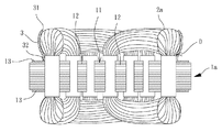
図4は本発明の実施例2のモーターステータの分解斜視図で、図5は本発明の実施例2のモーターステータの組み立てられた状態の外観図である。図4、5を参照すると、本発明の実施例2のアウターロータータイプのモーターステータには少なくとも一個の鉄心1b、一個のコイル2bおよび一個の防塵スリーブ3が含まれる。その中、鉄心1bはコイル2bが巻き付けるのに用いられ、防塵スリーブ3は鉄心1bとコイル2bの間に嵌設して結合するのに用いられる。
FIG. 4 is an exploded perspective view of the motor stator according to the second embodiment of the present invention, and FIG. 5 is an external view of the assembled motor stator according to the second embodiment of the present invention. 4 and 5, the outer rotor type motor stator according to the second embodiment of the present invention includes at least one iron core 1b, one
鉄心1bも同様に、例えば、粉末冶金、鋳造、プレス加工などの方式を採用して所定の形状を有する鉄心を一体成形するか、または、鉄心1bは複数個のシリコーン鋼片を互いに重ねてなるように構成することができる。ここにおいて、上述した所定の形状を有する鉄心1bとは、鉄心1bには軸方向に貫穿するように一個の収容孔11と鉄心1bの外周側に位置するように複数個の磁気感応部12が設けられることを指す。
Similarly, the iron core 1b is formed by integrally forming an iron core having a predetermined shape by adopting a method such as powder metallurgy, casting, or pressing, or the iron core 1b is formed by stacking a plurality of pieces of silicon steel. It can be constituted as follows. Here, the iron core 1b having the above-described predetermined shape means that the iron core 1b has one receiving
実施例2において、鉄心1bは複数個のシリコーン鋼片を互いに重ねてなるように構成される。その中、複数個のシリコーン鋼片にはそれぞれ軸方向に貫穿するように一個の貫穿孔が設けられ、かつ、複数個のシリコーン鋼片の外周側には複数個の磁極端が設けられる。これにより、複数個のシリコーン鋼片を互いに重ねて結合して鉄心1bを構成した後、複数個のシリコーン鋼片の貫穿孔は協働して収容孔11を形成することができる。
In the second embodiment, the iron core 1b is configured such that a plurality of pieces of silicone steel are stacked on each other. Among them, each of the plurality of silicone steel pieces is provided with one through-hole so as to penetrate in the axial direction, and a plurality of magnetic pole ends are provided on the outer peripheral side of the plurality of silicone steel pieces. Thus, after the plurality of silicone steel pieces are overlapped and joined together to form the iron core 1b, the through holes of the plurality of silicone steel pieces can cooperate to form the receiving
また、複数個のシリコーン鋼片の複数個の磁極端はそれぞれ互いに重ねることにより、鉄心1bの外周側に位置する複数個の磁気感応部12を構成することができる。さらに、鉄心1bが収容孔11の軸方向における両端には、好ましくは、それぞれ一個の絶縁部材13が設けられることにより、コイル2bと鉄心1bが結合した後、間接的に絶縁部材13を利用してコイル2bと鉄心1bが直接に接触するのを防止することができるため、短絡の現象が生じるのを予防することができる。
Moreover, the several magnetic
コイル2bは鉄心1bと結合し、かつ複数個の磁気感応部12の間に貫穿するように設けられるか、または、鉄心1bに、好ましくは、絶縁部材13が設けられる時、コイル2bが絶縁部材13によって間接的に複数個の磁気感応部12に巻き付けるように設けられる。さらに、コイル2bと鉄心1bの間には同様に隙間Dが含まれる。
The
防塵スリーブ3の相対する両端にはそれぞれ一個の開口31、32が設けられることにより、防塵スリーブ3はコイル2bと鉄心1bの間に嵌設して結合することができ、かつ、コイル2bと鉄心1bの間の隙間Dを遮蔽することができ、さらにゴミが隙間Dを経て鉄心1bの内部に溜まるのを防止することができる。その中、鉄心1bには、好ましくは絶縁部材13が設けられる時、防塵スリーブ3は、好ましくは絶縁部材13の外周側に嵌設することにより、コイル2bと鉄心1bの間の隙間Dを確実に遮蔽することができる。
By providing one
上述したように、本発明のモーターステータによれば、防塵スリーブ3を利用してコイル2a、2bと鉄心1a、1bの間の隙間Dを遮蔽することができるため、モーターステータが放熱ファンまたはモーターに応用される時、ゴミが鉄心1a、1bとコイル2a、2bの間の隙間Dを経由してモーターステータの内部に溜まるのを有効に防止できることにより、モーターステータが長期的に使用しても依然として正常な作動を維持することを確保できるため、使用上の寿命を高めることができる。
As described above, according to the motor stator of the present invention, since the gap D between the
また、特に防塵スリーブ3は、好ましくは弾性を有するスリーブの設計からなる場合、さらに防塵スリーブ3の弾性作用を利用して、各種のサイズの異なるステータの鉄心に簡単に嵌設して結合することができる。また、選択されるステータのコイル2aと鉄心1aの間の隙間Dの大きさや形状が変更しても、防塵スリーブ3も同様にそのものの弾性変形の特性を利用して合わせるように隙間Dを遮蔽することにより、よりよい遮蔽効果を提供することができる。このように、関係業者にとってサイズの異なるステータの鉄心に対して異なる防塵スリーブ3を準備する必要はなく、組立ての便利性を高めることができるとともに、遮蔽の効果を高めることができる。
In particular, when the dust-
本発明は、その精神及び必須の特徴事項から逸脱することなく他のやり方で実施することができる。従って、本明細書に記載した好ましい実施形態は例示のなものであり、限定のなものではない。 The present invention may be implemented in other ways without departing from the spirit and essential characteristics thereof. Accordingly, the preferred embodiments described herein are exemplary and not limiting.
1a 鉄心
1b 鉄心
11 収容孔
12 磁気感応部
13 絶縁部材
2a コイル
2b コイル
21 励磁部
22 整線部
3 防塵スリーブ
31 開口
32 開口
4 放熱ファン
41 フレーム基座
411 枢接軸
42 ファンホーゼル
43 磁気伝導部材
9 モーターステータ
91 鉄心
92 コイル
93 モーターコイルカバー
D 隙間
DESCRIPTION OF SYMBOLS 1a Iron core
Claims (5)
One opening (31, 32) is provided at each of the opposite ends of the dustproof sleeve (3), and the opening (32) at one end of the dustproof sleeve (3) is formed to face the iron core (1a), and the other end The motor stator according to claim 1, 2 or 3 , wherein the opening (31) is used to expose the coil (2a).
Applications Claiming Priority (2)
| Application Number | Priority Date | Filing Date | Title |
|---|---|---|---|
| TW101134361 | 2012-09-19 | ||
| TW101134361A TWI456867B (en) | 2012-09-19 | 2012-09-19 | Stator of motor |
Publications (2)
| Publication Number | Publication Date |
|---|---|
| JP2014064443A JP2014064443A (en) | 2014-04-10 |
| JP5773498B2 true JP5773498B2 (en) | 2015-09-02 |
Family
ID=47987632
Family Applications (1)
| Application Number | Title | Priority Date | Filing Date |
|---|---|---|---|
| JP2012219249A Expired - Fee Related JP5773498B2 (en) | 2012-09-19 | 2012-10-01 | Motor stator |
Country Status (4)
| Country | Link |
|---|---|
| US (1) | US20140077642A1 (en) |
| JP (1) | JP5773498B2 (en) |
| CN (2) | CN202856477U (en) |
| TW (1) | TWI456867B (en) |
Families Citing this family (2)
| Publication number | Priority date | Publication date | Assignee | Title |
|---|---|---|---|---|
| TWI456867B (en) * | 2012-09-19 | 2014-10-11 | Sunonwealth Electr Mach Ind Co | Stator of motor |
| FR3038160B1 (en) * | 2015-06-29 | 2019-08-02 | Valeo Systemes Thermiques | AIR PULSE DEVICE COMPRISING AN ELECTRIC MOTOR |
Family Cites Families (24)
| Publication number | Priority date | Publication date | Assignee | Title |
|---|---|---|---|---|
| USRE19106E (en) * | 1934-03-13 | Stator with insulation enclosed | ||
| US3002119A (en) * | 1956-12-13 | 1961-09-26 | Electrolux Ab | Insulated field winding for dynamo-electric machines and method of making same |
| JPS538713A (en) * | 1976-07-12 | 1978-01-26 | Mitsubishi Electric Corp | Manufacturing method of canned motor |
| JPS5488514U (en) * | 1977-12-05 | 1979-06-22 | ||
| JPS55166137U (en) * | 1979-05-15 | 1980-11-29 | ||
| JPS6086048U (en) * | 1983-11-17 | 1985-06-13 | 三洋電機株式会社 | Hermetic electric compressor |
| JPH05336702A (en) * | 1992-06-02 | 1993-12-17 | Toshiba Corp | Induction motor |
| JPH0613367U (en) * | 1992-07-21 | 1994-02-18 | 株式会社富士通ゼネラル | motor |
| JPH08172755A (en) * | 1994-12-16 | 1996-07-02 | Yaskawa Electric Corp | Open-type electric motor |
| JPH0956098A (en) * | 1995-08-21 | 1997-02-25 | Fujitsu General Ltd | Stator for motor |
| JPH11148484A (en) * | 1997-11-19 | 1999-06-02 | Toshiba Tec Corp | Electrically driven air blower |
| JP3261355B2 (en) * | 1998-07-27 | 2002-02-25 | 多摩川精機株式会社 | Resolver rotor coil protection structure |
| JP3347118B2 (en) * | 2000-01-26 | 2002-11-20 | 三菱電機株式会社 | AC generator |
| JP2004201366A (en) * | 2002-12-16 | 2004-07-15 | Hitachi Koki Co Ltd | Commutator motor |
| JP4108488B2 (en) * | 2003-01-17 | 2008-06-25 | 山洋電気株式会社 | Waterproof brushless fan motor |
| JP4029061B2 (en) * | 2003-05-19 | 2008-01-09 | 松下電器産業株式会社 | Compressor |
| TWM273127U (en) * | 2005-02-04 | 2005-08-11 | Ren-Jie Wu | Stator of motor with external rotor |
| TWI265666B (en) * | 2005-12-02 | 2006-11-01 | Delta Electronics Inc | Stator structure and manufacturing method thereof |
| CN101988525A (en) * | 2009-07-31 | 2011-03-23 | 上海卡固电气设备有限公司 | Fan |
| JP2011117321A (en) * | 2009-12-01 | 2011-06-16 | Mitsubishi Electric Corp | Hermetic compressor |
| JP2012055106A (en) * | 2010-09-02 | 2012-03-15 | Toyota Motor Corp | Rotary electric machine |
| TWI423562B (en) * | 2010-12-01 | 2014-01-11 | Sunonwealth Electr Mach Ind Co | Motor stator and the manufacturing method thereof |
| US8481877B2 (en) * | 2011-02-02 | 2013-07-09 | X' Pole Precision Tools Inc. | Dust-proof machine tools |
| TWI456867B (en) * | 2012-09-19 | 2014-10-11 | Sunonwealth Electr Mach Ind Co | Stator of motor |
-
2012
- 2012-09-19 TW TW101134361A patent/TWI456867B/en active
- 2012-10-01 JP JP2012219249A patent/JP5773498B2/en not_active Expired - Fee Related
- 2012-10-08 CN CN201220512389.4U patent/CN202856477U/en not_active Expired - Fee Related
- 2012-10-08 CN CN201210375913.2A patent/CN103683554A/en active Pending
-
2013
- 2013-05-17 US US13/896,433 patent/US20140077642A1/en not_active Abandoned
Also Published As
| Publication number | Publication date |
|---|---|
| JP2014064443A (en) | 2014-04-10 |
| TWI456867B (en) | 2014-10-11 |
| CN202856477U (en) | 2013-04-03 |
| CN103683554A (en) | 2014-03-26 |
| US20140077642A1 (en) | 2014-03-20 |
| TW201414140A (en) | 2014-04-01 |
Similar Documents
| Publication | Publication Date | Title |
|---|---|---|
| JP6343127B2 (en) | motor | |
| JP6398843B2 (en) | motor | |
| JP5930409B2 (en) | Rotating electric machine | |
| KR102349836B1 (en) | Brushless motor and stator therefor | |
| JP2015142484A (en) | Surface magnet type rotary electric machine | |
| JP2015122854A (en) | Inner rotor type motor | |
| JP6229147B2 (en) | Electric motor and compressor equipped with the same | |
| JP6102249B2 (en) | Single phase induction motor | |
| US10340758B2 (en) | Permanent magnet motor | |
| JP2008259383A (en) | Brushless motor | |
| JP5773498B2 (en) | Motor stator | |
| JP5439904B2 (en) | Rotating electric machine | |
| JPWO2017170297A1 (en) | motor | |
| TWI430539B (en) | Motor | |
| US11005333B2 (en) | Electric motor having a stator with a radially outside rotor with the rotor having a fan mounting portion comprising a noncontact region and a contract region configured to contact a mouting surface of a fan | |
| KR102554171B1 (en) | Rotor and motor having the same | |
| JP2017046369A (en) | Armature, manufacturing method of the same, and rotary electric machine | |
| JP2010110169A (en) | Rotor for electric rotary machine | |
| JP6013989B2 (en) | Rotating electric machine and assembling method thereof | |
| JP2013027150A (en) | Electric motor and compressor and apparatus including the same | |
| WO2021250735A1 (en) | Electric motor and blowing device | |
| JP2012253985A (en) | Motor | |
| WO2023199475A1 (en) | Motor | |
| JP6109052B2 (en) | Canned motor | |
| JP5855313B2 (en) | Motor and manufacturing method thereof |
Legal Events
| Date | Code | Title | Description |
|---|---|---|---|
| A601 | Written request for extension of time |
Free format text: JAPANESE INTERMEDIATE CODE: A601 Effective date: 20140219 |
|
| A521 | Request for written amendment filed |
Free format text: JAPANESE INTERMEDIATE CODE: A523 Effective date: 20140226 |
|
| A602 | Written permission of extension of time |
Free format text: JAPANESE INTERMEDIATE CODE: A602 Effective date: 20140305 |
|
| A131 | Notification of reasons for refusal |
Free format text: JAPANESE INTERMEDIATE CODE: A131 Effective date: 20140827 |
|
| A521 | Request for written amendment filed |
Free format text: JAPANESE INTERMEDIATE CODE: A523 Effective date: 20141126 |
|
| TRDD | Decision of grant or rejection written | ||
| A01 | Written decision to grant a patent or to grant a registration (utility model) |
Free format text: JAPANESE INTERMEDIATE CODE: A01 Effective date: 20150602 |
|
| A61 | First payment of annual fees (during grant procedure) |
Free format text: JAPANESE INTERMEDIATE CODE: A61 Effective date: 20150626 |
|
| R150 | Certificate of patent or registration of utility model |
Ref document number: 5773498 Country of ref document: JP Free format text: JAPANESE INTERMEDIATE CODE: R150 |
|
| LAPS | Cancellation because of no payment of annual fees |