JP5772934B2 - Data conversion apparatus, data conversion method, and computer program - Google Patents
Data conversion apparatus, data conversion method, and computer program Download PDFInfo
- Publication number
- JP5772934B2 JP5772934B2 JP2013249046A JP2013249046A JP5772934B2 JP 5772934 B2 JP5772934 B2 JP 5772934B2 JP 2013249046 A JP2013249046 A JP 2013249046A JP 2013249046 A JP2013249046 A JP 2013249046A JP 5772934 B2 JP5772934 B2 JP 5772934B2
- Authority
- JP
- Japan
- Prior art keywords
- data
- conversion
- unit
- linear
- nonlinear
- Prior art date
- Legal status (The legal status is an assumption and is not a legal conclusion. Google has not performed a legal analysis and makes no representation as to the accuracy of the status listed.)
- Expired - Fee Related
Links
Images


Description
本発明は、データ変換装置、およびデータ変換方法、並びにコンピュータ・プログラムに関する。さらに詳細には、例えば、共通鍵ブロック暗号処理に適用可能な非線形変換処理を行なう拡張Feistel型共通鍵ブロック暗号を適用したデータ変換装置、およびデータ変換方法、並びにコンピュータ・プログラムに関する。 The present invention relates to a data conversion device, a data conversion method, and a computer program. More specifically, for example, the present invention relates to a data conversion apparatus, a data conversion method, and a computer program to which an extended Feistel type common key block cipher that performs nonlinear conversion processing applicable to the common key block cipher processing is applied.
昨今、ネットワーク通信、電子商取引の発展に伴い、通信におけるセキュリティ確保が重要な問題となっている。セキュリティ確保の1つの方法が暗号技術であり、現在、様々な暗号化手法を用いた通信が実際に行なわれている。 In recent years, with the development of network communication and electronic commerce, ensuring security in communication has become an important issue. One method of ensuring security is encryption technology, and currently, communication using various encryption methods is actually performed.
例えばICカード等の小型の装置中に暗号処理モジュールを埋め込み、ICカードと、データ読み取り書き込み装置としてのリーダライタとの間でデータ送受信を行ない、認証処理、あるいは送受信データの暗号化、復号を行なうシステムが実用化されている。 For example, an encryption processing module is embedded in a small device such as an IC card, and data is transmitted / received between the IC card and a reader / writer as a data reading / writing device, and authentication processing or encryption / decryption of transmitted / received data is performed. The system has been put into practical use.
暗号処理アルゴリズムには様々なものがあるが、大きく分類すると、暗号化鍵と復号鍵を異なる鍵、例えば公開鍵と秘密鍵として設定する公開鍵暗号方式と、暗号化鍵と復号鍵を共通の鍵として設定する共通鍵暗号方式とに分類される。 There are various cryptographic processing algorithms, but broadly classified, the encryption key and the decryption key are different keys, for example, the public key cryptosystem that sets the public key and the private key, and the encryption key and the decryption key are common. It is classified into a common key encryption method set as a key.
共通鍵暗号方式にも様々なアルゴリズムがあるが、その1つに共通鍵をベースとして複数の鍵を生成して、生成した複数の鍵を用いてブロック単位(64ビット,128ビットなど)のデータ変換処理を繰り返し実行する方式がある。このような鍵生成方式とデータ変換処理を適用したアルゴリズムの代表的なものが共通鍵ブロック暗号方式である。 There are various algorithms in the common key cryptosystem, one of which generates a plurality of keys based on the common key, and uses the generated plurality of keys as a block unit (64 bits, 128 bits, etc.) data. There is a method for repeatedly executing the conversion process. A typical algorithm applying such a key generation method and data conversion processing is a common key block encryption method.
代表的な共通鍵ブロック暗号のアルゴリズムとしては、例えば過去に米国標準暗号であったDES(Data Encryption Standard)アルゴリズム、現在の米国標準暗号であるAES(Advanced Encryption Standard)アルゴリズムなどが知られている。 As a typical common key block cipher algorithm, for example, a DES (Data Encryption Standard) algorithm which has been a US standard cipher in the past, an AES (Advanced Encryption Standard) algorithm which is a current US standard cipher, and the like are known.
このような、共通鍵ブロック暗号のアルゴリズムは、主として、入力データの変換を繰り返し実行するラウンド関数実行部を有する暗号処理部と、ラウンド関数部の各ラウンドで適用するラウンド鍵を生成する鍵スケジューリング部とによって構成される。鍵スケジューリング部は、秘密鍵であるマスター鍵(主鍵)に基づいて、まずビット数を増加させた拡大鍵を生成し、生成した拡大鍵に基づいて、暗号処理部の各ラウンド関数部で適用するラウンド鍵(副鍵)を生成する。 Such a common key block cipher algorithm mainly includes an encryption processing unit having a round function execution unit that repeatedly executes conversion of input data, and a key scheduling unit that generates a round key applied in each round of the round function unit. It is comprised by. The key scheduling unit first generates an extended key with an increased number of bits based on a master key (primary key) that is a secret key, and applies it to each round function unit of the cryptographic processing unit based on the generated extended key. Generate a round key (subkey).
このようなアルゴリズムを実行する具体的な構造として、線形変換部および非線形変換部を有するラウンド関数を繰り返し実行する構造が知られている。例えば代表的な構造にFeistel構造がある。Feistel構造は、データ変換関数としてのラウンド関数(F関数)の単純な繰り返しにより、平文を暗号文に変換する構造を持つ。ラウンド関数(F関数)においては、線形変換処理および非線形変換処理が実行される。なお、Feistel構造を適用した暗号処理について記載した文献としては、例えば非特許文献1、非特許文献2がある。
As a specific structure for executing such an algorithm, a structure for repeatedly executing a round function having a linear conversion unit and a non-linear conversion unit is known. For example, a typical structure is a Feistel structure. The Feistel structure has a structure that converts plaintext into ciphertext by simple repetition of a round function (F function) as a data conversion function. In the round function (F function), linear transformation processing and nonlinear transformation processing are executed. Note that there are
この共通鍵ブロック暗号処理や、例えばハッシュ関数などでは非線形変換処理によるデータ変換が実行される。非線形変換にはSボックス(S−box)と呼ばれる非線形変換関数が適用可能である。Sボックスは、ブロック暗号やハッシュ関数の構成要素であり、その安全性や実装性能を決定付ける非常に重要な関数である。Sボックスは一般的にはn−bit入力、m−bit出力の非線形変換関数である。入出力ビット数が同数でかつ、入出力が1対1に対応しているSボックスは、全単射型Sボックスと呼ばれる。 Data conversion by non-linear conversion processing is executed in this common key block encryption processing, for example, a hash function. A nonlinear transformation function called an S box (S-box) can be applied to the nonlinear transformation. The S box is a component of a block cipher and a hash function, and is a very important function that determines its security and implementation performance. The S box is generally a non-linear transformation function with n-bit input and m-bit output. An S box having the same number of input / output bits and one-to-one input / output is called a bijective S box.
暗号処理の非線形変換にSボックスを適用する場合、適用するSボックスの性質は、暗号の安全性に大きな影響を与える。すなわち、例えば差分解析、線形解析など、様々な暗号攻撃が知られているが、このような暗号攻撃によって鍵やアルゴリズムが解析される困難性が高いほど安全性が高い。ブロック暗号やハッシュ関数に利用されるSボックスの性質によってこの安全性が大きく異なってくる。 When the S box is applied to non-linear transformation of cryptographic processing, the nature of the applied S box has a great influence on the security of the encryption. That is, various cryptographic attacks such as differential analysis and linear analysis are known, but the higher the difficulty with which a key or algorithm is analyzed by such a cryptographic attack, the higher the security. This security varies greatly depending on the nature of the S box used for block ciphers and hash functions.
例えば、暗号アルゴリズム全体や暗号処理に適用されるラウンド関数自体の厳密な安全性評価は、その入出力サイズが大きい(例えば64ビット、128ビットなど)ことから一般的に困難である。しかし、Sボックスの入出力サイズは一般的には小さい。例えば、8−bit入出力程度であり、厳密な安全性評価が可能となる。暗号アルゴリズム全体の安全性を高くするために、Sボックスには、少なくとも以下のような特性が求められることが知られている。
(1)最大差分確率が十分小さい
(2)最大線形確率が十分小さい
(3)ブール多項式表現を行った際のブール代数次数が十分大きい
(4)入出力を多項式表現した際の項数が十分多い
For example, strict security evaluation of the entire cryptographic algorithm and the round function itself applied to cryptographic processing is generally difficult because of its large input / output size (for example, 64 bits, 128 bits, etc.). However, the input / output size of the S box is generally small. For example, it is about 8-bit input / output, and strict safety evaluation is possible. In order to increase the security of the entire encryption algorithm, it is known that the S box requires at least the following characteristics.
(1) The maximum difference probability is sufficiently small. (2) The maximum linear probability is sufficiently small. (3) The Boolean algebraic degree when the Boolean polynomial expression is performed is sufficiently large. (4) The number of terms when the input / output polynomial expression is sufficient. Many
主に、(1)は差分攻撃に対する耐性、(2)は線形攻撃に対する耐性、(3)は高階差分攻撃に対する耐性、(4)は補間攻撃に対する耐性をそれぞれ決定付ける。さらには、Sボックスの入出力のビット相関が低いことや入力を1ビット変化させたときの出力の変化が1/2程度になることなどが安全性を高めるために重要である。 Mainly, (1) determines resistance to differential attacks, (2) determines resistance to linear attacks, (3) determines resistance to higher order differential attacks, and (4) determines resistance to interpolation attacks. Furthermore, it is important to improve safety that the bit correlation between the input and output of the S box is low and that the change in output when the input is changed by 1 bit is about ½.
また、Sボックスは安全性の要求とは別に高い実装性能も要求される。例えば、ソフトウェアによる暗号処理やハッシュ関数を実行させる実装構成においては通常、入力に対する出力を示すテーブルをメモリに保持して、表引き(テーブル実装)と呼ばれる手法により、非線形変換処理を実行する構成とした実装がなされるため、その実装性能はSボックスの内部構造にはあまり依存しない。しかしながら、ハードウェア実装においては、例えば入力値に基づいて、特定の出力を算出するための回路が構成される。この回路構成は、適用するSボックスにより、構成が大きく変化することになり、回路規模に影響を与えることになる。 Further, the S box is required to have high mounting performance in addition to the safety requirement. For example, in an implementation configuration that executes cryptographic processing by software or a hash function, a configuration in which a table indicating an output with respect to an input is normally held in a memory, and a nonlinear conversion process is executed by a technique called table lookup (table implementation) Therefore, the mounting performance does not depend much on the internal structure of the S box. However, in hardware implementation, for example, a circuit for calculating a specific output is configured based on an input value. This circuit configuration greatly changes depending on the S box to be applied, and affects the circuit scale.
本発明は、上記問題点に鑑みてなされたものであり、暗号処理などにおいて利用される非線形変換処理を実行するSボックスの構成を改良し、各種の攻撃に対する耐性を高めた構成、すなわち安全性の高めた拡張Feistel型共通鍵ブロック暗号を適用した暗号処理等を実行するデータ変換装置、およびデータ変換方法、並びにコンピュータ・プログラムを提供することを目的とする。 The present invention has been made in view of the above-described problems, and has improved the configuration of the S box that executes nonlinear transformation processing used in cryptographic processing and the like, that is, a configuration with improved resistance to various attacks, that is, safety. An object of the present invention is to provide a data conversion apparatus, a data conversion method, and a computer program that execute cryptographic processing using the enhanced Feistel-type common key block cipher.
本発明の第1の側面は、
データ変換装置であり、
入力データを分割した分割データ各々の非線形変換処理を実行する複数の小型非線形変換部からなる第1段非線形変換部と、
前記第1段非線形変換部を構成する複数の小型非線形変換部からの出力をすべて入力して線形変換を実行する線形変換部と、
前記線形変換部の出力データを分割した分割データ各々の非線形変換処理を実行する複数の小型非線形変換部からなる第2段非線形変換部とを有し、
前記線形変換部は、
前記入力データのビットサイズと同サイズの要素を持つ行列演算によるデータ変換を実行する構成であり、行列がm×m行列である場合、少なくともm以上の分岐数を有する高分岐数の行列を適用したデータ変換処理を実行する構成であることを特徴とするデータ変換装置にある。
The first aspect of the present invention is:
A data converter,
A first-stage non-linear conversion unit comprising a plurality of small non-linear conversion units for executing non-linear conversion processing of each divided data obtained by dividing input data;
A linear conversion unit that performs linear conversion by inputting all outputs from a plurality of small non-linear conversion units constituting the first stage nonlinear conversion unit;
A second-stage non-linear conversion unit composed of a plurality of small non-linear conversion units that execute non-linear conversion processing of each of the divided data obtained by dividing the output data of the linear conversion unit,
The linear conversion unit includes:
It is a configuration that performs data conversion by matrix operation having an element of the same size as the bit size of the input data. When the matrix is an m × m matrix, a high-branch number matrix having at least m branches is applied. The data conversion apparatus is configured to execute the data conversion process performed.
さらに、本発明のデータ変換装置の一実施態様において、前記入力データがnビットデータである場合、前記第1非線形変換部は、入力データであるnビットデータの分割データであるn/kビットを各々入力して非線形変換処理結果としてのn/kビットを出力するk個の小型非線形変換部から構成され、前記線形変換部は、前記k個の小型非線形変換部の出力する総計nビットのデータを入力して、高分岐数の行列を適用したデータ変換処理によりnビットの出力を生成する構成であり、前記第2非線形変換部は、前記線形変換部から出力されるnビットデータの分割データであるn/kビットを各々入力して非線形変換処理結果としてのn/kビットを出力するk個の小型非線形変換部を有する構成であることを特徴とする。 Furthermore, in one embodiment of the data conversion apparatus of the present invention, when the input data is n-bit data, the first nonlinear conversion unit outputs n / k bits that are divided data of n-bit data that is input data. It is composed of k small non-linear conversion units that each input and output n / k bits as a result of the non-linear conversion processing, and the linear conversion unit outputs total n-bit data output from the k small non-linear conversion units. , And an n-bit output is generated by a data conversion process using a high-branch number matrix, and the second nonlinear conversion unit outputs divided data of n-bit data output from the linear conversion unit It is characterized by having k small non-linear conversion units that respectively input n / k bits and output n / k bits as a result of non-linear conversion processing.
さらに、本発明のデータ変換装置の一実施態様において、前記線形変換部は、最適拡散変換(ODM(Optimal Diffusion Mappings))処理を実行するMDS(Maximum Distance Separable)行列を適用したデータ変換処理を実行する構成であることを特徴とする。 Furthermore, in an embodiment of the data conversion apparatus of the present invention, the linear conversion unit performs a data conversion process using an MDS (Maximum Distance Separable) matrix that performs an optimal diffusion conversion (ODM) process. It is the structure which carries out.
さらに、本発明のデータ変換装置の一実施態様において、前記線形変換部は、前記入力データがnビットデータである場合、GF(2)上で定義されるn次の既約多項式p(x)によって定義される拡大体GF(2n)上の行列を適用したデータ変換処理を実行する構成であることを特徴とする。 Furthermore, in one embodiment of the data conversion apparatus of the present invention, the linear conversion unit includes an n-th irreducible polynomial p (x) defined on GF (2) when the input data is n-bit data. The data conversion process is performed by applying a matrix on the extension field GF (2 n ) defined by
さらに、本発明のデータ変換装置の一実施態様において、前記データ変換装置は、nビット入出力の非線形変換処理を実行するSボックスであり、前記第1段非線形変換部と、前記第2段非線形変換部に含まれる複数の小型非線形変換部は、nビットより少ないビット数の非線形変換処理を実行する小型のSボックスによって構成されていることを特徴とする。 Furthermore, in an embodiment of the data conversion apparatus of the present invention, the data conversion apparatus is an S box that executes an n-bit input / output nonlinear conversion process, and the first-stage nonlinear converter and the second-stage nonlinear converter The plurality of small non-linear conversion units included in the conversion unit are configured by a small S box that performs non-linear conversion processing with a bit number smaller than n bits.
さらに、本発明のデータ変換装置の一実施態様において、前記データ変換装置は、非線形変換処理を伴う暗号処理を実行する構成であることを特徴とする。 Furthermore, in one embodiment of the data conversion apparatus of the present invention, the data conversion apparatus is configured to execute a cryptographic process involving a nonlinear conversion process.
さらに、本発明のデータ変換装置の一実施態様において、前記暗号処理は、共通鍵ブロック暗号処理であることを特徴とする。 Furthermore, in an embodiment of the data conversion apparatus of the present invention, the encryption process is a common key block encryption process.
さらに、本発明の第2の側面は、
データ変換装置において実行するデータ変換方法であり、
第1段非線形変換部において、複数の小型非線形変換部を適用して、入力データを分割した分割データ各々の非線形変換処理を実行する第1段非線形変換ステップと、
線形変換部において、前記第1段非線形変換部を構成する複数の小型非線形変換部からの出力をすべて入力して線形変換を実行する線形変換ステップと、
第2段非線形変換部において、複数の小型非線形変換部を適用して、前記線形変換部の出力データを分割した分割データ各々の非線形変換処理を実行する第2段非線形変換ステップとを有し、
前記線形変換ステップは、
前記入力データのビットサイズと同サイズの要素を持つ行列演算によるデータ変換を実行する構成であり、行列がm×m行列である場合、少なくともm以上の分岐数を有する高分岐数の行列を適用したデータ変換処理を実行するステップであることを特徴とするデータ変換方法にある。
Furthermore, the second aspect of the present invention provides
A data conversion method executed in the data conversion device,
A first-stage non-linear conversion unit that applies a plurality of small non-linear conversion units to perform a non-linear conversion process on each of the divided data obtained by dividing the input data;
In the linear conversion unit, a linear conversion step for performing linear conversion by inputting all the outputs from the plurality of small nonlinear conversion units constituting the first stage nonlinear conversion unit;
A second-stage non-linear conversion unit that applies a plurality of small non-linear conversion units to perform a non-linear conversion process for each of the divided data obtained by dividing the output data of the linear conversion unit,
The linear transformation step includes
It is a configuration that performs data conversion by matrix operation having an element of the same size as the bit size of the input data. When the matrix is an m × m matrix, a high-branch number matrix having at least m branches is applied. According to another aspect of the present invention, there is provided a data conversion method characterized in that the data conversion process is a step of executing the data conversion process.
さらに、本発明の第3の側面は、
データ変換装置においてデータ変換処理を実行させるコンピュータ・プログラムであり、
第1段非線形変換部において、複数の小型非線形変換部を適用して、入力データを分割した分割データ各々の非線形変換処理を実行させる第1段非線形変換ステップと、
線形変換部において、前記第1段非線形変換部を構成する複数の小型非線形変換部からの出力をすべて入力して線形変換を実行させる線形変換ステップと、
第2段非線形変換部において、複数の小型非線形変換部を適用して、前記線形変換部の出力データを分割した分割データ各々の非線形変換処理を実行させる第2段非線形変換ステップとを有し、
前記線形変換ステップは、
前記入力データのビットサイズと同サイズの要素を持つ行列演算によるデータ変換を実行する構成であり、行列がm×m行列である場合、少なくともm以上の分岐数を有する高分岐数の行列を適用したデータ変換処理を実行させるステップであることを特徴とするコンピュータ・プログラムにある。
Furthermore, the third aspect of the present invention provides
A computer program for executing data conversion processing in a data conversion device,
A first-stage non-linear conversion unit that applies a plurality of small non-linear conversion units to execute non-linear conversion processing of each divided data obtained by dividing the input data;
In the linear conversion unit, a linear conversion step for executing linear conversion by inputting all the outputs from the plurality of small nonlinear conversion units constituting the first stage nonlinear conversion unit;
A second-stage non-linear conversion unit that applies a plurality of small non-linear conversion units to execute a non-linear conversion process for each of the divided data obtained by dividing the output data of the linear conversion unit;
The linear transformation step includes
It is a configuration that performs data conversion by matrix operation having an element of the same size as the bit size of the input data. When the matrix is an m × m matrix, a high-branch number matrix having at least m branches is applied. The present invention resides in a computer program characterized in that the data conversion process is executed.
なお、本発明のコンピュータ・プログラムは、例えば、様々なプログラム・コードを実行可能なコンピュータ・システムに対して、コンピュータ可読な形式で提供する記憶媒体、通信媒体、例えば、CDやFD、MOなどの記録媒体、あるいは、ネットワークなどの通信媒体によって提供可能なコンピュータ・プログラムである。このようなプログラムをコンピュータ可読な形式で提供することにより、コンピュータ・システム上でプログラムに応じた処理が実現される。 The computer program of the present invention is, for example, a storage medium or communication medium provided in a computer-readable format to a computer system capable of executing various program codes, such as a CD, FD, or MO. It is a computer program that can be provided by a recording medium or a communication medium such as a network. By providing such a program in a computer-readable format, processing corresponding to the program is realized on the computer system.
本発明のさらに他の目的、特徴や利点は、後述する本発明の実施例や添付する図面に基づくより詳細な説明によって明らかになるであろう。なお、本明細書においてシステムとは、複数の装置の論理的集合構成であり、各構成の装置が同一筐体内にあるものには限らない。 Other objects, features, and advantages of the present invention will become apparent from a more detailed description based on embodiments of the present invention described later and the accompanying drawings. In this specification, the system is a logical set configuration of a plurality of devices, and is not limited to one in which the devices of each configuration are in the same casing.
本発明の一実施例の構成によれば、例えば、共通鍵ブロック暗号を適用した暗号処理などにおいて実行される非線形変換処理を、複数の小さなSボックス(S−box)による非線形変換を実行する第1段の非線形変換部と、第1段非線形変換部からの出力をすべて入力して線形変換を実行する線形変換部と、線形変換部の出力データを分割した分割データ各々の非線形変換処理を実行する複数の小型非線形変換部からなる第2段非線形変換部とを適用したデータ変換を行う構成とし、線形変換部では、最適拡散変換を行う行列を適用したデータ変換を実行する構成としたので、データの入力から出力に至るクリティカルパスを過大にすることなく、適切なデータ拡散を実現して、各種の暗号攻撃に対する耐性の強い安全性の高いデータ変換を実現することができる。 According to the configuration of one embodiment of the present invention, for example, a nonlinear transformation process executed in a cryptographic process to which a common key block cipher is applied is executed by a nonlinear transformation process using a plurality of small S boxes (S-boxes). Non-linear conversion processing for each of the divided data obtained by dividing the output data of the linear conversion unit, the linear conversion unit that inputs all the outputs from the first-stage non-linear conversion unit and performs the linear conversion Since it is configured to perform data conversion using a second-stage nonlinear conversion unit composed of a plurality of small nonlinear conversion units, and the linear conversion unit is configured to perform data conversion using a matrix that performs optimal diffusion conversion. Realize appropriate data diffusion without overlying the critical path from data input to output, and secure and highly secure data conversion against various cryptographic attacks It can be realized.
以下、本発明の詳細について説明する。説明は、以下の項目に従って行なう。
1.共通鍵ブロック暗号の概要
2.暗号攻撃の概要
3.複数の小型Sボックスの組み合わせからなる非線形変換処理構成
(3−1)複数の小型Sボックスの組み合わせからなる非線形変換処理構成の有効性について
(3−2)従来型の複数の小型Sボックスの組み合わせからなる非線形変換処理構成と問題点
(3−3)本発明に係る複数の小型Sボックスの組み合わせからなる非線形変換処理構成
4.暗号処理装置の構成例
Details of the present invention will be described below. The description will be made according to the following items.
1. 1. Overview of common
[1.共通鍵ブロック暗号の概要]
まず、本発明の適用可能な通鍵ブロック暗号の概要について説明する。本明細書において、共通鍵ブロック暗号(以下ではブロック暗号)は、以下に定義するものを指すものとする。
[1. Overview of common key block cipher]
First, an outline of a key-pass block cipher applicable to the present invention will be described. In this specification, the common key block cipher (hereinafter referred to as block cipher) refers to the one defined below.
ブロック暗号は平文Pと鍵Kを入力し、暗号文Cを出力する。平文と暗号文のビット長をブロックサイズと呼びここではnで示す。nは任意の整数値を取りうるが、通常、ブロック暗号アルゴリズムごとに、予め1つに決められている値である。ブロック長がnのブロック暗号のことをnビットブロック暗号と呼ぶこともある。 In block cipher, plaintext P and key K are input and ciphertext C is output. The bit length of plaintext and ciphertext is called a block size and is denoted by n here. Although n can take an arbitrary integer value, it is usually a predetermined value for each block cipher algorithm. A block cipher with a block length of n is sometimes called an n-bit block cipher.
鍵のビット長は、kで表す。鍵は任意の整数値を取りうる。共通鍵ブロック暗号アルゴリズムは1つまたは複数の鍵サイズに対応することになる。例えば、あるブロック暗号アルゴリズムAはブロックサイズn=128であり、鍵のビット長k=128、またはk=192またはk=256の各種の鍵サイズに対応するという構成もありうる。
平文[P]、暗号文[C]、鍵[K]の各ビットサイズは、以下のように示される。
平文P:nビット
暗号文C:nビット
鍵K:kビット
The bit length of the key is represented by k. The key can take any integer value. The common key block cipher algorithm will correspond to one or more key sizes. For example, a certain block cipher algorithm A has a block size n = 128, and may correspond to various key sizes of a key bit length k = 128, or k = 192 or k = 256.
The bit sizes of plaintext [P], ciphertext [C], and key [K] are indicated as follows.
Plaintext P: n bits Ciphertext C: n bits Key K: k bits
図1にkビットの鍵長に対応したnビット共通鍵ブロック暗号アルゴリズムEの図を示す。図1に示すように、共通鍵ブロック暗号処理部E10は、nビットの平文Pと、kビットの鍵Kを入力して、予め定められた暗号アルゴリズムを実行して、nビットの暗号文Cを出力する。なお、図1には平文から暗号文を生成する暗号化処理のみを示している。暗号文から平文を生成する復号処理は、一般的には暗号処理部E10の逆関数が用いられる。ただし、暗号処理部E10の構造によっては、復号処理においても、同様の共通鍵ブロック暗号処理部E10が適用でき、鍵の入力順などのシーケンスの変更によって復号処理が可能となる。 FIG. 1 shows a diagram of an n-bit common key block cipher algorithm E corresponding to a key length of k bits. As shown in FIG. 1, the common key block cipher processing unit E10 inputs an n-bit plaintext P and a k-bit key K, executes a predetermined encryption algorithm, and performs an n-bit ciphertext C. Is output. FIG. 1 shows only an encryption process for generating ciphertext from plaintext. In general, the inverse function of the encryption processing unit E10 is used for the decryption processing for generating plaintext from the ciphertext. However, depending on the structure of the encryption processing unit E10, the same common key block encryption processing unit E10 can be applied in the decryption process, and the decryption process can be performed by changing the sequence such as the key input order.
図1に示す共通鍵ブロック暗号処理部E10の内部構成について、図2を参照して説明する。ブロック暗号は2つの部分に分けて考えることができる。ひとつは鍵Kを入力とし、ある定められたステップにより入力鍵Kのビット長を拡大して拡大鍵K'(ビット長k')を出力する鍵スケジューリング部11と、平文Pと鍵スケジューリング部11から入力する拡大鍵K'を受け取り、平文Pを入力して、拡大鍵K'を適用した暗号処理を実行して、暗号文Cを生成するためのデータの変換を実行する暗号処理部12である。なお、先に説明したように、暗号処理部12の構造によっては、暗号文を平文に戻すデータ復号処理にも暗号処理部12が適用可能な場合もある。
The internal configuration of the common key block cipher processing unit E10 shown in FIG. 1 will be described with reference to FIG. Block ciphers can be considered in two parts. One is a key scheduling unit 11 that takes a key K as an input, expands the bit length of the input key K by a predetermined step, and outputs an expanded key K ′ (bit length k ′), and a plaintext P and a key scheduling unit 11. The
次に、図2に示す暗号処理部12の詳細構成について図3を参照して説明する。暗号処理部12は、図3に示すように、ラウンド関数実行部20を適用したデータ変換を繰り返し実行する構成を持つ。すなわち、暗号処理部12は、ラウンド関数実行部20という処理単位に分割できる。ラウンド関数実行部20は入力として、前段のラウンド関数実行部の出力Xiと、拡大鍵に基づいて生成されるラウンド鍵RKiの2つのデータを受け取り、内部でデータ変換処理を実行して出力データXi+1を次のラウンド関数実行部に出力する。なお、第1ラウンドでは、入力は、平文または平文に対する初期化処理データである。また最終ラウンドの出力は暗号文となる。
Next, the detailed configuration of the
図3に示す例では、暗号処理部12は、r個のラウンド関数実行部20を有し、r回のラウンド関数実行部におけるデータ変換を繰り返して暗号文を生成する構成となっている。ラウンド関数の繰り返し回数をラウンド数と呼ぶ。図に示す例では、ラウンド数はrとなる。
In the example illustrated in FIG. 3, the
各ラウンド関数実行部の入力データXiは暗号化途中のnビットデータであり、あるラウンドにおけるラウンド関数の出力Xi+1が次のラウンドの入力として供給される。各ラウンド関数実行部のもう一つの入力データは鍵スケジュールから出力された拡大鍵のK'に基づくデータが用いられる。この各ラウンド関数実行部に入力され、ラウンド関数の実行に適用される鍵をラウンド鍵と呼ぶ。図で、iラウンドに適用するラウンド鍵をRKiとして示している。拡大鍵K'は、例えば、rラウンド分のラウンド鍵RK1〜RKrの連結データとして構成される。
The input data X i of each round function execution unit is n-bit data being encrypted, and the output X i + 1 of the round function in a certain round is supplied as the input of the next round. As another input data of each round function execution unit, data based on K ′ of the extended key output from the key schedule is used. A key that is input to each round function execution unit and applied to the execution of the round function is called a round key. In the figure, a round key applied to i-round is indicated as RK i . The expanded key K 'is configured as, for example, concatenated data of
図3に示す構成は、暗号処理部12の入力側から見て1ラウンド目の入力データをX0とし、i番目のラウンド関数から出力されるデータをXi、ラウンド鍵をRKiとして示した暗号処理部12の構成である。なお、この暗号処理部12の構造によっては、例えば、適用するラウンド鍵の適用シーケンスを、暗号化処理と逆に設定し、暗号文を暗号処理部12に入力することで、復号文を出力する構成にできる。
In the configuration shown in FIG. 3, the input data of the first round as viewed from the input side of the
図3に示す暗号処理部12のラウンド関数実行部20は、さまざまな形態をとりうる。ラウンド関数はその暗号アルゴリズムが採用する構造(structure)によって分類できる。代表的な構造として、
(ア)SPN(Substitution Permutation Network)構造、
(イ)Feistel構造、
(ウ)拡張Feistel構造、
がある。以下、これらの具体的構成について、図4〜図6を参照して説明する。
The round
(A) SPN (Substitution Permutation Network) structure,
(A) Feistel structure,
(C) Extended Feistel structure,
There is. Hereinafter, these specific structures will be described with reference to FIGS.
(ア)SPN構造ラウンド関数
まず、図4を参照して、ラウンド関数実行部20の一構成例としてのSPN構造ラウンド関数について説明する。SPN構造ラウンド関数実行部20aは、非線形変換層(S層)と線形変換層(P層)を接続したいわゆるSP型の構成を有する。図4に示すように、nビットの入力データすべてに対して、ラウンド鍵との排他的論理和(XOR)演算を実行する排他的論理和演算部21、排他的論理和演算部21の演算結果を入力し、入力データの非線形変換を実行する非線形変換処理部22、非線形変換処理部22における非線形変換処理結果を入力し、入力データに対する線形変換処理を実行する線形変換処理部23などによって構成される。線形変換処理部23の線形変換処理結果が、次のラウンドに出力される。最終ラウンドでは暗号文となる。なお、図4に示す例では、排他的論理和演算部21、非線形変換処理部22、線形変換処理部23の処理順を示しているが、これらの処理部の順番は、限定されるものではなく、他のシーケンスで処理を行なう構成としてもよい。
(A) SPN structure round function First, with reference to FIG. 4, the SPN structure round function as an example of 1 structure of the round
(イ)Feistel構造
次に、図5を参照してラウンド関数実行部20の一構成例としてのFeistel(フェイステル)構造について説明する。Feistel構造は、図5に示すように、前ラウンドからの入力(第1ラウンドでは入力文)であるnビットの入力データをn/2ビットの2つのデータに分割して、各ラウンドにおいて入れ替えながら処理を実行する。
(A) Feistel structure Next, a Feistel structure as one configuration example of the round
Feistel構造を持つラウンド関数実行部20bを適用した処理においては、図に示すように、一方のn/2ビットデータとラウンド鍵とがF関数部30に入力される。F関数部30は、上述したSPN構造と同様、非線形変換層(S層)と線形変換層(P層)を接続したいわゆるSP型の構成を有する。
In the processing to which the round
前ラウンドからのn/2ビットデータとラウンド鍵とがF関数部30の排他的論理和演算部31に入力され排他的論理和(XOR)処理がなされる。さらに、この結果データを非線形変換処理部32に入力して非線形変換を実行し、さらに、この非線形変換結果が線形変換処理部33に入力され線形変換が実行される。この線形変換結果が、F関数処理結果データとして出力する。
The n / 2-bit data and the round key from the previous round are input to the exclusive OR
さらに、このF関数出力と、前ラウンドから入力するもう1つのn/2ビット入力とを、排他的論理和演算部34に入力し、排他的論理和演算(XOR)を実行して、実行結果を、次のラウンドにおけるF関数の入力として設定される。なお、図に示す第iラウンドにおけるF関数入力に設定されたn/2ビットは次のラウンドのF関数出力との排他的論理和演算に適用される。このように、Feistel構造は、各ラウンドにおいて入力を交互に入れ替えながらF関数を適用したデータ変換処理を実行する。
Further, this F function output and another n / 2-bit input input from the previous round are input to the exclusive OR
(ウ)拡張Feistel構造
次に、図6を参照してラウンド関数実行部20の一構成例としての拡張Feistel構造について説明する。先に、図5を参照して説明したFeistel構造は、nビットの平文を2つに分割してn/2ビットずつに区分して処理を実行していた。すなわち、分割数:d=2とした処理である。なお、この分割数は、データ系列数とも呼ばれる。
(C) Extended Feistel Structure Next, an extended Feistel structure as one configuration example of the round
拡張Feistel構造では、このデータ系列数(分割数)dを3以上の任意の整数とした設定である。データ系列数(分割数)dの値に応じたさまざまな拡張Feistel構造を定義することができる。図6に示す例では、データ系列数(分割数)d=4であり、各系列に対してn/4ビットのデータが入力される。各ラウンドでは、1つ以上のラウンド関数としてのF関数が実行される。図に示す例は、1ラウンドにおいて2つのF関数部によるラウンド演算を行なう構成例である。 In the extended Feistel structure, the number of data series (number of divisions) d is set to an arbitrary integer of 3 or more. Various extended Feistel structures can be defined according to the value of the number of data series (number of divisions) d. In the example shown in FIG. 6, the number of data series (number of divisions) d = 4, and n / 4-bit data is input to each series. In each round, an F function as one or more round functions is executed. The example shown in the figure is a configuration example in which round calculation is performed by two F function units in one round.
F関数部41,42の構成は、先に図5を参照して説明したF関数部30の構成と同様であり、ラウンド鍵と入力値との排他的論理和演算と、非線形変換処理、線形変換処理を実行する構成となっている。なお、各F関数部に入力するラウンド鍵は、入力ビットとビット数が一致するように調整される。図に示す例では、各F関数部41,42に入力するラウンド鍵は、n/4ビットとなる。これらの鍵は、拡大鍵を構成するラウンド鍵をさらにビット分割して生成する。なお、データ系列数(分割数)をdとしたとき、各系列に入力されるデータはn/dビットであり、各F関数に入力する鍵のビット数もn/dビットに調整される。
The configuration of the
なお、図6に示す拡張Feistel構造では、データ系列数(分割数)をdとして、各ラウンドにおいてd/2のF関数を並列に実行する構成例であるが、拡張Feistel構造は、各ラウンドにおいて、1つ以上d/2以下のF関数を実行する構成が可能である。 The extended Feistel structure shown in FIG. 6 is a configuration example in which the number of data series (number of divisions) is d and an F function of d / 2 is executed in parallel in each round. However, the extended Feistel structure is in each round. One or more F / 2 functions can be executed.
図4〜図6を参照して説明したように、共通鍵ブロック暗号における暗号処理部12のラウンド関数実行部20は、
(ア)SPN(Substitution Permutation Network)構造、
(イ)Feistel構造、
(ウ)拡張Feistel構造、
これらの構造をとり得る。これらのラウンド関数実行部は、いずれも非線形変換層(S層)と線形変換層(P層)を接続したいわゆるSP型の構成を有する。すなわち、非線形変換処理を実行する非線形変換処理部と、線形変換処理を実行する線形変換処理部とを有する。以下、これらの変換処理構成について説明する。
As described with reference to FIGS. 4 to 6, the round
(A) SPN (Substitution Permutation Network) structure,
(A) Feistel structure,
(C) Extended Feistel structure,
These structures can be taken. Each of these round function execution units has a so-called SP type configuration in which a nonlinear conversion layer (S layer) and a linear conversion layer (P layer) are connected. That is, it has a non-linear conversion processing unit that executes non-linear conversion processing and a linear conversion processing unit that executes linear conversion processing. Hereinafter, these conversion processing configurations will be described.
(非線形変換処理部)
非線形変換処理部の具体例について、図7を参照して説明する。図7に示すように、非線形変換処理部50は、具体的には、Sボックス(S−box)51と呼ばれるsビット入力sビット出力の非線形変換テーブルがm個並んだものであり、msビットの入力データがsビットずつ分割されてそれぞれ対応するSボックス(S−box)51に入力されデータが変換される。各Sボックス51では、例えば変換テーブルを適用した非線形変換処理が実行される。
(Nonlinear transformation processing part)
A specific example of the nonlinear conversion processing unit will be described with reference to FIG. As shown in FIG. 7, the non-linear
入力されるデータのサイズが大きくなると実装上のコストが高くなる傾向がある。それを回避するために、図7に示すように、処理対象データXを複数の単位に分割し、それぞれに対して、非線形変換を施す構成がとられることが多い。例えば入力サイズをmsビットとしたとき、sビットずつのm個のデータに分割して、m個のSボックス(S−box)51それぞれに対してsビットを入力し、例えば変換テーブルを適用した非線形変換処理を実行して、これらの各Sビット出力m個を合成してmsビットの非線形変換結果を得る。 When the size of the input data increases, the implementation cost tends to increase. In order to avoid this, as shown in FIG. 7, it is often the case that the processing target data X is divided into a plurality of units and nonlinear conversion is performed on each of them. For example, when the input size is ms bits, the data is divided into m data of s bits, s bits are input to each of m S boxes (S-boxes) 51, and a conversion table is applied, for example. A non-linear conversion process is executed, and each of these S bit outputs m is synthesized to obtain an ms-bit non-linear conversion result.
(線形変換処理部)
線形変換処理部の具体例について、図8を参照して説明する。線形変換処理部は、入力値、例えば、Sボックスからの出力データであるmsビットの出力値を入力値Xとして入力し、この入力に対して線形変換を施しmsビットの結果を出力する。線形変換処理は、例えば、入力ビット位置の入れ替え処理などの線形変換処理を実行して、msビットの出力値Yを出力する。線形変換処理は、例えば、入力に対して、線形変換行列を適用して入力ビット位置の入れ替え処理を行なう。この行列の一例が図8に示す線形変換行列である。
(Linear transformation processor)
A specific example of the linear conversion processing unit will be described with reference to FIG. The linear transformation processing unit inputs an input value, for example, an ms-bit output value, which is output data from the S box, as an input value X, performs linear transformation on this input, and outputs an ms-bit result. In the linear conversion process, for example, a linear conversion process such as an input bit position replacement process is performed, and an ms-bit output value Y is output. In the linear conversion process, for example, the input bit position is replaced by applying a linear conversion matrix to the input. An example of this matrix is the linear transformation matrix shown in FIG.
線形変換処理部において適用する線形変換行列の要素は拡大体:GF(28)の体の要素やGF(2)の要素など、一般的にはさまざまな表現を適用した行列として構成できる。図8は、msビット入出力をもち、GF(2s)の上で定義されるm×mの行列により定義される線形変換処理部の1つの構成例を示すものである。 In general, the elements of the linear transformation matrix applied in the linear transformation processing unit can be configured as a matrix to which various expressions are applied, such as a body element of an extension field: GF (2 8 ) and an element of GF (2). FIG. 8 shows an example of the configuration of a linear conversion processing unit having an ms-bit input / output and defined by an m × m matrix defined on GF (2 s ).
[2.暗号攻撃の概要]
上述した共通鍵ブロック暗号に対する暗号攻撃、すなわち、適用している鍵の解析やアルゴリズムの解析手法として様々な手法が知られている。以下、この暗号攻撃の概要について説明する。以下の各攻撃について、順次説明する。
(2−1)差分攻撃
(2−2)線形攻撃
(2−3)高階差分攻撃
(2−4)補間攻撃
[2. Overview of cryptographic attacks]
Various techniques are known as the above-described cryptographic attack on the common key block cipher, that is, as an analysis technique of an applied key or an algorithm. The outline of this cryptographic attack will be described below. The following attacks will be described sequentially.
(2-1) Differential attack (2-2) Linear attack (2-3) Higher order differential attack (2-4) Interpolation attack
(2−1)差分攻撃
共通鍵暗号の攻撃法の一つとして差分解読法(Differential Cryptanalysis)がある。差分解読法については、例えば、文献「E.Biham,A.Shamir,"Differential Cryptanalysis of DES−like Cryptosystems,"Journal of Cryptology,Vol.4,No.1,pp.3−72,1991.」に記述されている。
(2-1) Differential attack One of the common key cryptography attack methods is differential cryptanalysis. Regarding the differential cryptanalysis, for example, in the document “E. Biham, A. Shamir,“ Differential Cryptanalysis of DES-like Cryptosystems, ”Journal of Cryptology, Vol. 4, No. 1, pp. 3-72. It has been described.
この攻撃法はある暗号に対し差分値と呼ばれるデータの伝播を観測し、高確率でその差分値の伝播が起こってしまった場合に攻撃、つまり鍵の推定ができるという攻撃法である。この差分値と呼ばれるデータの伝播の確率のことを差分確率と呼ぶ。 This attack method is an attack method in which propagation of data called a differential value is observed for a certain cipher, and when the propagation of the differential value occurs with high probability, an attack, that is, a key can be estimated. The probability of data propagation called the difference value is called the difference probability.
nビット入出力の関数fに対して、入力をx(n−bit)、入力差分値をΔx(n−bit)、出力差分値をΔy(n−bit)と定義したとき、関数fに対する入力差分値Δx、出力差分値Δyの差分確率DPf(Δx、Δy)は以下のように定義される。

また、関数fに対する最大差分確率MDPfは以下のように定義される。
これらの値は関数fによって一意に求まる値であり、最大差分確率MDPfが大きい関数fは差分攻撃に弱い関数ということになる。よって、暗号を設計する際はできる限りMDPfが小さくなるよう関数fを設計することが望ましい。 These values are uniquely determined by the function f, and the function f having a large maximum differential probability MDP f is a function that is vulnerable to differential attacks. Therefore, when designing a cipher, it is desirable to design the function f so that MDP f is as small as possible.
(2−2)線形攻撃
さらに、共通鍵暗号の攻撃法の一つとして線形解読法(Linear Cryptanalysis)がある。線形解読法については、例えば、文献「M.Matsui,"Linear Cryptanalysis Method for DES Cipher,"EUROCRYPT'93,LNCS 765,pp.386−397,1994.」に記述されている。
(2-2) Linear Attack Furthermore, linear cryptanalysis is one of the common key encryption attack methods. The linear cryptanalysis is described in, for example, the document “M. Matsui,“ Linear Cryptanalysis Method for DES Cipher, “EUROCRYPT '93, LNCS 765, pp. 386-397, 1994.”.
この攻撃法はある暗号に対し、入力の特定ビットの排他的論理和と出力の特定ビットの排他的論理和の間の相関を観測し、強い相関関係が見つかってしまった場合に攻撃、つまり鍵の推定ができるという攻撃法である。この入出力の特定ビットの相関係数のことを線形確率と呼ぶ。 This attack method observes the correlation between the exclusive OR of specific bits at the input and the exclusive OR of specific bits at the output for a certain cipher, and if a strong correlation is found, an attack, that is, a key. It is an attack method that can be estimated. This input / output specific bit correlation coefficient is called linear probability.
nビット入出力の関数fに対して、入力をx(n−bit)、入力マスク値をΓx(n−bit)、出力マスク値をΓy(n−bit)と定義したとき、関数fに対する入力マスク値Γx、出力マスク値Γyの線形確率LPf(Γx、Γy)は以下のように定義される。
また、関数fに対する最大線形確率MLPfは以下のように定義される。
これらの値は関数fによって一意に求まる値であり、最大線形確率MLPfが大きい関数fは線形攻撃に弱い関数ということになる。よって、暗号を設計する際はできる限りMLPfが小さくなるよう関数fを設計することが望ましい。 These values are values uniquely obtained by the function f, and the function f having a large maximum linear probability MLP f is a function vulnerable to a linear attack. Therefore, when designing a cipher, it is desirable to design the function f so that the MLP f is as small as possible.
(2−3)高階差分攻撃
さらに、共通鍵暗号の攻撃法の一つとして高階差分攻撃法(Higher Order Differential Attack)がある。高階差分攻撃法については、例えば、文献「L.R.Knudsen、"Truncated and Higher Order Differentials,"FSE '94、 LNCS 1008,pp.196−211」に記述されている。
(2-3) Higher Order Differential Attack Further, there is a higher order differential attack method as one of common key cryptography attack methods. The higher order differential attack method is described in, for example, the document “LR Knudsen,“ Truncated and Higher Order Differentials, ”FSE '94, LNCS 1008, pp. 196-211”.
この攻撃法は、暗号アルゴリズムの持つ代数的性質を利用した攻撃法であり、暗号文を平文の全ビットでブール多項式表現した際に、そのブール代数次数が平文の特定数ビットに対し、ある次数より小さくなっているような場合に攻撃、つまり鍵の推定ができるという攻撃法である。 This attack method is an attack method that uses the algebraic properties of cryptographic algorithms. When a ciphertext is expressed as a Boolean polynomial with all bits of plaintext, the Boolean algebraic order is a certain order with respect to a specific number of bits of plaintext. It is an attack method in which an attack, that is, a key can be estimated when it is smaller.
(2−4)補間攻撃
さらに、共通鍵暗号の攻撃法の一つとして補間攻撃法(Interpolation Attack)がある。補間攻撃については、例えば、文献「T.Jakobsen and L.R.Knudsen,"The Interpolation Attack on Block Cipher,"FSE'97,LNCS 1267,pp.28−40,1997.」に記述されている。
(2-4) Interpolation Attack Furthermore, there is an interpolation attack method as one of common key encryption attack methods. The interpolation attack is described in, for example, the document “T. Jakobsen and LR Knudsen,“ The Interpolation Attack on Block Cipher, ”FSE '97, LNCS 1267, pp. 28-40, 1997.”.
この攻撃法は、暗号アルゴリズムの持つ代数的性質を利用した攻撃法であり、暗号化関数を多項式関数として表現した際のその項数が少ない場合に、鍵値を含んだ暗号化関数を復元することで攻撃を行う攻撃法である。 This attack method is an attack method that uses the algebraic nature of cryptographic algorithms, and when the number of terms when the encryption function is expressed as a polynomial function is small, the encryption function including the key value is restored. It is an attack method to attack.
[3.複数の小型Sボックスの組み合わせからなる非線形変換処理構成]
(3−1)複数の小型Sボックスの組み合わせからなる非線形変換処理構成の有効性について
上述したように、共通鍵ブロック暗号は、ラウンド関数の繰り返しによる暗号処理を行なう構成である。この共通鍵ブロック暗号処理は、ラウンド関数を繰り返し実行する構成であり、ラウンド関数では、線形変換処理、および非線形変換処理が実行される。非線形変換処理においては、例えば、図7を参照して説明したように、S−box(Sボックス)を適用した非線形変換処理が実行される。上述した共通鍵ブロック暗号処理の他にも、例えばハッシュ関数などのデータ変換においても非線形変換処理にSボックスが適用可能である。
[3. Nonlinear transformation processing configuration consisting of a combination of multiple small S boxes]
(3-1) Effectiveness of Nonlinear Transformation Processing Configuration Composed of Combination of Plural Small S Boxes As described above, the common key block cipher is a configuration for performing cryptographic processing by repeating a round function. This common key block cipher processing is configured to repeatedly execute a round function, and linear conversion processing and non-linear conversion processing are executed in the round function. In the nonlinear conversion process, for example, as described with reference to FIG. 7, the nonlinear conversion process to which S-box (S box) is applied is executed. In addition to the above-described common key block cipher processing, the S box can be applied to non-linear conversion processing in data conversion such as a hash function.
先に、説明したように、このSボックスの入出力サイズは一般的には小さく、厳密な安全性評価が可能であり、暗号やハッシュアルゴリズム全体の安全性を高くするためにSボックスに求められる特性として以下の特性が知られている。
(1)最大差分確率が十分小さい
(2)最大線形確率が十分小さい
(3)ブール多項式表現を行った際のブール代数次数が十分大きい
(4)入出力を多項式表現した際の項数が十分多い
As described above, the input / output size of the S box is generally small, and strict security evaluation is possible. The S box is required to increase the security of the entire cipher and hash algorithm. The following characteristics are known as characteristics.
(1) The maximum difference probability is sufficiently small. (2) The maximum linear probability is sufficiently small. (3) The Boolean algebraic degree when the Boolean polynomial expression is performed is sufficiently large. (4) The number of terms when the input / output polynomial expression is sufficient. Many
主に、(1)は差分攻撃に対する耐性、(2)は線形攻撃に対する耐性、(3)は高階差分攻撃に対する耐性、(4)は補間攻撃に対する耐性をそれぞれ決定付ける。さらには、Sボックスの入出力のビット相関が低いことや入力を1ビット変化させたときの出力の変化が1/2程度になることなどが安全性を高めるために重要である。 Mainly, (1) determines resistance to differential attacks, (2) determines resistance to linear attacks, (3) determines resistance to higher order differential attacks, and (4) determines resistance to interpolation attacks. Furthermore, it is important to improve safety that the bit correlation between the input and output of the S box is low and that the change in output when the input is changed by 1 bit is about ½.
また、S−boxは安全性の要求とは別に高い実装性能も要求される。例えば、ソフトウェアによる暗号処理やハッシュ関数を実行させる実装構成においては通常、入力に対する出力を示すテーブルをメモリに保持して、表引き(テーブル実装)と呼ばれる手法により、非線形変換処理を実行する構成とした実装がなされるため、その実装性能はS−boxの内部構造にはあまり依存しない。しかしながら、ハードウェア実装においては、例えば入力値に基づいて、特定の出力を算出するための回路が構成される。この回路構成は、適用するS−boxにより、構成が大きく変化することになり、回路規模に影響を与えることになる。 Further, the S-box is required to have high mounting performance in addition to the safety requirement. For example, in an implementation configuration that executes cryptographic processing by software or a hash function, a configuration in which a table indicating an output with respect to an input is normally held in a memory, and a nonlinear conversion process is executed by a technique called table lookup (table implementation) Therefore, the mounting performance does not depend much on the internal structure of the S-box. However, in hardware implementation, for example, a circuit for calculating a specific output is configured based on an input value. This circuit configuration greatly changes depending on the S-box to be applied, and affects the circuit scale.
暗号アルゴリズムやハッシュアルゴリズムの安全性維持のためにS−boxに求められる特性として、前述したように、
(1)最大差分確率が十分小さい
(2)最大線形確率が十分小さい
(3)ブール多項式表現を行った際のブール代数次数が十分大きい
(4)入出力を多項式表現した際の項数が十分多い
これらの特性があるが、このような要求を満たすS−boxを効率よく生成する手法として、拡大体上のべき乗関数を用いる方法がよく知られている。この手法で拡大体の次数とべき乗の乗数を適切に選べば、非常に特性の良いS−boxが生成できる。
As described above, the characteristics required for the S-box in order to maintain the security of the encryption algorithm and the hash algorithm,
(1) The maximum difference probability is sufficiently small. (2) The maximum linear probability is sufficiently small. (3) The Boolean algebraic degree when the Boolean polynomial expression is performed is sufficiently large. (4) The number of terms when the input / output polynomial expression is sufficient. There are many of these characteristics, but a method using a power function on an extension field is well known as a method for efficiently generating an S-box that satisfies such requirements. If the order of the extension field and the power multiplier are appropriately selected by this method, an S-box having very good characteristics can be generated.
実際にn−bit入出力S−boxの入力をx、出力をyとして、それぞれが拡大体GF(2n)の元だとした場合、
y=f(x)が、
y = f (x) is
で与えられる場合、最大差分確率、最大線形確率の点で最適なS−boxが構成できることがよく知られている。 It is well known that an optimal S-box can be constructed in terms of maximum differential probability and maximum linear probability.
このような手法で構成されたS−boxの例としては、AES、Camellia、MISTYにおいて適用されているS−boxなどが挙げられる。
AESやCamelliaのS−boxはGF((24)2)上の逆元関数としてS−boxを構成することもできるため、安全性の観点からも特性が非常に良く、さらに非常に高いハードウェア実装性能も持つと言える。
Examples of the S-box configured by such a method include S-boxes applied in AES, Camellia, and MISTY.
AES and Camellia S-boxes can be configured as inverse functions on GF ((2 4 ) 2 ), so the characteristics are very good from the viewpoint of safety, and the hardware is very high. It can be said that it also has hardware implementation performance.
しかしながら、近年このようなS−boxに関しても、その特徴的な代数的性質を利用した攻撃法や、そのあまりに均一的な拡散性に関する問題点などが指摘されるようになった。 However, in recent years, the S-box has been pointed out with respect to attack methods using its characteristic algebraic properties and problems with its too uniform diffusivity.
このような点から、特徴的な代数的性質を持たないS−boxの構成法が考えられ、強い代数的構造を持たないように、ランダム、もしくはそれに準ずるような手法で要素を選択する手法によりS−boxを生成する方法が考えられた。このような手法でS−boxを生成すると、多くの場合、特徴的な代数的構造は持たず、さらに拡大体上のべき乗関数のような均一的な拡散はしないため、上記のような問題に関しては対策がされていると言うことができる。 From this point of view, an S-box construction method that does not have a characteristic algebraic property is conceivable, and a method that selects elements in a random or similar manner so as not to have a strong algebraic structure. A method for generating an S-box was considered. When an S-box is generated by such a method, in many cases, it does not have a characteristic algebraic structure, and furthermore, does not perform uniform diffusion like a power function on an extension field. Can be said that measures are being taken.
しかしながら、n−bit入出力の全単射S−boxの数は、2nの階乗個存在するため、実際にn−bit入出力のS−boxをランダムに生成し、その特性をひとつひとつチェックするような手法ではnがある程度大きくなると効率的に特性の良いS−boxを生成することは難しくなる。 However, the number of bijective S-boxes with n-bit input / output is 2n factorials, so an actual S-box with n-bit input / output is randomly generated and its characteristics are checked one by one. In such a method, when n increases to some extent, it becomes difficult to efficiently generate an S-box having good characteristics.
また、S−boxの要素を完全にランダムに選択した場合、ハードウェアで実装する際も主にテーブル実装と呼ばれる手法しか用いることができなくなってしまうため、実装効率が大きく低下する。 In addition, when the S-box elements are selected completely at random, only the technique called table mounting can be used when mounting with hardware, which greatly reduces mounting efficiency.
このような問題から、小さなサイズの入出力を持つS−boxをランダムに生成して、それらを複数個組み合わせて、より大きなS−boxを生成するという試みがなされている。例えば、
CRYPTON ver.0.5、
CRYPTON ver.1.0、
Whirlpool、
FOX
などのS−boxなどがこのような手法に基づいて生成されたS−boxだと考えることができる。以下、これらの具体的な構成例およびその問題点について説明する。
Due to such a problem, an attempt has been made to randomly generate S-boxes having small-sized inputs and outputs and combine them to generate a larger S-box. For example,
CRYPTON ver. 0.5,
CRYPTON ver. 1.0,
Whirlpool,
FOX
It can be considered that S-boxes such as are S-boxes generated based on such a method. Hereinafter, specific examples of the configuration and problems thereof will be described.
(3−2)従来型の複数の小型Sボックスの組み合わせからなる非線形変換処理構成と問題点
以下、従来型の複数の小型Sボックスの組み合わせからなる非線形変換処理構成と問題点について、以下の各構成について説明する。
(a)CRYPTON ver.0.5、
(b)CRYPTON ver.1.0、
(c)Whirlpool、
(d)FOX
(3-2) Non-linear transformation processing configuration and problems including a combination of a plurality of conventional small S boxes The following non-linear transformation processing configurations and problems including a combination of a plurality of conventional small S boxes are described below. The configuration will be described.
(A) CRYPTON ver. 0.5,
(B) CRYPTON ver. 1.0,
(C) Whirlpool,
(D) FOX
(a)CRYPTON ver.0.5、
例えば、CRYPTON ver.0.5のS−boxは、図9に示す構造を持つ。S−box[S40]101、S−box[S41]102、S−box[S42]103は、4ビット入出力のS−boxであり、これらの3つのS−boxと、排他的論理和演算部111〜113が組み合わされて、入力8ビットを非線形変換して、出力8ビットを得る構成を持つ。なお、図に示すS−boxの表記[S4n]において、4は4ビット入出力のSボックスであることを示し、nは、S−boxの識別子である。S−box[S40]101、S−box[S41]102、S−box[S42]103は、すべて4ビット入出力のS−boxであり、それぞれ異なる非線形変換処理を実行する異なるS−boxである。
(A) CRYPTON ver. 0.5,
For example, CRYPTON ver. An S-box of 0.5 has a structure shown in FIG. S-box [S4 0 ] 101, S-box [S4 1 ] 102, and S-box [S4 2 ] 103 are 4-bit input / output S-boxes, and these three S-boxes are exclusive. The logical
この構造は、いわゆる3段Feistel構造を採用しているためブール代数次数が低くなってしまい、さらにクリティカルパスが長い。すなわち、入力から最終出力を得るまでには3つの小さなS−boxを通過しなければいけない構成となっている。従って、実装性能があまり高くないという特徴を持つ。 Since this structure employs a so-called three-stage Feistel structure, the Boolean algebra order is lowered, and the critical path is longer. In other words, the configuration has to pass through three small S-boxes in order to obtain the final output from the input. Therefore, the mounting performance is not so high.
(b)CRYPTON ver.1.0、
また、CRYPTON ver.1.0のS−boxは図10に示す構造を持つ。S−box[S40]121、S−box[S41]122と、S−box[S41]122の逆変換を実行するS−box[S41 −1]123、S−box[S40]121の逆変換を実行するS−box[S40 −1]124と、ビット演算による線形変換処理を実行するビット演算部131,132から構成される。
(B) CRYPTON ver. 1.0,
Also, CRYPTON ver. 1.0 S-box has the structure shown in FIG. S-box [S4 0 ] 121, S-box [S4 1 ] 122, and S-box [S4 1 -1 ] 123 for performing inverse transformation of S-box [S4 1 ] 122, S-box [S4 0 ] S-box [S4 0 −1 ] 124 that performs reverse transformation of 121 and
入力8ビットの上位4ビットをS−box[S40]121において、非線形変換を実行した後、ビット演算部131に入力した線形変換を行い、その結果をS−box[S41 −1]123に入力して非線形変換結果を出力する。下位4ビットについては、S−box[S41]122において、非線形変換を実行した後、ビット演算部131に入力した線形変換を行い、その結果をS−box[S40 −1]123に入力して非線形変換結果を出力する。
The non-linear conversion is performed on the upper 4 bits of the
この構造は、中間で用いているビット演算部131におけるビット演算を1−bit要素8x8の行列、つまり64ビットの空間から選択しなければいけないため、その選択が難しくなってしまう。すなわち、非線形変換では、基本的に非線形変換対象の入力8ビットから、各入力8ビットに対応する非線形変換結果としての出力8ビットを偏りのない出力が得られる構成とすることが要求され、中段のビット演算部131,132において適用する行列を、この要求を満足する行列とするための選択が困難になるという問題がある。
In this structure, since the bit operation in the
(c)Whirlpool、
また、WhirlpoolのS−boxは図11のような構造をしている。S−box[S40]141、144,S−box[S40]の逆変換を実行するS−box[S40 −1]142,145と、S−box[S41]143を用い、排他論理和演算部151〜153によって、これらのS−boxを結合した構成を持つ。
(C) Whirlpool,
The Spool of Whirlpool has a structure as shown in FIG. S-box [S4 0] 141,144 , and S-box [S4 0 -1] 142,145 performing an inverse transformation of the S-box [S4 0], using the S-box [S4 1] 143 , exclusive These S-boxes are combined by the logical
この構造では、必要な小さなS−boxの数が5個と多く、さらにクリティカルパスが長い。すなわち、入力から最終出力に至るまでには3つの小さなS−boxを通過しなければいけない構成であり、実装性能があまり高くないという問題がある。 In this structure, the number of necessary small S-boxes is as many as five and the critical path is long. That is, there is a problem that the implementation performance is not so high because it is a configuration in which three small S-boxes must be passed from the input to the final output.
(d)FOX
さらに、FOXのS−boxは図12に示す構成をしている。3種類の4ビット入出力S−box161〜163と、4ビット入出力OR回路171,172を用い、これらを排他的論理和演算部によって接続した構成を持つ。
(D) FOX
Furthermore, the S-box of FOX has the configuration shown in FIG. Three types of 4-bit input / output S-
この構造では、必要な小さなS−boxの数は3個と少ないが、全体的に排他的論理和演算部(XOR)の数が多く、クリティカルパスも長い。入力から最終出力を得るためには3つの小さなS−boxを通過しなければいけない。このため、実装性能があまり高くないという問題がある。 In this structure, the number of necessary small S-boxes is as small as three, but the number of exclusive OR operation units (XOR) is large as a whole, and the critical path is also long. In order to get the final output from the input, one has to go through three small S-boxes. For this reason, there exists a problem that mounting performance is not so high.
(3−3)本発明に係る複数の小型Sボックスの組み合わせからなる非線形変換処理構成
次に、本発明に係る複数の小型Sボックスの組み合わせからなる非線形変換処理構成について説明する。上述したように、複数の小型Sボックスの組み合わせからなる非線形変換処理構成については、すでに複数のタイプが提案されているが、それぞれクリティカルパスが長いという問題点や、線形変換行列の設定の困難性等の問題点を有している。
(3-3) Nonlinear Transformation Processing Configuration Composed of Combination of Plural Small S Boxes According to the Present Invention Next, a nonlinear transformation processing configuration composed of a combination of plural small S boxes according to the present invention will be described. As described above, a plurality of types of nonlinear transformation processing configurations composed of a combination of a plurality of small S boxes have already been proposed. However, there are problems such as long critical paths and difficulty in setting a linear transformation matrix. And so on.
まず、以下の本発明に従った非線形変換処理構成の理解に必要となる以下の用語について説明する。
(a)分岐数および最適拡散層
(b)拡大体上の行列演算
First, the following terms necessary for understanding the nonlinear conversion processing configuration according to the present invention will be described.
(A) Number of branches and optimum diffusion layer (b) Matrix operation on extension field
(a)分岐数および最適拡散層
まず、分岐数、および最適拡散変換(Optimal Diffusion Mappings)について説明する。
(A) Number of Branches and Optimal Diffusion Layer First, the number of branches and optimum diffusion mapping will be described.
n×aビットデータからn×bビットデータへの写像
θ:{0,1}na→{0,1}nb
に対して分岐数Bn(θ)を次のように定義する。
The branch number Bn (θ) is defined as follows.
ただし、minα≠0{Xα}はα≠0を満たすすべてのXαのうちの最小値を表すものとし、hwn(Y)はビット列Yをnビットごとに区切って表したときにnビットのデータすべてが0ではない(非ゼロ)要素の数を返す関数とする。このとき、分岐数B(θ)がb+1であるような写像θを最適拡散変換(Optimal Diffusion Mappings)と定義する。また、以降ではODMを満たす行列をMDS(Maximum Distance Separable)行列と定義する。 However, min α ≠ 0 {X α } represents the minimum value of all X α satisfying α ≠ 0, and hw n (Y) is n when the bit string Y is divided into n bits. A function that returns the number of non-zero (non-zero) elements in which all the bit data is not. At this time, a mapping θ in which the number of branches B (θ) is b + 1 is defined as optimal diffusion transformations (Optical Diffusion Mappings). Further, hereinafter, a matrix satisfying the ODM is defined as an MDS (Maximum Distance Separable) matrix.
(b)拡大体上の行列演算
基礎体GF(2)上で定義されるn次の既約多項式p(x)によって作られる拡大体GF(2n)上で行われる行列演算を拡大体上の行列演算と呼ぶ。
例えば、
上記の行列演算において、出力y0,y1はそれぞれ、
y0=a0,0x0+a0,1x1
y1=a1,0x0+a1,1x1
と表現される。
(B) Matrix operation on extension field Matrix operation performed on extension field GF (2 n ) created by n-th irreducible polynomial p (x) defined on basic field GF (2) This is called matrix operation.
For example,
In the above matrix operation, the outputs y 0 and y 1 are respectively
y 0 = a 0,0 x 0 + a 0,1 x 1
y 1 = a 1,0 x 0 + a 1,1 x 1
It is expressed.
このときa0,0,x0などといった変数を全て、拡大体GF(2n)上の元だと考え、演算を全て拡大体GF(2n)上で行う。このような方法で行列演算を行う手法を拡大体上の行列演算と呼ぶ。
At this
本発明に係る非線形変換処理構成は、上述した従来の複数の小型Sボックスの組み合わせからなる非線形変換処理構成における問題点、すなわち、クリティカルパスが長いという問題点や、線形変換行列の設定の困難性等の問題点を解決した非線形変換処理構成を実現する。 The non-linear conversion processing configuration according to the present invention has problems in the above-described conventional non-linear conversion processing configuration composed of a combination of a plurality of small S boxes, that is, a problem that the critical path is long, and difficulty in setting a linear conversion matrix. A non-linear transformation processing configuration that solves these problems is realized.
本発明の構成では、拡大体GF(2n)上で簡単な表現を行うことが難しく、かつ高い実装性能(特にハードウェア)を持つn−bit入出力の全単射S−boxを効率よく生成するために、小さなS−boxの組み合わせ位置に分岐数の高い小さなS−boxの入出力サイズと同サイズの要素を持つ行列演算を組み合わせて、大きなS−boxとしての非線形変換処理構成を実現するものである。具体的に分岐数の高い行列演算というのは,m×m行列に対して、m以上の分岐数を持つ行列を表す。 In the configuration of the present invention, it is difficult to perform simple expression on the extension field GF (2 n ), and the bijective S-box of n-bit input / output having high mounting performance (particularly hardware) is efficiently obtained. In order to generate a non-linear transformation processing configuration as a large S-box by combining a matrix operation having elements having the same size as the input / output size of a small S-box with a large number of branches at the combination position of a small S-box To do. Specifically, a matrix operation having a high branch number represents a matrix having a branch number of m or more with respect to an m × m matrix.
分岐数の高い行列として、例えば、前述した最適拡散変換を実行するMDS(Maximum Distance Separable)行列を選択する。MDS行列は、行列を構成する任意の小行列が正則行列となる行列である。なお、正則行列は、逆行列を持つ行列であり、行列をAとし、逆行列をA−1とすると、
AA−1=A−1A=E、
ただしEは単位行列、
上記式が成立する逆行列A−1を持つ行列Aが正則行列である。
For example, an MDS (Maximum Distance Separable) matrix that performs the above-described optimal diffusion transformation is selected as a matrix having a high branch number. The MDS matrix is a matrix in which an arbitrary small matrix constituting the matrix is a regular matrix. Note that a regular matrix is a matrix having an inverse matrix, where the matrix is A and the inverse matrix is A- 1 .
AA −1 = A −1 A = E,
Where E is the identity matrix,
A matrix A having an inverse matrix A −1 in which the above equation holds is a regular matrix.
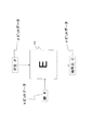
本発明の一実施例に係る非線形変換処理構成としてのnビット入出力S−boxの構成例を図13に示す。図13に示す構成は、4つのn/2ビット入出力の全単射S−box201〜204と、拡大体GF(2n/2)において定義される2×2MDS(Maximum Distance Separable)行列からなる線形変換処理部211から構成されるnビット入出力の非線形変換処理を実行する構成である。
FIG. 13 shows a configuration example of an n-bit input / output S-box as a nonlinear conversion processing configuration according to an embodiment of the present invention. The configuration shown in FIG. 13 includes four n / 2-bit input / output bijective S-
入力nビットは、上位n/2ビット、下位n/2ビットずつ、それぞれn/2ビット入出力の全単射S−box[S0]201,S−box[S1]202に入力され、それぞれのS−boxにおいて非線形変換処理がなされた後、拡大体GF(2n/2)において定義される2×2MDS行列からなる線形変換処理部211に入力されMDS行列に基づく線形変換処理がなされた後、線形変換結果のnビットの上位n/2ビット、下位n/2ビットずつ、それぞれn/2ビット入出力の全単射S−box[S2]203,S−box[S3]204に入力され、それぞれのS−boxにおいて非線形変換処理がなされて出力結果としてのnビットを得る構成となっている。
The input n bits are input to the bijective S-box [S 0 ] 201 and S-box [S 1 ] 202 of the n / 2-bit input / output respectively for the upper n / 2 bits and the lower n / 2 bits, After nonlinear conversion processing is performed in each S-box, the linear conversion processing based on the MDS matrix is input to the linear
図13に示す線形変換処理部211において適用されるMDS行列のように分岐数の高い拡散変換行列を利用すると、前段の小さなS−box[S0]201,S−box[S1]202の出力が後段の小さなS−box[S2]203,S−box[S3]204の入力にバランスよく配置されることが保証されるため、全体として特性の良い大きなS−boxが生成できる。また、線形変換処理部211において適用される拡散変換行列に相当するMDS行列の要素のサイズは小さなS−boxの入出力サイズ(n/2)によって一意に決まるため、大きなS−boxの入出力サイズ(n)が大きくなったとしても選択できる行列の空間は限られるため、容易にその行列の分岐数をチェックすることができる。
When a diffusion transformation matrix having a high branch number such as the MDS matrix applied in the linear
図13に示す構成における線形変換処理部211において適用される拡散変換行列としてのMDS行列の要素のサイズはn/2ビットであり、2×2の行列であるため、要素の数は4つとなり、全行列を調べたとしてもその数は、2n/2×4種程度であるため、容易に全行列を調べることが可能である。ただし、行列演算はGF(2)上で定義されるn次の既約多項式p(x)によって作られる拡大体GF(2n)上の行列演算とする。
The size of the element of the MDS matrix as the diffusion transformation matrix applied in the linear
この手法でS−boxを生成すると、簡易な代数表現が可能なのは、図13に示す構成中の入出力サイズn/2ビットの小さなS−box201〜204に限られると考えられるため、拡大体GF(2n)上での要素はランダムのように見える。よって、GF(2n)上で単純な代数的表現を行うことは難しいと考えることができる。また、拡大体上でのべき乗演算のように均一的な拡散はしないことが期待される。
When an S-box is generated by this method, it is considered that simple algebraic expression is possible only for small S-
さらに、行列を適切に選択すれば、簡易な演算と短いパスで構成することが可能なため、n−bitでランダムに生成されたS−boxや、従来の小さなS−boxを組み合わせて構成したS−boxよりもより実装効率は高いと言える。 Furthermore, since it is possible to configure with a simple operation and a short path if an appropriate matrix is selected, it is configured by combining an S-box randomly generated with n-bits and a conventional small S-box. It can be said that the mounting efficiency is higher than that of the S-box.
図13に示す構成を適用した具体的な8ビット入出力の非線形変換を実行するS−boxの構成例について、図14〜図17を参照して説明する。 A specific example of an S-box configuration that performs nonlinear conversion of 8-bit input / output to which the configuration shown in FIG. 13 is applied will be described with reference to FIGS. 14 to 17.
図14(a)、図15(a)に示す構成は同一であり、図13に示す構成を適用した具体的な8ビット入出力の非線形変換を実行するS−boxの一構成例としての8ビットS−box300の構成を示す図である。図14(b)は、図14(a)に示す8ビットS−box300の構成要素である4つの4ビット入出力S−box301〜304の変換テーブルを示している。このテーブルで用いている数値は16進数である。入力:x=0〜F(16進数)に対する各S−box301〜304の出力値を示すテーブルである。また、図15(c)には、図15(a)(=図14(a))に示す線形変換処理部311として分岐数の高い拡散変換、具体的には最適拡散変換[ODM]であるMDS行列(matrix)311を使用した具体例を示している。
The configurations shown in FIGS. 14A and 15A are the same, and 8 as a configuration example of an S-box that performs a specific 8-bit input / output nonlinear conversion to which the configuration shown in FIG. 13 is applied. FIG. 4 is a diagram showing a configuration of a bit S-
図14(a)に示す8ビット入出力の非線形変換を実行するS−boxの処理について説明する。まず、8ビットS−box300の入力であるx(8−bit)は1/2、つまり4−bitごとにx[0],x[1]に分割される。次にx[0]は4−bit入出力のS−box[S40]301へ入力され、x[1]は4−bit入出力のS−box[S41]302へそれぞれ入力され、各S−box301,302における非線形変換結果としての出力w[0],w[1]を得る。S−box[S40]301、S−box[S41]302は、ランダムに選択した4ビットS−boxであり、非線形変換は、図14(b)のテーブルに従った変換処理として実行される。
The S-box process for executing the 8-bit input / output nonlinear conversion shown in FIG. First, x (8-bit), which is an input of the 8-bit S-
なお、S−box[S40]301、S−box[S41]302は、最大差分確率が十分低いことや最大線形確率が十分低いことなどS−boxが満たすべきあらゆる性質を満たすようなS−boxである。また、これらのS−boxは4−bit入出力なので、このような性質を満たすS−boxを探索することが現実的に可能である。 Note that S-box [S4 0 ] 301 and S-box [S4 1 ] 302 are Ss that satisfy all properties that the S-box must satisfy, such as a sufficiently low maximum difference probability and a sufficiently low maximum linear probability. -Box. Further, since these S-boxes are 4-bit input / output, it is practically possible to search for S-boxes that satisfy such properties.
S−box[S40]301、S−box[S41]302の出力w[0],w[1]は、最適拡散変換[ODM]であるMDS行列(matrix)による線形変換を実行する線形変換処理部311に入力され、MDS行列(matrix)による線形変換結果として、z[0],z[1]を出力する。線形変換処理部311では、GF(2)上で定義される4次の既約多項式:p(x)=x4+x+1によって作られる拡大体GF(24)上の行列演算による線形変換が実行され、z[0],z[1]を出力する。線形変換処理部311としてのMDS行列(matrix)は、GF(2)上の4次の既約多項式で定義される拡大体GF(24)上の元を要素として持つ2×2の4要素からなる行列に基づく線形変換処理を実行する。
The outputs w [0] and w [1] of the S-box [S4 0 ] 301 and S-box [S4 1 ] 302 are linear for executing linear transformation by an MDS matrix (matrix) which is an optimal diffusion transformation [ODM]. Z [0] and z [1] are output to the
行列演算の具体的処理を図15(c)に示す。図15(c)に示す2×2のMDS行列を適用した場合、入力w[0],w[1]に基づいて、出力z[0],z[1]は、以下のように算出される。
z[0]=w[0](XOR)w[1]×2
z[1]=w[0]×2(XOR)w[1]
Specific processing of the matrix operation is shown in FIG. When the 2 × 2 MDS matrix shown in FIG. 15C is applied, the outputs z [0] and z [1] are calculated as follows based on the inputs w [0] and w [1]. The
z [0] = w [0] (XOR) w [1] × 2
z [1] = w [0] × 2 (XOR) w [1]
最適拡散変換[ODM]であるMDS行列(matrix)による線形変換結果として得られた8ビットデータ中の上位4ビットz[0]は4−bit入出力のS−box[S42]303へ、下位4ビットz[1]は4−bit入出力のS−box[S43]304へそれぞれ入力され、これらの4ビットS−boxにおいて非線形変換が実行され、出力y[0],y[1]を得る。S−box[S42]303、S−box[S43]304は、S−box[S40]301、S−box[S41]302と同様,それぞれランダムに選択した特性のよい4ビットS−boxであり、図14(b)に示すテーブルに従ったデータ変換を実行する。最終的に、S−box[S42]303、S−box[S43]304の出力する4ビットデータy[0]とy[1]を結合した8ビットデータを、8ビット入出のS−box300の最終的な出力y(8−bit)とする。
The upper 4 bits z [0] in the 8-bit data obtained as a result of the linear transformation by the MDS matrix (matrix) which is the optimal diffusion transformation [ODM] is transferred to the 4-bit input / output S-box [S4 2 ] 303. The lower 4 bits z [1] are respectively input to 4-bit input / output S-box [S4 3 ] 304, and nonlinear conversion is performed on these 4-bit S-boxes, and outputs y [0], y [1 ] Is obtained. S-box [S4 2 ] 303 and S-box [S4 3 ] 304 are 4-bit S with good characteristics selected at random, similar to S-box [S4 0 ] 301 and S-box [S4 1 ] 302, respectively. -Box, which performs data conversion according to the table shown in FIG. Finally, 8-bit data obtained by combining 4-bit data y [0] and y [1] output from S-box [S4 2 ] 303 and S-box [S4 3 ] 304 is converted into 8-bit input / output S- The final output y (8-bit) of the
図16(a)に示す構成は、図14(a)に示す構成と同様、図13に示す構成を適用した具体的な8ビット入出力の非線形変換を実行する8ビットS−box320の一構成例であり、図16(b)は、図16(a)に示す8ビットS−box320の構成要素である4つの4ビット入出力S−box321〜324の変換テーブルを示している。このテーブルで用いている数値は16進数である。入力:x=0〜F(16進数)に対する各S−box321〜324の出力値を示すテーブルである。また、図17(c)には、図17(a)(=図16(a))に示す線形変換処理部331として最適拡散変換[ODM]であるMDS行列(matrix)331を用いた具体例を示している。
The configuration shown in FIG. 16A is a configuration of an 8-bit S-
図16、図17に示す構成例は、
4ビット入出力S−box321〜324が、図16(b)に示すテーブルに従った非線形変換を実行すること、
線形変換処理部331が、図17(c)に従った変換処理を行なうこと、
これらの処理が異なっている。
The configuration example shown in FIG. 16 and FIG.
The 4-bit input / output S-
The linear
These processes are different.
線形変換処理部331では、GF(2)上で定義される4次の既約多項式:p(x)=x4+x+1によって作られる拡大体GF(24)上の行列演算による線形変換が実行され、z[0],z[1]を出力する。線形変換処理部311としてのMDS行列(matrix)は、4次の既約多項式で定義される2の拡大体GF(24)上の元を要素として持つ2×2の4要素からなる行列に基づく線形変換処理を実行する。
The linear
行列演算の具体的処理を図17(c)に示す。図17(c)に示す2×2のMDS行列を適用した場合、入力w[0],w[1]に基づいて、出力z[0],z[1]は、以下のように算出される。
z[0]=w[0](XOR)w[1]
z[1]=w[0](XOR)w[1]×2
Specific processing of the matrix operation is shown in FIG. When the 2 × 2 MDS matrix shown in FIG. 17C is applied, the outputs z [0] and z [1] are calculated as follows based on the inputs w [0] and w [1]. The
z [0] = w [0] (XOR) w [1]
z [1] = w [0] (XOR) w [1] × 2
図14〜図17に示す例は、8ビット入出力方の非線形変換処理を実行するSボックスであり、いずれも線形変換処理部311,331において適用されるMDS行列の要素のサイズはn/2ビットであり、2×2の行列であるため、要素の数は4つとなり、全行列を調べたとしてもその数は、2n/2×4種程度であるため、容易に全行列を調べることが可能であり、前述したように、この手法でS−boxを生成すると、簡易な代数表現が可能なのは小さなS−boxに限られると考えられるため、拡大体GF(2n)上での要素はランダムのように見え、GF(2n)上で単純な代数的表現を行うことは難しいと考えることができる。また、拡大体上でのべき乗演算のように均一的な拡散はしない。また、入力から出力を得るためのパスには小さなS−boxが2つあるのみであり、行列を適切に選択すれば、簡易な演算と短いパスで構成することが可能なため、n−bitでランダムに生成されたS−boxや、従来の小さなS−boxを組み合わせて構成したS−boxよりもより実装効率は高くなる。
The example shown in FIGS. 14 to 17 is an S box that executes an 8-bit input / output nonlinear transformation process, and the size of the elements of the MDS matrix applied in the linear
図13〜図17に示した構成例では、入力nビットを2分割して上位n/2ビット、下位n/2ビットずつを、それぞれn/2ビット入出力のS−boxに入力する構成であり、また、線形変換処理部からの出力nビットの上位n/2ビット、下位n/2ビットずつ、それぞれn/2ビット入出力のS−box[S2]に入力して非線形変換処理結果を得る構成であるが、入力ビットを分割して入力する小さなS−boxの数は、2に限らず、この他の数でもよい。図18に、入力nビットを4分割してn/4ビットずつの非線形変換処理を行なう小さなn/4ビット入出力S−boxを利用したnビットS−box400の構成例を示す。
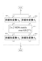
In the configuration examples shown in FIGS. 13 to 17, the input n bits are divided into two and the upper n / 2 bits and the lower n / 2 bits are input to the S / 2 boxes of the n / 2 bit input / output, respectively. Also, the higher-order n / 2 bits and lower-order n / 2 bits of the output n bits from the linear transformation processing unit are input to the S-box [S 2 ] of the n / 2-bit input / output, respectively, and the result of nonlinear transformation processing However, the number of small S-boxes that are input by dividing input bits is not limited to two, and other numbers may be used. FIG. 18 shows a configuration example of an n-bit S-
図18に示すnビットS−box400の構成は、8つのn/4ビット入出力の全単射S−box401〜408と、分岐数の高い拡散変換として最適拡散変換[ODM]である拡大体GF(2n/4)において定義される4×4MDS(Maximum Distance Separable)行列からなる線形変換処理部421から構成されるnビット入出力の非線形変換処理を実行する構成である。
The configuration of the n-bit S-
入力nビットは、n/4ビットずつ分割されて、それぞれn/4ビット入出力の全単射S−box[S0]401,S−box[S1]402,S−box[S2]403,S−box[S3]404に入力され、それぞれのS−boxにおいて非線形変換処理がなされた後、拡大体GF(2n/4)において定義される4×4MDS行列からなる線形変換処理部421に入力されMDS行列に基づく線形変換処理がなされた後、線形変換結果のnビットのn/4ビットずつが、それぞれn/4ビット入出力のS−box[S0]405,S−box[S1]406,S−box[S2]407,S−box[S3]408に入力され、それぞれのS−boxにおいて非線形変換処理がなされて出力結果としてのnビットを得る構成となっている。
The input n bits are divided by n / 4 bits, and the bijective S-box [S 0 ] 401, S-box [S 1 ] 402, and S-box [S 2 ] for n / 4-bit input / output, respectively. 403, S-box [S 3 ] 404, and after performing nonlinear transformation processing in each S-box, linear transformation processing consisting of 4 × 4 MDS matrix defined in the extension field GF (2 n / 4 ) After the linear conversion processing based on the MDS matrix is input to the
図18に示す線形変換処理部421において適用される拡散変換も最適拡散変換[ODM]であるMDS行列であり、前段の小さな4つのS−boxの出力が後段の小さなS−boxの入力にバランスよく配置されることが保証されるため、全体として特性の良い大きなS−boxが生成できる。
The diffusion transformation applied in the linear
上述した本発明に従った非線形変換処理を実行するSボックスによって構成されるデータ変換装置の構成について要約する。本発明のデータ変換装置は、以下のような構成を有することが特徴である。すなわち、
入力データを分割した分割データ各々の非線形変換処理を実行する複数の小型非線形変換部(小さなSボックス)からなる第1段非線形変換部と、
第1段非線形変換部を構成する複数の小型非線形変換部からの出力をすべて入力して線形変換を実行する線形変換部と、
線形変換部の出力データを分割した分割データ各々の非線形変換処理を実行する複数の小型非線形変換部(小さなSボックス)からなる第2段非線形変換部とを有し、
線形変換部は、入力データのビットサイズと同サイズの要素を持つ行列演算によるデータ変換を実行する構成であり、行列がm×m行列である場合、少なくともm以上の分岐数を有する高分岐数の行列を適用したデータ変換処理を実行する構成である。
The configuration of the data conversion apparatus configured by the S box that executes the nonlinear conversion processing according to the present invention described above will be summarized. The data converter of the present invention is characterized by having the following configuration. That is,
A first-stage non-linear conversion unit including a plurality of small non-linear conversion units (small S boxes) that execute non-linear conversion processing of each of divided data obtained by dividing input data;
A linear conversion unit that inputs all outputs from a plurality of small non-linear conversion units constituting the first-stage non-linear conversion unit and executes linear conversion;
A second-stage non-linear conversion unit composed of a plurality of small non-linear conversion units (small S boxes) that execute non-linear conversion processing of each of the divided data obtained by dividing the output data of the linear conversion unit,
The linear conversion unit is configured to perform data conversion by matrix operation having an element of the same size as the bit size of input data. When the matrix is an m × m matrix, the number of high branches having at least m or more branches This is a configuration for executing a data conversion process to which the above matrix is applied.
具体的には、入力データがnビットデータである場合、第1非線形変換部は、入力データであるnビットデータの分割データであるn/kビットを各々入力して非線形変換処理結果としてのn/kビットを出力するk個の小型非線形変換部から構成され、線形変換部は、k個の小型非線形変換部の出力する総計nビットのデータを入力して、高分岐数の行列を適用したデータ変換処理によりnビットの出力を生成する構成であり、第2非線形変換部は、線形変換部から出力されるnビットデータの分割データであるn/kビットを各々入力して非線形変換処理結果としてのn/kビットを出力するk個の小型非線形変換部を有する構成である。 Specifically, when the input data is n-bit data, the first nonlinear conversion unit inputs n / k bits that are divided data of the n-bit data that is the input data, and outputs n as the nonlinear conversion processing result. It is composed of k small non-linear conversion units that output k bits, and the linear conversion unit inputs a total of n bits of data output from the k small non-linear conversion units and applies a matrix with a high branch number. The n-bit output is generated by data conversion processing, and the second non-linear conversion unit inputs n / k bits, which are divided data of n-bit data output from the linear conversion unit, respectively, and results of non-linear conversion processing The configuration includes k small non-linear conversion units that output n / k bits.
ここで、線形変換部は、分岐数がm以上である拡散変換、例えば最適拡散変換ODM(Optimal Diffusion Mappings)を実行するMDS(Maximum Distance Separable)行列を適用したデータ変換処理を実行する構成であり、さらに、具体的には、入力データがnビットデータである場合、GF(2)上で定義されるn次の既約多項式p(x)によって定義される拡大体GF(2n)上の行列を適用したデータ変換処理を実行する構成である。 Here, the linear conversion unit is configured to execute a data conversion process using an MDS (Maximum Distance Separable) matrix that executes diffusion conversion having the number of branches of m or more, for example, optimal diffusion conversion ODM (Optimal Diffusion Mappings). Furthermore, more specifically, when the input data is n-bit data, the extension field GF (2 n ) defined by the n-th irreducible polynomial p (x) defined on GF (2) In this configuration, a data conversion process using a matrix is executed.
なお、本発明に係るデータ変換装置は、先に説明したような共通鍵ブロック暗号処理を実行する装置として具現化可能であり、例えば、
(ア)SPN(Substitution Permutation Network)構造、
(イ)Feistel構造、
(ウ)拡張Feistel構造、
これらの構造を適用した暗号処理を行なう装置における非線形変換部に適用可能である。なお、本発明の構成は、暗号処理以外にもハッシュ関数など、非線形変換を行う演算装置において適用可能である。
The data conversion device according to the present invention can be embodied as a device that executes the common key block cipher processing as described above, for example,
(A) SPN (Substitution Permutation Network) structure,
(A) Feistel structure,
(C) Extended Feistel structure,
The present invention can be applied to a non-linear conversion unit in an apparatus that performs cryptographic processing using these structures. Note that the configuration of the present invention can be applied to an arithmetic device that performs non-linear transformation such as a hash function in addition to cryptographic processing.
[4.暗号処理装置の構成例]
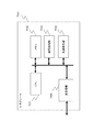
最後に、上述した実施例に従ったデータ変換処理を実行する装置例として暗号処理装置としてのICモジュール700の構成例を図19に示す。上述の処理は、例えばPC、ICカード、リーダライタ、その他、様々な情報処理装置において実行可能であり、図19に示すICモジュール700は、これら様々な機器に構成することが可能である。
[4. Configuration example of cryptographic processing device]
Finally, FIG. 19 shows a configuration example of an
図19に示すCPU(Central processing Unit)701は、暗号処理の開始や、終了、データの送受信の制御、各構成部間のデータ転送制御、その他の各種プログラムを実行するプロセッサである。メモリ702は、CPU701が実行するプログラム、あるいは演算パラメータなどの固定データを格納するROM(Read-Only-Memory)、CPU701の処理において実行されるプログラム、およびプログラム処理において適宜変化するパラメータの格納エリア、ワーク領域として使用されるRAM(Random Access Memory)等からなる。また、メモリ702は暗号処理に必要な鍵データや、暗号処理において適用する変換テーブル(置換表)や変換行列に適用するデータ等の格納領域として使用可能である。なおデータ格納領域は、耐タンパ構造を持つメモリとして構成されることが好ましい。
A CPU (Central processing Unit) 701 shown in FIG. 19 is a processor that executes the start and end of cryptographic processing, control of data transmission / reception, data transfer control between components, and other various programs. The
暗号処理部703は、例えば上述した各種の暗号処理構成、すなわち、
(ア)SPN(Substitution Permutation Network)構造、
(イ)Feistel構造、
(ウ)拡張Feistel構造、
これらの各構成のいずれかの構造を適用した共通鍵ブロック暗号処理アルゴリズムに従った暗号処理、復号処理、さらに、ハッシュ関数を適用した演算処理などを実行する。
The
(A) SPN (Substitution Permutation Network) structure,
(A) Feistel structure,
(C) Extended Feistel structure,
Encryption processing and decryption processing according to a common key block encryption processing algorithm to which any one of these structures is applied, and arithmetic processing using a hash function are executed.
また、暗号処理部703は、上述した実施例に対応した非線形変換処理を実行する構成、すなわち、nビット入出力S−boxの構成として、nより小さな入出力ビットの非線形変換を実行する小さなS−boxによる非線形変換を実行し、その結果を、MDS行列などの分岐数の高い拡散変換行列に入力して行列を適用した変換を実行し、その変換結果をさらに、nより小さな入出力ビットの非線形変換を実行する小さなS−boxを適用して非線形変換を実行させてnビットの非線形変換結果を得る非線形変換処理を実行する構成を持つ。
In addition, the
なお、ここでは、暗号処理手段を個別モジュールとした例を示したが、このような独立した暗号処理モジュールを設けず、例えば暗号処理プログラムをROMに格納し、CPU701がROM格納プログラムを読み出して実行するように構成してもよい。
Here, an example is shown in which the cryptographic processing means is an individual module, but such an independent cryptographic processing module is not provided, for example, a cryptographic processing program is stored in the ROM, and the
乱数発生器704は、暗号処理に必要となる鍵の生成などにおいて必要となる乱数の発生処理を実行する。
The
送受信部705は、外部とのデータ通信を実行するデータ通信処理部であり、例えばリーダライタ等、ICモジュールとのデータ通信を実行し、ICモジュール内で生成した暗号文の出力、あるいは外部のリーダライタ等の機器からのデータ入力などを実行する。
The transmission /
このICモジュール700は、上述した実施例に従った非線形変換処理部としてのS−boxを適用した処理、すなわち、図13〜図18を参照して説明した構成を持つS−boxを適用した非線形変換処理を実行する構成を持つ。
This
以上、特定の実施例を参照しながら、本発明について詳解してきた。しかしながら、本発明の要旨を逸脱しない範囲で当業者が該実施例の修正や代用を成し得ることは自明である。すなわち、例示という形態で本発明を開示してきたのであり、限定的に解釈されるべきではない。本発明の要旨を判断するためには、特許請求の範囲の欄を参酌すべきである。 The present invention has been described in detail above with reference to specific embodiments. However, it is obvious that those skilled in the art can make modifications and substitutions of the embodiments without departing from the gist of the present invention. In other words, the present invention has been disclosed in the form of exemplification, and should not be interpreted in a limited manner. In order to determine the gist of the present invention, the claims should be taken into consideration.
なお、明細書中において説明した一連の処理はハードウェア、またはソフトウェア、あるいは両者の複合構成によって実行することが可能である。ソフトウェアによる処理を実行する場合は、処理シーケンスを記録したプログラムを、専用のハードウェアに組み込まれたコンピュータ内のメモリにインストールして実行させるか、あるいは、各種処理が実行可能な汎用コンピュータにプログラムをインストールして実行させることが可能である。 The series of processes described in the specification can be executed by hardware, software, or a combined configuration of both. When executing processing by software, the program recording the processing sequence is installed in a memory in a computer incorporated in dedicated hardware and executed, or the program is executed on a general-purpose computer capable of executing various processing. It can be installed and run.
例えば、プログラムは記録媒体としてのハードディスクやROM(Read Only Memory)に予め記録しておくことができる。あるいは、プログラムはフレキシブルディスク、CD−ROM(Compact Disc Read Only Memory),MO(Magneto optical)ディスク,DVD(Digital Versatile Disc)、磁気ディスク、半導体メモリなどのリムーバブル記録媒体に、一時的あるいは永続的に格納(記録)しておくことができる。このようなリムーバブル記録媒体は、いわゆるパッケージソフトウエアとして提供することができる。 For example, the program can be recorded in advance on a hard disk or ROM (Read Only Memory) as a recording medium. Alternatively, the program is temporarily or permanently stored on a removable recording medium such as a flexible disk, a CD-ROM (Compact Disc Read Only Memory), an MO (Magneto optical) disk, a DVD (Digital Versatile Disc), a magnetic disk, or a semiconductor memory. It can be stored (recorded). Such a removable recording medium can be provided as so-called package software.
なお、プログラムは、上述したようなリムーバブル記録媒体からコンピュータにインストールする他、ダウンロードサイトから、コンピュータに無線転送したり、LAN(Local Area Network)、インターネットといったネットワークを介して、コンピュータに有線で転送し、コンピュータでは、そのようにして転送されてくるプログラムを受信し、内蔵するハードディスク等の記録媒体にインストールすることができる。 The program is installed on the computer from the removable recording medium as described above, or is wirelessly transferred from the download site to the computer, or is wired to the computer via a network such as a LAN (Local Area Network) or the Internet. The computer can receive the program transferred in this manner and install it on a recording medium such as a built-in hard disk.
なお、明細書に記載された各種の処理は、記載に従って時系列に実行されるのみならず、処理を実行する装置の処理能力あるいは必要に応じて並列的にあるいは個別に実行されてもよい。また、本明細書においてシステムとは、複数の装置の論理的集合構成であり、各構成の装置が同一筐体内にあるものには限らない。 Note that the various processes described in the specification are not only executed in time series according to the description, but may be executed in parallel or individually according to the processing capability of the apparatus that executes the processes or as necessary. Further, in this specification, the system is a logical set configuration of a plurality of devices, and the devices of each configuration are not limited to being in the same casing.
上述したように、本発明の一実施例の構成によれば、例えば、共通鍵ブロック暗号を適用した暗号処理などにおいて実行される非線形変換処理を、複数の小さなSボックス(S−box)による非線形変換を実行する第1段の非線形変換部と、第1段非線形変換部からの出力をすべて入力して線形変換を実行する線形変換部と、線形変換部の出力データを分割した分割データ各々の非線形変換処理を実行する複数の小型非線形変換部からなる第2段非線形変換部とを適用したデータ変換を行う構成とし、線形変換部では、最適拡散変換を行う行列を適用したデータ変換を実行する構成としたので、データの入力から出力に至るクリティカルパスを過大にすることなく、適切なデータ拡散を実現して、各種の暗号攻撃に対する耐性の強い安全性の高いデータ変換を実現することができる。 As described above, according to the configuration of the embodiment of the present invention, for example, the non-linear transformation process executed in the cipher process to which the common key block cipher is applied is performed by a non-linear process using a plurality of small S boxes (S-boxes). A first-stage non-linear conversion unit that performs conversion, a linear conversion unit that performs linear conversion by inputting all outputs from the first-stage non-linear conversion unit, and divided data obtained by dividing the output data of the linear conversion unit The data conversion is performed by applying a second-stage nonlinear conversion unit composed of a plurality of small nonlinear conversion units that perform nonlinear conversion processing, and the linear conversion unit performs data conversion using a matrix that performs optimal diffusion conversion. Because it is configured, it achieves appropriate data diffusion without overlying the critical path from data input to output, and is highly resistant to various cryptographic attacks It is possible to achieve high data conversion.
10 共通鍵ブロック暗号処理部E
11 鍵スケジューリング部
12 暗号処理部
20 ラウンド関数実行部
21 排他的論理和演算部
22 非線形変換処理部
23 線形変換処理部
30 F関数部
31 排他的論理和演算部
32 非線形変換処理部
33 線形変換処理部
34 排他的論理和演算部
41,42 F関数部
50 非線形変換処理部
51 Sボックス
101〜103 Sボックス(S−box)
111〜113 排他的論理和演算部
121〜124 Sボックス(S−box)
131 ビット演算部
141〜145 Sボックス(S−box)
151〜153 排他的論理和演算部
161〜163 Sボックス(S−box)
171,172 OR回路
200 Sボックス(S−box)
201〜204 Sボックス(S−box)
211 線形変換処理部
200 Sボックス(S−box)
301〜304 Sボックス(S−box)
311 線形変換処理部
320 Sボックス(S−box)
321〜324 Sボックス(S−box)
331 線形変換処理部
700 ICモジュール
701 CPU(Central processing Unit)
702 メモリ
703 暗号処理部
704 乱数発生器
705 送受信部
10 Common key block encryption processing section E
DESCRIPTION OF SYMBOLS 11
111-113 Exclusive OR operator 121-124 S box (S-box)
131-bit operation unit 141-145 S box (S-box)
151-153 Exclusive OR operator 161-163 S box (S-box)
171, 172 OR circuit 200 S box (S-box)
201-204 S box (S-box)
211 Linear transformation processing unit 200 S box (S-box)
301-304 S box (S-box)
311 linear transformation processing unit 320 S box (S-box)
321-324 S box (S-box)
331 Linear
702
Claims (8)
前記データ変換装置は、F関数を複数ラウンド繰り返し実行する構成を有し、
前記F関数の各ラウンドのラウンド鍵のビット数と同じビット数を有するように変換対象データを分割する第1データ分割部と、
前記第1データ分割部で分割された分割データに前記ラウンド鍵の鍵加算を実行する鍵加算部と、
前記鍵加算部で鍵加算された前記分割データを入力して非線形変換処理を実行するF関数内非線形変換部と、
前記F関数内非線形変換部の出力に対する線形変換処理を実行するF関数内線形変換部を有し、
前記F関数内非線形変換部は、
前記鍵加算部で鍵加算された前記分割データをさらに分割する第2データ分割部と、
前記第2データ分割部で分割された分割データ各々の非線形処理を実行する複数の小型非線形変換部からなる第1段サブ非線形変換部と、
前記第1段サブ非線形変換部を構成する複数の小型非線形変換部からの出力をすべて入力して線形変換を実行するサブ線形変換部と、
前記サブ線形変換部の出力データを分割する第3データ分割部と、
前記第3データ分割部で分割した分割データ各々の非線形変換処理を前記サブ線形変換部による線形変換の直後に実行する複数の小型非線形変換部からなる第2段サブ非線形変換部とを有し、
前記サブ線形変換部は、
前記第1段サブ非線形変換部の出力データのビットサイズと同サイズの要素を持つ行列演算によるデータ変換を実行する構成であり、行列がm×m行列である場合、少なくともm以上の分岐数を有する高分岐数の行列を適用したデータ変換処理を実行する構成であることを特徴とするデータ変換装置。 A data converter,
The data conversion device has a configuration in which an F function is repeatedly executed a plurality of rounds,
A first data dividing unit that divides data to be converted so as to have the same number of bits as the number of round keys of each round of the F function;
A key addition unit that performs key addition of the round key to the divided data divided by the first data division unit;
A non-linear transformation unit in F function that inputs the divided data key-added by the key addition unit and executes nonlinear transformation processing;
An F-function linear transformation unit that performs linear transformation processing on the output of the F-function nonlinear transformation unit;
The F function non-linear transformation unit includes:
A second data dividing unit that further divides the divided data subjected to key addition by the key adding unit;
A first-stage sub- nonlinear conversion unit including a plurality of small non-linear conversion units that execute non-linear processing of each of the divided data divided by the second data division unit ;
A sub linear conversion unit that performs linear conversion by inputting all outputs from a plurality of small non-linear conversion units constituting the first stage sub non - linear conversion unit;
A third data dividing unit for dividing the output data of the sub linear conversion unit ;
A second-stage sub- nonlinear conversion unit comprising a plurality of small non-linear conversion units that execute non-linear conversion processing of each of the divided data divided by the third data dividing unit immediately after linear conversion by the sub-linear conversion unit ;
The sub- linear conversion unit includes:
The data conversion is performed by a matrix operation having an element having the same size as the bit size of the output data of the first-stage sub-nonlinear conversion unit , and when the matrix is an m × m matrix, the number of branches is at least m or more. A data conversion apparatus characterized by being configured to execute data conversion processing to which a matrix having a high branching number is applied.
前記第1段サブ非線形変換部は、入力データであるnビットデータの分割データであるn/kビットを各々入力して非線形変換処理結果としてのn/kビットを出力するk個の小型非線形変換部から構成され、
前記サブ線形変換部は、前記k個の小型非線形変換部の出力する総計nビットのデータを入力して、高分岐数の行列を適用したデータ変換処理によりnビットの出力を生成する構成であり、
前記第2段サブ非線形変換部は、前記サブ線形変換部から出力されるnビットデータの分割データであるn/kビットを各々入力して非線形変換処理結果としてのn/kビットを出力するk個の小型非線形変換部を有する構成であることを特徴とする請求項1に記載のデータ変換装置。 When input data to the first stage sub-nonlinear conversion unit is n-bit data,
The first stage sub- nonlinear conversion unit inputs n / k bits, which are divided data of n-bit data, which is input data, and outputs n / k bits as a result of nonlinear conversion processing, and outputs k small non-linear conversions Consisting of parts
The sub- linear conversion unit is configured to input a total of n-bit data output from the k small non-linear conversion units and generate an n-bit output by data conversion processing using a matrix having a high branching number. ,
The second- stage sub- nonlinear conversion unit inputs n / k bits that are divided data of n-bit data output from the sub- linear conversion unit, and outputs n / k bits as a result of nonlinear conversion processing. The data conversion apparatus according to claim 1, wherein the data conversion apparatus has a single small nonlinear conversion unit.
前記入力データがnビットデータである場合、
GF(2)上で定義されるn次の既約多項式p(x)によって定義される拡大体GF(2n)上の行列を適用したデータ変換処理を実行する構成であることを特徴とする請求項1に記載のデータ変換装置。 The sub- linear conversion unit includes:
When the input data is n-bit data,
The present invention is characterized in that a data conversion process is performed by applying a matrix on an extension field GF (2 n ) defined by an n-th irreducible polynomial p (x) defined on GF (2). The data conversion apparatus according to claim 1.
非線形変換処理を伴う暗号処理を実行する構成であることを特徴とする請求項1〜4いずれかに記載のデータ変換装置。 The data converter is
The data conversion apparatus according to claim 1 , wherein the data conversion apparatus is configured to execute an encryption process involving a non-linear conversion process.
前記データ変換装置は、ラウンド関数を複数ラウンド繰り返し実行する構成を有し、
第1データ分割部において、前記ラウンド関数の各ラウンドのラウンド鍵のビット数と同じビット数を有するように変換対象データを分割する第1データ分割ステップと、
鍵加算部において、前記第1データ分割部で分割されたデータに前記ラウンド鍵の鍵加算を実行する鍵加算ステップと、
F関数内非線形変換部において、前記鍵加算部で鍵加算された前記分割データを入力して非線形変換処理を実行するF関数内非線形変換ステップと、
F関数内線形変換部において、前記F関数内非線形変換部の出力に対する線形変換処理を実行するF関数内線形変換ステップを実行し、
前記F関数内非線形変換ステップは、
第2データ分割部において、前記鍵加算部で鍵加算された前記分割データをさらに分割する第2データ分割ステップと、
第1段サブ非線形変換部において、前記第2データ分割部で分割された分割データ各々の非線形変換処理を実行する第1段サブ非線形変換ステップと、
サブ線形変換部において、前記第1段サブ非線形変換部を構成する複数の小型非線形変換部からの出力をすべて入力して線形変換を実行するサブ線形変換ステップと、
第3データ分割部において、前記サブ線形変換部の出力データを分割する第3データ分割ステップと、
第2段サブ非線形変換部において、複数の小型非線形変換部を適用して、前記第3データ分割部で分割した分割データ各々の非線形変換処理を前記サブ線形変換部の線形変換直後に実行する第2段サブ非線形変換ステップとを有し、
前記サブ線形変換ステップは、
前記第1段サブ非線形変換部の出力データのビットサイズと同サイズの要素を持つ行列演算によるデータ変換を実行する構成であり、行列がm×m行列である場合、少なくともm以上の分岐数を有する高分岐数の行列を適用したデータ変換処理を実行するステップであることを特徴とするデータ変換方法。 A data conversion method executed in the data conversion device,
The data conversion device has a configuration that repeatedly executes a round function a plurality of rounds,
A first data dividing step of dividing the data to be converted so as to have the same number of bits as the number of round keys of each round of the round function in the first data dividing unit;
In a key addition unit, a key addition step of performing key addition of the round key to the data divided by the first data division unit;
In an F-function non-linear transformation unit, an intra-F-function non-linear transformation step of inputting the divided data subjected to key addition by the key addition unit and executing non-linear transformation processing;
In the F-function linear transformation unit, an F-function linear transformation step is performed to perform a linear transformation process on the output of the F-function nonlinear transformation unit;
The F-function nonlinear transformation step includes:
A second data dividing step of further dividing the divided data key-added by the key adding unit in the second data dividing unit;
In the first stage sub nonlinear transformation unit, and a first-stage sub-nonlinear transformation step of performing a non-linear transformation processing of divided data units divided by the second data division unit,
In the sub- linear conversion unit, a sub- linear conversion step for performing linear conversion by inputting all outputs from a plurality of small non-linear conversion units constituting the first stage sub- non-linear conversion unit;
In a third data dividing unit, a third data dividing step of dividing the output data of the sub linear conversion unit ;
In the second-stage sub- nonlinear conversion unit, a plurality of small non-linear conversion units are applied to execute non-linear conversion processing of each of the divided data divided by the third data division unit immediately after the linear conversion of the sub-linear conversion unit . A two-stage sub- nonlinear transformation step,
The sub- linear transformation step includes
The data conversion is performed by a matrix operation having an element having the same size as the bit size of the output data of the first-stage sub-nonlinear conversion unit , and when the matrix is an m × m matrix, the number of branches is at least m or more. A data conversion method comprising a step of executing data conversion processing to which a matrix having a high branching number is applied.
前記データ変換装置は、ラウンド関数を複数ラウンド繰り返し実行する構成を有し、
第1データ分割部において、前記ラウンド関数の各ラウンドのラウンド鍵のビット数と同じビット数を有するように変換対象データを分割させる第1データ分割ステップと、
鍵加算部において、前記第1データ分割部で分割されたデータに前記ラウンド鍵の鍵加算を実行させる鍵加算ステップと、
F関数内非線形変換部において、前記鍵加算部で鍵加算された前記分割データを入力して非線形変換処理を実行させるF関数内非線形変換ステップと、
F関数内線形変換部において、前記F関数内非線形変換部の出力に対する線形変換処理を実行させるF関数内線形変換ステップを実行し、
前記F関数内非線形変換ステップにおいては、
第2データ分割部において、前記鍵加算部で鍵加算された前記分割データをさらに分割させる第2データ分割ステップと、
第1段サブ非線形変換部において、前記第2データ分割部で分割された分割データ各々の非線形変換処理を実行させる第1段サブ非線形変換ステップと、
サブ線形変換部において、前記第1段サブ非線形変換部を構成する複数の小型非線形変換部からの出力をすべて入力して線形変換を実行させるサブ線形変換ステップと、
第3データ分割部において、前記サブ線形変換部の出力データを分割させる第3データ分割ステップと、
第2段サブ非線形変換部において、複数の小型非線形変換部を適用して、前記第3データ分割部で分割した分割データ各々の非線形変換処理を前記サブ線形変換部の線形変換直後に実行させる第2段サブ非線形変換ステップとを有し、
前記サブ線形変換ステップは、
前記第1段サブ非線形変換部の出力データのビットサイズと同サイズの要素を持つ行列演算によるデータ変換を実行する構成であり、行列がm×m行列である場合、少なくともm以上の分岐数を有する高分岐数の行列を適用したデータ変換処理を実行させるステップであることを特徴とするコンピュータ・プログラム。 A computer program for executing data conversion processing in a data conversion device,
The data conversion device has a configuration that repeatedly executes a round function a plurality of rounds,
A first data dividing unit for dividing the conversion target data so as to have the same number of bits as the number of bits of the round key of each round of the round function in the first data dividing unit;
In a key addition unit, a key addition step for performing key addition of the round key to the data divided by the first data division unit;
In an F-function non-linear transformation unit, an intra-F-function non-linear transformation step for executing the non-linear transformation process by inputting the divided data key-added by the key addition unit;
In the F-function linear transformation unit, an F-function linear transformation step for executing a linear transformation process on the output of the F-function nonlinear transformation unit;
In the F-function nonlinear transformation step,
A second data dividing unit for further dividing the divided data key-added by the key adding unit in the second data dividing unit;
A first-stage sub- nonlinear conversion unit, wherein a first-stage sub- nonlinear conversion step of executing a non-linear conversion process on each of the divided data divided by the second data dividing unit ;
In the sub- linear conversion unit, a sub- linear conversion step for performing linear conversion by inputting all outputs from a plurality of small non-linear conversion units constituting the first stage sub- non-linear conversion unit;
In a third data dividing unit, a third data dividing step for dividing the output data of the sub linear conversion unit ;
In the second-stage sub- nonlinear conversion unit, a plurality of small non-linear conversion units are applied, and a non-linear conversion process for each of the divided data divided by the third data division unit is executed immediately after the linear conversion of the sub-linear conversion unit . A two-stage sub- nonlinear transformation step,
The sub- linear transformation step includes
The data conversion is performed by a matrix operation having an element having the same size as the bit size of the output data of the first-stage sub-nonlinear conversion unit , and when the matrix is an m × m matrix, the number of branches is at least m or more. A computer program characterized in that it is a step of executing a data conversion process to which a matrix having a high branching number is applied.
Priority Applications (1)
| Application Number | Priority Date | Filing Date | Title |
|---|---|---|---|
| JP2013249046A JP5772934B2 (en) | 2013-12-02 | 2013-12-02 | Data conversion apparatus, data conversion method, and computer program |
Applications Claiming Priority (1)
| Application Number | Priority Date | Filing Date | Title |
|---|---|---|---|
| JP2013249046A JP5772934B2 (en) | 2013-12-02 | 2013-12-02 | Data conversion apparatus, data conversion method, and computer program |
Related Parent Applications (1)
| Application Number | Title | Priority Date | Filing Date |
|---|---|---|---|
| JP2012102624A Division JP5680016B2 (en) | 2012-04-27 | 2012-04-27 | Decoding processing apparatus, information processing apparatus, decoding processing method, and computer program |
Publications (2)
| Publication Number | Publication Date |
|---|---|
| JP2014041389A JP2014041389A (en) | 2014-03-06 |
| JP5772934B2 true JP5772934B2 (en) | 2015-09-02 |
Family
ID=50393627
Family Applications (1)
| Application Number | Title | Priority Date | Filing Date |
|---|---|---|---|
| JP2013249046A Expired - Fee Related JP5772934B2 (en) | 2013-12-02 | 2013-12-02 | Data conversion apparatus, data conversion method, and computer program |
Country Status (1)
| Country | Link |
|---|---|
| JP (1) | JP5772934B2 (en) |
Families Citing this family (1)
| Publication number | Priority date | Publication date | Assignee | Title |
|---|---|---|---|---|
| JP7296609B2 (en) * | 2017-11-14 | 2023-06-23 | 地方独立行政法人東京都立産業技術研究センター | DIGITAL PROCESSING DEVICE, METHOD AND PROGRAM FOR MANUFACTURING DIGITAL PROCESSING DEVICE |
Family Cites Families (5)
| Publication number | Priority date | Publication date | Assignee | Title |
|---|---|---|---|---|
| JP2927079B2 (en) * | 1991-10-02 | 1999-07-28 | 松下電器産業株式会社 | Data encryption method and data encryption device |
| JP3499810B2 (en) * | 2000-03-06 | 2004-02-23 | 株式会社東芝 | ENCRYPTION DEVICE, ENCRYPTION METHOD, COMPUTER-READABLE RECORDING MEDIUM CONTAINING PROGRAM FOR FUNCTIONING COMPUTER AS ENCRYPTION DEVICE, AND COMPUTER READING RECORDING PROGRAM FOR FUNCTIONING COMPUTER AS DECRYPTION DEVICE, DECRYPTION METHOD, AND DECRYPTION DEVICE Possible recording media |
| CN100557663C (en) * | 2000-03-09 | 2009-11-04 | 三菱电机株式会社 | Data conversion device and data conversion method |
| EP1480371A1 (en) * | 2003-05-23 | 2004-11-24 | Mediacrypt AG | Device and method for encrypting and decrypting a block of data |
| JP4561252B2 (en) * | 2004-09-03 | 2010-10-13 | ソニー株式会社 | Cryptographic processing apparatus, cryptographic processing method, and computer program |
-
2013
- 2013-12-02 JP JP2013249046A patent/JP5772934B2/en not_active Expired - Fee Related
Also Published As
| Publication number | Publication date |
|---|---|
| JP2014041389A (en) | 2014-03-06 |
Similar Documents
| Publication | Publication Date | Title |
|---|---|---|
| CN102594546B (en) | Message processing device | |
| CN101512619B (en) | Encryption processing device and encryption processing method | |
| US9363074B2 (en) | Encryption processing apparatus, encryption processing method, and computer program | |
| CN101512620B (en) | Encryption processing apparatus and encryption processing method | |
| US8737603B2 (en) | Cryptographic processing apparatus, cryptographic processing method, and computer program | |
| US8396210B2 (en) | Cryptographic processing apparatus and cryptographic processing method, and computer program | |
| JP5682527B2 (en) | Cryptographic processing apparatus, cryptographic processing method, and program | |
| JP5680016B2 (en) | Decoding processing apparatus, information processing apparatus, decoding processing method, and computer program | |
| JP5772934B2 (en) | Data conversion apparatus, data conversion method, and computer program | |
| JP5338945B2 (en) | Decoding processing apparatus, information processing apparatus, decoding processing method, and computer program | |
| HK1138098B (en) | Encryption device, encryption method, and computer program |
Legal Events
| Date | Code | Title | Description |
|---|---|---|---|
| A621 | Written request for application examination |
Free format text: JAPANESE INTERMEDIATE CODE: A621 Effective date: 20131202 |
|
| A131 | Notification of reasons for refusal |
Free format text: JAPANESE INTERMEDIATE CODE: A131 Effective date: 20140909 |
|
| A521 | Request for written amendment filed |
Free format text: JAPANESE INTERMEDIATE CODE: A523 Effective date: 20141104 |
|
| TRDD | Decision of grant or rejection written | ||
| A01 | Written decision to grant a patent or to grant a registration (utility model) |
Free format text: JAPANESE INTERMEDIATE CODE: A01 Effective date: 20150602 |
|
| A61 | First payment of annual fees (during grant procedure) |
Free format text: JAPANESE INTERMEDIATE CODE: A61 Effective date: 20150615 |
|
| R151 | Written notification of patent or utility model registration |
Ref document number: 5772934 Country of ref document: JP Free format text: JAPANESE INTERMEDIATE CODE: R151 |
|
| R250 | Receipt of annual fees |
Free format text: JAPANESE INTERMEDIATE CODE: R250 |
|
| R250 | Receipt of annual fees |
Free format text: JAPANESE INTERMEDIATE CODE: R250 |
|
| R250 | Receipt of annual fees |
Free format text: JAPANESE INTERMEDIATE CODE: R250 |
|
| LAPS | Cancellation because of no payment of annual fees |