JP5771696B2 - Dual feedback vacuum fluidics for flow particle analyzers - Google Patents
Dual feedback vacuum fluidics for flow particle analyzers Download PDFInfo
- Publication number
- JP5771696B2 JP5771696B2 JP2013536693A JP2013536693A JP5771696B2 JP 5771696 B2 JP5771696 B2 JP 5771696B2 JP 2013536693 A JP2013536693 A JP 2013536693A JP 2013536693 A JP2013536693 A JP 2013536693A JP 5771696 B2 JP5771696 B2 JP 5771696B2
- Authority
- JP
- Japan
- Prior art keywords
- fluid
- flow
- sample
- resistance
- sheath
- Prior art date
- Legal status (The legal status is an assumption and is not a legal conclusion. Google has not performed a legal analysis and makes no representation as to the accuracy of the status listed.)
- Active
Links
- 239000002245 particle Substances 0.000 title claims description 52
- 230000009977 dual effect Effects 0.000 title 1
- 239000012530 fluid Substances 0.000 claims description 393
- 230000004044 response Effects 0.000 claims description 7
- 239000000463 material Substances 0.000 claims description 4
- 238000003825 pressing Methods 0.000 claims 3
- 230000011218 segmentation Effects 0.000 claims 1
- 210000004027 cell Anatomy 0.000 description 81
- 230000003068 static effect Effects 0.000 description 34
- 230000005284 excitation Effects 0.000 description 23
- 238000001514 detection method Methods 0.000 description 19
- 238000004458 analytical method Methods 0.000 description 14
- 238000010586 diagram Methods 0.000 description 11
- 230000008859 change Effects 0.000 description 7
- 238000011835 investigation Methods 0.000 description 6
- 238000005259 measurement Methods 0.000 description 6
- 239000002699 waste material Substances 0.000 description 6
- 238000013461 design Methods 0.000 description 5
- 230000002829 reductive effect Effects 0.000 description 5
- 230000008878 coupling Effects 0.000 description 4
- 238000010168 coupling process Methods 0.000 description 4
- 238000005859 coupling reaction Methods 0.000 description 4
- 239000007788 liquid Substances 0.000 description 4
- 230000003287 optical effect Effects 0.000 description 4
- 238000000034 method Methods 0.000 description 3
- 239000004033 plastic Substances 0.000 description 3
- 230000009467 reduction Effects 0.000 description 3
- 238000012360 testing method Methods 0.000 description 3
- 238000004164 analytical calibration Methods 0.000 description 2
- 238000000149 argon plasma sintering Methods 0.000 description 2
- 239000000470 constituent Substances 0.000 description 2
- 230000000694 effects Effects 0.000 description 2
- 238000000684 flow cytometry Methods 0.000 description 2
- 239000007850 fluorescent dye Substances 0.000 description 2
- 239000000203 mixture Substances 0.000 description 2
- 230000002572 peristaltic effect Effects 0.000 description 2
- 230000010349 pulsation Effects 0.000 description 2
- 239000000725 suspension Substances 0.000 description 2
- 230000007704 transition Effects 0.000 description 2
- 238000011144 upstream manufacturing Methods 0.000 description 2
- 229910000831 Steel Inorganic materials 0.000 description 1
- 230000001133 acceleration Effects 0.000 description 1
- 238000009825 accumulation Methods 0.000 description 1
- 230000002411 adverse Effects 0.000 description 1
- 230000002238 attenuated effect Effects 0.000 description 1
- 230000008901 benefit Effects 0.000 description 1
- 239000008280 blood Substances 0.000 description 1
- 210000004369 blood Anatomy 0.000 description 1
- 210000003850 cellular structure Anatomy 0.000 description 1
- 238000004140 cleaning Methods 0.000 description 1
- 239000000975 dye Substances 0.000 description 1
- 230000008030 elimination Effects 0.000 description 1
- 238000003379 elimination reaction Methods 0.000 description 1
- 239000011521 glass Substances 0.000 description 1
- 238000002372 labelling Methods 0.000 description 1
- 230000007246 mechanism Effects 0.000 description 1
- 238000012544 monitoring process Methods 0.000 description 1
- 238000011192 particle characterization Methods 0.000 description 1
- 230000000284 resting effect Effects 0.000 description 1
- 238000000926 separation method Methods 0.000 description 1
- 239000010959 steel Substances 0.000 description 1
- 239000012780 transparent material Substances 0.000 description 1
- 238000013022 venting Methods 0.000 description 1
Images


Classifications
-
- G—PHYSICS
- G01—MEASURING; TESTING
- G01N—INVESTIGATING OR ANALYSING MATERIALS BY DETERMINING THEIR CHEMICAL OR PHYSICAL PROPERTIES
- G01N15/00—Investigating characteristics of particles; Investigating permeability, pore-volume, or surface-area of porous materials
- G01N15/10—Investigating individual particles
- G01N15/14—Electro-optical investigation, e.g. flow cytometers
- G01N15/1404—Fluid conditioning in flow cytometers, e.g. flow cells; Supply; Control of flow
-
- G01N15/1409—
-
- Y—GENERAL TAGGING OF NEW TECHNOLOGICAL DEVELOPMENTS; GENERAL TAGGING OF CROSS-SECTIONAL TECHNOLOGIES SPANNING OVER SEVERAL SECTIONS OF THE IPC; TECHNICAL SUBJECTS COVERED BY FORMER USPC CROSS-REFERENCE ART COLLECTIONS [XRACs] AND DIGESTS
- Y10—TECHNICAL SUBJECTS COVERED BY FORMER USPC
- Y10T—TECHNICAL SUBJECTS COVERED BY FORMER US CLASSIFICATION
- Y10T137/00—Fluid handling
- Y10T137/0318—Processes
- Y10T137/0324—With control of flow by a condition or characteristic of a fluid
- Y10T137/0379—By fluid pressure
Description
本発明は、流体中の粒子の分析のための機器およびその使用方法に関する。 The present invention relates to an instrument for the analysis of particles in a fluid and a method of using the same.
フローサイトメーターの如きフロー式粒子分析器はよく知られた分析器具であり、光散乱および蛍光の如き光学的パラメーターに基づき、またはインピーダンスのような電気的特性によって、粒子の特性評価を可能にする。フローサイトメーターにおいて、例えばフルイド・サスペンション法での分子や数珠状につながった分析物または個々の細胞の如き粒子は、一般的には1つ以上のレーザーからの励起光にこれらの粒子がさらされる検出領域を通過し、この粒子の光散乱および蛍光の特性が測定される。粒子または一般的にその構成成分は、検出を容易にするために蛍光染料で標識付けされ、スペクトル的に個別の蛍光染料を用いて異なる粒子や構成成分を標識付けすることにより、極めて多数の異なる粒子や構成成分を同時に検出することができる。一般的に、検出は、検出されるべき個々の染料のそれぞれに対応する極めて多数の光検出器を用いて行われる。フローサイトメーターおよび走査型サイトメーターの両方は、例えばBD Biosciences(カリフォルニア州 San Jose)から商業的に入手可能である。フローサイトメーターの説明は、Shapiro, 2003, Practical Flow Cytometry, 第4版(ニュージャージー州 Hoboken の John Wiley and Son Inc.)に与えられており、ここで引用された文献のすべては、参照することによってここに組み入れられる。 Flow particle analyzers such as flow cytometers are well-known analytical instruments that allow particle characterization based on optical parameters such as light scattering and fluorescence, or by electrical properties such as impedance. . In a flow cytometer, particles such as molecules in a fluid suspension method, beaded analytes or individual cells are typically exposed to excitation light from one or more lasers. Passing through the detection region, the light scattering and fluorescence properties of the particles are measured. The particles, or generally their constituents, are labeled with fluorescent dyes to facilitate detection and a very large number of different by labeling different particles or constituents with spectrally distinct fluorescent dyes Particles and components can be detected simultaneously. In general, detection is performed using a very large number of photodetectors corresponding to each individual dye to be detected. Both flow cytometers and scanning cytometers are commercially available from, for example, BD Biosciences (San Jose, Calif.). An explanation of flow cytometers is given in Shapiro, 2003, Practical Flow Cytometry, 4th edition (John Wiley and Son Inc., Hoboken, NJ), and all references cited herein are incorporated by reference. Is incorporated here.
典型的なフローサイトメーターにおいて、粒子を含有する試料流体は、試料流体と同軸の環状流を形成してそのまま検出領域を通過する粒子なしシース流体に囲まれており、これによって粒子なしシース流体により囲まれた流体の流れの中央に水力学的に集束した粒子を含有する試料流体の流れを作り出す。試料流体は検出領域を通るすべての流体の流れのほんの一部のみを形成するため、試料流体に対するシース流体の割合は一般的に高い。 In a typical flow cytometer, a sample fluid containing particles is surrounded by a particleless sheath fluid that forms a coaxial annular flow with the sample fluid and passes directly through the detection region, thereby allowing the particleless sheath fluid to A sample fluid stream is created that contains hydrodynamically focused particles in the middle of the enclosed fluid stream. The ratio of sheath fluid to sample fluid is generally high because the sample fluid forms only a fraction of all fluid flow through the detection region.
一般的に、フローサイトメーターシステムは圧力駆動流体工学を用いて構築されており、雰囲気圧よりも大きな圧力により試料流体およびシース流体が検出領域を含む流動セルに供給される。圧力駆動流体工学システムの流動セルを通る流量の変更は、流動セルへと送り込まれる試料管および/またはシース流体リザーバー内の圧力を変更することによって達成される。流動セルを通って流れるシース流体に対する試料流体の割合は、試料管およびシース流体リザーバー内の圧力レベルと、試料流体およびシース流体の通路抵抗の割合との両方によって支配される。 Generally, a flow cytometer system is constructed using pressure-driven fluid engineering, and a sample fluid and a sheath fluid are supplied to a flow cell including a detection region by a pressure larger than an atmospheric pressure. Changing the flow rate through the flow cell of the pressure-driven fluidics system is accomplished by changing the pressure in the sample tube and / or sheath fluid reservoir that is fed into the flow cell. The ratio of sample fluid to sheath fluid flowing through the flow cell is governed by both the pressure level in the sample tube and sheath fluid reservoir and the ratio of passage resistance of the sample fluid and sheath fluid.
代わりに、フローサイトメーターシステムは真空駆動流体工学を用いて構築されており、真空ポンプが流動セルの下流を真空引きすると共に試料流体およびシース流体が雰囲気圧に保持される。真空駆動流体工学システムの流動セルを通る流量の変更は、真空ポンプによって得られる真空状態を変更することによって達成され、流動セルを通って流れるシース流体に対する試料流体の割合は、試料流体およびシース流体の通路抵抗の割合によって支配される。 Instead, the flow cytometer system is constructed using vacuum driven fluidics, where the vacuum pump evacuates downstream of the flow cell and the sample fluid and sheath fluid are held at ambient pressure. Changing the flow rate through the flow cell of the vacuum driven fluidics system is accomplished by changing the vacuum conditions obtained by the vacuum pump, and the ratio of sample fluid to sheath fluid flowing through the flow cell is determined by the sample fluid and sheath fluid. Is governed by the rate of passage resistance.
一般に、圧力駆動流体工学システムの設計は、システムの高い圧力レベルに耐える配管や結合部および封止材を含む部品を必要とするため、真空駆動流体工学システムの設計よりも複雑である。これに対し、真空駆動フローサイトメトリーシステムにおいて、試料管およびシース流体供給リザーバーに対する流体結合の設計は、これが加圧可能な配管や結合部および封止材の使用を必要としないので、著しく単純化される。加圧試料管の排除は、自動チューブリフターおよびロボット試料ローダーの如き補助装置の設計をさらに容易にする。 In general, the design of a pressure-driven fluidics system is more complicated than the design of a vacuum-driven fluidics system because it requires parts that include piping, joints and seals that can withstand the high pressure levels of the system. In contrast, in a vacuum-driven flow cytometry system, the fluid coupling design for the sample tube and sheath fluid supply reservoir is significantly simplified as it does not require the use of pressurizable tubing, couplings and seals. Is done. The elimination of pressurized sample tubes further facilitates the design of auxiliary devices such as automatic tube lifters and robotic sample loaders.
参照することによってここに組み入れられる特許文献1は、フローサイトメーターにて用いるための真空制御システムを記述する。このシステムは、開いた供給リザーバーからセル分析が行われる流動セルを介してシース流体を引き出し、流動セルの排液を開いた廃液リザーバーに排出する真空ポンプを含む。供給リザーバーから流動セルへと通じる導管を介して圧力低下が作り出され、この導管はまた、開いた試料容器から流動セルを通過する粒子(例えば細胞)懸濁液からなる試料をも吸引する。このシステムの流量は、流動セルの出口での真空レベルを監視することによって調整される。真空センサーに結合された制御回路は、真空ポンプモーターに加えられた電力を調整し、流動セルの出口でのあらかじめ設定された真空レベルを維持する。 U.S. Patent No. 6,053,075, incorporated herein by reference, describes a vacuum control system for use in a flow cytometer. The system includes a vacuum pump that draws sheath fluid from an open supply reservoir through a flow cell in which cell analysis is performed and discharges the flow cell drainage into an open waste reservoir. A pressure drop is created through a conduit leading from the supply reservoir to the flow cell, which also draws a sample consisting of a suspension of particles (eg, cells) passing through the flow cell from an open sample container. The flow rate of this system is adjusted by monitoring the vacuum level at the outlet of the flow cell. A control circuit coupled to the vacuum sensor regulates the power applied to the vacuum pump motor and maintains a preset vacuum level at the outlet of the flow cell.
本発明は、試料流体およびシース流体の如き2つ以上の流体供給源がフローサイトメーターにおける如く分析の直前にこのシステムによって組み合わされるフロー式粒子分析器のための改良された真空駆動流体工学システムを提供する。 The present invention provides an improved vacuum driven fluidics system for a flow particle analyzer in which two or more fluid sources such as sample fluid and sheath fluid are combined by this system just prior to analysis as in a flow cytometer. provide.
本発明の真空駆動流体工学システムは、フローサイトメーターにて用いた場合、シース流体リザーバーからのシース流体と、試料管から粒子の分析が行われる流動セルを通して分析される粒子を含む試料流体とを得る真空状態を作り出す真空ポンプを含む。流動セルを出る試料流体およびシース流体の混合物である廃液がこのポンプを介して引かれ、廃液リザーバーに排出される。圧力センサー(圧力変換器)がここでは動圧低下と呼称される流動セルを横切る圧力低下を測定するために構成される。ここでは動圧制御フィードバック回路として呼称される第1の制御フィードバック回路が設けられ、測定された動圧低下に応じて真空ポンプを調節することにより動圧低下を調整することを可能にする。 The vacuum-driven fluidics system of the present invention, when used in a flow cytometer, comprises a sheath fluid from a sheath fluid reservoir and a sample fluid containing particles to be analyzed through a flow cell in which analysis of the particles is performed from a sample tube. Includes a vacuum pump that creates a vacuum condition to obtain. Waste fluid that is a mixture of sample fluid and sheath fluid exiting the flow cell is drawn through this pump and discharged to a waste reservoir. A pressure sensor (pressure transducer) is configured to measure the pressure drop across the flow cell, referred to herein as the dynamic pressure drop. Here, a first control feedback circuit, referred to as a dynamic pressure control feedback circuit, is provided, which makes it possible to adjust the dynamic pressure drop by adjusting the vacuum pump in accordance with the measured dynamic pressure drop.
好ましい実施形態において、この真空駆動流体工学システムは、雰囲気圧に対して真空ポンプにより得られ、ここでは静圧低下と呼称される真空状態を測定するために構成された第2の圧力センサー(圧力変換器)をさらに含む。ここでは静止制御フィードバック回路として呼称される第2の制御フィードバック回路が設けられ、測定された静圧低下に応じて真空ポンプモーターを調節することにより静圧低下を調整することを可能にする。この制御回路は、真空ポンプモーターが動圧低下または静圧低下の何れかに応じて調節されることができるように、第1の動的制御フィードバック回路または第2の静止制御フィードバック回路の何れかの選択を可能にする。2つのフィードバック制御回路の作用は、さらに以下に記述される。 In a preferred embodiment, this vacuum-driven fluidics system is obtained by a vacuum pump for atmospheric pressure, and a second pressure sensor (pressure) configured to measure a vacuum condition referred to herein as static pressure drop. A converter). A second control feedback circuit, referred to here as a static control feedback circuit, is provided, which makes it possible to adjust the static pressure drop by adjusting the vacuum pump motor in response to the measured static pressure drop. This control circuit is either the first dynamic control feedback circuit or the second static control feedback circuit so that the vacuum pump motor can be adjusted in response to either a dynamic pressure drop or a static pressure drop. Allows selection of The operation of the two feedback control circuits is further described below.
真空ポンプは、ポンプモーターに供給された電力を調節することによってポンプにより得られる真空度を制御するように調節されることが好ましい。代わりに、真空ポンプを介して流体の流れを制限する1つ以上の調整可能な弁または他の流体抵抗器を用いて得られる真空度を制御するように、真空ポンプを調節することができる。 The vacuum pump is preferably adjusted to control the degree of vacuum obtained by the pump by adjusting the power supplied to the pump motor. Alternatively, the vacuum pump can be adjusted to control the degree of vacuum obtained using one or more adjustable valves or other fluid resistors that restrict fluid flow through the vacuum pump.
好ましい実施形態において、本発明の真空駆動流体工学システムは、シース流体リザーバーと流動セルとの間のシース流体通路に配された可変抵抗流体抵抗器をさらに含む。この可変抵抗流体抵抗器の抵抗を変更することにより、流動セルを通って引き込まれるシース流体と試料流体との相対的な割合を調節することができる。同様な意味合いで、シース流体通路の抵抗を変更することにより、流動セルを通る全体の流量を一定に維持しつつ試料流体の流量を調節することができる。 In a preferred embodiment, the vacuum-driven fluidics system of the present invention further includes a variable resistance fluid resistor disposed in the sheath fluid passage between the sheath fluid reservoir and the flow cell. By changing the resistance of this variable resistance fluid resistor, the relative proportion of sheath fluid and sample fluid drawn through the flow cell can be adjusted. In a similar sense, by changing the resistance of the sheath fluid passage, the flow rate of the sample fluid can be adjusted while keeping the overall flow rate through the flow cell constant.
代わりに、本発明の真空駆動流体工学システムは、試料流体管と流動セルとの間の試料流体通路に配された可変抵抗流体抵抗器をさらに含む。この試料流体通路中の可変抵抗流体抵抗器をシース流体通路中の可変抵抗流体抵抗器と関連付けて用いることも可能である。一般に、シース流体通路中の可変抵抗流体抵抗器を用いてシース流体に対する試料流体の割合を制御することが望ましい。典型的なフローサイトメーターにおいて、シース流体の流れは、試料流体の流れのざっと1000倍程度(典型的なシース流体の流量がざっと毎分数ミリリットル程度であり、典型的な試料流体の流量がざっと毎分数マイクロリットル程度である)であり、シース流体の流れを精密に制御することがより簡単である。 Instead, the vacuum-driven fluidics system of the present invention further includes a variable resistance fluid resistor disposed in the sample fluid passage between the sample fluid tube and the flow cell. The variable resistance fluid resistor in the sample fluid passage may be used in association with the variable resistance fluid resistor in the sheath fluid passage. In general, it is desirable to control the ratio of sample fluid to sheath fluid using a variable resistance fluid resistor in the sheath fluid passage. In a typical flow cytometer, the flow of the sheath fluid is roughly 1000 times that of the sample fluid (the typical sheath fluid flow rate is roughly a few milliliters per minute, and the typical sample fluid flow rate is roughly It is easier to precisely control the flow of the sheath fluid.
本発明の真空駆動流体工学システムの利点は、流動セルを通る全体の流量を一定に維持しつつ試料流体の流量を調節することができるということである。全体の流量は、第1の圧力センサーによって測定されるような一定の動圧低下をもたらすように、真空ポンプの出力を調節する第1の(動的)フィードバック制御ループを用いて一定に保持される。これに対し、特許文献1に記述されたような如き真空駆動流体工学を利用する前述したフローサイトメーターは、単に静圧低下を測定してこれを制御するだけである。一定の静圧低下は、流動セルの上流の試料流路およびシース流体通路の流体抵抗が一定の場合に限り、一定の流量がキュベットを通ることをもたらす。静圧低下のみを監視する真空駆動流体システムにおける試料の割合の変更は、必要とされる静圧低下の大規模な再較正を必要としよう。 An advantage of the vacuum driven fluidics system of the present invention is that the flow rate of the sample fluid can be adjusted while keeping the overall flow rate through the flow cell constant. The overall flow rate is held constant using a first (dynamic) feedback control loop that adjusts the output of the vacuum pump to provide a constant dynamic pressure drop as measured by the first pressure sensor. The On the other hand, the above-described flow cytometer using vacuum-driven fluid engineering as described in Patent Document 1 simply measures a static pressure drop and controls it. A constant static pressure drop results in a constant flow rate through the cuvette only if the fluid resistance of the sample channel and sheath fluid passage upstream of the flow cell is constant. Changing the proportion of the sample in a vacuum driven fluid system that monitors only the static pressure drop would require extensive recalibration of the required static pressure drop.
本発明のいくつかの実施形態において、可変抵抗流体抵抗器は複数の異なる抵抗レベルをもたらすように構成される。これは、代わりの選択可能な流体通路を与えることによって達成されることが好ましく、それぞれの流体通路は異なる流体抵抗を有する。これらの流体通路は、異なる長さや径を有する導管(例えば複数本の配管)であってよい。弁はシース流体通路に配されて複数の代わりの流体通路の中から望ましい流体通路の選択を可能にする。 In some embodiments of the present invention, the variable resistance fluid resistor is configured to provide a plurality of different resistance levels. This is preferably accomplished by providing alternative selectable fluid passages, each fluid passage having a different fluid resistance. These fluid passages may be conduits (for example, a plurality of pipes) having different lengths and diameters. A valve is disposed in the sheath fluid passage to allow selection of a desired fluid passage from among a plurality of alternative fluid passages.
発明の代わりの実施形態において、可変抵抗流体抵抗器は連続的に可変である。好ましい実施形態において、シース流体通路は、少なくとも部分的に圧縮可能または変形可能なであって、全体がプラスチック配管の如き材料からなる1本の導管を含み、調整可能な圧力がこの配管の外側に加えられる。配管の外側に変更して加えられる圧力の調節は、配管の径および/または形状を変え、これによって流体通路の断面積を変更すると同時に配管の流体抵抗を変更する。 In an alternative embodiment of the invention, the variable resistance fluid resistor is continuously variable. In a preferred embodiment, the sheath fluid passage includes a single conduit that is at least partially compressible or deformable and is entirely made of a material such as plastic tubing, and an adjustable pressure is external to the tubing. Added. Adjustment of the pressure applied by changing to the outside of the pipe changes the diameter and / or shape of the pipe, thereby changing the cross-sectional area of the fluid passage and simultaneously changing the fluid resistance of the pipe.
連続的に可変の可変抵抗流体抵抗器は、機械的に圧縮される1本の配管からなるものであってよい。例えば、この配管は円柱状のポストを取り囲んで巻き付けられ、少なくとも一方が移動可能であって支柱に対して直交する面を有する板材の間で圧縮されることができる。代わりに、この連続的に可変の可変抵抗流体抵抗器は、調整可能な内圧を有する圧力チャンバーの内部を貫通する1本の配管からなるものであってよい。圧力チャンバーを圧縮空気供給源の如き調整可能な圧力供給源に結合するか、圧力チャンバーの大きさおよび/または形状を例えば機械的手段などによって変更することにより、圧力チャンバーの内圧を調節することができる。 The continuously variable variable resistance fluid resistor may consist of a single pipe that is mechanically compressed. For example, the pipe can be wound around a cylindrical post and compressed between plates having at least one movable surface and a surface perpendicular to the column. Alternatively, the continuously variable variable resistance fluid resistor may consist of a single pipe passing through the interior of the pressure chamber with adjustable internal pressure. Adjusting the internal pressure of the pressure chamber by coupling the pressure chamber to an adjustable pressure source, such as a compressed air source, or by changing the size and / or shape of the pressure chamber, such as by mechanical means it can.
サーボ機構を用いた自動制御によって可変抵抗流体抵抗器の抵抗を調節し、抵抗の設定変更をもたらすことができる。 The resistance of the variable resistance fluid resistor can be adjusted by automatic control using a servo mechanism, and the setting of the resistance can be changed.
このシステムを通る試料およびシース流体の流れを休止させることができ、例えばそれぞれの試料の分析後に新たな試料供給源への変更を可能にする。本システムにおいては、流動セルとポンプとの間の流体通路に配された弁を閉じることにより、流体の流れを休止させることができる。この弁を閉じている時、動圧低下がゼロに低下し、動圧低下とポンプとの間にある動的フィードバックループが停止し、静圧低下とポンプとの間にある静止フィードバックループが作動する。この静止フィードバックループは、休止している間、静圧低下を一定レベルに維持し、好ましくはこれをこのシステムが休止する前の走行時に(動的フィードバックループの制御によって)存在したこのシステムの静圧低下に維持することを可能にする。流動セルを通る流体の流れが再開した時、ポンプの制御が切り替えられて動的フィードバックループに戻り、システムを休止している間に可変抵抗流体抵抗器の抵抗レベルに対してなされたどのような変更にもかかわらず、流動セルを通り抜ける流れをこれがシステムを休止する前と同じであった割合で再確立すると共に維持することを可能にする。これらフィードバック制御回路の間のこの切り替えは、作動状態と休止状態との間を移行中の真空状態の大きな変動を排除すると同時に流動セルを通るすべての試料のための流量を一定に維持する。 The flow of sample and sheath fluid through the system can be paused, for example, allowing a change to a new sample source after analysis of each sample. In this system, the fluid flow can be paused by closing a valve disposed in the fluid passage between the flow cell and the pump. When this valve is closed, the dynamic pressure drop drops to zero, the dynamic feedback loop between the dynamic pressure drop and the pump stops, and the static feedback loop between the static pressure drop and the pump is activated. To do. This static feedback loop maintains a static pressure drop at a constant level while at rest, and preferably this is the static pressure of this system that was present (due to control of the dynamic feedback loop) during the run before the system was at rest. Makes it possible to maintain a pressure drop. When fluid flow through the flow cell resumes, the control of the pump is switched back to the dynamic feedback loop and what is done to the resistance level of the variable resistance fluid resistor while the system is at rest In spite of the change, the flow through the flow cell can be reestablished and maintained at the same rate as before the system was paused. This switching between these feedback control circuits eliminates large fluctuations in vacuum conditions during the transition between active and quiescent states while maintaining constant flow rates for all samples through the flow cell.
一定の流量が流動セルを通ること、すなわちより詳細にはセル分析が行われる流れの中でキュベットを通ることがマルチレーザーフローサイトメーターにおいて特に重要である。マルチレーザーフローサイトメーターは、粒子がキュベットを通って流れるようにこれらが通り抜ける多数の空間的に分離した検出領域を一般的に有する。同じ粒子からのすべての信号がこの粒子から来るものであることを確認することができるように、それぞれの検出領域にて検出された信号を適切に照合させるため、1つの検出領域から次への経過時間を決定しなければならない。一般的に2レーザーのシステムを用いる場合、第1の検出領域において第1のレーザーでの励起後に測定される信号は、第2の検出領域において第2のレーザーでの励起後に測定される信号の測定が完了するまで電子回路に保持され、次いでこれら2つの信号がさらなる分析のために相互に送信される。第1の信号の到着と第2の信号の到着との間の時間は、検出領域間の距離と流量とに依存した「レーザー遅れ」としてしばしば呼称される。同様に、3レーザー以上のマルチレーザーシステムにおいて、同じ粒子からの信号のそれぞれは、最後の信号が測定されるまで格納され、そして多数の信号がさらなる分析のために下流の電子機器へと送られる。本発明の真空駆動流体システムは、キュベットを通る流量を一定に維持することを可能にし、一定のレーザー遅れを保証し、同時に試料流量を変えることを可能にする。 It is particularly important in multi-laser flow cytometers that a constant flow rate passes through the flow cell, i.e., more specifically through the cuvette in the flow where the cell analysis is performed. Multi-laser flow cytometers typically have a large number of spatially separated detection regions through which particles pass as they flow through the cuvette. In order to properly match the signals detected in each detection region so that it can be confirmed that all signals from the same particle come from this particle, from one detection region to the next The elapsed time must be determined. Generally, when using a two-laser system, the signal measured after excitation with the first laser in the first detection region is the signal measured after excitation with the second laser in the second detection region. It is held in the electronic circuit until the measurement is complete, and then these two signals are sent to each other for further analysis. The time between the arrival of the first signal and the arrival of the second signal is often referred to as the “laser delay” depending on the distance between the detection areas and the flow rate. Similarly, in a multi-laser system of 3 lasers or more, each of the signals from the same particle is stored until the last signal is measured, and multiple signals are sent to downstream electronics for further analysis. . The vacuum-driven fluid system of the present invention allows the flow rate through the cuvette to be kept constant, guarantees a constant laser delay, and allows the sample flow rate to change at the same time.
以下の定義が明瞭性のために与えられる。そうでないことが明記されている場合を除き、すべての用語がこの分野での一般的なものとして用いられる。ここで提示されたすべての文献は、前およびこの後の両方共に参照することによって、ここに組み入れられる。 The following definitions are given for clarity. Unless otherwise stated, all terms are used as general in the field. All references presented here are incorporated herein by reference both before and after.
1つ以上の光検出器を通過した粒子を通過させることにより、流動流体の流れに浮遊した粒子を分析するあらゆる機器を参照するため、ここでは「フロー式粒子分析器」が用いられ、例えばフローサイトメーターや血液分析器および細胞カウンターを分析または選別することを含む。フロー式粒子分析器は少なくとも2つの流体供給源を含み、2つの流体が分析の直前にこのシステムによって組み合わせられる。例えば、本発明のフローサイトメーターは、シース流体によって水力学的に集束させられる試料流体に浮遊する粒子を分析する。 A “flow particle analyzer” is used herein to refer to any instrument that analyzes particles suspended in a flowing fluid stream by passing particles that have passed through one or more photodetectors, eg, flow Includes analyzing or sorting cytometers, blood analyzers and cell counters. The flow particle analyzer includes at least two fluid sources, and the two fluids are combined by the system just prior to analysis. For example, the flow cytometer of the present invention analyzes particles suspended in a sample fluid that is hydrodynamically focused by a sheath fluid.
シース流体は、水力学的な集束を達成するためにフローサイトメーターにおいて普通に実践されているような粒子を含有する試料流体を取り囲んで用いられる実質的に粒子を含まない流体を表す。 Sheath fluid refers to a substantially particle-free fluid used around a sample fluid containing particles as is commonly practiced in flow cytometers to achieve hydraulic focusing.
圧力の測定に関連した用語「圧力センサー」,「圧力変換器」,「真空センサー」,「真空変換器」,「変換器」は、ここではすべて互いに交換可能に用いられる。 The terms “pressure sensor”, “pressure transducer”, “vacuum sensor”, “vacuum transducer”, “transducer” relating to the measurement of pressure are all used interchangeably herein.
ここで用いたような流体の「ライン」は、流体を輸送するための流体導管または通路を表す。一般的に、試料流体ラインおよびシース流体ラインは主に長い配管からなるけれども、これらのラインは弁および追加の流体抵抗器を含むことができる。 A “line” of fluid as used herein represents a fluid conduit or passage for transporting fluid. In general, the sample fluid line and the sheath fluid line consist primarily of long tubing, but these lines can include valves and additional fluid resistors.
圧力変換器
典型的な圧力センサーは、圧力または真空レベルに応じて撓んだ場合に比例した電圧を生成するダイヤフラム型の圧電抵抗材料を含む。適当な圧力センサーがこの分野において知られており、例えば Honeywell Corporation(ニュージャージー州 Morristown)から商業的に入手可能である。例えば Honeywell 26PC および 140PC シリーズの差圧真空センサーおよび Sensym SDX 圧力センサーを含む。
Pressure Transducer A typical pressure sensor includes a diaphragm type piezoresistive material that produces a voltage that is proportional when deflected in response to pressure or vacuum level. Suitable pressure sensors are known in the art and are commercially available, for example, from Honeywell Corporation (Morristown, NJ). For example, Honeywell 26PC and 140PC series differential pressure sensors and Sensym SDX pressure sensors.
可変抵抗流体抵抗器
好ましい実施形態において、本発明の真空駆動流体工学システムは、試料管と流動セルとの間の試料流体通路か、シース流体リザーバーと流動セルとの間のシース流体通路か、あるいはこれらの両方に配される可変抵抗流体抵抗器をさらに含む。以下に例示されるように、この可変抵抗流体抵抗器をシース流体通路に組み入れることが好ましい。可変抵抗流体抵抗器の抵抗を変更することにより、流動セルを通って引き込まれるシース流体と試料流体との相対的な割合を調節することができる。流動セルを通る全流量が一定に保持されるので、流動セルを通って引き込まれるシース流体および試料流体の相対的流量の調節はまた、流動セルを通る試料流体の流量をも制御する。
Variable Resistive Fluid Resistor In a preferred embodiment, the vacuum driven fluidics system of the present invention comprises a sample fluid passage between a sample tube and a flow cell, a sheath fluid passage between a sheath fluid reservoir and a flow cell, or It further includes a variable resistance fluid resistor disposed on both of them. As exemplified below, this variable resistance fluid resistor is preferably incorporated into the sheath fluid passage. By changing the resistance of the variable resistance fluid resistor, the relative proportion of sheath fluid and sample fluid drawn through the flow cell can be adjusted. Since the total flow rate through the flow cell is held constant, adjustment of the relative flow rates of the sheath fluid and sample fluid drawn through the flow cell also controls the flow rate of the sample fluid through the flow cell.
可変抵抗流体抵抗器は、粘性支配の流体回路の残りの部分における圧力を釣り合わせることを容易にする粘性支配の絞りであることが好ましい。好ましい実施形態において、基本的に一定の内径を有する1本の配管または同様な導管を用いることにより、粘性支配の絞りが達成される。所定粘度の流体に関する抵抗力は、導管の長さおよび内部断面積に依存し、その長さは望ましい抵抗を与えるように選択される。これに対し、配管の一カ所のみを単に挟み付けるか、または(ニードル弁の如き)弁を用いた場合には流れの制限を与え、対流的な加速を結果として生ずる。これは可変抵抗をもたらすけれども、粘性支配のシステムにおいてはほとんど望ましくない。粘性に対する温度の影響のため、粘性支配の流体抵抗器を組み込んだシース流体ラインの抵抗の温度依存性は、試料流体ラインの抵抗の温度依存性と同じである。従って、試料流体ラインおよびシース流体ラインの抵抗の割合は、温度変化と同じままである。これに対し、挟み付けは対流的に支配されると共に抵抗が温度との相関関係ではないので、挟み付け型抵抗の使用は、通路抵抗の割合の変更を温度の変更と共に結果として生じよう。 The variable resistance fluid resistor is preferably a viscosity controlled throttle that facilitates balancing the pressure in the rest of the viscosity controlled fluid circuit. In a preferred embodiment, viscosity-controlled throttling is achieved by using a single pipe or similar conduit having an essentially constant inner diameter. The resistance force for a given viscosity fluid depends on the length of the conduit and the internal cross-sectional area, which length is selected to provide the desired resistance. On the other hand, if only one point of piping is sandwiched or a valve (such as a needle valve) is used, flow restriction is provided, resulting in convective acceleration. While this results in variable resistance, it is almost undesirable in a viscous dominated system. Because of the effect of temperature on viscosity, the temperature dependence of the resistance of the sheath fluid line incorporating the viscosity-dominated fluid resistor is the same as the temperature dependence of the resistance of the sample fluid line. Thus, the ratio of resistance of the sample fluid line and the sheath fluid line remains the same as the temperature change. In contrast, because pinching is governed convectively and resistance is not a function of temperature, the use of pinching resistors will result in a change in the rate of passage resistance as the temperature changes.
一般的に、導管は1本のガラスやプラスチックまたは鋼の配管からなる。種々の径の適当な配管が商業的に入手可能である。一般的に、望ましい流動抵抗を都合の良い長さの配管で達成できるようにその直径が選択され、そして流動抵抗に対するわずかな調整が配管の長さを修正することによってなされよう。配管の径および長さは、ここの手引きに従った用途に基づいて選択されよう。 Generally, a conduit consists of a piece of glass, plastic or steel tubing. Appropriate piping of various diameters is commercially available. In general, the diameter is selected so that the desired flow resistance can be achieved with a convenient length of tubing, and a slight adjustment to the flow resistance will be made by modifying the length of the tubing. The diameter and length of the piping will be selected based on the application according to this guide.
可変抵抗流体抵抗器は、複数の個別抵抗の設定間での選択を与えることができる。代わりに、可変抵抗流体抵抗器は、連続調整可能な抵抗を与えることができる。可変抵抗流体抵抗器の異なる例が以下および図面に記述される。 Variable resistance fluid resistors can provide a choice between multiple individual resistance settings. Alternatively, the variable resistance fluid resistor can provide a continuously adjustable resistance. Different examples of variable resistance fluid resistors are described below and in the drawings.
好ましくは他の個別の流体抵抗レベルをもたらす可変抵抗流体抵抗器は、それぞれ異なる流体抵抗をもたらす多数の弁を選択可能な平行流体通路を与えることにより実現される。全体として、可変抵抗流体抵抗器の他の流体抵抗レベルの全体は、可変抵抗流体抵抗器を通って流れることができる代わりの内部流体通路を選択することによって達成される。 A variable resistance fluid resistor, preferably providing other individual fluid resistance levels, is realized by providing parallel fluid passages from which multiple valves, each providing different fluid resistances, can be selected. Overall, the overall other fluid resistance level of the variable resistance fluid resistor is achieved by selecting an alternative internal fluid passage that can flow through the variable resistance fluid resistor.
連続可変抵抗をもたらす可変抵抗流体抵抗器は、1本のプラスチック配管の如き少なくとも部分的に圧縮可能または変形可能な1本の材料と、この配管の外側に調整可能な圧力を加えるための手段とを設けることによって、好ましくは実現される。圧縮されていない配管が望ましい最低レベルの抵抗を与えるように、配管が選択される。配管の外側に加えられた圧力の増大は配管の径および/または形状を変更し、これによって流体抵抗を増大させる。 A variable resistance fluid resistor that provides a continuously variable resistance is a material that is at least partially compressible or deformable, such as a plastic tube, and means for applying adjustable pressure to the outside of the tube. Is preferably realized. The piping is selected so that the uncompressed piping provides the desired minimum level of resistance. An increase in pressure applied to the outside of the pipe changes the diameter and / or shape of the pipe, thereby increasing the fluid resistance.
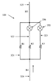
図1
図1は、本発明の流体システムを用いて有用な典型的なフローサイトメーターの構成部材の概略図を描いている。流動セル100は、流動セルチャンバー106と、試料入口ポート108と、シース流体入口ポート110とを含む。試料入口ポート108およびシース流体入口ポート110は、粒子を含む流体試料および粒子なしシース流体を流動セルチャンバー106へとそれぞれ供給するようになっている。流動セルチャンバー106は、キュベット102を貫通するキュベット通路104に接合される開口に集束している。
FIG.
FIG. 1 depicts a schematic diagram of typical flow cytometer components useful with the fluid system of the present invention.
使用時に、分析される粒子を含む試料流体が試料入口ポート108を介して流動セル100へと導入され、粒子なしシース流体がシース流体入口ポート110を介して流動セルへと導入される。これらの流体は、キュベット通路104を通って廃物レセプタクル(図示せず)に向けて出る。流動セルは、シース流体が試料流体と同軸の環状流を形成するように設計され、流体が流動セルの収束通路を通って対流的に加速するので、これにより粒子なしシース流体にて囲まれた流体の流れの中央に粒子を含む試料流体の水力学的に集束した流れを作り出す。ここでは、シース流体と試料流体とからなる組み合わせの流体の流れを「試料流」または「フローストリーム」あるいは「粒子流」と呼称する。
In use, a sample fluid containing the particles to be analyzed is introduced into the
試料流内の粒子の光学的分析は、試料流を検出領域120にて1つ以上の励起光源からの励起光にさらし、検出領域120からの放射光を1つ以上の光検出器(図示せず)を用いて検出することによって行われる。キュベット102は、少なくとも一部が光学的に透明な材料から構成されて光の励起および検出を可能にする。図1は、2つの励起光源の使用を描いている。励起光源118は、レンズ116によって合焦される第1の光束を検出領域120内の第1の調査箇所にて試料流に対し発する。励起光源119は、レンズ116によって合焦される第2の光束を検出領域120内の第2の調査箇所にて試料流に対し発し、この第2の調査箇所は、ある距離122だけ第1の調査箇所の下流にある。第2の光束を調査箇所にて第1の光束と本質的に平行に向け直すため、反射鏡またはビームスプリッター117が用いられる。
Optical analysis of the particles in the sample stream involves exposing the sample stream to excitation light from one or more excitation light sources in the
一般的に、それぞれ多数の励起光源に関し、多数の検出器(図示せず)が試料流の粒子から発せられる蛍光を検出するために存在し、それぞれの検出器は、規定した波長の範囲内の放射光を検出するように形成されている。加えて、追加の検出器が少なくとも1つの励起光源からの励起光を検出するために配され、これは励起光束に対して少ない角度で粒子により散乱される前方散乱光として呼称され、励起光束に対してほぼ直角に粒子により散乱される励起光は、側方散乱光として呼称される。フロー式粒子分析器にて用いるための適当な光検出器は、例えば光電子増倍管(PMT)やアバランシェフォトダイオード、フォトダイオードまたは他のあらゆる適当な光検出器具を含む。 In general, for each of a number of excitation light sources, a number of detectors (not shown) are present to detect fluorescence emitted from particles in the sample stream, and each detector is within a defined wavelength range. It is configured to detect emitted light. In addition, an additional detector is arranged to detect excitation light from at least one excitation light source, which is referred to as forward scattered light scattered by the particles at a small angle to the excitation light beam, The excitation light that is scattered by the particles at approximately right angles to it is referred to as side scattered light. Suitable photodetectors for use in the flow particle analyzer include, for example, a photomultiplier tube (PMT), an avalanche photodiode, a photodiode or any other suitable photodetector.
調査箇所の空間分離は、粒子が別々の異なる波長の励起光にそれぞれさらされることを可能にする。粒子がキュベット通路104を通って移動すると、これらは第1の調査箇所にて励起光源118からの励起光に最初にさらされる。次に、これらの粒子は第1の調査箇所を出てこれらが励起光源119からの励起光にさらされる第2の調査箇所へと移動する。これが第1の調査箇所から第2調査箇所へと移動するのに粒子がかかる時間は、ここでは「レーザー遅れ」として呼称される。
Spatial separation of the investigation sites allows the particles to be each exposed to different and different wavelengths of excitation light. As the particles move through the
このレーザー遅れは、第1の励起光にさらされた粒子の放射から得られる信号を第2の励起光にさらされた同じ粒子の放射からの信号と電子的に調和させるために用いられる重要なパラメーターであり、信号は同じ粒子が起源であるようにすべて取り扱われるようになっている。調査箇所間の所与の距離122に関するレーザー遅れは、キュベット通路104を通る流量に完全に依存する。少なくともこの理由のため、流動セルを通る流量を試料粒子の分析中には一定に維持すべきである。
This laser delay is an important factor used to electronically match the signal obtained from the emission of particles exposed to the first excitation light with the signal from the emission of the same particles exposed to the second excitation light. It is a parameter and the signals are all handled as if they originated from the same particle. The laser delay for a given
それぞれの調査箇所にて検出可能な試験粒子の試料を分析することによって、流動セルを通る流量を測定することができる。それぞれの粒子に関し、第1の励起光にさらされた粒子の放射から得られる信号と、第2の励起光にさらされた粒子の放射からの信号との間の時間が測定される。調査箇所間の距離122はこの機器の設計から知られているので、第1および第2の信号間の時間遅れは、検出領域120を通る流量の計算を可能にする。代わりに、規定した期間に亙って流動セルの下流の流体の累積を測定することにより、その流量を測定することができる。
By analyzing a sample of test particles detectable at each survey location, the flow rate through the flow cell can be measured. For each particle, the time between the signal obtained from the emission of the particle exposed to the first excitation light and the signal from the emission of the particle exposed to the second excitation light is measured. Since the
図2
図2は本発明の流体システムの構成部材の概略図を描いている。システムの真空度が真空ポンプ211によって創り出され、シース流体リザーバー202からのシース流体と、試料管201からの分析される粒子を含む試料流体とを流動セル100を通して引き込み、光学的分析が行われる(光学系を図示せず)。流動セルを出た試料流体およびシース流体の混合物である廃液が廃液リザーバー203へと排出される。
FIG.
FIG. 2 depicts a schematic diagram of the components of the fluid system of the present invention. The vacuum of the system is created by the
一般的にダイヤフラム型ポンプである真空ポンプ211によって創り出される真空の脈動は、脈動減衰器としても呼称されるアキュムレーター255によって減衰される。このアキュムレーターは、真空ポンプの行程容積の何倍(例えば10倍から1000倍)もの内部容積を持つシールされたキャニスターであってよい。
A vacuum pulsation created by a
変換器231は、真空ポンプ211によって創り出される圧力低下を大気圧に対して測定する。この圧力低下をここでは「静圧低下」として呼称する。この静圧低下は、アキュムレーター255の内部から好ましくは測定され、安定した測定値が得られるようになっている。
The
変換器231は通常、短い配管によってアキュムレーター255に結合され、この配管内の圧力がアキュムレーター内の圧力と等しくなっている。変換器231とアキュムレーター255とを接続する配管が変換器の近傍に配される空気抜き(例えば配管の内部を外気に接続する小径オリフィス)を含むことが望ましく、少量の空気がアキュムレーター内の真空によって引き込まれ、配管へと引き込まれてここを通ることを可能にする。配管を通る空気の流れが静圧低下の測定に対してほとんど影響を与えないように、この空気抜きを充分に小さくすべきである。オリフィス(変換器の近傍)からアキュムレーターの方に向けて配管を通るわずかな空気流は、アキュムレーターに存在するかも知れないどのような流体または泡が配管から変換器へと流入して測定値の精度に悪影響を与える可能性があることを阻止する。
The
変換器232は、キュベット102を横切る圧力低下を測定する(流動セルの上流からアキュムレーター255まで測定される)。この圧力低下をここでは「動圧低下」として呼称される。所定の全体流量をキュベットに通すため、動圧低下は一定である。従って、真空ポンプ211の出力を調節して一定の動圧低下を与えることにより、キュベットを通る一定の全体流量を維持することができる。
The
試料流体は、試料ライン220を通り、試料入口ポート108(図1に示す)を介して流動セル100へと引き込まれる。この試料通路の全体は流体抵抗R0を有する。
Sample fluid is drawn through the
シース流体は、可変抵抗流体抵抗器222を通り、シース流体入口ポート110(図1に示す)を介して流動セル100へと引き込まれる。好ましい一実施形態において、可変抵抗流体抵抗器の流体抵抗は、多数の別々な設定の流体抵抗に調整可能である。他の実施形態において、可変抵抗流体抵抗器の流体抵抗は、あらかじめ規定された範囲に亙って連続的に調整可能である。
The sheath fluid is drawn through the variable
流動セル100へと引き込まれる試料流体とシース流体との相対的な割合は、試料ラインの流体抵抗R0と、可変抵抗流体抵抗器222の流体抵抗との割合に依存する。従って、可変抵抗流体抵抗器222の流動抵抗を調整することにより、シース流体に対する試料流体の割合を制御することができる。動圧低下を一定に維持することにより流動セルを通る全体の流量が一定に保持される場合、可変抵抗流体抵抗器222の有効な流体抵抗のそれぞれ低減は、試料流体の割合の減少およびシース流体の割合の増加を結果として生ずる。従って、可変抵抗流体抵抗器222の全体の流体抵抗を適切に調節することにより、一定の流量を流動セルに通しつつ望ましい試料の割合を選択することができる。
The relative proportion of sample fluid and sheath fluid drawn into the
弁253は、流動セルを通る流れを完全に止めることを可能にする。休止は、例えばそれぞれ試料の分析の後に新たな試料供給源に変更することを可能にする。本システムにおいて、流動セルとポンプとの間の流体通路に配された弁を閉じることにより、流体の流動を休止させることができる。この弁が閉じられている時、動圧低下はゼロまで低下し、この動圧低下とポンプとの間にある第1のフィードバックループが停止し、静圧低下とポンプとの間にある第2のフィードバックループが機能する。この第2のフィードバックループは、休止状態中の静圧低下を一定レベルに維持し、好ましくはこのシステムを休止する前の運転状態の間(第1のフィードバックループの制御を受けている間)にこのシステムに存在した静圧低下を維持することを可能にする。流動セルを通る流体の流動が再開すると、ポンプの制御が元の第1のフィードバックループへと切り替えられ、試料流量の変更後であっても流動セルを横切る一定の流れを維持することを可能にする。これらフィードバック制御回路間のこの切り替えは、運転状態と休止状態との間の移行中における真空度の大きな変動を排除すると共にすべての試料が一定の割合で流動セルを通ることを維持する。
The
弁251は、シース流体の流れを完全に止めることを可能にする。弁251は、シース流体の流れを一時的に止めるため、また試料ライン220に対する試料管201の結合に追随する試料流体の流量を一時的に増大して(「増幅して」)試料流体を流動セル100に引き込むために要する時間を短くするために用いられる。試料流体が流動セルに達すると、弁251が開かれ、シース流体の流れが水力学的に集束した流れを作り、試料およびシース流体の流量が分析のための望ましい割合へと戻る。弁251および253は、相互に協調して好ましくは自動制御を受け、前記弁251を開く前に弁253があらかじめ設定された時間だけ開かれ、弁251を開く前の前記流動セルに創り出された真空度を可能にしよう。
The
切り替え手段263を持つコントローラー261は、一定の動圧低下を与える真空ポンプ211の出力の調節と、一定の静圧低下を与える真空ポンプ211の出力の調節との間の切り替えを制御する。一定の動的低下を維持するため、コントローラーは変換器232により測定された動圧低下を記憶された望ましい動圧低下PDと比較する。この望ましい動圧低下PDは、流動セルを通る望ましい流量をもたらす動圧低下として、機器のセットアップ中に決定される。一定の静圧低下を維持するため、コントローラーは、変換器231によって測定された動圧低下を記憶された望ましい静圧低下PSと比較する。この望ましい静圧低下PSは、流動セルを通る望ましい流量で作動する機器に対応する測定された静圧低下であり、これは可変抵抗流体抵抗器の選択された設定に依存する。可変抵抗流体抵抗器のあらかじめ規定した抵抗の設定にそれぞれ対応する多数の望ましい静圧低下PSの値を記憶させておくことができる。代わりに、システムの休止直前に望ましい静圧低下PSを記憶させ、このシステムを休止する直前に作用していた可変抵抗流体抵抗器の同じ抵抗設定にてシステムを再起動させることができる。
The
好ましくは、圧力低下フィードバック回路(コントローラー261を経由する)と弁251および253との自動制御が相互に協調してもたらされよう。
Preferably, automatic control of the pressure drop feedback circuit (via controller 261) and
フローセンサー235は試料ライン220に配されて試料流体の流量の直接的な測定をもたらす。毎分ナノリットルに至るまでの測定範囲を持つ適当な高精度の液体フローセンサーおよび液体流量計は、例えば Sensirion Inc.(カリフォルニア州 Westlake Village)から商業的に入手可能である。フローセンサー235は必須ではないが、流通システムのセットアップを容易にする。機器のセットアップ(システムの較正)中に可変抵抗流体抵抗器222の流体抵抗が調整されて試料流体に対するシース流体の望ましい割合を与え、フローセンサーは結果として生ずる試料流体の流量を独自に測定することをもたらす。代わりに、周知の濃度の試験粒子を含む試料を分析することによる如き、他の手段によって試料流体の流量を測定することができる。試験粒子の検出割合を測定することによって、試料ライン220における流量を推定することができる。
A
図6を参照して以下に記述されるように、機器の較正中に試料流体の望ましい流量を得るため、可変抵抗流体抵抗器222の流体抵抗の調整を自動化させることができる。
As described below with reference to FIG. 6, adjustment of the fluid resistance of the variable
図3
図3は、個々に異なるレベルの流体抵抗を提供するように設計した可変抵抗流体抵抗器の一実施形態の概略図を描いている。この可変抵抗流体抵抗器内には、異なる流体抵抗をそれぞれもたらす多数の平行な流体通路があり、全体として可変抵抗流体抵抗器の他の全体の流体抵抗レベルは、この可変抵抗流体抵抗器を通して流すために使用することができる他の内部流体通路を選択することによって達成される。
FIG.
FIG. 3 depicts a schematic diagram of one embodiment of a variable resistance fluid resistor designed to provide different levels of fluid resistance. Within this variable resistance fluid resistor there are a number of parallel fluid passages that each provide a different fluid resistance, and overall other overall fluid resistance levels of the variable resistance fluid resistor flow through the variable resistance fluid resistor. This is accomplished by selecting other internal fluid passages that can be used.
可変抵抗流体抵抗器320は、流体抵抗R1およびR2およびR2をそれぞれ与える内部流体通路321および322および323を含む。シース流体の流れに用いることができるこれら3つの平行な流体通路のどれを選択するかは、流体通路322を通る流れを制御する2方向弁355と、流体通路323を通る流れを制御する2方向弁356とによって制御される。流体通路321はシース流体を流すために常に開いている。可変抵抗流体抵抗器320の最大抵抗は、両方の弁356および355を閉じることにより選択される単一の流体通路321を通る流れによって与えられる。これら弁の一方または他方あるいは両方を開き、流体通路321と平行な少なくとも1つの流体通路を与えると、可変抵抗流体抵抗器320を通る全体の流体抵抗を減少させる。
Variable
可変抵抗流体抵抗器320は3つの内部流体通路を含むけれども、規定した流体抵抗をそれぞれ持った多数の異なる平行な流体通路と、これら流体通路の選択を可能にするための弁とを用い、本質的に任意の数の個別レベルの流体抵抗を達成することができることは明確であろう。一般に、一連の平行なN個の抵抗を有する回路の等価抵抗は、以下のように、構成する平行通路の抵抗値に関係する。
Although the variable

ここでRは回路の等価抵抗であり、それぞれRiは平行な通路Iの抵抗であり、合計はN個の平行な通路の全体に亙っている。 Where R is the equivalent resistance of the circuit, Ri is the resistance of the parallel path I, respectively, and the sum totals over N parallel paths.
弁356および355により規定される追加の流体通路のそれぞれに関し、内部流体通路321および322および323が分岐する箇所から、これら内部流体通路が再び接続する箇所まで、平行な回路を通る可変抵抗流体抵抗器320の等価抵抗を以下の表に示す。
For each of the additional fluid passages defined by
可変抵抗流体抵抗器320の有効流体抵抗をそれぞれ低減することは、流動セルを通る試料流体の流れに対するシース流体の割合の増加を結果としてもたらす。流動セルを通る全体の流量が一定の動圧低下を維持することにより一定に保持されている場合、可変抵抗流体抵抗器320の有効流動抵抗のそれぞれの低減は、試料流体の流量の減少を結果として生ずる。従って、可変抵抗流体抵抗器の全体の流体抵抗を適切に調節することによって、望ましい試料流量を選択することができ、同時に流動セルを通る一定流量を維持する。
Reducing each effective fluid resistance of variable
シース流体リザーバー202から流動セル100(図2に示す)までの全体のシース流体通路は、抵抗R4を有するシース流体ライン324と、可変抵抗流体抵抗器320と、抵抗R5を有するシース流体ライン325とを含む。シース流体通路の全体の抵抗は、これら3つの部品の抵抗の合計、すなわちR4+R5+可変抵抗流体抵抗器320の抵抗である。一般的に、可変抵抗流体抵抗器320は、シース流体通路の全体の抵抗の大部分を与えよう。
The entire sheath fluid path from the
図4
図4aおよび図4bは、抵抗が連続的に可変である可変抵抗流体抵抗器の他の一実施形態の2つの概略図面を描いている。この実施形態において、流体抵抗の調節は、配管の長さを圧縮し、これによって内径を変更することにより達成される。
FIG.
Figures 4a and 4b depict two schematic drawings of another embodiment of a variable resistance fluid resistor in which the resistance is continuously variable. In this embodiment, adjustment of fluid resistance is accomplished by compressing the length of the tubing and thereby changing the inner diameter.
シース流体ライン421は、臑動ポンプ配管の如き圧縮可能な配管である。シース流体ライン421の一部は、中央支柱464の周りに巻き付けられ、円筒状のベースハウジング460内に配されている。ベースハウジングの穴は、配管がつぶされることなくベースハウジングに入ると共に出ることを可能にする。円形の上板464がベースハウジングの上端開口の内側に配され、シース流体ライン421のコイルを収容する円筒状のキャビティーを形成するようになっている。上板462は、中央支柱464が上板を貫通して延在することを可能にする穴を含み、上板462がベースハウジングへと下方に滑動することができるようになっている。中央支柱の上端にはねじ山が切られ、ナット466がこの中央支柱の上端にねじ止めされている。ナットをねじ込むと、上板462がシース流体ライン421のコイルの上端を押し付けてシース流体ラインを圧縮し、その流体抵抗を増大させる。
The
シース流体ライン421の流体抵抗は、連続的に可変であってナット466により加えられる力によって制御され、抵抗の変更に関して正確な制御が可能である。配管の径およびコイルの巻き数は、特定の用途に必要とされる範囲と制御とをもたらすように選択されよう。シース流体の流動通路は極めて単純であり、清掃のために容易に洗い流すことができ、細胞や粒子を捕捉する可能性がある内端縁や他の構造物を有していない。
The fluid resistance of the
流体抵抗の遠隔制御をもたらすため、可変抵抗流体抵抗器の流体抵抗の調節を自動化させることができることは明らかであろう。 It will be apparent that the adjustment of the fluid resistance of the variable resistance fluid resistor can be automated to provide remote control of the fluid resistance.
図5
図5は、抵抗が連続的に可変である可変抵抗流体抵抗器の他の一実施形態の概略図を描いている。シース流体ライン521は、臑動ポンプ配管の如き圧縮可能な配管である。このシース流体ライン521は、入口ポート525を通る圧力による気体または流体で満たされるシールされた加圧タンク522を貫通する。タンク内の圧力変更がシース流体ラインを圧縮して流体抵抗を変更する。
FIG.
FIG. 5 depicts a schematic diagram of another embodiment of a variable resistance fluid resistor whose resistance is continuously variable. The
流体抵抗の遠隔制御をもたらすため、可変抵抗流体抵抗器の流体抵抗の調節を自動化させることができることは明らかであろう。 It will be apparent that the adjustment of the fluid resistance of the variable resistance fluid resistor can be automated to provide remote control of the fluid resistance.
図6
図6は、システム較正中に事前選択した試料流体の流量を取得するため、試料流体の流量を自動的に調整する自動化したフィードバック制御回路を描いている。連続的に可変の可変抵抗流体抵抗器622は、サーボ機構を用いた流体抵抗の調節を可能にするように形成されている。適当な可変抵抗流体抵抗器の例が図4に描かれているように、ナット466はサーボモーターを用いて調整されるか、または図5に描かれているように、サーボモーターの制御により圧力供給源を調節する。コントローラー661は、フローセンサー235によって測定された流量を記憶した望ましい流量FRと比較し、測定された流量がこの望ましい流量FRと合致するまで可変抵抗流体抵抗器622の流体抵抗を調節する。
FIG.
FIG. 6 depicts an automated feedback control circuit that automatically adjusts the sample fluid flow rate to obtain a preselected sample fluid flow rate during system calibration. The continuously variable variable
システム較正
一般に、本発明の真空駆動流体工学を含むフロー式粒子分析器の初期較正は、以下のステップを用いて行われることが好ましい。
System Calibration In general, the initial calibration of a flow particle analyzer including the vacuum driven fluidics of the present invention is preferably performed using the following steps.
A.可変流体抵抗器の抵抗は、都合の良いあらゆる設定で設定される。流動セルを通る望ましい流量を維持するために必要とされる動圧低下は、連続的な可変流体抵抗の抵抗値に依存しないので、このステップにて用いられる抵抗の設定は重要ではない。 A. The resistance of the variable fluid resistor is set at any convenient setting. Since the dynamic pressure drop required to maintain the desired flow rate through the flow cell does not depend on the resistance value of the continuously variable fluid resistance, the resistance setting used in this step is not critical.
B.流動セルを通る望ましい流量が得られそうな動圧低下を決定する。この動圧低下の値はフィードバック制御システム内に記憶され、一定の動圧低下を維持するために用いられる。 B. Determine the dynamic pressure drop at which the desired flow rate through the flow cell is likely to be obtained. This dynamic pressure drop value is stored in the feedback control system and is used to maintain a constant dynamic pressure drop.
C.望ましい試料流量を与えるために可変抵抗流体抵抗器が調整され、同時に動圧低下を維持する。この試料流量は、上述したように、試料流体ラインと直列の流量計によって測定されることが望ましい。個別の値の可変抵抗流体抵抗器を用いた実施形態において、望ましい試料流量のそれぞれを取得するためのそれぞれ個別の抵抗レベルに対する調整はステップ(C)にてなされる。好ましくは、それぞれの試料流量に対応する静圧低下は、このシステムの休止および再起動の際に使用するために記憶される。 C. A variable resistance fluid resistor is adjusted to provide the desired sample flow rate while maintaining a dynamic pressure drop. This sample flow rate is preferably measured by a flow meter in series with the sample fluid line, as described above. In embodiments using individual value variable resistance fluid resistors, adjustments to each individual resistance level to obtain each desired sample flow rate are made in step (C). Preferably, the static pressure drop corresponding to each sample flow rate is stored for use during pauses and restarts of the system.
例えば、図3に描いたような個々の値の可変流体抵抗器を用いた場合、この可変抵抗流体抵抗器は、内部の流体通路321および322および323のための名目的に長い長さを持つ配管で最初に形成される。ステップ(C)における調整は、最初に閉じた弁356および355を用いて行われ、シース流体が流体通路321のみを通って移動するようになっている。これはシース流体に対する最も高い抵抗レベルを与え、これはシース流体に対する試料流体の最も高い割合、つまり試料流体の最多流量に対応する。流体通路321が例えば配管の長さを変更することにより、動圧低下を維持しつつ望ましい「高い」試料流量を得るように調整される。次に、シース流体が流体通路321および322を通って並列に移動するように、弁356を開く。これはシース流体に対して減少した抵抗レベルを与え、これは減少した試料流体の流量に対応する。流体通路322は、動圧低下を維持しつつ望ましい「中位」の試料流量を与えるように調整される。次に、シース流体が流体通路321および322および323を通って並列に流れるように、弁355を開く。これはシース流体に対してさらに減少した抵抗レベルを与え、これはさらに減少した試料の流体流量に対応する。流体通路323は、動圧低下を維持しつつ望ましい「低い」試料流量を与えるように調整される。上述したセットアップが3つの個別の流体抵抗レベルの設定を記述しているけれども、2つの弁の存在は、個別の流体の抵抗レベルを4つまで可能にすることが明白であろう。
For example, when using individual value variable fluid resistors as depicted in FIG. 3, this variable resistance fluid resistor has a nominally long length for the internal
連続的に可変の可変抵抗流体抵抗器を用いた実施形態において、望ましい試料流量が好ましくは自動化された制御により得られるまで、動圧低下を維持しつつ抵抗レベルが調整される。例えば、連続的な個別の値と、可変抵抗流体抵抗器と、図6に描いたような制御フィードバック回路とを用い、望ましい流量が得られるまで、測定された試料流量に応じて抵抗が自動的に調節される。 In an embodiment using a continuously variable variable resistance fluid resistor, the resistance level is adjusted while maintaining the dynamic pressure drop until the desired sample flow rate is obtained, preferably by automated control. For example, using a series of discrete values, a variable resistance fluid resistor, and a control feedback circuit as depicted in FIG. 6, the resistance automatically depends on the measured sample flow rate until the desired flow rate is obtained. Adjusted to.
システムの休止および再起動
本発明の一形態は、フロー式流体分析器の真空駆動流体システムを休止するための改良された方法にあり、これは運転状態と休止状態との間の切り替え時に真空ポンプの出力レベルを一定に維持することを容易にする。弁253を閉じることによって、流動セルを通る流体の流れを止める(すなわち、システムを休止する)ことができる。ポンプ211によって引き込まれる真空の変動を回避するため、真空ポンプの制御が好ましくは静圧フィードバックループへと自動的に切り替えられ、静圧低下をこの流れを休止する直前に存在していた一定値に維持する。システムが休止すると、このシステムを稼働しつつ望ましい動圧低下を維持するために必要とされる真空ポンプの出力レベルを、対応する静圧低下(このシステムを休止する直前に測定される)に維持するために必要とされる出力レベルと等しくすべきである。この流動を休止する直前の静圧低下は、上述したような機器の較正時か、あるいは弁253を閉じる前の静圧低下を測定することにより、決定される。
System Pause and Restart One aspect of the present invention is an improved method for pausing a vacuum-driven fluid system of a flow fluid analyzer, which is a vacuum pump when switching between operating and dormant states Makes it easy to maintain a constant output level. By closing
システムを再起動するために弁253が開かれ、真空ポンプ211が流動セルを通って真空を引き込むことを可能にする。真空ポンプの制御が好ましくは自動的に動圧フィードバックループへと切り替えられ、ポンプに対する出力が調整されて動圧低下をセットアップの際に決定した値に維持し、流動セルを通る望ましい流量を与える。
このシステムは、試料管の交換を可能にするために定期的に休止されよう。再起動時には、新しい試料管からの試料流体が流動セルに達する前に試料流体ラインを通って引き込まれることが必要である。試料流体ラインが新たな試料管からの試料流体で満たされるまで試料の初期の流れを加速する(押し上げる)ことが望ましい。試料流体の最大流量は、弁251を閉じてシース流体の流れを絶つことにより達成される。システムを再起動させる場合、弁251を開く前に流動セル内に真空を得ることができるようにするため、この弁251を開く前に試料流体ラインの流量および容積に基づいてあらかじめ設定した時間だけ弁253を開き、これによって弁251を開く前に試料ラインを通って流動セルへと試料流体を引き込む。
The system will be periodically paused to allow sample tube replacement. Upon restart, sample fluid from a new sample tube needs to be drawn through the sample fluid line before reaching the flow cell. It is desirable to accelerate (push up) the initial flow of the sample until the sample fluid line is filled with sample fluid from a new sample tube. The maximum flow rate of the sample fluid is achieved by closing
Claims (11)
試料流体入口ポートおよびシース流体入口ポートおよび出口ポートおよびキュベットを有し、前記キュベットが入口端および出口端を有するキュベット通路を含み、前記入口端が前記試料入口ポートおよび前記シース流体入口ポートと流体連通状態にあり、前記出口端が前記出口ポートと流体連通状態にある流動セルと、
前記試料入口ポートと流体連通状態にあって、試料流体容器から粒子を含有する試料流体を供給するための試料流体ラインと、
前記シース流体入口ポートと流体連通状態にあって、シース流体リザーバーからシース流体を供給するためのシース流体ラインと、
前記出口ポートと流体連通状態にある出口ラインと、
制御可能な出力レベルを有し、前記出口ラインと真空連通状態にあって前記出口ラインを真空引きするように形成され、それによって前記流動セルを介して前記試料流体およびシース流体を吸引する真空ポンプと、
前記シース流体入口ポートから前記キュベット出口ポートまでの圧力低下を測定するように形成された第1のセンサーと、
この第1のセンサーによって測定された圧力低下に応じて前記真空ポンプの出力を調整するように形成された第1の制御フィードバック回路と、
前記キュベット出口ポートから大気圧までの圧力低下を測定するように形成された第2のセンサーと、
この第2のセンサーによって測定されて圧力低下に応じて前記真空ポンプの出力を調整するように形成された第2の制御フィードバック回路と
を具え、前記試料流体ラインまたは前記シース流体ラインが可変抵抗流体抵抗器を構成することを特徴とする流体システム。 A fluid system for a flow particle analyzer comprising:
A sample fluid inlet port and a sheath fluid inlet port and an outlet port and a cuvette, the cuvette including a cuvette passage having an inlet end and an outlet end, wherein the inlet end is in fluid communication with the sample inlet port and the sheath fluid inlet port A flow cell in a state where the outlet end is in fluid communication with the outlet port;
A sample fluid line in fluid communication with the sample inlet port for supplying a sample fluid containing particles from a sample fluid container;
A sheath fluid line in fluid communication with the sheath fluid inlet port for supplying sheath fluid from a sheath fluid reservoir;
An outlet line in fluid communication with the outlet port;
A vacuum pump having a controllable output level and configured to evacuate the outlet line in vacuum communication with the outlet line, thereby sucking the sample fluid and sheath fluid through the flow cell When,
A first sensor configured to measure a pressure drop from the sheath fluid inlet port to the cuvette outlet port;
A first control feedback circuit configured to adjust the output of the vacuum pump in response to a pressure drop measured by the first sensor;
A second sensor configured to measure a pressure drop from the cuvette outlet port to atmospheric pressure;
A second control feedback circuit configured to adjust the output of the vacuum pump as measured by the second sensor in response to a pressure drop, wherein the sample fluid line or the sheath fluid line is a variable resistance fluid A fluid system comprising a resistor.
前記出口ラインと直列に配され、前記流動セルの外への前記シース流体の流動を制御するように形成された第2の弁と、
これら第1および第2の弁を操作するように結合された弁コントローラーと
をさらに具えたことを特徴とする請求項2に記載の流体システム。 A first valve disposed in series with the sheath fluid line and configured to control the flow of the sheath fluid to the flow cell;
A second valve disposed in series with the outlet line and configured to control the flow of the sheath fluid out of the flow cell;
The fluid system of claim 2, further comprising: a valve controller coupled to operate the first and second valves.
この流量計および前記可変抵抗流体抵抗器を操作するように結合され、当該流量計によって測定された前記流量に応じて前記可変抵抗流体抵抗器の抵抗を自動的に調整するように形成されたコントローラーと
をさらに具えたことを特徴とする請求項7に記載の流体システム。 A flow meter configured to measure a flow rate in the sample fluid line;
A controller coupled to operate the flow meter and the variable resistance fluid resistor and configured to automatically adjust the resistance of the variable resistance fluid resistor in response to the flow rate measured by the flow meter The fluid system according to claim 7, further comprising:
Applications Claiming Priority (2)
| Application Number | Priority Date | Filing Date | Title |
|---|---|---|---|
| US40799010P | 2010-10-29 | 2010-10-29 | |
| PCT/US2011/057445 WO2012058142A1 (en) | 2010-10-29 | 2011-10-24 | Dual feedback vacuum fluidics for a flow-type particle analyzer |
Publications (3)
| Publication Number | Publication Date |
|---|---|
| JP2014503792A JP2014503792A (en) | 2014-02-13 |
| JP2014503792A5 JP2014503792A5 (en) | 2014-10-16 |
| JP5771696B2 true JP5771696B2 (en) | 2015-09-02 |
Family
ID=44983697
Family Applications (1)
| Application Number | Title | Priority Date | Filing Date |
|---|---|---|---|
| JP2013536693A Active JP5771696B2 (en) | 2010-10-29 | 2011-10-24 | Dual feedback vacuum fluidics for flow particle analyzers |
Country Status (9)
| Country | Link |
|---|---|
| US (2) | US8528427B2 (en) |
| EP (1) | EP2633283B1 (en) |
| JP (1) | JP5771696B2 (en) |
| CN (1) | CN103201611B (en) |
| AU (1) | AU2011320713B2 (en) |
| ES (1) | ES2732355T3 (en) |
| SG (1) | SG189532A1 (en) |
| WO (1) | WO2012058142A1 (en) |
| ZA (1) | ZA201302955B (en) |
Families Citing this family (65)
| Publication number | Priority date | Publication date | Assignee | Title |
|---|---|---|---|---|
| CN1886315B (en) | 2003-10-30 | 2012-11-28 | 塞通诺米/St有限责任公司 | Multilayer hydrodynamic sheath flow structure |
| WO2011000088A1 (en) * | 2009-07-02 | 2011-01-06 | The Governors Of The University Of Alberta | Particle classifier |
| SG183932A1 (en) * | 2010-03-10 | 2012-10-30 | Beckman Coulter Inc | Generating pulse parameters in a particle analyzer |
| CN104813157A (en) * | 2012-11-29 | 2015-07-29 | 细胞流有限责任公司 | Fluidic system and method |
| WO2014153107A1 (en) | 2013-03-14 | 2014-09-25 | Cytonome/St, Llc | Hydrodynamic focusing apparatus and methods |
| BR112015019969B1 (en) | 2013-03-15 | 2021-01-05 | Iris International, Inc. | method for obtaining particle images using a particle analysis system configured for combined hydrodynamic focusing of viscosity and geometry, and a particle analysis system that performs combined hydrodynamic focusing of viscosity and geometry for image particles in a sample of blood |
| US9372143B2 (en) * | 2013-05-15 | 2016-06-21 | Captl Llc | Scanning image flow cytometer |
| WO2015061216A1 (en) * | 2013-10-21 | 2015-04-30 | Cytoflow, Llc | Cytometer flowcell |
| CN103837462B (en) * | 2014-03-03 | 2016-10-05 | 中国科学院苏州生物医学工程技术研究所 | A kind of small-sized flow cytometer liquid-way system |
| JP5873126B2 (en) * | 2014-04-04 | 2016-03-01 | 日本電信電話株式会社 | Liquid feeding method and liquid feeding system |
| WO2016089521A1 (en) | 2014-12-04 | 2016-06-09 | Becton, Dickinson And Company | Flow cytometry cell sorting systems and methods of using the same |
| WO2016093970A1 (en) | 2014-12-10 | 2016-06-16 | Becton, Dickinson And Company | Methods for optically aligning light collection components and optically aligned light collection systems thereof |
| WO2016100954A1 (en) | 2014-12-19 | 2016-06-23 | Captl Llc | Flow cytometry using hydrodynamically planar flow |
| JP6937697B2 (en) | 2015-02-18 | 2021-09-22 | ベクトン・ディキンソン・アンド・カンパニーBecton, Dickinson And Company | Photodetection system and how to use it |
| ES2965719T3 (en) | 2015-06-17 | 2024-04-16 | Becton Dickinson Co | Optical detector scattering plug unit having a detachable scattering bar and methods of using the same |
| US10036698B2 (en) | 2015-06-19 | 2018-07-31 | Captl Llc | Time-sequential cytometry |
| AU2016339956B2 (en) | 2015-10-13 | 2021-07-01 | Omega Biosystems Incorporated | Multi-modal fluorescence imaging flow cytometry system |
| US20190086319A1 (en) | 2016-03-10 | 2019-03-21 | Becton, Dickinson And Company | Methods of evaluating a cellular sample for her-2/neu expression and compositions for practicing the same |
| KR20180129832A (en) | 2016-03-17 | 2018-12-05 | 비디 바이오사이언시스 | Cell selection using a high-efficiency fluorescence flow cytometer |
| WO2017184776A1 (en) | 2016-04-22 | 2017-10-26 | Becton, Dickinson And Company | High density deposition for array production |
| KR102381176B1 (en) | 2016-05-12 | 2022-04-01 | 비디 바이오사이언시스 | Fluorescence Imaging Flow Cytometry with Improved Image Resolution |
| CN109477785B (en) | 2016-09-13 | 2022-09-27 | 贝克顿·迪金森公司 | Flow cytometer with optical equalization |
| WO2018067210A1 (en) | 2016-10-03 | 2018-04-12 | Becton, Dickinson And Company | Methods and systems for determining a drop delay of a flow stream in a flow cytometer |
| EP3541536A4 (en) * | 2016-11-19 | 2020-12-23 | Cytek Biosciences, Inc. | Flow cytometry systems with stepper flow control valve |
| US10436697B2 (en) * | 2016-11-19 | 2019-10-08 | Cytek Biosciences, Inc. | Flow cytometery system with fluidics control system |
| ES2950436T3 (en) | 2016-12-14 | 2023-10-10 | Becton Dickinson Co | Methods and compositions to obtain an assessment of tuberculosis in a subject |
| WO2018148098A2 (en) | 2017-02-08 | 2018-08-16 | Becton, Dickinson And Company | Dried dye reagent devices and methods for making and using the same |
| US10585031B2 (en) | 2017-02-27 | 2020-03-10 | Becton, Dickinson And Company | Light detection systems and methods for using thereof |
| US10613020B2 (en) * | 2017-08-10 | 2020-04-07 | The Boeing Company | Burr detection systems and methods |
| US10801617B2 (en) | 2018-01-05 | 2020-10-13 | Cnh Industrial America Llc | Propel system with active pump displacement control for balancing propel pump pressures in agricultural vehicles |
| US11346762B2 (en) | 2018-01-23 | 2022-05-31 | Becton, Dickinson And Company | Systems for dynamic light detection obscuration and methods for using thereof |
| US10844228B2 (en) | 2018-03-30 | 2020-11-24 | Becton, Dickinson And Company | Water-soluble polymeric dyes having pendant chromophores |
| EP3785017A4 (en) | 2018-04-27 | 2022-01-26 | Becton, Dickinson and Company | Collection systems for flow cytometrically sorted samples and methods of using the same |
| JP7416729B2 (en) | 2018-06-19 | 2024-01-17 | ベクトン・ディキンソン・アンド・カンパニー | Variable multiplexing switch, system, and method of use for detector arrays |
| CN112771365A (en) | 2018-06-28 | 2021-05-07 | 贝克顿·迪金森公司 | Integrated pre-amplification light detection system and use method thereof |
| CN112823275A (en) * | 2018-08-15 | 2021-05-18 | 贝克顿·迪金森公司 | Flow and vacuum controlled fluid management system for flow particle analyzer |
| CN109357991B (en) * | 2018-09-27 | 2020-05-26 | 清华大学 | Mass spectrum flow cytometry sample introduction and ionization device based on marking-free principle |
| US11035776B2 (en) | 2018-10-30 | 2021-06-15 | Becton, Dickinson And Company | Particle sorting module with alignment window, systems and methods of use thereof |
| US11237093B2 (en) * | 2018-12-10 | 2022-02-01 | Bio-Rad Laboratories, Inc. | External fluidics system for flow cytometer |
| US11009400B2 (en) | 2018-12-28 | 2021-05-18 | Becton, Dickinson And Company | Methods for spectrally resolving fluorophores of a sample and systems for same |
| WO2020163023A1 (en) | 2019-02-08 | 2020-08-13 | Becton, Dickinson And Company | Droplet sorting decision modules, systems and methods of use thereof |
| WO2020197787A1 (en) | 2019-03-22 | 2020-10-01 | Becton, Dickinson And Company | Spectral unmixing of fluorescence imaging using radiofrequency-multiplexed excitation data |
| US11268890B2 (en) | 2019-03-29 | 2022-03-08 | Becton, Dickinson And Company | Parameters for use in particle discrimination |
| CN111796111A (en) * | 2019-04-08 | 2020-10-20 | 爱科来株式会社 | Liquid feeding method and analyzer |
| JP7175231B2 (en) * | 2019-04-08 | 2022-11-18 | アークレイ株式会社 | Specimen analysis method and specimen analysis device |
| JP7312135B2 (en) * | 2019-04-08 | 2023-07-20 | アークレイ株式会社 | Liquid transfer method and analyzer |
| EP3969881A4 (en) | 2019-05-14 | 2023-01-25 | Becton, Dickinson and Company | Phase-calibration for imaging flow cytometry |
| EP3977103A4 (en) | 2019-05-30 | 2023-06-28 | Becton, Dickinson and Company | Phase-correction of radiofrequency-multiplexed signals |
| WO2021007075A1 (en) | 2019-07-10 | 2021-01-14 | Becton, Dickinson And Company | Reconfigurable integrated circuits for adjusting cell sorting classification |
| WO2021055732A1 (en) * | 2019-09-20 | 2021-03-25 | Kansas State University Research Foundation | Methods and apparatus for contactless orthographic imaging of aerosol particles |
| EP4062147A4 (en) | 2019-11-20 | 2023-01-18 | Becton, Dickinson and Company | A light detection module with adjustable sensitivity |
| WO2021127364A1 (en) | 2019-12-20 | 2021-06-24 | Becton, Dickinson And Company | Methods for quantitating extra-cellular vesicle surface markers, and compositions for practicing the same |
| WO2021154579A1 (en) | 2020-01-31 | 2021-08-05 | Becton, Dickinson And Company | Methods and systems for adjusting a training gate to accommodate flow cytometer data |
| EP4100720A4 (en) | 2020-02-07 | 2023-07-26 | Becton, Dickinson and Company | Clustered wavelength division light detection systems and methods of using the same |
| WO2021173418A1 (en) | 2020-02-26 | 2021-09-02 | Becton, Dickinson And Company | Light detection systems having a secondary light scatter detector and methods for using same |
| WO2021173296A1 (en) | 2020-02-27 | 2021-09-02 | Becton, Dickinson And Company | Methods for identifying saturated data signals in cell sorting and systems for same |
| US11874213B2 (en) | 2020-03-17 | 2024-01-16 | Becton, Dickinson And Company | Gain matched amplifiers for light detection |
| WO2021221884A1 (en) | 2020-04-28 | 2021-11-04 | Becton, Dickinson And Company | Method for index sorting unique phenotypes and systems for same |
| CN115917293A (en) | 2020-04-29 | 2023-04-04 | 贝克顿·迪金森公司 | Method and system for regulating and synchronizing detection in flow cytometer |
| EP4147029A4 (en) | 2020-05-06 | 2023-11-01 | Becton, Dickinson and Company | Methods and systems for characterizing spillover spreading in flow cytometer data |
| US11965813B2 (en) | 2020-08-03 | 2024-04-23 | Cytek Biosciences, Inc. | Methods and apparatus for central source pressure-based cytometer fluidics system |
| US20220341838A1 (en) * | 2021-04-23 | 2022-10-27 | Becton, Dickinson And Company | Fluid management system for an analyzer and/or sorter type flow type particle analyzer |
| US20230053122A1 (en) | 2021-08-10 | 2023-02-16 | Becton, Dickinson And Company | Clamps for operably coupling an optical component to a mounting block, and methods and systems for using the same |
| US20230046207A1 (en) | 2021-08-10 | 2023-02-16 | Becton, Dickinson And Company | Outlet fittings for reducing bubbles at the interface with a flow cell, and flow cytometers and methods using the same |
| WO2023239566A1 (en) * | 2022-06-06 | 2023-12-14 | Becton, Dickinson And Company | Fluidic resistance units, as well as flow cytometers and methods involving the same |
Family Cites Families (36)
| Publication number | Priority date | Publication date | Assignee | Title |
|---|---|---|---|---|
| JPS60140139A (en) * | 1983-12-27 | 1985-07-25 | Toa Medical Electronics Co Ltd | Particle counting apparatus |
| US5395588A (en) | 1992-12-14 | 1995-03-07 | Becton Dickinson And Company | Control of flow cytometer having vacuum fluidics |
| US5915925A (en) | 1997-01-07 | 1999-06-29 | North, Jr.; Howard L. | Pulseless liquid supply system for flow cytometry |
| JP3608066B2 (en) * | 1997-01-14 | 2005-01-05 | 株式会社日立製作所 | Particle analyzer |
| IL124514A (en) * | 1998-05-17 | 2002-02-10 | Davidson Chaim | Method and apparatus for magnetically separating selected particles, particularly biological cells |
| EP1018644A2 (en) * | 1999-01-06 | 2000-07-12 | Bayer Corporation | Variable rate particle counter and method of use |
| GB2381589B (en) * | 1999-05-26 | 2003-09-10 | Cyber Instr Technology Llc | Wide range gas flow system with real time flow measurement and correction |
| US6119710A (en) * | 1999-05-26 | 2000-09-19 | Cyber Instrument Technologies Llc | Method for wide range gas flow system with real time flow measurement and correction |
| JP2001050887A (en) * | 1999-08-11 | 2001-02-23 | Sysmex Corp | Particle analyzer |
| US7630063B2 (en) * | 2000-08-02 | 2009-12-08 | Honeywell International Inc. | Miniaturized cytometer for detecting multiple species in a sample |
| US6382228B1 (en) * | 2000-08-02 | 2002-05-07 | Honeywell International Inc. | Fluid driving system for flow cytometry |
| US20020028434A1 (en) * | 2000-09-06 | 2002-03-07 | Guava Technologies, Inc. | Particle or cell analyzer and method |
| US20030211009A1 (en) * | 2001-05-18 | 2003-11-13 | Buchanan Kris S. | Rapid multi-material sample input system |
| US7479630B2 (en) * | 2004-03-25 | 2009-01-20 | Bandura Dmitry R | Method and apparatus for flow cytometry linked with elemental analysis |
| WO2003008937A2 (en) * | 2001-07-18 | 2003-01-30 | The Regents Of The University Of Michigan | Gas-focusing flow cytometer cell and flow cytometer detection system with waveguide optics |
| ATE395652T1 (en) * | 2001-10-12 | 2008-05-15 | Horiba Stec Inc | SYSTEM AND METHOD FOR PRODUCING AND USING A MASS FLOW DEVICE |
| EP1468266A4 (en) * | 2002-01-22 | 2009-03-11 | Beckman Coulter Inc | Environmental containment system for a flow cytometer |
| US6694799B2 (en) * | 2002-02-22 | 2004-02-24 | Eastern Washington University | Method and apparatus for detection of particles |
| US6825926B2 (en) * | 2002-11-19 | 2004-11-30 | International Remote Imaging Systems, Inc. | Flow cell for urinalysis diagnostic system and method of making same |
| KR101135138B1 (en) * | 2003-08-13 | 2012-04-16 | 루미넥스 코포레이션 | Methods for controlling one or more parameters of a flow cytometer type measurement system |
| CN1886315B (en) * | 2003-10-30 | 2012-11-28 | 塞通诺米/St有限责任公司 | Multilayer hydrodynamic sheath flow structure |
| EP1805500A4 (en) * | 2004-09-28 | 2008-05-07 | Singulex Inc | System and method for spectroscopic analysis of single particles |
| KR100670590B1 (en) * | 2005-10-05 | 2007-01-17 | 주식회사 디지탈바이오테크놀러지 | Microchip with expansion channel and flowcytometer using this microchip |
| US8303894B2 (en) * | 2005-10-13 | 2012-11-06 | Accuri Cytometers, Inc. | Detection and fluidic system of a flow cytometer |
| US8017402B2 (en) * | 2006-03-08 | 2011-09-13 | Accuri Cytometers, Inc. | Fluidic system for a flow cytometer |
| US7776268B2 (en) | 2005-10-13 | 2010-08-17 | Accuri Cytometers, Inc. | User interface for a fluidic system of a flow cytometer |
| US7328722B2 (en) * | 2005-12-07 | 2008-02-12 | Accuri Cytometers, Inc. | Pulsation attenuator for a fluidic system |
| US7780916B2 (en) * | 2006-03-08 | 2010-08-24 | Accuri Cytometers, Inc. | Flow cytometer system with unclogging feature |
| US8283177B2 (en) * | 2006-03-08 | 2012-10-09 | Accuri Cytometers, Inc. | Fluidic system with washing capabilities for a flow cytometer |
| US8715573B2 (en) * | 2006-10-13 | 2014-05-06 | Accuri Cytometers, Inc. | Fluidic system for a flow cytometer with temporal processing |
| US8445286B2 (en) * | 2006-11-07 | 2013-05-21 | Accuri Cytometers, Inc. | Flow cell for a flow cytometer system |
| US7799575B2 (en) * | 2006-11-07 | 2010-09-21 | Genetix Limited | Flow cytometers |
| ES2945686T3 (en) * | 2009-05-13 | 2023-07-05 | Sartorius Bioanalytical Instr Inc | Flow measurement and control for enhanced particle quantification in flow cytometry |
| US20110061471A1 (en) * | 2009-06-02 | 2011-03-17 | Rich Collin A | System and method of verification of a sample for a flow cytometer |
| US8507279B2 (en) * | 2009-06-02 | 2013-08-13 | Accuri Cytometers, Inc. | System and method of verification of a prepared sample for a flow cytometer |
| US8941062B2 (en) * | 2010-11-16 | 2015-01-27 | 1087 Systems, Inc. | System for identifying and sorting living cells |
-
2011
- 2011-09-21 US US13/239,256 patent/US8528427B2/en active Active
- 2011-10-24 CN CN201180052384.6A patent/CN103201611B/en active Active
- 2011-10-24 EP EP11782698.2A patent/EP2633283B1/en active Active
- 2011-10-24 WO PCT/US2011/057445 patent/WO2012058142A1/en active Application Filing
- 2011-10-24 JP JP2013536693A patent/JP5771696B2/en active Active
- 2011-10-24 AU AU2011320713A patent/AU2011320713B2/en active Active
- 2011-10-24 SG SG2013031901A patent/SG189532A1/en unknown
- 2011-10-24 ES ES11782698T patent/ES2732355T3/en active Active
-
2013
- 2013-04-23 ZA ZA2013/02955A patent/ZA201302955B/en unknown
- 2013-08-06 US US13/960,681 patent/US9092034B2/en active Active
Also Published As
| Publication number | Publication date |
|---|---|
| EP2633283B1 (en) | 2019-05-01 |
| CN103201611B (en) | 2015-03-11 |
| US8528427B2 (en) | 2013-09-10 |
| WO2012058142A1 (en) | 2012-05-03 |
| US9092034B2 (en) | 2015-07-28 |
| AU2011320713B2 (en) | 2014-06-26 |
| CN103201611A (en) | 2013-07-10 |
| EP2633283A1 (en) | 2013-09-04 |
| JP2014503792A (en) | 2014-02-13 |
| SG189532A1 (en) | 2013-05-31 |
| US20140158212A1 (en) | 2014-06-12 |
| ZA201302955B (en) | 2014-10-29 |
| US20120103112A1 (en) | 2012-05-03 |
| ES2732355T3 (en) | 2019-11-22 |
Similar Documents
| Publication | Publication Date | Title |
|---|---|---|
| JP5771696B2 (en) | Dual feedback vacuum fluidics for flow particle analyzers | |
| US9170187B2 (en) | Flow cytometer and fluidic system thereof | |
| US20120125126A1 (en) | Fluidics with thermal compensation for a flow-type particle analyzer | |
| US5040890A (en) | Sheathed particle flow controlled by differential pressure | |
| US20080152542A1 (en) | Fluidic system for a flow cytometer with temporal processing | |
| JP4540506B2 (en) | Method and apparatus for controlling position of sample liquid flow | |
| US10221844B2 (en) | Fluid handling system for a particle processing apparatus | |
| JP2018169400A (en) | Apparatus and method for determining blood sedimentation rate and other parameters associated therewith | |
| JP7072475B2 (en) | Particle analyzer | |
| JP2007057420A (en) | Solution supply device | |
| JPH0436636A (en) | Flow cell device | |
| US10605715B2 (en) | Flow cytometer and particle detection method | |
| US10041914B1 (en) | Degassing device | |
| US20180372698A1 (en) | Liquid chromatography device | |
| WO2023065796A1 (en) | Method, system, and computer-readable medium for operating and monitoring the cleaning of sample processing instruments | |
| WO2023129647A1 (en) | Biological sample driving system and method | |
| RU2348920C1 (en) | Photoelectric device for determination of size and concentration of particles in fluid stream | |
| EP4281745A1 (en) | Acoustic control and characterization of sampling interface | |
| JPH02259449A (en) | Sample inspection apparatus | |
| JPH0381637A (en) | Gas diluting device |
Legal Events
| Date | Code | Title | Description |
|---|---|---|---|
| A521 | Request for written amendment filed |
Free format text: JAPANESE INTERMEDIATE CODE: A523 Effective date: 20140826 |
|
| A621 | Written request for application examination |
Free format text: JAPANESE INTERMEDIATE CODE: A621 Effective date: 20140826 |
|
| A977 | Report on retrieval |
Free format text: JAPANESE INTERMEDIATE CODE: A971007 Effective date: 20150417 |
|
| TRDD | Decision of grant or rejection written | ||
| A01 | Written decision to grant a patent or to grant a registration (utility model) |
Free format text: JAPANESE INTERMEDIATE CODE: A01 Effective date: 20150602 |
|
| A61 | First payment of annual fees (during grant procedure) |
Free format text: JAPANESE INTERMEDIATE CODE: A61 Effective date: 20150629 |
|
| R150 | Certificate of patent or registration of utility model |
Ref document number: 5771696 Country of ref document: JP Free format text: JAPANESE INTERMEDIATE CODE: R150 |
|
| R250 | Receipt of annual fees |
Free format text: JAPANESE INTERMEDIATE CODE: R250 |
|
| R250 | Receipt of annual fees |
Free format text: JAPANESE INTERMEDIATE CODE: R250 |
|
| R250 | Receipt of annual fees |
Free format text: JAPANESE INTERMEDIATE CODE: R250 |
|
| R250 | Receipt of annual fees |
Free format text: JAPANESE INTERMEDIATE CODE: R250 |
|
| R250 | Receipt of annual fees |
Free format text: JAPANESE INTERMEDIATE CODE: R250 |