JP5771408B2 - Pneumatic tire - Google Patents
Pneumatic tire Download PDFInfo
- Publication number
- JP5771408B2 JP5771408B2 JP2011033950A JP2011033950A JP5771408B2 JP 5771408 B2 JP5771408 B2 JP 5771408B2 JP 2011033950 A JP2011033950 A JP 2011033950A JP 2011033950 A JP2011033950 A JP 2011033950A JP 5771408 B2 JP5771408 B2 JP 5771408B2
- Authority
- JP
- Japan
- Prior art keywords
- tire
- width direction
- tire width
- bead
- section
- Prior art date
- Legal status (The legal status is an assumption and is not a legal conclusion. Google has not performed a legal analysis and makes no representation as to the accuracy of the status listed.)
- Expired - Fee Related
Links
Images


Description
本発明は、空気入りタイヤ、特には、タイヤのビード部の耐久性に優れる空気入りタイヤに関する。 The present invention relates to a pneumatic tire, and more particularly to a pneumatic tire excellent in durability of a bead portion of a tire.
従来、例えば特許文献1に記載されているように、タイヤのビード部において、図1のようにビードフィラに硬ゴムと軟ゴムとを併用して、車両の操縦安定性と乗り心地とを両立させたタイヤが提案されている。
しかし、この図1に示すタイヤの構造の場合には、図1のA点に応力が集中するため、セパレーションが生じやすく、ビード耐久性に問題が生じていた。
Conventionally, as described in
However, in the case of the tire structure shown in FIG. 1, since stress concentrates at point A in FIG. 1, separation is likely to occur, and there is a problem in bead durability.
しかしながら、特許文献2のように追加の部材としてゴムシートBを挿入する場合は、部材増による生産性の悪化や、図3に示すように、シート端部にエアCが入ってしまう恐れがあり、このようなエア入りは亀裂発生の核となり易く、これを起点としたビード部の故障につながる可能性があるという問題があった。
However, when the rubber sheet B is inserted as an additional member as in
それゆえ、本発明は、これらの問題を解決することを課題とするものであり、その目的は、タイヤのビード部の構造の改良を図ることで、操縦安定性、乗り心地を両立させつつ、ビード耐久性を向上させた空気入りタイヤを提供することにある。 Therefore, the present invention is to solve these problems, the purpose of which is to improve the structure of the bead portion of the tire, while achieving both steering stability and ride comfort, The object is to provide a pneumatic tire with improved bead durability.
発明者らは前記課題を解決すべく、鋭意究明を重ねたところ、タイヤ幅方向断面において、ビードフィラの軟ゴム部をV字型にして、軟ゴム部が、断面三角形状である硬ゴム部を覆うようにし、さらに、硬ゴム部のタイヤ径方向外方の頂点における軟ゴム部のビードフィラのタイヤ幅方向に対するタイヤ外側の厚さをタイヤ内側の厚さより厚くすることによって、操縦安定性と乗り心地を両立させつつビード耐久性を向上させることができること、また、タイヤが外側に倒れこむときの倒れこみを防止できること、さらに、このとき追加の部材を用いないためエア入りを防止でき、部材増によるコストの上昇を回避できること、の知見を得た。 The inventors have made extensive investigations to solve the above problems, and in the tire width direction cross section, the soft rubber portion of the bead filler is V-shaped, and the hard rubber portion has a triangular cross section. In addition, the thickness of the outer side of the tire in the tire width direction of the bead filler of the soft rubber portion at the apex of the hard rubber portion at the outer side in the tire radial direction of the hard rubber portion is made thicker than the inner thickness of the tire. It is possible to improve the bead durability while achieving both of the above, to prevent the tire from collapsing when the tire collapses outward, and at this time, since no additional member is used, it is possible to prevent air from entering, and by increasing the number of members The knowledge that the increase in cost can be avoided was obtained.
本発明にかかる空気入りタイヤは、一対のビードコア間をトロイダル状に跨るカーカス本体部及び該カーカス本体部から前記ビードコアに沿ってタイヤ幅方向内側から外側に巻き回され、少なくとも前記ビードコアのタイヤ径方向外側面まで巻き付けられた巻き込み部を有するカーカスを備え、前記ビードコアのタイヤ径方向外側にタイヤ幅方向断面が三角形状のビードフィラを有する空気入りタイヤであって、
前記ビードフィラは、タイヤ幅方向断面において、底辺が前記巻き込み部に沿って配置され、該底辺に対向する頂点がタイヤ径方向外方にある三角形状の硬質のゴム部と、タイヤ幅方向断面において該硬質のゴム部の前記底辺に隣接する2つの辺を覆う軟質のゴム部とからなり、
前記硬質のゴム部は、タイヤ幅方向断面において、前記底辺のタイヤ幅方向最外側点と前記頂点とを結ぶ外側斜辺が三角形状の内部に凸に屈折した形状をなしており、前記硬質のゴム部は、タイヤ幅方向断面において、前記底辺が前記巻き込み部の端部まで沿って延び、該端部よりもタイヤ幅方向内側において屈折して前記ビードコアに直接接する形状をなしていることを特徴とする。
A pneumatic tire according to the present invention is a carcass body portion straddling between a pair of bead cores in a toroidal shape, and is wound from the carcass body portion along the bead core from the inside in the tire width direction to the outside, at least in the tire radial direction of the bead core. A pneumatic tire comprising a carcass having a winding portion wound to the outer side surface, and having a bead filler having a triangular cross section in the tire width direction on the outer side in the tire radial direction of the bead core,
The bead filler has a triangular hard rubber portion whose bottom is disposed along the entangled portion in the tire width direction cross section, and whose apex opposite to the bottom is radially outward of the tire, and in the tire width direction cross section, Do and a rubber portion of the soft covering the two sides adjacent to the bottom of the rubber portion of the rigid Ri,
In the tire width direction cross section, the hard rubber portion has a shape in which an outer hypotenuse connecting the outermost point in the tire width direction of the bottom side and the apex is refracted into a triangular shape, and the hard rubber portion In the tire width direction cross section, the base has a shape that extends along the end of the entrainment portion, refracts inward in the tire width direction than the end, and directly contacts the bead core. To do.
この発明のタイヤにあっては、タイヤ幅方向断面において、ビードフィラの軟ゴム部をV字型にして、軟ゴム部が断面三角形状の硬ゴム部を覆うようにしたことから、硬ゴムとカーカスとの間の応力による歪みを緩和でき、セパレーションを防止してビード耐久性を高めることができる。また、硬ゴム部と軟ゴム部を併用していることにより、操縦安定性及び乗り心地を両立できる。
さらに、タイヤ幅方向断面において、硬ゴム部のタイヤ径方向外方の頂点における軟ゴム部のタイヤ幅方向に対するタイヤ外側の厚さとタイヤ内側の厚さより高くすることによって、硬ゴムの剛性によりタイヤが外側に倒れこむときの倒れこみを抑制することができる。
加えて、本発明においては新たな部材を必要としないので、生産性の悪化を招くことなく、また、エア入りを防止することができる。
In the tire according to the present invention, the soft rubber portion of the bead filler is V-shaped in the tire width direction cross section so that the soft rubber portion covers the hard rubber portion having a triangular cross section. The strain due to the stress between them can be alleviated, the separation can be prevented, and the bead durability can be enhanced. Further, by using both the hard rubber portion and the soft rubber portion, it is possible to achieve both steering stability and ride comfort.
Further, in the cross section in the tire width direction, by setting the thickness of the outer side of the tire with respect to the tire width direction of the soft rubber portion at the apex of the outer side in the tire radial direction of the hard rubber portion and the thickness of the inner side of the tire, It is possible to suppress the collapse when falling to the outside.
In addition, since a new member is not required in the present invention, it is possible to prevent air from entering without deteriorating productivity.
この発明によれば、エア入りや生産性悪化の原因となる新たな部材を用いることなく、操縦安定性及び乗り心地を両立し、かつ、タイヤの外側への倒れこみを抑制できるタイヤを実現することができる。 According to the present invention, it is possible to realize a tire that can achieve both steering stability and riding comfort and can prevent the tire from falling to the outside without using a new member that causes air entry or productivity deterioration. be able to.
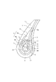
以下、図面を参照して、本発明を詳細に説明する。図3は、本発明に従う一実施形態の空気入りタイヤ(以下「タイヤ」という)のビード部をタイヤ幅方向断面図にて示している。このタイヤは、図3に示すようにビード部において、ビードコア1とビードコア1に沿ってタイヤ幅方向内側から外側に巻き回され、ビードコア1のタイヤ径方向外側面まで巻き付けられた巻き込み部2aを有するカーカス2とを備えたビード構造となっている。ビード部は、さらに、カーカス2の巻き込み部2aに沿って配置される底辺3と、底辺3に対向する頂点4で交わる内側斜辺5a及び外側斜辺5bとを有する断面三角形状をなすビードフィラ6を有している。
ビードフィラ6は、底辺3と底辺3に対向する頂点7で交わる内側斜辺8a及び外側斜辺8bを有する断面三角形状をなす硬ゴム部6aと、硬ゴム部6aの内側斜辺8a及び外側斜辺8bを覆う軟ゴム部6bとからなる。
頂点7における、軟ゴム部6bのタイヤ幅方向に対するタイヤ内側の厚さt1とタイヤ外側の厚さt2は、タイヤ外側の厚さt2の方が厚く設定されている。
また、図3に示すように、カーカス2には、補強材として、ワイヤチェーファ9、ナイロンチェーファ10、ゴムチェーファ11が順に巻きついている。
Hereinafter, the present invention will be described in detail with reference to the drawings. FIG. 3 is a cross-sectional view in the tire width direction of a bead portion of a pneumatic tire (hereinafter referred to as “tire”) according to an embodiment of the present invention. As shown in FIG. 3, the tire has a bead portion 1a wound around the
The
At the
Further, as shown in FIG. 3, a
このような構成によると、まず、従来のタイヤのビード部と同様に硬ゴムと軟ゴムを併用しているため、硬ゴムでビード部の剛性を上げ、操縦安定性を向上させつつ、軟ゴムで車両の乗り心地も向上させ、両者のバランスをとることで、操縦安定性と乗り心地を両立させることができる。 According to such a configuration, first, since hard rubber and soft rubber are used in the same manner as the bead portion of the conventional tire, the soft rubber increases the rigidity of the bead portion with hard rubber and improves the steering stability. By improving the ride comfort of the vehicle and balancing the two, it is possible to achieve both steering stability and ride comfort.
また、硬ゴム部6aが軟ゴム部6bに覆われた構造となっているため、タイヤ幅方向内側において、カーカス2は、ビードフィラ6の硬ゴム部6aとは直接的には接せず、軟ゴム部6bと接するため、ビードフィラ6とカーカス2との間の応力を緩和して、応力による歪みを緩和させて、セパレーションを防止し、ビード耐久性を向上させることができる。
In addition, since the
さらに、図3に示すように、頂点7における、軟ゴム部6bのタイヤ幅方向に対するタイヤ外側の厚さt2をタイヤ内側の厚さt1より厚くすることによって、歪みの影響の出やすいタイヤ外側における応力による歪みを効果的に防止することができる。
また、タイヤが外側に倒れこもうとする場合に、剛性の高い硬ゴム部6aがタイヤ内側に近いことにより、タイヤ外側への倒れこみを支える効果が高くなる。
Further, as shown in FIG. 3, at the
Further, when the tire is about to fall outside, the
さらにまた、図2に示すタイプのビード部を有する従来のタイヤでは、ゴムシートを新たな部材として使用しており、生産性の悪化やエア入りが懸念されるのに対し、本発明にかかる図3に示すビード部では新たな部材を必要としないため、かような欠点が改善される。 Furthermore, in the conventional tire having a bead portion of the type shown in FIG. 2, a rubber sheet is used as a new member, and there is a concern about the deterioration of productivity and the entry of air. Since the bead part shown in 3 does not require a new member, such a defect is improved.
また、図3ではカーカス2がビードコア1に巻き付いた構造を例に挙げているが、本発明はそれに限定されるものではなく、カーカス2がタイヤ幅方向内側から外側に折り返された構造の場合においても本発明の構造を採用できる。この場合は、図4に示すように、ビードコア1に沿ってタイヤ幅方向内側から外側に折り返される、折り返し部2bを有するカーカス2を備えたタイヤのビード部において、ビードフィラ6の底辺3がビードコア1のタイヤ径方向外面に沿って配置された構造となる点で、図3の場合の構造と異なるが、その他の点は同様である。
このようなカーカスが折り返された構造の場合も、同様の原理によって、操縦安定性と乗り心地を両立させ、歪みの影響の出やすいタイヤ外側における応力による歪みを効果的に防止し、タイヤ外側への倒れこみを支える効果が高め、生産性の悪化やエア入りを回避することができる。
Further, in FIG. 3, the structure in which the
In the case of such a folded carcass structure, the same principle is used to achieve both steering stability and ride comfort, effectively preventing distortion due to stress on the outside of the tire that is susceptible to distortion, and to the outside of the tire. The effect of supporting the fall of the product is enhanced, and it is possible to avoid the deterioration of productivity and the entry of air.
ところで本発明において、硬ゴム部6aは、図3及び図4に示すように外側斜辺8bが三角形状の内部に凸に屈折した形状をなしている。
Incidentally, in the present invention, the
また、図3のカーカスが巻き込み部を有するタイプの構造の場合、硬ゴム部6aは、底辺3が巻き込み部2aに該巻き込み部2aの端部まで沿って延び、該端部付近において、底辺3は屈折し、ビードコア1に直接接する形状である。
同様に図4のカーカスが折り返し部を有するタイプの構造の場合、硬ゴム部6aは、底辺3がビードコア1のタイヤ径方向外側面におけるタイヤ幅方向内側の端部まで沿って延び、該端部付近において、底辺3は屈折し、ビードコア1に直接接する形状である。
Further, in the case of the type of structure in which the carcass of FIG. 3 has a winding portion, the
Similarly, in the case of the structure in which the carcass of FIG. 4 has a folded portion, the
なお、硬ゴムと軟ゴムの2種類のゴムを用いたビードフィラを形成するためには、シングルチューバーを2台組み合わせた複合押出機である、デュアルチューバーを用いることができる。 In order to form a bead filler using two types of rubber, hard rubber and soft rubber, a dual tuber, which is a composite extruder combining two single tubers, can be used.
次に、従来技術のタイヤと本発明のタイヤでビード剛性及びビード耐久性に差があることを確認するための試験を行った。
発明例1として、図3に示すタイプのタイヤ、すなわち、カーカスが巻き込み部を有するタイプのビード構造で、ビードフィラの軟ゴム部をV字型にして、軟ゴム部が断面三角形状の硬ゴム部覆うようにし、さらに、図3の頂点7における軟ゴム部のタイヤ幅方向に対するタイヤ外側の厚さt2をタイヤ内側の厚さt1より厚くしたタイヤを試作した。また、発明例2として、図4に示すタイプのタイヤ、すなわち、カーカスがタイヤ幅方向内側から外側に折り返された構造で、軟ゴムのビードフィラをV字型にして、軟ゴム部が断面三角形状の硬ゴム部を覆うようにし、さらに、図4の頂点7における軟ゴム部のタイヤ幅方向に対するタイヤ外側の厚さt2をタイヤ内側の厚さt1より厚くしたタイヤを試作した。
比較例1として、図2に示すタイプのタイヤ、すなわち、硬ゴムのタイヤ幅方向外側に軟ゴム、内側にゴムシートを埋設したタイヤを試作した。また、比較例2として、図1に示すタイプのタイヤ、すなわち、硬ゴムのタイヤ幅方向外側に軟ゴムを埋設したタイヤを試作した。
Next, a test was performed to confirm that there is a difference in bead rigidity and bead durability between the tire of the prior art and the tire of the present invention.
Inventive example 1 is a tire of the type shown in FIG. 3, that is, a bead structure in which the carcass has a entangled portion, the bead filler has a V-shaped soft rubber portion, and the soft rubber portion has a triangular cross section. Further, a tire was manufactured as a trial in which the thickness t2 on the tire outer side in the tire width direction of the soft rubber portion at the
As Comparative Example 1, a tire of the type shown in FIG. 2, that is, a tire in which soft rubber is embedded on the outer side in the tire width direction of the hard rubber and a rubber sheet is embedded on the inner side, was manufactured. Further, as Comparative Example 2, a tire of the type shown in FIG. 1, that is, a tire in which soft rubber was embedded on the outer side in the tire width direction of a hard rubber was prototyped.
ビード剛性及びビード耐久性を向上したタイヤを製造して、市場に提供できる。 Tires with improved bead rigidity and bead durability can be manufactured and provided to the market.
1 ビードコア
2 カーカス
2a 巻き込み部
2b 折り返し部
3 底辺
4 頂点
5a 内側斜辺
5b 外側斜辺
6 ビードフィラ
6a 硬ゴム部
6b 軟ゴム部
7 硬ゴム部の頂点
8a 硬ゴム部の内側斜辺
8b 硬ゴム部の外側斜辺
9 ワーヤチェーファ
10 ナイロンチェーファ
11 ゴムチェーファ
12 サイドウォール
A 応力集中点
B ゴムシート
C エア
D 屈折点
E 屈折点
t1 硬ゴム部の頂点におけるタイヤ幅方向内側の厚さ
t2 硬ゴム部の頂点におけるタイヤ幅方向外側の厚さ
t3 屈折点Dにおけるタイヤ幅方向内側の厚さ
t4 屈折点Dにおけるタイヤ幅方向外側の厚さ
1 Bead core
2 Carcass
2a Entrainment part
2b Folding part
3 Bottom
4 vertex
5a Inner hypotenuse
5b Outside hypotenuse
6 Bead Filler
6a Hard rubber part
6b Soft rubber part
7 Top of hard rubber part
8a Inside hypotenuse of hard rubber part
8b Outside hypotenuse of hard rubber part
9 Wayachefa
10 Nylon chafer
11 Rubber chafer
12 sidewall
A Stress concentration point
B Rubber sheet
C Air
D Refraction point
E Refraction point
t1 Thickness inside tire width direction at top of hard rubber part
t2 Thickness on the outer side in the tire width direction at the top of the hard rubber part
t3 Thickness inside tire width direction at refraction point D
t4 Thickness outside the tire width direction at refraction point D
Claims (3)
前記ビードフィラは、タイヤ幅方向断面において、底辺が前記巻き込み部に沿って配置され、該底辺に対向する頂点がタイヤ径方向外方にある三角形状の硬質のゴム部と、タイヤ幅方向断面において該硬質のゴム部の前記底辺に隣接する2つの辺を覆う軟質のゴム部とからなり、
前記硬質のゴム部は、タイヤ幅方向断面において、前記底辺のタイヤ幅方向最外側点と前記頂点とを結ぶ外側斜辺が三角形状の内部に凸に屈折した形状をなしており、
前記硬質のゴム部は、タイヤ幅方向断面において、前記底辺が前記巻き込み部の端部まで沿って延び、該端部よりもタイヤ幅方向内側において屈折して前記ビードコアに直接接する形状をなしている、空気入りタイヤ。 A carcass body portion straddling a pair of bead cores in a toroidal shape, and a winding portion wound from the carcass body portion along the bead core from the inner side to the outer side in the tire width direction and at least wound to the outer side surface in the tire radial direction of the bead core. A pneumatic tire having a bead filler having a triangular cross section in the tire width direction on the outer side in the tire radial direction of the bead core,
The bead filler has a triangular hard rubber portion whose bottom is disposed along the entangled portion in the tire width direction cross section, and whose apex opposite to the bottom is radially outward of the tire, and in the tire width direction cross section, It consists of a soft rubber part covering two sides adjacent to the bottom side of the hard rubber part,
In the tire width direction cross section, the hard rubber portion has a shape in which an outer oblique side connecting the outermost point in the tire width direction of the bottom side and the apex is refracted into a triangular shape ,
In the tire width direction cross section, the hard rubber portion has a shape in which the base extends along the end of the entrainment portion and is refracted on the inner side in the tire width direction than the end to directly contact the bead core . , Pneumatic tires.
前記ビードフィラは、タイヤ幅方向断面において、底辺が前記ビードコアのタイヤ径方向外面に沿って配置され、該底辺に対向する頂点がタイヤ径方向外方にある三角形状の硬質のゴム部と、タイヤ幅方向断面において該硬質のゴム部の前記底辺に隣接する2つの辺を覆う軟質のゴム部とからなり、
前記硬質のゴム部は、タイヤ幅方向断面において、前記底辺のタイヤ幅方向最外側点と前記頂点とを結ぶ外側斜辺が三角形状の内部に凸に屈折した形状をなしており、
前記硬質のゴム部は、タイヤ幅方向断面において、前記底辺が前記ビードコアの前記タイヤ径方向外面におけるタイヤ幅方向内側の端部まで沿って延び、該端部よりもタイヤ幅方向内側において屈折して前記ビードコアに直接接する形状をなしている、空気入りタイヤ。 A carcass body portion straddling between a pair of bead cores in a toroidal shape, and a carcass having a turn-up portion that is folded back from the carcass body portion along the bead core from the inside in the tire width direction to the outside. A pneumatic tire having a bead filler having a triangular cross section in the width direction,
The bead filler, in a tire width direction cross section, a bottom is disposed along the tire radial outer surface of the bead core, and a triangular hard rubber portion whose apex facing the bottom is outward in the tire radial direction, and a tire width It consists of a soft rubber part covering two sides adjacent to the bottom side of the hard rubber part in the direction cross section,
In the tire width direction cross section, the hard rubber portion has a shape in which an outer oblique side connecting the outermost point in the tire width direction of the bottom side and the apex is refracted into a triangular shape ,
In the tire width direction cross section, the hard rubber portion extends along the tire width direction inner end of the bead core on the tire radial direction outer surface, and is refracted on the inner side in the tire width direction from the end. A pneumatic tire having a shape in direct contact with the bead core .
Priority Applications (1)
| Application Number | Priority Date | Filing Date | Title |
|---|---|---|---|
| JP2011033950A JP5771408B2 (en) | 2011-02-18 | 2011-02-18 | Pneumatic tire |
Applications Claiming Priority (1)
| Application Number | Priority Date | Filing Date | Title |
|---|---|---|---|
| JP2011033950A JP5771408B2 (en) | 2011-02-18 | 2011-02-18 | Pneumatic tire |
Publications (2)
| Publication Number | Publication Date |
|---|---|
| JP2012171432A JP2012171432A (en) | 2012-09-10 |
| JP5771408B2 true JP5771408B2 (en) | 2015-08-26 |
Family
ID=46974732
Family Applications (1)
| Application Number | Title | Priority Date | Filing Date |
|---|---|---|---|
| JP2011033950A Expired - Fee Related JP5771408B2 (en) | 2011-02-18 | 2011-02-18 | Pneumatic tire |
Country Status (1)
| Country | Link |
|---|---|
| JP (1) | JP5771408B2 (en) |
Family Cites Families (8)
| Publication number | Priority date | Publication date | Assignee | Title |
|---|---|---|---|---|
| JPH03248903A (en) * | 1990-02-26 | 1991-11-06 | Sumitomo Rubber Ind Ltd | Pneumatic tire |
| JPH0411505A (en) * | 1990-04-30 | 1992-01-16 | Sumitomo Rubber Ind Ltd | Pneumatic tire |
| JP3062324B2 (en) * | 1991-11-20 | 2000-07-10 | オーツタイヤ株式会社 | Pneumatic radial tire |
| JPH07149117A (en) * | 1993-11-30 | 1995-06-13 | Toyo Tire & Rubber Co Ltd | Pneumatic tire |
| JP3117645B2 (en) * | 1996-09-03 | 2000-12-18 | 株式会社ブリヂストン | Pneumatic radial tire |
| JP2000142040A (en) * | 1998-11-10 | 2000-05-23 | Yokohama Rubber Co Ltd:The | Pneumatic tire |
| JP2001018619A (en) * | 1999-07-02 | 2001-01-23 | Bridgestone Corp | Pneumatic tire excellent in bead part durability |
| JP3996422B2 (en) * | 2002-04-01 | 2007-10-24 | 住友ゴム工業株式会社 | Pneumatic tire |
-
2011
- 2011-02-18 JP JP2011033950A patent/JP5771408B2/en not_active Expired - Fee Related
Also Published As
| Publication number | Publication date |
|---|---|
| JP2012171432A (en) | 2012-09-10 |
Similar Documents
| Publication | Publication Date | Title |
|---|---|---|
| JP6249518B2 (en) | Pneumatic tire | |
| JP2015217824A (en) | Pneumatic tire | |
| JP2012162204A (en) | Pneumatic tire and method for manufacturing bead core | |
| JP2010137812A (en) | Pneumatic tire | |
| JP2008279796A (en) | Pneumatic tire | |
| JP2009056944A (en) | Pneumatic radial tire | |
| JP6363904B2 (en) | Tires for motorcycles | |
| JP7117267B2 (en) | tire | |
| JP5771408B2 (en) | Pneumatic tire | |
| JP2013244929A (en) | Tire | |
| JP5228866B2 (en) | Pneumatic tire | |
| JP5693013B2 (en) | Pneumatic radial tire | |
| JP5092929B2 (en) | Pneumatic bias tire for racing cart | |
| JP6042605B2 (en) | Pneumatic tire | |
| JP2010064644A (en) | Pneumatic radial tire | |
| JP2017056890A (en) | Pneumatic tire | |
| JP6138662B2 (en) | Pneumatic tire | |
| JP5844113B2 (en) | Pneumatic radial tire | |
| JP7165497B2 (en) | pneumatic tire | |
| JP2010215017A (en) | Pneumatic tire | |
| JP6078980B2 (en) | Pneumatic tire | |
| JP7387365B2 (en) | pneumatic tires | |
| JP6153852B2 (en) | Pneumatic tire | |
| JP2007210566A (en) | Pneumatic run-flat radial tire | |
| JP2017137008A (en) | Pneumatic tire |
Legal Events
| Date | Code | Title | Description |
|---|---|---|---|
| A621 | Written request for application examination |
Free format text: JAPANESE INTERMEDIATE CODE: A621 Effective date: 20140127 |
|
| A977 | Report on retrieval |
Free format text: JAPANESE INTERMEDIATE CODE: A971007 Effective date: 20140917 |
|
| A131 | Notification of reasons for refusal |
Free format text: JAPANESE INTERMEDIATE CODE: A131 Effective date: 20140930 |
|
| A521 | Request for written amendment filed |
Free format text: JAPANESE INTERMEDIATE CODE: A523 Effective date: 20141201 |
|
| A131 | Notification of reasons for refusal |
Free format text: JAPANESE INTERMEDIATE CODE: A131 Effective date: 20150303 |
|
| A521 | Request for written amendment filed |
Free format text: JAPANESE INTERMEDIATE CODE: A523 Effective date: 20150407 |
|
| TRDD | Decision of grant or rejection written | ||
| A01 | Written decision to grant a patent or to grant a registration (utility model) |
Free format text: JAPANESE INTERMEDIATE CODE: A01 Effective date: 20150602 |
|
| A61 | First payment of annual fees (during grant procedure) |
Free format text: JAPANESE INTERMEDIATE CODE: A61 Effective date: 20150629 |
|
| R150 | Certificate of patent or registration of utility model |
Ref document number: 5771408 Country of ref document: JP Free format text: JAPANESE INTERMEDIATE CODE: R150 |
|
| R250 | Receipt of annual fees |
Free format text: JAPANESE INTERMEDIATE CODE: R250 |
|
| R250 | Receipt of annual fees |
Free format text: JAPANESE INTERMEDIATE CODE: R250 |
|
| R250 | Receipt of annual fees |
Free format text: JAPANESE INTERMEDIATE CODE: R250 |
|
| LAPS | Cancellation because of no payment of annual fees |