JP5771292B2 - Impact indicator - Google Patents
Impact indicator Download PDFInfo
- Publication number
- JP5771292B2 JP5771292B2 JP2013557891A JP2013557891A JP5771292B2 JP 5771292 B2 JP5771292 B2 JP 5771292B2 JP 2013557891 A JP2013557891 A JP 2013557891A JP 2013557891 A JP2013557891 A JP 2013557891A JP 5771292 B2 JP5771292 B2 JP 5771292B2
- Authority
- JP
- Japan
- Prior art keywords
- mass member
- housing
- spring
- response
- impact
- Prior art date
- Legal status (The legal status is an assumption and is not a legal conclusion. Google has not performed a legal analysis and makes no representation as to the accuracy of the status listed.)
- Active
Links
Images


Classifications
-
- G—PHYSICS
- G01—MEASURING; TESTING
- G01L—MEASURING FORCE, STRESS, TORQUE, WORK, MECHANICAL POWER, MECHANICAL EFFICIENCY, OR FLUID PRESSURE
- G01L5/00—Apparatus for, or methods of, measuring force, work, mechanical power, or torque, specially adapted for specific purposes
- G01L5/0052—Apparatus for, or methods of, measuring force, work, mechanical power, or torque, specially adapted for specific purposes measuring forces due to impact
-
- G—PHYSICS
- G01—MEASURING; TESTING
- G01P—MEASURING LINEAR OR ANGULAR SPEED, ACCELERATION, DECELERATION, OR SHOCK; INDICATING PRESENCE, ABSENCE, OR DIRECTION, OF MOVEMENT
- G01P15/00—Measuring acceleration; Measuring deceleration; Measuring shock, i.e. sudden change of acceleration
- G01P15/02—Measuring acceleration; Measuring deceleration; Measuring shock, i.e. sudden change of acceleration by making use of inertia forces using solid seismic masses
- G01P15/03—Measuring acceleration; Measuring deceleration; Measuring shock, i.e. sudden change of acceleration by making use of inertia forces using solid seismic masses by using non-electrical means
- G01P15/032—Measuring acceleration; Measuring deceleration; Measuring shock, i.e. sudden change of acceleration by making use of inertia forces using solid seismic masses by using non-electrical means by measuring the displacement of a movable inertial mass
- G01P15/036—Measuring acceleration; Measuring deceleration; Measuring shock, i.e. sudden change of acceleration by making use of inertia forces using solid seismic masses by using non-electrical means by measuring the displacement of a movable inertial mass for indicating predetermined acceleration values
-
- H—ELECTRICITY
- H01—ELECTRIC ELEMENTS
- H01H—ELECTRIC SWITCHES; RELAYS; SELECTORS; EMERGENCY PROTECTIVE DEVICES
- H01H35/00—Switches operated by change of a physical condition
- H01H35/14—Switches operated by change of acceleration, e.g. by shock or vibration, inertia switch
-
- G—PHYSICS
- G01—MEASURING; TESTING
- G01L—MEASURING FORCE, STRESS, TORQUE, WORK, MECHANICAL POWER, MECHANICAL EFFICIENCY, OR FLUID PRESSURE
- G01L23/00—Devices or apparatus for measuring or indicating or recording rapid changes, such as oscillations, in the pressure of steam, gas, or liquid; Indicators for determining work or energy of steam, internal-combustion, or other fluid-pressure engines from the condition of the working fluid
-
- G—PHYSICS
- G01—MEASURING; TESTING
- G01L—MEASURING FORCE, STRESS, TORQUE, WORK, MECHANICAL POWER, MECHANICAL EFFICIENCY, OR FLUID PRESSURE
- G01L5/00—Apparatus for, or methods of, measuring force, work, mechanical power, or torque, specially adapted for specific purposes
-
- G—PHYSICS
- G01—MEASURING; TESTING
- G01N—INVESTIGATING OR ANALYSING MATERIALS BY DETERMINING THEIR CHEMICAL OR PHYSICAL PROPERTIES
- G01N3/00—Investigating strength properties of solid materials by application of mechanical stress
- G01N3/30—Investigating strength properties of solid materials by application of mechanical stress by applying a single impulsive force, e.g. by falling weight
-
- G—PHYSICS
- G01—MEASURING; TESTING
- G01P—MEASURING LINEAR OR ANGULAR SPEED, ACCELERATION, DECELERATION, OR SHOCK; INDICATING PRESENCE, ABSENCE, OR DIRECTION, OF MOVEMENT
- G01P15/00—Measuring acceleration; Measuring deceleration; Measuring shock, i.e. sudden change of acceleration
-
- G—PHYSICS
- G01—MEASURING; TESTING
- G01P—MEASURING LINEAR OR ANGULAR SPEED, ACCELERATION, DECELERATION, OR SHOCK; INDICATING PRESENCE, ABSENCE, OR DIRECTION, OF MOVEMENT
- G01P15/00—Measuring acceleration; Measuring deceleration; Measuring shock, i.e. sudden change of acceleration
- G01P15/02—Measuring acceleration; Measuring deceleration; Measuring shock, i.e. sudden change of acceleration by making use of inertia forces using solid seismic masses
- G01P15/03—Measuring acceleration; Measuring deceleration; Measuring shock, i.e. sudden change of acceleration by making use of inertia forces using solid seismic masses by using non-electrical means
-
- G—PHYSICS
- G01—MEASURING; TESTING
- G01P—MEASURING LINEAR OR ANGULAR SPEED, ACCELERATION, DECELERATION, OR SHOCK; INDICATING PRESENCE, ABSENCE, OR DIRECTION, OF MOVEMENT
- G01P15/00—Measuring acceleration; Measuring deceleration; Measuring shock, i.e. sudden change of acceleration
- G01P15/02—Measuring acceleration; Measuring deceleration; Measuring shock, i.e. sudden change of acceleration by making use of inertia forces using solid seismic masses
- G01P15/04—Measuring acceleration; Measuring deceleration; Measuring shock, i.e. sudden change of acceleration by making use of inertia forces using solid seismic masses for indicating maximum value
-
- H—ELECTRICITY
- H01—ELECTRIC ELEMENTS
- H01H—ELECTRIC SWITCHES; RELAYS; SELECTORS; EMERGENCY PROTECTIVE DEVICES
- H01H9/00—Details of switching devices, not covered by groups H01H1/00 - H01H7/00
- H01H9/16—Indicators for switching condition, e.g. "on" or "off"
Description
多くのタイプの物体は、物体の繊細さまたは脆弱性のため、製造、貯蔵、または運送中に監視する必要がある。たとえば、いくつかのタイプの物体は、落下した場合、または著しい衝撃を受けた場合、損傷を受けやすいことがある。したがって、品質管理の目的および/または輸送状態の一般的な監視のため、物体が露出されている環境状態を判定および/または検証することが望ましい。 Many types of objects need to be monitored during manufacturing, storage, or transportation because of the delicacy or fragility of the object. For example, some types of objects may be susceptible to damage when dropped or when subjected to significant impact. Therefore, it is desirable to determine and / or verify the environmental conditions to which objects are exposed for quality control purposes and / or general monitoring of transport conditions.
本開示の一態様によれば、衝撃検出のためのデバイスおよび技法が開示される。衝撃表示器は、筐体と、筐体内に位置する質量部材であって、筐体が加速イベントを受けたことに応答して、筐体内で質量部材を第1の位置から第2の位置へ移動することが可能となるように筐体が構成される、質量部材と、筐体内に配置され、質量部材を第1の位置へ付勢するように構成された第1および第2のばね部材とを含む。筐体が加速イベントを受けたことに応答して、質量部材が、第1のばね部材の付勢力に打ち勝ち、第1の位置から第2の位置へ移動するように構成され、第1および第2のばね部材はそれぞれ、質量部材の中央部分を横切って延びる。 According to one aspect of the present disclosure, devices and techniques for impact detection are disclosed. The impact indicator is a housing and a mass member located in the housing, and the mass member is moved from the first position to the second position in the housing in response to the housing receiving an acceleration event. A mass member configured to allow movement and a first and second spring member disposed within the housing and configured to bias the mass member to a first position Including. In response to the housing receiving an acceleration event, the mass member is configured to overcome the biasing force of the first spring member and move from the first position to the second position, the first and first Each of the two spring members extends across a central portion of the mass member.
本開示の別の実施形態によれば、衝撃表示器は、筐体と、筐体内に位置する質量部材であって、筐体内の質量部材の移動のための平行移動経路を形成する複数の側壁を筐体が備える、質量部材と、側壁上のそれぞれの座部位置に位置する端部を有する少なくとも1つのばね部材であって、質量部材を筐体内の第1の位置で保持するばね部材とを含む。筐体が加速イベントを受けたことに応答して、質量部材が筐体内で第1の位置から第2の位置へ移動するように構成され、ばね部材の端部は、座部位置から引き出され、質量部材が第1の位置に再設置されるのを防止する。 According to another embodiment of the present disclosure, an impact indicator is a housing and a plurality of side walls that form a translation path for movement of the mass member in the housing, the mass member being located in the housing A mass member, and at least one spring member having an end located at each seat position on the side wall, the spring member holding the mass member at a first position in the housing including. In response to the housing receiving an acceleration event, the mass member is configured to move from the first position to the second position within the housing, and the end of the spring member is pulled out of the seat position. , Preventing the mass member from being re-installed in the first position.
本開示のさらに別の実施形態によれば、衝撃表示器は、筐体と、筐体内に位置する質量部材であって、筐体が加速イベントを受けたことに応答して質量部材を移動することが可能となるように筐体が構成される、質量部材と、質量部材を非活動位置へ付勢するように構成された第1および第2のばね部材とを含む。筐体が第1の方向の第1の加速イベントを受けたことに応答して、質量部材が、付勢に打ち勝ち、非活動位置から第1の活動位置へ移動するように構成され、筐体が第1の方向とは反対の第2の方向の第2の加速イベントを受けたことに応答して、質量部材を第1の活動位置から第2の活動位置へ移動させるように第1および第2のばね部材が構成される。 According to yet another embodiment of the present disclosure, an impact indicator is a housing and a mass member located within the housing, the mass indicator moving in response to the housing receiving an acceleration event. A mass member configured to allow the mass member and first and second spring members configured to bias the mass member to an inactive position. In response to the housing receiving a first acceleration event in a first direction, the mass member is configured to overcome the bias and move from the inactive position to the first active position. In response to receiving a second acceleration event in a second direction opposite to the first direction to move the mass member from the first active position to the second active position. A second spring member is configured.
本出願、本出願の目的および利点をより完全に理解するために、添付の図面と併せて以下の説明を次に参照する。 For a more complete understanding of the present application, the objects and advantages of the present application, reference is now made to the following description, taken in conjunction with the accompanying drawings, in which:
本開示の実施形態は、衝撃検出および表示のためのデバイスおよび技法を提供する。一実施形態によれば、衝撃表示器は、筐体と、筐体内に位置する質量部材であって、筐体が、筐体が加速イベントを受けたことに応答して筐体内で質量部材を第1の位置から第2の位置へ移動させるように構成される、質量部材と、筐体内に配置され、質量部材を第1の位置へ付勢するように構成された第1および第2のばね部材とを含む。筐体が加速イベントを受けたことに応答して、質量部材は、第1のばね部材の付勢力に打ち勝ち、第1の位置から第2の位置へ移動するように構成され、第1および第2のばね部材はそれぞれ、質量部材の中央部分を横切って延びる。本開示の実施形態は、衝撃および/または加速イベントの検出を可能にしながら、所定のレベルまたは大きさの衝撃が発生した後は衝撃表示器10の状態の再設定を防止または実質上防止する。たとえば、いくつかの実施形態では、表示器10の質量部材30は、加速イベントに応答して非活動位置から活動位置へ移動するように構成される。表示器10が、表示器10を非活動状態に再設定しようとして生じうる加速イベント(たとえば、質量部材30を逆方向へ移動させるのに十分なレベルまたは大きさ)を受けた場合、質量部材30は、ある活動位置から別の活動位置へ移動する。
Embodiments of the present disclosure provide devices and techniques for impact detection and display. According to one embodiment, the impact indicator is a housing and a mass member located within the housing, the housing displaying the mass member within the housing in response to the housing receiving an acceleration event. A mass member configured to move from the first position to the second position, and a first and second configured in the housing and configured to bias the mass member to the first position A spring member. In response to the housing receiving an acceleration event, the mass member is configured to overcome the biasing force of the first spring member and move from the first position to the second position, the first and first Each of the two spring members extends across a central portion of the mass member. Embodiments of the present disclosure prevent or substantially prevent resetting the state of the
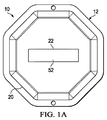
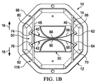
次に図を参照し、特に図1Aおよび図1Bを参照すると、本開示の例示的な実施形態を実施できる衝撃表示器10の例示的な図が提供されている。図1Aは衝撃表示器10の正面図を示す図であり、図1Bは衝撃表示器10の背面図を示す図である。図1Aおよび図1Bでは、表示器10は、物体を収容する輸送コンテナに添付されるように、またはその輸送コンテナ内に配置されるように構成された携帯型のデバイスであり、この物体に関連する衝撃および/または加速イベントが監視される。衝撃表示器10の実施形態は、物体が物体の製造、貯蔵、および/または輸送中に衝撃または何らかのレベルの加速イベントに露出されたかどうかを監視する。いくつかの実施形態では、衝撃表示器10は、たとえば接着材料、永久的もしくは一時的な留め具、または様々な異なるタイプの取付けデバイスを使用して、輸送コンテナに添付することができる。輸送コンテナは、監視される物体が緩く配置されているコンテナを含むことができ、または監視される物体自体のコンテナを構成することができる。図1Aおよび図1Bは単なる例示であり、異なる実施形態を実施できる環境に関していかなる限定も主張または示唆しようとするものではないことを理解されたい。
With reference now to the figures and in particular with reference to FIGS. 1A and 1B, an exemplary illustration of an
図1Aおよび図1Bに示す実施形態では、衝撃表示器10は筐体12を備え、筐体12内には検出アセンブリ14が配置される。図示の実施形態では、検出アセンブリ14は、図1Bで表示器10に対して方向16または方向18で示す2つの異なる方向(すなわち、方向16/18、または対応する方向16/18の方向ベクトル成分を有する検出アセンブリ14に対する角度)のいずれかで、衝撃または加速イベントを検出および表示するように構成される。しかし、アセンブリ14は、単一の方向に対応する衝撃イベントを検出/表示するように構成できることを理解されたい(以下でさらに説明)。さらに、表示器10内には、追加の方向の衝撃検出/表示を提供するために、追加の検出アセンブリ14を含むこともできることを理解されたい。
In the embodiment shown in FIGS. 1A and 1B, the
いくつかの実施形態では、筐体12は、透明または半透明の材料から構成および/または構築され、この材料の前面側にはマスキングラベル20が位置し、または材料に添付されている(図1A)。いくつかの実施形態では、マスキングラベル20は、衝撃検出の視覚的な表示を提供するための1つまたは複数の開口または「窓」22を有するように構成される。たとえば、以下でさらに説明するように、表示器10が何らかの所定のレベルの衝撃または加速イベントを被り、または受けたことに応答して、検出アセンブリ14は、1つもしくは複数の窓22の中に、または1つもしくは複数の窓22を通じて、視覚的な表示を表させて、監視される物体が何らかのレベルの衝撃を被り、または被った可能性があるという視覚的な表示を提供する。しかし、他の方法を使用して、検出アセンブリ14が活動状態へ移動し、かつ/または別の方法で活動状態になったという視覚的な表示を提供し、表示器10が振動、衝撃、または加速イベントを経験したことを表示することもできることを理解されたい。また、筐体12は、他の材料(たとえば、1つまたは複数の窓22が形成された不透明の材料)から構成および/または製造できることも理解されたい。
In some embodiments, the
図1Bを参照すると、検出アセンブリ14を非活動状態または最初の検出前状態(すなわち、加速イベントを被る前)で示す。図示の実施形態では、検出アセンブリ14は、重量または質量部材30と、ばね部材40および42とを備える。筐体12は、質量部材30の両側に位置する側壁46および48を備える。側壁46および48は、筐体12または表示器10が加速イベントを被ったことに応答して筐体12内で質量部材30の移動を可能にする平行移動経路を形成する。たとえば、図1Bでは、質量部材30は、筐体12内の非活動位置50に位置する。さらに、図1Aを参照すると、質量部材30の中央表面部分52が窓22内に位置し、かつ/または別の方法で窓22内に見える。
Referring to FIG. 1B, the
図1Bに示す実施形態では、ばね部材40および42は、表示器10の検出前状態で、質量部材30を非活動位置50へ付勢する。たとえば、図示の実施形態では、ばね部材40および42は、それぞれ板ばね56および58を構成するが、他のタイプの付勢要素も使用できることを理解されたい。図1Bでは、側壁46内に、板ばね56および58のそれぞれの端部68および70を保持するための凹部または座部62および64が形成されている。側壁48内には、板ばね56および58のそれぞれの端部80および82を保持するための凹部または座部74および76が形成されている。板ばね56および58は、質量部材30の幅より長い長さを有するように形成される(たとえば、側壁46から側壁48の方向に測定される)。板ばね56の端部68および80は、板ばね56が質量部材30の移動経路を横切る向きに位置決めされるように、それぞれの座部62および74内に位置する。板ばね58の端部70および82は、板ばね58が質量部材30の移動経路を横切る向きに位置決めされるように、それぞれの座部64および76内に位置する。たとえば、側壁46および48によって形成される平行移動経路は、16および18で示す方向に質量部材30の移動を可能にする。
In the embodiment shown in FIG. 1B, the
板ばね56の端部68および80は、座部62および80内に位置し、板ばね58の端部70および82は、それぞれの座部64および76内に位置し、その結果、板ばね56および58は、互いに対向する凸状表面を有する。したがって、図示の実施形態では、板ばね56および58は、互いの方へ付勢されている。図1Bに示す実施形態では、板ばね56および58はそれぞれ、質量部材30の弧状に形成された対向する壁88と90との間で、質量部材30の中央部分を横切って横方向に延びる。板ばね56および58は、互いの方へ付勢され、質量部材30を非活動位置50で支持する(たとえば、板ばね56および58は、質量部材30を非活動位置50で保持するように、質量部材30のそれぞれの壁88および90に接触して支持する)。質量部材30は、別の方法で形成することもでき、かつ/またはばね部材40および42は、質量部材30を非活動位置50へ保持および/もしくは付勢するように、質量部材30に対して別の方法で構成および/もしくは位置決めすることができることを理解されたい。
Ends 68 and 80 of
図2Aおよび図2Bは、図1Aおよび図1Bに示す表示器10のそれぞれの前面図および背面図を活動状態で示す図である。図2Aおよび図2Bに示す実施形態では、表示器10および/または筐体12は、ばね部材40および42の付勢力に打ち勝ち、それによって質量部材30を非活動位置50から活動位置96へ移動させるレベルおよび/または大きさの、方向16に対応する方向の衝撃および/または加速イベントを被っている。加速イベントに応答して、板ばね56は反転し、板ばね56の凸状部分は、質量部材30の壁88に付勢力を加えて、質量部材30を活動位置96へ付勢する。さらに、加速イベントおよび活動位置96への質量部材30の移動に応答して、板ばね58の端部70および82は、それぞれの座部64および76から引き出される。図2Aに最もよく示すように、活動位置96では、質量部材30のうち、質量部材30が非活動位置50にあるときとは異なる部分が、窓22内に位置し、かつ/または別の方法で窓22内に見える。たとえば、非活動位置50では、質量部材30の中央部分(たとえば、中央表面部分52(図1A))が、窓22内に位置し、かつ/または別の方法で窓22内に見える。しかし、活動位置96への質量部材30の移動に応答して、中央表面部分52に隣接して位置する表面部分98が、窓22内に位置し、かつ/または別の方法で窓22内に見える。以下でさらに説明するように、質量部材30は、表示器10が特定のレベルまたは大きさの加速イベント/衝撃を被ったかどうかに関する表示を提供するために、質量部材30上の異なる位置で、質量部材30のうち窓22に面する側に、筐体12内の質量部材30の非活動位置および活動位置に対応する異なるタイプおよび/または形状の印を収容することができる。
2A and 2B are diagrams showing the front and rear views, respectively, of the
図3Aは、表示器10の図2Bの一部分の拡大図を示す図であり、図3Bは、表示器10の図3Aの一部分の拡大図を示す図である。上記の図2B、図3A、および図3Bを参照すると、ばね部材40および42の付勢力に打ち勝つレベルおよび/または大きさの方向16の加速イベントに応答して、板ばね56は反転し、板ばね56の凸状部分は、質量部材30の壁88に付勢力を加えて、質量部材30を活動位置96へ付勢する。さらに、板ばね58の端部70および82は、それぞれの座部64および76から引き出される。図3Aおよび図3Bに最もよく示すように、側壁46および48内にはそれぞれ窪み領域102および104が形成され、窪み領域102および104は、それぞれ側壁46および48の隣接する壁面106、108、110、および112から後退し、かつ/またはずれている。窪み領域102は、座部62と64との間で側壁46に沿って位置し、窪み領域104は、座部74と76との間で側壁48に沿って位置する。活動位置96への質量部材30の移動に応答して、板ばね58の端部70および82は、それぞれの座部64および76から引き出され、それぞれの窪み領域102および104内に位置決めされる。窪み領域102および104は、板ばね58の端部70および82がそれぞれの座部64および76へ復帰するのを防止または実質上防止する。したがって、表示器10が活動状態についた後、質量部材30を非活動位置50に再設定および/または再位置決めしようとして方向16とは反対の方向(たとえば、方向18)の別の加速イベントを被った場合、窪み領域102および104は、座部64および76への板ばね58の端部70および82の復帰に抵抗し、それによって方向16の追加の付勢力をもたらす。非活動位置50の方への質量部材30の移動を実現するには、この追加の付勢力に逆方向で打ち勝つ必要があるはずである。
3A is an enlarged view of a part of the
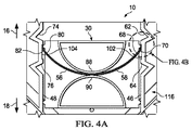
図4Aは、表示器10の一部分の拡大図を示す図であり、質量部材30は、別の活動位置116(たとえば、筐体12のうち、活動位置96の反対側)に位置し、図4Bは、図4Aの一部分の拡大図を示す図である。見やすいように、図1Bを参照すると、質量部材30は非活動位置50に示されている。図1Bでは活動位置96および116を参照し、活動位置96および116にあるときに質量部材30が位置する筐体12内の位置を示す。図4Aおよび図4Bを参照すると、表示器10が方向16の加速イベントを被り、それにより質量部材30を活動位置96(図2B)へ移動させ、その後、板ばね56および58によって加えられる力(複数可)に打ち勝つレベルおよび/または大きさの方向18の別の加速イベント(たとえば、質量部材30を非活動位置50に再設置しようとする無許可の試み、または何らかの他の衝撃イベントへの応答)を被った場合、板ばね56および58はどちらもつぶれ、または反転し、質量部材30は、活動位置96から非活動位置50を通って活動位置116へ移動する。たとえば、板ばね56および58によって加えられる力(複数可)に打ち勝つレベルおよび/または大きさの方向18の加速イベントに応答して、板ばね56および58はどちらもつぶれ、または反転し、その結果、板ばね56および58の凸状部分は、質量部材30の壁90に付勢力を加えて、質量部材30を活動位置116へ付勢する。さらに、板ばね56の端部68および80は、それぞれの座部62および74から引き出され、それぞれの窪み領域102および104内に位置決めされる。したがって、活動位置96から活動位置116への質量部材30の移動に応答して、板ばね56および58は、同じ方向に(たとえば、質量部材30の壁90の方へ)付勢され、それぞれの板ばね56および58の端部68、70、80、および82は、それぞれ窪み領域102および104内に位置して、板ばね56および58が座部62、64、74、または76へ復帰するのを防止または実質上防止し、それによって活動状態についた後に質量部材30が非活動位置50へ復帰する(維持された継続状態で)のをさらに防止または実質上防止する。
FIG. 4A shows an enlarged view of a portion of the
図5Aは、本開示による表示器10の別の実施形態を示す図であり、図5Bは、表示器10の図5Aの一部分の拡大図を示す図である。図5Aおよび図5Bに示す実施形態では、側壁46および48内にはそれぞれ、それぞれ追加のばね座部120および122が形成されている。座部120は、座部62と64との間で側壁46に沿って位置し、座部122は、座部74と76との間で側壁48に沿って位置する。座部62、64、74、および76と同様に、座部120および122は、表示器10が質量部材30の移動を引き起こすのに十分な大きさの衝撃または加速イベントを被ったことに応答して、それぞれの板ばね56および58の端部68/80および70/82を受け取るために、それぞれの側壁46および48に沿って凹状領域を備える(たとえば、図2A、図3A、図3B、図4A、および図4Bに関連して上述)。たとえば、図6は、図5Aおよび図5Bに示す表示器10を、質量部材30が活動位置96に位置する状態で示す図である。板ばね56および58は、質量部材30の移動のための平行移動経路の横方向の幅より長い長さを有するように構成されるため、板ばね56および58の端部は、側壁46と48との間で最も広い横方向の寸法を探し、そこで張力を解放する。したがって、たとえば、表示器10が板ばね56および58の付勢力に打ち勝つのに十分な大きさの方向16の加速イベントを被ったことに応答して、質量部材30は非活動位置50から活動位置96の方へ移動し、板ばね56はつぶれ、かつ/または反転し、質量部材30の壁88の方へ付勢力を加え、板ばね58の端部70および82は、それぞれの座部64および76から引き出されて、それぞれの座部120および122に位置する。座部120および122、102および104は、板ばね58の端部70および82がそれぞれの座部64および76へ復帰するのを防止または実質上防止する。したがって、表示器10が活動状態についた後、質量部材30を非活動位置50に再設定および/または再位置決めしようとして方向16とは反対の方向(たとえば、方向18)の別の加速イベントを被った場合、窪み領域102および104は、座部64および76への板ばね58の端部70および82の復帰に抵抗し、それによって方向16の追加の付勢力をもたらす。非活動位置50の方への質量部材30の移動を実現するには、この追加の付勢力に逆方向で打ち勝つ必要があるはずである。
FIG. 5A is a diagram illustrating another embodiment of a
図7Aは、図5A、図5B、および図6の表示器10の一部分の拡大図を示す図であり、質量部材30は、活動位置116に位置し、図7Bは、図7Aの一部分の拡大図を示す図である。表示器10が方向16の加速イベントを被り、それにより質量部材30を活動位置96(図6)へ移動させ、その後、板ばね56および58によって加えられる力(複数可)に打ち勝つレベルおよび/または大きさの方向18の別の加速イベント(たとえば、質量部材30を非活動位置50に再設置しようとする無許可の試み、または何らかの他の衝撃イベントへの応答)を被った場合、板ばね56および58はどちらもつぶれ、または反転し、質量部材30は、活動位置96から非活動位置50を通って活動位置116へ移動する。たとえば、板ばね56および58によって加えられる力(複数可)に打ち勝つレベルおよび/または大きさの方向18の加速イベントに応答して、板ばね56および58はどちらもつぶれ、または反転し、その結果、板ばね56および58の凸状部分は、質量部材30の壁90に付勢力を加えて、質量部材30を活動位置116へ付勢する。さらに、板ばね56の端部68および80は、それぞれの座部62および74から引き出され、それぞれの座部120および122内に位置決めされる。したがって、活動位置96から活動位置116への質量部材30の移動に応答して、板ばね56および58は、同じ方向に(たとえば、質量部材30の壁90の方へ)付勢され、それぞれの板ばね56および58の端部68、70、80、および82は、それぞれ座部120および122内に位置して、板ばね56および58が座部62、64、74、または76へ復帰するのを防止または実質上防止し、それによって活動状態についた後に質量部材30が非活動位置50へ復帰する(維持された継続状態で)のをさらに防止または実質上防止する。
FIG. 7A is an enlarged view of a portion of the
図8は、本開示の一実施形態による表示器10の質量部材30の一実施形態を示す図である。いくつかの実施形態では、質量部材30は、表示器10の活動化状態を表示するためのディスプレイ要素として機能する。たとえば、図8では、窓22(図1A)を通じて外側に面する質量部材30の表面130が示されている。図示の実施形態では、表面130は、非活動表面部分132と、活動表面部分134および136とを含む。表面部分132、134、および136はそれぞれ、表示器10の非活動状態または活動状態において、窓22を通じて視覚的に露出される異なる色、マーキング、または他のタイプの印を含むことができる。たとえば、非活動表面部分132は、質量部材30のうち、質量部材30が非活動位置50に位置するときに窓22を通じて見える表面部分を含む。活動表面部分136は、質量部材30のうち、質量部材30が活動位置96(たとえば、図2Aおよび図2B)に位置するときに窓22を通じて見える表面部分を含み、活動表面部分134は、質量部材30のうち、質量部材30が活動位置116(たとえば、図4Aおよび図4B)に位置するときに窓22を通じて見える表面部分を含む。いくつかの実施形態では、表面部分132、134、および136は、表示器10が非活動状態であるか、それとも活動状態(すなわち、表示器10が何らかの所定のレベルまたは大きさの衝撃または加速イベントを被ったことを表示する活動状態)であるかを視覚的に表示するカラー・コードを含む。たとえば、表面部分132は白色を含むことができ、表面部分134および136は赤色を含むことができる。したがって、非活動状態では、表面部分132の白色が窓22内に見えるはずである。活動状態では(受けた加速イベントの方向および/または数量に応じて)、表面部分134または136の1つに対応する赤色が窓22を通じて見えるはずである。この実施形態では、一例として単一の窓22(たとえば、質量部材30に対する非活動位置50に対応する位置に配置された単一の窓22)が使用されている。しかし、異なる窓の数量および/または配置を使用できることを理解されたい。たとえば、いくつかの実施形態では、2つの窓を利用することができ、各窓は、質量部材30の活動位置に対応する(たとえば、1つの窓は、質量部材30に対する活動位置96に対応する位置に位置し、別の窓は、質量部材30の活動位置116に対応する位置に位置する)。この例では、表面部分134および136のカラー・コーディングを省略することができる(たとえば、活動位置96または活動位置116に対応して窓を通じて見えるはずの表面部分132を赤色または他の所望の色にカラー・コーディングする)。
FIG. 8 is a diagram illustrating one embodiment of the
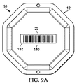
図8に示す実施形態では、表面部分132、134、および/または136は、表示器10の活動化または衝撃状態を表示するために、バーコードまたは他のタイプの印(たとえば、数字コード、英数字コード、もしくは他のタイプの符号化された印など)を含むことができる(たとえば、人間には知覚できないが機械には知覚できる、符号化できる状態識別子など)。たとえば、図示の実施形態では、表面部分132は、「SW087654321」というコード/印を表すバーコードの印140を含み、表面部分134および136は、「SW187654321」というコード/印をそれぞれ表すバーコードの印142および144を含む。いくつかの実施形態では、表面部分132、134、および136はそれぞれ、同じ色(または異なる色の省略)を含むことができる。バーコードの印140、142、および144は、製造者情報、シリアル番号情報、および状態情報に対応する情報を含むことができる。たとえば、図示の実施形態では、最初の2つの文字/桁を使用して、製造者または会社情報を識別することができ、第3の文字/桁を使用して、活動化状態を表示することができ、残りの文字/桁を使用して、シリアル番号情報を表示することができる。バーコードまたは他のタイプの符号化された印の様々な文字/桁は、異なるタイプの情報を表すように変更できることを理解されたい。いくつかの実施形態では、様々な文字/桁または他のタイプの符号化された印は、符号化された印によって表される情報のタイプおよび/または特有の詳細に関して、人間には知覚および/または解読できないものとすることができる。したがって、この例では、印140内の「0」という第3の文字/桁は非活動状態を表示し、印142および144内の「1」という第3の文字/桁は表示器10の活動状態を表示する。図9Aおよび図9Bは、表示器10の活動化状態を表示するバーコードの印140、142、および144の利用を示す図である。図8および図9Aを参照すると、非活動状態(たとえば、何らかの所定のレベルまたは大きさの衝撃/加速を被り、かつ/または経験する前)では、印140が窓22を通じて見える。図8および図9Bを参照すると、何らかの所定のレベルまたは大きさの衝撃/加速を受け、かつ/または被った後、印142または144が窓22を通じて見えるはずである。図9Bに示す実施形態では、方向16の加速イベントを受けたことに応答して、たとえば、印144が窓22内に見える。
In the embodiment shown in FIG. 8,
図10は、本開示の一実施形態による表示器10の質量部材30の別の実施形態を示す図である。図10では、窓22(図1A)を通じて外側に面する質量部材30の表面130が示されている。図10に示す実施形態では、表面部分132、134、および136はそれぞれ、表示器10の活動状態における衝撃/加速の方向の表示を提供するために、窓22を通じて視覚的に露出される異なる色、マーキング、または他のタイプの印を含むことができる。たとえば、表面部分132は白色を含むことができ、表面部分134は黄色を含むことができ、表面部分136は赤色を含むことができる。したがって、非活動状態では、表面部分132の白色が窓22内に見えるはずである。活動状態では、方向16の何らかの所定のレベルまたは大きさの衝撃/加速を受けたことに応答して、表面部分136の赤色が窓22を通じて見えるはずである。活動状態では、方向18の何らかの所定のレベルまたは大きさの衝撃/加速を受けたことに応答して、表面部分134の黄色が窓22を通じて見えるはずである。したがって図示の実施形態では、質量部材30は、表示器10の活動状態および/または受けた場合は衝撃の方向を表示するディスプレイ要素として機能する。したがって、表示器10は、衝撃イベントならびにその衝撃イベントの方向を表示するように構成することができる。
FIG. 10 is a diagram illustrating another embodiment of the
図10に示すように、表面部分132、134、および136はまた、衝撃イベントの方向を表示するために、バーコードまたは他のタイプの符号化された印を含むことができる(たとえば、人間には知覚/判読できないが機械には知覚/判読できる、符号化できる状態および/または方向識別子など)。たとえば、図示の実施形態では、表面部分132は、「SW087654321」というコード/印を表すバーコードの印150を含み、表面部分134は、「SW287654321」というコード/印を表すバーコードの印152を含み、表面部分136は、「SW187654321」というコード/印を表すバーコードの印154を含む。いくつかの実施形態では、表面部分132、134、および136はそれぞれ、同じ色(または異なる色の省略)を含むことができる。この実施形態では、第3の文字/桁を使用して、活動化の状態、および活動している場合、受けた衝撃の方向を表示する。たとえば、印150内の「0」という第3の文字/桁は、非活動状態を表示する。印154が窓22内に見える場合、印154内の「1」という第3の文字/桁は、表示器10の活動状態、および表示器10が方向16の加速イベントを受けたことを表示する。印152が窓22内に見える場合、印152内の「2」という第3の文字/桁は、表示器10の活動状態、および表示器10が方向18の加速イベントを受けたことを表示する。したがって、表示器10は、衝撃イベント状態と、受けた衝撃イベントの方向表示との両方を表示するように構成することができる。バーコードの印ではなく、英字、数字、英数字、または他のタイプの暗号化および/または符号化された印を使用して、衝撃イベント状態および/または受けた衝撃イベントの方向表示を表示することができ、その結果、印は人間が知覚できるが、鍵または他の復号情報がなければ、この印を容易に解読および/または判読できないことを理解されたい。たとえば、バーコード以外の形式の「SW087654321」などのコードの印を使用することができる。
As shown in FIG. 10,
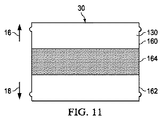
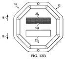
図11は、本開示による表示器10の質量部材30の別の実施形態を示す図であり、図12Aおよび図12Bは、表示器10の別の実施形態を示す図であり、図11に示す質量部材30の実施形態を利用する2つの状態窓22(窓221および222として識別)を有する。図11では、質量部材30の表面130は、非活動表面部分160および162と、活動表面部分164とを含む。表面部分160、162、および164は、表示器10の非活動状態または活動状態において、窓221および/または222を通じて視覚的に露出される異なる色、マーキング、または他のタイプの印を含むことができる。たとえば、活動表面部分164は、質量部材30のうち、質量部材30が活動位置96(図2Bおよび図11B)に位置するときに窓221を通じて見え、質量部材30が活動位置116(図4A)に位置するときに窓222を通じて見える表面部分を含む。非活動状態(たとえば、非活動位置50(図1B))では、表面部分160および162は、それぞれの窓221および222を通じて見える。したがって、図12Aを参照すると、活動化前、または何らかの所定のレベルもしくは大きさの加速イベントを被る前は、表面部分160および162が、それぞれの窓221および222を通じて見える。何らかの所定のレベルまたは大きさの加速イベントを受けたことに応答して、質量部材30の移動により、表面部分162が窓221または222の1つ(衝撃イベントの方向に応じる)を通じて見えるようになる。たとえば図12Bでは、方向16の衝撃イベントに応答して、表面部分164が、窓221を通じて見えるようになる。
FIG. 11 is a diagram illustrating another embodiment of the
したがって、表示器10は、異なるタイプの視覚的な活動化状態表示を提供するように、様々な形で構成することができる。たとえば、いくつかの実施形態では、窓(複数可)22を介して表示器10の状態の視覚的な表示を提供するために、色ベースのディスプレイ要素またはバーコードもしくは他のタイプの印を有するディスプレイ要素を、質量部材30とは別個に独立して提供することができる。たとえば、いくつかの実施形態では、ばね部材40および/または42は、表示器10の活動化に応答して窓(複数可)22内で摺動、移動、および/または別の方法で位置する質量部材30以外の別の要素に結合することができる。別の実施形態では、ばね部材40および/または42は、表示器10の活動化に応答して窓(複数可)22の領域内へ摺動、平行移動、または枢動するラッチ機構、枢動部材/要素、または他のタイプの構造にさらに結合することができる。さらに他の実施形態では、筐体12は、質量部材30がそれぞれの活動位置96および116内へ移動したことに応答して窓(複数可)22の領域内へ摺動、平行移動、または枢動する活動位置96および116の近傍に位置する1つまたは複数の表示器/ディスプレイ要素を含むことができる。表示器10はまた、表示器10の活動化に応答して窓(複数可)22内で視覚的な表示を引き起こすスイッチまたは他のタイプの電子モジュールを含むことができる。たとえば、いくつかの実施形態では、表示器10は、衝撃検出状態、衝撃の方向、および/または他のタイプ(複数可)の情報(たとえば、製造者、シリアル番号など)を表示する色、バーコード、または他のタイプの印もしくはコードを表すように窓(複数可)22内に位置決めされ、または別の方法で筐体12上に位置するスイッチ、電源、および液晶ディスプレイ(LCD)、または他のタイプの電子ディスプレイ要素を含むことができる。一例として、表示器10は、活動化位置96もしくはその付近に位置するスイッチ要素、および/または活動化位置116もしくはその付近に位置するスイッチ要素を含むことができ、質量部材30がスイッチ要素に接触したことに応答して、色、バーコード、または他のタイプの印もしくはコードがディスプレイユニット上で変更または表される。この例では、たとえばバーコードの印を使用して、ディスプレイユニットは、最初に1つのバーコードの印を表し、衝撃を検出したことに応答してこのバーコードの印を電子的に変化させることができる(衝撃の方向に基づいて異なるバーコードを含む)。したがって、様々な構造および/または方法を使用して衝撃検出および/または衝撃方向を表示できることを理解されたい。
Accordingly, the
たとえば図1A、図1B、図2A、および図2Bに示す実施形態では、2つのばね部材40および42を使用して、質量部材30を非活動状態または位置50で保持し(少なくとも最初)、衝撃イベントが表示器10の活動化を引き起こした後に質量部材30が非活動位置50に再設置されるのを防止する。しかし、ばね部材の数量はより多くてもより少なくてもよいことを理解されたい。たとえば、いくつかの実施形態では、表示器10は、単方向の質量部材30の移動(たとえば、方向16)向けに構成することができる。この実施形態では、たとえば、筐体12は、質量部材30が非活動位置50から活動位置96へのみ移動するように、質量部材30の追加の壁または増大させた長さを有するように構成することができる。この実施形態では、たとえば、ばね部材42が質量部材30を非活動位置で保持する一方、ばね部材40を省略することができる。ばね部材42の保持力に打ち勝つのに十分な大きさの方向16の加速イベントに応答して、質量部材30は活動位置96へ移動し、板ばね58の端部70および82は座部64および76から引き出されて窪み領域102および104(または座部120および122)に入り、その後、質量部材30を活動位置96に保持する。また、質量部材30の形状および/または構成は変動しうることを理解されたい。たとえば、壁88および90ではなく、質量部材30は、ばね部材40および42の1つまたは複数が力を加えることができる支持表面を提供するために、ポストまたは他のタイプの表面特徴を備えることができる。
For example, in the embodiment shown in FIGS. 1A, 1B, 2A, and 2B, two
いくつかの実施形態では、ばね部材40および/または42は、表示器10が所定のレベルもしくは大きさの衝撃/加速を経験するまで、および/または所定のレベルもしくは大きさの衝撃/加速を経験しない限り、質量部材30を特定の位置(たとえば、非活動位置50および/または活動位置96/116)で付勢し、かつ/または別の方法で保持するように、選択され、かつ/または別の方法で構成される。たとえば、衝撃表示器10は、質量部材30の特定の重量を設定すること、ばね部材40/42の特定の厚さおよび/または材料を選択/構成することなどによって、様々なレベルの衝撃または加速の活動化に対して構成することができる。たとえば、いくつかの実施形態では、ばね部材40/42は、所望の温度スペクトルにわたって実質上一定のばね張力を維持できるポリマー材料(たとえば、Duralar(登録商標)材料など)から構成することができ、それによって、普通なら温度変化に起因しうる表示器10の不注意による活動化を減少させることができる。
In some embodiments, the spring members 40 and / or 42 experience a predetermined level or magnitude of impact / acceleration until and / or until the
したがって、本開示の実施形態は、所定のレベルまたは大きさの衝撃が発生した後に衝撃表示器10の状態の再設定を防止または実質上防止しながら、衝撃および/または加速イベントの検出を可能にする。たとえば、いくつかの実施形態では、表示器10の質量部材30は、加速イベントに応答して非活動位置から活動位置へ移動するように構成される。表示器10が、表示器10を非活動状態へ再設定しようとして生じうる加速イベント(たとえば、質量部材30を逆方向へ移動させるのに十分なレベルまたは大きさ)を受けた場合、質量部材30は、ある活動位置から別の活動位置へ移動する。さらに、ばね部材40および/もしくは42ならびに/または筐体12は、表示器10が活動した後に質量部材30が非活動状態または位置に再設置されるのを防止または実質上防止するように構成される。
Accordingly, embodiments of the present disclosure enable detection of shock and / or acceleration events while preventing or substantially preventing the resetting of the state of the
本明細書で使用される術語は、特定の実施形態について説明することのみを目的とし、本開示を限定しようとするものではない。本明細書では、単数形の「a」、「an」、および「the」は、文脈上別途明示しない限り、複数形も同様に含むものとする。「含む、備える、構成する(comprises)」および/または「含む、備える、構成する(comprising)」という用語は、本明細書で使用されるとき、記載の特徴、整数、ステップ、動作、要素、および/または構成要素の存在を指定するが、1つまたは複数の他の特徴、整数、ステップ、動作、要素、構成要素、および/またはこれらの群の存在または追加を排除しないことがさらに理解される。 The terminology used herein is for the purpose of describing particular embodiments only and is not intended to be limiting of the disclosure. In this specification, the singular forms “a”, “an”, and “the” are intended to include the plural forms as well, unless the context clearly indicates otherwise. The terms “comprising, comprising, configuring” and / or “comprising, comprising, comprising”, as used herein, describe the described feature, integer, step, operation, element, It is further understood that specifying the presence of and / or components does not exclude the presence or addition of one or more other features, integers, steps, operations, elements, components, and / or groups thereof. The
以下の特許請求の範囲におけるすべての手段またはステップ・プラス・ファンクション要素の対応する構造、材料、動作、および均等物は、具体的に請求される他の請求要素と組み合わせて、機能を実行する任意の構造、材料、または動作を含むものとする。本開示の説明は、例示および説明の目的で提示されるものであり、網羅的ではなく、または開示した形の本開示に限定されるものではない。本開示の範囲および精神から逸脱することなく、多くの修正形態および変形形態が当業者には明らかであろう。実施形態は、本開示の原理および実際の適用分野について最もよく説明するために、また企図される特定の用途に適した様々な修正形態とともに様々な実施形態に対する本開示を他の当業者であれば理解できるように、選択および記載した。 The corresponding structure, material, operation, and equivalents of all means or step-plus-function elements in the following claims are optional in combination with other specifically claimed elements. Including structure, material, or operation. The description of the disclosure is presented for purposes of illustration and description, and is not exhaustive or limited to the disclosure in the form disclosed. Many modifications and variations will be apparent to those skilled in the art without departing from the scope and spirit of the present disclosure. The embodiments are intended to best illustrate the principles of the present disclosure and the actual field of application, and to others skilled in the art who have disclosed the present disclosure to the various embodiments together with various modifications suitable for the particular application contemplated. Selected and listed so that they can be understood.
Claims (20)
前記筐体内に位置する質量部材であって、前記筐体が加速イベントを受けたことに応答して、前記筐体内で前記質量部材を第1の位置から第2の位置へ移動することが可能となるように前記筐体が構成される、質量部材と、
前記筐体内に配置され、前記質量部材を前記第1の位置へ付勢するように構成された第1および第2のばね部材と
を備え、前記筐体が前記加速イベントを受けたことに応答して、前記質量部材が、前記第1のばね部材の付勢力に打ち勝ち、前記第1の位置から前記第2の位置へ移動するように構成され、前記第1および第2のばね部材のうち少なくとも一方により前記質量部材が前記第2の位置に保持される、
衝撃表示器。 A housing and a mass member located in the housing, the mass member being moved from a first position to a second position in the housing in response to the housing receiving an acceleration event A mass member, wherein the housing is configured to be capable of:
A first spring member and a second spring member disposed within the housing and configured to bias the mass member to the first position, wherein the housing is responsive to receiving the acceleration event. The mass member is configured to overcome the biasing force of the first spring member and move from the first position to the second position, of the first and second spring members . The mass member is held in the second position by at least one;
Shock indicator.
前記筐体内に位置する質量部材であって、前記筐体内の前記質量部材の移動のための平行移動経路を形成する複数の側壁を前記筐体が備える、質量部材と、
前記側壁上のそれぞれの座部位置に位置する端部を有する少なくとも1つのばね部材であって、前記質量部材を前記筐体内の第1の位置で保持するばね部材と
を備え、
前記筐体が加速イベントを受けたことに応答して、
前記質量部材が、前記筐体内で前記第1の位置から第2の位置へ移動するように構成され、
前記ばね部材の前記端部が前記座部位置から引き出され、前記質量部材が前記第1の位置に再設置されるのを防止する、
衝撃表示器。 A housing,
A mass member located in the housing, wherein the housing comprises a plurality of side walls forming a parallel movement path for movement of the mass member in the housing.
At least one spring member having an end located at each seat position on the side wall, the spring member holding the mass member in a first position within the housing;
In response to the housing receiving an acceleration event,
The mass member is configured to move from the first position to a second position within the housing;
The end of the spring member is pulled out of the seat position to prevent the mass member from being re-installed in the first position;
Shock indicator.
前記筐体内に位置する質量部材であって、前記筐体が加速イベントを受けたことに応答して前記質量部材を移動することが可能となるように前記筐体が構成される、質量部材と、
前記質量部材を非活動位置へ付勢するように構成された第1および第2のばね部材と
を備え、
前記筐体が第1の方向の第1の加速イベントを受けたことに応答して、前記質量部材が、付勢に打ち勝ち、前記非活動位置から第1の活動位置へ移動するように構成され、
前記筐体が前記第1の方向とは反対の第2の方向の第2の加速イベントを受けたことに応答して、前記質量部材を前記第1の活動位置から第2の活動位置へ移動させるように前記第1および第2のばね部材が構成され、前記第1および第2のばね部材のうち少なくとも一方により前記質量部材が前記非活動位置に再設置されるのを防止する、
衝撃表示器。 A housing,
A mass member located within the housing, wherein the housing is configured to be able to move the mass member in response to the housing receiving an acceleration event; ,
First and second spring members configured to bias the mass member to an inactive position;
In response to the housing receiving a first acceleration event in a first direction, the mass member is configured to overcome bias and move from the inactive position to the first active position. ,
In response to the housing receiving a second acceleration event in a second direction opposite to the first direction, the mass member is moved from the first active position to a second active position. The first and second spring members are configured to prevent the mass member from being reinstalled in the inactive position by at least one of the first and second spring members;
Shock indicator.
前記質量部材が前記第1の活動位置に位置したことに応答して、前記第1のばね部材の端部が前記中央ノッチ座部位置に位置し、
前記質量部材が前記第1の活動位置から前記第2の活動位置へ移動したことに応答して、前記第1および第2のばね部材の端部が前記中央ノッチ座部位置に位置する、請求項19に記載の衝撃表示器。 The side wall has a central notch seat position disposed between the notch seat positions and holds the ends of the first and second spring members when the mass member is in the inactive position. ,
In response to the mass member being located at the first active position, an end of the first spring member is located at the central notch seat position;
The ends of the first and second spring members are positioned at the central notch seat position in response to the mass member moving from the first active position to the second active position. Item 20. The impact indicator according to Item 19.
Applications Claiming Priority (3)
| Application Number | Priority Date | Filing Date | Title |
|---|---|---|---|
| US201161451143P | 2011-03-10 | 2011-03-10 | |
| US61/451,143 | 2011-03-10 | ||
| PCT/US2012/028423 WO2012122449A2 (en) | 2011-03-10 | 2012-03-09 | Impact indicator |
Publications (3)
| Publication Number | Publication Date |
|---|---|
| JP2014510916A JP2014510916A (en) | 2014-05-01 |
| JP2014510916A5 JP2014510916A5 (en) | 2015-02-26 |
| JP5771292B2 true JP5771292B2 (en) | 2015-08-26 |
Family
ID=46583125
Family Applications (1)
| Application Number | Title | Priority Date | Filing Date |
|---|---|---|---|
| JP2013557891A Active JP5771292B2 (en) | 2011-03-10 | 2012-03-09 | Impact indicator |
Country Status (6)
| Country | Link |
|---|---|
| US (6) | US9103734B2 (en) |
| EP (1) | EP2684059B1 (en) |
| JP (1) | JP5771292B2 (en) |
| CN (2) | CN104237557B (en) |
| HK (1) | HK1193652A1 (en) |
| WO (1) | WO2012122449A2 (en) |
Families Citing this family (36)
| Publication number | Priority date | Publication date | Assignee | Title |
|---|---|---|---|---|
| US8616146B2 (en) * | 2010-03-05 | 2013-12-31 | Goodrich Corporation | System for indicating an airplane hard landing |
| GB2485803B (en) * | 2010-11-24 | 2013-02-06 | Messier Dowty Ltd | Mechanical position indicator |
| US9103734B2 (en) * | 2011-03-10 | 2015-08-11 | Shockwatch, Inc. | Impact indicator |
| JP5914644B2 (en) * | 2011-06-10 | 2016-05-11 | ショックウォッチ インクShockWatch,Inc. | Impact indicator |
| EP2790630B1 (en) * | 2011-12-13 | 2017-02-01 | Stryker Corporation | Energy absorbing fastening system |
| US9190229B2 (en) | 2012-05-08 | 2015-11-17 | Shockwatch, Inc. | Impact switch |
| US10147025B2 (en) | 2012-07-17 | 2018-12-04 | Shockwatch, Inc. | Visual indicator status recognition |
| JP6160262B2 (en) * | 2012-08-17 | 2017-07-12 | 株式会社リコー | Case member for impact detection device, impact detection device, and packing device |
| US8621673B1 (en) * | 2013-03-20 | 2014-01-07 | Antonio Pietrantonio | Concussion indicator |
| USD748270S1 (en) | 2013-05-14 | 2016-01-26 | Antonio Pietrantonio | Concussion indicator |
| GB201310777D0 (en) * | 2013-06-17 | 2013-07-31 | Systematic Strategy Ltd | Car Safety System |
| USD743560S1 (en) | 2014-01-31 | 2015-11-17 | Antonio Pietrantonio | G-force indicator |
| CN103852597B (en) * | 2014-03-13 | 2016-06-01 | 中山火炬职业技术学院 | Impact indicator |
| US10401244B2 (en) | 2014-04-04 | 2019-09-03 | Kenobi Tech, Llc | Magnetically activated sensor |
| US10467510B2 (en) * | 2017-02-14 | 2019-11-05 | Microsoft Technology Licensing, Llc | Intelligent assistant |
| EP3379222B1 (en) | 2017-03-22 | 2020-12-30 | Methode Electronics Malta Ltd. | Magnetoelastic based sensor assembly |
| US10189626B2 (en) * | 2017-05-23 | 2019-01-29 | Reuben Bahar | Package handling system |
| USD840254S1 (en) * | 2017-06-19 | 2019-02-12 | Fuvi Cognitive Network Corp. | Wearable apparatus for personal intuition based cognitive assistant |
| EP3642585B1 (en) * | 2017-06-23 | 2023-11-29 | Shockwatch, Inc. | Impact indicator |
| EP3425457B1 (en) * | 2017-07-06 | 2020-05-27 | Montres Breguet S.A. | Watch shock indicator |
| US11046454B2 (en) | 2017-08-01 | 2021-06-29 | Shockwatch, Inc. | Unmanned aerial vehicle impact monitoring system |
| US10866259B1 (en) * | 2017-08-17 | 2020-12-15 | Tozuda, LLC | Impact sensor |
| WO2019083655A1 (en) * | 2017-10-26 | 2019-05-02 | Shockwatch, Inc. | Impact indicator |
| CN107677406B (en) * | 2017-11-12 | 2024-02-20 | 东莞市顺浩实业有限公司 | Impact indicating device |
| US11491832B2 (en) | 2018-02-27 | 2022-11-08 | Methode Electronics, Inc. | Towing systems and methods using magnetic field sensing |
| US11084342B2 (en) | 2018-02-27 | 2021-08-10 | Methode Electronics, Inc. | Towing systems and methods using magnetic field sensing |
| US11135882B2 (en) | 2018-02-27 | 2021-10-05 | Methode Electronics, Inc. | Towing systems and methods using magnetic field sensing |
| US11014417B2 (en) | 2018-02-27 | 2021-05-25 | Methode Electronics, Inc. | Towing systems and methods using magnetic field sensing |
| US11221262B2 (en) | 2018-02-27 | 2022-01-11 | Methode Electronics, Inc. | Towing systems and methods using magnetic field sensing |
| WO2019168565A1 (en) | 2018-02-27 | 2019-09-06 | Methode Electronics,Inc. | Towing systems and methods using magnetic field sensing |
| JP7402823B2 (en) * | 2018-05-23 | 2023-12-21 | スリーエム イノベイティブ プロパティズ カンパニー | Shock indicators for fall protection devices and how to use them |
| USD881044S1 (en) * | 2018-10-05 | 2020-04-14 | Fuvi Cognitive Network Corp. | Wearable apparatus for intuition based cognitive assistant |
| CN109253796A (en) * | 2018-11-28 | 2019-01-22 | 深圳前海大众盈国际商贸有限公司 | A kind of collision monitor |
| US11112425B2 (en) | 2019-09-30 | 2021-09-07 | Shockwatch, Inc. | Impact indicator |
| US11645489B2 (en) | 2020-05-21 | 2023-05-09 | Shockwatch, Inc. | Impact indicator |
| JP7134528B1 (en) * | 2021-12-25 | 2022-09-12 | アイオーテック合同会社 | Logistics management system using detection processing device and detection processing device |
Family Cites Families (51)
| Publication number | Priority date | Publication date | Assignee | Title |
|---|---|---|---|---|
| US2825297A (en) | 1955-05-27 | 1958-03-04 | Harrison Henry | Shock registering device |
| GB826735A (en) * | 1955-10-04 | 1960-01-20 | Graviner Manufacturing Co | Improvements in inertia operated electric switches |
| US2976732A (en) | 1958-09-30 | 1961-03-28 | Rudolph F Hautly | Means for recording forces to which shipped articles are subjected |
| US3021813A (en) | 1960-07-25 | 1962-02-20 | Julius L Rips | Shock gauge |
| US3461730A (en) | 1965-04-02 | 1969-08-19 | Endevco Corp | Accelerometer |
| US3312188A (en) | 1965-08-16 | 1967-04-04 | Rosemount Eng Co Ltd | Shock indicator |
| US3373716A (en) * | 1965-12-29 | 1968-03-19 | Eugene R. Williams | Shock indicating device |
| US3623449A (en) | 1969-08-15 | 1971-11-30 | Vexiler Inc | Impact acceleration indicator |
| US3782204A (en) * | 1971-07-07 | 1974-01-01 | Boardman H L Inc | Apparatus and methods for recording acceleration |
| US3707722A (en) * | 1971-10-05 | 1972-12-26 | Kazu Itoh | Impact acceleration recording device |
| SE382136B (en) * | 1972-07-11 | 1976-01-12 | Tudor Ab | POWER SWITCH FOR ELECTRIC BATTERIES |
| US3835809A (en) * | 1973-06-21 | 1974-09-17 | H Sinn | Damage indicator |
| US3909568A (en) | 1974-03-28 | 1975-09-30 | Impact O Graph Corp | Impact monitor or shock indicator |
| DE2513023A1 (en) * | 1975-03-25 | 1976-10-07 | Daimler Benz Ag | SENSOR RELEASED BY DELAY FORCE |
| US4068613A (en) | 1976-05-03 | 1978-01-17 | Detectors, Inc. | Device for showing receipt of predetermined shock |
| US4177751A (en) | 1977-04-15 | 1979-12-11 | Detectors, Inc. | Method of forming a device for showing receipt of predetermined shock |
| US4103640A (en) * | 1977-05-19 | 1978-08-01 | Leo Feder | Gravity impact indicator for shipping containers |
| SE413393B (en) * | 1978-11-14 | 1980-05-27 | Ekloef Krister | DEVICE FOR STATEMENT OF GOODS EXPOSED TO OUTER MECHANICAL POWER |
| US4237736A (en) | 1979-07-19 | 1980-12-09 | Wright John H | Impact gauge |
| JPS57142363A (en) | 1981-02-28 | 1982-09-03 | Matsushita Electric Works Ltd | Woody decorative veneer and its manufacture |
| JPS57142363U (en) * | 1981-03-04 | 1982-09-07 | ||
| US4470302A (en) * | 1982-06-21 | 1984-09-11 | Carte Norman E | Indicating shipping accelerometer |
| US4688244A (en) | 1986-11-10 | 1987-08-18 | Marwan Hannon | Integrated cargo security system |
| US5027105A (en) | 1988-03-08 | 1991-06-25 | Dailey Thomas A | Motion detectors and security devices incorporating same |
| US4982684A (en) | 1989-05-30 | 1991-01-08 | Detectors, Inc. | Directional shock detector |
| US5347274A (en) | 1990-05-17 | 1994-09-13 | At/Comm Incorporated | Hazardous waste transport management system |
| US5051725A (en) | 1990-06-18 | 1991-09-24 | Soa Systems, Inc. | Security container |
| US5153561A (en) | 1990-09-19 | 1992-10-06 | Johnson Eric S | Secured valuable box for beach goers |
| JPH0743655Y2 (en) * | 1991-11-05 | 1995-10-09 | ティアック株式会社 | Shock sensor |
| US5551279A (en) * | 1995-10-06 | 1996-09-03 | Quick; Donald C. | Impact gauge |
| JPH10115635A (en) * | 1996-10-14 | 1998-05-06 | Akebono Brake Ind Co Ltd | Semiconductor acceleration sensor |
| JP3628494B2 (en) | 1996-10-16 | 2005-03-09 | 株式会社リコー | Image forming method and apparatus |
| AU1533899A (en) | 1997-12-06 | 1999-06-28 | Jon Cameron | Thermochromic bar code |
| DE19754653A1 (en) * | 1997-12-09 | 1999-09-09 | Siemens Ag | Bidirectional acceleration sensor, e.g. for accident sensing in vehicle |
| JPH11190745A (en) * | 1997-12-26 | 1999-07-13 | Nec Shizuoka Ltd | Method and member for detecting impact history and portable electronic apparatus |
| US7119759B2 (en) | 1999-05-03 | 2006-10-10 | E Ink Corporation | Machine-readable displays |
| FR2830620B1 (en) * | 2001-10-05 | 2004-01-16 | Thales Sa | DEVICE FOR SECURING THE MOVEMENT OF A MOBILE MEMBER |
| JP2005530160A (en) | 2002-06-14 | 2005-10-06 | スリーエム イノベイティブ プロパティズ カンパニー | Shock indicator |
| US6848389B1 (en) | 2003-08-21 | 2005-02-01 | Gateway, Inc. | Shock force indicating device |
| WO2005058083A2 (en) | 2003-12-12 | 2005-06-30 | Beck Gregory S | Safety helmet with shock detector, helmet attachement device with shock detector & methods |
| US7562811B2 (en) * | 2007-01-18 | 2009-07-21 | Varcode Ltd. | System and method for improved quality management in a product logistic chain |
| US7353615B1 (en) | 2007-01-03 | 2008-04-08 | Shockwatch, Inc. | Anti-vibration tilt detector |
| JP5207028B2 (en) * | 2007-12-27 | 2013-06-12 | 株式会社リコー | Impact detection device |
| JP5424082B2 (en) | 2008-04-02 | 2014-02-26 | 株式会社リコー | Impact detection device, packing device |
| GB2460852A (en) | 2008-06-12 | 2009-12-16 | Matthew William Aspray | Impact sensor and helmet incorporating the sensor. |
| US8240270B2 (en) * | 2008-09-01 | 2012-08-14 | Ricoh Company, Limited | Impact detecting apparatus and package device |
| JP5402513B2 (en) | 2009-05-08 | 2014-01-29 | 株式会社リコー | Impact detection device and packing device |
| JP5565614B2 (en) * | 2009-05-26 | 2014-08-06 | 株式会社リコー | Impact detection device and packing device |
| US8616146B2 (en) * | 2010-03-05 | 2013-12-31 | Goodrich Corporation | System for indicating an airplane hard landing |
| US9103734B2 (en) * | 2011-03-10 | 2015-08-11 | Shockwatch, Inc. | Impact indicator |
| US8671582B2 (en) * | 2012-08-01 | 2014-03-18 | Shockwatch, Inc. | Tilt indicator |
-
2012
- 2012-03-09 US US13/415,936 patent/US9103734B2/en active Active
- 2012-03-09 CN CN201410394462.6A patent/CN104237557B/en active Active
- 2012-03-09 US US13/415,961 patent/US8234994B1/en active Active
- 2012-03-09 US US13/415,977 patent/US8863683B2/en active Active
- 2012-03-09 CN CN201280009729.4A patent/CN103380382B/en active Active
- 2012-03-09 JP JP2013557891A patent/JP5771292B2/en active Active
- 2012-03-09 WO PCT/US2012/028423 patent/WO2012122449A2/en active Application Filing
- 2012-03-09 EP EP12754873.3A patent/EP2684059B1/en active Active
- 2012-07-20 US US13/554,106 patent/US8646401B2/en active Active
-
2013
- 2013-05-23 US US13/900,690 patent/US9217683B2/en active Active
-
2014
- 2014-07-09 HK HK14106987.6A patent/HK1193652A1/en unknown
- 2014-10-19 US US14/517,892 patent/US9423312B2/en active Active
Also Published As
| Publication number | Publication date |
|---|---|
| US9423312B2 (en) | 2016-08-23 |
| WO2012122449A3 (en) | 2012-11-22 |
| US20120227661A1 (en) | 2012-09-13 |
| US8646401B2 (en) | 2014-02-11 |
| US9217683B2 (en) | 2015-12-22 |
| CN104237557A (en) | 2014-12-24 |
| US20130247814A1 (en) | 2013-09-26 |
| US8863683B2 (en) | 2014-10-21 |
| EP2684059A2 (en) | 2014-01-15 |
| CN104237557B (en) | 2017-06-23 |
| JP2014510916A (en) | 2014-05-01 |
| US20120291694A1 (en) | 2012-11-22 |
| US20120227463A1 (en) | 2012-09-13 |
| US8234994B1 (en) | 2012-08-07 |
| CN103380382B (en) | 2014-12-31 |
| EP2684059B1 (en) | 2015-08-26 |
| EP2684059A4 (en) | 2014-08-13 |
| US20150034003A1 (en) | 2015-02-05 |
| CN103380382A (en) | 2013-10-30 |
| HK1193652A1 (en) | 2014-09-26 |
| WO2012122449A2 (en) | 2012-09-13 |
| US9103734B2 (en) | 2015-08-11 |
Similar Documents
| Publication | Publication Date | Title |
|---|---|---|
| JP5771292B2 (en) | Impact indicator | |
| US10108892B2 (en) | Wireless tag apparatus and related medication compliance monitoring techniques | |
| US20210389190A1 (en) | Thermochromic ink indicia for activatable quality labels | |
| US20150286852A1 (en) | Wireless Medication Compliance Sensing Device, System, and Related Methods | |
| US20210302247A1 (en) | Impact indicator | |
| JP2014510916A5 (en) | ||
| KR20140026438A (en) | Temperature-sensitive label | |
| US11555826B2 (en) | Impact indicator | |
| WO2015191159A2 (en) | Wireless medication compliance sensing device, system, and related methods | |
| US20220082871A1 (en) | Device and Method to Fix a Message on a Display | |
| US20160370685A1 (en) | Device and Method to Fix a Message on a Display | |
| US11112425B2 (en) | Impact indicator | |
| US20210365756A1 (en) | Impact indicator | |
| EP1990642A1 (en) | Shock indicating device | |
| JP5386689B2 (en) | Storage case | |
| EP4189347A1 (en) | Temperature indicator | |
| JP2017111956A (en) | Fuel cell stack | |
| JP2017026800A (en) | Temperature responsive display device |
Legal Events
| Date | Code | Title | Description |
|---|---|---|---|
| A977 | Report on retrieval |
Free format text: JAPANESE INTERMEDIATE CODE: A971007 Effective date: 20140821 |
|
| A131 | Notification of reasons for refusal |
Free format text: JAPANESE INTERMEDIATE CODE: A131 Effective date: 20140905 |
|
| A601 | Written request for extension of time |
Free format text: JAPANESE INTERMEDIATE CODE: A601 Effective date: 20141203 |
|
| A602 | Written permission of extension of time |
Free format text: JAPANESE INTERMEDIATE CODE: A602 Effective date: 20141210 |
|
| A521 | Request for written amendment filed |
Free format text: JAPANESE INTERMEDIATE CODE: A523 Effective date: 20141225 |
|
| A524 | Written submission of copy of amendment under article 19 pct |
Free format text: JAPANESE INTERMEDIATE CODE: A524 Effective date: 20141225 |
|
| TRDD | Decision of grant or rejection written | ||
| A01 | Written decision to grant a patent or to grant a registration (utility model) |
Free format text: JAPANESE INTERMEDIATE CODE: A01 Effective date: 20150529 |
|
| A61 | First payment of annual fees (during grant procedure) |
Free format text: JAPANESE INTERMEDIATE CODE: A61 Effective date: 20150626 |
|
| R150 | Certificate of patent or registration of utility model |
Ref document number: 5771292 Country of ref document: JP Free format text: JAPANESE INTERMEDIATE CODE: R150 |
|
| R250 | Receipt of annual fees |
Free format text: JAPANESE INTERMEDIATE CODE: R250 |
|
| R250 | Receipt of annual fees |
Free format text: JAPANESE INTERMEDIATE CODE: R250 |
|
| R250 | Receipt of annual fees |
Free format text: JAPANESE INTERMEDIATE CODE: R250 |
|
| R250 | Receipt of annual fees |
Free format text: JAPANESE INTERMEDIATE CODE: R250 |
|
| R250 | Receipt of annual fees |
Free format text: JAPANESE INTERMEDIATE CODE: R250 |
|
| R250 | Receipt of annual fees |
Free format text: JAPANESE INTERMEDIATE CODE: R250 |