EP3425457B1 - Watch shock indicator - Google Patents
Watch shock indicator Download PDFInfo
- Publication number
- EP3425457B1 EP3425457B1 EP17180057.6A EP17180057A EP3425457B1 EP 3425457 B1 EP3425457 B1 EP 3425457B1 EP 17180057 A EP17180057 A EP 17180057A EP 3425457 B1 EP3425457 B1 EP 3425457B1
- Authority
- EP
- European Patent Office
- Prior art keywords
- shock
- inertia block
- indicator device
- opposing surface
- watch
- Prior art date
- Legal status (The legal status is an assumption and is not a legal conclusion. Google has not performed a legal analysis and makes no representation as to the accuracy of the status listed.)
- Active
Links
- 230000035939 shock Effects 0.000 title claims description 45
- 230000001133 acceleration Effects 0.000 claims description 70
- 239000000463 material Substances 0.000 claims description 20
- 230000009975 flexible effect Effects 0.000 claims description 13
- 239000002344 surface layer Substances 0.000 claims description 7
- 230000002427 irreversible effect Effects 0.000 claims description 5
- 230000033001 locomotion Effects 0.000 claims description 5
- 229920003023 plastic Polymers 0.000 claims description 4
- 239000004033 plastic Substances 0.000 claims description 4
- 239000007787 solid Substances 0.000 claims description 2
- 230000001419 dependent effect Effects 0.000 claims 7
- 230000003042 antagnostic effect Effects 0.000 description 8
- 238000009527 percussion Methods 0.000 description 8
- 238000012546 transfer Methods 0.000 description 5
- 238000005259 measurement Methods 0.000 description 4
- 230000000694 effects Effects 0.000 description 3
- 230000000670 limiting effect Effects 0.000 description 3
- 238000005452 bending Methods 0.000 description 2
- 230000008901 benefit Effects 0.000 description 2
- 229910003460 diamond Inorganic materials 0.000 description 2
- 239000010432 diamond Substances 0.000 description 2
- 238000006073 displacement reaction Methods 0.000 description 2
- 239000010410 layer Substances 0.000 description 2
- 230000007246 mechanism Effects 0.000 description 2
- 238000000034 method Methods 0.000 description 2
- BASFCYQUMIYNBI-UHFFFAOYSA-N platinum Chemical compound [Pt] BASFCYQUMIYNBI-UHFFFAOYSA-N 0.000 description 2
- 239000000843 powder Substances 0.000 description 2
- 230000002441 reversible effect Effects 0.000 description 2
- 238000012360 testing method Methods 0.000 description 2
- 238000012800 visualization Methods 0.000 description 2
- OKTJSMMVPCPJKN-UHFFFAOYSA-N Carbon Chemical compound [C] OKTJSMMVPCPJKN-UHFFFAOYSA-N 0.000 description 1
- 241000920340 Pion Species 0.000 description 1
- 229910000639 Spring steel Inorganic materials 0.000 description 1
- 229910000831 Steel Inorganic materials 0.000 description 1
- 230000009471 action Effects 0.000 description 1
- 229910045601 alloy Inorganic materials 0.000 description 1
- 239000000956 alloy Substances 0.000 description 1
- XAGFODPZIPBFFR-UHFFFAOYSA-N aluminium Chemical compound [Al] XAGFODPZIPBFFR-UHFFFAOYSA-N 0.000 description 1
- 229910052782 aluminium Inorganic materials 0.000 description 1
- 229910052799 carbon Inorganic materials 0.000 description 1
- 239000000919 ceramic Substances 0.000 description 1
- 239000004927 clay Substances 0.000 description 1
- 230000006835 compression Effects 0.000 description 1
- 238000007906 compression Methods 0.000 description 1
- 239000013013 elastic material Substances 0.000 description 1
- 239000006260 foam Substances 0.000 description 1
- 239000004519 grease Substances 0.000 description 1
- 238000007373 indentation Methods 0.000 description 1
- 229910001234 light alloy Inorganic materials 0.000 description 1
- 230000009021 linear effect Effects 0.000 description 1
- 238000004519 manufacturing process Methods 0.000 description 1
- OFNHPGDEEMZPFG-UHFFFAOYSA-N phosphanylidynenickel Chemical compound [P].[Ni] OFNHPGDEEMZPFG-UHFFFAOYSA-N 0.000 description 1
- 239000000049 pigment Substances 0.000 description 1
- 230000003405 preventing effect Effects 0.000 description 1
- 230000008569 process Effects 0.000 description 1
- 238000011160 research Methods 0.000 description 1
- 239000010979 ruby Substances 0.000 description 1
- 229910001750 ruby Inorganic materials 0.000 description 1
- 229910052594 sapphire Inorganic materials 0.000 description 1
- 239000010980 sapphire Substances 0.000 description 1
- 229910052710 silicon Inorganic materials 0.000 description 1
- 239000010703 silicon Substances 0.000 description 1
- 229910052709 silver Inorganic materials 0.000 description 1
- 239000004332 silver Substances 0.000 description 1
- 239000010959 steel Substances 0.000 description 1
- 230000000007 visual effect Effects 0.000 description 1
Images

Classifications
-
- G—PHYSICS
- G01—MEASURING; TESTING
- G01P—MEASURING LINEAR OR ANGULAR SPEED, ACCELERATION, DECELERATION, OR SHOCK; INDICATING PRESENCE, ABSENCE, OR DIRECTION, OF MOVEMENT
- G01P15/00—Measuring acceleration; Measuring deceleration; Measuring shock, i.e. sudden change of acceleration
- G01P15/02—Measuring acceleration; Measuring deceleration; Measuring shock, i.e. sudden change of acceleration by making use of inertia forces using solid seismic masses
-
- G—PHYSICS
- G04—HOROLOGY
- G04B—MECHANICALLY-DRIVEN CLOCKS OR WATCHES; MECHANICAL PARTS OF CLOCKS OR WATCHES IN GENERAL; TIME PIECES USING THE POSITION OF THE SUN, MOON OR STARS
- G04B47/00—Time-pieces combined with other articles which do not interfere with the running or the time-keeping of the time-piece
- G04B47/06—Time-pieces combined with other articles which do not interfere with the running or the time-keeping of the time-piece with attached measuring instruments, e.g. pedometer, barometer, thermometer or compass
-
- G—PHYSICS
- G01—MEASURING; TESTING
- G01P—MEASURING LINEAR OR ANGULAR SPEED, ACCELERATION, DECELERATION, OR SHOCK; INDICATING PRESENCE, ABSENCE, OR DIRECTION, OF MOVEMENT
- G01P1/00—Details of instruments
- G01P1/07—Indicating devices, e.g. for remote indication
-
- G—PHYSICS
- G01—MEASURING; TESTING
- G01P—MEASURING LINEAR OR ANGULAR SPEED, ACCELERATION, DECELERATION, OR SHOCK; INDICATING PRESENCE, ABSENCE, OR DIRECTION, OF MOVEMENT
- G01P15/00—Measuring acceleration; Measuring deceleration; Measuring shock, i.e. sudden change of acceleration
- G01P15/02—Measuring acceleration; Measuring deceleration; Measuring shock, i.e. sudden change of acceleration by making use of inertia forces using solid seismic masses
- G01P15/03—Measuring acceleration; Measuring deceleration; Measuring shock, i.e. sudden change of acceleration by making use of inertia forces using solid seismic masses by using non-electrical means
- G01P15/032—Measuring acceleration; Measuring deceleration; Measuring shock, i.e. sudden change of acceleration by making use of inertia forces using solid seismic masses by using non-electrical means by measuring the displacement of a movable inertial mass
- G01P15/036—Measuring acceleration; Measuring deceleration; Measuring shock, i.e. sudden change of acceleration by making use of inertia forces using solid seismic masses by using non-electrical means by measuring the displacement of a movable inertial mass for indicating predetermined acceleration values
-
- G—PHYSICS
- G01—MEASURING; TESTING
- G01P—MEASURING LINEAR OR ANGULAR SPEED, ACCELERATION, DECELERATION, OR SHOCK; INDICATING PRESENCE, ABSENCE, OR DIRECTION, OF MOVEMENT
- G01P15/00—Measuring acceleration; Measuring deceleration; Measuring shock, i.e. sudden change of acceleration
- G01P15/02—Measuring acceleration; Measuring deceleration; Measuring shock, i.e. sudden change of acceleration by making use of inertia forces using solid seismic masses
- G01P15/08—Measuring acceleration; Measuring deceleration; Measuring shock, i.e. sudden change of acceleration by making use of inertia forces using solid seismic masses with conversion into electric or magnetic values
- G01P15/0891—Measuring acceleration; Measuring deceleration; Measuring shock, i.e. sudden change of acceleration by making use of inertia forces using solid seismic masses with conversion into electric or magnetic values with indication of predetermined acceleration values
-
- G—PHYSICS
- G04—HOROLOGY
- G04B—MECHANICALLY-DRIVEN CLOCKS OR WATCHES; MECHANICAL PARTS OF CLOCKS OR WATCHES IN GENERAL; TIME PIECES USING THE POSITION OF THE SUN, MOON OR STARS
- G04B43/00—Protecting clockworks by shields or other means against external influences, e.g. magnetic fields
- G04B43/002—Component shock protection arrangements
Definitions
- the invention relates to a shock indicator device for a watch, arranged to be inserted inside a watch, and comprising a structural element to which is fixed at least one counterweight by means of at least one connecting element. made of elastic or ductile or fragile material, elastically or plastically deformable during the movements printed on said at least one counterweight.
- the invention also relates to a watch comprising at least one such impact indicator.
- the invention relates to the field of watches, and more particularly to the after-sales expertise of high-priced watches requiring precautions for use, such as major complications or the like.
- the document CH 701 867 A1 in the name of the Manufacture Horlogère de la Vallée de Joux describes a watch comprising a device for measuring and indicating a quantity relating to an acceleration undergone by the wristwatch, this device comprising a member indicating this quantity, a mobile mass arranged to drive the indicator member, and an elastic means arranged to act on the movement of the mobile mass, said mass being mounted to move by inertia when the wristwatch undergoes an acceleration, from a rest position in an opposite direction to the action exerted by the elastic means, so to drive the indicating member according to a displacement whose amplitude is a function of the momentary displacement of the mass.
- the invention proposes to develop a shock indicator for a watch, internal to the watch, accessible only after disassembly of the watch, reliable and inexpensive, which is a reliable indicator of the maximum acceleration undergone by the watch at during testing or customer use.
- the invention relates to a shock indicator device for a watch according to claim 1.
- the invention also relates to a watch comprising at least one such impact indicator.
- the invention thus relates to a shock indicator device 1 for watch 100, arranged to be inserted inside a watch.
- the invention can be presented in several variants.
- the basic mechanism comprises at least one counterweight 2 fixed to at least one connecting element 3.
- this connecting element 3 is flexible, in particular of the spring type.
- the flyweight 2 at the end of the connecting element 3, and the axial and / or radial rigidities of the connecting element 3 are known. It is therefore easy to calculate, analytically and / or numerically and / or experimentally, the deflection of the assembly as a function of an applied acceleration.
- the impact indicator device 1 comprises a structure 10, to which at least one counterweight 2 is fixed, by means of at least one connecting element 3 made of elastic or ductile or fragile material, elastically or plastically deformable during printed movements to the corresponding flyweight 2.
- this connecting element 3 is embedded, either directly in the structure 10, or in a sole 31 attached and fixed to this structure, or the like.
- At least one counterweight 2 is movable in the vicinity of a fixed opposing surface 5, which comprises the structure 10 itself, or which comprises another element 120 of a watch case 110.
- This counterweight 2 is arranged to come into contact with this opposing surface 5, so as to print, when the acceleration imparted to this at least one counterweight 2 is greater than a given lower acceleration threshold, an impact indicator or a permanent deformation or a break in the counterweight 2 and / or in the connecting element 3 and / or in the opposing surface 5, or in a breakable element 8 integrated in the shock indicator device 1 when the latter comprises as described below in a particular variant visible on the figure 6 or 12 .
- the acceleration values relating to accidental impact are generally in the range of 1500g to 5000g.
- the value of 1300g can notably be used as the given lower acceleration threshold.
- At least one counterweight 2 is paired with an opposing surface 5, in particular an inner surface, with which the counterweight 2 is the only one to cooperate, to form together an impact control 20. More particularly still, each counterweight 2 is paired with such an antagonistic surface 5, with which the counterweight 2 is the only one to cooperate, to form together such an impact control 20.
- the counterweight 2 and / or the component carrying the opposing surface 5 is made of elastic or ductile or fragile material, elastically or plastically deformable during the movements printed on this at least one counterweight 2.
- At least one such counterweight 2 is movable in a housing 4 of the structure 10, in the vicinity of an opposing surface 5, in particular an inner surface of a wall 6 of the housing 4.
- This counterweight 2 is arranged there to come into contact with the opposing surface 5, in particular an interior surface, when the acceleration imparted to this at least one counterweight 2 is greater than a given lower acceleration threshold.
- the connecting element 3 can, depending on the variant, be made of elastic or ductile or fragile material, and can be elastically or plastically deformable.
- this connecting element 3 can in particular take the form of a substantially straight elastic blade, or of a plurality of such elastic blades, in particular and not limited to being parallel between them, or also comprise at least one helical spring 32, or a spiral spring, or the like.
- the elastic blade is understood here in the broad sense, it can be a prismatic, cylindrical, or other beam, solid or hollow, or a complex assembly of elementary beams.
- the connecting element 3 may also include at least one wire, in particular a twist wire.
- the counterweight 2 is simply placed between two taut wires.
- the connecting element 3 can in particular be made of a micro-machinable material, such as silicon, diamond DLC (diamond like carbon) or the like, by a “MEMS” or “LIGA” process or the like, or still be made of a clockwork spring steel with a modulus of elasticity greater than 200 GPa, or a similar material.
- the connecting element 3, or the counterweight 2, or the component carrying the opposing surface 5 is made of a material with a lower elastic limit, the elastic range is very narrow, and the connecting element 3 , or the counterweight 2, or the component carrying the opposing surface 5, adopts a permanent plastic deformation under the effect of a relatively weak acceleration or shock, easy to observe in after-sales.
- the connecting element 3, or the counterweight 2, or the component carrying the opposing surface 5, can then be made of a light alloy for example based on aluminum, or a precious alloy, based on silver or or, or in another material with elastic modulus less than 70 GPa.
- the impact indicator device 1 comprises an element made of fragile material, for example the connecting element 3, or an element breakable 8
- this element of fragile material is designed to break at a relatively low threshold of elastic limit; this variant nevertheless requires that, as the case may be, the connecting element 3, each breakable element 8, and the counterweight 2 carried by the connecting element 3, be confined in a housing 4, or else directly if this housing 4 is closed and if debris is not likely to pollute the mechanism of the watch 100, or else enclosed in a flexible envelope 9 disposed inside the housing 4, so that, in the event of rupture of a connecting element 3, or of a breakable element 8, the debris resulting from this rupture remain enclosed in this flexible envelope 9.
- Such a connecting element 3 or such a breakable element 8 can be produced in a material of modulus of elasticity less than 50 GPa.
- the figures 1 to 6 , 8 , 9 , 12 illustrate the case where the connecting element 3 is movable in bending around an axis D, with respect to its point of embedding in the structure 10.
- the figures 10 and 13 illustrate another variant where the connecting element 3 is movable, not only in bending around an axis D, with respect to its point of embedding in the structure 10, but also in compression or axial extension along this axis D, which allows a visualization of the shocks according to the three dimensions.
- These alternative embodiments of the connecting element 3 are not limiting.
- the figure 14 illustrates another variant in which a counterweight 2 is suspended from several connecting elements 3, in this particular case a first connecting element 3A and a second connecting element 3B on either side of the counterweight, here constituted, without limitation, by coil springs 32A and 32B.
- a first connecting element 3A and a second connecting element 3B on either side of the counterweight, here constituted, without limitation, by coil springs 32A and 32B.
- the other figures show a set of connecting element 3 and counterweight 2 in cantilever with respect to the embedding of the connecting element 3, these are particular non-limiting embodiments, which also make it possible to more simply illustrate the alternative features of the invention.
- first connecting element is arranged to adopt a permanent deformation in the plastic field, or to break, as soon as a first acceleration threshold is reached
- second connecting element is arranged to adopt a permanent deformation in the plastic field, or to break, as soon as a second acceleration threshold is reached, and so on.
- At least one connecting element 3 is made in one piece with the counterweight 2 which it carries.
- At least one connecting element 3 is made in one piece with the structure 10 which carries it.
- At least one connecting element 3 is made in one piece both with the counterweight 2 which it carries, and with the structure 10 which carries it.
- the torque between a counterweight 2 and an antagonistic surface 5, in particular an interior surface forming a shock indicator 20 is arranged so as to allow easy visualization of the traces of a significant shock, by a laboratory or after-sales technician .
- this indicator 20 is arranged to leave a raised trace and / or a visual trace, on the counterweight 2 and / or the opposing surface 5, in particular an inner surface.
- each wall 6, is arranged to undergo an irreversible local deformation under the percussion of the counterweight 2, when the counterweight 2 is subjected to an acceleration greater than the threshold lower acceleration.
- This figure 2 is illustrated in a simplified manner with only part of the housing 4, with two interior surfaces 5 at right angles forming a dihedral, each of them carrying a deformation imprint, of different magnitude, caused by a percussion caused by the counterweight 2 in different directions.
- the housing 4 may be the interior of a polyhedron, or of an axial revolution surface around an axis coinciding with a linear axis which then comprises the connecting element 3 such as cylinder, ellipsoid, sphere or the like.
- at least one opposing surface 5, in particular an interior surface, arranged to cooperate with a counterweight 2 is cylindrical or spherical, to materialize the presence of an impact according to several degrees of freedom.
- At least one counterweight 2 is cylindrical or spherical, to materialize the presence of an impact according to several degrees of freedom.
- the counterweight 2 can come to irreversibly impact a deformable material, for example clay or plasticine or similar, or more generally a wall 6 more ductile than the counterweight 2.
- the surface and depth of the deformed zone give the indication of the intensity of the maximum acceleration undergone by the counterweight 2.
- the shaded area represents the wall deformed in depth; here the intensity is different on the two axes.
- the flyweight 2 can be contained in a cubic housing 4, which makes it possible to know the accelerations along two axes. The best is that it is contained in a cylindrical or spherical housing 4 to give an indication along any axis, except its own axis in the general case, or even along its own axis in the example of the figure 13 .
- the walls 6 are less ductile than the counterweight 2, which is arranged to undergo an irreversible local deformation when it strikes against a wall 6, when the counterweight is subjected to an acceleration greater than the lower threshold acceleration.
- the flyweight 2 is then made of irreversible deformable material.
- At least one wall 6, and preferably each wall 6, is covered, at the level of the opposing surface 5, in particular an interior surface, with a surface layer 7, which is arranged to be at least partially transferred to the counterweight 2 in the form of a transfer deposit 71, under the impact of the counterweight 2, when the counterweight 2 is subjected to an acceleration greater than the lower acceleration threshold.
- This surface layer 7 can be a layer of ink or dye, an oxide powder, or a metallic powder, or a viscous product such as grease, or the like.
- this figure 3 is illustrated in a simplified manner with only part of the housing 4, with two interior surfaces 5 at right angles forming a dihedral, each of them carrying a transfer deposit, of different magnitude, caused by a percussion caused by the counterweight 2 in different directions.
- the figure 5 illustrates the reverse configuration of the figure 3 , where, within a witness 20, it is the counterweight 2 which is covered with a surface layer 7, which is arranged to be at least partially transferred to the opposing surface 5, in particular an inner surface, when it strikes against a wall 6, when the counterweight is subjected to an acceleration greater than the lower acceleration threshold.
- the flyweight 2 can be covered with a layer of pigment or of colored ink, or the like.
- the zones colored by the impact are here of similar size on the two axes since the deposit is superficial, it is difficult to determine a precise value of the acceleration, but we know that the acceleration undergone has exceeded a given value. If the impacted wall 6 is made of a non-deformable material, several weights 2 can be used in parallel, as visible on the figure 5 , the determination of the counterweight 2, or of the counterweights 2, having deposited color indicates the maximum acceleration. The measurement is discretized and therefore more precise than with a single counterweight 2.
- Another variant relates to an antagonistic surface 5 which is a wall of the structure 10 or of the other element 120 of the watch case 110, and which wall is reversibly deformable.
- a wall 6 made of reversibly deformable material for example a foam
- the diameter of the colored zone gives the indication of the maximum acceleration undergone with a reversible deformation of the impacted wall 6.
- the figures 6 and 12 illustrate a variant where, within a witness 20, the counterweight 2 is arranged to strike a fragile material at the level of a breakable element 8, which is arranged in the vicinity of the opposing surface 5, in particular an interior surface, and for at least partially break this breakable element 8 when it strikes against the counterweight 2 and / or against a wall 6, when the counterweight 2 is subjected to an acceleration greater than the lower acceleration threshold.
- the impactable breakable component 8 must be properly sized to rupture under a given impact force.
- the breakable component 8 is designed to break, alone, without counterweight 2, under the effect of an acceleration greater than the lower acceleration threshold.
- the figure 7 illustrates several breakable components 8, of different flexural strengths, and placed in parallel to give a more precise indication of the acceleration undergone.
- This arrangement of the figure 7 can cooperate, either with a single flyweight, or with a plurality of flyweights, identical or different.
- the connecting element 3 and / or the flyweight 2 and / or at least one breakable element 8 is designed for a rupture during an impact which occurs when the flyweight 2 is subjected to an acceleration greater than the threshold lower acceleration
- the element concerned, or the elements concerned, if there are several, is enclosed, or respectively are enclosed, in at least one flexible envelope 9 inside the housing 4 so that, in the event of rupture of this element or of these elements respectively, the debris resulting from this rupture remain enclosed in a flexible envelope 9.
- At least one breakable element 8 is enclosed in a flexible envelope 9 inside the housing 4 of so that, in the event of breakage of the breakable element 8, the debris resulting from this breakage remain enclosed in the flexible envelope 9, as visible on the figure 12 which shows such a flexible envelope 9 enclosing a plurality of breakable elements 8 distributed along the generatrices of a cylindrical housing 4.
- flyweight 2 can come to impact a fragile material such as ceramic, nickel-phosphorus, sapphire, or the like, of the breakable component 8. If the latter is broken, we can conclude that the flyweight 2 came to impact it and we can know the acceleration undergone.
- a fragile material such as ceramic, nickel-phosphorus, sapphire, or the like
- breakable component 8 which breaks in flexion can also be indented to create incipient fractures. If several breakable components 8 are used in parallel, like a keyboard as visible on the figure 7 , each with a different geometry and / or a more or less significant indentation, it is again possible to know more precisely the maximum acceleration undergone.
- At least one housing 4 completely encloses a counterweight 2 and the at least one connecting element 3 which is associated with this counterweight 2.
- This configuration offers the advantage of preventing any pollution of the interior of the watch 100, and also facilitates the inviolability of the witness concerned.
- This housing 4 may, in particular, belong to an insert 30 indexed in position relative to the structure 10 and fixed to the latter, inside the watch 100 and out of the reach of the user. The appraisal can then be performed on this single insert 30 once removed from the watch 100 after it has opened, this insert 30 comprising then a complete identification identifying its position in the watch, and its angular position relative to the case 110 of the watch 100.
- At least one housing 4 is closed by a plug 41 inaccessible to the user of the watch 100, as visible on the figure 10 or 13 .
- the device 1 comprises a plurality of tell-tales 20, which are distinguished by separate lower acceleration thresholds. It is then possible to determine the largest acceleration value exceeded during the life of the watch.
- Each counterweight 2 impacts the wall 6 which faces it with a different acceleration intensity, but only along an axis.
- the figure 4 illustrates the variant by deformation, where the impacted wall 6 is irreversibly deformed
- the figure 5 illustrates the variant with transfer deposit 71, and in both cases it is possible to know the value of the maximum acceleration which has been exceeded.
- the figure 16 illustrates a variant unlike the other illustrated variants, where a plate 10 of the watch has two flexible blades 3 forming a vee, flexible in torsion, and which together carry a flyweight 2 in U, which surrounds a pin fixed in the middle 120 and which carries the opposing surface 5.
- the invention also relates to a watch 100 comprising at least one such impact indicator device 1.
- At least one structure 10 is fixed to an element 120 of the box 110 that comprises the watch 100, or is integral with this box 110, or is a part of this box 110, in particular a middle part, or a back, or a flange, or a plate, or other.
Landscapes
- Physics & Mathematics (AREA)
- General Physics & Mathematics (AREA)
- Electromechanical Clocks (AREA)
- Electric Clocks (AREA)
- Investigating Strength Of Materials By Application Of Mechanical Stress (AREA)
Description
L'invention concerne un dispositif indicateur de choc pour montre, agencé pour être inséré à l'intérieur d'une montre, et comportant un élément de structure auquel est fixée au moins une masselotte par l'intermédiaire d'au moins un élément de liaison en matériau élastique ou ductile ou fragile, déformable élastiquement ou plastiquement lors des mouvements imprimés à ladite au moins une masselotte.The invention relates to a shock indicator device for a watch, arranged to be inserted inside a watch, and comprising a structural element to which is fixed at least one counterweight by means of at least one connecting element. made of elastic or ductile or fragile material, elastically or plastically deformable during the movements printed on said at least one counterweight.
L'invention concerne encore une montre comportant au moins un tel indicateur de choc.The invention also relates to a watch comprising at least one such impact indicator.
L'invention concerne le domaine des montres, et plus particulièrement l'expertise en après-vente de montres de grand prix nécessitant des précautions d'emploi, telles que grandes complications ou similaires.The invention relates to the field of watches, and more particularly to the after-sales expertise of high-priced watches requiring precautions for use, such as major complications or the like.
Les chocs sont une problématique récurrente dans l'industrie horlogère. Les montres sont qualifiées pour résister à une certaine hauteur de chute selon plusieurs normes NIHS. Il est cependant difficile en pratique de quantifier les accélérations réelles subies par la montre au cours d'un impact. Lors de projets de recherche sur les chocs, ou lors des qualifications (habillage ou mouvement) faites au laboratoire, plusieurs appareils de mesure coûteux et des procédures difficiles à mettre en place permettent d'obtenir la valeur de cette accélération maximale subie.Shocks are a recurring problem in the watch industry. The watches are qualified to withstand a certain height of fall according to several NIHS standards. It is however difficult in practice to quantify the real accelerations undergone by the watch during an impact. During research projects on shocks, or during qualifications (dressing or movement) made in the laboratory, several expensive measuring devices and procedures that are difficult to set up make it possible to obtain the value of this maximum acceleration undergone.
Mais il n'existe pas de dispositif permettant d'accéder facilement et rapidement à cette information. De plus, en cas de retour client, les services SAV manquent d'informations sur l'historique d'une pièce et les chocs subis. Une telle indication permettrait parfois de cibler plus rapidement le problème, et les casses éventuelles apparues dans le mouvement.But there is no device allowing easy and quick access to this information. In addition, in the event of a customer return, the after-sales services lack information on the history of a part and the shocks suffered. Such an indication would sometimes make it possible to target the problem more quickly, and any breakages that appeared in the movement.
Le document
L'invention se propose de mettre au point un indicateur de choc pour montre, interne à la montre, accessible uniquement après démontage de la montre, fiable, et peu coûteux, qui soit un indicateur fiable de l'accélération maximale subie par la montre au cours des essais ou de l'utilisation client.The invention proposes to develop a shock indicator for a watch, internal to the watch, accessible only after disassembly of the watch, reliable and inexpensive, which is a reliable indicator of the maximum acceleration undergone by the watch at during testing or customer use.
A cet effet, l'invention concerne un dispositif indicateur de choc pour montre selon la revendication 1.To this end, the invention relates to a shock indicator device for a watch according to
L'invention concerne encore une montre comportant au moins un tel indicateur de choc.The invention also relates to a watch comprising at least one such impact indicator.
D'autres caractéristiques et avantages de l'invention apparaîtront à la lecture de la description détaillée qui va suivre, en référence aux dessins annexés, où :
- la
figure 1 représente, de façon schématisée et en perspective, un dispositif indicateur de choc selon l'invention, destiné à être incorporé dans une montre, et comportant un témoin de choc composé d'une masselotte mobile dans un logement face à une surface intérieure de ce logement, et à proximité immédiate de celle-ci, cette masselotte étant suspendue à un élément de liaison élastique encastré dans une structure, et agencée pour générer un marquage permanent, soit sur la surface intérieure du logement, soit sur la périphérie propre de cette masselotte, en cas de choc important subi par cette montre, quand l'accélération imprimée à cette masselotte est supérieure à un seuil inférieur d'accélération donné; - la
figure 2 représente, de façon similaire à lafigure 1 , une autre variante de dispositif indicateur de choc, où seule une partie du logement est représentée, sous la forme d'un dièdre, et où la masselotte est moins ductile que les parois du logement, qui sont déformées de façon irréversible lors d'un impact ; - la
figure 3 représente, de façon similaire à lafigure 2 , une autre variante où les parois du logement sont recouvertes intérieurement d'une couche superficielle, agencée pour être transférée sur la masselotte sous la forme d'un dépôt de transfert, sous une percussion de la masselotte ; - la
figure 4 représente, de façon similaire à lafigure 2 , une autre variante de dispositif indicateur de choc, comportant une rangée de masselottes avec chacune un seuil d'accélération différent ; - la
figure 5 représente, de façon similaire à lafigure 3 , une autre variante de dispositif indicateur de choc, comportant une rangée de masselottes avec chacune un seuil d'accélération différent, et où les parois des masselottes sont recouvertes extérieurement d'une couche superficielle, agencée pour être transférée sur la paroi interne du logement sous la forme d'un dépôt de transfert, sous une percussion de la masselotte; - la
figure 6 représente, de façon similaire à lafigure 1 , une autre variante où la masselotte est agencée pour percuter un matériau fragile au niveau d'un élément sécable agencé au voisinage de la surface intérieure du logement, et pour le briser lors de sa percussion contre une paroi, quand la masselotte est soumise à une accélération supérieure au seuil inférieur d'accélération ; - la
figure 7 représente, de façon schématisée et en perspective, une autre variante avec une pluralité d'éléments sécables, agencés pour se rompre sous l'effet de seuils d'accélération différents, ou agencés pour coopérer avec au moins une masselotte selon la variante de lafigure 6 ; - les
figures 8 et 9 représentent, de façon similaire à lafigure 2 , respectivement avant et après impact, une autre variante où la masselotte est plus ductile que les parois du logement, et qui est déformée de façon irréversible lors d'un impact ; - la
figure 10 représente, de façon schématisée et en coupe, une autre variante, où la structure est ici une carrure de la boîte de montre avec, dans son épaisseur, un logement cylindrique dans lequel une masselotte est suspendue à un ressort hélicoïdal encastré dans un bouchon vissé dans la carrure, du côté inaccessible à l'utilisateur ; - la
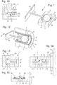
figure 11 représente, de façon schématisée et en perspective coupée, une autre variante, où la structure est aussi une carrure de la boîte de montre, sur laquelle est rapporté, du côté inaccessible à l'utilisateur, un premier insert enfermant un témoin de choc selon l'invention, et où une semelle d'un deuxième insert, dont la partie extérieure n'est pas représentée, cette semelle portant un peigne comportant plusieurs masselottes chacune à l'extrémité d'un élément de liaison ; - la
figure 12 représente, de façon schématisée et en perspective coupée, une autre variante, avec un logement cylindrique comportant plusieurs éléments sécables similaires à celui de lafigure 6 agencés sur ses génératrices, et entre lesquels est mobile une masselotte similaire ; - la
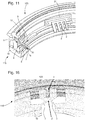
figure 13 représente, de façon similaire à lafigure 10 , une autre variante similaire, où le logement est sphérique; - la
figure 14 représente, de façon similaire à lafigure 13 , une autre variante similaire, où la masselotte est suspendue à plusieurs éléments de liaison, et où l'ensemble de l'indicateur de choc est dans un insert rapporté sur la structure, de façon similaire à lafigure 11 ; - la
figure 15 représente, de façon similaire à lafigure 14 , une autre variante similaire, où la masselotte est suspendue à deux fils, et où l'ensemble de l'indicateur de choc est dans un insert rapporté sur la structure ; - la
figure 16 représente, de façon similaire à lafigure 11 , une autre variante à l'inverse des autres variantes illustrées, où une platine de la montre comporte deux lames flexibles formant un vé et qui portent ensemble une masselotte en U, qui entoure un pion fixé dans la carrure et qui porte la surface antagoniste.
- the
figure 1 shows, schematically and in perspective, a shock indicator device according to the invention, intended to be incorporated into a watch, and comprising an impact indicator composed of a movable counterweight in a housing facing an interior surface of this housing , and in the immediate vicinity thereof, this counterweight being suspended from an elastic connecting element embedded in a structure, and arranged to generate a permanent marking, either on the internal surface of the housing, or on the proper periphery of this counterweight, in the event of a significant shock to this watch, when the acceleration imparted to this flyweight is greater than a given lower acceleration threshold; - the
figure 2 represents, similarly to thefigure 1 , another variant of impact indicator device, where only part of the housing is represented, in the form of a dihedral, and where the counterweight is less ductile than the walls of the housing, which are irreversibly deformed during a impact; - the
figure 3 represents, similarly to thefigure 2 , another variant where the walls of the housing are internally covered with a surface layer, arranged to be transferred to the counterweight in the form of a transfer deposit, under a percussion of the counterweight; - the
figure 4 represents, similarly to thefigure 2 , another variant of impact indicator device, comprising a row of weights each with a different acceleration threshold; - the
figure 5 represents, similarly to thefigure 3 , another variant of impact indicator device, comprising a row of weights each with a different acceleration threshold, and where the walls of the weights are covered externally with a surface layer, arranged to be transferred to the internal wall of the housing under the form of a transfer deposit, under a percussion of the flyweight; - the
figure 6 represents, similarly to thefigure 1 , another variant where the counterweight is arranged to strike a fragile material at the level of a breakable element arranged in the vicinity of the interior surface of the housing, and to break it when it strikes against a wall, when the counterweight is subjected to a acceleration greater than the lower acceleration threshold; - the
figure 7 shows, schematically and in perspective, another variant with a plurality of breakable elements, arranged to rupture under the effect of different acceleration thresholds, or arranged to cooperate with at least one counterweight according to the variant of thefigure 6 ; - the
Figures 8 and 9 represent, similarly to thefigure 2 , respectively before and after impact, another variant where the counterweight is more ductile than the walls of the housing, and which is irreversibly deformed during an impact; - the
figure 10 shows, schematically and in section, another variant, where the structure here is a middle part of the watch case with, in its thickness, a cylindrical housing in which a counterweight is suspended from a helical spring embedded in a screw cap in the middle, on the side inaccessible to the user; - the
figure 11 shows, schematically and in cut perspective, another variant, where the structure is also a middle part of the watch case, on which is attached, on the side inaccessible to the user, a first insert enclosing a shock indicator according to the invention, and where a sole of a second insert, the outer part of which is not shown, this sole carrying a comb comprising several weights each at the end of a connecting element; - the
figure 12 shows, schematically and in cut perspective, another variant, with a cylindrical housing comprising several breakable elements similar to that of thefigure 6 arranged on its generators, and between which a similar flyweight is movable; - the
figure 13 represents, similarly to thefigure 10 , another similar variant, where the housing is spherical; - the
figure 14 represents, similarly to thefigure 13 , another similar variant, where the counterweight is suspended from several connecting elements, and where the entire impact indicator is in an insert attached to the structure, similarly to thefigure 11 ; - the
figure 15 represents, similarly to thefigure 14 , another similar variant, where the counterweight is suspended from two wires, and where the whole of the impact indicator is in an insert attached to the structure; - the
figure 16 represents, similarly to thefigure 11 , another variant unlike the other illustrated variants, where a watch plate comprises two flexible blades forming a vee and which together carry a U-shaped weight, which surrounds a pin fixed in the middle and which carries the antagonistic surface.
L'invention concerne ainsi un dispositif indicateur de choc 1 pour montre 100, agencé pour être inséré à l'intérieur d'une montre.The invention thus relates to a
L'invention peut se présenter sous plusieurs variantes.The invention can be presented in several variants.
Le mécanisme de base comporte au moins une masselotte 2 fixée à au moins un élément de liaison 3. Dans un mode de réalisation particulier, cet élément de liaison 3 est flexible, notamment de type ressort. La masselotte 2 à l'extrémité de l'élément de liaison 3, et les rigidités axiales et/ou radiales de l'élément de liaison 3 sont connus. Il est donc facile de calculer, de manière analytique et/ou numérique et/ou expérimentale, la déflexion de l'ensemble en fonction d'une accélération appliquée.The basic mechanism comprises at least one
Plusieurs solutions sont possibles pour tirer avantage de ce comportement et sont illustrées par les figures.Several solutions are possible to take advantage of this behavior and are illustrated by the figures.
Le dispositif indicateur de choc 1 comporte une structure 10, à laquelle est fixée au moins une masselotte 2, par l'intermédiaire d'au moins un élément de liaison 3 en matériau élastique ou ductile ou fragile, déformable élastiquement ou plastiquement lors des mouvements imprimés à la masselotte 2 correspondante.The
De façon particulière et non limitative, cet élément de liaison 3 est encastré, soit directement dans la structure 10, soit dans une semelle 31 rapportée et fixée sur cette structure, ou similaire.In a particular and non-limiting manner, this connecting
Selon l'invention, au moins une masselotte 2 est mobile au voisinage d'une surface antagoniste 5 fixe, que comporte la structure 10 elle-même, ou que comporte un autre élément 120 d'une boîte 110 de montre.According to the invention, at least one
Cette masselotte 2 est agencée pour venir en contact avec cette surface antagoniste 5, de façon à imprimer, quand l'accélération imprimée à cette au moins une masselotte 2 est supérieure à un seuil inférieur d'accélération donné, un témoin d'impact ou une déformation permanente ou une rupture à la masselotte 2 et/ou à l'élément de liaison 3 et/ou à la surface antagoniste 5, ou encore à un élément sécable 8 intégré au dispositif indicateur de choc 1 quand celui-ci en comporte comme décrit plus bas dans une variante particulière visible sur la
Les valeurs d'accélération relatives à des chocs accidentels sont en général de l'ordre de 1500g à 5000g. La valeur de 1300g peut notamment être retenue comme seuil inférieur d'accélération donné.The acceleration values relating to accidental impact are generally in the range of 1500g to 5000g. The value of 1300g can notably be used as the given lower acceleration threshold.
Plus particulièrement, au moins une masselotte 2 est appairée avec une surface antagoniste 5, notamment une surface intérieure, avec laquelle la masselotte 2 est la seule à coopérer, pour former ensemble un témoin de choc 20. Plus particulièrement encore, chaque masselotte 2 est appairée avec une telle surface antagoniste 5, avec laquelle la masselotte 2 est la seule à coopérer, pour former ensemble un tel témoin de choc 20.More particularly, at least one
Dans des variantes, la masselotte 2 et/ou le composant porteur de la surface antagoniste 5 est en matériau élastique ou ductile ou fragile, déformable élastiquement ou plastiquement lors des mouvements imprimés à cette au moins une masselotte 2.In variants, the
Dans une réalisation particulière, au moins une telle masselotte 2 est mobile dans un logement 4 de la structure 10, au voisinage d'une surface antagoniste 5, notamment une surface intérieure d'une paroi 6 du logement 4. Cette masselotte 2 y est agencée pour venir en contact avec la surface antagoniste 5, notamment une surface intérieure, quand l'accélération imprimée à cette au moins une masselotte 2 est supérieure à un seuil inférieur d'accélération donné.In a particular embodiment, at least one
L'invention peut être réalisée sous des formes différentes, dont certaines sont, non limitativement, illustrées par les figures.The invention can be implemented in different forms, some of which are, without limitation, illustrated by the figures.
Tout d'abord, on voit que l'élément de liaison 3 peut être, selon la variante, en matériau élastique ou ductile ou fragile, et peut être déformable élastiquement ou plastiquement.First of all, it can be seen that the connecting
Dans la variante préférée où l'élément de liaison 3 est en matériau élastique, cet élément de liaison 3 peut notamment prendre la forme d'une lame élastique sensiblement droite, ou d'une pluralité de telles lames élastiques, notamment et non limitativement parallèles entre elles, ou encore comporter au moins un ressort hélicoïdal 32, ou un ressort spiral, ou similaire.In the preferred variant where the connecting
La lame élastique s'entend ici au sens large, ce peut être une poutre prismatique, cylindrique, ou autre, pleine ou creuse, ou un assemblage complexe de poutres élémentaires.The elastic blade is understood here in the broad sense, it can be a prismatic, cylindrical, or other beam, solid or hollow, or a complex assembly of elementary beams.
Dans une variante l'élément de liaison 3 peut encore comporter au moins un fil, notamment un fil de torsion. Dans une variante particulière, la masselotte 2 est simplement disposée entre deux fils tendus.In a variant, the connecting
Un tel élément de liaison 3, de préférence à limite d'élasticité élevée, qui est déformable élastiquement dans l'ensemble du domaine des accélérations pour lequel est conçu la montre, est conçu pour revenir à sa position de repos, ce qui permet d'enregistrer plusieurs chocs avec la même masselotte 20, et l'invention s'attache alors à déterminer l'ordre de grandeur de l'accélération maximale à laquelle la masselotte 2 a été soumise, et aussi selon quelle direction par rapport à la boîte 110 que comporte la montre 100. L'élément de liaison 3 peut notamment être réalisé dans un matériau micro-usinable, tel que silicium, diamant DLC (diamond like carbon) ou similaire, par un procédé « MEMS » ou « LIGA » ou similaire, ou encore être réalisé dans un acier à ressort d'horlogerie de module d'élasticité supérieur à 200 GPa, ou un matériau similaire.Such a connecting
Quand l'élément de liaison 3, ou la masselotte 2, ou le composant porteur de la surface antagoniste 5, est dans un matériau avec une limite d'élasticité plus basse, le domaine élastique est très étroit, et l'élément de liaison 3, ou la masselotte 2, ou le composant porteur de la surface antagoniste 5, adopte une déformation plastique permanente sous l'effet d'une accélération ou d'un choc relativement faible, facile à constater en après-vente. L'élément de liaison 3, ou la masselotte 2, ou le composant porteur de la surface antagoniste 5, peut alors être réalisé dans un alliage léger par exemple à base d'aluminium, ou un alliage précieux, à base d'argent ou d'or, ou dans un autre matériau de module d'élasticité inférieur à 70 GPa.When the connecting
Dans la variante particulière où le dispositif indicateur de choc 1 comporte un élément en matériau fragile, par exemple l'élément de liaison 3, ou un élément sécable 8, cet élément en matériau fragile est conçu pour rompre à un seuil relativement bas de limite d'élasticité; cette variante impose néanmoins que, selon le cas, l'élément de liaison 3, chaque élément sécable 8, et la masselotte 2 que porte l'élément de liaison 3, soient confinés dans un logement 4, ou bien directement si ce logement 4 est fermé et si des débris ne risquent pas de polluer le mécanisme de la montre 100, ou bien enfermés dans une enveloppe souple 9 disposée à l'intérieur du logement 4, de façon à ce que, en cas de rupture d'un élément de liaison 3, ou d'un élément sécable 8, les débris issus de cette rupture restent enfermés dans cette enveloppe souple 9. Un tel élément de liaison 3 ou un tel élément sécable 8 peut être réalisé dans un matériau de module d'élasticité inférieur à 50 GPa.In the particular variant where the
Les
La
Dans une application particulière de cette dernière variante, quand la masselotte 2 est suspendue à plusieurs éléments de liaison 3, ces derniers ne sont pas identiques, et présentent des caractéristiques différentes, par exemple un premier élément de liaison est agencé pour adopter une déformation permanente dans le domaine plastique, ou pour rompre, dès l'atteinte d'un premier seuil d'accélération, un deuxième élément de liaison est agencé pour adopter une déformation permanente dans le domaine plastique, ou pour rompre, dès l'atteinte d'un deuxième seuil d'accélération, et ainsi de suite.In a particular application of this latter variant, when the
Dans une variante, au moins un élément de liaison 3 est réalisé monobloc avec la masselotte 2 qu'il porte.In a variant, at least one connecting
Dans une autre variante, au moins un élément de liaison 3 est réalisé monobloc avec la structure 10 qui le porte.In another variant, at least one connecting
Dans une autre variante encore, au moins un élément de liaison 3 est réalisé monobloc à la fois avec la masselotte 2 qu'il porte, et avec la structure 10 qui le porte.In yet another variant, at least one connecting
Le couple entre une masselotte 2 et une surface antagoniste 5, notamment une surface intérieure formant un témoin de choc 20 est agencé de façon à permettre une visualisation facile des traces d'un choc important, par un technicien de laboratoire ou d'après-vente. A cet effet, ce témoin 20 est agencé pour laisser une trace en relief et/ou une trace visuelle, sur la masselotte 2 et/ou la surface antagoniste 5, notamment une surface intérieure.The torque between a
Dans la réalisation de la
Plus particulièrement, et tel que visible sur les variantes non limitatives illustrées, au moins une masselotte 2 est cylindrique ou sphérique, pour matérialiser la présence d'un choc selon plusieurs degrés de liberté.More particularly, and as visible on the nonlimiting variants illustrated, at least one
Dans la réalisation de la
Dans la réalisation des
Dans la réalisation de la
La
Une autre variante concerne une surface antagoniste 5 qui est une paroi de la structure 10 ou de l'autre élément 120 de la boîte de montre 110, et laquelle paroi est déformable de manière réversible. Notamment on peut utiliser une paroi 6 en matière déformable de manière réversible, par exemple une mousse, le diamètre de la zone colorée donne l'indication de l'accélération maximale subie avec une déformation réversible de la paroi 6 impactée.Another variant relates to an
Les
Tel que visible sur la variante de la
Ainsi la masselotte 2 peut venir impacter un matériau fragile tel que céramique, nickel-phosphore, saphir, ou similaire, du composant sécable 8. Si ce dernier est cassé, on peut en conclure que la masselotte 2 est venue l'impacter et on peut connaître l'accélération subie.Thus the
Comme exposé ci-dessus, dans une autre variante, il est envisageable de supprimer la masselotte 2, et d'utiliser directement la fragilité en flexion du composant sécable 8 pour calculer l'accélération subie. Le composant sécable 8 qui casse en flexion peut également être indenté pour créer des amorces de rupture. Si on utilise plusieurs composants sécables 8 en parallèle, à la façon d'un clavier tel que visible sur la
De façon particulière, au moins un logement 4 renferme complètement une masselotte 2 et le au moins un élément de liaison 3 qui est associé à cette masselotte 2. Cette configuration offre l'avantage de prévenir toute pollution de l'intérieur de la montre 100, et aussi de facilité l'inviolabilité du témoin 20 concerné. Ce logement 4 peut, notamment, appartenir à un insert 30 indexé en position par rapport à la structure 10 et fixé à cette dernière, à l'intérieur de la montre 100 et hors de portée de l'utilisateur. L'expertise peut alors être exécutée sur ce seul insert 30 une fois démonté de la montre 100 après son ouverture, cet insert 30 comportant alors un repérage complet identifiant sa position dans la montre, et sa position angulaire par rapport à la boîte 110 de la montre 100.In particular, at least one
De façon avantageuse, pour garantir l'inviolabilité, au moins un logement 4 est obturé par un bouchon 41 inaccessible à l'utilisateur de la montre 100, tel que visible sur la
De façon particulière, tel que visible sur les
La
L'invention concerne encore une montre 100 comportant au moins un tel dispositif indicateur de choc 1.The invention also relates to a
Plus particulièrement, au moins une structure 10 est fixée à un élément 120 de la boîte 110 que comporte la montre 100, ou est solidaire avec cette boîte 110, ou est une partie de cette boîte 110, notamment une carrure, ou un fond, ou un réhaut, ou une platine, ou autre.More particularly, at least one
L'invention procure de nombreux avantages :
- facilité de détermination de l'accélération maximale subie par la montre lors des essais expérimentaux ou du porté client ;
- possibilité de moduler la précision souhaitée sur la valeur de l'accélération maximale ;
- facilité de réalisation de la mesure pratique de l'accélération maximale, par comparaison de la zone d'impact avec des mesures de référence ;
- possibilité de mesure selon plusieurs axes, voire selon les trois dimensions ;
- possibilité d'encastrement du dispositif indicateur de choc dans un composant de structure de la montre, tel que carrure, platine, fond, ou autre, sans nécessiter d'organe saillant à position variable ;
- utilisation d'espaces libres quelconques de la montre pour le positionnement du dispositif indicateur de choc ;
- facilité de remplacement du dispositif, avec un seul composant à changer après expertise;
- faible encombrement du dispositif ;
- faible coût.
- ease of determining the maximum acceleration undergone by the watch during experimental tests or customer support;
- possibility of modulating the desired precision on the value of maximum acceleration;
- ease of carrying out the practical measurement of maximum acceleration, by comparison of the impact area with reference measurements;
- possibility of measurement according to several axes, even according to the three dimensions;
- possibility of embedding the impact indicator device in a structural component of the watch, such as middle part, plate, back, or the like, without requiring a protruding member with variable position;
- use of any free spaces of the watch for positioning the shock indicator device;
- easy replacement of the device, with a single component to be changed after appraisal;
- small size of the device;
- low cost.
Claims (23)
- Shock indicator device (1) for a watch (100), arranged to be inserted inside a watch, and comprising a structure (10) to which is fixed at least one inertia block (2) by means of at least one connecting element (3) made of elastic or ductile or breakable material, which is elastically or plastically deformable when movements are imparted to said at least one inertia block (2), characterized in that at least one said inertia block (2) is movable in proximity to a fixed opposing surface (5) comprised in said structure (10) itself or another element (120) of a watch case (110), and is arranged to come into contact with said opposing surface (5), so as to impart a proof indicator of impact or a permanent deformation or damage to said inertia block (2) and/or to said connecting element (3) and/or to said opposing surface (5), or to a breakable element (8) incorporated in said shock indicator device (1), when the acceleration imparted to said at least one inertia block (2) is higher than a given lower acceleration threshold.
- Shock indicator device (1) according to claim 1, characterized in that at least one said inertia block (2) is paired with a said opposing surface (5) with which only said inertia block (2) cooperates, to form together a shock proof indicator (20).
- Shock indicator device (1) according to claim 1 or 2, characterized in that at least one said inertia block (2) is movable inside a housing (4) of said structure (10) in proximity to said opposing surface (5) which is an inner surface of a wall (6) of said housing (4), and is arranged to come into contact with said opposing surface (5), when the acceleration imparted to said at least one inertia block (2) is higher than a given lower acceleration threshold.
- Shock indicator device (1) according to one of claims 1 to 3, characterized in that said inertia block (2) and/or the component bearing said opposing surface (5) is made of elastic or ductile or breakable material, which is elastically or plastically deformable when movements are imparted to said at least one inertia block (2).
- Shock indicator device (1) according to claims 2 and 3, or according to one of the claims dependent on claims 2 and 3, characterized in that, in a said shock proof indicator (20), said wall (6) is arranged to undergo a local irreversible deformation when struck by said inertia block (2) when said inertia block (2) is subjected to a higher acceleration than said lower acceleration threshold.
- Shock indicator device (1) according to claims 2 and 3, or according to one of the claims dependent on claims 2 and 3, characterized in that, in a said shock proof indicator (20), said inertia block (2) is arranged to undergo a local irreversible deformation on striking against a said wall (6), when said inertia block is subjected to a higher acceleration than said lower acceleration threshold.
- Shock indicator device (1) according to claims 2 and 3, or according to one of the claims dependent on claims 2 and 3, characterized in that, in a said shock proof indicator (20), said wall (6) is coated, on said opposing surface (5), with a surface layer (7) arranged to be at least partially transferred onto said inertia block (2) when struck by said inertia block (2), when said inertia block (2) is subjected to an acceleration higher than said lower acceleration threshold.
- Shock indicator device (1) according to claims 2 and 3, or according to one of the claims dependent on claims 2 and 3, characterized in that, in a said shock proof indicator (20), said inertia block (2) is coated with a surface layer (7) arranged to be at least partially transferred onto said opposing surface (5), when said inertia block strikes against a said wall (6), when said inertia block is subjected to an acceleration higher than said lower acceleration threshold.
- Shock indicator device (1) according to one of claims 1 to 8, characterized in that said opposing surface (5) is a wall of said structure (10) or of said other element (120), and said wall is reversibly deformable.
- Shock indicator device (1) according to claims 2 and 3, or according to one of the claims dependent on claims 2 and 3, characterized in that, in a said shock proof indicator (20), said inertia block (2) is arranged to strike a breakable element (8) arranged in proximity to said opposing surface (5), and to at least partially break said breakable element (8) when the latter collides with said inertia block (2) and/or with a said wall (6), when said inertia block is subjected to a higher acceleration than said lower acceleration threshold.
- Shock indicator device (1) according to claim 10, characterized in that at least one said breakable element (8) is enclosed in a flexible envelope (9) inside said housing (4) so that, in the event of damage to said breakable element (8), the debris from said damage remains enclosed in said flexible envelope (9).
- Shock indicator device (1) according to claim 3 or according to one of the claims dependent on claim 3, characterized in that at least one said housing (4) completely encloses a said inertia block (2) and said at least one connecting element (3) associated with said inertia block (2).
- Shock indicator device (1) according to one of claims 1 to 12, characterized in that at least one said opposing surface (5) arranged to cooperate with a said inertia block (2) is cylindrical or spherical to mark the presence of a shock in several degrees of freedom.
- Shock indicator device (1) according to one of claims 1 to 13, characterized in that at least one said inertia block (2) is cylindrical or spherical to mark the presence of a shock in several degrees of freedom.
- Shock indicator device (1) according to one of claims 1 to 14, characterized in that at least one said connecting element (3) is a substantially straight, solid or tubular elastic strip.
- Shock indicator device (1) according to one of claims 1 to 14, characterized in that at least one said connecting element (3) includes at least one wire.
- Shock indicator device (1) according to one of claims 1 to 14, characterized in that at least one said connecting element (3) includes at least one helical spring (32) or one spiral spring.
- Shock indicator device (1) according to one of claims 1 to 17, characterized in that said device (1) includes a plurality of said connecting elements (3).
- Shock indicator device (1) according to claim 18, characterized in that said connecting elements (3) are not identical, and have different features, and are each arranged to experience a permanent deformation in the plastic range, or to break, as soon as an acceleration threshold, distinct from that of the other said connecting elements (3), is reached.
- Shock indicator device (1) according to one of claims 1 to 19, characterized in that at least one said housing (4) is sealed by a cap (41) inaccessible to the user of said watch (100).
- Shock indicator device (1) according to claim 2 or one of the claims dependent on claim 2, characterized in that said device (1) includes a plurality of said shock proof indicators (20) which are distinguished by distinct lower acceleration thresholds.
- Watch (100) including at least one shock indicator device (1) according to one of claims 1 to 21.
- Watch (100) according to claim 22, characterized in that at least one said structure (10) is fixed to an element of the case (110) of said watch (100) or is integral with said case (110) or is a part of said case (110).
Priority Applications (4)
| Application Number | Priority Date | Filing Date | Title |
|---|---|---|---|
| EP17180057.6A EP3425457B1 (en) | 2017-07-06 | 2017-07-06 | Watch shock indicator |
| US16/021,070 US11281162B2 (en) | 2017-07-06 | 2018-06-28 | Shock indicator for watches |
| JP2018126653A JP6557386B2 (en) | 2017-07-06 | 2018-07-03 | Impact indicator device for wristwatch |
| CN201810731732.6A CN109239397B (en) | 2017-07-06 | 2018-07-05 | Impact indicator for a watch |
Applications Claiming Priority (1)
| Application Number | Priority Date | Filing Date | Title |
|---|---|---|---|
| EP17180057.6A EP3425457B1 (en) | 2017-07-06 | 2017-07-06 | Watch shock indicator |
Publications (2)
| Publication Number | Publication Date |
|---|---|
| EP3425457A1 EP3425457A1 (en) | 2019-01-09 |
| EP3425457B1 true EP3425457B1 (en) | 2020-05-27 |
Family
ID=59295092
Family Applications (1)
| Application Number | Title | Priority Date | Filing Date |
|---|---|---|---|
| EP17180057.6A Active EP3425457B1 (en) | 2017-07-06 | 2017-07-06 | Watch shock indicator |
Country Status (4)
| Country | Link |
|---|---|
| US (1) | US11281162B2 (en) |
| EP (1) | EP3425457B1 (en) |
| JP (1) | JP6557386B2 (en) |
| CN (1) | CN109239397B (en) |
Families Citing this family (2)
| Publication number | Priority date | Publication date | Assignee | Title |
|---|---|---|---|---|
| CN109606915A (en) * | 2019-02-14 | 2019-04-12 | 珠海格力电器股份有限公司 | Product state detection device and packing box |
| EP3971655A1 (en) * | 2020-09-18 | 2022-03-23 | ETA SA Manufacture Horlogère Suisse | Shock-proof protection with abutment for a resonator mechanism with rotatable flexible guiding |
Family Cites Families (23)
| Publication number | Priority date | Publication date | Assignee | Title |
|---|---|---|---|---|
| FR2283445A1 (en) * | 1974-08-30 | 1976-03-26 | Avice Pierre | Shock detector using moving weight - has weight biased to neutral position and engaging indicators held by friction |
| JP2887556B2 (en) * | 1993-10-01 | 1999-04-26 | 株式会社生方製作所 | Acceleration response switch |
| JP2001099857A (en) * | 1999-09-30 | 2001-04-13 | Akebono Brake Ind Co Ltd | Shock detection indicator component and method of investigating shock history |
| JP2001099854A (en) | 1999-10-01 | 2001-04-13 | Akebono Brake Ind Co Ltd | Three-dimensional shock detecting and display member |
| US6357382B1 (en) * | 2000-04-04 | 2002-03-19 | Lloyd Douglas Clark | Audible warning device with restrainable, tilt-activated mechanism |
| KR20050009750A (en) * | 2002-06-14 | 2005-01-25 | 쓰리엠 이노베이티브 프로퍼티즈 컴파니 | Shock indicator |
| US6698272B1 (en) * | 2002-12-30 | 2004-03-02 | International Business Machines Corporation | Device for indicating exposure to an impact, adverse temperature and/or humidity |
| US7409851B2 (en) * | 2005-03-29 | 2008-08-12 | Cornell Research Foundation, Inc. | Detection of small bound mass |
| KR100823864B1 (en) * | 2006-11-16 | 2008-04-21 | 이성남 | Shock indicator |
| TWI365978B (en) * | 2007-12-28 | 2012-06-11 | Ind Tech Res Inst | Method and apparatus for dropping indicator |
| CN101514996B (en) * | 2008-02-20 | 2011-04-13 | 财团法人工业技术研究院 | Stress indicator |
| JP5424082B2 (en) * | 2008-04-02 | 2014-02-26 | 株式会社リコー | Impact detection device, packing device |
| CN101419868B (en) * | 2008-11-06 | 2010-07-14 | 北京大学 | Micro mechanical latching switch device |
| CH701867B1 (en) * | 2009-09-30 | 2014-02-28 | Mhvj Manufacture Horlogere Vallee De Joux | Wristwatch including a mechanical accelerometer. |
| CN101750519B (en) * | 2009-12-11 | 2013-06-26 | 中国科学院上海微系统与信息技术研究所 | Self-tracking identification method and system of lateral response wave of high-range acceleration transducer |
| CN101752141A (en) * | 2009-12-21 | 2010-06-23 | 西安电子科技大学 | A kind of flexion type acceleration switch |
| EP2684059B1 (en) | 2011-03-10 | 2015-08-26 | Shockwatch, Inc. | Impact indicator |
| KR101838633B1 (en) * | 2011-07-22 | 2018-03-14 | 엘지전자 주식회사 | Mobile terminal and vibration power control method thereof |
| ITTO20120691A1 (en) * | 2012-08-01 | 2014-02-02 | Milano Politecnico | IMPACT SENSOR WITH BISTABLE MECHANISM AND METHOD FOR DETECTING IMPACTS |
| US9291511B2 (en) | 2013-09-23 | 2016-03-22 | Xerox Corporation | Shock or impact sensor |
| US20150265214A1 (en) * | 2014-03-24 | 2015-09-24 | Samsung Electronics Co., Ltd. | Adjustable sensor support structure for optimizing skin contact |
| CN204667442U (en) * | 2015-05-20 | 2015-09-23 | 万又企业有限公司 | The surge indicator of multiple judgement structure |
| CN105093913B (en) * | 2015-09-21 | 2018-07-03 | 京东方科技集团股份有限公司 | Smartwatch, method of controlling operation thereof and device |
-
2017
- 2017-07-06 EP EP17180057.6A patent/EP3425457B1/en active Active
-
2018
- 2018-06-28 US US16/021,070 patent/US11281162B2/en active Active
- 2018-07-03 JP JP2018126653A patent/JP6557386B2/en active Active
- 2018-07-05 CN CN201810731732.6A patent/CN109239397B/en active Active
Non-Patent Citations (1)
| Title |
|---|
| None * |
Also Published As
| Publication number | Publication date |
|---|---|
| EP3425457A1 (en) | 2019-01-09 |
| US11281162B2 (en) | 2022-03-22 |
| JP6557386B2 (en) | 2019-08-07 |
| CN109239397B (en) | 2020-11-10 |
| CN109239397A (en) | 2019-01-18 |
| US20190011888A1 (en) | 2019-01-10 |
| JP2019015726A (en) | 2019-01-31 |
Similar Documents
| Publication | Publication Date | Title |
|---|---|---|
| EP3425457B1 (en) | Watch shock indicator | |
| EP2938569B1 (en) | Micro-electromechanical device comprising a mobile mass that can move out-of-plane | |
| EP2944725A1 (en) | Dynamic penetrometer, measurement unit, system and method for determining the compactness and bearing capacity of a floor | |
| WO2016096677A1 (en) | Timepiece resonator with crossed blades | |
| EP2405238B1 (en) | Vibrating disk inertial rotary motion sensor | |
| CH713165B1 (en) | Protection of the blades of a mechanical watch resonator in the event of an impact. | |
| EP2824520A1 (en) | Acoustic identification of a mechanical watch movement | |
| FR2941525A1 (en) | GYROMETER IN SURFACE TECHNOLOGY, DETECTION OFFLINE BY MEASURING GAUGE. | |
| EP3382470B1 (en) | Timepiece oscillator with a flexible pivot | |
| EP1416174A1 (en) | Fixing element with controlling means for integrity | |
| CH713137A2 (en) | Protection of a resonator mechanism with blades against axial shocks. | |
| EP2690507A1 (en) | Holorological hairspring | |
| CH713956A2 (en) | Shock indicator for watch. | |
| EP3719587B1 (en) | Shock-absorber device and timepiece mechanical oscillator with flexible guide having such a shock-absorber device | |
| EP1666832A1 (en) | Motorised orientable measuring head | |
| CH708038A1 (en) | watch movement in three-dimensional resonant controller. | |
| FR2893139A1 (en) | Silicon microsensor for e.g. weapon, has inertial mass and toothed wheel disposed in concentric manner such that tooth engages with toothed wheel, and elastic anchoring device limiting rotation of toothed wheel during detection of shock | |
| EP3812848A1 (en) | Measuring device for a mechanical watch | |
| CH708301A2 (en) | Device for checking the authenticity of a mechanical movement of a watch. | |
| CH714218A2 (en) | Device for detecting and memorizing a shock for a portable object, more particularly a timepiece. | |
| CH716321A2 (en) | Oscillator for watch movement. | |
| WO2017137926A1 (en) | Clock device for measuring the time spent in weightlessness | |
| CH712864B1 (en) | Diaphragm shock absorber for timepiece. | |
| CH712890B1 (en) | Oscillating weight mechanism for measuring physical activity. | |
| CH108299A (en) | A method and apparatus for testing the hardness of metals and other materials. |
Legal Events
| Date | Code | Title | Description |
|---|---|---|---|
| PUAI | Public reference made under article 153(3) epc to a published international application that has entered the european phase |
Free format text: ORIGINAL CODE: 0009012 |
|
| STAA | Information on the status of an ep patent application or granted ep patent |
Free format text: STATUS: THE APPLICATION HAS BEEN PUBLISHED |
|
| AK | Designated contracting states |
Kind code of ref document: A1 Designated state(s): AL AT BE BG CH CY CZ DE DK EE ES FI FR GB GR HR HU IE IS IT LI LT LU LV MC MK MT NL NO PL PT RO RS SE SI SK SM TR |
|
| AX | Request for extension of the european patent |
Extension state: BA ME |
|
| STAA | Information on the status of an ep patent application or granted ep patent |
Free format text: STATUS: REQUEST FOR EXAMINATION WAS MADE |
|
| 17P | Request for examination filed |
Effective date: 20190709 |
|
| RBV | Designated contracting states (corrected) |
Designated state(s): AL AT BE BG CH CY CZ DE DK EE ES FI FR GB GR HR HU IE IS IT LI LT LU LV MC MK MT NL NO PL PT RO RS SE SI SK SM TR |
|
| RIC1 | Information provided on ipc code assigned before grant |
Ipc: G04B 47/06 20060101ALI20191128BHEP Ipc: G01P 15/08 20060101ALI20191128BHEP Ipc: G04B 43/00 20060101AFI20191128BHEP Ipc: G01P 15/03 20060101ALI20191128BHEP |
|
| GRAP | Despatch of communication of intention to grant a patent |
Free format text: ORIGINAL CODE: EPIDOSNIGR1 |
|
| STAA | Information on the status of an ep patent application or granted ep patent |
Free format text: STATUS: GRANT OF PATENT IS INTENDED |
|
| INTG | Intention to grant announced |
Effective date: 20200113 |
|
| RIN1 | Information on inventor provided before grant (corrected) |
Inventor name: LENOIR, DEIRDRE |
|
| GRAS | Grant fee paid |
Free format text: ORIGINAL CODE: EPIDOSNIGR3 |
|
| GRAA | (expected) grant |
Free format text: ORIGINAL CODE: 0009210 |
|
| STAA | Information on the status of an ep patent application or granted ep patent |
Free format text: STATUS: THE PATENT HAS BEEN GRANTED |
|
| AK | Designated contracting states |
Kind code of ref document: B1 Designated state(s): AL AT BE BG CH CY CZ DE DK EE ES FI FR GB GR HR HU IE IS IT LI LT LU LV MC MK MT NL NO PL PT RO RS SE SI SK SM TR |
|
| REG | Reference to a national code |
Ref country code: GB Ref legal event code: FG4D Free format text: NOT ENGLISH |
|
| REG | Reference to a national code |
Ref country code: CH Ref legal event code: EP |
|
| REG | Reference to a national code |
Ref country code: CH Ref legal event code: NV Representative=s name: ICB INGENIEURS CONSEILS EN BREVETS SA, CH Ref country code: AT Ref legal event code: REF Ref document number: 1275189 Country of ref document: AT Kind code of ref document: T Effective date: 20200615 |
|
| REG | Reference to a national code |
Ref country code: DE Ref legal event code: R096 Ref document number: 602017017189 Country of ref document: DE |
|
| REG | Reference to a national code |
Ref country code: LT Ref legal event code: MG4D |
|
| PG25 | Lapsed in a contracting state [announced via postgrant information from national office to epo] |
Ref country code: FI Free format text: LAPSE BECAUSE OF FAILURE TO SUBMIT A TRANSLATION OF THE DESCRIPTION OR TO PAY THE FEE WITHIN THE PRESCRIBED TIME-LIMIT Effective date: 20200527 Ref country code: LT Free format text: LAPSE BECAUSE OF FAILURE TO SUBMIT A TRANSLATION OF THE DESCRIPTION OR TO PAY THE FEE WITHIN THE PRESCRIBED TIME-LIMIT Effective date: 20200527 Ref country code: IS Free format text: LAPSE BECAUSE OF FAILURE TO SUBMIT A TRANSLATION OF THE DESCRIPTION OR TO PAY THE FEE WITHIN THE PRESCRIBED TIME-LIMIT Effective date: 20200927 Ref country code: SE Free format text: LAPSE BECAUSE OF FAILURE TO SUBMIT A TRANSLATION OF THE DESCRIPTION OR TO PAY THE FEE WITHIN THE PRESCRIBED TIME-LIMIT Effective date: 20200527 Ref country code: NO Free format text: LAPSE BECAUSE OF FAILURE TO SUBMIT A TRANSLATION OF THE DESCRIPTION OR TO PAY THE FEE WITHIN THE PRESCRIBED TIME-LIMIT Effective date: 20200827 Ref country code: GR Free format text: LAPSE BECAUSE OF FAILURE TO SUBMIT A TRANSLATION OF THE DESCRIPTION OR TO PAY THE FEE WITHIN THE PRESCRIBED TIME-LIMIT Effective date: 20200828 Ref country code: PT Free format text: LAPSE BECAUSE OF FAILURE TO SUBMIT A TRANSLATION OF THE DESCRIPTION OR TO PAY THE FEE WITHIN THE PRESCRIBED TIME-LIMIT Effective date: 20200928 |
|
| REG | Reference to a national code |
Ref country code: NL Ref legal event code: MP Effective date: 20200527 |
|
| PG25 | Lapsed in a contracting state [announced via postgrant information from national office to epo] |
Ref country code: HR Free format text: LAPSE BECAUSE OF FAILURE TO SUBMIT A TRANSLATION OF THE DESCRIPTION OR TO PAY THE FEE WITHIN THE PRESCRIBED TIME-LIMIT Effective date: 20200527 Ref country code: RS Free format text: LAPSE BECAUSE OF FAILURE TO SUBMIT A TRANSLATION OF THE DESCRIPTION OR TO PAY THE FEE WITHIN THE PRESCRIBED TIME-LIMIT Effective date: 20200527 Ref country code: LV Free format text: LAPSE BECAUSE OF FAILURE TO SUBMIT A TRANSLATION OF THE DESCRIPTION OR TO PAY THE FEE WITHIN THE PRESCRIBED TIME-LIMIT Effective date: 20200527 Ref country code: BG Free format text: LAPSE BECAUSE OF FAILURE TO SUBMIT A TRANSLATION OF THE DESCRIPTION OR TO PAY THE FEE WITHIN THE PRESCRIBED TIME-LIMIT Effective date: 20200827 |
|
| REG | Reference to a national code |
Ref country code: AT Ref legal event code: MK05 Ref document number: 1275189 Country of ref document: AT Kind code of ref document: T Effective date: 20200527 |
|
| PG25 | Lapsed in a contracting state [announced via postgrant information from national office to epo] |
Ref country code: AL Free format text: LAPSE BECAUSE OF FAILURE TO SUBMIT A TRANSLATION OF THE DESCRIPTION OR TO PAY THE FEE WITHIN THE PRESCRIBED TIME-LIMIT Effective date: 20200527 Ref country code: NL Free format text: LAPSE BECAUSE OF FAILURE TO SUBMIT A TRANSLATION OF THE DESCRIPTION OR TO PAY THE FEE WITHIN THE PRESCRIBED TIME-LIMIT Effective date: 20200527 |
|
| PG25 | Lapsed in a contracting state [announced via postgrant information from national office to epo] |
Ref country code: ES Free format text: LAPSE BECAUSE OF FAILURE TO SUBMIT A TRANSLATION OF THE DESCRIPTION OR TO PAY THE FEE WITHIN THE PRESCRIBED TIME-LIMIT Effective date: 20200527 Ref country code: SM Free format text: LAPSE BECAUSE OF FAILURE TO SUBMIT A TRANSLATION OF THE DESCRIPTION OR TO PAY THE FEE WITHIN THE PRESCRIBED TIME-LIMIT Effective date: 20200527 Ref country code: EE Free format text: LAPSE BECAUSE OF FAILURE TO SUBMIT A TRANSLATION OF THE DESCRIPTION OR TO PAY THE FEE WITHIN THE PRESCRIBED TIME-LIMIT Effective date: 20200527 Ref country code: DK Free format text: LAPSE BECAUSE OF FAILURE TO SUBMIT A TRANSLATION OF THE DESCRIPTION OR TO PAY THE FEE WITHIN THE PRESCRIBED TIME-LIMIT Effective date: 20200527 Ref country code: IT Free format text: LAPSE BECAUSE OF FAILURE TO SUBMIT A TRANSLATION OF THE DESCRIPTION OR TO PAY THE FEE WITHIN THE PRESCRIBED TIME-LIMIT Effective date: 20200527 Ref country code: RO Free format text: LAPSE BECAUSE OF FAILURE TO SUBMIT A TRANSLATION OF THE DESCRIPTION OR TO PAY THE FEE WITHIN THE PRESCRIBED TIME-LIMIT Effective date: 20200527 Ref country code: AT Free format text: LAPSE BECAUSE OF FAILURE TO SUBMIT A TRANSLATION OF THE DESCRIPTION OR TO PAY THE FEE WITHIN THE PRESCRIBED TIME-LIMIT Effective date: 20200527 Ref country code: CZ Free format text: LAPSE BECAUSE OF FAILURE TO SUBMIT A TRANSLATION OF THE DESCRIPTION OR TO PAY THE FEE WITHIN THE PRESCRIBED TIME-LIMIT Effective date: 20200527 |
|
| PG25 | Lapsed in a contracting state [announced via postgrant information from national office to epo] |
Ref country code: PL Free format text: LAPSE BECAUSE OF FAILURE TO SUBMIT A TRANSLATION OF THE DESCRIPTION OR TO PAY THE FEE WITHIN THE PRESCRIBED TIME-LIMIT Effective date: 20200527 Ref country code: SK Free format text: LAPSE BECAUSE OF FAILURE TO SUBMIT A TRANSLATION OF THE DESCRIPTION OR TO PAY THE FEE WITHIN THE PRESCRIBED TIME-LIMIT Effective date: 20200527 Ref country code: MC Free format text: LAPSE BECAUSE OF FAILURE TO SUBMIT A TRANSLATION OF THE DESCRIPTION OR TO PAY THE FEE WITHIN THE PRESCRIBED TIME-LIMIT Effective date: 20200527 |
|
| REG | Reference to a national code |
Ref country code: DE Ref legal event code: R097 Ref document number: 602017017189 Country of ref document: DE |
|
| PLBE | No opposition filed within time limit |
Free format text: ORIGINAL CODE: 0009261 |
|
| STAA | Information on the status of an ep patent application or granted ep patent |
Free format text: STATUS: NO OPPOSITION FILED WITHIN TIME LIMIT |
|
| REG | Reference to a national code |
Ref country code: BE Ref legal event code: MM Effective date: 20200731 |
|
| PG25 | Lapsed in a contracting state [announced via postgrant information from national office to epo] |
Ref country code: LU Free format text: LAPSE BECAUSE OF NON-PAYMENT OF DUE FEES Effective date: 20200706 Ref country code: IE Free format text: LAPSE BECAUSE OF NON-PAYMENT OF DUE FEES Effective date: 20200706 |
|
| 26N | No opposition filed |
Effective date: 20210302 |
|
| PG25 | Lapsed in a contracting state [announced via postgrant information from national office to epo] |
Ref country code: BE Free format text: LAPSE BECAUSE OF NON-PAYMENT OF DUE FEES Effective date: 20200731 Ref country code: SI Free format text: LAPSE BECAUSE OF FAILURE TO SUBMIT A TRANSLATION OF THE DESCRIPTION OR TO PAY THE FEE WITHIN THE PRESCRIBED TIME-LIMIT Effective date: 20200527 |
|
| PG25 | Lapsed in a contracting state [announced via postgrant information from national office to epo] |
Ref country code: TR Free format text: LAPSE BECAUSE OF FAILURE TO SUBMIT A TRANSLATION OF THE DESCRIPTION OR TO PAY THE FEE WITHIN THE PRESCRIBED TIME-LIMIT Effective date: 20200527 Ref country code: MT Free format text: LAPSE BECAUSE OF FAILURE TO SUBMIT A TRANSLATION OF THE DESCRIPTION OR TO PAY THE FEE WITHIN THE PRESCRIBED TIME-LIMIT Effective date: 20200527 Ref country code: CY Free format text: LAPSE BECAUSE OF FAILURE TO SUBMIT A TRANSLATION OF THE DESCRIPTION OR TO PAY THE FEE WITHIN THE PRESCRIBED TIME-LIMIT Effective date: 20200527 |
|
| PG25 | Lapsed in a contracting state [announced via postgrant information from national office to epo] |
Ref country code: MK Free format text: LAPSE BECAUSE OF FAILURE TO SUBMIT A TRANSLATION OF THE DESCRIPTION OR TO PAY THE FEE WITHIN THE PRESCRIBED TIME-LIMIT Effective date: 20200527 |
|
| P01 | Opt-out of the competence of the unified patent court (upc) registered |
Effective date: 20230611 |
|
| PGFP | Annual fee paid to national office [announced via postgrant information from national office to epo] |
Ref country code: CH Payment date: 20230801 Year of fee payment: 7 |
|
| PGFP | Annual fee paid to national office [announced via postgrant information from national office to epo] |
Ref country code: DE Payment date: 20230620 Year of fee payment: 7 |
|
| PGFP | Annual fee paid to national office [announced via postgrant information from national office to epo] |
Ref country code: GB Payment date: 20240620 Year of fee payment: 8 |
|
| PGFP | Annual fee paid to national office [announced via postgrant information from national office to epo] |
Ref country code: FR Payment date: 20240619 Year of fee payment: 8 |