JP5768611B2 - Image forming apparatus - Google Patents
Image forming apparatus Download PDFInfo
- Publication number
- JP5768611B2 JP5768611B2 JP2011195993A JP2011195993A JP5768611B2 JP 5768611 B2 JP5768611 B2 JP 5768611B2 JP 2011195993 A JP2011195993 A JP 2011195993A JP 2011195993 A JP2011195993 A JP 2011195993A JP 5768611 B2 JP5768611 B2 JP 5768611B2
- Authority
- JP
- Japan
- Prior art keywords
- light
- cartridge
- optical member
- toner
- optical
- Prior art date
- Legal status (The legal status is an assumption and is not a legal conclusion. Google has not performed a legal analysis and makes no representation as to the accuracy of the status listed.)
- Expired - Fee Related
Links
- 230000003287 optical effect Effects 0.000 claims description 275
- 238000001514 detection method Methods 0.000 claims description 66
- 230000007246 mechanism Effects 0.000 claims description 39
- 230000005540 biological transmission Effects 0.000 claims description 3
- 238000000034 method Methods 0.000 description 17
- 238000002834 transmittance Methods 0.000 description 15
- 230000008569 process Effects 0.000 description 14
- 239000003086 colorant Substances 0.000 description 9
- 230000002950 deficient Effects 0.000 description 9
- 239000003973 paint Substances 0.000 description 8
- 230000000694 effects Effects 0.000 description 6
- 230000035699 permeability Effects 0.000 description 6
- 238000004140 cleaning Methods 0.000 description 5
- 239000002699 waste material Substances 0.000 description 5
- 230000005684 electric field Effects 0.000 description 4
- 239000000463 material Substances 0.000 description 4
- JOYRKODLDBILNP-UHFFFAOYSA-N Ethyl urethane Chemical compound CCOC(N)=O JOYRKODLDBILNP-UHFFFAOYSA-N 0.000 description 3
- 230000015572 biosynthetic process Effects 0.000 description 3
- 230000007547 defect Effects 0.000 description 3
- 238000012423 maintenance Methods 0.000 description 3
- 230000002093 peripheral effect Effects 0.000 description 3
- 239000006261 foam material Substances 0.000 description 2
- 238000010438 heat treatment Methods 0.000 description 2
- 238000004519 manufacturing process Methods 0.000 description 2
- 238000000926 separation method Methods 0.000 description 2
- 238000003756 stirring Methods 0.000 description 2
- 239000004925 Acrylic resin Substances 0.000 description 1
- 229920000178 Acrylic resin Polymers 0.000 description 1
- 230000002159 abnormal effect Effects 0.000 description 1
- 230000004931 aggregating effect Effects 0.000 description 1
- 230000033228 biological regulation Effects 0.000 description 1
- 238000006243 chemical reaction Methods 0.000 description 1
- 238000010586 diagram Methods 0.000 description 1
- 238000007599 discharging Methods 0.000 description 1
- 239000006260 foam Substances 0.000 description 1
- 239000011521 glass Substances 0.000 description 1
- 230000001788 irregular Effects 0.000 description 1
- 239000004973 liquid crystal related substance Substances 0.000 description 1
- 230000013011 mating Effects 0.000 description 1
- 238000012986 modification Methods 0.000 description 1
- 230000004048 modification Effects 0.000 description 1
- 230000003472 neutralizing effect Effects 0.000 description 1
- 239000004033 plastic Substances 0.000 description 1
- 229920005668 polycarbonate resin Polymers 0.000 description 1
- 239000004431 polycarbonate resin Substances 0.000 description 1
- 229920005990 polystyrene resin Polymers 0.000 description 1
- 230000009467 reduction Effects 0.000 description 1
- 230000001105 regulatory effect Effects 0.000 description 1
- 238000007789 sealing Methods 0.000 description 1
- 239000004065 semiconductor Substances 0.000 description 1
- 229910001220 stainless steel Inorganic materials 0.000 description 1
- 239000010935 stainless steel Substances 0.000 description 1
- 230000003068 static effect Effects 0.000 description 1
Images


Description
本発明は、画像形成装置に関する。 The present invention relates to an image forming apparatus.
複写機、ファクシミリ、レーザビームプリンタなどに用いられる電子写真装置では、現像剤として、トナーおよびキャリアとからなる二成分系と、トナーのみからなる一成分系のいずれかが使用される。二成分系の現像剤では、キャリアは現像機内で再利用されるが、印刷に応じてトナーが消費されるため、適宜トナーの補給が必要となる。トナー補給を行う一つの方法として、着脱可能な回転式トナーボトルを用い、該トナーボトルに新しいトナーを充填して画像形成装置に装着する方法がある。トナーボトル装着後、トナーボトルを回転させることで現像部にトナーが補給される。 In an electrophotographic apparatus used for a copying machine, a facsimile, a laser beam printer, or the like, either a two-component system composed of toner and a carrier or a one-component system composed only of toner is used as a developer. In the two-component developer, the carrier is reused in the developing machine. However, since toner is consumed in accordance with printing, it is necessary to replenish the toner appropriately. As one method for supplying toner, there is a method in which a detachable rotary toner bottle is used, and a new toner is filled in the toner bottle and mounted on the image forming apparatus. After the toner bottle is attached, the toner is replenished by rotating the toner bottle.
一方、一成分系の現像剤の場合は、感光体ドラム、現像機、帯電手段などを有する作像ユニットに対して着脱可能なトナーカートリッジによって現像機にトナー補給を行う。また、一成分系の現像剤については、トナーカートリッジと作像ユニットとを一体化した、いわゆるオールインワン型のカートリッジもある。このタイプのカートリッジは、トナーが無くなったときや作像ユニットが寿命となったときに、カートリッジ全体を交換する。 On the other hand, in the case of a one-component developer, the developer is replenished with a toner cartridge that can be attached to and detached from an image forming unit having a photosensitive drum, a developing machine, a charging unit, and the like. As for a one-component developer, there is a so-called all-in-one type cartridge in which a toner cartridge and an image forming unit are integrated. This type of cartridge is replaced when the toner runs out or when the image forming unit has reached the end of its life.
フルカラーの画像形成装置においては、複数のトナーボトルや、トナーカートリッジ、作像ユニット(上記オールインワン型も含む)を、カートリッジとして画像形成装置本体に着脱可能に装着する場合が多い。ここで、これらカートリッジを装着していない未装着状態や、または異なる種類や異なる色のトナーのカートリッジを装着した誤装着状態で印刷を実行すると、印刷品質の低下などを生じるおそれがある。例えば誤装着により異なる種類のトナーを補給すると、トナーの帯電特性が異なる場合には、トナー同士が接触した際にトナー間の電荷が移動することで本来の帯電特性と異なる特性となるため、かぶりをはじめとする異常画像が発生するおそれがある。また、異なる色のトナーが混入すると、たとえ微量であっても混色となるため、印刷品質の低下を招く。 In a full-color image forming apparatus, a plurality of toner bottles, toner cartridges, and image forming units (including the all-in-one type) are often detachably mounted as cartridges on the image forming apparatus main body. Here, when printing is performed in a state in which these cartridges are not mounted, or in an erroneous mounting state in which a cartridge of a different type or color of toner is mounted, there is a possibility that print quality may be deteriorated. For example, when different types of toner are replenished due to incorrect mounting, if the toner charging characteristics differ, the charge between the toners moves when the toners come into contact with each other, resulting in characteristics different from the original charging characteristics. There is a risk that abnormal images such as will occur. In addition, when toners of different colors are mixed, even if the amount is very small, the colors are mixed, resulting in a decrease in print quality.
カートリッジの未装着あるいは誤装着を防止するため、特許3650678号公報(特許文献1)、特開2010−204353号公報(特許文献2)、特開平09−160469号公報(特許文献3)、あるいは特開2006−142484号公報(特許文献4)などが提案されている。 In order to prevent the cartridge from being unmounted or erroneously mounted, Japanese Patent No. 3650678 (Patent Document 1), Japanese Patent Application Laid-Open No. 2010-204353 (Patent Document 2), Japanese Patent Application Laid-Open No. 09-160469 (Patent Document 3), or Japanese Unexamined Patent Application Publication No. 2006-142484 (Patent Document 4) has been proposed.
上記特許文献1に記載の電子写真装置のトナー容器は、収容したトナーの種類や色などによって異なる形状の係合部を有し、容器のセット方向を規制する張り出し部材をトナー容器に着脱可能に取り付けている。特許文献2に記載のカートリッジは、各色共通の識別部材をカートリッジに保持可能として、識別部材を取り付ける角度により各色のカートリッジを区別している。いずれも、カートリッジの種別に対応した形状差を有する識別用の部材を各カートリッジに取り付けることで、機械的に個々のカートリッジを識別して、ユーザーの誤装着を未然に防止するものである。
The toner container of the electrophotographic apparatus described in
しかし、形状差を有する識別用の部材を用いた機械的な識別手法では、ユーザーがカートリッジを強制装着した際に、カートリッジや画像形成装置本体が破損するおそれがある。また、識別用の部材が外れた状態でもカートリッジが画像装置本体に装着可能となり、誤装着が起こりうる。 However, in the mechanical identification method using the identification member having a shape difference, there is a possibility that the cartridge or the image forming apparatus main body may be damaged when the user forcibly mounts the cartridge. Further, even when the identification member is removed, the cartridge can be mounted on the image apparatus main body, and erroneous mounting can occur.
また、上記特許文献3に記載の画像形成装置においては、各プロセスユニットに導電板を配設し、それぞれのユニット同士の接点を連結している。また、端部のユニットの接点と画像形成装置本体に配設した接点との連結により導電路を形成することによって、ユニットが正しい位置に装着されたことを認識するように構成している。しかし、各プロセスユニットの導電板のパターンは、順番が入れ替わると正しく接続されないようにユニット毎に異なっているため、色毎に異なる導電板を有する複数のプロセスユニットを製造する必要があり、コストメリットに乏しい。また、プロセスユニットを再利用する際には、収容するトナーは同色のトナーに限られてしまう。このように、プロセスユニットの製造コストアップやリサイクル性の問題を有している。 Further, in the image forming apparatus described in Patent Document 3, a conductive plate is provided in each process unit, and the contacts of the units are connected. In addition, it is configured to recognize that the unit is mounted at a correct position by forming a conductive path by connecting the contact of the unit at the end and the contact disposed in the image forming apparatus main body. However, since the pattern of the conductive plate of each process unit is different for each unit so that it is not correctly connected when the order is changed, it is necessary to manufacture a plurality of process units having different conductive plates for each color. It is scarce. Further, when the process unit is reused, the toner to be stored is limited to the same color toner. As described above, there are problems in manufacturing cost increase and recyclability of the process unit.
さらに、特許文献4に記載のプリンタには、個体情報を記録したメモリアレイを有するインクタンクを装着することにより、電気的に接続して読み取った情報に応じて、インクタンクに設けた発光部を点灯または消灯して、正しく装着されたかどうかを検知するように構成している。また、発光部の点灯を検知する受光部を装置本体に設けている。
Furthermore, the printer described in
このように、インクタンク(カートリッジ)と装置(画像形成装置)本体とのどちらか一方に発光部を設け、他方に受光部を設ける構成でもカートリッジの装着を検知することはできるが、カートリッジの交換の度に発光部もしくは受光部も交換されることとなり、メンテナンスコストが高騰する。 As described above, even when the light emitting unit is provided in one of the ink tank (cartridge) and the apparatus (image forming apparatus) main body and the light receiving unit is provided in the other, the mounting of the cartridge can be detected. Each time the light emitting part or the light receiving part is replaced, the maintenance cost increases.
そこで、本発明は、かかる事情に鑑みて、カートリッジの未装着や誤装着といったカートリッジの装着不良を低コストに検知でき、かつカートリッジ着脱に伴うカートリッジや画像形成装置本体の破損を回避できるカートリッジ検知機構を提供することを目的とする。 Therefore, in view of such circumstances, the present invention can detect a cartridge mounting failure such as cartridge non-mounting or erroneous mounting at a low cost, and can prevent damage to the cartridge and the image forming apparatus main body due to cartridge mounting / dismounting. The purpose is to provide.
上記目的を達成するために、本発明は、画像形成装置本体に着脱されるカートリッジの装着不良を検知するためのカートリッジ検知機構であって、カートリッジに光学部材を設け、この光学部材に、画像形成装置本体に設けられた発光部からの光を入射させると共に、光学部材を経た通過光を画像形成装置本体に設けられた受光部で受光し、二つ以上のカートリッジを備え、光路上に、二つのカートリッジのうち一方のカートリッジに設けられた前段の光学部材と、他方のカートリッジに設けられた後段の光学部材とを配置し、少なくとも前段光学部材を、光の反射と透過とを許容するハーフミラーで構成し、前段光学部材を経た反射光と透過光とのうち、どちらか一方の通過光を後段光学部材に入射させたことを特徴とするカートリッジ検知機構である。 In order to achieve the above object, the present invention provides a cartridge detection mechanism for detecting a mounting failure of a cartridge attached to and detached from an image forming apparatus main body, and an optical member is provided on the cartridge, and image formation is performed on the optical member. The light from the light emitting unit provided in the apparatus main body is incident, and the light passing through the optical member is received by the light receiving unit provided in the image forming apparatus main body, and two or more cartridges are provided. A half mirror in which a front optical member provided in one cartridge of one cartridge and a rear optical member provided in the other cartridge are disposed, and at least the front optical member allows reflection and transmission of light. in configured, among the reflected light passing through the front optical member and the transmitted light, the cartridge detection, characterized in that either one of the passing light is incident to the subsequent optical member It is a mechanism.
本発明によれば、カートリッジに設けられた光学部材を通過した通過光の状態から、カートリッジの装着不良の有無を検知することができる。このように光学的に装着不良を検知する構成を採用することで、カートリッジ(特に非正規カートリッジ)を強制装着した際にもカートリッジや画像形成装置の破損が生じにくくなる。また、発光部および受光部がいずれも画像形成装置本体側に設けられているため、カートリッジ交換時に発光部や受光部を交換する必要がなく、メンテナンスコストを抑制することができる。以上から、カートリッジの装着不良を、長期にわたり、低コストにかつ安定して検知することが可能となる。 According to the present invention, it is possible to detect the presence or absence of cartridge mounting failure from the state of light passing through an optical member provided on the cartridge. By adopting such a configuration that optically detects defective mounting, the cartridge and the image forming apparatus are less likely to be damaged even when a cartridge (particularly an irregular cartridge) is forcibly mounted. Further, since both the light emitting unit and the light receiving unit are provided on the image forming apparatus main body side, it is not necessary to replace the light emitting unit or the light receiving unit when replacing the cartridge, and the maintenance cost can be suppressed. From the above, it is possible to stably detect a cartridge mounting failure at low cost and stably over a long period of time.
以下、添付の図面に基づき、本発明について説明する。図1は、本発明の一実施形態に係る画像形成装置の断面図である。 Hereinafter, the present invention will be described with reference to the accompanying drawings. FIG. 1 is a cross-sectional view of an image forming apparatus according to an embodiment of the present invention.
図1に示すように、カラー電子写真装置等からなる画像形成装置1は、露光部2、画像形成部3、画像転写部4、給紙部5、搬送路6、定着部7、および排出部8などにより構成される。
As shown in FIG. 1, an
露光部2は、画像形成装置1の上部に位置しており、光を発光する光源や各種光学系より構成する。具体的には、図示しない画像取得手段から得られた画像データに基づいて作成する画像の色分解成分毎の光を、後述する画像形成部3の感光体に向けて照射し、感光体の表面を露光して潜像を形成する。
The
画像形成部3は、露光部2の下方に位置しており、画像形成装置1に対して着脱可能に構成された複数の作像ユニット31を備える。各作像ユニット31は、表面上に現像剤としてのトナーを担持可能な像担持体としての感光体ドラム32と、感光体ドラム32の表面を一様に帯電させる帯電ローラ33と、感光体ドラム32の表面にトナーを供給する現像機34と、感光体ドラム32の表面をクリーニングする感光体クリーニングブレード35などで構成する。なお、各作像ユニット31は、カラー画像の色分解成分であるイエロー、シアン、マゼンタ、ブラックの異なる色に対応した4つの作像ユニット31(31Y,31C,31M,31Bk)からなり、これらはトナーの色以外は同様の構成であるため、重複説明を省略する。
The image forming unit 3 is provided below the
画像転写部4は、画像形成部3の直下に位置する。この画像転写部4は、駆動ローラ4aおよび従動ローラ4bに周回走行可能に張架する転写ベルト43、転写ベルト43の表面をクリーニングするベルトクリーニング装置44、感光体ドラム32に対して転写ベルト43を挟んだ対向位置に配置する一次転写ローラ45などで構成する。各一次転写ローラ45はそれぞれの位置で転写ベルト43の内周面を押圧しており、各感光体ドラム32と各一次転写ローラ45との間にそれぞれ一次転写ニップを形成する。
The
また、駆動ローラ4aに対向した位置に二次転写ローラ46を配設する。二次転写ローラ46は転写ベルト43の外周面を押圧しており、駆動ローラ4aと二次転写ローラ46との間に二次転写ニップを形成する。さらに、ベルトクリーニング装置44でクリーニングされた廃トナーを収容する廃トナー収容器47を、転写ベルト43の下方に図示しない廃トナー移送ホースを介して配設する。
A
給紙部5は、画像形成装置1の下部に位置しており、記録用紙Pを収容した用紙トレイ51や、用紙トレイ51から記録用紙Pを搬出する給紙ローラ52などからなる。
The
搬送路6は、給紙部5から搬出された記録用紙Pを搬送する搬送経路であり、一対のレジストローラ61の他、後述する排出部8に至るまで、図示しない搬送ローラ対を搬送路6の途中に適宜配置する。
The transport path 6 is a transport path for transporting the recording paper P carried out from the
定着部7は、二次転写ニップの搬送経路下流に位置しており、加熱源71によって加熱される定着ローラ72、その定着ローラ72を加圧可能な加圧ローラ73などを有する。
The fixing
排出部8は、画像形成装置1の搬送路6の最下流に設けられ、記録用紙Pを外部へ排出する一対の排紙ローラ81と、排出された記録媒体をストックする排紙トレイ82とを有する。
The
以下、図1を参照して上記画像形成装置1の基本的動作を説明する。
The basic operation of the
画像形成装置1において、画像形成動作を開始すると、各作像ユニット31Y,31C,31M,31Bkの感光体ドラム32を、図示しない駆動装置によって図の時計回りに回転駆動し、感光体ドラム32の表面を帯電ローラ33によって所定の極性に一様に帯電する。帯電された各感光体ドラム32の表面に、形成する画像の色成分毎のレーザ光を露光部2からそれぞれ照射して、感光体ドラム32の表面に静電潜像を形成する。このとき、各感光体ドラム32に露光する画像情報は所望のフルカラー画像をイエロー、シアン、マゼンタおよびブラックの色情報に分解した単色の画像情報である。このように各感光体ドラム32上に形成した静電潜像に、各現像機34によりトナーを供給することにより、静電潜像を顕像であるトナー画像(現像剤像)として可視像化する。
When the image forming operation is started in the
次いで、画像転写部4の駆動ローラ4aを図の反時計回りに回転駆動することにより、転写ベルト43を図の矢印Dで示す方向に走行駆動する。また、各一次転写ローラ45には、トナーの帯電極性と逆極性の定電圧または定電流制御された電圧を印加する。これにより、各一次転写ローラ45と各感光体ドラム32との間の一次転写ニップにおいて転写電界を形成する。そして、各作像ユニット31Y,31C,31M,31Bkの感光体ドラム32上に形成した各色のトナー画像を、上記一次転写ニップにおいて形成された転写電界により、転写ベルト43上に順次重ね合わせて転写する。かくして転写ベルト43の表面に、フルカラーのトナー画像を形成する。
Next, the
その後、各感光体ドラム32の表面に付着している残留トナーを感光体クリーニングブレード35によって除去し、次いで、その表面を図示していない除電装置で除電することにより、その表面電位を初期化して次の画像形成に備える。
Thereafter, the residual toner adhering to the surface of each
一方、画像形成動作を開始すると、画像形成装置1の下部では、給紙部5の給紙ローラ52を回転駆動して、用紙トレイ51に収容した記録用紙Pを搬送路6に送り出す。レジストローラ61は、搬送路6に送り出された記録用紙Pを、所定のタイミングで二次転写ニップに搬送する。このとき二次転写ローラ46は、転写ベルト43上のトナー画像のトナー帯電極性と逆極性の転写電圧を印加することにより、二次転写ニップに転写電界を形成する。そして、この転写電界によって、転写ベルト43上のトナー画像を記録用紙P上に一括して転写する。
On the other hand, when the image forming operation is started, in the lower part of the
トナー画像を転写した記録用紙Pは、定着部7に搬送され、加熱源71により加熱される定着ローラ72と加圧ローラ73とにより加熱および加圧されてトナー画像を記録用紙Pに定着する。そして、トナー画像を定着した記録用紙Pを、定着ローラ72から分離し、図示しない搬送ローラ対で搬送して、排出部8において排紙ローラ81により排紙トレイ82に排出する。一方、転写後の転写ベルト43上に付着している残留トナーは、ベルトクリーニング装置44により除去し、図示しないスクリューや廃トナー移送ホースなどによって廃トナー収容器47へ搬送して回収する。
The recording paper P onto which the toner image has been transferred is conveyed to the fixing
以上の説明は、記録用紙P上にフルカラー画像を形成するときの画像形成動作であるが、4つの作像ユニット31Y,31C,31M,31Bkのいずれか1つを使用して単色画像を形成したり、2つまたは3つの作像ユニット31を使用して、2色または3色の画像を形成したりすることも可能である。
The above description is an image forming operation when a full color image is formed on the recording paper P. A single color image is formed using any one of the four
次に、図2に基づいて本発明における画像形成装置の画像形成部3について説明する。図2は、画像形成部3周辺の概略構成を示す側面図である。4つの作像ユニット31の構成は同様であるため、図2において一番右側に配置された作像ユニット31Yを例にその構成を詳しく説明する。
Next, the image forming unit 3 of the image forming apparatus according to the present invention will be described with reference to FIG. FIG. 2 is a side view illustrating a schematic configuration around the image forming unit 3. Since the configuration of the four
図2に示すように、本実施形態の作像ユニット31(31Y)には、トナー収容部を有するトナーカートリッジ36が装着される。
As shown in FIG. 2, the image forming unit 31 (31Y) of the present embodiment is mounted with a
トナーカートリッジ36は、内部にトナー収容部を有する立体形状の容器であり、現像機34に対して着脱可能である。画像形成によってトナーを消費すると、図示しないトナー供給制御手段の制御により、現像機34にトナーカートリッジ36から所定量のトナーが供給される。トナーカートリッジ36の所定面には、識別部材39が取り付けられている。
The
現像機34は、トナーカートリッジ36から供給されるトナーを収容し、そのトナーを感光体ドラム32に供給して静電潜像を顕像化するものであり、アジテータ34a、供給ローラ34b、現像ローラ34c、規制ブレード34dなどを有する。
The developing
アジテータ34aは、表面に複数の攪拌羽根を有する回転可能な部材であり、トナー供給部内で図示しない駆動手段の駆動により回転してトナーを攪拌する。現像機34内のトナーを攪拌することで、トナー同士の凝集を防止して均一なトナーを供給する。供給ローラ34bは、例えば導電化された発泡ウレタン材で構成し、トナー出口付近に配置して、現像ローラ34cとの接触により形成するニップにトナーを供給する。
The
現像ローラ34cは、導電性芯金を導電性の弾性体、例えば発泡ウレタン材で被覆することで構成し、例えば負極性のDC電源などからなるバイアス電流を接続して、所定電位の現像バイアスを印加している。現像ローラ34cは、供給ローラ34bと感光体ドラム32と接触して、供給ローラ34bから受け取ったトナーを感光体ドラム32の表面に供給する。
The developing
また、規制ブレード34dは、ステンレス鋼などの導電性の部材で構成し、現像ニップから現像ローラ34cの回転方向下流側で現像ローラ34cと接触する。この接触により、現像ローラ34cの表面の余分なトナーを除去すると共に、接触点を通過するトナーに摩擦による電荷を与える。
The
続いて、図3〜図5に基づいて、トナーカートリッジ36に装着する識別部材39について説明する。
Next, the
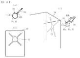
図4(c)に示すように、識別部材39は、ベース部材40と、ベース部材40に取り付けた光学部材38と、取付部41とで構成される。
As shown in FIG. 4C, the
図3に示すように、ベース部材40は、対向二面を正方形とした四角柱状をなし、光透過性材料、例えばアクリル樹脂、ポリカーボネート樹脂、ポリスチレン樹脂などのプラスチックや、ガラスなどで形成される。ベース部材40の前記対向二面を除く四つの側面のうち、いずれか一面には、光学部材38が適宜の手段で装着される。光学部材38は、入射した光のうち所定量の光を透過して残りの光を反射するハーフミラーHMで構成する。なお、前記光透過性材料には空気も含まれる。従って、ベース部材40を、光学部材38の装着面以外の面に開口させた中空状に形成しても良い。
As shown in FIG. 3, the
ベース部材40のうち、前記対向二面の一方には、トナーカートリッジ36に収容するトナー色に対応したシールSを貼付することができる。このシールSにより、ユーザーがトナーカートリッジ36に収容されたトナー色を認識することが可能となる。
A seal S corresponding to the toner color accommodated in the
図4(c)に示すように、取付部41はベース部材40の前記対向二面の他方に設けられる。取付部41は、円柱状の基部41aと基部41aの半径方向に突出するリブ部41bとからなる。取付部41は、ベース部材40と一体形成する他、ベース部材40に適宜の手段で取り付けた別部材とすることもできる。
As shown in FIG. 4C, the
図4(b)に示すように、トナーカートリッジ36には、取付部41と嵌合する嵌合孔42が形成される。嵌合孔42は、基部41aに対応する円形部と、リブ部41bに対応する切欠き部42bとからなる。切欠き部42bは、円形部42aの円周方向複数個所に等間隔で設けられている。切欠き部42bの数は、トナーカートリッジ36の色数と同数とし、本実施形態では、90度毎に等間隔で四箇所に設けた場合を例示している。
As shown in FIG. 4B, the
図4(c)に示すように、トナーカートリッジ36への識別部材39の取り付けは、取付部41を嵌合孔42に嵌合することにより行う。その際、取付部41の基部41aを嵌合孔42の円形部42aに嵌合する一方で、取付部41のリブ部41bをいずれか一つの切欠き部42bに嵌合する。リブ部41bの嵌合先を4つの切欠き部42bの中から適宜選択することで、識別部材39を、回転軸Oを中心とする4つの異なる回転位相角(0°、90°、180°、270°)でトナーカートリッジ36に対して位置決めすることができる。識別部材39を嵌合孔42から取り外し、リブ部41bの嵌合相手を異なる切欠き部42bに変えることで、識別部材39の回転位相角を任意に変更することができる。
As shown in FIG. 4C, the
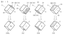
識別部材39の回転位相角は、トナーカートリッジ36の種類、具体的には各カートリッジ36に収容されるトナーの色に応じて定められる。例えば、ブラック(Bk)を0°、シアン(C)を90°、マゼンタ(M)を180°、イエロー(Y)を270°の回転位相角に設定する。識別部材39の回転位相角をこれらの角度間で切り替えると、光学部材38は、識別部材39の回転軸Oの周囲を移動しながらその姿勢を変化させる。この時、光学部材38は、識別部材39の回転軸Oを中心として回転移動角に応じた回転対称性を持つ。従って、識別部材39の回転位相角とトナーカートリッジ36のトナー色とを関連付けることにより、光学部材38の位置および姿勢も各色に対応した四つの態様の間で切り替えることができる(図6参照)。
The rotational phase angle of the
トナーカートリッジ36に形成する嵌合孔42は、例えばトナー収容部にトナーを再充填するための補給口として用いることができる。これにより、補給口を封止するための別部材が不要となって、部品点数を削減することができる。嵌合孔42の周辺にゴムや発泡ウレタンのような気密性シール材を配置し、取付部41をシール材に密着させて、トナーカートリッジ36内部を密閉することが好ましい。トナーカートリッジ36から識別部材39を取り外し、嵌合孔42よりトナーを充填してから、再び識別部材39を嵌合孔42に嵌合することにより、リサイクルトナーカートリッジを製造することができる。
The
この際、各識別部材39を同形状に形成しておけば、シールSをはがすことにより、識別部材39を各色のトナーカートリッジ36において共用することができる。従って、トナーカートリッジ36のリサイクルが可能となる。
At this time, if the
識別部材39には、後述する発光部から光が入射する。ここで、図5に示すように、光学部材38をハーフミラーで構成した場合、光学部材38に光が入射されると、光の一部が反射光となり、残りの光が光学部材38を透過する透過光となる。光の入射角θを一定として、ハーフミラーHMの透過率を50%とした場合、光強度100の入射光に対して、反射光および透過光の光強度はそれぞれ50となる。
Light enters the
次に、図6〜図8に基づいて、本発明にかかるカートリッジ検知機構の各実施形態を説明する。 Next, each embodiment of the cartridge detection mechanism according to the present invention will be described with reference to FIGS.
〔第1実施形態〕
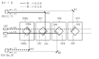
図6は、本発明にかかる検知機構の第1実施形態を示す概略図である。この実施系形態の検知機構は、光学部材38、発光部LD、受光部PD、およびミラーM(反射率100%)をそれぞれに有する2系統の光学系(第一の光学系および第二の光学系)で構成される。
[First Embodiment]
FIG. 6 is a schematic diagram showing a first embodiment of a detection mechanism according to the present invention. The detection mechanism according to this embodiment includes two optical systems (first optical system and second optical system) each including an
各トナーカートリッジ36は、画像形成装置本体の図示しない受け部に着脱可能に装着される。トナーカートリッジ36の配置順序は、識別部材39を回転させて回転位相角を順次大きくした際に、各回転位相角に対応するトナー色の出現順序に準じており、本実施形態では、発光部LD側から、ブラック(Bk)、シアン(C)、マゼンタ(M)、イエロー(Y)の順に各色トナーカートリッジ36が配置されている。
Each
各識別部材39は、図4(c)に示す回転軸Oを発光部LDの入光方向と直交する方向(紙面鉛直方向)に向けて、各色に対応付けられた所定の回転位相角でトナーカートリッジ36Bk,36C,36M,36Yにそれぞれ装着されている。
Each
本実施形態において、第一の光学系(実線で示す)は、第一の発光部LD1と、二つの光学部材38(例えば二段目および三段目の光学部材38C,38M)と、二つの受光部PD1,PD2と、複数のミラーM1,M2とを含む光学系である。また、第二の光学系(破線で示す)は、第二の発光部LD2と、残りの二つの光学部材38(一段目および四段目の光学部材38Bk,38Y)と、二つの受光部PD3,PD4と、複数のミラーM3,M4とを含む光学系である。
In the present embodiment, the first optical system (shown by a solid line) includes a first light emitting unit LD1, two optical members 38 (for example, second and third stage
第一の発光部LD1と第二の発光部LD2は、投光方向を平行にして画像形成装置本体の適所に配置される。第一の発光部LD1の光路上に第一の光学系の二つの光学部材38C,38Mが配置され、第二の発光部LD2の光路上に、第二の光学系の二つの光学部材38Bk,38Yが配置されている。各姿勢の光学部材38に対する光の入射角はいずれも等しく、本実施形態では45°の入射角になっている。
The first light emitting unit LD1 and the second light emitting unit LD2 are arranged at appropriate positions in the image forming apparatus main body with the light projecting directions parallel to each other. Two
各発光部LD1、LD2は、直進性の高い光、例えばレーザ光を照射する光源(レーザダイオード等)で構成される。この発光部LD1,LD2として、各感光体ドラム32を露光させる露光部2の光源を使用することもできる。
Each of the light emitting units LD1 and LD2 includes a light source (laser diode or the like) that irradiates light with high straightness, for example, laser light. As the light emitting portions LD1 and LD2, the light source of the
受光部PD1〜PD4は、光電変換素子を有する半導体素子、例えばフォトダイオード等からなる受光センサで構成される。各受光部PD1〜PD4は、発光部LDと同様に、いずれも画像形成装置本体の適所に装着されている。この実施形態における各受光部PD1〜PD4は、受光の有無のみを検知できるものであれば足り、受光強度を検知する必要はない。そのため、安価な受光センサを使用することができる。 The light receiving portions PD1 to PD4 are configured by a light receiving sensor including a semiconductor element having a photoelectric conversion element, such as a photodiode. Each of the light receiving portions PD1 to PD4 is mounted at an appropriate position of the image forming apparatus main body, like the light emitting portion LD. The light receiving portions PD1 to PD4 in this embodiment need only be capable of detecting the presence or absence of light reception, and do not need to detect the light reception intensity. Therefore, an inexpensive light receiving sensor can be used.
各識別部材39に設けた光学部材38Bk,38C,38M,38Yは、いずれもハーフミラーで構成される。各識別部材39Bk,39C,39M,39Yは同一平面上に配置するのが望ましい。これにより、検知機構全体の構成を薄型化すると共に、光学系の構成を簡略化することができる。
Each of the optical members 38Bk, 38C, 38M, and 38Y provided in each
以上に述べた検知機構においては、図6に示すように、第一の発光部LD1から出射した光は、第一の光学系の前段の光学部材38C(第一の前段光学部材)に入射し、反射光と透過光からなる二種類の通過光に分けられる。このうちの反射光は、ミラーM1で光路を変更した上で第一の受光部PD1に受光される。一方、透過光は、第一の光学系の後段の光学部材38M(第一の後段光学部材)に入射し、透過光と反射光からなる二つの通過光に分けられる。この二種類の通過光のうち、反射光は、ミラーM2で光路を90度変更した上で、第二の受光部PD2に受光される。透過光は、イエロー(Y)の識別部材39のベース部材40を透過する。
In the detection mechanism described above, as shown in FIG. 6, the light emitted from the first light emitting portion LD1 is incident on the
また、第二の光学系においても同様に、第二の発光部LD2から出射した光は、第二の光学系の前段の光学部材38Bk(第二の前段光学部材)に入射し、反射光と透過光からなる二つの通過光に分けられる。この時、第二の発光部LD2は、第一の発光部LD1と同時に発光させることができる。反射光は、ミラーM3で光路を90度変更して第三の受光部PD3に受光される。第二の前段光学部材38Bkを経た透過光は、第二の光学系の後段の光学部材38Y(第二の後段光学部材)に入射し、透過光と反射光からなる二つの通過光に分けられる。この二種類の通過光のうち、反射光がミラーM4で光路を変更して第四の受光部PD4で受光され、透過光はイエロー(Y)の識別部材39Yのベース部材40を透過する。
Similarly, in the second optical system, the light emitted from the second light emitting unit LD2 is incident on the optical member 38Bk (second front optical member) on the front stage of the second optical system, and the reflected light and It is divided into two passing lights composed of transmitted light. At this time, the second light emitting unit LD2 can emit light simultaneously with the first light emitting unit LD1. The reflected light is received by the third light receiving unit PD3 by changing the optical path by 90 degrees by the mirror M3. The transmitted light that has passed through the second front-stage optical member 38Bk is incident on the rear-stage
各受光部PD1〜PD4の受光信号は、図示しない制御装置に入力される。全ての受光部PDで受光されたことを検知すれば、制御装置は、全てのトナーカートリッジ36Bk,36C,36M,36Yが正常に装着されたと判定する。 The light reception signals of the light receiving portions PD1 to PD4 are input to a control device (not shown). If it is detected that light is received by all the light receiving parts PD, the control device determines that all the toner cartridges 36Bk, 36C, 36M, 36Y are normally mounted.
各トナーカートリッジ36Bk,36C,36M,36Yのいずれかが未装着の状態、あるいはいずれかのトナーカートリッジの識別部材39が外れた状態では、発光部LDから出射される光が、未装着等のカートリッジに対応する光学部材38で反射されないため、対応する受光部PDは光を検知しない。また、誤装着により異なる色のトナーカートリッジ36が装着された場合は、誤装着にかかるトナーカートリージの光学部材38により、光が規定外の方向に反射されるため、同様に対応する受光部PDでは受光を検知しない。
In a state where any one of the toner cartridges 36Bk, 36C, 36M, and 36Y is not mounted, or in a state where the
このように、いずれかの受光部PDが受光を検知しない場合は、制御装置は、当該受光部PDに対応するトナーカートリッジ36が未装着あるいは誤装着等の装着不良の状態にあると判定する。
As described above, when any of the light receiving portions PD does not detect light reception, the control device determines that the
以上に述べた判定結果を、制御装置から適当な表示手段に送信する。表示手段Uとしては、例えばブラック(Bk)、シアン(C)、マゼンタ(M)、イエロー(Y)の各色について、装着不良の有無を表示する4つのランプを設けることが考えられる(図7(b)参照)。各色のランプを、例えば正常装着であれば点灯させ、装着不良であれば消灯することで、ユーザーはどの色のカートリッジ36で装着不良が生じたのかを了知させることができる。制御装置は、全てのトナーカートリッジ36Bk,36C,36M,36Yが正常装着されていると判定すれば、画像形成動作を開始する。その一方、少なくともいずれか一色のトナーカットリッジ36Bk,36C,36M,36Yで装着不良があれば、画像形成装置1を強制的に停止させ、さらに必要に応じてユーザー向けに警報(アラート)を報知する。なお、表示手段の構成は任意であり、上記のようにランプを使用する他、液晶表示を採用することもできる。
The determination result described above is transmitted from the control device to appropriate display means. As the display means U, for example, it is conceivable to provide four lamps for displaying the presence / absence of defective mounting for each color of black (Bk), cyan (C), magenta (M), and yellow (Y) (FIG. 7 ( b)). By turning on the lamps of the respective colors, for example, if they are normally mounted, and turning them off if they are not mounted correctly, the user can know which
図7(a)にトナーカートリッジ36の装着状態、受光部PDでの検知結果、表示手段での表示パターンの一覧表を示す。「装着状態」の欄は、各トナーカートリッジ36が正しく装着されているか否かを表し、正しく装着されている状態を○で、未装着または誤装着の状態を×で示す。また、「PD検知」の欄は、各受光部PDでの受光の有無を表し、受光を検知した場合を1で、未検知の場合を0で示す。また、「表示パターン」は、表示手段でのランプのON/OFF状態を示す。
FIG. 7A shows a list of the mounting state of the
図7(a)からも明らかなように、本発明の検知機構であれば、個々のトナーカートリッジ毎に装着不良の有無を判定することができ、各トナーカートリッジ36Bk,36C,36M,36Yで生じる装着不良の有無のあらゆる組合せに対しても確実に検知することができる。 As apparent from FIG. 7A, the detection mechanism of the present invention can determine the presence or absence of defective mounting for each individual toner cartridge, and occurs in each of the toner cartridges 36Bk, 36C, 36M, and 36Y. Any combination of whether or not there is a mounting failure can be reliably detected.
この際、トナーカートリッジ毎の装着不良の有無を光学的に検知する構造であるので、トナーカートリッジ(特に非正規のトナーカートリッジ)を強制装着した際にも、部材の形状差から機械的に装着不良の有無を判定する構成で問題となる、トナーカートリッジや画像形成装置本体での破損を生じにくい。 At this time, since it is configured to optically detect the presence / absence of a mounting failure for each toner cartridge, even when a toner cartridge (particularly a non-regular toner cartridge) is forcibly mounted, it is mechanically mounted due to the difference in shape of the member Damage to the toner cartridge and the image forming apparatus main body, which is a problem in the configuration for determining the presence or absence of toner, is unlikely to occur.
また、発光部LDおよび受光部PDがいずれも画像形成装置本体側に設けられているため、トナーカートリッジ交換時に発光部LDや受光部PDを交換する必要がなく、メンテナンスコストを抑制することができる。 In addition, since both the light emitting unit LD and the light receiving unit PD are provided on the image forming apparatus main body side, it is not necessary to replace the light emitting unit LD and the light receiving unit PD when replacing the toner cartridge, and the maintenance cost can be suppressed. .
さらに、二つの光学系のそれぞれに、前段の光学部材38C,38Bkと、後段の光学部材38M,38Yとを配置し、ハーフミラーからなる前段の光学部材38C,38Bkを経た透過光を、後段の光学部材38M,38Yに入射させているため、それぞれの光学系で、一つの発光部LDから二つの通過光を得て、それぞれ受光部PDで受光させることができる。そのため、発光部LDの数をトナーカートリッジ36の種類数よりも削減(半減)することができる。これにより、検知機構全体の発光部LDの数を少なくして、低コスト化を図ることができる。
Further, in each of the two optical systems, the front
以上に述べた実施形態では、各光学部材38Bk,38C,38M,38Yを経た通過光(反射光もしくは透過光)のうち、反射光を受光部PD1〜PD4で受光するようにしているが、ミラーM1〜M4の配置や数を変更することで、受光部PD1〜PD4の一部または全部で、各光学部材38を経た透過光を受光するように構成することもできる。この場合、前段光学部材38Bk,38Cの反射光を、後段光学部材38M,38Yに入射させる。各光学部材38を構成するハーフミラーとしては、透過率50%のものに限らず、任意の透過率のものを使用することができる。
In the embodiment described above, among the passing light (reflected light or transmitted light) that has passed through the optical members 38Bk, 38C, 38M, and 38Y, the reflected light is received by the light receiving portions PD1 to PD4. By changing the arrangement and number of M1 to M4, a part or all of the light receiving portions PD1 to PD4 can be configured to receive the transmitted light that has passed through the
各光学系の後段光学部材38M,38Yは、全反射を行う反射部材(ミラー)で構成することもできる。
The latter stage
〔第2実施形態〕
図8および図9に本発明にかかる検知機構の第2実施形態を示す。第1実施形態では、各光学部材38Bk,38C,38M,38Yを経た通過光を、それぞれに対応した一つの受光部PD1〜PD4で受光している。これに対し、第2実施形態では、前段の光学部材38Bk,38Cと後段の光学部材38M,38Yとで受光部PDを一部共用化し、一つの受光部PDでどちらか一方の前段光学部材(38Bk,38Cのどちらか一方)の通過光と、どちらか一方の後段光学部材(38M,38Yのどちらか一方)の通過光とを受光するようにしている。
[Second Embodiment]
8 and 9 show a second embodiment of the detection mechanism according to the present invention. In the first embodiment, the light passing through each of the optical members 38Bk, 38C, 38M, and 38Y is received by one of the light receiving portions PD1 to PD4 corresponding to each. On the other hand, in the second embodiment, the front optical members 38Bk and 38C and the rear
この第2実施形態では、二つの受光部PD1,PD2が設置される。第一の受光部PD1が異なる光学系に属する前段光学部材と後段光学部材の各反射光を受光し、第二の受光部PD2も異なる光学系に属する前段光学部材と後段光学部材の各反射光を受光するようになっている。具体的には、第一の受光部PD1が、第二の光学系の前段光学部材38Bk(第二の前段光学部材)の反射光と、第一の光学系の後段光学部材38M(第一の後段光学部材)の反射光とを受光し、第二の受光部PD2が、第一の光学系の前段光学部材38C(第一の前段光学部材)の反射光と、第二の光学系の後段光学部材38Y(第二の後段光学部材)の反射光とを受光するように各ミラー1〜4が配置されている。
In the second embodiment, two light receiving parts PD1 and PD2 are installed. The first light receiving unit PD1 receives the reflected light of the front optical member and the rear optical member belonging to different optical systems, and the second light receiving unit PD2 also receives the reflected light of the front optical member and the rear optical member belonging to different optical systems. Light is received. Specifically, the first light receiving section PD1 includes the reflected light of the second optical system front optical member 38Bk (second front optical member) and the first optical system rear
各光学部材38Bk,38C,38M,38Yはハーフミラーで構成される。各ハーフミラーの透過率が50%であることから、発光部LDの光強度を100とした場合、前段光学部材38Bk,36Cを経た反射光の光強度は50となり、後段の光学部材38M,38Yを経た反射光の光強度は25となる。
Each optical member 38Bk, 38C, 38M, 38Y is formed of a half mirror. Since the transmittance of each half mirror is 50%, when the light intensity of the light emitting part LD is 100, the light intensity of the reflected light that has passed through the front optical members 38Bk, 36C is 50, and the
この場合において、第一の受光部PD1での受光強度を場合分けして考えると、前段光学部材38Bkおよび後段光学部材38Mのそれぞれに対応するトナーカートリッジ36Bk,36Mが正常装着されていれば、第一の受光部PD1の受光強度は75となる(50+25)。前段光学部材38Bkに対応するトナーカートリッジ36Bkが正常装着される一方、後段光学部材38Mに対応するトナーカートリッジ36Mに装着不良があれば、第一の受光部PD1の受光強度は50となり、正常装着と装着不良の関係が逆の場合は第一の受光部PD1の受光強度は25となる。双方のトナーカートリッジ36Bk,36Mに装着不良があれば第一の受光部PD1の受光強度は0となる。
In this case, when the received light intensity at the first light receiving portion PD1 is considered separately, if the toner cartridges 36Bk and 36M corresponding to the front optical member 38Bk and the rear
従って、第一の受光部PD1として、75,50,25,0の4段階の受光強度を判別できるものを使用すれば、二つのトナーカートリッジ36Bk,36Mで生じる正常装着・装着不良のあらゆる組合せを検知することが可能となる。第二の受光部PD2においても同様に、二つのトナーカートリッジ36C,36Yの正常装着・装着不良の組合せに応じて、75,50,25,0の4段階の受光強度が生じる。そのため、第二の受光部PD2として4段階の受光強度を判別できるものを使用すれば、二つのトナーカートリッジ36C,36Yで生じる正常装着・装着不良のあらゆる組合せを検知することが可能となる。
Therefore, if the first light receiving part PD1 is capable of discriminating the received light intensity in four stages of 75, 50, 25, and 0, any combination of normal mounting and mounting defects occurring in the two toner cartridges 36Bk and 36M can be obtained. It becomes possible to detect. Similarly, in the second light receiving unit PD2, four levels of received light intensity of 75, 50, 25, and 0 are generated according to the combination of normal mounting and mounting failure of the two
図9(a)に、第2実施形態における各トナーカートリッジ36の装着状態、各受光部PDでの検知結果、表示手段での表示パターンの一覧表を示す。同図からも明らかなように、各受光部PD1,PD2の受光強度が4段階のどのレベルであるかを認識することで、各トナーカートリッジ36Bk,36C,36M,36Yで生じる正常装着および装着不良のあらゆる組合せに対し、個々のトナーカートリッジ36Bk,36C,36M,36Yの装着状態を判定することができる。この判定結果を表示手段Uで表示することで、ユーザーに個々のトナーカートリッジの装着状態を了知させることができる。
FIG. 9A shows a list of the mounted state of each
なお、ブラック(Bk)とイエロー(Y)のトナーカートリッジ36Bk,36Yに装着不良があり、他のトナーカットリッジ36C,36Mが正常装着されていると仮定した場合、各受光部PD1,PD2での受光強度は図9(b)に示すとおりである。また、図9(c)にこの場合の表示手段Uでの表示パターンを示す(白塗りが点灯、黒塗りが消灯を表す)。
If it is assumed that the black (Bk) and yellow (Y) toner cartridges 36Bk and 36Y are defectively mounted and the other toner cut
この第2実施形態でも、基本的に上記第1実施形態と同様の作用効果が得られる。加えて第2実施形態によれば、第一の光学系と第二の光学系の間で受光部PDを共用しているので、第1実施形態に比べて受光部PDの数を削減(半減)できるという作用効果も得られる。 In the second embodiment, basically the same effects as those in the first embodiment can be obtained. In addition, according to the second embodiment, since the light receiving parts PD are shared between the first optical system and the second optical system, the number of light receiving parts PD is reduced compared to the first embodiment (halved). ) Can also be obtained.
なお、この第2実施形態でも、第1実施形態と同様に、ミラーM1〜M4の配置や数を変更することで、受光部PD1,PD2のどちらか一方または双方で、各光学部材38を経た透過光を受光することもできる。この場合、前段光学部材38Bk,38Cの反射光を、後段光学部材38M,38Yに入射させる。
In the second embodiment, similarly to the first embodiment, the arrangement and the number of mirrors M1 to M4 are changed so that one or both of the light receiving parts PD1 and PD2 pass through each
また、各光学部材38を構成するハーフミラーとしては、透過率50%のものに限らず、任意の透過率のものを使用することもできる。ハーフミラーとして、透過率50%以外のものを使用する場合には、各光学系の後段光学部材38M,38Yを、全反射を行う反射部材(ミラー)で構成することもできる。
Moreover, as a half mirror which comprises each
また、図8の構成では、二つの受光部PD1,PD2のそれぞれで、前段光学部材と後段光学部材の反射光を受光する際に、異なる光学系の反射光を受光するようにしている。これに対し、ミラーMの配置や数を変更することにより、二つの受光部PD1,PD2のそれぞれで、同じ光学系の前段光学部材と後段光学部材の反射光を受光するように構成することもできる(例えば、第一の受光部PD1で第一の光学系の前段光学部材38Cと後段光学部材38Mの反射光を受光し、第二の受光部PD2で第二の光学系の前段光学部材38Bkと後段光学部材38Yの反射光を受光する。図10(a)(b)参照)。
Further, in the configuration of FIG. 8, when the reflected light of the front optical member and the rear optical member is received by each of the two light receiving portions PD1 and PD2, the reflected light of different optical systems is received. On the other hand, by changing the arrangement and number of mirrors M, each of the two light receiving parts PD1 and PD2 may be configured to receive the reflected light of the front optical member and the rear optical member of the same optical system. (For example, the first light receiving portion PD1 receives the reflected light of the front
〔第3実施形態〕
図10および図11に、本発明にかかる検知機構の第3実施形態を示す。第2実施形態では、第一の発光部LD1と第二の発光部LD2を同時に発光させたが、第3実施形態では、第一の光学系の第一発光部LD1と、第二の光学系の第二発光部LD2とを時間差をもって発光させるようにしている。
[Third Embodiment]
10 and 11 show a third embodiment of the detection mechanism according to the present invention. In the second embodiment, the first light emitting part LD1 and the second light emitting part LD2 are caused to emit light at the same time. However, in the third embodiment, the first light emitting part LD1 of the first optical system and the second optical system. The second light emitting part LD2 is caused to emit light with a time difference.
この実施形態の検知機構全体で、一つの受光部PD1が設置される。第一の受光部PD1は、まず、一方の光学系(第一の光学系)に属する前段光学部材と後段光学部材との反射光を受光し、これに引き続いて、他の光学系(第二の光学系)に属する前段光学部材と後段光学部材との各反射光を受光する。具体的には、まず、第一の受光部PD1が、第一の光学系の前段光学部材38C(第一の前段光学部材)と後段光学部材38M(第一の後段光学部材)の各反射光とを受光し、これに引き続いて、第一の受光部PD1が、第二の光学系の前段光学部材38Bk(第二の前段光学部材)と後段光学部材38Y(第二の後段光学部材)の各反射光とを受光する。これを実現できるように、各ミラーM1〜M8が配置されている。
In the entire detection mechanism of this embodiment, one light receiving unit PD1 is installed. The first light receiving unit PD1 first receives the reflected light from the front optical member and the rear optical member belonging to one optical system (first optical system), and subsequently receives the other optical system (second optical system). Each reflected light of the front optical member and the rear optical member belonging to the optical system) is received. Specifically, first, the first light-receiving unit PD1 reflects each reflected light of the front
この実施形態では、図10(a)に示すように、まず、第一の光学系の第一発光部LD1を発光し、第一の光学系の前段光学部材38Cおよび後段光学部材38Mの反射光を受光部PD1で受光する。この時、受光部PD1では、第2実施形態と同様に、二つのトナーカートリッジ36C,36Mの正常装着・装着不良の組合せに応じて、75,50,25,0の4段階の受光強度が生じる。従って、受光部PD1として、この4段階の受光強度を判別できるものを使用することにより、二つのトナーカートリッジ36C,36Mで生じる正常装着・装着不良のあらゆる組合せを検知することができる。
In this embodiment, as shown in FIG. 10A, first, the first light emitting portion LD1 of the first optical system emits light, and the reflected light of the front
次に、図10(b)に示すように、第一の発光部LD1を消灯すると共に、第二の光学系の第二発光部LD2を発光させ、第二の光学系の前段光学部材38Bkおよび後段光学部材38Yの反射光を受光部PD1で受光する。これにより、残りの二つのトナーカートリッジ36Bk,36Yで生じる正常装着・装着不良のあらゆる組合せを検知することができる。図11(b)に示すように、第一の発光部LD1と第二の発光部LD2を交互に繰り返し発光させることで、装着不良の有無を複数回判定することができ、判定精度が向上する。
Next, as shown in FIG. 10 (b), the first light emitting part LD1 is turned off and the second light emitting part LD2 of the second optical system is caused to emit light, and the front optical member 38Bk of the second optical system and The reflected light of the rear
図11(a)に、第3実施形態における各トナーカートリッジ36の装着状態、受光部PDでの検知結果、表示手段での表示パターンの一覧表を示す。上記のように、第一の光学系での検知と、第二の光学系での検知とが時間差をもって行われるため、先の検知工程での検知結果を制御装置で記憶しておき、後の検知結果と照合することで、各トナーカートリッジ36Bk,36C,36M,36Yで生じる正常装着および装着不良のあらゆる組合せを認識し、個々のトナーカートリッジ36Bk,36C,36M,36Yについて、その装着状態の良否を判定することができる。この判定結果を表示手段Uで表示することで、ユーザーに個々のトナーカートリッジの装着状態を了知させることができる。
FIG. 11A shows a list of the mounting states of the
なお、一例として、図11(b)に、シアン(C)とイエロー(Y)のトナーカートリッジ36C,36Yに装着不良があり、他のトナーカットリッジ36Bk,36Mが正常装着されている場合の受光部PD1での受光強度を示し、図11(c)にこの場合の表示手段Uでの表示パターンを示す(白塗りが点灯、黒塗りが消灯を表す)。
As an example, in FIG. 11B, light reception when cyan (C) and yellow (Y)
この第3実施形態でも、基本的に上記第2実施形態と同様の作用効果が得られる。加えて第3実施形態によれば、第一の光学系の第一発光部LD1と、第二の光学系の第二発光部LD2とを時間差をもって発光させるようにしているので、第一の光学系と第二の光学系とで同じ受光部PDを共用できる。そのため、第2実施形態に比べて受光部PDの数を削減(半減)できるという作用効果も得られる。 Also in the third embodiment, basically the same effects as those of the second embodiment can be obtained. In addition, according to the third embodiment, the first light emitting unit LD1 of the first optical system and the second light emitting unit LD2 of the second optical system are caused to emit light with a time difference. The same light receiving part PD can be shared by the system and the second optical system. Therefore, the effect that the number of light receiving parts PD can be reduced (halved) as compared with the second embodiment is also obtained.
なお、この第3実施形態でも、第2実施形態と同様に、ミラーM1〜M8の配置や数を変更することで、受光部PD1で、各光学部材38を経た透過光を受光することもできる。この場合、前段光学部材38Bk,38Cの反射光を、後段光学部材38M,38Yに入射させる。
In the third embodiment, similarly to the second embodiment, the light passing through each
また、各光学部材38を構成するハーフミラーとしては、透過率50%のものに限らず、任意の透過率のものを使用することもできる。ハーフミラーとして、透過率50%以外のものを使用する場合には、各光学系の後段光学部材38M,38Yを、全反射を行う反射部材(ミラー)で構成することもできる。
Moreover, as a half mirror which comprises each
〔第4実施形態〕
図12および図13に、本発明にかかる検知機構の第4実施形態を示す。この実施形態では、第一の光学系と第二の光学系とで同じ発光部LD1を共用し、発光部LD1からの光の照射方向を、可動ミラーM0により、第一の光学系と第二の光学系との間で切り替え可能としている。
[Fourth Embodiment]
12 and 13 show a fourth embodiment of the detection mechanism according to the present invention. In this embodiment, the first optical system and the second optical system share the same light emitting part LD1, and the irradiation direction of light from the light emitting part LD1 is changed between the first optical system and the second optical system by the movable mirror M0. It is possible to switch between these systems.
可動ミラーM0は、図12(a)に示すように、発光部LD1の光路外に退避させた状態(位置A)と、図12(b)に示すように、発光部LD1の光路上に配置した状態(位置B)との間で切り替え可能に構成する。この可動ミラーM0の切り替えは、例えば図示しないモータ等の駆動機構で可動ミラーM0を揺動させることで行うことができる。 As shown in FIG. 12A, the movable mirror M0 is disposed outside the light path of the light emitting unit LD1 (position A) and disposed on the light path of the light emitting unit LD1 as shown in FIG. 12B. It is possible to switch between the state (position B). The switching of the movable mirror M0 can be performed, for example, by swinging the movable mirror M0 by a drive mechanism such as a motor (not shown).
本実施形態の検知機構では、二つの受光部PD1,PD2が設置される。第2実施形態と同様に、第一の受光部PD1は異なる光学系に属する前段光学部材と後段光学部材の反射光を受光し、第二の受光部PD2も異なる光学系に属する前段光学部材と後段光学部材の反射光を受光する。具体的には、第一の受光部PD1が、第二の光学系の前段光学部材38Bkの反射光と第一の光学系の後段光学部材38Mの反射光とを受光し、第二の受光部PD2が、第一の光学系の前段光学部材38Cの反射光と第二の光学系の後段光学部材38Yの反射光とを受光するように各ミラーM1〜M4が配置されている。
In the detection mechanism of the present embodiment, two light receiving parts PD1 and PD2 are installed. Similarly to the second embodiment, the first light receiving unit PD1 receives the reflected light of the front optical member and the rear optical member belonging to different optical systems, and the second light receiving unit PD2 also includes the front optical member belonging to different optical systems. The reflected light of the latter optical member is received. Specifically, the first light receiving unit PD1 receives the reflected light of the front optical member 38Bk of the second optical system and the reflected light of the rear
図12(a)に示すように、可動ミラーM0を発光部LD1の光路外に配置した状態で発光部LD1を発光させると、発光部LD1の光は、第一の光学系の前段光学部材38Cおよび後段光学部材38Mに入射し、前者の反射光が第二の受光部PD2に、後者の反射光が第一の受光部PD1に受光される。次いで、図12(b)に示すように、可動ミラーM0を発光部LD1の光路上に配置し、その状態で発光部LD1を発光させると、発光部LD1の光は、第二の光学系の前段光学部材38Bkおよび後段光学部材38Yに入射し、前者の反射光が第一の受光部PD1に、後者の反射光が第二の受光部PD2に受光される。
As shown in FIG. 12A, when the light emitting unit LD1 emits light with the movable mirror M0 disposed outside the light path of the light emitting unit LD1, the light of the light emitting unit LD1 is emitted from the front
この場合、第一の受光部PD1は、第二の光学系の前段光学部材38Bkの反射光と、第一の光学系の後段光学部材38Mの反射光とを時間差をもって受光する。また、第二の受光部PD2は、第一の光学系の前段光学部材38Cの反射光と第二の光学系の後段光学部材38Yの反射光とを時間差をもって受光する。この場合、第一および第二の受光部PD1,PD2は、それぞれ前段光学部材の反射光と後段光学部材の反射光とを時間差をもって受光する。そのため、第一および第二の受光部PD1,PD2は、第2および第3の実施形態のように、複数段階の受光強度を判別する必要はなく、受光の有無を検知できるものであれば足りる。従って、安価な受光センサを使用することができる。
In this case, the first light receiving unit PD1 receives the reflected light of the front optical member 38Bk of the second optical system and the reflected light of the rear
図13に、以上に述べた第4実施形態における各トナーカートリッジ36の装着状態、受光部PDでの検知結果、表示手段での表示パターンの一覧表を示す。上記のように、第一の光学系での装着状態の検知と、第二の光学系での装着状態の検知とが可動ミラーM0の切り替えにより時間差をもって行われるため、先の検知結果を制御装置で記憶しておき、後の検知結果と照合することで、4つの各トナーカートリッジ36Bk,36C,36M,36Yで生じる正常装着および装着不良のあらゆる組合せを認識し、個々のトナーカートリッジ36Bk,36C,36M,36Yについて、その装着状態の良否を判定することができる。この判定結果を表示手段Uで表示することで、ユーザーに個々のトナーカートリッジの装着状態を了知させることができる。
FIG. 13 shows a list of the mounting states of the
なお、一例として、図13(b)に、シアン(C)とイエロー(Y)のトナーカートリッジ36C,36Yに装着不良があり、他のトナーカットリッジ36Bk,36Mが正常装着されている場合の受光部PD1,PD2での受光強度を示し、図13(c)にこの場合の表示手段Uでの表示パターンを示す(白塗りが点灯、黒塗りが消灯を表す)。
As an example, in FIG. 13B, light reception when cyan (C) and yellow (Y)
この第4実施形態でも、基本的に上記第2および第3実施形態と同様の作用効果が得られる。加えて第4実施形態によれば、発光部LD1からの光の入射方向を、第一の光学系と第二の光学系との間で切り替えるようにしているので、第一の光学系と第二の光学系とで発光部LDを共用することができる。そのため、検知機構全体の発光部LDの数をさらに削減(半減)させ、一つにすることができる。 Also in the fourth embodiment, basically the same effects as those of the second and third embodiments can be obtained. In addition, according to the fourth embodiment, the incident direction of the light from the light emitting unit LD1 is switched between the first optical system and the second optical system. The light emitting part LD can be shared by the second optical system. Therefore, the number of light emitting parts LD in the entire detection mechanism can be further reduced (halved) to one.
第4実施形態では、各光学部材38Bk,38C,38M,38Yを経た通過光のうち、反射光を受光部PD1,PD2で受光するようにしているが、ミラーM1〜M4の配置や数を変更することで、受光部PD1,PD2で、各光学部材38を経た透過光を受光することもできる。この場合、前段光学部材38Bk,38Cの反射光を、後段光学部材38M,38Yに入射させる。
In the fourth embodiment, the reflected light is received by the light receiving portions PD1 and PD2 among the light passing through the optical members 38Bk, 38C, 38M, and 38Y. However, the arrangement and number of the mirrors M1 to M4 are changed. As a result, the light receiving parts PD1 and PD2 can also receive the transmitted light that has passed through the
各光学部材38を構成するハーフミラーとしては、透過率50%のものに限らず、任意の透過率のものを使用することができる。
The half mirrors constituting each
また、各光学系の後段光学部材38M,38Yは、全反射を行う反射部材(ミラー)で構成することもできる。
Further, the rear
〔第5実施形態〕
図14および図15に、本発明にかかる検知機構の第5実施形態を示す。この実施形態では、第4実施形態と同様に、発光部LD1からの光の照射方向を、可動ミラーM0により、第一の光学系と第二の光学系との間で切り替えることで、第一の光学系による装着状態の検知と、第二の光学系による装着状態の検知とを時間差をつけて行うようにしている。
[Fifth Embodiment]
14 and 15 show a fifth embodiment of the detection mechanism according to the present invention. In this embodiment, as in the fourth embodiment, the irradiation direction of light from the light emitting unit LD1 is switched between the first optical system and the second optical system by the movable mirror M0, so that the first The detection of the mounting state by the optical system and the detection of the mounting state by the second optical system are performed with a time difference.
この第5実施形態では、機構全体で一つの受光部PD1を設置している点が第4実施形態と異なる。具体的には、第一の光学系の前段光学部材38Cの反射光、第一の光学系の後段光学部材38Mの反射光、第二の光学系の前段光学部材38Bkの反射光、および第二の光学系の後段光学部材38Yの反射光が、いずれも一つの受光部PD1で受光されるように各ミラーM1〜M8が配置されている。
The fifth embodiment is different from the fourth embodiment in that one light receiving unit PD1 is installed in the entire mechanism. Specifically, the reflected light of the front
図14(a)に示すように、可動ミラーM0を揺動させて発光部LD1の光路外に配置し(位置A)、その状態で発光部LD1を発光させると、発光部LD1の光は、第一の光学系の前段光学部材38Cおよび後段光学部材38Mに入射し、双方の反射光が受光強度差をもって受光部PD1に受光される。次いで、図14(b)に示すように、可動ミラーM0を発光部LD1の光路上に配置し(位置B)、その状態で発光部LD1を発光させると、発光部LD1の光は、第二の光学系の前段光学部材38Bkおよび後段光学部材38Yに入射し、双方の反射光が受光強度差をもって同じ受光部PD1に受光される。
As shown in FIG. 14A, when the movable mirror M0 is swung and arranged outside the optical path of the light emitting unit LD1 (position A), and the light emitting unit LD1 emits light in this state, the light of the light emitting unit LD1 is The light enters the front
この時、受光部PD1では、前段の検知工程によって、二つのトナーカートリッジ36C,36Mの正常装着・装着不良の組合せに応じて、75,50,25,0の4段階の受光強度が生じる。同様に後段の検知行程によって、残りのトナーカートリッジ36Bk,36Yの正常装着・装着不良の組合せに応じて、75,50,25,0の4段階の受光強度が生じる。従って、受光部PD1として、この4段階の受光強度を検知できるものを使用することにより、各トナーカートリッジ36Bk,36C,36M,36Yで生じる正常装着・装着不良のあらゆる組合せを検知することができる。
At this time, in the light receiving unit PD1, the light detection intensity in four stages of 75, 50, 25, and 0 is generated according to the combination of the normal mounting and the mounting failure of the two
図15(a)に、第5実施形態における各トナーカートリッジ36の装着状態、受光部PDでの検知結果、表示手段での表示パターンの一覧表を示す。上記のように、第一の光学系での装着状態の検知と、第二の光学系での装着状態の検知とが可動ミラーM0の切り替えにより時間差をもって行われるため、先の検知工程での検知結果を制御装置で記憶しておき、後の工程の検知結果と照合することで、各トナーカートリッジ36Bk,36C,36M,36Yで生じる正常装着および装着不良のあらゆる組合せを認識し、個々のトナーカートリッジ36Bk,36C,36M,36Yについて、その装着状態の良否を判定することができる。この判定結果を表示手段Uで表示することで、ユーザーに個々のトナーカートリッジの装着状態を了知させることができる。
FIG. 15A shows a list of the mounted state of each
なお、一例として、図15(b)にシアン(C)とイエロー(Y)のトナーカートリッジ36C,36Yに装着不良があり、他のトナーカットリッジ36Bk,36Mが正常装着されている場合の受光部PD1での受光強度を示し、図15(c)にこの場合の表示手段Uでの表示パターンを示す(白塗りが点灯、黒塗りが消灯を表す)。
As an example, in FIG. 15B, the light receiving unit when cyan (C) and yellow (Y)
この第5実施形態でも、基本的に上記第4実施形態と同様の作用効果が得られる。加えて第5実施形態によれば、第一の光学系と第二の光学系とで同じ受光部PDを共用し、検知機構全体で受光部PDの数を一つにしているので、第4実施形態に比べて受光部PDの数を削減(半減)できるという作用効果も得られる。 In the fifth embodiment, basically the same operational effects as in the fourth embodiment can be obtained. In addition, according to the fifth embodiment, the first optical system and the second optical system share the same light receiving part PD, and the number of light receiving parts PD is one in the entire detection mechanism. The effect that the number of light receiving parts PD can be reduced (halved) as compared with the embodiment is also obtained.
なお、この第5実施形態でも、第2実施形態と同様に、ミラーM1〜M8の配置や数を変更することで、受光部PD1で、各光学部材38を経た透過光を受光することもできる。この場合、前段光学部材38Bk,38Cの反射光を、後段光学部材38M,38Yに入射させる。
In the fifth embodiment, similarly to the second embodiment, the light passing through each
また、各光学部材38を構成するハーフミラーとしては、透過率50%のものに限らず、任意の透過率のものを使用することができる。ハーフミラーとして、透過率50%以外のものを使用する場合には、各光学系の後段光学部材38M,38Yを、全反射を行う反射部材(ミラー)で構成することもできる。
Moreover, as a half mirror which comprises each
図16に、以上に述べた第1〜第5実施形態における発光部LD、受光部PD、および光路を形成するミラーMの数などのまとめを示す。いずれの実施形態においても、発光部LDの数は、トナーカートリッジ36の数を下回り、また第2実施形態〜第5実施形態では、受光部PDの数がトナーカートリッジ36の数を下回る。そのため、従来のようにトナーカートリッジ36毎に発光部と受光部とを設ける検知機構に比べると、発光部LDや受光部PDの数を減じて、低コスト化を図ることができる。
FIG. 16 shows a summary of the light emitting part LD, the light receiving part PD, the number of mirrors M forming the optical path, and the like in the first to fifth embodiments described above. In any of the embodiments, the number of light emitting units LD is less than the number of
〔識別部材の他の構成例〕
以上の説明では、識別部材39として、対向二面を正方形とする四角柱状部分を有するベース部材40において、四角柱部分の対向二面を除く側面に光学部材38を取り付けた構成を例示したが、識別部材39はこれ以外の形状に形成することもできる。
[Other configuration examples of identification member]
In the above description, as the
図17(a)〜(c)に示す識別部材39は、図4(c)に示す実施形態において、ベース部材40を円柱状に形成して、その外周面の円周方向90°の範囲内に光学部材38を取り付けたものである。基部41aおよびリブ部41bを有する取付部41のうち、基部41aは、ベース部材40と一体かつ同径の円柱状をなしている。トナーカートリッジ36に設けた嵌合孔42は、基部41aに対応する円形部42aと、リブ部41bに対応する4つの切欠き部42bとからなる。
In the embodiment shown in FIG. 4 (c), the
図18(a)〜(c)に示す識別部材39は、図17(a)〜(c)に示す実施形態において、リブ部41bの端面に光学部材38を取り付けたものである。トナーカートリッジ36には、識別部材39の形状に対応した嵌合孔42が形成されている。
In the embodiment shown in FIGS. 17A to 17C, the
以上の説明では、図19(a)に示すように、識別部材39をトナーカートリッジ36の側面に取り付ける場合を例示ししている。識別部材39のトナーカートリッジ36に対する取り付け位置はこれに限らず、各識別部材39の回転軸Oが発光部LDの入光方向と直交する方向である限り任意の位置に取り付けることができる。例えば図19(b)および図20に示すように、トナーカートリッジ36の上面に識別部材39を取り付けることもできる。
In the above description, the case where the
以上、本発明の実施形態について説明したが、本発明は上述の実施形態に限定されるものではなく、本発明の要旨を逸脱しない範囲で種々の変更を加え得ることは勿論である。例えば、検知機構としてトナーカートリッジ36の装着不良を検知する場合を例示したが、この検知機構は、トナーボトルやインクタンク等のカートリッジ、さらにはトナーカートリッジ36と一体化したオールインワン形式の作像ユニット31からなるカートリッジの装着不良の有無を検知する機構として、広く利用することができる。
The embodiment of the present invention has been described above, but the present invention is not limited to the above-described embodiment, and it is needless to say that various modifications can be made without departing from the gist of the present invention. For example, the case where a mounting failure of the
また、画像形成装置は、図1に示すカラー電子写真装置に限らず、モノクロ用等のその他の画像形成装置や、複写機、プリンタ、ファクシミリ、あるいはこれらの複合機などであっても良い。 Further, the image forming apparatus is not limited to the color electrophotographic apparatus shown in FIG. 1, but may be other image forming apparatuses for monochrome or the like, a copying machine, a printer, a facsimile, or a complex machine thereof.
1 画像形成装置
36 トナーカートリッジ(カートリッジ)
38 光学部材
39 識別部材
93 判別手段
LD 発光部
PD 受光部
U 表示手段
M0 可動ミラー
1
38
Claims (13)
カートリッジに光学部材を設け、この光学部材に、画像形成装置本体に設けられた発光部からの光を入射させると共に、光学部材を経た通過光を画像形成装置本体に設けられた受光部で受光し、
二つ以上のカートリッジを備え、光路上に、二つのカートリッジのうち一方のカートリッジに設けられた前段の光学部材と、他方のカートリッジに設けられた後段の光学部材とを配置し、少なくとも前段光学部材を、光の反射と透過とを許容するハーフミラーで構成し、前段光学部材を経た反射光と透過光とのうち、どちらか一方の通過光を後段光学部材に入射させたことを特徴とするカートリッジ検知機構。 A cartridge detection mechanism for detecting a mounting failure of a cartridge attached to and detached from the image forming apparatus main body,
An optical member provided in the cartridge, the optical member, the light is incident from the light emitting portion provided in the image forming apparatus main body, received by the light receiving section provided a transmission light having passed through the optical member in an image forming apparatus main body ,
Two or more cartridges are provided, and a front optical member provided in one of the two cartridges and a rear optical member provided in the other cartridge are arranged on the optical path, and at least the front optical member Is composed of a half mirror that allows reflection and transmission of light, and one of the reflected light and the transmitted light that has passed through the front optical member is incident on the rear optical member. Cartridge detection mechanism.
Priority Applications (1)
| Application Number | Priority Date | Filing Date | Title |
|---|---|---|---|
| JP2011195993A JP5768611B2 (en) | 2011-09-08 | 2011-09-08 | Image forming apparatus |
Applications Claiming Priority (1)
| Application Number | Priority Date | Filing Date | Title |
|---|---|---|---|
| JP2011195993A JP5768611B2 (en) | 2011-09-08 | 2011-09-08 | Image forming apparatus |
Publications (3)
| Publication Number | Publication Date |
|---|---|
| JP2013057800A JP2013057800A (en) | 2013-03-28 |
| JP2013057800A5 JP2013057800A5 (en) | 2014-08-21 |
| JP5768611B2 true JP5768611B2 (en) | 2015-08-26 |
Family
ID=48133735
Family Applications (1)
| Application Number | Title | Priority Date | Filing Date |
|---|---|---|---|
| JP2011195993A Expired - Fee Related JP5768611B2 (en) | 2011-09-08 | 2011-09-08 | Image forming apparatus |
Country Status (1)
| Country | Link |
|---|---|
| JP (1) | JP5768611B2 (en) |
Family Cites Families (6)
| Publication number | Priority date | Publication date | Assignee | Title |
|---|---|---|---|---|
| JP2972617B2 (en) * | 1997-01-23 | 1999-11-08 | 新潟日本電気株式会社 | Image forming device |
| JP4368658B2 (en) * | 2003-10-31 | 2009-11-18 | 株式会社リコー | Image forming apparatus, process cartridge, and developing unit |
| JP2005352228A (en) * | 2004-06-11 | 2005-12-22 | Ricoh Co Ltd | Process cartridge and image forming apparatus mounted with same |
| JP2006072166A (en) * | 2004-09-06 | 2006-03-16 | Ricoh Co Ltd | Developing material storing device, process cartridge and image forming apparatus |
| JP4530065B2 (en) * | 2008-03-03 | 2010-08-25 | ブラザー工業株式会社 | Ink cartridge loading device |
| JP5239641B2 (en) * | 2008-08-29 | 2013-07-17 | 株式会社リコー | Image forming apparatus |
-
2011
- 2011-09-08 JP JP2011195993A patent/JP5768611B2/en not_active Expired - Fee Related
Also Published As
| Publication number | Publication date |
|---|---|
| JP2013057800A (en) | 2013-03-28 |
Similar Documents
| Publication | Publication Date | Title |
|---|---|---|
| JP4789982B2 (en) | Toner cartridge and image forming apparatus using the same | |
| JP4587269B2 (en) | Process cartridge replacement method, device unit replacement method | |
| US9042745B2 (en) | Developer amount detector, image forming apparatus incorporating same, and positioning structure for positioning unit within image forming apparatus | |
| JP4631700B2 (en) | Image forming apparatus | |
| TWI479283B (en) | Powder container, toner cartridge, developing device, processing unit, image forming apparatus, and powder container | |
| US8843034B2 (en) | Toner container, toner container frame, and image forming apparatus incorporating same | |
| JP5327577B2 (en) | Toner container and image forming apparatus | |
| US9746801B2 (en) | Cartridges and electrophotographic image forming apparatus using the same | |
| JP5505003B2 (en) | Powder container, toner supply device, and image forming apparatus | |
| JP5433388B2 (en) | Connector, toner cartridge including the connector, and image forming apparatus | |
| JP2013222017A (en) | Developer storage unit, developer cartridge, developing cartridge, and process cartridge | |
| JP5365121B2 (en) | Toner supply device and image forming apparatus | |
| JP2010204353A (en) | Cartridge, process cartridge, and image forming apparatus | |
| JP2012255918A (en) | Powder storage container, and image forming apparatus | |
| JP6187797B2 (en) | Image forming apparatus, detachable unit, and plural detachable units | |
| JP5768611B2 (en) | Image forming apparatus | |
| CN109946937B (en) | Developing device and image forming apparatus including the same | |
| JP5170840B2 (en) | Toner container and image forming apparatus | |
| JP4722170B2 (en) | Process unit and image forming apparatus | |
| US11934112B2 (en) | Image forming apparatus having a control mode to vibrate a data recording medium | |
| JP4731588B2 (en) | Image forming apparatus | |
| JPH08292708A (en) | Color image forming device | |
| JP2018031854A (en) | Image forming apparatus | |
| JP2005165187A (en) | Image forming apparatus | |
| JP6015154B2 (en) | Image forming apparatus |
Legal Events
| Date | Code | Title | Description |
|---|---|---|---|
| A521 | Request for written amendment filed |
Free format text: JAPANESE INTERMEDIATE CODE: A523 Effective date: 20140709 |
|
| A621 | Written request for application examination |
Free format text: JAPANESE INTERMEDIATE CODE: A621 Effective date: 20140709 |
|
| A977 | Report on retrieval |
Free format text: JAPANESE INTERMEDIATE CODE: A971007 Effective date: 20150519 |
|
| TRDD | Decision of grant or rejection written | ||
| A01 | Written decision to grant a patent or to grant a registration (utility model) |
Free format text: JAPANESE INTERMEDIATE CODE: A01 Effective date: 20150526 |
|
| A61 | First payment of annual fees (during grant procedure) |
Free format text: JAPANESE INTERMEDIATE CODE: A61 Effective date: 20150608 |
|
| R151 | Written notification of patent or utility model registration |
Ref document number: 5768611 Country of ref document: JP Free format text: JAPANESE INTERMEDIATE CODE: R151 |
|
| LAPS | Cancellation because of no payment of annual fees |