JP5767368B2 - Rock crushing apparatus and method - Google Patents
Rock crushing apparatus and method Download PDFInfo
- Publication number
- JP5767368B2 JP5767368B2 JP2014117892A JP2014117892A JP5767368B2 JP 5767368 B2 JP5767368 B2 JP 5767368B2 JP 2014117892 A JP2014117892 A JP 2014117892A JP 2014117892 A JP2014117892 A JP 2014117892A JP 5767368 B2 JP5767368 B2 JP 5767368B2
- Authority
- JP
- Japan
- Prior art keywords
- rock crushing
- rock
- permanent
- members
- crushing system
- Prior art date
- Legal status (The legal status is an assumption and is not a legal conclusion. Google has not performed a legal analysis and makes no representation as to the accuracy of the status listed.)
- Active
Links
Images


Classifications
-
- E—FIXED CONSTRUCTIONS
- E21—EARTH DRILLING; MINING
- E21B—EARTH DRILLING, e.g. DEEP DRILLING; OBTAINING OIL, GAS, WATER, SOLUBLE OR MELTABLE MATERIALS OR A SLURRY OF MINERALS FROM WELLS
- E21B44/00—Automatic control systems specially adapted for drilling operations, i.e. self-operating systems which function to carry out or modify a drilling operation without intervention of a human operator, e.g. computer-controlled drilling systems; Systems specially adapted for monitoring a plurality of drilling variables or conditions
-
- E—FIXED CONSTRUCTIONS
- E21—EARTH DRILLING; MINING
- E21B—EARTH DRILLING, e.g. DEEP DRILLING; OBTAINING OIL, GAS, WATER, SOLUBLE OR MELTABLE MATERIALS OR A SLURRY OF MINERALS FROM WELLS
- E21B7/00—Special methods or apparatus for drilling
- E21B7/02—Drilling rigs characterized by means for land transport with their own drive, e.g. skid mounting or wheel mounting
- E21B7/025—Rock drills, i.e. jumbo drills
Description
本発明は、岩石破砕動力の測定に関する。 The present invention relates to the measurement of rock crushing power.
岩石破砕システムで岩石を破砕するさいに現れる応力を測定して、それを用いて岩石破砕を制御することができる。特許文献1及び2は岩石破砕のさいに出現する応力波を測定し、測定した応力波を利用して岩石破砕装置の動作を制御する一例を開示している。特許文献3及び4は衝撃荷重を受けた部材に応力波が引き起こす磁気弾性的変化を測定して応力波のパラメータを決定する信号処理方法及び装置を開示している。
It is possible to control the rock crushing by measuring the stress that appears when the rock crushing system crushes the rock.
本発明の目的は、岩石破砕動力を測定する新しい装置及び方法を提供することである。 It is an object of the present invention to provide a new apparatus and method for measuring rock crushing power.
本発明は独立請求項の諸特徴によって特徴づけられる。 The invention is characterized by the features of the independent claims.
ある実施形態では、岩石破砕動力の測定に関する装置は、岩石破砕の際に応力を受ける岩石破砕システムの少なくともひとつの部材と、該部材の磁気弾性的性質の変化に基づいて岩石破砕動力の少なくともひとつのパラメータを測定する少なくともひとつの測定部材と、測定期間中に外部の磁気源によって維持される必要がない永久磁化状態に少なくとも一部が配置される少なくともひとつの要素、を含む。 In one embodiment, an apparatus for measuring rock crushing power includes at least one member of a rock crushing system that is stressed during rock crushing and at least one of the rock crushing powers based on a change in magnetoelastic properties of the member. At least one measurement member for measuring the parameters of the at least one element and at least one element at least partially disposed in a permanent magnetization state that does not need to be maintained by an external magnetic source during the measurement period.
装置のある実施形態では、要素の少なくとも一部分は岩石破砕システムの外部からの磁界によって永久磁化状態にされる。 In some embodiments of the apparatus, at least a portion of the element is made permanent magnetized by a magnetic field from outside the rock breaking system.
装置のある実施形態では、要素は該岩石破砕システムの部材の少なくとも一部を連続的な永久磁化状態にするように配置された永久磁石である。 In some embodiments of the apparatus, the element is a permanent magnet arranged to place at least a portion of the members of the rock breaking system into a continuous permanent magnetized state.
装置のある実施形態では、永久磁石は岩石破砕システムの部材の少なくとも一部を連続的な永久磁化状態にするように配置される。 In one embodiment of the apparatus, the permanent magnet is arranged to place at least a portion of the rock breaking system member in a continuous permanent magnetized state.
装置のある実施形態では、永久磁石が岩石破砕システムの部材の少なくとも一部を断続的に永久磁化状態にするように配置される。 In certain embodiments of the apparatus, permanent magnets are arranged to intermittently place at least some of the members of the rock breaking system in a permanent magnetized state.
装置のある実施形態では、装置は岩石破砕システムの部材を少なくとも部分的に囲むように配置されるいくつかの永久磁石を含む。 In certain embodiments of the apparatus, the apparatus includes a number of permanent magnets arranged to at least partially surround members of the rock breaking system.
装置のある実施形態では、単一の永久磁石又は永久磁石のグループが少なくとも部分的に周縁構造となるように配置される。 In some embodiments of the apparatus, a single permanent magnet or group of permanent magnets is arranged to be at least partially peripheral.
装置のある実施形態では、単一の永久磁石又は永久磁石のグループは開放可能である。 In some embodiments of the apparatus, a single permanent magnet or a group of permanent magnets can be opened.
装置のある実施形態では、単一の永久磁石又は永久磁石のグループは単一の永久磁石又は永久磁石のグループの構造を岩石破砕システムの部材のまわりに配置するように開放可能である。 In some embodiments of the apparatus, a single permanent magnet or group of permanent magnets can be opened to place a structure of a single permanent magnet or group of permanent magnets around members of a rock breaking system.
装置のある実施形態では、単一の永久磁石又は永久磁石のグループは周縁構造となるように配置され、それを開放して単一の永久磁石又は永久磁石のグループを岩石破砕システムの部材のまわりに配置することができる。 In one embodiment of the apparatus, the single permanent magnet or group of permanent magnets is arranged in a peripheral structure and is opened to place the single permanent magnet or group of permanent magnets around the members of the rock breaking system. Can be arranged.
装置のある実施形態では、少なくとも一部が永久磁化状態にされる要素は岩石破砕システムの部材である。 In some embodiments of the apparatus, the element that is at least partially permanent magnetized is a member of a rock crushing system.
装置のある実施形態では、装置は該岩石破砕システムの部材の少なくとも一部を永久磁化状態にするための磁化手段を含む。 In an embodiment of the device, the device comprises magnetizing means for bringing at least a part of the members of the rock breaking system into a permanent magnetized state.
装置のある実施形態では、磁化手段は岩石破砕システムの部材の少なくとも一部を永久磁化状態にするための電磁パルスを供給するように構成される。 In some embodiments of the apparatus, the magnetizing means is configured to provide an electromagnetic pulse for causing at least a portion of a member of the rock breaking system to be in a permanent magnetized state.
装置のある実施形態では、磁化手段は岩石破砕システムの部材を少なくとも部分的に囲むように配置される。 In an embodiment of the apparatus, the magnetizing means is arranged to at least partially surround the members of the rock breaking system.
装置のある実施形態では、磁化手段は少なくとも部分的に周縁構造となるように配置される。 In an embodiment of the device, the magnetizing means is arranged to be at least partly a peripheral structure.
装置のある実施形態では、磁化手段は開放可能である。 In an embodiment of the device, the magnetizing means can be opened.
装置のある実施形態では、磁化手段は該磁化手段の構造を少なくとも部分的に岩石破砕システムの部材のまわりに配置するように開放可能である。 In an embodiment of the apparatus, the magnetizing means can be opened to position the magnetizing means structure at least partially around a member of the rock breaking system.
装置のある実施形態では、磁化手段は少なくとも部分的に周縁構造となるように配置され、それは磁化手段を少なくとも部分的に岩石破砕システムの部材のまわりに配置するように開放可能である。 In an embodiment of the apparatus, the magnetizing means is arranged to be at least partly a peripheral structure, which is releasable to arrange the magnetizing means at least partly around a member of the rock breaking system.
装置のある実施形態では、磁化手段は岩石破砕システムの部材の少なくとも一部を、間隔をおいて永久磁化状態にするように構成される。 In certain embodiments of the apparatus, the magnetizing means is configured to place at least a portion of the members of the rock breaking system in a permanent magnetized state at intervals.
装置のある実施形態では、岩石破砕システムの部材の少なくとも一部は、岩石破砕システムにおける部材の使用の前に永久磁化状態にされる。 In some embodiments of the apparatus, at least some of the members of the rock breaking system are made permanently magnetized prior to use of the members in the rock breaking system.
装置のある実施形態では、岩石破砕システムは少なくともひとつの空所を含み、少なくともひとつの永久磁石又は磁化手段がそこに配置される。 In one embodiment of the apparatus, the rock breaking system includes at least one cavity, and at least one permanent magnet or magnetizing means is disposed therein.
装置のある実施形態では、岩石破砕システムの部材は、工具、ドリルロッド、ドリルビット、衝撃機構のフレーム構造などの衝撃機構の部材、打撃デバイス、ドリルシャンク、減衰デバイス、アダプタ及び結合スリーブ、のいずれかである。 In some embodiments of the apparatus, the rock crushing system members may be tools, drill rods, drill bits, impact mechanism members such as impact mechanism frame structures, striking devices, drill shanks, damping devices, adapters and coupling sleeves. It is.
ある実施形態では、岩石破砕動力を測定する方法は、岩石破砕の間に岩石破砕システムの部材に応力を加えるステップ、部材の磁気的性質の変化に基づいて岩石破砕動力の少なくともひとつのパラメータを測定するステップ、岩石破砕システムの部材の少なくとも一部を測定期間中外部磁気源によって維持する必要がない永久磁化状態にするステップ、及び少なくとも一部が永久磁化状態にされた部材の磁気的性質の変化に基づいて岩石破砕動力の少なくともひとつのパラメータを測定するステップを含む。 In one embodiment, a method for measuring rock crushing power includes applying stress to a member of a rock crushing system during rock crushing, measuring at least one parameter of the rock crushing power based on a change in the magnetic properties of the member. A step of bringing at least a portion of a member of the rock crushing system into a permanent magnetized state that does not need to be maintained by an external magnetic source during the measurement period, and a change in the magnetic properties of the member that is at least partially magnetized Measuring at least one parameter of rock crushing power based on
方法のある実施形態では、岩石破砕システムの部材の少なくとも一部は岩石破砕システムの外部の磁界によって永久磁化状態にされる。 In some embodiments of the method, at least some of the members of the rock breaking system are made permanently magnetized by a magnetic field external to the rock breaking system.
方法のある実施形態では、岩石破砕システムの部材の少なくとも一部は、少なくともひとつの永久磁石によって、少なくともひとつの永久磁石を含む磁化手段によって、又は電磁パルスを供給する磁化手段によって永久磁化状態にされる。 In an embodiment of the method, at least some of the members of the rock breaking system are made permanently magnetized by at least one permanent magnet, by magnetizing means comprising at least one permanent magnet, or by magnetizing means supplying an electromagnetic pulse. The
方法のある実施形態では、岩石破砕システムの部材の少なくとも一部は、間隔をおいて永久磁化状態にされる。 In some embodiments of the method, at least some of the members of the rock breaking system are permanently magnetized at intervals.
測定計器のある実施形態では、測定計器は、対象の少なくとも一部を永久磁化状態にするための少なくともひとつの磁化手段と、対象に作用する応力に応答した対象の磁気的性質の変化を記述する少なくともひとつのパラメータを測定するための測定部材を含む。 In an embodiment of the measurement instrument, the measurement instrument describes at least one magnetizing means for bringing at least a portion of the object into a permanent magnetized state and a change in the magnetic properties of the object in response to stress acting on the object. A measuring member for measuring at least one parameter is included.
測定計器のある実施形態では、測定計器は該対象の少なくとも一部を永久磁化状態にするための電磁パルスを供給するように構成された手段を含む。 In certain embodiments of the measurement instrument, the measurement instrument includes means configured to provide an electromagnetic pulse for placing at least a portion of the object into a permanent magnetized state.
測定計器のある実施形態では、該磁化手段は該対象の少なくとも一部を間隔を置いて永久磁化状態にするように構成される。 In one embodiment of the measuring instrument, the magnetizing means is configured to place at least a portion of the object into a permanent magnetized state at intervals.
測定計器のある実施形態では、磁化手段は少なくともひとつの永久磁石を含む。 In one embodiment of the measuring instrument, the magnetizing means comprises at least one permanent magnet.
測定計器のある実施形態では、磁化手段は該対象を少なくとも部分的に囲むように配置されるいくつかの永久磁石を含む。 In one embodiment of the measuring instrument, the magnetizing means includes a number of permanent magnets arranged to at least partially surround the object.
測定計器のある実施形態では、単一の永久磁石又は永久磁石のグループが少なくとも部分的に周縁構造となるように配置される。 In one embodiment of the measuring instrument, a single permanent magnet or group of permanent magnets is arranged to be at least partially peripheral.
測定計器のある実施形態では、単一の永久磁石又は永久磁石のグループは開放可能である。 In some embodiments of the measuring instrument, a single permanent magnet or a group of permanent magnets can be opened.
対象に作用する応力に応答した対象の磁気的性質の変化を測定する測定方法のある実施形態では、方法は該対象の少なくとも一部を永久磁化状態にするステップと、対象に作用する応力に応答した対象の磁気的性質の変化を記述する少なくともひとつのパラメータを測定するステップを含む。 In one embodiment of a measurement method for measuring a change in a magnetic property of an object in response to a stress acting on the object, the method includes setting at least a portion of the object to a permanent magnetized state and responding to the stress acting on the object. Measuring at least one parameter describing a change in the magnetic properties of the subject.
対象に作用する応力に応答した対象の磁気的性質の変化を測定する測定方法のある実施形態では、対象の少なくとも一部を永久磁化状態にするために電磁パルスが供給される。 In one embodiment of a measurement method for measuring a change in the magnetic properties of an object in response to stress acting on the object, an electromagnetic pulse is provided to bring at least a portion of the object into a permanent magnetized state.
対象に作用する応力に応答した対象の磁気的性質の変化を測定する測定方法のある実施形態では、対象の少なくとも一部が間隔をおいて永久磁化状態にされる。 In certain embodiments of the measurement method for measuring a change in the magnetic properties of an object in response to stress acting on the object, at least a portion of the object is placed in a permanent magnetized state at intervals.
対象に作用する応力に応答した対象の磁気的性質の変化を測定する測定方法のある実施形態では、対象は、少なくともひとつの永久磁石によって、少なくともひとつの永久磁石を含む磁化手段によって、又は電磁パルスを供給する磁化手段によって永久磁化状態にされる。 In an embodiment of the measuring method for measuring a change in the magnetic properties of the object in response to stress acting on the object, the object is obtained by at least one permanent magnet, by magnetizing means comprising at least one permanent magnet, or by electromagnetic pulses. It is made a permanent magnetization state by the magnetizing means for supplying.
以下、本発明をさらに詳しく実施形態によって添付図面を参照して説明する。 Hereinafter, the present invention will be described in more detail with reference to the accompanying drawings.
岩石破砕は掘削機によって岩に孔を穿孔することによって行われる。あるいはまた、岩石は破砕ハンマーによって破砕される。この文脈で“岩石”とは、礫岩、石材、地殻、及びその他の比較的硬い物質も含むものとする。掘削機と岩石破砕ハンマーは衝撃機構を含み、それが工具に直接又はアダプタを介して衝撃パルスを送る。衝撃パルスは工具を伝播する応力波を発生する。この応力波が削ろうとする岩石に面する工具端に達すると、波の作用で工具が岩石に貫通する。応力波のエネルギーの一部は反射波として反射されて、工具内で反対方向に、すなわち衝撃機構の方へ伝播する。状況によっては、反射波は圧縮応力波又は張力波だけを含む。しかし、反射波は普通、張力波と圧縮波の両方の成分を含む。 Rock crushing is performed by drilling holes in the rock with an excavator. Alternatively, the rock is crushed with a crushing hammer. “Rock” in this context also includes conglomerates, stones, crust, and other relatively hard materials. Excavators and rock breaking hammers include an impact mechanism that sends impact pulses directly to the tool or through an adapter. The shock pulse generates a stress wave that propagates through the tool. When this stress wave reaches the end of the tool facing the rock to be cut, the tool penetrates the rock by the action of the wave. Part of the energy of the stress wave is reflected as a reflected wave and propagates in the opposite direction in the tool, ie towards the impact mechanism. In some situations, the reflected wave includes only compressive stress waves or tension waves. However, the reflected wave usually contains both tension wave and compression wave components.
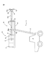
図1は掘削機トレーラー1をかなり単純化して示す概略側面図である。掘削機トレーラー1は、移動キャリア2とブーム(boom)3を含み、ブームの端に送りビーム(feed beam)4があり、そこに衝撃機構5と回転機構6を有する掘削機8が設置されている。図1の掘削機トレーラー1はさらに工具9を有し、その近位端は掘削機8に結合され、遠位端は穿孔される岩の方に向いている。工具9の近位端9’は図1において破線で概略的に示されている。図1の掘削にトレーラー1の工具9はドリルロッド10a,10b,及び10cと工具9の遠位端9”におけるドリルビット11を含む。ドリルビット11にはボタン11aが設けられているが、他のドリルビット構造も可能である。セクションドリルロッドによる穿孔は長孔穿孔とも呼ばれるが、明けようとする孔の深さに応じていくつかのドリルロッドがドリルビット11と掘削機8の間に取り付けられる。工具9はまたフィードビーム4に取り付けられたガイド支持部によっても支持される。
FIG. 1 is a schematic side view showing the
掘削機は上で説明したものと異なる構造を有してもよい。例えば、ダウンザホール(DTH)穿孔では、衝撃機構は掘削機においてドリルビットのすぐ近くにある穿孔の底部に位置し、ドリルビットはドリルロッドを介して孔の上にある回転機構に結びつけられる。 The excavator may have a different structure than that described above. For example, in down-the-hole (DTH) drilling, the impact mechanism is located at the bottom of the drilling in the excavator in the immediate vicinity of the drill bit, and the drill bit is connected via a drill rod to a rotating mechanism above the hole.
衝撃機構5には圧力媒質の作用の下で往復する打撃ピストンが設けられ、それが直接に、又は工具9と打撃ピストンの間にあるドリルシャンク又は別の種類のアダプタを介して工具を打撃する。もちろん、異なる構造の衝撃機構も可能である。衝撃機構5の動作も、機械的に往復する打撃ピストンなしで電磁気又は油圧を利用するものであってもよく、この文脈で衝撃機構という用語はそのような特性に基づく衝撃デバイスを指すこともある。衝撃機構5によって発生される応力波は、ドリルロッド10aから10cまでに沿って工具9の遠位端のドリルビット11の方に送られる。応力波がドリルビット11に達すると、ドリルビット11及びそのボタン11aが穿孔する岩石12を打撃して、穿孔する岩石12に強い応力を生じ、それによって岩石12にクラックが形成される。岩石12に加えられる又は作用する応力波の一部は、普通、工具9に反射され、工具9に沿って衝撃機構5の方へ反射される。
The
図2は応力波を示す概略図であり、穿孔される岩石12の方へ伝播する応力波は参照記号siで表され,岩石12から工具9へ反射される応力波は参照記号srで表されている。
FIG. 2 is a schematic diagram showing the stress wave, where the stress wave propagating toward the drilled
穿孔の間、回転機構6は工具9に連続的に回転力を伝達し、ドリルビット11のボタン11aの打撃後の位置を変えて次の打撃で岩石12の新たなスポットを打撃させる。図1の掘削機トレーラー1はまた送りビーム4に配置された送り機構7を含み、それに対して掘削機8が動くことができるように配置されている。穿孔の間、送り機構7は掘削機8を送りビーム4上で前方へ押し出し、それによりドリルビット11を岩石12に押しつけるように配置されている。
During drilling, the rotating mechanism 6 continuously transmits rotational force to the
図1は掘削機8の構造に対して現実にあるものよりかなり小さな掘削機トレーラー1を示している。分かりやすくするために、図1の掘削機トレーラー1は、ただひとつのブーム3,送りビーム4,掘削機8、及び送り機構7を有するだけであるが、掘削機トレーラーは送りビーム4,掘削機8、及び送り機構7を有するブーム3を複数備えることができることは明らかである。また、掘削機8は通常、ドリルビット11がブロックされないようにするために放水手段を含む。分かりやすくするために図1には放水手段は示されていない。掘削機は油圧で操作されるが、空気圧又は電気的に操作することもできる。
FIG. 1 shows an
図3は、例えば図1の掘削機トレーラーで用いることができる岩石破砕システム14を示す概略部分断面側面図である。図3の岩石破砕システム14は、衝撃機構5と衝撃機構5に結合された工具9を含む。図3の岩石破砕システム14の工具9はドリルロッド10a,10bとドリルロッド10bの遠位端のドリルビット11を含む。衝撃機構5はフレーム構造5’と工具9に向けて打撃パルスを供給するように配置された打撃デバイス15を含む。図3の実施形態では、打撃デバイス15は打撃ピストンという形を有するが、打撃デバイス15と衝撃機構5が実際に実現される仕方にはいろいろな形がある。図3の衝撃機構5はまた、ドリルシャンク16を含み、工具9の近位端9’がそれに固定され、打撃デバイス15は打撃を直接工具9に向けずにドリルシャンク16に向けるように配置されるのでドリルシャンク16が打撃デバイス15と工具9の間の中間部材になっている。図3の衝撃機構5はさらに減衰デバイス17を含み、これは図3にきわめて概略的に示されているが、ドリルシャンク16と打撃デバイス15の間に位置して衝撃機構5のフレーム構造5’に支持されている。減衰デバイス17の役割は、岩石12から工具9及び衝撃機構5へ反射して戻ってくる応力波の作用を減衰させることである。減衰デバイス17はまた、打撃デバイス15が供給する打撃がドリ・シャンク16に最適な効果を及ぼすようなポイントに打撃デバイスに対してドリルシャンク16を位置づける役割もする。減衰デバイス17が実際に実施される形は、例えば、圧力媒質で作動するひとつ以上のシリンダである。
FIG. 3 is a schematic partial cross-sectional side view showing a
図3の実施形態では、衝撃機構5と、衝撃機構5に結合された工具9が岩石破砕のさいに応力を受ける岩石破砕システム14を構成している。しかし、岩石破砕システムの実施にはいろいろな仕方がある。例えば破砕ハンマーでは、岩石破砕システムは普通、打撃デバイスと工具だけを含み、打撃デバイスが供給する打撃は工具9にストレートに伝わる。実施の仕方によって、岩石破砕システムは油圧、空気圧、又は電気的に作動する、又は岩石破砕システムの動作は油圧、空気圧、及び/又は電気的に作動するデバイスの組合せとして実施される。分かりやすくするために、図1と3には岩石破砕システムの動作のために必要な、当業者には公知である圧力媒質の配管も電気導線も示されていない。
In the embodiment of FIG. 3, the
図4は、図3の岩石破砕システム14においてひとつ以上の永久磁石18を配置できるいくつかの可能な場所を概略的に示している。分かりやすくするために、衝撃機構5のフレーム構造5’は図4では省略されている。永久磁石18は、永久磁化状態にされることができる要素である。永久磁石18が永久磁化状態にされると、それらは磁界を生じ、岩石破砕システム14の部材の少なくとも一部が少なくともひとつの永久磁石18の磁界の作用を受けると、岩石破砕システム14の部材の少なくとも一部がさらに永久磁化状態にされる。さらに、岩石破砕の間に永久磁化状態にされた部材に応力が作用すると、言い換えると、永久磁化状態にされた岩石破砕システムの部材に応力が作用すると、応力によってその部材の磁気的性質に変化が生ずる。
FIG. 4 schematically illustrates several possible locations where one or more
少なくとも一部が永久磁化状態にされる岩石破砕システム14の部材は、例えば、衝撃機構5,衝撃機構5のフレーム構造5’、打撃デバイス15,ドリルシャンク16,減衰デバイス17,岩石破砕システム14の工具9,すなわちドリルロッド10a,10b,10c及び/又はドリルビット11,などである。少なくとも一部が永久磁化状態にされる岩石破砕システム14の部材は、また、例えば衝撃機構におけるアダプタ又は結合スリーブであってもよい。永久磁化状態にされる岩石破砕システム14の部材は、このように岩石破砕のさいに出現する応力又は応力波を発生、伝播、又は減衰させる部材である。
The members of the
永久磁化状態とは、永久磁石のように比較的長い時間残っている磁化の状態、外部磁気源の断続的印加によって維持される磁化の状態、外部磁界への曝露から部材物質に生じて内部に残っている磁化の状態、又は測定期間中に外部磁気源によって維持される必要がない持続的な磁化の状態、である。永久磁化状態が能動的手段(そのいくつかの例をあとで示す)又は永久磁石などの非能動的手段による一回の断続的印加で得られること可能である。 Permanent magnetized state refers to the state of magnetization that remains for a relatively long time like a permanent magnet, the state of magnetization that is maintained by intermittent application of an external magnetic source, and is caused by exposure to an external magnetic field in a member material to the inside The state of magnetization that remains, or the state of persistent magnetization that does not need to be maintained by an external magnetic source during the measurement period. Permanent magnetization states can be obtained with a single intermittent application by active means (some examples of which will be given later) or non-active means such as permanent magnets.
部材の磁気的性質の変化とは、例えば、部材の磁界の変化、部材の磁界の磁束の変化、又は部材の磁化の状態又は強度の変化、などである。部材の磁気的性質の変化は、このように応力を受けている部材の物質の状態変化の結果である。本発明のソリューションは永久磁化の状態を扱うので、応力を受ける部材の磁気的性質の変化を高い一貫性で検出できる。 The change in the magnetic property of the member is, for example, a change in the magnetic field of the member, a change in the magnetic flux of the magnetic field of the member, or a change in the magnetization state or strength of the member. The change in the magnetic properties of the member is the result of a change in the state of the material of the member under stress in this way. Since the solution of the present invention deals with the state of permanent magnetization, changes in the magnetic properties of the stressed member can be detected with high consistency.
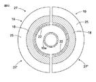
図4では、複数の永久磁石18が支持構造19に固定され、円形の形状を有するので、永久磁石18を部材を囲むように配置し、部材の少なくとも一部が少なくともひとつの永久磁石18によって永久磁化状態にされるようにすることができる。図4では、永久磁石18は、工具9のロッド10a、ドリルシャンク16,減衰デバイス17及び打撃デバイス15を囲むように配置されている。
In FIG. 4, a plurality of
図5は、図3の岩石破砕システム14においてひとつ以上の永久磁石18を配置できる別の可能な場所を概略図で示している。図5でも、永久磁石はやはり円形の形状を有するが、図4に示された支持構造はなくなっている。図5の実施形態では、衝撃機構5のフレーム構造5’、ドリルシャンク16、減衰デバイス17及び打撃デバイス15に空所20が形成されており、それにより部材の空所20に永久磁石18を配置することによって前記部材の内側に永久磁石を配置できる。例えば、ドリルロッド10aの内側もある種の空所を形成しており、少なくともひとつの永久磁石18をそこに配置できる。ドリルシャンク16では、永久磁石18を、例えば放水(flushing)チャンネル31に配置できる。ドリルシャンク16において放水チャンネルがある種の空所を形成している。
FIG. 5 schematically illustrates another possible location where one or more
図4と5は、岩石破砕システム14で永久磁石18を配置できるいくつかの可能な場所を概略的に示している。しかし、装置はひとつの岩石破砕システム部材の少なくとも一部を永久磁化状態に配置するための永久磁石をただひとつ含む。あるいはまた、装置はひとつ以上の岩石破砕システム部材の少なくとも一部を永久磁化状態に配置するための永久磁石を2つ以上含む。したがって、装置には、各々がひとつの関連永久磁石18を有するいくつかの岩石破砕システム部材があるか又はいくつかの関連永久磁石18を有するひとつ以上の岩石破砕システム部材がある。後者の実施形態の例も図4と5に概略的に示されており、図4はドリルシャンク16を囲む2つの続いた永久磁石18を示し、図5は衝撃機構5のフレーム構造5’の空所20に配置された2つの続いた永久磁石18を示している。装置でひとつの岩石破砕システム部材に関連する永久磁石がいくつかある場合、それらの永久磁石は特定の岩石破砕システム部材の周方向で互いに続くように配置することもできる。この場合、複数の永久磁石が、例えば長方形の形を有することができる。
4 and 5 schematically illustrate some possible locations where the
図4と5の例では、永久磁石は岩石破砕システム部材の近くに恒久的に配置されるので、図4と5の例では永久磁石は岩石破砕システムの部材の少なくとも一部を連続的に永久磁化状態にする。 In the examples of FIGS. 4 and 5, the permanent magnets are permanently located near the rock crushing system members, so in the examples of FIGS. 4 and 5, the permanent magnets permanently suspend at least some of the members of the rock crushing system. Set to magnetized state.
図4と5はまた、岩石破砕動力の少なくともひとつのパラメータを岩石破砕システム部材の磁気的性質の変化に基づいて測定する手段を概略図で示している。部材の磁気的性質の変化は、岩石破砕システム14の動作の間に岩石破砕システム14の部材に作用する応力波などの応力によって生ずる。
FIGS. 4 and 5 also schematically show means for measuring at least one parameter of rock crushing power based on changes in the magnetic properties of the rock crushing system members. Changes in the magnetic properties of the members are caused by stresses such as stress waves acting on the members of the
図4において、岩石破砕システムの部材の磁気的性質の変化に基づいて岩石破砕動力の少なくともひとつのパラメータを測定する手段は測定コイル21であり、図4の実施形態では、ドリルロッド10aの近くの永久磁石18によって永久磁化状態に配置されるドリルロッド10aの領域にドリルロッド10aを囲むように配置される。しかし、これに代えて、測定コイル21は他の岩石破砕システム部材の近くで永久磁石18によって永久磁化状態にされる部材の領域に配置してもよい。また、2つ以上の測定コイル21が特定のひとつ以上の部材の磁気的性質の変化を測定するために同じ又は異なる岩石破砕システム部材の近くにあってもよい。部材の磁気的性質の変化により、部材の磁気的性質の変化と等価な電圧又は電流が測定コイルに誘導される。誘導される電圧又は電流は、逆に、特定岩石破砕システム部材に作用する応力を表す。
In FIG. 4, the means for measuring at least one parameter of the rock breaking power based on the change in the magnetic properties of the members of the rock breaking system is the measuring
図5において、部材の磁気的性質の変化を測定するための測定部材は磁気センサ22であり、図5の実施形態で、これはドリルシャンク16に、ドリルシャンク16において永久磁石18によって永久磁化状態に配置されるドリルシャンクの領域に配置される。しかし、これに代えて、磁気センサ22は他の岩石破砕システム部材に、永久磁化状態に配置される部材の領域に配置してもよい。また、2つ以上の磁気センサ22を、特定のひとつ以上の部材の磁気的性質の変化に基づいて岩石破砕動力の少なくともひとつのパラメータを測定するために同じ又は異なる岩石破砕システム部材に配置してもよい。磁気センサ22は、例えば、コイル、磁力計、磁気抵抗素子、又はホールセンサである。
In FIG. 5, the measuring member for measuring the change in the magnetic properties of the member is a
測定部材によって得られた測定情報は、矢印23で概略的に示された有線結合又は無線結合によって、データ処理ユニット24に送られる。データ処理ユニット24は測定部材によって得られた測定情報を処理又は修飾して測定部材によって得られた測定情報の意味がある表現に到達するためのソフトウエア及び/又はハードウエア手段を含み、測定情報を分析及び/又は利用して岩石破砕システム14又は掘削機トレーラー1全体又は岩石破砕ハンマーの動作を制御できるようにする。例えば、特許文献3及び4で開示されている処理又は修飾方法を適用することができる。
The measurement information obtained by the measuring member is sent to the
永久磁石18が岩石破砕システムの部材の少なくとも一部を永久磁化状態にするために用いられるとき、岩石破砕システム部材に作用する応力のために岩石破砕システム部材の磁気的性質の変化の測定に乱れは生じないが、従来技術のソリューションは岩石破砕システム部材の磁気的性質の変化を測定すると同時に岩石破砕システム部材を磁化する磁化コイルを含むため、この乱れが発生する。
When the
岩石破砕動力を測定する装置の動作を考えると、永久磁石など測定動作に関連する計器は、非導電性材料から製造されることが好ましい。しかし、コイルがあるとすれば、それは当然ながら導電性材料で作られる。 Considering the operation of the device for measuring rock crushing power, it is preferred that the instrument associated with the measuring operation, such as a permanent magnet, is manufactured from a non-conductive material. However, if there is a coil, it is of course made of a conductive material.
図6は、岩石破砕システム部材の少なくとも一部を永久磁化状態にすることを意図した磁化手段構造27を示す概略一部断面側面図であり、図7は、図6の磁化手段構造27の概略一部断面端面図を示す。磁化手段構造27は、単一の永久磁石18を含み、図6と7の実施形態ではそれはリング形状を有し、岩石破砕システム部材、すなわち図6と7の例では、ドリルロッド10aを囲むように配置される。永久磁石18は、永久磁石18を囲むジャケット25と端板26を含む支持構造19の内側に挿入されるので、支持構造19は閉じた構造となって永久磁石18を支持構造19の内側に囲い込む。分かりやすくするために、ジャケット25の断面を表す線は図7には示されない。端板26の少なくともひとつは永久磁石18を支持構造19の内側に挿入するために取り外すことができる。支持構造19は永久磁石18からの磁界を岩石破砕システム部材へ導くガイド部材を構成して岩石破砕システム部材の少なくとも一部を永久磁石18から供給される磁界によって永久磁化状態に配置する。
FIG. 6 is a schematic partial cross-sectional side view showing a magnetization means
図6と7の実施形態では、リング状の永久磁石18は、岩石破砕システム部材すなわちドリルロッド10aを完全に囲むように配置される。問題の岩石破砕システム部材を部分的に又は完全に囲む永久磁石18は別の曲線形状であってもよい。問題の岩石破砕システム部材を少なくとも部分的に囲む永久磁石18の形状又は形態は、曲線又は円環形状以外の別種の少なくとも部分的に囲繞する形状であってもよい。
In the embodiment of FIGS. 6 and 7, the ring-shaped
図6と7の実施形態では、また、測定センサ22が永久磁石18の内縁の内側に配置される。このように、図6と7の実施形態は永久磁石18、すなわち少なくともその一部が永久磁化状態に配置される要素、と測定部材、すなわち測定センサ22、との組合せを与える。測定センサ22の端(図示せず)は、例えば、測定センサ22がコイルの形である場合、端板26を通って延びるように配置される。
In the embodiment of FIGS. 6 and 7, the
図8は第2の磁化手段構造27を示す概略部分断面端面図である。分かりやすくするために、ジャケット25の断面を表す線は図8には示されていない。図8では、図7と比較すると、図6のリング状の永久磁石18が丸棒の形のいくつかの永久磁石に置き換えられ、それらが支持構造19のジャケット25で互いに隣接して配置され、永久磁石18が問題の岩石破砕システム部材、すなわちドリルロッド10a,の全周を囲む形になっている。
FIG. 8 is a schematic partial cross-sectional end view showing the second magnetizing means
図9は、第3の磁化手段構造27を示す概略部分断面端面図である。分かりやすくするために、ジャケット25の断面を表す線は図9には示されていない。図9では、図8と比較すると、丸棒の形のリング状永久磁石18が支持構造19のジャケット25で互いに隣接して配置され、永久磁石18が問題の岩石破砕システム部材、すなわちドリルロッド10a,の周の一部だけを囲むようになっている。
FIG. 9 is a schematic partial sectional end view showing the third magnetization means
図6から9までの実施形態では、いくつかの永久磁石、すなわちひとつ以上の永久磁石があって、岩石破砕システム部材の少なくとも一部を永久磁化状態にするように岩石破砕システムの部材を少なくとも部分的に囲むように配置されている。図8と9の実施形態において、棒状の永久磁石の断面形状は丸い形と異なるものであってもよい。 In the embodiment of FIGS. 6 to 9, there are several permanent magnets, ie one or more permanent magnets, at least part of the members of the rock breaking system such that at least part of the rock breaking system member is in a permanent magnetized state. It is arranged so that it surrounds. 8 and 9, the cross-sectional shape of the rod-shaped permanent magnet may be different from the round shape.
図10は、第4の磁化手段構造27を示す概略部分断面端面図である。分かりやすくするために、ジャケット25の断面を表す線は図10には示されていない。図10の磁化手段構造27は2つの部分27’、27”を有し、各々支持構造19を含み、永久磁石18と測定センサ22は半円弧の形を有する。2つの部分27’、27”は、例えばジョイントヒンジを用いて互いに組み合せ、部分を互いに対置させることによって丸い形を有するひとつの磁化手段構造27を形成することができる。測定センサ22も互いに結合させることができる。分かりやすくするために、図10の部分27’、27”は、その間に小さな距離を有するように示され、ジョイントヒンジは図10には示されていない。図10の磁化手段構造27は岩石破砕システム部材のまわりに、部材の端の方からだけでなく部材の側面の方からも組み立てることができる。
FIG. 10 is a schematic partial cross-sectional end view showing the fourth magnetizing means
図10の実施形態では、2つの永久磁石から成るグループを合わせて配置して周縁構造を形成し、それを開いて永久磁石のグループを岩石破砕システム部材のまわりに配置することができる。図10の実施形態では、2つの永久磁石が実際には単一の永久磁石を構成して岩石破砕システム部材の周りに配置される。また、この周縁構造とは異なる形状又は形態の永久磁石を何らかの仕方で開放可能に配置することもできる。また、測定部材も、図10に関して上で説明したと同様の仕方で開放可能に配置することができる。磁化手段及び/又は測定部材の構造が開放可能であるとき、岩石破砕システムの付近にそれを設置して、又は岩石破砕システムを少なくとも部分的に囲むような仕方で開くようにすることができる。また、それは磁石、磁化手段、岩石破砕システム、又は掘削機トレーラーなどの岩石破砕デバイス、の保守及び点検のために開くこともできる。 In the embodiment of FIG. 10, a group of two permanent magnets can be placed together to form a peripheral structure that can be opened to place a group of permanent magnets around a rock crushing system member. In the embodiment of FIG. 10, two permanent magnets actually constitute a single permanent magnet and are placed around a rock crushing system member. Further, a permanent magnet having a shape or a shape different from that of the peripheral structure can be arranged to be openable in some way. Also, the measurement member can be releasably arranged in a manner similar to that described above with respect to FIG. When the structure of the magnetizing means and / or the measuring member is openable, it can be placed in the vicinity of the rock breaking system or be opened in a way that at least partially surrounds the rock breaking system. It can also be opened for maintenance and inspection of magnets, magnetizing means, rock crushing systems, or rock crushing devices such as excavator trailers.
図6から10までの実施形態では、単数又は複数の永久磁石18は導電性材料から製造することができ、ジャケット25が非導電性材料で作られていれば、岩石破砕動力の測定に何も劣化的な有害な影響を及ぼさない。
In the embodiment of FIGS. 6 to 10, the permanent magnet or
図6から10までの例では、磁化手段構造27は対象の磁気的性質の変化を測定する測定計器を提供又は構成し、この測定計器は、対象の少なくとも一部を永久磁化状態にする少なくともひとつの磁化手段と、対象に作用する応力に応答した対象の磁気的性質の変化を記述する少なくともひとつのパラメータを測定するための少なくともひとつの測定部材を含む。図6から10までの例では、この対象はドリルロッド10aである。このように、測定計器は、対象の少なくとも一部を永久磁化状態に配置するための少なくともひとつの磁化手段と、対象に加えられる応力に応答した対象の磁気的性質の変化を記述する少なくともひとつのパラメータを測定するための少なくともひとつの測定部材の両方を含む。磁化手段は、例えば、上述したような永久磁石18,又は磁化コイル28,又はあとで説明するようなひとつ以上の永久磁石18と磁化コイル28の組合せなどである。測定部材は、例えば、上述したような測定コイル21又は磁気センサ22である。測定計器の構造は、例えば図10の例に関する記述で上に開示したように開放可能である。本明細書の例では、測定計器は岩石破砕システム14の部材の磁気的性質の変化を測定するために用いられるが、一般的には、開示された測定計器は応力を受ける他の対象の磁気的性質の変化を測定するためにも用いられる。
In the examples of FIGS. 6 to 10, the magnetizing means
上述の例では、岩石破砕動力を測定する装置で、少なくともその一部が永久磁化状態にされる要素はこのように永久磁石であり、この永久磁石の磁界がさらに岩石破砕システムの部材の少なくとも一部を永久磁化状態にする。あるいはまた、岩石破砕動力を測定する装置において、少なくともその一部が永久磁化状態にされる要素はまた、岩石破砕システムの部材であってもよい、すなわち、例えば図11を参照すると、衝撃機構5,打撃デバイス15,ドリルシャンク16,減衰デバイス17,岩石破砕システム14の工具9,例えばドリルロッド10a,10b、10c、及び/又はドリルビット11,そして図11には示されていない衝撃機構5のフレーム構造5’など、であってもよい。岩石破砕システムの部材の少なくとも一部が永久磁化状態にされるとき、部材自身が永久磁化状態にされ、それにより部材自身も磁気的性質を有し、その変化が測定されて、部材の磁気的性質の変化に基づいて岩石破砕動力の少なくともひとつのパラメータが測定される。
In the above example, in the device for measuring the rock crushing power, the element whose at least part is made in the permanent magnetized state is thus a permanent magnet, and the magnetic field of this permanent magnet is further added to at least one member of the rock crushing system. The part is in a permanent magnetized state. Alternatively, in the device for measuring rock crushing power, the element, at least part of which is in a permanent magnetized state, may also be a member of a rock crushing system, i.e. referring to FIG. ,
図11は磁化手段として用いられる磁化コイル28を示しており、これは岩石破砕システム14の部材の少なくとも一部を永久磁化状態にするために用いられる。図11の例では、ひとつ以上の磁化コイル28がドリルロッド10a、ドリルシャンク16,減衰デバイス17,及び打撃デバイス15を囲むように配置されている。ひとつ以上の磁化コイル28は、また、打撃デバイス5のフレーム構造を囲むように配置できる。図11では、ドリルロッド10a、減衰デバイス17,及び打撃デバイス5がただひとつの磁化コイル28によって囲まれているが、2つ以上の磁化コイル28によって囲まれるようにすることもできる。磁化コイル28は、また、岩石破砕システム部材に設けられた空所に、図5の例における永久磁石と同様の仕方で挿入することもできる。岩石破砕システム14の部材の磁気的性質の変化は、例えば図4と5の例で説明したように測定される。
FIG. 11 shows a magnetizing
図11の装置はまた、電源29を含み、これは矢印30で示される結合によって磁化コイルに必要な電力を供給するように構成される。電源29は、岩石破砕システム14の部材の少なくとも一部を永久磁化状態にするための電磁パルスを供給するように構成される。電磁パルスの長さ、形、及び振幅は固定されていても、可変であってもよい。岩石破砕システム14の部材は、岩石破砕システムの動作状態に基づいて、測定部材の動作に基づいて、又は岩石破砕システム14の部材の磁気的性質の変化に基づいて、間隔をおいて、例えば規則的間隔で、永久磁化状態にされる。岩石破砕システム14の部材の少なくとも一部が岩石破砕システム14の部材を使用する前に永久磁化状態にされることもある。
The apparatus of FIG. 11 also includes a
岩石破砕システム14の部材が間隔をおいて永久磁化状態にされる場合、いくつかのタイム期間に磁化の作業が行われる。このタイム期間は、絶対時刻、岩石破砕時刻、ワークシフト期間、などと関連する。間隔(インターバル)はまた、岩石破砕作業、例えば穿孔距離、工具9から受ける打撃回数、打撃エネルギー、又は工具9を伝わるエネルギー一般、などにも基づいて定められる。間隔(インターバル)はまた、少なくともそのインターバル内に磁化作業が行われるようにするために用いられる。すなわち、ある定められたインターバル内で磁化作業が行われていない場合、磁化の作業が実行される。
When the members of the
岩石破砕システムの部材が岩石破砕システム14の動作状態に基づいて永久磁化状態にされる場合、磁化の作業は、例えば、打撃デバイス15が休んでいる状態の間に、例えば引き続く打撃の間、打撃シリーズの間、孔を穿ち始めたとき、新しいドリルロッド10aへの交換の間、穿孔が完了したとき、穿孔のために岩石破砕システムを位置決めしているとき、岩石破砕システム又はデバイス、例えば掘削機トレーラー1を岩石破砕現場で、移動する間、に実行することができる。
When the rock crushing system members are made permanently magnetized based on the operating state of the
岩石破砕システム14の部材が測定部材の動作に基づいて永久磁化状態にされる場合、磁化作業は測定部材が休んでいる状態にある間、又は、例えば測定の質が磁化の状態が不適切なために低下していると認められた時、に実行される。磁化の作業はまた、測定された値又は測定結果に基づいて実行されてもよい。測定された値又は測定結果は別のセンサ、多分岩石破砕システム又は測定システムの外部にあるセンサ、から得られる。
When the member of the
岩石破砕システム14の部材が岩石破砕システムの部材の磁気的性質の変化に基づいて永久磁化状態にされる場合、磁化作業は信頼できる測定情報が得られなくなるほど永久磁化状態が変化したと認められた時に実行される。
When a member of the
岩石破砕システム14の部材がその岩石破砕システム14においてその部材が使用される前に永久磁化状態にされる場合、その部材の少なくとも一部が、例えば、その部材の製造の後で、工場又は岩石破砕システムの使用現場でその部材を岩石破砕システムに組み立てる前に、又はその部材を岩石破砕システムに組み立てた後でしかしその岩石破砕システムの実際の作動の前に、永久磁化状態にされる。したがって、その岩石破砕システムの部材の少なくとも一部が岩石破砕システムの外部の磁界によって永久磁化状態にされる。
If a member of the
磁化の作業は、例えばデータ処理ユニット24によって制御される。
The magnetization operation is controlled by the
上の図11の例とそれに関連した説明では、岩石破砕システムの部材は磁化手段として磁化コイル28だけを用いて永久磁化状態にされる。しかし、永久磁石と磁化コイル28を組み合わせてすることも可能である。また、磁化コイル28を用いる代わりに、永久磁石だけを用いて岩石破砕システムの特定部材を永久磁化状態にするために、上で説明したように特定の時間期間だけ永久磁石を特定の岩石破砕システム部材の近くに配置することも可能である。また、永久磁石だけを用いて岩石破砕システムの部材の少なくとも一部を断続的に永久磁化状態にすることも可能である。
In the example of FIG. 11 above and the description associated therewith, the members of the rock crushing system are made permanently magnetized using only the magnetizing
岩石破砕システムの部材の少なくとも一部が永久磁化状態にされ、必要ならばその永久磁化状態が刺激される場合、岩石破砕システムの部材自身が、部材の磁気的性質の変化に基づいて岩石破砕動力のパラメータを測定するときに観測される磁気的性質を与える。この場合、岩石破砕システム部材に作用する応力による岩石破砕システム部材の磁気的性質の変化の測定に乱れは生じない。従来技術のソリューションでは、岩石破砕システム部材の磁気的性質の変化の測定の間に同時に岩石破砕システム部材を磁化するために磁化コイルを用いるので、この乱れが発生する。 When at least a part of a rock crushing system member is brought into a permanent magnetized state and, if necessary, the permanent magnetized state is stimulated, the rock crushing system member itself is driven by a rock crushing power based on changes in the magnetic properties of the member. Gives the magnetic properties observed when measuring the parameters. In this case, there is no disturbance in the measurement of the change in the magnetic properties of the rock crushing system member due to the stress acting on the rock crushing system member. This disturbance occurs because prior art solutions use a magnetizing coil to simultaneously magnetize the rock breaking system member during the measurement of the change in magnetic properties of the rock breaking system member.
ある実施形態では、磁化コイル28が測定コイルとしても用いられる。この実施形態では、磁化コイル28は、岩石破砕システムの部材を永久磁化状態に配置するための電磁パルスを供給するためにも、部材が永久磁化状態に配置された後、すなわち磁化コイルが岩石破砕システムの部材を永久磁化状態に配置するために用いられていないときに部材の磁気的性質の変化に基づいて岩石破砕動力のパラメータの測定を行うためにも用いられる。
In some embodiments, the magnetizing
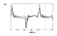
図12と13は応力波の測定結果の例を概略図で示しており、図13は図12の測定の最初の部分をさらに詳しく示している。図12と13で、破線は岩石破砕システム部材に取り付けられた歪みゲージによって測定された応力波を表す。連続した線は、こちらは永久磁石を用いて同じ岩石破砕システム部材を永久磁化状態にしたとき、測定コイルによって測定された同じ応力波を表している。図12と13から、本発明のソリューションによって得られる応力波測定は歪みゲージによって得られる測定に対応することが見られる。歪みゲージによる測定は、歪みゲージが岩石破砕システム部材に直接固定されるので、岩石破砕システム部材に現れる応力波に正確に追従していると考えられる。 12 and 13 schematically show examples of stress wave measurement results, and FIG. 13 shows the first part of the measurement of FIG. 12 in more detail. In FIGS. 12 and 13, the dashed line represents the stress wave measured by a strain gauge attached to the rock crushing system member. The continuous line represents the same stress wave measured by the measuring coil when the same rock crushing system member is brought into a permanent magnetized state using a permanent magnet. From FIGS. 12 and 13, it can be seen that the stress wave measurement obtained by the solution of the present invention corresponds to the measurement obtained by the strain gauge. In the measurement by the strain gauge, it is considered that the strain gauge is directly fixed to the rock crushing system member, so that it accurately follows the stress wave appearing in the rock crushing system member.
上で開示された測定装置の例は岩石破砕のさいに岩石破砕システムに作用する応力波の測定に関するものであるが、この測定装置はまた別の仕方で岩石破砕動力又は関連パラメータの測定に利用できる。この測定装置はまた、他の現象又は事象の決定、例えば打撃頻度又は破砕された岩石の特性の決定、並びに岩石破砕システム又はその部材の状態監視、にも利用できる。 The example of the measuring device disclosed above relates to the measurement of stress waves acting on the rock breaking system during rock breaking, but this measuring device can also be used in other ways to measure rock breaking power or related parameters. it can. This measuring device can also be used to determine other phenomena or events, such as determining the frequency of hits or the properties of the crushed rock, as well as monitoring the condition of the rock crushing system or its components.
技術の進歩に伴って本発明のコンセプトはいろいろな仕方で実施できるようになるということは当業者には明らかであろう。本発明及びその実施形態は、上で説明した例に限定されるものではなく、特許請求の範囲内でいろいろと変更できるものである。 It will be apparent to those skilled in the art that as technology advances, the inventive concept can be implemented in a variety of ways. The invention and its embodiments are not limited to the examples described above, but may be varied in many ways within the scope of the claims.
5 衝撃機構(部材、要素)
5’ フレーム構造(部材、要素)
9 工具(部材、要素)
10a,10b,10c ドリルロッド(部材、要素)
11 ドリルビッド
14 岩石破砕システム
15 打撃デバイス(部材、要素)
16 ドリルシャンク(部材、要素)
17 減衰デバイス(部材、要素)
18 永久磁石(磁化手段、要素)
20 空所
21,22 測定部材
28 磁化手段
5 Impact mechanism (members, elements)
5 'frame structure (members, elements)
9 Tools (members, elements)
10a, 10b, 10c Drill rod (member, element)
11
16 Drill shank (member, element)
17 Attenuation device (member, element)
18 Permanent magnet (magnetization means, element)
20
Claims (14)
岩石破砕の間に応力を受ける岩石破砕システム(14)の少なくともひとつの部材(5,5’,9,10a,10b,10c,15,16,17)と、
前記部材の磁気的性質の変化に基づいて岩石破砕動力の少なくともひとつのパラメータを測定するための少なくともひとつの測定部材(21,22)と、
を含む装置において、
少なくともひとつの要素(5,5’,9,10a,10b,10c,15,16,17,18)であって、該要素の少なくとも一部が、測定期間中に外部磁気源によって維持する必要がない永久磁化状態にあることを特徴とする装置。 An apparatus for measuring rock crushing power,
At least one member (5,5 ', 9,10a, 10b, 10c, 15,16,17) of the rock crushing system (14) that is stressed during rock crushing;
At least one measuring member (21, 22) for measuring at least one parameter of rock breaking power based on a change in magnetic properties of the member;
In an apparatus including:
At least one element (5,5 ', 9,10a, 10b, 10c, 15,16,17,18), at least part of which needs to be maintained by an external magnetic source during the measurement period Device characterized in that there is no permanent magnetized state.
岩石破砕システム(14)の部材(5,5’,9,10a,10b,10c,15,16,17)に岩石破砕中の応力を作用させるステップと、
前記部材の磁気的性質の変化に基づいて岩石破砕動力の少なくともひとつのパラメータを測定するステップと、
を含む方法において、
岩石破砕システム(14)の部材(5,5’,9,10a,10b,10c,15,16,17)の少なくとも一部を、測定期間中に外部磁気源によって維持する必要がない永久磁化状態にし、
その少なくとも一部が永久磁化状態にされた前記部材の磁気的性質の変化に基づいて岩石破砕動力の少なくともひとつのパラメータを測定する、
ことを特徴とする方法。 A method of measuring rock crushing power,
Applying the stress during rock crushing to the members (5, 5 ', 9, 10a, 10b, 10c, 15, 16, 17) of the rock crushing system (14);
Measuring at least one parameter of rock breaking power based on a change in magnetic properties of the member;
In a method comprising:
Permanent magnetization state in which at least part of the members (5, 5 ', 9, 10a, 10b, 10c, 15, 16, 17) of the rock crushing system (14) need not be maintained by an external magnetic source during the measurement period West,
Measuring at least one parameter of rock crushing power based on a change in magnetic properties of the member, at least a part of which is in a permanent magnetized state;
A method characterized by that.
Applications Claiming Priority (2)
| Application Number | Priority Date | Filing Date | Title |
|---|---|---|---|
| EP13171043.6A EP2811110B1 (en) | 2013-06-07 | 2013-06-07 | Arrangement and Method in Rock Breaking |
| EP13171043.6 | 2013-06-07 |
Publications (2)
| Publication Number | Publication Date |
|---|---|
| JP2014237217A JP2014237217A (en) | 2014-12-18 |
| JP5767368B2 true JP5767368B2 (en) | 2015-08-19 |
Family
ID=48578853
Family Applications (1)
| Application Number | Title | Priority Date | Filing Date |
|---|---|---|---|
| JP2014117892A Active JP5767368B2 (en) | 2013-06-07 | 2014-06-06 | Rock crushing apparatus and method |
Country Status (4)
| Country | Link |
|---|---|
| EP (1) | EP2811110B1 (en) |
| JP (1) | JP5767368B2 (en) |
| CN (1) | CN104236762A (en) |
| AU (1) | AU2014202974B2 (en) |
Families Citing this family (7)
| Publication number | Priority date | Publication date | Assignee | Title |
|---|---|---|---|---|
| SE540205C2 (en) * | 2016-06-17 | 2018-05-02 | Epiroc Rock Drills Ab | System and method for assessing the efficiency of a drilling process |
| EP3266975B1 (en) | 2016-07-07 | 2019-01-30 | Sandvik Mining and Construction Oy | Component for rock breaking system |
| CN109113742B (en) * | 2018-08-02 | 2019-12-31 | 中国矿业大学 | Coal reservoir stratum present ground stress prediction method |
| CN112403563A (en) * | 2020-10-30 | 2021-02-26 | 重庆贻晨兴工业设计有限责任公司 | Double-channel jaw crusher and using method thereof |
| CN116547435A (en) | 2020-12-21 | 2023-08-04 | 安百拓凿岩有限公司 | Method and system for optimizing drilling parameters during an ongoing drilling process |
| AU2021408910A1 (en) | 2020-12-21 | 2023-06-22 | Epiroc Rock Drills Aktiebolag | Method and system for detecting a state of a joint of a drill string |
| EP4276438A1 (en) * | 2022-05-13 | 2023-11-15 | Sandvik Mining and Construction Oy | Measuring rock breaking dynamics |
Family Cites Families (8)
| Publication number | Priority date | Publication date | Assignee | Title |
|---|---|---|---|---|
| FI69680C (en) | 1984-06-12 | 1986-03-10 | Tampella Oy Ab | FOERFARANDE FOER OPTIMERING AV BERGBORRNING |
| JPS6190037A (en) * | 1984-10-09 | 1986-05-08 | Takenaka Komuten Co Ltd | Method and device for measuring compressive strength of concrete |
| JPH01193180A (en) * | 1988-01-26 | 1989-08-03 | Mazda Motor Corp | Over-load detection method for striking tool |
| JPH055603A (en) * | 1991-06-27 | 1993-01-14 | Mazda Motor Corp | Stroke detector of piston |
| JP4217321B2 (en) * | 1997-12-26 | 2009-01-28 | ヤマハ発動機株式会社 | Load detection device |
| DE19932838A1 (en) | 1999-07-14 | 2001-01-18 | Hilti Ag | Method and device for determining the time course of the shock wave in a shock-stressed ferromagnetic component |
| DE10219950C1 (en) * | 2002-05-03 | 2003-10-30 | Hilti Ag | Pneumatic hammer mechanism with magnetic field sensitive sensor |
| FI122300B (en) * | 2008-09-30 | 2011-11-30 | Sandvik Mining & Constr Oy | Method and arrangement for a rock drilling machine |
-
2013
- 2013-06-07 EP EP13171043.6A patent/EP2811110B1/en active Active
-
2014
- 2014-06-02 AU AU2014202974A patent/AU2014202974B2/en active Active
- 2014-06-06 CN CN201410250032.7A patent/CN104236762A/en active Pending
- 2014-06-06 JP JP2014117892A patent/JP5767368B2/en active Active
Also Published As
| Publication number | Publication date |
|---|---|
| JP2014237217A (en) | 2014-12-18 |
| AU2014202974B2 (en) | 2016-06-23 |
| EP2811110B1 (en) | 2017-09-20 |
| AU2014202974A1 (en) | 2015-01-15 |
| EP2811110A1 (en) | 2014-12-10 |
| CN104236762A (en) | 2014-12-24 |
Similar Documents
| Publication | Publication Date | Title |
|---|---|---|
| JP5767368B2 (en) | Rock crushing apparatus and method | |
| JP4838324B2 (en) | Measuring device, rock breaking device, and stress wave measuring method | |
| FI122300B (en) | Method and arrangement for a rock drilling machine | |
| CN109312617B (en) | System and method for evaluating efficiency of a drilling process | |
| US11085286B2 (en) | Rock breaking device | |
| KR101900605B1 (en) | Component for rock breaking system | |
| AU2007302838B2 (en) | Percussion device and rock drilling machine | |
| Harkness et al. | Architectures for ultrasonic planetary sample retrieval tools | |
| WO2023218013A1 (en) | Measuring rock breaking dynamics | |
| EP3775484B1 (en) | A percussion device and a method for controlling a percussion mechanism of a percussion device | |
| RU2473766C2 (en) | Method to drill rocks and device for its realisation | |
| JP2009185511A (en) | Excavator and method of searching front of facing | |
| CA2851922A1 (en) | Arrangement and method in rock breaking | |
| CN212008430U (en) | Roadway looseness range testing device based on acoustic image method | |
| EP1791681B1 (en) | Method for breaking rock | |
| KR20200026701A (en) | Rock drilling device | |
| KR101638158B1 (en) | Device for prediction underground dynamic behavior of mines by using acoustic emission sensor | |
| CN110568079A (en) | Roadway looseness range testing device based on acoustic image method | |
| KR20080041170A (en) | Hollowness type rock drilling apparatus | |
| US20120098675A1 (en) | Verfahren zum lokalisieren eines bohrgeräts einer erdbohrvorrichtung method for localizing a boring device of an earth boring apparatus | |
| KR101476546B1 (en) | Hydraulic Hitting and Drilling Apparatus | |
| JP2022528399A (en) | How to control the excavation process of a striking excavator | |
| CN110426732A (en) | A kind of seismic source apparatus and its control method of sound wave gaging hole | |
| RU2560000C2 (en) | Device for drilling of rocks | |
| JP2013213398A (en) | Excavator and forward investigation method for cutting face |
Legal Events
| Date | Code | Title | Description |
|---|---|---|---|
| A131 | Notification of reasons for refusal |
Free format text: JAPANESE INTERMEDIATE CODE: A131 Effective date: 20150106 |
|
| TRDD | Decision of grant or rejection written | ||
| A01 | Written decision to grant a patent or to grant a registration (utility model) |
Free format text: JAPANESE INTERMEDIATE CODE: A01 Effective date: 20150519 |
|
| A61 | First payment of annual fees (during grant procedure) |
Free format text: JAPANESE INTERMEDIATE CODE: A61 Effective date: 20150618 |
|
| R150 | Certificate of patent or registration of utility model |
Ref document number: 5767368 Country of ref document: JP Free format text: JAPANESE INTERMEDIATE CODE: R150 |
|
| R250 | Receipt of annual fees |
Free format text: JAPANESE INTERMEDIATE CODE: R250 |
|
| R250 | Receipt of annual fees |
Free format text: JAPANESE INTERMEDIATE CODE: R250 |
|
| R250 | Receipt of annual fees |
Free format text: JAPANESE INTERMEDIATE CODE: R250 |
|
| R250 | Receipt of annual fees |
Free format text: JAPANESE INTERMEDIATE CODE: R250 |
|
| R250 | Receipt of annual fees |
Free format text: JAPANESE INTERMEDIATE CODE: R250 |
|
| R250 | Receipt of annual fees |
Free format text: JAPANESE INTERMEDIATE CODE: R250 |