JP5765663B2 - Interior material mounting structure - Google Patents
Interior material mounting structure Download PDFInfo
- Publication number
- JP5765663B2 JP5765663B2 JP2010290826A JP2010290826A JP5765663B2 JP 5765663 B2 JP5765663 B2 JP 5765663B2 JP 2010290826 A JP2010290826 A JP 2010290826A JP 2010290826 A JP2010290826 A JP 2010290826A JP 5765663 B2 JP5765663 B2 JP 5765663B2
- Authority
- JP
- Japan
- Prior art keywords
- interior material
- front pillar
- vehicle body
- body panel
- protruding piece
- Prior art date
- Legal status (The legal status is an assumption and is not a legal conclusion. Google has not performed a legal analysis and makes no representation as to the accuracy of the status listed.)
- Active
Links
Images


Classifications
-
- B—PERFORMING OPERATIONS; TRANSPORTING
- B60—VEHICLES IN GENERAL
- B60R—VEHICLES, VEHICLE FITTINGS, OR VEHICLE PARTS, NOT OTHERWISE PROVIDED FOR
- B60R13/00—Elements for body-finishing, identifying, or decorating; Arrangements or adaptations for advertising purposes
- B60R13/02—Internal Trim mouldings ; Internal Ledges; Wall liners for passenger compartments; Roof liners
- B60R13/0206—Arrangements of fasteners and clips specially adapted for attaching inner vehicle liners or mouldings
-
- B—PERFORMING OPERATIONS; TRANSPORTING
- B60—VEHICLES IN GENERAL
- B60R—VEHICLES, VEHICLE FITTINGS, OR VEHICLE PARTS, NOT OTHERWISE PROVIDED FOR
- B60R13/00—Elements for body-finishing, identifying, or decorating; Arrangements or adaptations for advertising purposes
- B60R13/02—Internal Trim mouldings ; Internal Ledges; Wall liners for passenger compartments; Roof liners
- B60R13/0212—Roof or head liners
-
- B—PERFORMING OPERATIONS; TRANSPORTING
- B60—VEHICLES IN GENERAL
- B60R—VEHICLES, VEHICLE FITTINGS, OR VEHICLE PARTS, NOT OTHERWISE PROVIDED FOR
- B60R13/00—Elements for body-finishing, identifying, or decorating; Arrangements or adaptations for advertising purposes
- B60R13/02—Internal Trim mouldings ; Internal Ledges; Wall liners for passenger compartments; Roof liners
- B60R13/0237—Side or rear panels
- B60R13/025—Pillars; Roof rails
-
- B—PERFORMING OPERATIONS; TRANSPORTING
- B60—VEHICLES IN GENERAL
- B60R—VEHICLES, VEHICLE FITTINGS, OR VEHICLE PARTS, NOT OTHERWISE PROVIDED FOR
- B60R13/00—Elements for body-finishing, identifying, or decorating; Arrangements or adaptations for advertising purposes
- B60R13/02—Internal Trim mouldings ; Internal Ledges; Wall liners for passenger compartments; Roof liners
- B60R2013/0293—Connection or positioning of adjacent panels
Description
本発明は、
車体パネルに上側内装材と下側内装材が取り付けられ、
前記上側内装材の端部と前記下側内装材の端部が接続し、
前記下側内装材と前記車体パネルの間から前記上側内装材と前記車体パネルの間にわたって索状体が配索されている内装材の取り付け構造に関する。
The present invention
The upper interior material and lower interior material are attached to the body panel,
The end of the upper interior material and the end of the lower interior material are connected,
The present invention relates to a mounting structure for an interior material in which a cord-like body is routed between the lower interior material and the vehicle body panel and between the upper interior material and the vehicle body panel.
上記の内装材の取り付け構造では、前記下側内装材と前記車体パネルの間から前記上側内装材と前記車体パネルの間にわたってドレンホース等の様々な索状体が配索されている。
この索状体に上側内装材の端部や下側内装材の端部が乗り上げると、上側内装材の端部と下側内装材の端部の見切り部に隙間が発生し、前記見切り部の外観が損なわれるという問題がある。
そこで、従来、特許文献1や特許文献2に開示されているように、配索経路を規制する複数の規制片を索状体の長い範囲に亘って成形したり、両内装材にドレンホースの経路を一体で成形したりしてあった。
In the above interior material mounting structure, various cable-like bodies such as a drain hose are routed between the lower interior material and the vehicle body panel and between the upper interior material and the vehicle body panel.
When the end of the upper interior material and the end of the lower interior material ride on this cable-shaped body, a gap is generated between the end of the upper interior material and the end of the lower interior material, There is a problem that the appearance is impaired.
Therefore, conventionally, as disclosed in Patent Document 1 and
上記従来の構造によれば、配索経路を規制する複数の規制片を索状体の長い範囲に亘って成形したり、両内装材にドレンホースの経路を一体で成形したりしてあったために、内装材の成形型が複雑になり、成形型の製造コストが増加していた。
本発明は上記実状に鑑みて成されたもので、その目的は、上側内装材の端部と下側内装材の端部の見切り部の外観を向上させることができ、内装材の成形型を簡素化できて成形型の製造コストを低廉化できる内装材の取り付け構造を提供する点にある。
According to the above-described conventional structure, a plurality of restricting pieces that regulate the routing route are formed over a long range of the cable-shaped body, or the drain hose route is integrally formed with both interior materials. In addition, the mold for the interior material has become complicated, and the manufacturing cost of the mold has increased.
The present invention has been made in view of the above circumstances, and the object thereof is to improve the appearance of the end portion of the upper interior material and the parting portion of the lower interior material end. The object is to provide an interior material mounting structure that can be simplified and can reduce the manufacturing cost of the mold.
本発明の特徴は、
車体パネルに上側内装材と下側内装材が取り付けられ、
前記上側内装材の端部と前記下側内装材の端部が接続し、
前記下側内装材と前記車体パネルの間から前記上側内装材と前記車体パネルの間にわたって索状体が配索されている内装材の取り付け構造であって、
前記上側内装材と前記下側内装材の少なくとも一方の内装材の端部に車体パネルに向かって突出する突出片が設けられ、
前記索状体が前記突出片を避けて配索され、
前記突出片は前記上側内装材の端部に設けられ、
前記下側内装材の端部を前記車体パネルに固定するクリップ用のクリップ孔が前記突出片の下方の車体パネルに形成され、
前記突出片の突出端部は前記車体パネルに当接し、
前記車体パネルに形成された凹部に、前記突出片の突出端部に形成された凸部が嵌合している点にある。(請求項1)
The feature of the present invention is that
The upper interior material and lower interior material are attached to the body panel,
The end of the upper interior material and the end of the lower interior material are connected,
An interior material mounting structure in which a cord-like body is routed between the lower interior material and the vehicle body panel between the upper interior material and the vehicle body panel,
A protruding piece that protrudes toward the vehicle body panel is provided at an end of at least one of the upper interior material and the lower interior material,
The cords are routed around the protruding pieces,
The protruding piece is provided at an end of the upper interior material,
A clip hole for a clip for fixing an end of the lower interior material to the vehicle body panel is formed in the vehicle body panel below the protruding piece,
The projecting end of the projecting piece abuts the vehicle body panel,
The convex part formed in the protrusion edge part of the said protrusion piece is fitting to the recessed part formed in the said vehicle body panel . (Claim 1)
本発明の上記構成によれば、前記上側内装材と前記下側内装材の少なくとも一方の内装材の端部に車体パネルに向かって突出する突出片が設けられ、前記索状体が前記突出片を避けて配索されているから、前記突出片で索状体の位置規制を行うことができる。
この位置規制を行うことで、上側内装材の端部と下側内装材の端部が索状体に乗り上げることを防止でき、上側内装材の端部と下側内装材の端部の見切り部に隙間が発生することを防止できて、前記見切り部の外観を向上させることができる。
前記位置規制を行う手段としては、前記少なくとも一方の内装材の端部に車体パネルに向かって突出する突出片を設けるだけでよい。従って、内装材の成形型を簡素化でき、成形型の製造コストを低廉化できる。
また、前記突出片で索状体の位置規制を行うことができるから、下側の内装材の端部を車体パネルに固定する場合に、索状体がクリップとクリップ孔の間に挟まってしまう不具合を防ぐことができる。
また、 前記突出片の突出端部は前記車体パネルに当接しているから、例えば、下側内装材(又は上側内装材)を車体パネルに取り付ける時に、上側内装材(又は下側内装材)を車室外側に向かって押す力が生じても、突出片が車体パネルに当接して上側内装材(又は上側内装材)の端部が撓むのを防ぐことができるので、下側内装材の端部と上側内装材の端部との見切り部に隙間ができる不具合を防ぐことができる。
また、前記車体パネルに形成された凹部に、前記突出片に形成された凸部が嵌合しているから、前記上側内装材が車体パネルに対して位置ずれすることを防ぐことができる。
(請求項1)
According to the above configuration of the present invention, the projecting piece projecting toward the vehicle body panel is provided at the end of at least one of the upper interior material and the lower interior material, and the cord-like body is the projecting piece. Therefore, it is possible to regulate the position of the cord-like body with the protruding piece.
By performing this position restriction, it is possible to prevent the end of the upper interior material and the end of the lower interior material from riding on the cord-like body, and the parting portion between the end of the upper interior material and the end of the lower interior material It is possible to prevent a gap from being generated, and to improve the appearance of the parting part.
As the means for regulating the position, it is only necessary to provide a protruding piece protruding toward the vehicle body panel at the end of the at least one interior material. Therefore, the mold for the interior material can be simplified, and the manufacturing cost of the mold can be reduced.
In addition, since the position of the cord-like body can be regulated by the protruding piece, the cord-like body is sandwiched between the clip and the clip hole when the end portion of the lower interior material is fixed to the vehicle body panel. A malfunction can be prevented.
Further, since the protruding end portion of the protruding piece is in contact with the vehicle body panel, for example, when the lower interior material (or upper interior material) is attached to the vehicle body panel, the upper interior material (or lower interior material) is Even if a force pushing toward the outside of the passenger compartment occurs, it is possible to prevent the protruding piece from coming into contact with the vehicle body panel and bending the end of the upper interior material (or the upper interior material). It is possible to prevent a problem that a gap is formed in the parting part between the end part and the end part of the upper interior material.
Moreover, since the convex part formed in the said protrusion piece fits into the concave part formed in the said vehicle body panel, it can prevent that the said upper interior material displaces with respect to a vehicle body panel.
(Claim 1)
本発明において、
前記上側内装材はルーフライニング、
前記下側内装材はフロントピラートリム、
前記索状体は頭部保護用エアバッグのテザーベルトであると、次の作用を奏することができる。(請求項2)
In the present invention,
The upper interior material is roofing,
The lower interior material is a front pillar trim,
If the cord-like body is a tether belt for a head protecting airbag, the following effects can be achieved. (Claim 2 )
テザーベルトの位置が正規の場所に配索されないと、カーテンエアバッグの展開時にテザーベルトがクリップに引っ掛る虞がある。これに対して、本発明の上記構成によれば、ルーフライニングとフロントピラートリムの少なくとも一方の端部に車体パネルに向かって突出する突出片が設けられ、頭部保護用エアバッグのテザーベルトが前記突出片を避けて配索されているから、前記突出片で頭部保護用エアバッグのテザーベルトの位置規制を行うことができ、クリップがエアバッグの展開の邪魔になるのを防止できる。(請求項2) If the position of the tether belt is not routed to a proper place, the tether belt may be caught by the clip when the curtain airbag is deployed. On the other hand, according to the above configuration of the present invention, the projecting piece that projects toward the vehicle body panel is provided at at least one end of the roof lining and the front pillar trim, and the tether belt of the head protection airbag is projected. Since the cable is routed so as to avoid the piece, the position of the tether belt of the head protecting airbag can be regulated by the protruding piece, and the clip can be prevented from interfering with the deployment of the airbag. (Claim 2 )
本発明によれば、
上側内装材の端部と下側内装材の端部の見切り部の外観を向上させることができ、内装材の成形型を簡素化できて成形型の製造コストを低廉化できる内装材の取り付け構造を提供することができた。
According to the present invention,
Interior material mounting structure that can improve the appearance of the end part of the upper interior material and the end part of the lower interior material, simplify the mold of the interior material, and reduce the manufacturing cost of the mold Could be provided.
以下、本発明の実施の形態を図面に基づいて説明する。
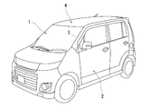
図1に示すように、自動車のフロントウインドガラス1とフロントドア2との間にフロントピラー3が配置され、ルーフ4の前側コーナー部Cにフロントピラー3の上端部が接続している。図2において、42はインストルメントパネル、40はフロントシート、41はリアシートである。
Hereinafter, embodiments of the present invention will be described with reference to the drawings.
As shown in FIG. 1, a
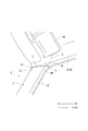
図3,図4に示すように、フロントピラー3は、フロントピラーインナパネル6(車体パネルに相当)と、フロントピラーインナパネル6に取り付けられてフロントピラーインナパネル6の車室内側の面を覆う樹脂製のフロントピラートリム7(下側内装材に相当)とを備え、ルーフ4は、ルーフパネル(車体パネルに相当)と、ルーフパネルに取り付けられてルーフパネルを覆う樹脂製のルーフライニング8(上側内装材に相当)とを備えている。
As shown in FIGS. 3 and 4, the
前記ルーフライニング8は上面視で車両前後方向に長い長方形状に形成され、ルーフライニング8の前側コーナー部Cからフロントピラートリム7に対する接続部9が下方に延びている。前記接続部9の車両前後方向の両側部は車室外側に折曲されて、前側の側壁10と後ろ側の側壁11(図3,図4参照)が前記接続部9に形成されている。ルーフ4の前端部にはサンバイザー14が取り付けられている。
The
図5に示すように、フロントピラートリム7の車両前後方向の両側部が車室外側に折曲されて、前側の側壁12と後ろ側の側壁13が形成されている。そして、図3,図4に示すように、フロントピラートリム7の上端部7J(下側内装材の端部に相当)とルーフライニング8の接続部9の下端部9K(上側内装材の端部に相当)が車幅方向で重ね合わされて接続し、フロントピラートリム7の上端部7Jとルーフライニング8の接続部9の下端部9Kの互いの合わせ部に見切り線Lが形成されている(図3参照)。
As shown in FIG. 5, both side portions of the
また、フロントピラートリム7とフロントピラーインナパネル6の間からルーフライニング8とルーフパネルの間にわたってウォッシャーホースフィーダ線20(索状体に相当)とカーテンエアバッグのテザーベルト21(索状体に相当)が配索されている。
Further, a washer hose feeder line 20 (corresponding to a cord-like body) and a curtain airbag tether belt 21 (corresponding to a cord-like body) are provided between the
ウォッシャーホースフィーダ線20はフロントピラー3の下方からフロントピラー3内を通り、ルーフ4の右側の側部を通って車両後方側Rrまで延びている。このウォッシャーホースフィーダ線20は、クランプ43を介して(図4参照)フロントピラーインナパネル6に固定されており、フロントウインドガラス1やバックウインドガラス43(図2参照)に対する洗浄液噴出ノズルに洗浄液を供給する。
The washer
カーテンエアバッグのテザーベルト21は、カーテンエアバッグのバッグ本体の前端部から延出し、テザーベルト21の先端部側のブラケット48がフロントピラーインナパネル6の幅方向中央部にスクリューSで締結されている(図4参照)。
The
そして、側突時にインフレータからバッグ本体にガスが供給されて前記バッグ本体が下方に膨張展開し、テザーベルト21がバッグ本体によって車両後方側Rrに引っ張られながらフロントピラートリム7の裏側から車室内側に引き出される。これにより、テザーベルト21が位置決め作用位置に位置してバッグ本体の下端部の位置を保持し、バッグ本体が所定の形状に膨張展開した状態で乗員の頭部を保護する。
When a side collision occurs, gas is supplied from the inflator to the bag body, the bag body expands and deploys downward, and the
[突出片15の構造]
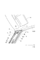
図4,図5に示すように、ルーフライニング8の接続部9の下端部9Kの裏面に、フロントピラーインナパネル6に向かって突出する上面視台形板状の突出片15が一体に設けられ、ウォッシャーホースフィーダ線20が突出片15を避けて、突出片15よりも車両前方側Frのフロントピラーインナパネル6の側部に配索され、テザーベルト21が前記突出片15を避けて、突出片15よりも車両後方側Rrのフロントピラーインナパネル6の側部に配索されている。(図4参照)。
[Structure of protruding piece 15]
As shown in FIGS. 4 and 5, a trapezoidal plate-like projecting
前記突出片15は接続部9の下端部9Kの幅方向(車両前後方向)中央部に位置し、両板面(突出片15の両板面)がウォッシャーホースフィーダ線20とテザーベルト21の長手方向(すなわちフロントピラートリム7の長手方向)を向く状態にルーフライニング8の接続部9の下端部9Kの裏面に設けられている。
The protruding
そして、この突出片15の突出端部15Tがフロントピラーインナパネル6に当接している。フロントピラーインナパネル6と前記接続部9の下端部9Kとは車両後方側Rrほど互いの間隔が狭くなっている。
The projecting
また、フロントピラーインナパネル6に凹部6Uが形成され、突出片15に形成された凸部15Cが前記凹部6Uに嵌合している。凹部6Uと凸部15Cは円弧状に形成されている。これにより、ルーフライニング8の接続部9の下端部9Kがフロントピラーインナパネル6に対してフロントピラー3の幅方向(車両前後方向)に位置ずれすることを防止することができる。
Further, a
図5に示すように、ルーフライニング8の接続部9の下端部9K(図4参照)の裏面には、前記突出片15の基部に連なるリブ47が前記接続部9の下端部9Kのほぼ全幅にわたって突設されている。これにより、突出片15の剛性・強度を向上させることができ、突出片15の耐久性を向上させることができる。図5の符号31はフロントドアオープニングトリムである。
As shown in FIG. 5, on the back surface of the
また、図3,図4に示すように、フロントピラートリム7の上端部7Jをフロントピラーインナパネル6に固定するクリップ用のクリップ孔16が突出片15の下方のフロントピラーインナパネル6に形成されている。突出片15はクリップ孔16に上下方向で近接している。
Further, as shown in FIGS. 3 and 4, a
図5に示すように、フロントピラートリム7の上端部7Jにはフロントピラーインナパネル6側に膨出する断面台形状のクリップ座17が形成され、クリップ座17の座面17Jからクリップ19が突出している。
As shown in FIG. 5, a
上記の自動車においては、カーテンエアバッグがフロントピラーインナパネル6等の車体パネルに取り付けられた後に、ルーフライニング8がルーフパネルに取り付けられ、その後にフロントピラートリム7がフロントピラーインナパネル6に取り付けられる。
In the above-described automobile, the
上記の構成によれば、
(1) 前記ルーフライニング8の接続部9の下端部9Kにフロントピラーインナパネル6に向かって突出する突出片15が設けられ、前記ウォッシャーホースフィーダ線20とテザーベルト21が前記突出片15を避けて配索されているから、前記突出片15でウォッシャーホースフィーダ線20とテザーベルト21の位置規制を行うことができる。
この位置規制を行うことで、ルーフライニング8の接続部9の下端部9Kとフロントピラートリム7の上端部7Jがウォッシャーホースフィーダ線20やテザーベルト21に乗り上げることを防止でき、ルーフライニング8の接続部9の下端部9Kとフロントピラートリム7の上端部7Jの見切り部に隙間が発生することを防止できて、前記見切り部の外観を向上させることができる。
また、前記位置規制を行う手段としては、ルーフライニング8の接続部9の下端部9Kにフロントピラーインナパネル6に向かって突出する突出片15を設けるだけでよく、ルーフライニング8及びフロントピラートリム7の成形型を簡素化できる。従って、成形型の製造コストを低廉化できる。
According to the above configuration,
(1) A protruding
By performing this position restriction, it is possible to prevent the
Further, as a means for regulating the position, it is only necessary to provide a protruding
(2) フロントピラートリム7の上端部7Jをフロントピラーインナパネル6に固定するクリップ用のクリップ孔16が突出片15の下方のフロントピラーインナパネル6に形成されているから、ルーフライニング8の接続部9の下端部9Kをフロントピラーインナパネル6に固定する場合に、ウォッシャーホースフィーダ線20とテザーベルト21がクリップ19とクリップ孔16の間に挟まってしまう不具合を防ぐことができる。
(2) Since the
(3) 例えば、フロントピラートリム7をフロントピラーインナパネル6に取り付ける時に、ルーフライニング8を車室外側に向かって押す力が生じても、突出片15がフロントピラーインナパネル6に当接してルーフライニング8の接続部9の下端部9Kが撓むのを防ぐことができるので、フロントピラートリム7の端部とルーフライニング8の端部との見切り部に隙間ができる不具合を防ぐことができる。
(3) For example, when the front pillar trim 7 is attached to the front pillar
(4) 図6に示すように、テザーベルト21の位置が正規の場所に配索されることなく、例えば、クリップ19よりも車両前方側Frに配置されていると、カーテンエアバッグの展開時にテザーベルト21が矢印A方向(車両後方側Rr)に引っ張られてクリップ19に引っ掛る虞がある。
これに対して、本発明の上記構成によれば、ルーフライニング8の接続部9の下端部9Kにフロントピラートリム7に向かって突出する突出片15が設けられ、前記テザーベルト21が突出片15を避けて配索されているから、前記突出片15でテザーベルト21の位置規制を行うことができて、クリップ19がエアバッグの展開の邪魔になるのを防止できる。
(4) As shown in FIG. 6, when the position of the
On the other hand, according to the above configuration of the present invention, the projecting
[別実施形態]
(1) 上記の構造に加えて、前記突出片15がフロントピラートリム7の上端部7Jの裏面にフロントピラーインナパネル6に向かって突出する状態に設けられていてもよい。
(2) 前記索状体はウォッシャーホースフィーダ線やテザーベルト以外の索状体であってもよい。
[Another embodiment]
(1) In addition to the above structure, the protruding
(2) The cords may be cords other than the washer hose feeder line and the tether belt.
6 車体パネル
6U 凹部(車体パネルに形成された凹部)
7 下側内装材(フロントピラートリム)
7J 下側内装材の端部(フロントピラートリムの上端部)
8 上側内装材(ルーフライニング)
9K 上側内装材の端部(ルーフライニングの接続部の下端部)
15 突出片
15C 凸部(突出片に形成された凸部)
15T 突出片の突出端部
16 クリップ孔
20 索状体(ウォッシャーホースフィーダ線)
21 索状体(テザーベルト)
6
7 Lower interior material (front pillar trim)
7J End of lower interior material (upper end of front pillar trim)
8 Upper interior material (routing)
End of 9K upper interior material (lower end of roof lining connection)
15 Protruding piece 15C Convex part (convex part formed in the projecting piece)
15T Projecting end of projecting
21 Cord (tether belt)
Claims (2)
前記上側内装材の端部と前記下側内装材の端部が接続し、
前記下側内装材と前記車体パネルの間から前記上側内装材と前記車体パネルの間にわたって索状体が配索されている内装材の取り付け構造であって、
前記上側内装材と前記下側内装材の少なくとも一方の内装材の端部に車体パネルに向かって突出する突出片が設けられ、
前記索状体が前記突出片を避けて配索され、
前記突出片は前記上側内装材の端部に設けられ、
前記下側内装材の端部を前記車体パネルに固定するクリップ用のクリップ孔が前記突出片の下方の車体パネルに形成され、
前記突出片の突出端部は前記車体パネルに当接し、
前記車体パネルに形成された凹部に、前記突出片の突出端部に形成された凸部が嵌合している内装材の取り付け構造。 The upper interior material and lower interior material are attached to the body panel,
The end of the upper interior material and the end of the lower interior material are connected,
An interior material mounting structure in which a cord-like body is routed between the lower interior material and the vehicle body panel between the upper interior material and the vehicle body panel,
A protruding piece that protrudes toward the vehicle body panel is provided at an end of at least one of the upper interior material and the lower interior material,
The cords are routed around the protruding pieces,
The protruding piece is provided at an end of the upper interior material,
A clip hole for a clip for fixing an end of the lower interior material to the vehicle body panel is formed in the vehicle body panel below the protruding piece,
The projecting end of the projecting piece abuts the vehicle body panel,
An interior material mounting structure in which a convex portion formed at a protruding end portion of the protruding piece is fitted in a concave portion formed in the vehicle body panel .
前記下側内装材はフロントピラートリム、
前記索状体は頭部保護用エアバッグのテザーベルトである請求項1に記載の内装材の取り付け構造。 The upper interior material is roofing,
The lower interior material is a front pillar trim,
The interior material mounting structure according to claim 1 , wherein the cord-like body is a tether belt of a head protecting airbag.
Priority Applications (3)
| Application Number | Priority Date | Filing Date | Title |
|---|---|---|---|
| JP2010290826A JP5765663B2 (en) | 2010-12-27 | 2010-12-27 | Interior material mounting structure |
| US13/334,252 US8955895B2 (en) | 2010-12-27 | 2011-12-22 | Interior material mounting structure |
| EP11195072.1A EP2468580B1 (en) | 2010-12-27 | 2011-12-22 | Interior material mounting structure |
Applications Claiming Priority (1)
| Application Number | Priority Date | Filing Date | Title |
|---|---|---|---|
| JP2010290826A JP5765663B2 (en) | 2010-12-27 | 2010-12-27 | Interior material mounting structure |
Publications (2)
| Publication Number | Publication Date |
|---|---|
| JP2012136183A JP2012136183A (en) | 2012-07-19 |
| JP5765663B2 true JP5765663B2 (en) | 2015-08-19 |
Family
ID=45444448
Family Applications (1)
| Application Number | Title | Priority Date | Filing Date |
|---|---|---|---|
| JP2010290826A Active JP5765663B2 (en) | 2010-12-27 | 2010-12-27 | Interior material mounting structure |
Country Status (3)
| Country | Link |
|---|---|
| US (1) | US8955895B2 (en) |
| EP (1) | EP2468580B1 (en) |
| JP (1) | JP5765663B2 (en) |
Families Citing this family (5)
| Publication number | Priority date | Publication date | Assignee | Title |
|---|---|---|---|---|
| US8534744B2 (en) * | 2011-09-01 | 2013-09-17 | Toyota Motor Engineering & Manufacturing North America, Inc. | Pillar garnishments, interior garnishment assemblies incorporating the same, and methods for controlling alignment of interior garnishment assemblies |
| JP5971075B2 (en) * | 2012-10-16 | 2016-08-17 | マツダ株式会社 | Automobile front pillar structure |
| JP6167578B2 (en) * | 2013-03-14 | 2017-07-26 | スズキ株式会社 | Curtain airbag storage structure |
| US8919867B2 (en) | 2013-03-14 | 2014-12-30 | Honda Motor Co., Ltd. | Front pillar garnish |
| US11370367B2 (en) * | 2020-05-26 | 2022-06-28 | Ford Global Technology, Llc | Open-frame vehicle having a two-piece trim member |
Family Cites Families (11)
| Publication number | Priority date | Publication date | Assignee | Title |
|---|---|---|---|---|
| EP0170016B1 (en) | 1984-07-05 | 1988-12-07 | Siemens Aktiengesellschaft | Method to compensate the influence of roll excentricities |
| JPS61271148A (en) | 1985-05-27 | 1986-12-01 | Nissan Shatai Co Ltd | End disposition make-up of headlining for vehicle |
| JPH0418048U (en) * | 1990-06-04 | 1992-02-14 | ||
| US5415554A (en) | 1993-10-28 | 1995-05-16 | Prince Corporation | Trim panel connecting link |
| JPH1134755A (en) | 1997-07-24 | 1999-02-09 | Pajiero Seizo Kk | Pillar trim for automobile |
| JP3388574B2 (en) | 1997-09-19 | 2003-03-24 | 矢崎総業株式会社 | Locking structure of electric wire to resin molding |
| JP3879553B2 (en) * | 2002-03-20 | 2007-02-14 | 三菱自動車工業株式会社 | Vehicle occupant protection device |
| JP2004066973A (en) * | 2002-08-07 | 2004-03-04 | Fuji Heavy Ind Ltd | Trim mounting structure for vehicle |
| JP3866733B2 (en) * | 2004-04-27 | 2007-01-10 | 本田技研工業株式会社 | Crew restraint system |
| US7404576B2 (en) * | 2005-04-01 | 2008-07-29 | Nissan Technical Center North America, Inc. | Pillar trim component |
| JP4720449B2 (en) * | 2005-11-14 | 2011-07-13 | スズキ株式会社 | Mounting structure for interior materials around the front pillar of an automobile |
-
2010
- 2010-12-27 JP JP2010290826A patent/JP5765663B2/en active Active
-
2011
- 2011-12-22 US US13/334,252 patent/US8955895B2/en active Active
- 2011-12-22 EP EP11195072.1A patent/EP2468580B1/en active Active
Also Published As
| Publication number | Publication date |
|---|---|
| US8955895B2 (en) | 2015-02-17 |
| US20120161460A1 (en) | 2012-06-28 |
| EP2468580A1 (en) | 2012-06-27 |
| EP2468580B1 (en) | 2015-07-29 |
| JP2012136183A (en) | 2012-07-19 |
Similar Documents
| Publication | Publication Date | Title |
|---|---|---|
| JP4861282B2 (en) | Airbag cover body and airbag device | |
| US9669790B2 (en) | Roof headliner structure in which curtain airbag for vehicle is housed | |
| JP5765663B2 (en) | Interior material mounting structure | |
| US20120119531A1 (en) | Vehicle interior trim panel | |
| JP5096856B2 (en) | Airbag cover body and airbag device | |
| KR20050053116A (en) | Front piller trim mounting structure of vehicle having a curtain type air bag module | |
| JP2010149541A (en) | Airbag device | |
| JP6468530B2 (en) | Deployment structure of automotive curtain airbag | |
| JP4796819B2 (en) | Curtain airbag device | |
| JP4259197B2 (en) | Arrangement structure of head airbag device | |
| JP2009154669A (en) | Cover body for airbag device and airbag device | |
| US10730561B2 (en) | Mounting structure for curtain airbag device | |
| JP2013252800A (en) | Mounting structure of instrument panel | |
| JP5647653B2 (en) | Airbag arrangement structure | |
| JP7196506B2 (en) | Vehicle upper interior structure | |
| JP4802972B2 (en) | Vehicle interior structure | |
| JP5904661B2 (en) | Airbag cover device | |
| JPWO2011162123A1 (en) | Airbag device | |
| JP5321484B2 (en) | Curtain airbag device for vehicle | |
| JP5964798B2 (en) | Curtain airbag device | |
| JP7189497B2 (en) | Vehicle upper interior structure | |
| JP2010095225A (en) | Incorrect attachment prevention structure for front pillar trim | |
| JP4429217B2 (en) | Rail garnish structure of roof side rail | |
| JP6925700B2 (en) | Inner roof structure | |
| KR101394043B1 (en) | Mounting unit for center pillar assembly |
Legal Events
| Date | Code | Title | Description |
|---|---|---|---|
| A621 | Written request for application examination |
Free format text: JAPANESE INTERMEDIATE CODE: A621 Effective date: 20131112 |
|
| A977 | Report on retrieval |
Free format text: JAPANESE INTERMEDIATE CODE: A971007 Effective date: 20140825 |
|
| A131 | Notification of reasons for refusal |
Free format text: JAPANESE INTERMEDIATE CODE: A131 Effective date: 20141001 |
|
| A521 | Written amendment |
Free format text: JAPANESE INTERMEDIATE CODE: A523 Effective date: 20141121 |
|
| A131 | Notification of reasons for refusal |
Free format text: JAPANESE INTERMEDIATE CODE: A131 Effective date: 20150226 |
|
| A521 | Written amendment |
Free format text: JAPANESE INTERMEDIATE CODE: A523 Effective date: 20150420 |
|
| TRDD | Decision of grant or rejection written | ||
| A01 | Written decision to grant a patent or to grant a registration (utility model) |
Free format text: JAPANESE INTERMEDIATE CODE: A01 Effective date: 20150525 |
|
| R151 | Written notification of patent or utility model registration |
Ref document number: 5765663 Country of ref document: JP Free format text: JAPANESE INTERMEDIATE CODE: R151 |
|
| A61 | First payment of annual fees (during grant procedure) |
Free format text: JAPANESE INTERMEDIATE CODE: A61 Effective date: 20150607 |