JP5760785B2 - Image processing apparatus and image processing system - Google Patents
Image processing apparatus and image processing system Download PDFInfo
- Publication number
- JP5760785B2 JP5760785B2 JP2011157181A JP2011157181A JP5760785B2 JP 5760785 B2 JP5760785 B2 JP 5760785B2 JP 2011157181 A JP2011157181 A JP 2011157181A JP 2011157181 A JP2011157181 A JP 2011157181A JP 5760785 B2 JP5760785 B2 JP 5760785B2
- Authority
- JP
- Japan
- Prior art keywords
- image data
- pixel
- color
- data
- difference
- Prior art date
- Legal status (The legal status is an assumption and is not a legal conclusion. Google has not performed a legal analysis and makes no representation as to the accuracy of the status listed.)
- Active
Links
Images

Description
第一の画像出力手段が原稿画像データを出力した第一の出力結果の色調を、第二の画像出力手段が前記原稿画像データを出力した第二の出力結果において再現する画像処理装置に関する。 The present invention relates to an image processing apparatus that reproduces a color tone of a first output result obtained by outputting original image data by a first image output means in a second output result obtained by outputting the original image data by a second image output means.
印刷機やディスプレイなどの画像出力機器では、原稿の画素値に従って印刷されていることが要求される。このため、原稿の画素値と、例えば測色機が印刷物から計測した画素値を比較して、画像出力機器のカラープロファイルを更新する作業が行われることがある。カラープロファイルの更新時には、画像出力機器が、画素値が既知のカラーチャートを出力し、そのカラーチャートをスキャナなどの測色機で測色して、両者を比較し比較結果に基づき画像出力機器のカラープロファイルを更新する方法が広く用いられている(例えば、特許文献1参照。)。 An image output device such as a printer or a display is required to print according to a pixel value of a document. For this reason, an operation of updating the color profile of the image output device by comparing the pixel value of the document with the pixel value measured from the printed matter by the colorimeter, for example, may be performed. When updating the color profile, the image output device outputs a color chart with a known pixel value, measures the color chart with a colorimeter such as a scanner, compares the two, and compares the two based on the comparison result. A method of updating a color profile is widely used (see, for example, Patent Document 1).
このような作業には大きく次の2つのパターンが考えられる。印刷機を例にして説明する。
a) 標準のカラーチャートに色調を合わせるパターン
標準として規定されたカラーチャートを画像出力機器により印刷し、カラーチャートを構成する各カラーパッチを測色機により測色して、画像出力機器等が、得られた測色値と期待される値との差が所定の範囲に収まるように画像出力機器のプリンタ・プロファイルを更新する。
b)基準の画像出力機器に色調を合わせるパターン
一例として、プルーファ(色調の校正機又は校正機と同等の出力物が得られる印刷機)の出力の色調を、画像出力機器の出力の色調に一致させるケースが挙げられる。この場合、カラーチャートをプルーファと画像出力機器とによりそれぞれ印刷し、ユーザは印刷された2つのカラーチャートの各カラーパッチを測色計により測色する。ユーザは、得られた測色値の差が所定の範囲に収まるようにプルーファのプリンタ・プロファイルを更新する。
The following two patterns can be considered for such work. A description will be given using a printing machine as an example.
a) A color chart specified as a pattern standard for adjusting the color tone to the standard color chart is printed by an image output device, each color patch constituting the color chart is measured by a colorimeter, and the image output device, etc. The printer profile of the image output device is updated so that the difference between the obtained colorimetric value and the expected value falls within a predetermined range.
b) As an example of a pattern for matching the color tone to the reference image output device, the color tone of the output of the proofer (a color proofing machine or a printing machine that can obtain an output similar to the proofing machine) matches the color tone of the output of the image output device. There are cases where In this case, the color chart is printed by the proofer and the image output device, respectively, and the user measures the color patches of the two printed color charts by the colorimeter. The user updates the printer profile of the proofer so that the obtained colorimetric value difference falls within a predetermined range.
しかしながら、従来のカラープロファイルの更新方法は、基準のカラーチャートの印刷物が得られない状況下では遂行できないという問題があった。これは、上述したようにある画像出力機器の出力の色調を別の画像出力機器の色調に合わせる場合、双方が同じカラーチャートを出力する必要があるためである。しかし、現実には、基準となる画像出力機器がカラーチャートを出力できないケースや基準となる画像出力機器がカラーチャートを印刷した印刷物を、カラープロファイルを更新する側の画像出力機器が入手できないケースがある。 However, the conventional color profile updating method has a problem that it cannot be performed in a situation where a printed matter of a reference color chart cannot be obtained. This is because when the color tone of the output of one image output device is matched with the color tone of another image output device as described above, both need to output the same color chart. However, in reality, there are cases in which the standard image output device cannot output a color chart, or the reference image output device cannot obtain a printed matter on which the color profile is updated from the printed image on which the color chart is printed. is there.
このケースの一例としては、印刷業者が顧客から印刷業務を受注した際に、顧客のプリンタの出力結果に色調を合わせるように要求されるケースが挙げられる。顧客側でカラーマネージメントが適切に行われていれば、印刷業者はこの様な条件下でも顧客の要求に応えることは可能である。しかしながら、顧客がカラーマネージメントに精通していないケースも少なくない。カラーマネージメントが適切に行われている例としては、画像出力機器のキャリブレーションが定期的に行われていることや、画像データの色がICC(インターナショナル・カラー・コンソーシアム )プロファイルなど標準化された仕組みに基づいて管理されている場合が挙げられる。 As an example of this case, there is a case where when a printing company receives an order for a printing job from a customer, it is required to match the color tone with the output result of the customer's printer. If color management is performed appropriately on the customer side, the printer can respond to the customer's request even under such conditions. However, there are many cases where customers are not familiar with color management. Examples of proper color management include the regular calibration of image output equipment and the standardization of image data colors such as ICC (International Color Consortium) profiles. The case where it is managed based on is mentioned.
カラーチャートが利用できず、また、顧客側でカラーマネージメントが適切に行われていない状況下では、印刷業者は手作業により色合わせを行わなければならない。この作業は試行錯誤で行うため、多大な時間を要すると共に、作業者の経験と勘に依存することから熟練が必要とされる。さらに、色合わせの結果は逐次印刷して確認するため、大量の紙を浪費し、印刷業者が損失を被っている(廃棄される紙は「損紙」と呼ばれる)。 In situations where color charts are not available and color management is not properly performed on the customer side, the printer must perform color matching manually. Since this operation is performed by trial and error, it requires a lot of time and skill because it depends on the experience and intuition of the operator. Furthermore, since the result of color matching is printed and confirmed sequentially, a large amount of paper is wasted and the printer suffers a loss (paper that is discarded is called “scrap paper”).
本発明は、上記課題に鑑み、カラーチャートを用いずに2つの印刷物の色調ズレを、校正することができる画像処理装置を提供することを目的とする。 In view of the above problems, an object of the present invention is to provide an image processing apparatus capable of calibrating the color misalignment between two printed materials without using a color chart.
本発明は、第一の画像出力手段が原稿画像データを出力した第一の出力結果の色調を、第二の画像出力手段が前記原稿画像データを出力した第二の出力結果において再現する画像処理装置であって、読み取り装置が前記第一の出力結果を読み取った第一の出力画像データと前記原稿画像データの位置を合わせる第一の幾何学変換パラメータを推定し、読み取り装置が前記第二の出力結果を読み取った第二の出力画像データと前記原稿画像データの位置を合わせる第二の幾何学変換パラメータを推定する幾何学変換パラメータ推定手段と、前記第一及び第二の幾何学変換パラメータにより対応づけられる、前記第一の出力画像データと前記第二の出力画像データの画素又は画素群の画素値の差分を求めて差分画像データを生成する差分検出手段と、前記差分画像データの画素値と変換後の画素値を対応づけた変換テーブルを参照し、前記差分画像データの画素値が変換された補正画像データを作成する補正処理手段と、前記原稿画像データと前記補正画像データの対応する画素の画素値を算術処理することで前記原稿画像データと前記補正画像データを合成する画像合成手段と、を有することを特徴とする画像処理装置。 The present invention provides an image processing for reproducing the color tone of the first output result obtained by outputting the original image data by the first image output means in the second output result obtained by outputting the original image data by the second image output means. A first geometric transformation parameter for aligning the first output image data obtained by reading the first output result and the position of the original image data, and the reading device A geometric transformation parameter estimating means for estimating a second geometric transformation parameter for aligning the position of the original image data with the second output image data read from the output result, and the first and second geometric transformation parameters. Difference detection means for generating difference image data by obtaining a difference between a pixel value of a pixel or a pixel group of the first output image data and the second output image data to be associated with each other A correction processing unit that creates corrected image data in which pixel values of the difference image data are converted with reference to a conversion table that associates the pixel values of the difference image data with the converted pixel values; and the document image data And image synthesizing means for synthesizing the original image data and the corrected image data by arithmetically processing pixel values of corresponding pixels of the corrected image data.
カラーチャートを用いずに2つの印刷物の色調ズレを、校正することができる画像処理装置を提供することができる。 It is possible to provide an image processing apparatus that can calibrate the color misalignment between two printed materials without using a color chart.
以下、本発明を実施するための形態について図面を参照しながら実施例を挙げて説明する。 DESCRIPTION OF EMBODIMENTS Hereinafter, embodiments for carrying out the present invention will be described with reference to the drawings.
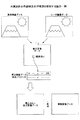
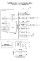
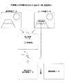
図1は、本実施例の色調補正の特徴部を説明する図の一例である。
左図は、色調合わせの目標となる基準プリンタが原稿画像データを出力した基準画像データである(実際にはスキャナなどで読み取られた画像データ)。
右図は、基準プリンタと色調を同等にしたいユーザプリンタが原稿画像データを出力したユーザ画像データである(実際にはスキャナなどで読み取られた画像データ)。
FIG. 1 is an example of a diagram illustrating a characteristic part of color tone correction according to the present embodiment.
The left figure shows reference image data obtained by outputting original image data from a reference printer which is a target for color tone matching (actually, image data read by a scanner or the like).
The right figure shows user image data output by the user printer whose color tone should be the same as that of the reference printer (original image data read by a scanner or the like).
色調変換システムは、基準画像データとユーザ画像データの差分画像データを作成する。ここでは単純に、基準画像データの画素値からユーザ画像データの画素値を減じる。差分画像データは、基準画像データとユーザ画像データの差なので、この差がなくなるようにユーザ画像データが印刷されればよいことになる。 The color tone conversion system creates difference image data between the reference image data and the user image data. Here, the pixel value of the user image data is simply subtracted from the pixel value of the reference image data. Since the difference image data is the difference between the reference image data and the user image data, the user image data may be printed so that the difference is eliminated.
そこで、色調変換システムは、差分画像データを原稿画像データに反映させる。しかしながら、単に、原稿画像データに差分画像データを加えても、ユーザプリンタが原稿画像データを出力した際に、ユーザ画像データと基準画像データとは同等にならない。これは、一般に、色調再現特性(入力された色をどのような色として出力するか)は線形ではないため、原稿画像データに差分画像データを加えるという線形な反映方法が、色調再現特性と適合しないためである。 Therefore, the color tone conversion system reflects the difference image data in the document image data. However, simply adding difference image data to document image data does not make the user image data and reference image data equivalent when the user printer outputs document image data. In general, the color tone reproduction characteristics (what color the input color is output as) are not linear, so the linear reflection method of adding difference image data to the original image data is compatible with the color tone reproduction characteristics. It is because it does not.
このため、本実施例の色調変換システムは、差分画像データを画素毎又は画素群毎に補正する。そこで、予めLUT(後述する補正パラメータ)を用意しておくことにする。 For this reason, the color tone conversion system of the present embodiment corrects the difference image data for each pixel or each pixel group. Therefore, an LUT (correction parameter described later) is prepared in advance.
例えば、差分画像データのある画素の画素値がcの場合、cに対応づけられた値を補正後の画素値c´とする。 For example, when the pixel value of a certain pixel in the difference image data is c, a value associated with c is set as a corrected pixel value c ′.
補正後の画素値c´に色調変換したと仮定すれば、基準画像データとユーザ画像データの差分に等しくなると期待できる。よって、色調変換システムは、上記の補正を差分画像データの画素毎又は画素群毎に行った補正後の差分画像データ(以下、補正画像データという)を、原稿画像データに加算する。本実施例では、この補正画像データの原稿画像データへの画素値の加算を画像データの合成という。ユーザプリンタが合成後の原稿画像データを出力したユーザ画像データは、基準画像データと同等になることが期待できる。 If it is assumed that the tone has been converted to the corrected pixel value c ′, it can be expected to be equal to the difference between the reference image data and the user image data. Therefore, the color tone conversion system adds the corrected differential image data (hereinafter referred to as corrected image data) obtained by performing the above correction for each pixel or pixel group of the differential image data to the document image data. In this embodiment, the addition of the pixel value to the original image data of the corrected image data is called image data synthesis. The user image data from which the user printer has output the synthesized original image data can be expected to be equivalent to the reference image data.
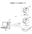
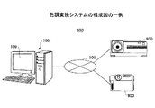
図2は、色調変換システム610の構成図の一例を示す。機器や画像データを以下のように定義する。
・第一の画像出力機器:プリンタ (「基準プリンタ」と呼ぶ)
・第二の画像出力機器:プリンタ (「ユーザプリンタ」と呼ぶ)
・画像読取装置:スキャナ
また、以降で使用する用語を以下のように定義する。
・基準プリンタ:第一の画像出力機器に対応し、色調が合わせられる目標となるプリンタ
・ユーザプリンタ:第二の画像出力機器に対応し、基準プリンタ400に色調を合わせたいプリンタ
・スキャナ:画像読取装置に対応
・原稿画像データ:プリンタが印刷物を出力する際に用いる画像データ
・基準印刷物:原稿画像データを基準プリンタ400で出力した、色調合わせの目標とされる印刷物
・基準画像データ:基準印刷物を画像読取装置で読み取って得られる画像データ
・ユーザ印刷物:原稿画像データをユーザプリンタ200で出力した、基準印刷物に色調を合わせたい印刷物
・ユーザ画像データ:ユーザ印刷物を画像読取装置で読み取って得られる画像データ
本実施形態では、基準印刷物とユーザ印刷物とを用い、ユーザプリンタ200に与える原稿画像データに色調変換を行うことによって、基準印刷物の色調と同等の色調のユーザ印刷物が得られるようにする。
FIG. 2 shows an example of a configuration diagram of the color
First image output device: Printer (referred to as “reference printer”)
Second image output device: Printer (referred to as “user printer”)
-Image reading device: scanner The terms used in the following are defined as follows.
Reference printer: a printer that corresponds to the first image output device and is a target to be adjusted in color tone. User printer: a printer that corresponds to the second image output device and wants to adjust the color tone to the
色調変換を行う装置は、第二の画像出力機器でもスキャナ300でもよいし、これらとは別体のコンピュータ100でもよい。本実施形態では、コンピュータ100が原稿画像データと補正画像データを合成するものとして説明する。
The apparatus that performs color tone conversion may be the second image output device or the
図2に示した色調変換システム610は、ネットワーク500を介して接続された、コンピュータ100、ユーザプリンタ200、及び、スキャナ300を有する。ユーザプリンタ200の代わりにオフセット印刷機やグラビア印刷機などを用いてもよく、また、スキャナ300の変わりに分光測色器やカメラを用いてもよい。基準プリンタ400は、色調変換システム610のユーザ側に存在しないことを想定しているためネットワークに接続されていないが、接続されていてもよい。色調変換システム610のユーザは、基準プリンタ400が基準画像データを出力した基準印刷物をすでに取得しているか、取得することができる。
A color
ネットワークは、社内LAN、広域LAN(WAN)、IP−VNP(Virtual Private Network)、インターネットVPN、又は、インターネットなどである。これらが組み合わされたネットワーク等、コンピュータ100、ユーザプリンタ200、及び、スキャナ300が通信可能であればよい。一部に電話回線を含んでいてもよく、また、有線接続か無線接続は問わない。
The network is an in-house LAN, a wide area LAN (WAN), an IP-VNP (Virtual Private Network), the Internet VPN, the Internet, or the like. It is sufficient that the
なお、同じ一台のプリンタで過去と現在の色調を合わせる場合など、基準プリンタ400とユーザプリンタ200はそれぞれ異なる装置である必要はない。また、基準プリンタ400及びユーザプリンタ200は、プリンタ機能を有していれば、スキャナ機能、FAX機能及びコピー機能の1つ以上を有していてもよい。同様に、スキャナ300は、スキャナ機能を有していれば、プリンタ機能、FAX機能及びコピー機能の1つ以上を有していてもよい。複数の機能を有する装置はMFP(Multifunction Peripheral)と称されることがある。
Note that the
また、コンピュータ100は、基準印刷物をスキャナ300が読み取った基準画像データ、及び、ユーザプリンタ200が原稿画像データを出力したユーザ印刷物をスキャナ300が読み取ったユーザ画像データから差分画像データを生成し、これを補正した後、原稿画像データに合成する。原稿画像データは、ユーザプリンタ200が予め記憶しておいてもよいし、基準プリンタ400から取得してもよい。コンピュータ100、ユーザプリンタ200、及び、スキャナ300は一台のMFPに搭載することもできる。
Further, the
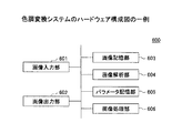
図3は、色調変換システム610のハードウェア構成図の一例を示す。色調変換システム610は、画像入力部601、画像出力部602、画像記憶部603、画像解析部604、パラメータ記憶部605、及び、画像処理部606を有する。
FIG. 3 shows an example of a hardware configuration diagram of the color
画像入力部601は、画像出力機器により出力された画像を入力するものであり、図2ではスキャナ300が相当する。画像記憶部603は、画像入力部601が入力を受け付けた画像データを記憶するものであり、図2ではコンピュータ100が相当する。画像解析部604は、基準画像データ、ユーザ画像データ、及び、原稿画像データから補正画像データを生成し、補正画像データと原稿画像データを合成して補正済み原稿画像データを生成する。図2ではコンピュータ100が相当する。パラメータ記憶部605は、差分画像データ、補正画像データ、補正済み原稿画像データ、LUT等を記憶するもので、図2ではコンピュータ100が相当する。画像処理部606は、得られた補正済み原稿画像データを画像処理するもので、図2ではユーザプリンタ200が相当する。画像出力部602は、補正済み原稿画像データを出力するもので、図2ではユーザプリンタ200が相当する。
The
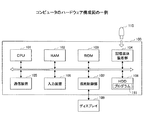
図4は、コンピュータ100のハードウェア構成図の一例を示す。コンピュータ100はそれぞれバスで相互に接続されているCPU101、RAM102、ROM103、記憶媒体装着部104、通信装置105、入力装置106、描画制御部107、及び、HDD108を有する。CPU101は、OS(Operating System)やプログラムをHDD108から読み出して実行することで種々の機能を提供すると共に、補正済み原稿画像データの生成処理を行う。
FIG. 4 shows an example of a hardware configuration diagram of the
RAM102はCPU101がプログラムを実行する際に必要なデータを一時保管する作業メモリ(主記憶メモリ)になり、ROM103はBIOS(Basic Input Output System)やOSを起動するためのプログラム、静的なデータが記憶されている。
The
記憶媒体装着部104には記憶媒体110が着脱可能であり、記憶媒体110に記録されたプログラムを読み込み、HDD108に記憶させる。また、記憶媒体装着部104は、HDD108に記憶されたデータを記憶媒体110に書き込むこともできる。記憶媒体110は例えば、USDメモリ、SDカード等である。
A
入力装置106は、キーボードやマウス、トラックボールなどであり、コンピュータ100へのユーザの様々な操作指示を受け付ける。
The
HDD108は、SSD等の不揮発メモリでもよく、OS、プログラム、画像データなどの各種のデータが記憶されている。 The HDD 108 may be a nonvolatile memory such as an SSD and stores various data such as an OS, a program, and image data.
通信装置105は、インターネットなどのネットワーク301に接続するためのNIC(Network Interface Card)であり、例えば、イーサネット(登録商標)カードである。
The
描画制御部107は、CPU101がプログラム111を実行してグラフィックメモリに書き込んだ描画コマンドを解釈して、画面を生成しディスプレイ109に描画する。
The
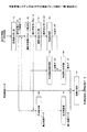
図5は、色調変換システム610を一台のMFP700で実現した場合の、MFP700のハードウェア構成図の一例を示す。MFP700は、コントローラ30、操作部31、ファックス制御ユニット32、プロッタ33、スキャナ34、及び、その他ハードウェアリソース35を有する。コントローラ30は、CPU11,MEM−P12,NB(ノースブリッジ)13、ASIC16,MEM−C14,HDD15(Hard Disk Drive)、及び、PCIバスを介してNB13と接続された周辺機器17を有する。
FIG. 5 shows an example of a hardware configuration diagram of the
コントローラ30において、ASIC16にはMEM−C14、HDD15、及び、NB13が接続されると共に、NB13にはCPU11とMEM−P12が接続されている。NB13はCPUチップセットの1つであり、CPU11,MEM−P12,ASIC16,及び、周辺機器を接続するためのブリッジである。
In the
ASIC16は、画像処理用途向けのICであり各種の画像処理を行う。ASIC16は、AGP、HDD15、及び、MEM−C14をそれぞれ接続するブリッジの役割も果たす。CPU11は、MFP700の全体制御を行うと共にMFP700に実装されている各種アプリケーションを起動して実行させる。
The
MEM−P12は、MFP700のシステムが使用するシステムメモリであり、MEM−C14は、画像処理中の画像データのバッファとして用いられるローカルメモリである。
The MEM-
HDD15は、大容量のストレージであり、SSD(Solid State Drive)などを用いてもよい。HDD15には、OS、各種のアプリケーション、フォントデータ等が記憶される。また、HDD15には補正済み原稿画像データの生成処理を行うプログラム23が記憶されている。
The
周辺機器17は、シリアルバス、NIC、USBホスト、IEEE802.11a/b/g/n、IEEE1394、及び、メモリカードI/Fである。シリアルバスには、例えばセントロニクスケーブルが接続される。NICはネットワークを介した通信を制御する。USBホストにはUSBケーブルを介して機器が接続される。IEEE802.11a/b/g/nはこれらの規格に従った無線LAN用のインタフェースであり、無線LANによる通信を制御する。IEEE1394は、高速なシリアル通信を制御するインタフェースである。メモリカードI/Fには各種のメモリカードが装着され、データの読み書きを行う。メモリカードは、例えば、SDカード、マルチメディアカード、xDカード等である。
The
操作部31は、ハード的なキーボードと液晶などの表示手段とを有する。操作部31は、ユーザからの入力操作の受け付け、ユーザに向けた各種の画面の表示をおこなう。操作部31はタッチパネルを搭載しており、表示したソフトキーからユーザ操作を受け付けることもできる。
The
ファックス制御ユニット32は、NCU(Network Control Unit)を介して公衆通信網に接続し、例えばG3、G4規格のファクシミリに対応した通信手順(通信プロトコル)等に従いファクシミリの送受信を行う。ファックス制御ユニット32は、画像データにデータ圧縮や変調等の信号処理を施して送信すると共に、相手先から受信した画像データにデータの伸長やエラー訂正等を施し画像データを復元する。
The
プロッタ33は、例えば、電子写真方式による白黒プロッタ又はカラープロッタであり、印刷対象データやスキャナ34が読み取った画像データに基づき、1ページ毎の画像を形成し、用紙に転写する。例えば、レーザービームを用いた電子写真プロセスを使って、感光ドラム等に形成したトナー画像を用紙に転写し、定着装置により熱と圧力により定着して出力する。また、インク液滴を塗布する形態で印刷してもよい。
The
スキャナ34は、コンタクトガラスに載置された原稿を光学的に走査して、その反射光をA/D変換して公知の画像処理を施し所定の解像度のデジタルデータに変換し画像データを生成する。
The
図5のMFP700では、図3の画像入力部601はスキャナ34が相当し、画像出力部602はプロッタ33が相当し、画像記憶部603はHDD15が相当し、画像解析部604はCPU11が相当し、パラメータ記憶部605はHDD15が相当し、画像処理部606はASIC16が相当する。
In the
図6は、本実施例の色調変換システム610又はMFP700の機能ブロック図の一例である。本実施例の色調変換システム610は、画像読み取り部41、幾何学変換パラメータ推定部42、差分検出部61、補正処理部62、及び、画像合成部63を有する。
FIG. 6 is an example of a functional block diagram of the color
画像読み取り部41は原稿画像データの出力結果である基準印刷物及びユーザ印刷物を読み取り、基準画像データ及びユーザ画像データを生成する。
The
幾何学変換パラメータ推定部42は原稿画像データと基準画像データ、原稿画像データとユーザ画像データのそれぞれの幾何学変換パラメータを推定する。
The geometric conversion
差分検出部61は、基準画像データとユーザ画像データの間の差分を検出し、差分画像データを生成する。
The
補正処理部62は、所定の補正パラメータを用いて差分画像データに補正処理を施し、補正画像データを生成する。補正処理部62は補正パラメータを記憶している。補正パラメータは実際にはHDD108、15に記憶されている。
The
画像合成部63は、原稿画像データと補正画像データとを合成して、補正済み原稿画像データを生成する。
The
〔動作手順〕
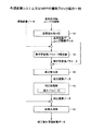
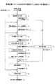
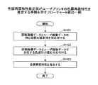
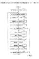
図7は、色調変換システム610又はMFP700が色調補正する手順を示すフローチャート図の一例である。
[Operation procedure]
FIG. 7 is an example of a flowchart illustrating a procedure in which the color
画像読み取り部41は、基準印刷物を読み取り、基準画像データを生成する(S110)。
The
ユーザプリンタ200が、原稿画像データを印刷してユーザ印刷物を出力する(S120)。
The
画像読み取り部41が、ユーザ印刷物を読み取り、ユーザ画像データを生成する(S130)。基準印刷物とユーザ印刷物とを同じスキャナで読み取ってもよいし、スキャナのカラープロファイルを用いてデバイス非依存の色空間に変換できるという条件の元で、二つの印刷物を別々のスキャナで読み取ってもよい。
The
次に、幾何学変換パラメータ推定部42は、基準画像データとユーザ画像データとを原稿画像データに位置合わせする(S140)。すなわち、原稿画像データを基準とし、基準画像データとユーザ画像データの幾何学変換パラメータをそれぞれ求め、幾何学変換パラメータを用いて位置合わせを行う。幾何学変換パラメータの例としては、変位量、回転角、変倍率がある。
Next, the geometric transformation
幾何学パラメータの推定には公知の技術を用いればよい。その例としては、マーカーを用いる方法や、マーカーを用いないパターンマッチング法や位相限定相関法などが挙げられる。
a) マーカーを用いる方法
「トンボ」と呼ばれるマーカーを原稿画像データの四隅や各辺の中央に配置したうえで出力し、基準画像データとユーザ印刷物を読み取った際に、このトンボマーカの位置のずれを用いて、変位量や回転角、変倍率を求める。
A known technique may be used to estimate the geometric parameter. Examples thereof include a method using a marker, a pattern matching method not using a marker, a phase-only correlation method, and the like.
a) Marker method A marker called `` Register Mark '' is placed at the four corners and the center of each side of the original image data and output, and when the reference image data and user print are read, the misalignment of this register mark marker is detected. Using this method, the amount of displacement, rotation angle, and variable magnification are obtained.
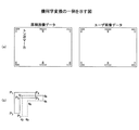
図8(a)はトンボマーカの一例を示す図である。1枚の記録紙に画像データと4つ〜6つのトンボが形成されている。原稿画像データとユーザ画像データとで、トンボと画像データの相対的位置が同じであるとすると、同じ位置の2つのトンボの位置ずれを比較することで、幾何学変換パラメータを求めることができる。なお、例えば紙端からのトンボのおよその位置は既知なので、紙端から所定範囲にトンボの検出処理を施せばトンボの位置を検出できる。 FIG. 8A is a diagram illustrating an example of a registration mark marker. Image data and four to six registration marks are formed on one recording sheet. Assuming that the relative positions of the registration marks and the image data are the same between the document image data and the user image data, the geometric conversion parameters can be obtained by comparing the positional deviations of the two registration marks at the same positions. For example, since the approximate position of the registration mark from the paper edge is known, the registration mark position can be detected by performing registration mark detection processing within a predetermined range from the paper edge.
図8(b)はトンボマーカの位置のずれについて説明する図の一例である。Pn(nは1以上の整数)は原稿画像データのトンボマーカの特徴点の位置を、qnは基準画像データのトンボマーカの特徴点の位置を、それぞれ示す。位置ずれがなければP1とq1、P2とq2、P3とq3…の点どうしの位置が一致するはずなので、公知の手法により点どうしの対応関係を求めることで、幾何学変換パラメータが得られる。ここで、2つの画像のうち一方の画像に例えばアフィン変換を行うことで2つの点パターンをマッチングさせることが知られている。したがって、幾何学変換パラメータを求めるには、2つの点パターンの各位置が最も近似する最適なアフィンパラメータを探し出せばよい。例えば、P1〜P6にアフィン変換するためのアフィンパラメータの評価関数を定め、評価関数が最小になるときのアフィンパラメータを幾何学変換パラメータとする。
b) パターンマッチング法を用いる方法
変位量のみを推定する方法の一例としては、テンプレートマッチング法が挙げられる。テンプレートマッチング法は一方の画像をテンプレートとし、位置を少しずつずらしながら他方の画像と一致度を求め、最も一致度の高くなる位置を検出するものである。幾何学変換が変位だけに限定できない場合には、回転角を推定する方法(ハフ変換など)や変倍量を推定する方法(マルチスケール解析など)と組み合わせて利用する必要がある。
FIG. 8B is an example of a diagram for explaining the displacement of the registration mark marker position. Pn (n is an integer equal to or greater than 1) indicates the position of the feature point of the registration mark marker in the document image data, and qn indicates the position of the feature point of the registration mark marker in the reference image data. If there is no misalignment, the positions of the points of P1 and q1, P2 and q2, P3 and q3,... Should match, and the geometric transformation parameters can be obtained by obtaining the correspondence between the points by a known method. Here, it is known to match two point patterns by performing, for example, affine transformation on one of the two images. Therefore, in order to obtain the geometric transformation parameter, it is only necessary to find an optimal affine parameter that approximates each position of the two point patterns. For example, an affine parameter evaluation function for affine transformation is defined as P1 to P6, and the affine parameter when the evaluation function is minimized is used as the geometric transformation parameter.
b) Method using pattern matching method An example of a method for estimating only the displacement is a template matching method. In the template matching method, one image is used as a template, the degree of coincidence with the other image is obtained while gradually shifting the position, and the position with the highest degree of coincidence is detected. When the geometric transformation cannot be limited to only displacement, it is necessary to use in combination with a method for estimating the rotation angle (such as Hough transform) or a method for estimating the amount of magnification (such as multi-scale analysis).
テンプレートマッチングを応用したブロックマッチング法では、一方の画像をブロックに分割し、ブロックごとに他方の画像と最も一致度の高くなる位置を検出することにより変位量を求めることができる。ブロックマッチング法では、ブロックごとの変位量から回転角や変倍率を推定することも可能である。
c) 位相限定相関法を用いる方法
高い精度で変位量や回転角、変倍率を求める方法の例として、位相限定相関法(POC、Phase Only Correlation)や回転不変位相限定相関法(RIPOC、Rotation Invariant Phase Only Correlation)がある。位相限定相関法は、画像に対して離散フーリエ変換をかけて得られる位相画像を用い、比較対象の二枚の画像から得られる二つの位相画像の相関が最も高くなる位置を検出することにより、変位量を求める手法である。また、回転不変位相限定相関法は、上記位相画像を対数極座標変換することにより、回転角と変倍率を変換された位相画像上での変位量として検出できるようにしたものである。
In the block matching method using template matching, one image is divided into blocks, and the displacement amount can be obtained by detecting the position having the highest degree of coincidence with the other image for each block. In the block matching method, it is also possible to estimate the rotation angle and magnification from the displacement amount for each block.
c) Method using phase-only correlation method Examples of methods for obtaining displacement, rotation angle, and scaling factor with high accuracy include phase-only correlation (POC) and rotation-invariant phase-only correlation (RIPOC, Rotation Invariant). Phase Only Correlation). The phase only correlation method uses a phase image obtained by subjecting an image to a discrete Fourier transform, and detects a position where the correlation between two phase images obtained from two images to be compared is highest, This is a method for obtaining a displacement amount. The rotation-invariant phase-only correlation method is such that the rotation angle and the scaling factor can be detected as a displacement amount on the converted phase image by logarithmic polar coordinate conversion of the phase image.
なお、原稿画像データと基準画像データ、及び、原稿画像データとユーザ画像データ、それぞれの幾何学変換パラメータが求められると、基準画像データとユーザ画像データも位置合わせされる。 When the geometric image conversion parameters of the original image data and the reference image data, and the original image data and the user image data are obtained, the reference image data and the user image data are also aligned.
また、原稿画像データと基準画像データの幾何学変換パラメータを求め、基準画像データとユーザ画像データの幾何学変換パラメータを求めることで、原稿画像データとユーザ画像データも位置あわせされる。 Further, by obtaining the geometric conversion parameters of the document image data and the reference image data and by obtaining the geometric conversion parameters of the reference image data and the user image data, the document image data and the user image data are also aligned.
同様に、原稿画像データとユーザ画像データの幾何学変換パラメータを求め、ユーザ画像データと基準画像データの幾何学変換パラメータを求めることで、原稿画像データとユーザ画像データも位置あわせされる。すなわち、幾何学変換パラメータは2つ求めておけば、3つの画像データのうち任意の2つの画像データが位置あわせされる。 Similarly, the original image data and the user image data are also aligned by obtaining the geometric conversion parameters of the original image data and the user image data and obtaining the geometric conversion parameters of the user image data and the reference image data. That is, if two geometric transformation parameters are obtained, any two image data out of the three image data are aligned.
以上により幾何学変換パラメータが求まったら、幾何学変換パラメータ推定部42は基準画像データ(又はユーザ画像データ)に幾何学変換を実行する。変換に際してサブピクセル精度の移動や何らかの回転、実数値での変倍などにより変換前後の画素が一対一で対応付かないようなケースでは、適宜画素補間手法を用いて画素値を導出すればよい。画素補間手法の例としては、バイリニア法、バイキュービック法などが挙げられる。
When the geometric transformation parameters are obtained as described above, the geometric transformation
なお、幾何学変換は必須ではなく、次ステップにおいて原稿画像データと基準画像データ(又はユーザ画像データ)において同じ位置の画素を取得する際に、幾何学変換パラメータを用いて座標変換を行い、同じ位置か否かを判断することによって代替してもよい。後者を換言すれば、各画像の原点を基準とする座標系では異なる座標値を保持していても、幾何学変換の結果、同じ座標値となる画素を「同じ位置の画素」と見なすことになる。 Note that geometric conversion is not essential, and when the pixels at the same position in the original image data and the reference image data (or user image data) are acquired in the next step, coordinate conversion is performed using the geometric conversion parameters. You may substitute by judging whether it is a position. In other words, even if the coordinate system based on the origin of each image holds different coordinate values, the pixels with the same coordinate value as a result of geometric transformation are regarded as “pixels at the same position”. Become.
原稿画像データを出力して得られた印刷物には画像の周囲に余白が存在するケースが存在する。この様なケースでは、幾何学変換の変位量に余白部分の高さや幅が含まれるため余白部分を参照することはないが、出力画像データにおいて余白部分を排除するように必要な領域を切り出し、各画像における原点の位置を一致させてもよい。 There are cases where margins exist around the printed material obtained by outputting the document image data. In such a case, since the height and width of the margin part are included in the displacement amount of the geometric transformation, the margin part is not referred to, but a necessary area is cut out in the output image data so as to exclude the margin part, You may make the position of the origin in each image correspond.
図7に戻り、差分検出部61は、ユーザ印刷物を評価する(S150)。そして、ユーザ印刷物が妥当か否かを判定する(S160)。
Returning to FIG. 7, the
ユーザ印刷物の品質が十分であれば(S160のYes)、処理を終了し、そうでなければ(S160のNo)、次ステップS170に進む。 If the quality of the user printed material is sufficient (Yes in S160), the process ends. If not (No in S160), the process proceeds to the next step S170.
ユーザ印刷物の品質を評価する方法の例としては、基準印刷物との色差を用いる方法がある。他の例としては、色相差を用いる方法や、各色成分の差の絶対値を用いる方法もある。なお、品質の評価は目視で行ってもよい。
a) 色差を用いる評価方法
色差とは、L*a*b*色空間やL*u*v*色空間における二つの色の距離である。本実施例は画像出力機器としてプリンタを用いていることからL*a*b*色空間を用いて説明する。
L*a*b*色空間の色差ΔE* abは以下の式で定義される。
As an example of a method for evaluating the quality of a user print, there is a method using a color difference from a reference print. Other examples include a method using a hue difference and a method using an absolute value of a difference between each color component. The quality evaluation may be performed visually.
a) Evaluation method using color difference Color difference is the distance between two colors in L * a * b * color space or L * u * v * color space. Since this embodiment uses a printer as an image output device, an explanation will be given using the L * a * b * color space.
The color difference ΔE * ab in the L * a * b * color space is defined by the following equation.

基準印刷物とユーザ印刷物の色差を求める手順の一例を以下に示す。
(1)基準印刷物をスキャナ300により読み取り基準画像データを得る
(2)ユーザ印刷物を(1)と同じスキャナ300により読み取りユーザ画像データを得る
(3)基準画像データとユーザ画像データとをスキャナ300のカラープロファイルを用いてデバイス非依存の色空間(XYZ色空間など)に変換する
(4)デバイス非依存の色空間に変換された基準画像データとユーザ画像データとをL*a*b*色空間に変換する
(5)上式により画素ごとの色差を求める
基準印刷物とユーザ印刷物とを同じスキャナ300で読み取るとしているが、スキャナ300のカラープロファイルを用いてデバイス非依存の色空間に変換できる条件の元で、二つの印刷物を別々のスキャナ300で読み取ってもよい。
An example of the procedure for obtaining the color difference between the reference print and the user print is shown below.
(1) A reference print is read by the
スキャナ300を一台のみ使用する場合には、カラープロファイルを用いてデバイス非依存の色空間に変換することは必須ではない。色差の値を定量的に評価するケースでは、絶対的な値が重要であるためデバイス非依存の色空間への変換が必要であるが、色差の値を定性的に評価するケースでは相対的な傾向がつかめればよいためデバイス非依存の色空間への変換を省略してもよい。
When only one
画素ごとの色差が求まったら、この情報を統計的に分析し、ユーザ印刷物の品質を定量的に評価することができる。分析方法の例としては、色差の平均値、最大値、値の分布、分散などが挙げられる。 Once the color difference for each pixel is found, this information can be statistically analyzed to quantitatively evaluate the quality of the user print. Examples of the analysis method include an average value, maximum value, value distribution, and variance of color differences.
品質が十分であるか否かの判断は、
・平均色差が所定の値以内に収まっているか否か、
・最大色差が所定の値以内に収まっているか否か、
・分散が所定の値以内に収まっているか否か、
などの基準で判断することができる。なお、ユーザ印刷物の品質を評価する際には、画像データのコンテンツの輪郭部分を除くことが望ましい。これは、
・後の処理で必要な位置合わせにおいて、輪郭部分を完全に合わせることが困難であること、
・プリンタによって輪郭部分の再現性が異なること (色味やシャープなど)
などの理由から、輪郭部分で大きな色差が出現する可能性があるためである。
The judgment of whether the quality is sufficient is
-Whether the average color difference is within a predetermined value,
-Whether the maximum color difference is within a predetermined value,
・ Whether the variance is within the prescribed value,
It can be judged by such criteria. When evaluating the quality of user prints, it is desirable to remove the outline portion of the content of the image data. this is,
・ It is difficult to perfectly align the contours in the alignment required for later processing.
・ The reproducibility of the contour varies depending on the printer (color, sharpness, etc.)
This is because there is a possibility that a large color difference appears in the contour portion.
輪郭部分の面積は全印刷物の面積のごく一部であるため、目視による全体的な色調の評価に与える影響は限定的である。一方、定量的な評価においては、上述の輪郭部分の大きな色差が外れ値として評価結果の信頼性を低下させる懸念があることから、輪郭部分のデータを無視する方が高い精度の評価結果が期待できる。 Since the area of the contour portion is only a part of the area of the entire printed matter, the influence on the overall color tone evaluation by visual inspection is limited. On the other hand, in quantitative evaluation, there is a concern that the large color difference of the contour portion described above may be an outlier and reduce the reliability of the evaluation result. it can.
輪郭部分を検出する方法の例としては、二値化を用いる方法や、エッジ検出を用いる方法が挙げられる。二値化を用いる方法の一例としては、画像データを所定の閾値で白黒に二値化し、白い領域と黒い領域とが隣接する箇所を輪郭部分として判断する方法がある。エッジ検出を用いる方法の一例としては、画像データからSobel法などを用いてエッジ画像を作成し、これを所定の閾値で二値化して閾値以上の画素を輪郭部分として判断する方法がある。 Examples of the method for detecting the contour portion include a method using binarization and a method using edge detection. As an example of a method using binarization, there is a method in which image data is binarized into black and white with a predetermined threshold, and a portion where a white region and a black region are adjacent is determined as a contour portion. As an example of a method using edge detection, there is a method in which an edge image is created from image data by using a Sobel method or the like, and this is binarized with a predetermined threshold value, and pixels above the threshold value are determined as contour portions.
輪郭部分を除去せずに、上記課題を緩和する方法もある。例えば、画像データを平滑化して輪郭部分を滑らかにし、輪郭部分で出現する色差を低減するというものである。平滑化には、平均化フィルタやローパスフィルタなど従来技術を用いればよい。 There is also a method for alleviating the above problem without removing the contour portion. For example, the image data is smoothed to smooth the contour portion, and the color difference appearing at the contour portion is reduced. For smoothing, a conventional technique such as an averaging filter or a low-pass filter may be used.
b)色相差を用いる評価方法
L*a*b*色空間の色相差ΔH* abは次式で定義される。
b) Evaluation method using hue difference
The hue difference ΔH * ab in the L * a * b * color space is defined by the following equation.
c)各色成分の差の絶対値を用いる評価方法
所定の色空間において、基準印刷物とユーザ印刷物との各色成分の差の絶対値を取り、評価を行う方法である。RGB色空間を例に取れば、R成分値の絶対値の差、G成分値の絶対値の差、B成分値の絶対値の差を用いる。
基準印刷物とユーザ印刷物の各色成分の差の絶対値を求める手順の一例を以下に示す。
c) Evaluation method using absolute value of difference of each color component In this method, the absolute value of the difference of each color component between the reference print and the user print is taken and evaluated in a predetermined color space. Taking the RGB color space as an example, the difference between the absolute values of the R component values, the difference between the absolute values of the G component values, and the difference between the absolute values of the B component values are used.
An example of a procedure for obtaining the absolute value of the difference between the color components of the reference print and the user print is shown below.
(1)基準印刷物をスキャナ300により読み取り基準画像データを得る
(2)ユーザ印刷物を(1)と同じスキャナ300により読み取りユーザ画像データを得る
(3)基準画像データとユーザ画像データとをスキャナ300のカラープロファイルを用いてデバイス非依存の色空間(XYZ色空間など)に変換する
(4)変換後の色空間において、画素ごとに各色成分値の差の絶対値を求める。
なお、色差のケースと同様に、スキャナ300のカラープロファイルを用いてデバイス非依存の色空間に変換することは必須ではなく、スキャナ300のデバイス依存の色空間で直接差の絶対値を求めてもよい。また、統計的な分析方法や品質の判定方法は色差のケースと同様である。
(1) A reference print is read by the
As in the case of the color difference, conversion to a device-independent color space using the color profile of the
次に、差分検出部61は、差分画像データを生成する(S170)。すなわち、基準画像データに対するユーザ画像データの画素値の差を画像データ全体に渡って求め、差分画像データを生成する。基準画像データとユーザ画像データとを位置合わせしてれば、同じ座標に存在する画素の画素値の差を取ればよいし、幾何学変換パラメータのみを求めてあるのであれば幾何学変換後の座標が対応する画素の画素値の差を取ればよい。なお、画素値の差は画素単位で求めてもよいし、複数の画素で構成される領域ごとに領域内の平均画素値の差を求めて代替してもよい。また、画素値の差は符号まで含めて記録する。
Next, the
次に、補正処理部62は、差分画像データを補正する(S180)。すなわち、所定の補正パラメータを用いて差分画像データに補正処理を施し、補正画像データを得る。補正パラメータを予め容易しておく方法の例としては、ユーザが任意の値を指定しておく方法と、十分な階調数を持った画像を用いて事前に決定しておく方法がある。後者の方法は、補正パラメータを動的に決定する場合と基本的に同じであるため、実施例2にて説明する。十分な階調数を持った画像を用いる理由は、推定される補正パラメータの精度を高めるためである。カラーチャートも一般に十分な階調数を持っているため、この目的に合致するので、使用してもよい。
Next, the
本実施例では、補正パラメータは、γ補正やルック・アップ・テーブルの形式で予め定められているものとする。したがって、γ補正やルック・アップ・テーブルの変換がそのまま補正処理となる。すなわち、補正パラメータは、ガンマ補正であればガンマの値(出力=入力γとした時のγと、差分画像データの画素値を対応づける)、LUTであればテーブルそのもの(差分画像データの画素値に補正後の差分画像データの値を対応づける)である。 In this embodiment, it is assumed that the correction parameter is predetermined in the form of γ correction or a look-up table. Therefore, γ correction and look-up table conversion are directly used as correction processing. That is, the correction parameter is a gamma value for gamma correction (corresponding to γ when output = input γ and the pixel value of the difference image data), and the table itself (pixel value of the difference image data) for LUT. Is associated with the value of the corrected differential image data).
また、色調再現特性が線形でないことを考慮して、ユーザ画像データの画素値と差分画像データの画素値を対応づけたLUT又はγを用意しておけば、色調再現特性が非線形であっても対応できる。 Considering that the tone reproduction characteristics are not linear, if a LUT or γ that associates the pixel values of the user image data with the pixel values of the difference image data is prepared, even if the tone reproduction characteristics are nonlinear. Yes.
次に、画像合成部63は、原稿画像データと補正画像データとを合成する (S190)。すなわち、原稿画像データと前ステップにて得られた補正画像データとを合成して、補正済み原稿画像データを得る。補正画像データは符号付きなので、原稿画像データと補正画像データとはそのまま加算してもよいし、重みを重畳して加算してもよい。重みを重畳して加算する例は実施例3にて説明する。
Next, the
色調変換システム610は、色調変換の回数が所定の回数に達したら(S200のYes)、図7の処理を終了する。
When the number of color tone conversions reaches a predetermined number (Yes in S200), the color
色調変換の回数が所定の回数に達していないため、継続する場合(S200のNo)、補正済みの原稿画像データを入力としてユーザプリンタ200から印刷し(S110)、処理を継続する。次のループで用いる原稿画像データは全て補正済みものである。
If the number of color tone conversions has not reached the predetermined number and continues (No in S200), the corrected original image data is printed from the
なお、図7のフロー図では、終了条件の判定が2つ設定されているが、これら全てを設定しなければならない訳ではない。必要に応じて適宜省略してもよいが、何れか一方は少なくとも設定されることが望ましい。 In the flowchart of FIG. 7, two end condition determinations are set. However, not all of them need to be set. Although it may be omitted as appropriate, it is desirable that at least one of them is set.
また、本実施例では、スキャナで読み取った際に使用された色空間をそのまま使用しているが、この色空間はデバイス依存の色空間であるため、スキャナのカラープロファイルを用いてデバイス非依存の色空間に変換することが望ましい。デバイス非依存の色空間の例としては、デバイス非依存のRGB色空間、XYZ色空間などが挙げられる。更に、L*a*b*色空間など均等色空間に変換すればなおよい。 In this embodiment, the color space used at the time of reading by the scanner is used as it is. However, since this color space is a device-dependent color space, it is device-independent using the color profile of the scanner. It is desirable to convert to a color space. Examples of device-independent color spaces include device-independent RGB color space and XYZ color space. Furthermore, it is more preferable to convert to a uniform color space such as L * a * b * color space.
出力画像データをL*a*b*色空間に色変換した上で処理を行う際には、原稿画像データもL*a*b*色空間に色変換する必要がある。また、色調変換もL*a*b*色空間で行うことになる。但し、色調変換後には元の色空間に戻す必要がある。 When processing is performed after converting the output image data to the L * a * b * color space, it is also necessary to convert the original image data to the L * a * b * color space. In addition, the tone conversion is performed in the L * a * b * color space. However, it is necessary to return to the original color space after color conversion.
また、本実施例では、第一の画像出力機器と第二の画像出力機器としてプリンタを、画像読取部としてスキャナを用いたが、プリンタの代わりにオフセット印刷機やグラビア印刷機などを用い、スキャナの代わりに分光測色器やカメラを用いてもよい。 In this embodiment, a printer is used as the first image output device and the second image output device, and a scanner is used as the image reading unit. However, instead of the printer, an offset printing machine, a gravure printing machine, or the like is used. Instead of, a spectrocolorimeter or a camera may be used.
また、画像出力機器と画像読取部との他の組合せ例としては、次のようなシステム構成例がある。
図9は、色調変換システム610の構成図の一例を示す。この色調変換システム610は、ネットワークを介して接続された、コンピュータ100、プロジェクタ800、及び、デジタルカメラ900を有する。この場合には、本実施例の説明を以下の通り読み替えればよい。
a)基準プリンタ → 基準ディスプレイ
b)基準印刷物 → 基準表示画面
c)ユーザプリンタ → ユーザプロジェクタ
d)ユーザ印刷物 → ユーザ表示画面
また、本実施例では画像出力装置としてプリンタを採用したため、均等色空間としてL*a*b*色空間を用いたが、画像出力装置としてディスプレイやプロジェクタを採用する場合は、均等色空間としてL*u*v*色空間を用いる。以下の実施例においても色調変換システム610の構成は図2,図5又は図9のいずれでもよい。
Another example of the combination of the image output device and the image reading unit includes the following system configuration example.
FIG. 9 shows an example of a configuration diagram of the color
a) Reference printer → Reference display b) Reference printed matter → Reference display screen c) User printer → User projector d) User printed matter → User display screen In this embodiment, a printer is used as the image output device. * a * b * color space was used, but when a display or projector is adopted as the image output device, L * u * v * color space is used as the uniform color space. Also in the following embodiments, the configuration of the color
以上のように、本実施例の色調変換システム610は、ユーザ画像データと基準画像データの差分画像データを生成し、それを補正して原稿画像データと合成することで、カラーチャートを用いずに2つの印刷物の色調ズレを校正することができる。
As described above, the color
本実施例では、差分画像データを補正するための補正パラメータを動的に作成する色調変換システム610について説明する。
In this embodiment, a color
図10は、本実施例の色調補正システム610の特徴部を説明する図の一例である。図10において図1と同一部の説明は省略する。
FIG. 10 is an example of a diagram illustrating a characteristic portion of the color
本実施例では予めLUTやγ補正テーブルを用意しておくのでなく、補正パラメータを動的に求めるが、例えば、図10の1/P(a)が補正パラメータである。すなわち、差分画像データのある画素の画素値がcであり、ユーザ画像データの対応する画素の画素値がaである場合、次のように補正する。補正パラメータが大きいと補正量が大きくなるので、補正パラメータは補正量とみなすこともできる。
・補正後の画素値c´=c×1/P(a)
ここで画素値をxとすると、p(x)は非線形な色調変換特性(原稿画像データをユーザ画像データに変換する変換特性)を表す関数式であり、例えば、二次曲線、指数関数、逆関数等がある。P(x)の求め方については後述する。したがって、P(x)の逆数が乗じられた補正後の画素値c´は、色調変換される前の値(原稿画像データの値)に補正されたことになる。
In this embodiment, the LUT and γ correction table are not prepared in advance, but the correction parameter is obtained dynamically. For example, 1 / P (a) in FIG. 10 is the correction parameter. That is, when the pixel value of a certain pixel of the difference image data is c and the pixel value of the corresponding pixel of the user image data is a, the correction is performed as follows. Since the correction amount increases when the correction parameter is large, the correction parameter can be regarded as the correction amount.
-Pixel value after correction c ′ = c × 1 / P (a)
Here, assuming that the pixel value is x, p (x) is a functional expression representing a non-linear color tone conversion characteristic (conversion characteristic for converting document image data into user image data), for example, a quadratic curve, an exponential function, an inverse function, and the like. There are functions. A method for obtaining P (x) will be described later. Therefore, the corrected pixel value c ′ multiplied by the reciprocal of P (x) is corrected to a value (original image data value) before color tone conversion.
補正後の画素値c´に色調変換したと仮定すれば、基準画像データとユーザ画像データの差分に等しくなると期待できる。 If it is assumed that the tone has been converted to the corrected pixel value c ′, it can be expected to be equal to the difference between the reference image data and the user image data.
よって、色調変換システム610は、上記の補正を差分画像データの画素毎又は画素群毎に行った補正画像データを、原稿画像データに合成する。ユーザプリンタ200が補正済み原稿画像データを出力したユーザ画像データは、基準画像データと同等になることが期待できる。
Therefore, the color
図11は、本実施例の色調変換システム610又はMFP700の機能ブロック図の一例である。図11において図6と同一部の説明は省略する。本実施例の色調変換システム610又はMFP700は、画素値対応付け部43、色成分値対応付け部44、色調再現特性推定部45、及び、補正パラメータ決定部64を有する。
FIG. 11 is an example of a functional block diagram of the color
画素値対応付け部43は、幾何学変換パラメータを用いて、原稿画像データの画素に対応する位置の基準画像データの画素を検出し、それらの画素値を対応付けて画素値対応付けデータを作成する。同様に、幾何学変換パラメータを用いて、原稿画像データの画素に対応する位置のユーザ画像データの画素を検出し、それらの画素値を対応付けて画素値対応付けデータを作成する。
The pixel
色成分値対応付け部44は画素値対応付けデータから、原稿画像データの各色成分の値と基準画像データの各色成分の対応する値を求め、また、原稿画像データの各色成分の値とユーザ画像データの各色成分の対応する値を求め、それらの色成分の値を対応付けて色成分値対応付けデータを作成する。
The color component
色調再現特性推定部45は、色成分値対応付けデータを用いて、色調再現特性データを推定する。
The color tone reproduction
補正パラメータ決定部64は、色調再現特性データを用いて、補正パラメータを決定する。
The correction
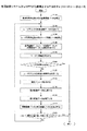
図12は、色調変換システム610又はMFP700が色調補正する手順を示すフローチャート図の一例である。図12において図7と同様のステップの処理は説明を簡略する。
FIG. 12 is an example of a flowchart illustrating a procedure in which the color
画像読み取り部41は、基準印刷物を読み取り、基準画像データを生成する(S110)。
The
ユーザプリンタ200が、原稿画像データを印刷してユーザ印刷物を出力する(S120)。
The
画像読み取り部41が、ユーザ印刷物を読み取り、ユーザ画像データを生成する(S130)。
The
次に、幾何学変換パラメータ推定部42は、基準画像データとユーザ画像データとを原稿画像データに位置合わせする(S140)。
Next, the geometric transformation
次に、色成分値対応付け部44は、ユーザ印刷物を評価する(S150)。そして、ユーザ印刷部が妥当か否かを判定する(S160)。
Next, the color component
次に、いくつかの処理を経て、色調再現特性推定部45がユーザプリンタ200の色調再現特性を推定する(S160)。
Next, through several processes, the color tone reproduction
色調再現特性の推定について、図13のフローチャート図等を用いて詳細に説明する。
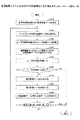
図13は、色調再現特性推定部45がユーザプリンタ200の色調再現特性を推定する手順を示すフローチャート図の一例である。
The estimation of the color tone reproduction characteristic will be described in detail with reference to the flowchart of FIG.
FIG. 13 is an example of a flowchart illustrating a procedure in which the color tone reproduction
まず、画素値対応付け部43は、原稿画像データとユーザ画像データとの同じ位置の画素値を対応付ける(S1621)。すなわち、原稿画像データとユーザ画像データの位置合わせが完了したら、二つの画像データにおいて対応する画素の画素値を取得し、これらを対応付けて画素値対応付けデータを作成する。なお、画像データを幾何学変換して位置合わせを行う場合には、「対応する画素」とは「同じ位置にある画素」である。一方、画像データを幾何学変換しない場合には、座標変換によって同じ座標値となる位置を「同じ位置」とし、その位置に存在する画素を「対応する画素」と見なす。
First, the pixel
画素値を対応付けて記録する方法の例としては、リスト形式で記録する方法や、マトリックス形式で記録する方法がある。原稿画像データとユーザ画像データが両方ともRGB画像で各色成分が256階調であるケースを想定して説明する。 Examples of a method for recording pixel values in association with each other include a method for recording in a list format and a method for recording in a matrix format. Description will be made assuming that both the document image data and the user image data are RGB images and each color component has 256 gradations.
a)リスト形式で記録する方法
色成分値のリストへの記録は次の手順で行う。
a) Method of recording in list format Recording of color component values in a list is performed according to the following procedure.
a-1)リストを3枚用意する
a-2)原稿画像データのある座標を選択する
a-3) a-2で選択された原稿画像データの画素のR成分値と、ユーザ画像データの対応する画素のR成分値とを対応づけてR成分用のリストに追加する
a-4)同様に、G成分値はG成分用のリストに、B成分値はB成分用のリストに、それぞれ追加する
a-5)これを原稿画像データの全ての座標について繰り返す
これらのリストは必要に応じて昇順や降順に並び替えてもよい。
a-1) Prepare 3 lists
a-2) Select the coordinates with the original image data
a-3) The R component value of the pixel of the original image data selected in a-2 and the R component value of the corresponding pixel of the user image data are associated with each other and added to the R component list.
a-4) Similarly, the G component value is added to the G component list, and the B component value is added to the B component list.
a-5) This is repeated for all coordinates of the document image data. These lists may be rearranged in ascending or descending order as necessary.
b) マトリクス形式で記録する方法
色成分値の対応関係のマトリクスへの投票は次の手順で行う。ここでは原稿画像データの値を縦軸に、ユーザ画像データの値を横軸に採るものとする。
b) Method of recording in matrix format Voting for a matrix of correspondence of color component values is performed according to the following procedure. Here, the value of the document image data is taken on the vertical axis, and the value of the user image data is taken on the horizontal axis.
b-1)256行256列のマトリクスを3枚用意する
b-2)原稿画像データのある座標を選択する
b-3) R成分用のマトリクスにおいて、原稿画像データのa-2)で選択された画素のR成分値の行、ユーザ画像データの対応する画素のR成分値の列とが交差する場所に一票投票する
b-4)同様に、G成分値の対応関係をG成分用のマトリクスに、B成分値の対応関係をB成分用のマトリクスに、それぞれ投票する
b-5)これを原稿画像の全ての座標について繰り返す
具体的には、原稿画像データのある座標の画素の画素値がRGBの順に(128, 130, 132)で、ユーザ画像データの対応する画素の画素値が(132, 130, 126)であれば、上記3枚のマトリクスのうちR成分に対応するマトリクスを選び、その128行132列に一票を投じるという具合である。同様に、G成分に対応するマトリクスの130行130列に一票を、B成分に対応するマトリクスの132行126列に一票を、それぞれ投じる。なお、原稿画像データの値とユーザ画像データの値のどちらを縦軸に割り当て、どちらを横軸に割り当てるかは必要に応じて決定すればよい。
b-1) Prepare 3 matrix of 256 rows and 256 columns
b-2) Select the coordinates with the original image data
b-3) In the R component matrix, at the place where the row of the R component value of the pixel selected in a-2) of the original image data and the column of the R component value of the corresponding pixel of the user image data intersect. Vote
b-4) Similarly, the G component value correspondence is voted for the G component matrix, and the B component value correspondence is voted for the B component matrix.
b-5) Repeat this process for all coordinates of the document image. Specifically, the pixel values of the pixels at a certain coordinate in the document image data are in the order of RGB (128, 130, 132), and the corresponding pixels of the user image data. If the pixel value is (132, 130, 126), the matrix corresponding to the R component is selected from the above three matrices, and one vote is cast on the 128 rows and 132 columns. Similarly, one vote is cast on 130 rows and 130 columns of the matrix corresponding to the G component, and one vote is placed on 132 rows and 126 columns of the matrix corresponding to the B component. It should be noted that which of the document image data value and the user image data value is assigned to the vertical axis and which is assigned to the horizontal axis may be determined as necessary.
リスト形式で記録する方法でも、マトリクス形式で記録する方法でも、処理を簡略化するために、原稿画像データの全ての座標について繰り返すのではなく、特定の範囲に限定したり、所定の刻み幅で座標を移動したりしてもよい。 Regardless of whether the method is a list format or a matrix format, the process is not repeated for all the coordinates of the original image data, but is limited to a specific range or at a predetermined step size in order to simplify the process. The coordinates may be moved.
次に、色成分値対応付け部44は、原稿画像データとユーザ画像データで対応する色成分の値を対応付ける (S1622)。すなわち、画素値対応付けデータを用いて、原稿画像データのある色成分値とユーザ画像データのどの色成分値とが対応付くかを求め、色成分値対応付けデータを作成する。
Next, the color component
原稿画像データとユーザ画像データが両方ともRGB画像で各色成分が256階調であるケースを例に説明する。
a) 画素値対応付けデータがリスト形式である場合
画素値対応付けデータがリストとして記録されている場合には、次の手順で行う。
A case where both the original image data and the user image data are RGB images and each color component has 256 gradations will be described as an example.
a) When the pixel value association data is in a list format When the pixel value association data is recorded as a list, the following procedure is used.
a-1)原稿画像データのある色成分のある値を選択する
a-2)a-1)で選択された色成分に対応するリストを取得する
a-3) a-2)で得られたリストから、a-1)で選択された値に対応するレコードを全て取得する
a-4) a-3)で取得された全レコードのユーザ画像データの色成分値を合成する
a-5) a-1)で選択された原稿画像データの色成分値と、a-4)で合成された値とを対応付けて色成分値対応付けデータとして記録する。
a-1) Select a value with a color component in the original image data
a-2) Get a list corresponding to the color component selected in a-1)
a-3) Get all records corresponding to the value selected in a-1) from the list obtained in a-2)
a-4) Synthesize color component values of user image data of all records obtained in a-3)
a-5) The color component value of the document image data selected in a-1) is associated with the value synthesized in a-4) and recorded as color component value association data.
a-6)これを各色成分の各値について繰り返す
ステップa-3)において取得されたレコードが一つのみであれば、色成分値対応付け部44はa-4)において、取得されたレコードの値をそのまま利用する。a-3)において取得されたレコードが複数あれば、ユーザ画像データ側の値を合成して一つの値にした上で利用する。複数の値を合成する方法の例としては、平均値を採用する方法、最頻値を採用する方法、中央値を採用する方法が挙げられる。
b) 画素値対応付けデータがマトリクス形式である場合
画素値対応付けデータがマトリクスとして記録されている場合には、次の手順で行う。
a-6) Repeat this for each value of each color component If there is only one record acquired in step a-3), the color component
b) When the pixel value association data is in a matrix format When the pixel value association data is recorded as a matrix, the following procedure is used.
b-1)原稿画像データのある色成分のある値を選択する
b-2) b-1)で選択された色成分に対応するマトリクスを取得する
b-3) b-2)で得られたマトリクスから、b-1で選択された値に対応する行を抽出する
b-4) b-3)で抽出された行において投票されている列の値を合成する
b-5) 選択された原稿画像データの色成分値と、b-4)で合成された値とを対応付けて色成分値対応付けデータとして記録する
b-6)これを各色成分の各値について繰り返す
b-4)において抽出された行で投票が一つの列のみに存在する場合には、その列番号を合成された値として採用する。b-4)において投票が複数の列に存在する場合には、合成して一つの値にした上で利用する。複数の値を合成する方法の例は、a)と同様である。但し、投票数は列番号の出現回数として使用する。
b-1) Select a value with a certain color component in the original image data
b-2) Get the matrix corresponding to the color component selected in b-1)
b-3) Extract the row corresponding to the value selected in b-1 from the matrix obtained in b-2)
b-4) Combining the values of columns voted in the row extracted in b-3)
b-5) The color component value of the selected document image data is associated with the value synthesized in b-4) and recorded as color component value association data
b-6) Repeat this for each value of each color component
If a vote is found in only one column in the row extracted in b-4), that column number is adopted as the synthesized value. If the votes in b-4) exist in multiple columns, they are combined and used as one value. An example of a method of combining a plurality of values is the same as in a). However, the number of votes is used as the number of appearances of the column number.
仮に原稿画像データにおいて使用されていない色成分値が存在した場合には、その旨が判別できるように記録しておくことが望ましい。(ここで記録した情報は次ステップで利用することができる)
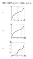
次に、色調再現特性推定部45は色調変換特性を推定する (S1623)。色成分値対応付けデータのデータ系列を用いて色調変換特性を推定する。色調変換特性は色成分値対応付けデータをそのまま利用してもよいし、色成分値対応付けデータを加工して利用してもよい。データを加工する目的は、極端な値の変動の抑制や、特性曲線の安定性向上である。
If there is a color component value that is not used in the document image data, it is desirable to record it so that it can be determined. (The information recorded here can be used in the next step)
Next, the color tone reproduction
色成分値対応付けデータを加工して利用する方法の例としては、次のようなものが挙げられる。
a) 移動平均をかける
データ系列において注目するデータとその前後のデータとを加重平均する方法である。前後のデータの参照範囲はデータ系列の値に対する滑らかさの要求に応じて決定すればよい。より滑らかにするためには参照範囲を広く取る必要がある。また、加重平均に用いる重みは全てのデータに対して一定であってもよいし、注目するデータからの距離に反比例させてもよい。
Examples of methods for processing and using the color component value association data include the following.
a) A weighted average of the data of interest in the data series to which the moving average is applied and the data before and after it. The reference range of the preceding and following data may be determined according to the smoothness requirement for the data series values. In order to make it smoother, it is necessary to take a wide reference range. The weight used for the weighted average may be constant for all data, or may be inversely proportional to the distance from the data of interest.
移動平均をかける前に、データ系列を昇順か降順に並び替える必要がある。また、原稿画像データにおいて使用されていない色成分値が存在すると、並べ替えた際にデータ系列の要素が欠落するが、この欠落した要素が他のデータに影響を与えないように加重平均から除外する必要がある。要素が欠落しているか否かは、データが連続しているかどうかを確認したり、前ステップで記録した使用されていない色成分値の情報を利用したりすることにより把握できる。
b) 直線や曲線で近似する
データ系列を一次関数、二次関数、スプライン関数、指数関数などを用いて近似する方法である。
c) 階調数を削減した上で直線や曲線で補間や近似する
色成分値対応付けデータのデータ系列の階調数を削減する方法としては、次のような例が考えられる。
Before applying the moving average, it is necessary to rearrange the data series in ascending or descending order. In addition, if there are color component values that are not used in the original image data, the elements of the data series are missing when rearranged, but this missing element is excluded from the weighted average so that it does not affect other data. There is a need to. Whether or not an element is missing can be grasped by checking whether data is continuous or by using information on unused color component values recorded in the previous step.
b) A method of approximating a data series approximated by a straight line or curve using a linear function, a quadratic function, a spline function, an exponential function, or the like.
c) As a method of reducing the number of gradations of the data series of the color component value association data to be interpolated or approximated by a straight line or curve after reducing the number of gradations, the following example can be considered.
ア) 階調の値域を等間隔で分割し、これにより統合される各階調のデータを合成する
分割数や分割幅は予め決定しておいてもよいし、動的に決定してもよい。
A) The gradation range may be divided at equal intervals, and the number of divisions and the division width for synthesizing the data of each gradation to be integrated may be determined in advance or may be determined dynamically.
ア−1)分割数や分割幅を予め決定するケース
図14(a)は、分割数や分割幅を予め決定するケースを説明する図の一例である。図13(a)では、0〜255までの256階調を、予め与えられた分割数4で等間隔に分割した例である。0〜63、64〜127、128〜191、192〜255という4つの領域に分割することにより、それぞれ64階調が1つの階調に削減される(1つの変換特性に統合される)ことになる。なお、分割数でなく分割幅を与えても同じ効果が得られる。
A-1) Case where the number of divisions and division width are determined in advance FIG. 14A is an example of a diagram illustrating a case where the number of divisions and division width are determined in advance. FIG. 13A shows an example in which 256 gradations from 0 to 255 are divided at equal intervals by a
ア−2)分割数や分割幅を動的に決定するケース
等間隔に分割するケースで、分割数や分割幅を動的に決定する方法の例としては、画素数に比例させる方法がある。例えば、画素数を経験的に決められた所定の数で割った値を分割数とする、などの決定方法が考えられる。
A-2) Case of dynamically determining the number of divisions and the division width As an example of a method of dynamically determining the number of divisions and the division width in the case of dividing at equal intervals, there is a method in which the number of divisions and the division width are proportional to the number of pixels. For example, a determination method is conceivable in which a value obtained by dividing the number of pixels by a predetermined number determined empirically is used as the division number.
イ−1) 階調の値域を不等間隔で分割し、これにより統合される各階調のデータを合成する
各階調に対応する画素値対応付けデータにおける投票数を用いて、合成される階調の得票数が、所定の数となるように分割幅を適応的に決定する。
A-1) Dividing the range of gradations at unequal intervals, and synthesizing the data of each gradation integrated thereby, the gradation to be synthesized using the number of votes in the pixel value association data corresponding to each gradation The division width is adaptively determined so that the number of votes obtained becomes a predetermined number.
図14(b)は、0〜255までの256階調を不等間隔で4分割した例である。0から(a-1)、aから(b-1)、bから(c-1)、cから255という四つの領域に分割されるが、それぞれ1つの階調に削減される。なお、階調a、b、cをその階調を挟むどちらの階調に統合するかは任意である。 FIG. 14B is an example in which 256 gradations from 0 to 255 are divided into four at unequal intervals. It is divided into four areas from 0 to (a-1), a to (b-1), b to (c-1), and c to 255, each reduced to one gradation. It should be noted that the gradations a, b, and c are arbitrarily combined with which gradation sandwiching the gradations.
不等間隔で分割する際に、統合する階調数を決定する方法の例としては、各階調に属する画素数の累積頻度を等間隔で分割する方法や、各階調に属する画素数の頻度のヒストグラムを用いる方法が挙げられる。 Examples of a method of determining the number of gradations to be integrated when dividing at unequal intervals include a method of dividing the cumulative frequency of the number of pixels belonging to each gradation at equal intervals, and a frequency of the number of pixels belonging to each gradation. A method using a histogram is mentioned.
i)各階調に属する画素数の累積頻度を用いる方法
各階調に属する画素数の累積頻度を等間隔で区切り、区切り位置に対応する階調で分割する方法である。
i) Method using the cumulative frequency of the number of pixels belonging to each gradation This is a method of dividing the cumulative frequency of the number of pixels belonging to each gradation at equal intervals and dividing by the gradation corresponding to the separation position.
図14(c)は0〜255までの256階調を不等間隔で4分割する例である。縦軸の累積頻度の最大値を1.0としたときに、区切り位置として0.25、0.50、0.75となる階調を求めることにより、分割位置を決定する。この例では、累積頻度が0.25となる階調a、0.50となる階調b、0.75となる階調cが求まり、上述した四つの領域が決定できる。このような区切り方によれば、各区分でデータ数が同じなので各変換特性が与えられる画素数を等しくできる。 FIG. 14C shows an example in which 256 gradations from 0 to 255 are divided into four at unequal intervals. When the maximum value of the cumulative frequency on the vertical axis is 1.0, the division position is determined by obtaining gradations that are 0.25, 0.50, and 0.75 as the separation positions. In this example, the gradation a with an accumulated frequency of 0.25, the gradation b with 0.50, and the gradation c with 0.75 are obtained, and the above-described four regions can be determined. According to such a division method, since the number of data is the same in each section, the number of pixels to which each conversion characteristic is given can be made equal.
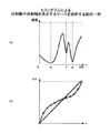
ii)各階調に属する画素数の頻度分布を用いる方法
図15(a)は、各階調に属する画素数の頻度のヒストグラムを作成し、極小となる階調e、f、gで分割する方法である。このような区切り方によれば、変換特性が切り替わる画素数を小さくできる。
ii) Method using frequency distribution of the number of pixels belonging to each gradation FIG. 15A is a method of creating a histogram of the frequency of the number of pixels belonging to each gradation and dividing it by the minimum gradations e, f, and g. is there. According to such a division method, the number of pixels whose conversion characteristics are switched can be reduced.
以上のようにして、階調数を削減したら、元の階調数まで戻るように、統合された階調の間を補間したり、統合されたデータを元に直線や曲線で近似したりする。 When the number of gradations is reduced as described above, interpolation is performed between the integrated gradations so that the original number of gradations is restored, or approximation with a straight line or curve based on the integrated data is performed. .
図15(b)は、削減された階調数を直線近似や曲線近似により元の階調数まで戻す例を示す。丸が統合されたデータ、実線の直線が直線近似の例、実線の曲線が曲線近似の例である。近似に利用する関数は、統合されたデータの傾向に合わせて選択することが望ましい。このように補間したり、直線や曲線で近似したりすることで、推定される変換特性から少ない画素数に起因する特異的な変換を除外できる。 FIG. 15B shows an example in which the reduced number of gradations is returned to the original number of gradations by linear approximation or curve approximation. Data in which circles are integrated, a solid line is an example of linear approximation, and a solid line is an example of curved approximation. It is desirable to select the function used for approximation according to the trend of the integrated data. By interpolating in this way or approximating with a straight line or curve, it is possible to exclude specific conversion caused by a small number of pixels from the estimated conversion characteristics.
図12に戻り、補正パラメータ決定部64は、ユーザプリンタ200の色調再現特性から補正パラメータを求める(S164)。補正パラメータは、差分画像データ上のある値を原稿画像データに反映する際の係数と換言することもできるし、その係数を導出するための材料と表現することもできる。
Returning to FIG. 12, the correction
差分画像データを原稿画像データにそのまま反映してもよいが、補正処理をかけたほうがよい。この理由について説明する。差分画像データは基準画像データとユーザ画像データとの差分であり、これらの画像データは原稿画像データに各出力画像機器の色調再現特性が重畳されたものである。したがって、補正により原稿画像データ上に生じた画素値の差が、基準画像データとユーザ画像データ上での二つの値の差と同じ大きさでも、その意味が異なってしまう。 The difference image data may be reflected on the document image data as it is, but it is better to apply a correction process. The reason for this will be described. The difference image data is a difference between the reference image data and the user image data. These image data are obtained by superimposing the color tone reproduction characteristics of each output image device on the document image data. Therefore, even if the difference between the pixel values generated on the original image data due to the correction is the same as the difference between the two values on the reference image data and the user image data, the meaning is different.
このため、本実施例では、差分画像データに対して補正パラメータによる補正処理を行い、原稿画像データ上での意味と等価に変換する必要がある。 For this reason, in this embodiment, it is necessary to perform a correction process using the correction parameter on the difference image data and convert it to the equivalent of the meaning on the document image data.
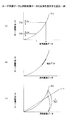
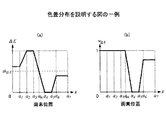
図16は、ユーザ画像データと原稿画像データの関係を説明する図の一例である。図のP(x)は、S162で求められた色調再現特性である。すなわち、原稿画像データの画素値aはユーザ画像データのP(a)に対応付けられる。一般に、色調再現特性は線形ではないため、ユーザ画像データ上のある画素値P(a)近傍の差Δaと別の画素値P(b)近傍での差Δbとでは、原稿画像データ上の意味合いが異なる。図の例だと、差Δaは色調再現特性により差Δbよりも強調されている。このため、差分画像データに行う補正処理は、その元となる基準画像データやユーザ画像データ上での画素値に依存したものである必要がある。 FIG. 16 is an example of a diagram illustrating the relationship between user image data and document image data. P (x) in the figure is the color tone reproduction characteristic obtained in S162. That is, the pixel value a of the document image data is associated with P (a) of the user image data. In general, since the color tone reproduction characteristic is not linear, the difference Δa in the vicinity of a certain pixel value P (a) on the user image data and the difference Δb in the vicinity of another pixel value P (b) have implications on the original image data. Is different. In the example of the figure, the difference Δa is emphasized more than the difference Δb due to the color tone reproduction characteristics. For this reason, the correction processing performed on the difference image data needs to depend on the pixel values on the reference image data or user image data as the source.
原稿画像データのある画素の画素値をx、ユーザ画像データの対応する画素の画素値をyとすると、その画素値に作用させる補正パラメータα(x)を求める方法の例として、以下のようなものが挙げられる。
a)傾きの逆数を用いる方法
色調再現特性関数y=P(x)の傾きP'(x)を全ての階調について求め、その傾きの逆数を用いる方法である。図16(b)は傾きを模式的に説明する図の一例である。色調再現特性関数の傾きは、原稿画像データにおけるある画素値近傍での値の微小な変動(変化量)が、ユーザ画像データにおいてどのように反映されるかを表す(反映される変化量)。補正処理では、差分画像データを原稿画像データに反映するために補正を行うため、ユーザ画像データにおける微小な変動が、原稿画像データにおいてどの程度の変動に相当するかを知る必要がある。これは上記傾きの逆数を取ることにより知ることができる。したがって、この方法での補正パラメータα(x)は次式で表せる。
As an example of a method for obtaining a correction parameter α (x) to be applied to a pixel value of a pixel in the document image data where x is a pixel value and y is a pixel value of a corresponding pixel in the user image data, the following Things.
a) Method Using Reciprocal of Inclination In this method, the inclination P ′ (x) of the tone reproduction characteristic function y = P (x) is obtained for all gradations, and the inverse of the inclination is used. FIG. 16B is an example of a diagram for schematically explaining the inclination. The inclination of the color tone reproduction characteristic function represents how a minute variation (change amount) in the vicinity of a certain pixel value in the document image data is reflected in the user image data (change amount reflected). In the correction process, correction is performed in order to reflect the difference image data in the document image data. Therefore, it is necessary to know how much the minute variation in the user image data corresponds to the variation in the document image data. This can be known by taking the reciprocal of the slope. Therefore, the correction parameter α (x) in this method can be expressed by the following equation.
原稿画像データのある色をユーザ画像データで正確に再現できると、色調再現特性関数は直線y=xと表現できる。図16(c)は直線y=xとP(x)を模式的に説明する図の一例である。実際の色調再現特性関数P(x)とこの直線との値の比を求めることにより、原稿画像データのある画素値がユーザ画像データにおいて、どの程度値として変倍されているかを知ることができる。差分画像データもこの様にして変倍されたと見なせば、この比の逆数を乗算することにより原稿画像データに反映すべき値を知ることができる。したがって、この方法での補正パラメータα(x)は次式で表せる。
次に、差分検出部61は、差分画像データを生成する(S170)。差分画像データの求め方は実施例1と同様である。
Next, the
次に、補正処理部62は、ステップS164で得られた補正パラメータを用いて差分画像データを補正する(S180)。例えば、ユーザ画像データのある画素が画素値aを持ち、かつその画素に対応する差分画像データの値がcであった時、補正された差分画像データの対応する画素の値c'は、次式のように表せる。
Next, the
次に、画像合成部63は、原稿画像データと補正画像データとを合成する (S190)。
色調変換システム610は、色調変換の回数が所定の回数に達したら(S200のYes)、図12の処理を終了する。
Next, the
When the number of color tone conversions reaches a predetermined number (Yes in S200), the color
色調変換の回数が所定の回数に達していないため、継続する場合(S200のNo)、補正済みの原稿画像データを入力としてユーザプリンタ200から印刷し(S110)、処理を継続する。次のループで用いる原稿画像データは全て補正済みものである。
If the number of color tone conversions has not reached the predetermined number and continues (No in S200), the corrected original image data is printed from the
なお、上記では、ユーザプリンタ200の色調再現特性を元にして補正パラメータを導出しているが、基準プリンタ400の色調再現特性も用いて補正パラメータを導出してもよい。その方法の一例を説明する。
In the above description, the correction parameter is derived based on the color tone reproduction characteristic of the
S110〜S162までの手順は図12と同じである。S162においてユーザプリンタ200の色調再現特性P2(x)を推定後、同じ手続きで基準プリンタ400の色調再現特性P1(x)の推定を行う。
The procedure from S110 to S162 is the same as that in FIG. After estimating the color tone reproduction characteristic P 2 (x) of the
続いて、補正パラメータの推定において、基準プリンタ400の色調再現特性P1(x)とユーザプリンタ200の色調再現特性P2(x)との差Pd(x)を例えば次式で求める。 Subsequently, in the estimation of the correction parameters, determining the difference P d (x) of the color tone reproduction property P 1 of the reference printer 400 (x) and the tone reproduction characteristic P 2 user printer 200 (x) for example, by the following equation.
つまり、基準画像データとユーザ画像データとの差は、各画像出力機器の色調再現特性の差によって生じたと考え、画像データの差として検出された値に対して、色調再現特性の差の逆変換をかけることにより、原稿画像データ上での差を求める方法である。 In other words, the difference between the reference image data and the user image data is considered to be caused by the difference in color reproduction characteristics of each image output device, and the inverse conversion of the difference in color reproduction characteristics from the value detected as the difference in image data. This is a method of obtaining the difference on the document image data by applying.
本実施例によれば、実施例1の効果に加え、差分画像データの補正パラメータを色調再現特性から動的に生成することで、精度良く差分画像データを補正することができる。 According to the present embodiment, in addition to the effects of the first embodiment, the differential image data can be corrected with high accuracy by dynamically generating the correction parameters of the differential image data from the color tone reproduction characteristics.
本実施例は、実施例1において原稿画像データと補正画像データとを合成する際に、重み付けをして合成する色調変換システム610について説明する。こうすることで、色調変換による、原稿画像データの画素値の変動を抑制することができる。
In the present embodiment, a color
図17は、本実施例の色調変換システム610又はMFP700の機能ブロック図の一例である。図17において図6と同一部の説明は省略する。本実施例の色調変換システム610又はMFP700は、画素対応付け部51、色差取得部52、色空間距離取得部53、及び、合成重み決定部54、を有する。
FIG. 17 is an example of a functional block diagram of the color
画素対応付け部51は、幾何学変換パラメータを用いて、基準画像データとユーザ画像データの対応する画素を検出し、それらを対応付けて画素対応付けデータを作成する。 The pixel association unit 51 detects corresponding pixels of the reference image data and the user image data using the geometric transformation parameter, and associates them to create pixel association data.
色差取得部52は、画素対応付けデータを用いて得られる、基準画像データとユーザ画像データの対応する画素の色差を求め色差データを作成する。
The color
色空間距離取得部53は、無彩色からの原稿画像データの各色の距離を求め距離データを作成する。無彩色からの、基準画像データ又はユーザ画像データの各色の距離を求めてもよい。基準画像データ又はユーザ画像データでも距離データには同様の傾向があると考えられるためである。
The color space
合成重み決定部54は、色差データと距離データとから画像データの合成に用いる合成重みを決定する。
The combination
図18は、色調変換システム610又はMFP700が色調補正する手順を示すフローチャート図の一例である。図18において図7と同様のステップの処理は説明を簡略する。
FIG. 18 is an example of a flowchart illustrating a procedure in which the color
画像読み取り部41は、基準印刷物を読み取り、基準画像データを生成する(S110)。
The
ユーザプリンタ200が、原稿画像データを印刷してユーザ印刷物を出力する(S120)。
The
画像読み取り部41が、ユーザ印刷物を読み取り、ユーザ画像データを生成する(S130)。
The
次に、幾何学変換パラメータ推定部42は、基準画像データとユーザ画像データとを原稿画像データに位置合わせする(S140)。すなわち、原稿画像データを基準とし、基準画像データとユーザ画像データの幾何学変換パラメータをそれぞれ求め、幾何学変換パラメータを用いて位置合わせを行う。
Next, the geometric transformation
また、本実施例では、幾何学変換パラメータが推定されると、画素対応付け部51が、幾何学変換パラメータを用いて、原稿画像データの画素と対応する位置の基準画像データ又はユーザ画像データの画素を検出し、それらを対応付けて画素対応付けデータを作成する。 In this embodiment, when the geometric conversion parameter is estimated, the pixel association unit 51 uses the geometric conversion parameter to store the reference image data or user image data at the position corresponding to the pixel of the document image data. Pixels are detected and associated with each other to create pixel association data.
基準画像データとユーザ画像データに幾何学変換を施せば、基準画像データとユーザ画像データは原稿画像データと画像の位置がほぼ一致している。したがって、基準画像データとユーザ画像データの同じ座標の画素は互いに対応していると考えられる。画素対応付け部51はこのように2つの幾何学変換パラメータを求めて基準画像データとユーザ画像データの画素を対応づける。 If geometric conversion is applied to the reference image data and the user image data, the reference image data and the user image data are substantially in the same position as the document image data. Therefore, it is considered that pixels having the same coordinates in the reference image data and the user image data correspond to each other. In this way, the pixel association unit 51 obtains two geometric transformation parameters and associates the pixels of the reference image data with the user image data.
また、ステップS140では、原稿画像データと基準画像データ、及び、原稿画像データとユーザ画像データの幾何学変換パラメータを推定したが、基準画像データとユーザ画像データの間の幾何学変換パラメータを求めてもよい。すなわち、基準画像データとユーザ画像データの画像の位置を一致させるための幾何学変換パラメータを求め、いずれかに幾何学変換パラメータによる変換を施すことで、基準画像データとユーザ画像データの画像の位置をほぼ一致させることができる。 In step S140, the original image data and the reference image data, and the geometric conversion parameters of the original image data and the user image data are estimated, but the geometric conversion parameters between the reference image data and the user image data are obtained. Also good. That is, by obtaining a geometric transformation parameter for matching the position of the image of the reference image data and the user image data, and performing the transformation by the geometric transformation parameter to either, the position of the image of the reference image data and the user image data Can be substantially matched.
なお、幾何学変換は必須ではなく、原稿画像データと基準画像データ(又はユーザ画像データ)において同じ位置の画素を特定するため、幾何学変換パラメータを用いて座標変換を行い、同じ位置か否かを判断することによって代替してもよい。後者を換言すれば、各画像の原点を基準とする座標系では異なる座標値を保持していても、幾何学変換の結果、同じ座標値となる画素を「同じ位置の画素」と見なすことになる。 Note that geometric conversion is not essential, and in order to identify the pixel at the same position in the document image data and the reference image data (or user image data), coordinate conversion is performed using the geometric conversion parameter to determine whether the positions are the same. It may be substituted by judging. In other words, even if the coordinate system based on the origin of each image holds different coordinate values, the pixels with the same coordinate value as a result of geometric transformation are regarded as “pixels at the same position”. Become.
原稿画像データを出力して得られた印刷物には画像の周囲に余白が存在するケースが存在する。この様なケースでは、幾何学変換の変位量に余白部分の高さや幅が含まれるため余白部分を参照することはないが、出力画像データにおいて余白部分を排除するように必要な領域を切り出し、各画像における原点の位置を一致させてもよい。 There are cases where margins exist around the printed material obtained by outputting the document image data. In such a case, since the height and width of the margin part are included in the displacement amount of the geometric transformation, the margin part is not referred to, but a necessary area is cut out in the output image data so as to exclude the margin part, You may make the position of the origin in each image correspond.
次に、色差取得部52は、ユーザ印刷物を評価する(S150)。そして、ユーザ印刷部が妥当か否かを判定する(S160)。
Next, the color
妥当な場合(S160のYes)、次に、色差取得部52は色差データを取得する(S165)。色差取得部52は、基準画像データとユーザ画像データとの色差を画素ごとに求め色差データとする。したがって、色差データは画像データと同じ大きさのマップとして管理され、基準画像データとユーザ画像データの座標と色差のマップの座標とは対応付く。
If valid (Yes in S160), the color
色差の導出方法は実施例1のユーザ印刷物の品質評価にて説明したとおりである。なお、ユーザ印刷物の評価において色差を用いた場合には、そこで求められた画素ごとの色差を利用して、本ステップを省略してもよい。
色差データは以下のように加工してもよい。
a) マップを移動平均により平滑化する
b) マップを低解像度化する(複数の画素の色差を合成した値で代替する)
c) マップから基準画像データやユーザ画像データにおける輪郭部分に対応する領域を除去する
画素ごとに色差を求めると色差データにノイズが乗るケースが存在するため、マップの平滑化や低解像度化をすることが望ましい。また、マップの輪郭部分を除去する場合には、マップが不連続とならないように除去した部分を適宜補間することが望ましい。補間方法には従来技術を用いればよく、例えば線形補間やキュービック補間などのほか、平滑化処理を用いてもよい。
The method for deriving the color difference is as described in the quality evaluation of the user printed matter in the first embodiment. In addition, when the color difference is used in the evaluation of the user printed matter, this step may be omitted by using the color difference for each pixel obtained there.
The color difference data may be processed as follows.
a) Smooth map with moving average
b) Lower the map resolution (substitute with the synthesized color difference of multiple pixels)
c) If the color difference is calculated for each pixel from which the area corresponding to the contour portion in the reference image data or user image data is removed from the map, noise may be added to the color difference data. It is desirable. When removing the contour portion of the map, it is desirable to appropriately interpolate the removed portion so that the map does not become discontinuous. Conventional techniques may be used for the interpolation method. For example, smoothing processing may be used in addition to linear interpolation and cubic interpolation.
次に、色空間距離取得部53は距離データを求める(S166)。すなわち、原稿画像データにおいて利用されている各色の、無彩色からの距離を求め距離データとする。距離データは色差データと同様に画像データと同じ大きさのマップとして管理してもよいし、色と距離を対応付けたリストとして管理してもよい。距離データを求める手順の一例を以下に示す。
(1)原稿画像データの色空間をL*a*b*色空間に変換する
(2)原稿画像データから色を1つ選び無彩色からの距離d* abを求める
(3)これを原稿画像データの全ての色について繰り返す
距離d* abの定義の例としては、次式が挙げられる。
Next, the color space
(1) Convert the color space of the original image data to L * a * b * color space (2) Select one color from the original image data and obtain the distance d * ab from the achromatic color (3) This is the original image The following equation is an example of the definition of the distance d * ab that repeats for all colors of the data.
次に、合成重み決定部54は、合成重みデータを決定する(S 167)。合成重み決定部54は、色差データと距離データとを用いて合成重みデータを決定する。合成重みデータを求める手順の一例を以下に示す。ここでは色差データと距離データとはマップとして管理されることを前提として説明する。
(1)色差データを色差の閾値thΔEで割った後、最大値を1で飽和させ(1以上の重みを全て1とみなす)、色差重みデータを作成する
(2)距離データを距離の閾値thdで割った後、最大値を1で飽和させ(1以上の重みを全て1とみなす)、距離重みデータを作成する
(3)色差データのある座標における値と、距離データの対応する座標における値とを乗算し、重みを算出する
(4)(3)を全ての座標について繰り返す
上記色差の閾値thΔEや距離の閾値thdは、予めユーザにより設定された値を用いてもよいし、色差データや距離データの平均値や中央値など何らかの統計処理を施した値を用いてもよい。特に距離の閾値thdは、L*a*b*色空間におけるa*成分値とb*成分値の取りうる最大値a* maxおよびb* maxを用いて次式で求めてもよい。
Next, the composite
(1) After dividing the color difference data by the color difference threshold th ΔE , saturate the maximum value with 1 (assuming all weights of 1 or more are considered as 1), and create color difference weight data (2) Distance data is the distance threshold After dividing by th d , saturate the maximum value with 1 (assuming all weights greater than or equal to 1) and create distance weight data. (3) Values at coordinates with color difference data and corresponding coordinates of distance data (4) and (3) in which weights are calculated for all coordinates by multiplying by the value at, and the color difference threshold th ΔE and the distance threshold th d may be values set in advance by the user. Alternatively, a value subjected to some statistical processing such as an average value or median value of color difference data and distance data may be used. In particular, the distance threshold th d may be obtained by the following equation using the a * component value in the L * a * b * color space and the maximum values a * max and b * max that the b * component value can take.
図19(a)は距離の最大値を閾値とした場合の距離重みデータの一例を示す。例えば、距離の閾値thdを上式により求めるケースでは、距離重みデータwdが距離d* abが0から最大値d* maxまで連続的に変化する。最大値d* maxは1である。 FIG. 19A shows an example of distance weight data when the maximum value of distance is used as a threshold value. For example, in the case of obtaining the above equation the threshold th d distance, distance weight data w d is the distance d * ab continuously changes from 0 to a maximum value d * max. The maximum value d * max is 1.
図19(b)は、距離の閾値thdとしてd* maxよりも小さい値を採用した場合の距離重みデータの一例を示す。図示するように、距離重みデータwdが距離d* abが0からthdまで連続的に変化し、それ以降は1で飽和する。 FIG. 19B shows an example of distance weight data when a value smaller than d * max is adopted as the distance threshold th d . As shown in the figure, the distance weight data w d continuously changes from 0 to th d, and the distance d * ab is saturated at 1 thereafter.
また、色差重みデータや距離重みデータは、図19(a)(b)に例示したような線形的な変化だけでなく、所定の関数を用いて非線形に変化させてもよい。
図19(c)(d)は非線形の関数により求められた距離重みデータ又は色差重みデータの一例を示す。関数の例としては、二次関数や指数関数、逆関数などが挙げられる。また、関数だけでなくルック・アップ・テーブルのように予め決定された情報を用いて色差や距離を重みデータに変換してもよい。
Further, the color difference weight data and the distance weight data may be changed not only linearly as illustrated in FIGS. 19A and 19B but also nonlinearly using a predetermined function.
FIGS. 19C and 19D show examples of distance weight data or color difference weight data obtained by a non-linear function. Examples of functions include quadratic functions, exponential functions, and inverse functions. Further, not only functions but also information determined in advance such as a look-up table may be used to convert color differences and distances into weight data.
図20(a)は色差分布の一例を、図20(b)は色差重みデータの一例をそれぞれ示す。ここでan(nは0以上の整数)はマップのx方向又はy方向の位置を示す。ここでは色差重みデータは、合成時に補正画像データにかかる重みとして説明する。まず、補足図20(a)がある色差データの一部であったとする。位置に応じて色差の値が変化しており、x=a4からx=a5までは色差がゼロである。 20A shows an example of the color difference distribution, and FIG. 20B shows an example of the color difference weight data. Here, an (n is an integer of 0 or more) indicates the position in the x direction or y direction of the map. Here, the color difference weight data will be described as the weight applied to the corrected image data at the time of synthesis. First, it is assumed that supplementary FIG. 20A is a part of certain color difference data. The value of the color difference changes according to the position, and the color difference is zero from x = a 4 to x = a 5 .
これに対し図20(b)の色差重みデータは、色差データにおいて値が色差の閾値thΔEより大きい範囲(x=0からx=ath)では1で飽和しており、色差がゼロであるx=a4からx=a5までは重みはゼロとなっている。それらを除く範囲では、色差データの増減に合わせて重みも変動している。 On the other hand, the color difference weight data in FIG. 20B is saturated at 1 in the range (x = 0 to x = a th ) where the value is larger than the color difference threshold th ΔE in the color difference data, and the color difference is zero. From x = a 4 to x = a 5 , the weight is zero. In the range excluding them, the weight also fluctuates as the color difference data increases or decreases.
なお、図20(b)では色差データや色差重みデータの変動を線形に表現しているが、変動は非線形であってもよいし、不連続な箇所が存在してもよい。また、図の都合上一次元で図示しているが、二次元の分布も同様に色差データに応じて色差重みデータは変動する。更に、ここでは色差データを前提として説明したが、色空間の距離についてもほぼ同様であり、色差を距離と読み替えればよい。 In FIG. 20B, the variation of the color difference data and the color difference weight data is expressed linearly, but the variation may be non-linear or there may be discontinuous portions. Further, although it is shown in one dimension for convenience of illustration, the color difference weight data also varies in accordance with the color difference data in the two-dimensional distribution. Furthermore, although the description is based on the assumption of color difference data here, the distance in the color space is almost the same, and the color difference may be read as the distance.
合成重み決定部54は、例えば以下のようにして合成重みWTを求める。ある画素又は画素群の色差重み付けをWc(0≦Wc≦1)、距離重みをWd(0≦Wd≦1)、とする。
WT=Wc・Wd
なお、色差重みのみ又は距離重みのみを使用する場合は、それぞれ以下のようになる。
WT=Wc
WT=Wd
距離重みが、画素又は画素群毎に求められていない場合、着目している原稿画像データの画素又は画素群の色に対応づけられた距離重みを用いる。合成重み決定部54は、補正画像データと同様に、画像データと同じ大きさのマップとして管理される。
The combining
W T = Wc · Wd
In addition, when only the color difference weight or only the distance weight is used, it is as follows.
W T = Wc
W T = Wd
If the distance weight is not obtained for each pixel or pixel group, the distance weight associated with the pixel or pixel group color of the document image data of interest is used. Similar to the corrected image data, the composite
次に、差分検出部61は差分画像データを生成する(S170)。
Next, the
また、補正処理部62は差分画像データを補正する(S180)。補正の方法は実施例1又は実施例2のいずれの方法でもよい。
The
次に、画像データ合成部は、原稿画像データと補正画像データとを合成する (S190)。原稿画像データと補正画像データとを合成して補正済み原稿画像データを生成する手順を以下に示す。
(1)原稿画像データからある座標の画素値を取得する
(2)補正画像データから対応する座標の画素値を取得する
(3)重みデータから対応する座標の重みを取得する
(4)得られた二つの画素値を、上記重みを用いて加重平均し、合成後の画素値を決定する
(5)合成後の画素値を用いて原稿画像データの該当画素を更新する
(6)1)から5)を全ての座標について繰り返す
合成後の画素値GTは、例えば以下のようにして求める。ここである画素又は画素群の色差重み付けをWc(0≦Wc≦1)、距離重みをWd(0≦Wd≦1)、原稿画像データの色をO、補正画像データの色をM、とする。
GT=WT・M+(1−WT)・O
なお、色差重みのみ又は距離重みのみを使用する場合は、それぞれ以下のようになる。
GT=Wc・M+(1−Wc)・O
GT=Wd・M+(1−Wd)・O
上記手順では原稿画像データを補正済み原稿画像データを生成により更新しているが、補正済み原稿画像データを新しい画像データとして作成してもよい。
Next, the image data synthesis unit synthesizes the document image data and the corrected image data (S190). A procedure for generating corrected document image data by combining document image data and corrected image data is shown below.
(1) A pixel value at a certain coordinate is acquired from the original image data. (2) A pixel value at a corresponding coordinate is acquired from the corrected image data. (3) A corresponding coordinate weight is acquired from the weight data. The two pixel values are weighted and averaged using the above weights, and the combined pixel value is determined. (5) The corresponding pixel of the document image data is updated using the combined pixel value. (6) From 1) pixel value G T after synthesis repeating 5) for all the coordinates, for example obtained in the following manner. Here, the color difference weighting of the pixel or pixel group is Wc (0 ≦ Wc ≦ 1), the distance weight is Wd (0 ≦ Wd ≦ 1), the color of the original image data is O, and the color of the corrected image data is M. .
G T = W T · M + (1−W T ) · O
In addition, when only the color difference weight or only the distance weight is used, it is as follows.
G T = Wc · M + (1−Wc) · O
G T = Wd · M + (1−Wd) · O
In the above procedure, the document image data is updated by generating corrected document image data. However, the corrected document image data may be created as new image data.
原稿画像データと補正画像データとを合成する際に上述の重みを用いることにより、以下のような効果が期待できる。
a)基準画像データとユーザ画像データとで元々色が一致している箇所を維持することができる
差分画像データに一括で補正処理をかけてしまうと、基準画像データとユーザ画像データとで本来色が一致していたはずの箇所の色も変化してしまい、全体として色の一致度が改善しても、所定の箇所で色の一致度が低下してしまう。
The following effects can be expected by using the above-mentioned weights when combining the original image data and the corrected image data.
a) It is possible to maintain a portion where the reference image data and the user image data originally have the same color. If correction processing is applied to the difference image data in a batch, the original color is determined between the reference image data and the user image data. As a result, the color of the portion that should have matched also changes, and even if the color matching degree is improved as a whole, the color matching degree is lowered at a predetermined portion.
これに対し、原稿画像データと補正画像データの合成重みにおいて、基準画像データとユーザ画像データとの色の一致度に基づいて色差重みを決定し合成重みに反映することにより、前記一致度の低下を回避することができる。これは以下のような理由による。 On the other hand, in the composition weight of the document image data and the corrected image data, the color difference weight is determined based on the color coincidence between the reference image data and the user image data and reflected in the composition weight, thereby reducing the degree of coincidence. Can be avoided. This is due to the following reasons.
・色差重みは前記一致度が高い箇所は原稿画像データの比重が高くなるように制御し、逆に前記一致度が低い箇所は補正画像データの比重が高くなるように制御する
・このため、原稿画像データにおいて前記一致度が高い箇所は変更せず、前記一致度が低い箇所のみ変更を反映することになる
b)原稿画像データで無彩色である箇所に不正に色が付いてしまう問題を緩和することができる
差分画像データに一括で補正処理をかけてしまうと、原稿画像データで無彩色である箇所に色が付いてしまい、該当箇所での一致度が低下してしまう。これに対し、原稿画像データと補正画像データの合成重みにおいて、原稿画像データを構成する各色の無彩色からの距離に基づいて距離重みを決定し合成重みに反映することにより、前記一致度の低下を回避することができる。これは以下のような理由による。
The color difference weight is controlled so that the specific gravity of the original image data is high at a location where the degree of coincidence is high, and conversely, the specific gravity of the corrected image data is controlled at a location where the degree of coincidence is low. In the image data, the part with the high degree of coincidence is not changed, and only the part with the low degree of coincidence is reflected. B) Alleviates the problem that the achromatic color part in the original image data is illegally colored. If the differential image data is subjected to correction processing at once, a portion of the original image data that is achromatic will be colored, and the degree of coincidence at that portion will be reduced. On the other hand, in the combination weight of the document image data and the corrected image data, the matching weight is reduced by determining the distance weight based on the distance from the achromatic color of each color constituting the document image data and reflecting it in the combination weight. Can be avoided. This is due to the following reasons.
・距離重みは無彩色からの距離が短いほど原稿画像データの比重が高くなるように制御し、無彩色からの距離が長いほど補正画像データの比重が高くなるように制御する
・このため、原稿画像データにおいて無彩色に近い箇所は相対的に変化量が小さく、無彩色から遠い箇所は相対的に変化量が大きくなる
色調変換システム610又はMFP700は色調変換の回数が所定の回数に達したら(S200のYes)、図18の処理は終了する。
The distance weight is controlled so that the specific gravity of the original image data increases as the distance from the achromatic color decreases, and the specific gravity of the corrected image data increases as the distance from the achromatic color increases. In the image data, the portion near the achromatic color has a relatively small amount of change, and the portion far from the achromatic color has a relatively large amount of change. The color
本実施によれば、実施例1の効果に加え、補正画像データに重み付けすることで、補正済み原稿画像データに不要な色変換が生じることを抑制できる。 According to the present embodiment, in addition to the effects of the first embodiment, unnecessary color conversion can be suppressed from occurring in the corrected document image data by weighting the corrected image data.
41 画像読み取り部
42 幾何学変換パラメータ推定部
43 画素値対応付け部
44 色成分値対応付け部
45 色調再現特性推定部
51 画素対応付け部
52 色差取得部
53 色空間距離取得部
54 合成重み決定部
61 差分検出部
62 補正処理部
63 画像合成部
64 補正パラメータ決定部
100 コンピュータ
200 ユーザプリンタ
300 スキャナ
400 基準プリンタ
500 ネットワーク
601 画像入力部
602 画像出力部
603 画像記憶部
604 画像解析部
605 パラメータ記憶部
606 画像処理部
610 色調変換システム
700 MFP
800 プロジェクタ
900 デジタルカメラ
DESCRIPTION OF
800
Claims (8)
読み取り装置が前記第一の出力結果を読み取った第一の出力画像データと前記原稿画像データの位置を合わせる第一の幾何学変換パラメータを推定し、読み取り装置が前記第二の出力結果を読み取った第二の出力画像データと前記原稿画像データの位置を合わせる第二の幾何学変換パラメータを推定する幾何学変換パラメータ推定手段と、
前記第一及び第二の幾何学変換パラメータにより対応づけられる、前記第一の出力画像データと前記第二の出力画像データの画素又は画素群の画素値の差分を求めて差分画像データを生成する差分検出手段と、
前記差分画像データの画素値と変換後の画素値を対応づけた変換テーブルを参照し、前記差分画像データの画素値が変換された補正画像データを作成する補正処理手段と、
前記原稿画像データと前記補正画像データの対応する画素の画素値を算術処理することで前記原稿画像データと前記補正画像データを合成する画像合成手段と、
を有することを特徴とする画像処理装置。 An image processing apparatus for reproducing a color tone of a first output result obtained by outputting original image data by a first image output means in a second output result obtained by outputting the original image data by a second image output means. ,
The reading device estimates the first geometric transformation parameter that aligns the position of the first output image data and the original image data read from the first output result, and the reading device reads the second output result. Geometric transformation parameter estimation means for estimating a second geometric transformation parameter for aligning the second output image data and the original image data;
Difference image data is generated by obtaining a difference between a pixel value of a pixel or a pixel group of the first output image data and the second output image data, which is associated with the first and second geometric transformation parameters. Difference detection means;
Correction processing means for creating corrected image data in which the pixel values of the difference image data are converted with reference to a conversion table in which the pixel values of the difference image data are associated with the converted pixel values;
Image combining means for combining the document image data and the corrected image data by arithmetically processing pixel values of corresponding pixels of the document image data and the corrected image data;
An image processing apparatus comprising:
前記画素値対応付けデータにより互いに対応づけられた前記原稿画像データの画素の画素値と、前記第二の出力画像データの画素の画素値とを対応付けて色成分値対応付けデータを作成する色成分値対応付け手段と、
前記色成分値対応付けデータにより、前記第二の出力画像データと前記原稿画像データの画素値の一方から他方を推定する色調再現特性データを生成する色調再現特性生成手段と、を有し、
前記補正処理手段は、前記差分画像データの画素の位置に対応する前記第二の出力画像データの画素値を前記色調再現特性データに適用して、前記差分画像データの補正量を算出し、該補正量を用いて前記差分画像データの画素値を補正することで前記補正画像データを生成する、ことを特徴とする請求項1記載の画像処理装置。 Using the second geometric transformation parameter, the pixel of the second output image data at a position corresponding to the pixel of the document image data is detected, and pixel value association data in which the pixel values are associated with each other A pixel value association means to create;
A color for creating color component value association data by associating the pixel values of the pixels of the original image data associated with each other by the pixel value association data with the pixel values of the pixels of the second output image data Component value association means;
Color tone reproduction characteristic generating means for generating color tone reproduction characteristic data for estimating the other from one of the pixel values of the second output image data and the original image data by the color component value association data;
The correction processing means applies a pixel value of the second output image data corresponding to a pixel position of the difference image data to the tone reproduction characteristic data, calculates a correction amount of the difference image data, The image processing apparatus according to claim 1, wherein the corrected image data is generated by correcting a pixel value of the difference image data using a correction amount.
前記変化量算出手段は、前記差分画像データの画素の画素値に対応する前記第二の出力画像データの画素の画素値の前記第一の変化量に対する前記第二の変化量を推定し、
前記補正処理手段は、前記差分画像データの画素の画素値を、推定された前記第二の変化量だけ補正して前記補正画像データを生成する、ことを特徴とする請求項2記載の画像処理装置。 Change amount calculating means for calculating a second change amount of the document image data from a first change amount of the second output image data using the color tone reproduction characteristic data;
The change amount calculating means estimates the second change amount with respect to the first change amount of the pixel value of the pixel of the second output image data corresponding to the pixel value of the pixel of the difference image data,
The image processing according to claim 2, wherein the correction processing unit generates the corrected image data by correcting the pixel value of the pixel of the difference image data by the estimated second change amount. apparatus.
前記第二の画素値対応付けデータにより互いに対応づけられた前記原稿画像データの画素の画素値と、前記第二の出力画像データの画素の画素値とを対応付ける第二の色成分値対応付けデータ、及び、前記第一の画素値対応付けデータにより互いに対応づけられた前記原稿画像データの画素の画素値と、前記第一の出力画像データの画素の画素値とを対応付ける第一の色成分値対応付けデータ、を作成する色成分値対応付け手段と、
前記第二の色成分値対応付けデータにより、前記第二の出力画像データと前記原稿画像データの画素値の一方から他方を推定する第二の色調再現特性データ、及び、前記第一の色成分値対応付けデータにより、前記第一の出力画像データと前記原稿画像データの画素値の一方から他方を推定する第一の色調再現特性データ、を生成する色調再現特性推定手段と、を有し、
前記補正処理手段は、前記第一の色調再現特性データから前記第二の色調再現特性データを減じて得られる第三の色調再現特性データに、前記差分画像データの画素値を適用することで、前記差分画像データの画素値を補正し前記補正画像データを生成する、
ことを特徴とする請求項1記載の画像処理装置。 Using the second geometric transformation parameter, the second output image data pixel at a position corresponding to the pixel of the document image data is detected, and the corresponding pixel value is associated with the second pixel value correspondence Pixels for detecting attachment data and pixels of the first output image data at positions corresponding to the pixels of the document image data, and creating first pixel value association data in which those pixel values are associated with each other Value association means;
Second color component value association data associating pixel values of the pixels of the document image data associated with each other by the second pixel value association data with pixel values of the pixels of the second output image data And a first color component value for associating the pixel value of the pixel of the original image data and the pixel value of the pixel of the first output image data associated with each other by the first pixel value association data Color component value association means for creating association data;
Second color reproduction characteristic data for estimating one of the pixel values of the second output image data and the original image data from the second color component value association data, and the first color component Color tone reproduction characteristic estimating means for generating first color reproduction characteristic data for estimating the other from one of the pixel values of the first output image data and the original image data by value association data;
The correction processing means applies the pixel value of the difference image data to third color reproduction characteristic data obtained by subtracting the second color reproduction characteristic data from the first color reproduction characteristic data. Correcting the pixel value of the difference image data to generate the corrected image data;
The image processing apparatus according to claim 1.
ことを特徴とする請求項2に記載の画像処理装置。 The color component value association unit generates the color component value association data after converting the document image data and the second output image data into a device-independent color space.
The image processing apparatus according to claim 2 .
前記対応関係により対応付けられる画素又は画素ブロック毎に、前記第一の出力画像データと前記第二の出力画像データの画素又は画素ブロック毎に色差情報を取得する色差情報取得手段、又は、画素若しくは画素ブロック毎又は色ごとに、前記原稿画像データ、前記第一の出力画像データ又は前記第二の出力画像データの無彩色からの距離情報を取得する距離情報取得手段と、
前記補正画像データの画素又は画素ブロック毎に、前記色差情報又は前記距離情報の少なくとも一方による重み値を決定する重み決定手段と、
前記原稿画像データと、前記重み値により重み付けされた前記補正画像データの対応する画素の画素値を算術処理することで前記原稿画像データと前記補正画像データとを合成する画像データ合成手段と、を有する請求項1〜5いずれか1項記載の画像処理装置。 Pixel associating means for obtaining a correspondence relationship between the first output image data and the second output image data according to the first and second geometric transformation parameters;
Color difference information acquisition means for acquiring color difference information for each pixel or pixel block of the first output image data and the second output image data for each pixel or pixel block associated by the correspondence relationship, Distance information acquisition means for acquiring distance information from the achromatic color of the document image data, the first output image data, or the second output image data for each pixel block or color;
Weight determining means for determining a weight value based on at least one of the color difference information and the distance information for each pixel or pixel block of the corrected image data;
Image data combining means for combining the document image data and the corrected image data by arithmetically processing the pixel values of the corresponding pixels of the corrected image data weighted by the weight values. An image processing apparatus according to claim 1, comprising:
ことを特徴とする請求項1〜6いずれか1項記載の画像処理装置。 Quantifying the degree of coincidence between the first output image data and the second output image data, and determining whether color conversion is necessary based on the degree of coincidence;
The image processing apparatus according to claim 1, wherein the image processing apparatus is an image processing apparatus.
読み取り装置が前記第一の出力結果を読み取った第一の出力画像データと前記原稿画像データの位置を合わせる第一の幾何学変換パラメータを推定し、読み取り装置が前記第二の出力結果を読み取った第二の出力画像データと前記原稿画像データの位置を合わせる第二の幾何学変換パラメータを推定する幾何学変換パラメータ推定手段と、
前記第一及び第二の幾何学変換パラメータにより対応づけられる、前記第一の出力画像データと前記第二の出力画像データの画素又は画素群の画素値の差分を求めて差分画像データを生成する差分検出手段と、
前記差分画像データの画素値と変換後の画素値を対応づけた変換テーブルを参照し、前記差分画像データの画素値が変換された補正画像データを作成する補正処理手段と、
前記原稿画像データと前記補正画像データの対応する画素の画素値を算術処理することで前記原稿画像データと前記補正画像データを合成する画像合成手段と、
を有することを特徴とする画像処理システム。 Second image output means for outputting the original image data output as the first output result by the first image output means as the second output result, and the first output result and the second output result are read. An image processing system having a reading device and an information processing device that performs image processing,
The reading device estimates the first geometric transformation parameter that aligns the position of the first output image data and the original image data read from the first output result, and the reading device reads the second output result. Geometric transformation parameter estimation means for estimating a second geometric transformation parameter for aligning the second output image data and the original image data;
Difference image data is generated by obtaining a difference between a pixel value of a pixel or a pixel group of the first output image data and the second output image data, which is associated with the first and second geometric transformation parameters. Difference detection means;
Correction processing means for creating corrected image data in which the pixel values of the difference image data are converted with reference to a conversion table in which the pixel values of the difference image data are associated with the converted pixel values;
Image combining means for combining the document image data and the corrected image data by arithmetically processing pixel values of corresponding pixels of the document image data and the corrected image data;
An image processing system comprising:
Priority Applications (1)
| Application Number | Priority Date | Filing Date | Title |
|---|---|---|---|
| JP2011157181A JP5760785B2 (en) | 2011-07-15 | 2011-07-15 | Image processing apparatus and image processing system |
Applications Claiming Priority (1)
| Application Number | Priority Date | Filing Date | Title |
|---|---|---|---|
| JP2011157181A JP5760785B2 (en) | 2011-07-15 | 2011-07-15 | Image processing apparatus and image processing system |
Publications (2)
| Publication Number | Publication Date |
|---|---|
| JP2013026693A JP2013026693A (en) | 2013-02-04 |
| JP5760785B2 true JP5760785B2 (en) | 2015-08-12 |
Family
ID=47784606
Family Applications (1)
| Application Number | Title | Priority Date | Filing Date |
|---|---|---|---|
| JP2011157181A Active JP5760785B2 (en) | 2011-07-15 | 2011-07-15 | Image processing apparatus and image processing system |
Country Status (1)
| Country | Link |
|---|---|
| JP (1) | JP5760785B2 (en) |
Families Citing this family (8)
| Publication number | Priority date | Publication date | Assignee | Title |
|---|---|---|---|---|
| JP6237117B2 (en) * | 2013-10-28 | 2017-11-29 | セイコーエプソン株式会社 | Image processing apparatus, robot system, image processing method, and image processing program |
| JP6384268B2 (en) * | 2014-10-28 | 2018-09-05 | 株式会社リコー | Image processing apparatus, image processing method, and image processing system |
| JP6342824B2 (en) * | 2015-01-26 | 2018-06-13 | 富士フイルム株式会社 | Color conversion table creation device, color conversion table creation method, and color conversion table creation program |
| JP6398783B2 (en) * | 2015-02-26 | 2018-10-03 | ブラザー工業株式会社 | Color unevenness detection method, head adjustment method using this color unevenness detection method, and color unevenness inspection apparatus |
| JP6339962B2 (en) * | 2015-03-31 | 2018-06-06 | 富士フイルム株式会社 | Image processing apparatus and method, and program |
| JP6428454B2 (en) * | 2015-04-08 | 2018-11-28 | 株式会社リコー | Image processing apparatus, image processing method, and image processing system |
| JP7243771B2 (en) | 2020-01-06 | 2023-03-22 | コニカミノルタ株式会社 | Image forming apparatus and image forming method |
| JP2021125144A (en) | 2020-02-07 | 2021-08-30 | 株式会社リコー | Image processing apparatus, image processing system, and program |
Family Cites Families (3)
| Publication number | Priority date | Publication date | Assignee | Title |
|---|---|---|---|---|
| WO1993020648A1 (en) * | 1992-04-02 | 1993-10-14 | Minnesota Mining And Manufacturing Company | Color correction with a four-dimensional look-up table |
| JP4313523B2 (en) * | 2001-08-16 | 2009-08-12 | 富士フイルム株式会社 | Image data output device and image data output program |
| JP2006094040A (en) * | 2004-09-22 | 2006-04-06 | Dainippon Screen Mfg Co Ltd | Profile generating device, program, and profile generating method |
-
2011
- 2011-07-15 JP JP2011157181A patent/JP5760785B2/en active Active
Also Published As
| Publication number | Publication date |
|---|---|
| JP2013026693A (en) | 2013-02-04 |
Similar Documents
| Publication | Publication Date | Title |
|---|---|---|
| JP5733083B2 (en) | Image processing apparatus and image processing system | |
| JP5799634B2 (en) | Image processing apparatus and image processing system | |
| JP5857676B2 (en) | Image processing apparatus and image processing system | |
| JP5760785B2 (en) | Image processing apparatus and image processing system | |
| JP5924091B2 (en) | Image processing apparatus, image processing system, and program | |
| US10735627B2 (en) | Color conversion table creation apparatus and method, color conversion apparatus, and program | |
| JP6339962B2 (en) | Image processing apparatus and method, and program | |
| US9407794B2 (en) | Image processing apparatus and image processing system | |
| JP6680076B2 (en) | Image processing apparatus, image processing method, and image processing system | |
| JP5906924B2 (en) | Image processing apparatus, image processing system, and program | |
| JP6298387B2 (en) | Color conversion table creation device and method, and program | |
| US20220036570A1 (en) | Image processing apparatus, image processing method, and image processing system | |
| JP6428454B2 (en) | Image processing apparatus, image processing method, and image processing system | |
| JP6127585B2 (en) | Image processing apparatus, image processing system, and image processing method | |
| JP2016015647A (en) | Image processing device, image processing method, and image processing system | |
| JP6384268B2 (en) | Image processing apparatus, image processing method, and image processing system | |
| US11695894B1 (en) | Automatic profile contour artifact detection | |
| JP2024016587A (en) | Printing systems, printing methods, and programs |
Legal Events
| Date | Code | Title | Description |
|---|---|---|---|
| A621 | Written request for application examination |
Free format text: JAPANESE INTERMEDIATE CODE: A621 Effective date: 20140610 |
|
| A131 | Notification of reasons for refusal |
Free format text: JAPANESE INTERMEDIATE CODE: A131 Effective date: 20150303 |
|
| A521 | Written amendment |
Free format text: JAPANESE INTERMEDIATE CODE: A523 Effective date: 20150408 |
|
| TRDD | Decision of grant or rejection written | ||
| A01 | Written decision to grant a patent or to grant a registration (utility model) |
Free format text: JAPANESE INTERMEDIATE CODE: A01 Effective date: 20150512 |
|
| A61 | First payment of annual fees (during grant procedure) |
Free format text: JAPANESE INTERMEDIATE CODE: A61 Effective date: 20150525 |
|
| R151 | Written notification of patent or utility model registration |
Ref document number: 5760785 Country of ref document: JP Free format text: JAPANESE INTERMEDIATE CODE: R151 |