JP5760344B2 - Walk-type field cultivator - Google Patents
Walk-type field cultivator Download PDFInfo
- Publication number
- JP5760344B2 JP5760344B2 JP2010169250A JP2010169250A JP5760344B2 JP 5760344 B2 JP5760344 B2 JP 5760344B2 JP 2010169250 A JP2010169250 A JP 2010169250A JP 2010169250 A JP2010169250 A JP 2010169250A JP 5760344 B2 JP5760344 B2 JP 5760344B2
- Authority
- JP
- Japan
- Prior art keywords
- cultivating
- wheel
- board
- plate
- work
- Prior art date
- Legal status (The legal status is an assumption and is not a legal conclusion. Google has not performed a legal analysis and makes no representation as to the accuracy of the status listed.)
- Active
Links
Images


Landscapes
- Soil Working Implements (AREA)
- Agricultural Machines (AREA)
Description
本発明は、歩行型の耕耘機に関する。 The present invention relates to a walking type tiller.
特許文献1には、左右一対の移動輪の支持体それぞれに左右一対の培土板を取りつけ、培土作業位置と培土非作業位置に切り換える技術が記載されている。
特許文献1においては、培土作業位置と培土非作業位置とするのに、左右一対の培土板それぞれ切り換え作業を要するため煩わしい。本発明は係る課題を解決することを目的とする。
In
この発明は、かかる技術的課題を解決するために次のような技術的手段を講ずる。すなわち、請求項1記載の発明は、
操作ハンドル(13)と、圃場を耕耘する耕耘部(K)と、耕耘部(K)の後方と対向する位置にあって畝を形成する逆台形状でかつ平面状の培土板(B)と、転輪(17)と抵抗棒(18)を設けた歩行型耕耘機において、
転輪(17)は左右一対設けると共に、培土板(B)の背面の下部と対向する位置に設け、
転輪(17)を支持する支持体(25)と培土板(B)の背面側を連結板で連結する構成とし、
培土板(B)に抵抗棒(18)を貫通する切欠部(23)を設け、
転輪(17)と培土板(B)は、一体となって横軸芯回りに回動可能に構成されることで、上方の非作業位置に退避する耕耘作業位置、又は、地面側に位置する培土作業位置に位置決めピン(34)にて位置決め可能に構成し、
培土作業位置では、転輪(17)の前側に培土板(B)が位置すると共に、培土板(B)が斜め後下がり姿勢とすることを特徴とする。
In order to solve this technical problem, the present invention takes the following technical means. That is, the invention according to
An operation handle (13), a cultivating section (K) for cultivating the field , and an inverted trapezoidal and flat cultivating board (B) which is located opposite the rear of the cultivating section (K) and forms a ridge. In the walking type tiller provided with the wheel (17) and the resistance rod (18) ,
A pair of wheels (17) is provided on the left and right sides, and is provided at a position facing the lower part of the back surface of the soil-carrying plate (B),
The support (25) that supports the wheel (17) and the back side of the culture plate (B) are connected by a connecting plate,
A notch (23) that penetrates the resistance rod (18) is provided in the culture plate (B),
The rolling wheel (17) and the cultivating board (B) are configured so as to be rotatable around the horizontal axis so that they are retracted to the upper non-working position or positioned on the ground side. It can be positioned with the positioning pin (34) at the earthing work position to be
At the culturing work position, the cultivating board (B) is positioned on the front side of the wheel (17), and the cultivating board (B) is in a slanting rear-down posture.
本発明においては、操作ハンドル(13)と、圃場を耕耘する耕耘部(K)と、耕耘部(K)の後方にあって畝を形成する平面状の培土板(B)と、転輪(17)を設けた歩行型耕耘機において、転輪(17)と培土板(B)は、一体となって横軸芯回りに回動可能に構成されることで、上方の非作業位置に退避する耕耘作業位置、又は、地面側に位置する培土作業位置に位置決めピン(34)にて位置決め可能に構成することで、培土作業位置と耕耘作業位置との切り換え作業が簡単に行なえる。
また、培土作業位置では、転輪(17)の前側に培土板(B)が位置すると共に、培土板(B)が斜め後下がり姿勢とすることで、耕耘した土を培土板(B)の前面で受けて左右両側に押し出し易く良好な畝を形成することができる。
また、培土板(B)を背面視で逆台形状に形成することで、畝の傾斜面を形成しやすくすることができる。また培土板(B)で形成した畝を転輪(17)で踏みつけることを防止し、かつ機体の左右バランスを良好にすることができる。
In the present invention, an operation handle (13), a cultivating part (K) for cultivating a farm field, a flat cultivating board (B) which is behind the cultivating part (K) and forms a ridge, and a rolling wheel ( In the walking type tiller provided with 17), the rolling wheel (17) and the cultivating board (B) are configured so as to be integrally rotatable about the horizontal axis so that they are retracted to the upper non-working position. By switching to the tilling work position or the tilling work position located on the ground side by the positioning pin (34), the switching work between the cultivation work position and the tilling work position can be easily performed.
In addition, at the cultivating work position, the cultivated soil (B) is positioned on the front side of the wheel (17), and the cultivated soil plate (B) is placed in a slanting back-down position so that the cultivated soil can be removed from It is possible to form a good ridge that is easily received on the left and right sides by being received at the front surface.
Moreover, it can be made easy to form the inclined surface of the ridge by forming the cultivating board (B) in an inverted trapezoidal shape in the back view. Further, it is possible to prevent the kite formed by the cultivating board (B) from being stepped on by the wheel (17) and to improve the left-right balance of the machine body.
本発明の歩行型耕耘機の基本構成について図6に基づいて説明する。なお、本実施の形態における前後とは機体の進行方向を指し、左右とは形成する畝側を指す。
この歩行型耕耘機は駆動源であるエンジン又は電動モータからの動力で耕耘部の耕耘爪を回転駆動させて耕耘作業を行い、歩行型耕耘機を運搬するときには遊転する車輪を接地させると共に耕耘部を地面から離間して車輪で移動するいわゆる車軸管理機である。
A basic configuration of the walking type tiller of the present invention will be described with reference to FIG. In the present embodiment, front and rear refer to the traveling direction of the aircraft, and left and right indicate the heel side to be formed.
This walking type cultivator performs the cultivating work by rotating the cultivating claw of the cultivating section with the power from the engine or electric motor as a driving source, and when the walking cultivator is transported, the rotating wheel is grounded and cultivated. This is a so-called axle management machine that moves a part with a wheel apart from the ground.
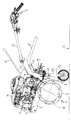
機体前後方向に延びる前機体フレーム1の前側上部にエンジン2を搭載し、後側に伝動軸3を内装する伝動ケース4を支持する。伝動ケース4は機体の左右方向中央部に上下方向に亘って配置し、伝動ケース4の下部から左右両側に耕耘軸5をそれぞれ延設する。そして、エンジン2の駆動軸2aの動力が伝動ベルト8を経て伝動軸3に伝動し、次いで伝動軸3から耕耘軸5に伝動することにより、耕耘軸5に取り付けている多数の耕耘爪6が回転し耕耘作業を行なう構成である。耕耘軸5の左右両端にはサイドディスク7を設けている。
The
エンジン2の上部には燃料タンク10を設け、前機体フレーム1の前端部には上向きに取り付けられるバンパー11を設けている。燃料タンク10の後方には操作ハンドル13と、後機体フレーム21に取り付けた変速レバー14を備えている。
A
耕耘爪6の上側を耕耘カバー15で覆って耕耘部Kを構成し、耕耘部Kの後部には畝を形成する培土板Bと、遊転する左右一対の車輪17を設けている。培土板Bの上方には「く」の字状の抵抗棒18を縦姿勢に保持する縦ホルダー19と、抵抗棒18を横姿勢に保持する横ホルダー20を設け、それぞれ後機体フレーム21に取り付ける構成である。
The tilling part K is configured by covering the upper side of the
次に車輪17と培土板Bの構成について図4と図5に基づいて説明する。
培土板Bは背面視で逆台形状に形成する平面の鉄板で、左右両端に後方に向かって屈曲する屈曲部22を形成している。また、上部の左右中央には切欠き部23を形成し、該切欠き部23には中割れするゴム板24を取りつける構成としている。
Next, the structure of the
The cultivating plate B is a flat iron plate formed in an inverted trapezoidal shape when viewed from the back, and has
左右一対の車輪17はそれぞれ培土板Bの下部の左右両端部の後方に対向する位置に設け、それぞれ支持体25で支持される構成である。左右の支持体25は横軸芯の回動軸26で連結し、回動軸26が回動すると左右の支持体25及び車輪17が共に前後方向に回動する構成である。
The pair of left and
培土板Bは支持体25に連結して左右の車輪17及び支持体25と共に回動する構成で、支持体25の上部と培土板Bの上部とを連結する上部連結板30と、支持体25の下部と培土板Bの下部とを連結する下部連結板31とで連結する構成である。上部連結板30は一端を培土板Bに固着し、他端を支持体25にピンで固定し、支持体25に対して横軸芯に回動自在に構成している。
The cultivating board B is connected to the
下部連結板31は培土板B側に固着する固定部31aと、支持体25側に連結する調節部31bとで構成し、固定部31aと調節部31bとはリンク動作可能に連結すると共に、調節部31bには長孔31dを形成して培土板Bの下部と車輪17との前後方向の距離を変更する構成である。
The lower connecting plate 31 includes a
支持体25の回動軸26の外周を回動軸26を支持する中空状の回動支持軸32で覆い、回動支持軸32の外周には後機体フレーム21側に固定する固定具35と、位置合わせ孔27aを形成した位置合わせプレート27を取り付けている。また、回動軸26側には側面視扇形で複数個所の位置決め孔m、n、pを形成した位置決めプレート33を取り付けている。そして、位置決めピン34で位置決め孔m、n、pのいずれかと位置合わせ孔27aを合わせて挿入し、支持体25、すなわち車輪17と培土板Bの位置を培土作業位置、運搬作業位置、耕耘作業位置に変更する構成である。
The outer periphery of the
次に耕耘しながら畝を形成する培土作業と、非耕耘時の歩行型耕耘機を移動する運搬作業と、通常の耕耘作業について説明する。
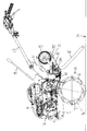
培土作業時(図1及び図5の(ロ)参照)は培土板Bと車輪17との距離が広くなる位置に調節部31bを調節して固定ボルト31cで位置固定する。位置決めピン34を培土作業位置孔mと位置合わせ孔27aに挿入して支持体25を斜め後姿勢として車輪17を接地すると、培土板Bが支持体25より急傾斜の斜め後姿勢となり下端部が培土作用時に圃場Hに作用する姿勢となる。そして、作業者が操作ハンドル13を把持して耕耘部Kの回転による推進力で圃場を耕耘し、耕耘した土を培土板Bの前面で受けて左右両側に押し出し、屈曲部22の面で案内及び押圧することで左右に畝の傾斜面を形成する。このとき、車輪17は耕耘深さを一定になるように調節する役割を果たしている。また、培土作業時には抵抗棒18は不要なので横ホルダ20に前後方向長手姿勢に収納し、運転操作および培土作業いずれにも邪魔しないようにしている。
Next, the cultivation work for forming the ridge while plowing, the transporting work for moving the walking type tiller during non-plowing, and the normal cultivating work will be described.
At the time of cultivating work (see FIGS. 1 and 5 (B)), the adjusting
運搬作業時(図2及び図5の(イ)参照)には、培土板Bと車輪17との距離が狭くなる位置に調節部31bを調節して固定ボルト31cで位置固定する。位置決めピン33を運搬作業位置孔nと位置合わせ孔27aに挿入して、支持体25を地面に対して急傾斜又は略垂直の姿勢にして車輪を接地すると、培土板Bが斜め前姿勢となって圃場から非作用位置まで上方に離間する。また、運転者が操作ハンドル13を押し下げると、耕耘部Kも地面から離間し、機体前側が斜め上向きになり、機体が運搬姿勢となる。このとき、培土板Bは耕耘爪6の耕耘回転軌跡G内に入らない構成としている。
At the time of carrying work (see (a) in FIGS. 2 and 5), the adjusting
通常の耕耘作業時(図3及び図5の(ハ)参照)は車輪17と培土板Bは不要のため上方に回動して位置決めピン33を耕耘作業位置孔pと位置合わせ孔27aに挿入して支持体25を後斜め上姿勢にする。そして、抵抗棒18を縦ホルダー19で縦方向長手姿勢に保持し、下端部を圃場面Hに作用させる。このとき、抵抗棒18は培土板Bの切欠き部23のゴム板24の中割れ部を貫通する構成である。
During normal tillage work (see (c) in FIGS. 3 and 5), the
そして、作業者が操作ハンドル13を把持して耕耘部Kの回転の推進力で耕耘作業がなされる。 Then, the operator grips the operation handle 13 and performs the tilling work with the driving force of the rotation of the tilling portion K.
13 操作ハンドル
17 転輪
25 支持体
K 耕耘部
B 培土板
13 Operation handle 17
Claims (1)
転輪(17)は左右一対設けると共に、培土板(B)の背面の下部と対向する位置に設け、
転輪(17)を支持する支持体(25)と培土板(B)の背面側を連結板で連結する構成とし、
培土板(B)に抵抗棒(18)を貫通する切欠部(23)を設け、
転輪(17)と培土板(B)は、一体となって横軸芯回りに回動可能に構成されることで、上方の非作業位置に退避する耕耘作業位置、又は、地面側に位置する培土作業位置に位置決めピン(34)にて位置決め可能に構成し、
培土作業位置では、転輪(17)の前側に培土板(B)が位置すると共に、培土板(B)が斜め後下がり姿勢とすることを特徴とする歩行型耕耘機。 An operation handle (13), a cultivating section (K) for cultivating the field , and an inverted trapezoidal and flat cultivating board (B) which is located opposite the rear of the cultivating section (K) and forms a ridge. In the walking type tiller provided with the wheel (17) and the resistance rod (18) ,
A pair of wheels (17) is provided on the left and right sides, and is provided at a position facing the lower part of the back surface of the soil-carrying plate (B),
The support (25) that supports the wheel (17) and the back side of the culture plate (B) are connected by a connecting plate,
A notch (23) that penetrates the resistance rod (18) is provided in the culture plate (B),
The rolling wheel (17) and the cultivating board (B) are configured so as to be rotatable around the horizontal axis so that they are retracted to the upper non-working position or positioned on the ground side. It can be positioned with the positioning pin (34) at the earthing work position to be
A walking-type field cultivator characterized in that, in the cultivating work position, the cultivating board (B) is positioned in front of the wheel (17), and the cultivating board (B) is in a slanting rear-down posture.
Priority Applications (1)
| Application Number | Priority Date | Filing Date | Title |
|---|---|---|---|
| JP2010169250A JP5760344B2 (en) | 2010-07-28 | 2010-07-28 | Walk-type field cultivator |
Applications Claiming Priority (1)
| Application Number | Priority Date | Filing Date | Title |
|---|---|---|---|
| JP2010169250A JP5760344B2 (en) | 2010-07-28 | 2010-07-28 | Walk-type field cultivator |
Related Child Applications (3)
| Application Number | Title | Priority Date | Filing Date |
|---|---|---|---|
| JP2013017286A Division JP5700058B2 (en) | 2013-01-31 | 2013-01-31 | Walk-type field cultivator |
| JP2013135202A Division JP5772887B2 (en) | 2013-06-27 | 2013-06-27 | Walk-type field cultivator |
| JP2013200020A Division JP5761291B2 (en) | 2013-09-26 | 2013-09-26 | Walk-type field cultivator |
Publications (3)
| Publication Number | Publication Date |
|---|---|
| JP2012029574A JP2012029574A (en) | 2012-02-16 |
| JP2012029574A5 JP2012029574A5 (en) | 2013-10-17 |
| JP5760344B2 true JP5760344B2 (en) | 2015-08-12 |
Family
ID=45843781
Family Applications (1)
| Application Number | Title | Priority Date | Filing Date |
|---|---|---|---|
| JP2010169250A Active JP5760344B2 (en) | 2010-07-28 | 2010-07-28 | Walk-type field cultivator |
Country Status (1)
| Country | Link |
|---|---|
| JP (1) | JP5760344B2 (en) |
Families Citing this family (5)
| Publication number | Priority date | Publication date | Assignee | Title |
|---|---|---|---|---|
| CN103380665A (en) * | 2012-05-04 | 2013-11-06 | 苏州科瓴精密机械科技有限公司 | Land processing tool |
| JP6135153B2 (en) * | 2013-01-30 | 2017-05-31 | 井関農機株式会社 | Management machine |
| JP6002601B2 (en) * | 2013-02-27 | 2016-10-05 | 三菱マヒンドラ農機株式会社 | Walking type management machine |
| CN104756624B (en) * | 2013-05-02 | 2017-03-08 | 浙江亚特电器有限公司 | A kind of rotary cultivator |
| CN116530240B (en) * | 2023-05-31 | 2024-03-08 | 广宁县木格农业机械有限公司 | Detachable miniature cultivator |
Family Cites Families (9)
| Publication number | Priority date | Publication date | Assignee | Title |
|---|---|---|---|---|
| JPS6024081Y2 (en) * | 1977-11-26 | 1985-07-18 | 株式会社クボタ | Cultivating soil equipment |
| JPS5981302U (en) * | 1982-11-19 | 1984-06-01 | 渡辺 英明 | Furrowing machine with adjustable tillage depth |
| NL8204577A (en) * | 1982-11-24 | 1984-06-18 | Johannes Martinus Josephus Adr | GROUND TILLING DEVICE WITH GROUNDCUTTER AND EARTHING DEVICE. |
| JPS59127406U (en) * | 1983-02-18 | 1984-08-28 | 株式会社クボタ | Structure of the guide wheel attachment part of a walk-behind work vehicle |
| JPS59220104A (en) * | 1983-05-30 | 1984-12-11 | 井関農機株式会社 | Connector apparatus of ridge forming machine of rice field in plowing apparatus |
| JPS6064001U (en) * | 1983-10-08 | 1985-05-07 | 鋤柄農機株式会社 | Ridge-standing board with ridge-beating board on which the prime mover is mounted |
| JPH052018Y2 (en) * | 1985-12-20 | 1993-01-19 | ||
| JPH0334704U (en) * | 1989-08-14 | 1991-04-04 | ||
| JP4178710B2 (en) * | 2000-02-29 | 2008-11-12 | 井関農機株式会社 | Front rotary tiller |
-
2010
- 2010-07-28 JP JP2010169250A patent/JP5760344B2/en active Active
Also Published As
| Publication number | Publication date |
|---|---|
| JP2012029574A (en) | 2012-02-16 |
Similar Documents
| Publication | Publication Date | Title |
|---|---|---|
| JP5760344B2 (en) | Walk-type field cultivator | |
| JP5204565B2 (en) | Agricultural machine | |
| JP2012029574A5 (en) | ||
| JP6041018B2 (en) | Walk-type field cultivator | |
| JP6242007B2 (en) | Agricultural machine | |
| JP5761291B2 (en) | Walk-type field cultivator | |
| JP5700058B2 (en) | Walk-type field cultivator | |
| JP5772887B2 (en) | Walk-type field cultivator | |
| JP6183005B2 (en) | Walk-type field cultivator | |
| JP6007842B2 (en) | Walk-type field cultivator | |
| JP6190479B2 (en) | Cultivator | |
| JP5988819B2 (en) | Agricultural machine | |
| JP2014187899A5 (en) | ||
| JP2010166849A (en) | Walking type farm working machine | |
| JP2014018177A (en) | Walking type axle management machine | |
| JP4605755B2 (en) | Forward and reverse claw-type tillage device for management machine | |
| JP5786321B2 (en) | Walk-type field cultivator | |
| JP5800005B2 (en) | Walk-type field cultivator | |
| JP2018000121A (en) | Walking type ridge straddling tiller | |
| JP2017006082A (en) | Agricultural implement | |
| JP2015002745A (en) | Walking-type tiller | |
| JP2013183698A (en) | Rotary tiller | |
| JP2008237095A (en) | Walking-type husbandry machine | |
| JP2008035826A (en) | Farming tractor | |
| JP3065014U (en) | Tillage residual tillage treatment equipment |
Legal Events
| Date | Code | Title | Description |
|---|---|---|---|
| A621 | Written request for application examination |
Free format text: JAPANESE INTERMEDIATE CODE: A621 Effective date: 20130723 |
|
| A521 | Written amendment |
Free format text: JAPANESE INTERMEDIATE CODE: A523 Effective date: 20130902 |
|
| A977 | Report on retrieval |
Free format text: JAPANESE INTERMEDIATE CODE: A971007 Effective date: 20140522 |
|
| A131 | Notification of reasons for refusal |
Free format text: JAPANESE INTERMEDIATE CODE: A131 Effective date: 20140603 |
|
| A521 | Written amendment |
Free format text: JAPANESE INTERMEDIATE CODE: A523 Effective date: 20140724 |
|
| TRDD | Decision of grant or rejection written | ||
| A01 | Written decision to grant a patent or to grant a registration (utility model) |
Free format text: JAPANESE INTERMEDIATE CODE: A01 Effective date: 20150512 |
|
| A61 | First payment of annual fees (during grant procedure) |
Free format text: JAPANESE INTERMEDIATE CODE: A61 Effective date: 20150525 |
|
| R150 | Certificate of patent (=grant) or registration of utility model |
Ref document number: 5760344 Country of ref document: JP Free format text: JAPANESE INTERMEDIATE CODE: R150 |