JP5759884B2 - Thermally assisted magnetic recording head and method and system for dissipating thermal energy in an optical near-field transducer - Google Patents
Thermally assisted magnetic recording head and method and system for dissipating thermal energy in an optical near-field transducer Download PDFInfo
- Publication number
- JP5759884B2 JP5759884B2 JP2011278148A JP2011278148A JP5759884B2 JP 5759884 B2 JP5759884 B2 JP 5759884B2 JP 2011278148 A JP2011278148 A JP 2011278148A JP 2011278148 A JP2011278148 A JP 2011278148A JP 5759884 B2 JP5759884 B2 JP 5759884B2
- Authority
- JP
- Japan
- Prior art keywords
- heat sink
- field transducer
- optical near
- magnetic recording
- optical
- Prior art date
- Legal status (The legal status is an assumption and is not a legal conclusion. Google has not performed a legal analysis and makes no representation as to the accuracy of the status listed.)
- Expired - Fee Related
Links
Images


Classifications
-
- G—PHYSICS
- G11—INFORMATION STORAGE
- G11B—INFORMATION STORAGE BASED ON RELATIVE MOVEMENT BETWEEN RECORD CARRIER AND TRANSDUCER
- G11B5/00—Recording by magnetisation or demagnetisation of a record carrier; Reproducing by magnetic means; Record carriers therefor
- G11B5/127—Structure or manufacture of heads, e.g. inductive
- G11B5/187—Structure or manufacture of the surface of the head in physical contact with, or immediately adjacent to the recording medium; Pole pieces; Gap features
-
- G—PHYSICS
- G11—INFORMATION STORAGE
- G11B—INFORMATION STORAGE BASED ON RELATIVE MOVEMENT BETWEEN RECORD CARRIER AND TRANSDUCER
- G11B5/00—Recording by magnetisation or demagnetisation of a record carrier; Reproducing by magnetic means; Record carriers therefor
- G11B5/127—Structure or manufacture of heads, e.g. inductive
- G11B5/31—Structure or manufacture of heads, e.g. inductive using thin films
- G11B5/3109—Details
- G11B5/313—Disposition of layers
- G11B5/3133—Disposition of layers including layers not usually being a part of the electromagnetic transducer structure and providing additional features, e.g. for improving heat radiation, reduction of power dissipation, adaptations for measurement or indication of gap depth or other properties of the structure
- G11B5/314—Disposition of layers including layers not usually being a part of the electromagnetic transducer structure and providing additional features, e.g. for improving heat radiation, reduction of power dissipation, adaptations for measurement or indication of gap depth or other properties of the structure where the layers are extra layers normally not provided in the transducing structure, e.g. optical layers
-
- G—PHYSICS
- G11—INFORMATION STORAGE
- G11B—INFORMATION STORAGE BASED ON RELATIVE MOVEMENT BETWEEN RECORD CARRIER AND TRANSDUCER
- G11B5/00—Recording by magnetisation or demagnetisation of a record carrier; Reproducing by magnetic means; Record carriers therefor
- G11B5/127—Structure or manufacture of heads, e.g. inductive
-
- G—PHYSICS
- G11—INFORMATION STORAGE
- G11B—INFORMATION STORAGE BASED ON RELATIVE MOVEMENT BETWEEN RECORD CARRIER AND TRANSDUCER
- G11B5/00—Recording by magnetisation or demagnetisation of a record carrier; Reproducing by magnetic means; Record carriers therefor
- G11B2005/0002—Special dispositions or recording techniques
- G11B2005/0005—Arrangements, methods or circuits
- G11B2005/0021—Thermally assisted recording using an auxiliary energy source for heating the recording layer locally to assist the magnetization reversal
Landscapes
- Engineering & Computer Science (AREA)
- Manufacturing & Machinery (AREA)
- Physics & Mathematics (AREA)
- Electromagnetism (AREA)
- Recording Or Reproducing By Magnetic Means (AREA)
- Magnetic Heads (AREA)
Description
概要
本明細書において記載されクレームされている実現例は、光学近接場変換器およびヒートシンクアセンブリを備えた熱アシスト磁気記録ヘッドを提供する。ヒートシンクアセンブリは、光学近接場変換器と熱伝導接触し、かつ対流冷却面を有する。
Overview The implementation described and claimed herein provides a thermally assisted magnetic recording head with an optical near-field transducer and a heat sink assembly. The heat sink assembly is in thermal conductive contact with the optical near field transducer and has a convective cooling surface.
その他の実現例も本明細書において記載され詳述される。 Other implementations are also described and detailed herein.
詳細な説明
熱アシスト磁気記録(HAMR:Heat Assisted Magnetic Recording)技術は、データを、安定性が高い媒体に、集束させた光を用いてまず媒体を加熱することにより、磁気記録する。HAMR技術は、鉄と白金の合金といった安定性が高い磁性化合物を利用して媒体を構成する。こうした材料は、単一ビットをより小さな領域に記憶することができるが、磁気媒体記憶に使用される従来技術を制限するのと同じ超常磁性効果による制限は受けない。しかしながら、この高安定性の磁性化合物は、媒体上の磁性配向を変化させるために、まず加熱しなければならない。
DETAILED DESCRIPTION Heat assisted magnetic recording (HAMR) technology magnetically records data by first heating the medium using focused light onto a highly stable medium. In the HAMR technology, a medium is formed using a highly stable magnetic compound such as an alloy of iron and platinum. Such materials can store a single bit in a smaller area, but are not limited by the same superparamagnetic effects that limit the prior art used for magnetic media storage. However, this highly stable magnetic compound must first be heated in order to change the magnetic orientation on the medium.
ある実現例において、HAMRヘッドは、少なくとも光学近接場変換器(NFT:Near-Field Transducer)と書込極とを含む。光学NFTは、光を集めて媒体に集束させるのに使用される。集束させた光は、媒体上のスポットの温度を、書込極によって磁性配向を変化させるのに十分に高い温度まで上昇させる(たとえば数百度の温度上昇)。しかしながら、光学NFTが光を集めて集束させたときに生じる極端な熱は、光学NFTの動作寿命を著しく制限する。 In some implementations, the HAMR head includes at least an optical near-field transducer (NFT) and a write pole. Optical NFT is used to collect light and focus it on a medium. The focused light raises the temperature of the spot on the medium to a temperature high enough to change the magnetic orientation by the write pole (eg, a temperature increase of several hundred degrees). However, the extreme heat generated when the optical NFT collects and focuses the light significantly limits the operational lifetime of the optical NFT.
有限要素解析によると、光学NFTの温度は、媒体の磁性配向を変化させるのに十分な光を集束させたときに、セ氏500度を超える可能性がある。現在開示されている技術は、光学NFTの熱管理のためのヒートシンクを開示している。しかしながら問題がいくつかある。第1に、光学NFTは大きさが小さいため(たとえば一般的には幅100nmから200nm)、熱エネルギを放散する表面積が極めて小さい。第2に、光学NFTの近傍に何も配置されていないので、書込極および/または光学NFTの効率または共振周波数が大幅に低下または変化する可能性がある。他の実現例では、HAMRヘッドにさらに他の小型電子部品(たとえば1つ以上の読取機およびセンサ)が含まれている。光学NFTの近傍に何も配置されていないと、これらのさらなる小型電子部品のうちいずれかの効率または共振周波数が大幅に変化する可能性がある。 According to finite element analysis, the temperature of the optical NFT can exceed 500 degrees Celsius when focusing enough light to change the magnetic orientation of the medium. Currently disclosed techniques disclose heat sinks for thermal management of optical NFTs. However, there are some problems. First, because the optical NFT is small (eg, typically 100 nm to 200 nm in width), the surface area that dissipates thermal energy is very small. Second, since nothing is placed in the vicinity of the optical NFT, the efficiency or resonant frequency of the write pole and / or optical NFT can be significantly reduced or changed. In other implementations, the HAMR head further includes other small electronic components (eg, one or more readers and sensors). If nothing is placed in the vicinity of the optical NFT, the efficiency or resonant frequency of any of these additional small electronic components can change significantly.
よって、現在開示されているヒートシンクおよびヒートシンクアセンブリは、光学NFTから熱エネルギを抽出し、この熱エネルギを、HAMRヘッドの周りの空気への対流、HAMRヘッドに隣接する面(たとえば磁気媒体)への放射、および/またはHAMRヘッドの他の部品への伝導によって、伝達する。他の実現例では、光学NFTおよびヒートシンクを、HAMRヘッド以外の記録ヘッドにおいて利用する。 Thus, the presently disclosed heat sinks and heat sink assemblies extract thermal energy from the optical NFT and convect this thermal energy to the air around the HAMR head, to a surface adjacent to the HAMR head (eg, a magnetic medium). Transmit by radiation and / or conduction to other parts of the HAMR head. In other implementations, optical NFTs and heat sinks are utilized in recording heads other than HAMR heads.
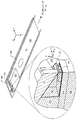
図1は、その遠位端に設けられた封入ヒートシンク112を利用するHAMRヘッド106を備えたアクチュエータアームフレキシャ102の一例を示す。座標軸が示されており、y方向は、フレキシャ102の長手方向においてフレキシャ102の遠位端に向かって延び、x方向は、対応する磁気媒体(図示せず)に対して平行な方向においてフレキシャ102を横断して延び、z方向は、磁気媒体に向かって下向きに延びる。アクチュエータアームフレキシャ102は、y方向に延びるカンチレバーアクチュエータアーム(図示せず)に装着される。アクチュエータアームフレキシャ102は、z軸方向において調整されて磁気媒体上の磁気ビットの1以上のトラックを追従することができる。HAMRヘッド106を備えたエアベアリングスライダ(ABS:Air Bearing Slider)104は、磁気媒体(図示せず)に対向するフレキシャ102の面上において、フレキシャ102の遠位端に設けられる。スライダ104によって、HAMRヘッド106は、磁気媒体の対応する面の上でこの面に接近して浮動することができる。電線(たとえばワイヤ108)が、フレキシャ102に沿って概ねy方向に延び、最終的にHAMRヘッド106に接続するスライダ104上のコンタクトパッド(たとえばパッド110)に装着される。処理電子装置(図示せず)に/から送られる読取/書込およびその他の電気信号は、電線およびコンタクトパッドを介してHAMRヘッド106まで送られる。
FIG. 1 shows an example of an
図1には、HAMRヘッド106を回転させて拡大したものの断面図も示されている。このHAMRヘッド106は、x軸を中心として90度、z軸を中心として90度回転させて拡大したものであり、HAMRヘッド106の断面はHAMRヘッド106の中心を通るyz面であるので、HAMRヘッド106内のさまざまな構成要素の向きが明らかになっている。基板124は、HAMRヘッド106の構成要素の載置面の役割を果たし、HAMRヘッド106をABS104に接続している。基板124上に設けられた導波管コア114は、光波を光学NFT116に伝達し、NFT116は、光を集束させて磁気媒体(図示せず)上の一点に導く。
FIG. 1 also shows a cross-sectional view of the
典型的には、光学NFT(たとえば光学NFT116)は、HAMRヘッド内における光学導波管クラッド材料として機能するAl2O3によって囲まれている。Al2O3の光学特性は導波管に適しているが、Al2O3の熱伝導率は非常に低い(たとえば1.35W/m/K)。これは、光学NFTが吸収したエネルギを熱エネルギとして実質的に取込み、光学NFTの動作寿命を大幅に制限する。 Typically, an optical NFT (eg, optical NFT 116) is surrounded by Al 2 O 3 that functions as an optical waveguide cladding material in the HAMR head. Although the optical properties of Al 2 O 3 are suitable for waveguides, the thermal conductivity of Al 2 O 3 is very low (eg 1.35 W / m / K). This substantially captures the energy absorbed by the optical NFT as thermal energy and greatly limits the operational life of the optical NFT.
このAl2O3の短所を克服する1つの方法は、光学NFTを、ヒートシンクとして使用される光学品質を有する誘電体のブロックで囲むまたは封入することである。このヒートシンクは、Al2O3よりも熱伝導率が高くかつ光学NFTから有効に熱を伝達するのに十分大きくなければならない。さらに、ヒートシンクは、光学NFTの共鳴に大きな影響を及ぼさないおよび/または導波管損失を生じさせないように、十分小さくおよび/または配向されていなければならない。ある実現例では、光学NFTの1つの構成要素の直径は200nmである。ヒートシンクは、光学NFTと十分に接触するのに足る大きさである必要がある。またさらに、ヒートシンクは、HAMRヘッド内の他の小型電子部品(たとえば1つ以上の読取機およびセンサ)いずれにも大きな影響を及ぼさないように、十分小さくおよび/またはHAMRヘッド内において配向されていなければならない。ある実現例において、ヒートシンクは、結晶相で作ることができるさまざまな金属化合物(たとえばMgO、MgF2、LiF、CaF2、BaF2、BeO、ZnO、Si3N4、および/またはAlN)で構成してもよい。 One way to overcome this disadvantage of Al 2 O 3 is to enclose or encapsulate the optical NFT with an optical quality dielectric block used as a heat sink. This heat sink must have a higher thermal conductivity than Al 2 O 3 and be large enough to effectively transfer heat from the optical NFT. In addition, the heat sink must be sufficiently small and / or oriented so as not to significantly affect the resonance of the optical NFT and / or cause waveguide loss. In one implementation, the diameter of one component of the optical NFT is 200 nm. The heat sink needs to be large enough to make sufficient contact with the optical NFT. Still further, the heat sink must be small enough and / or oriented in the HAMR head so as not to significantly affect any other small electronic components (eg, one or more readers and sensors) in the HAMR head. I must. In certain implementations, the heat sink is composed of various metal compounds (eg, MgO, MgF 2 , LiF, CaF 2 , BaF 2 , BeO, ZnO, Si 3 N 4 , and / or AlN) that can be made in a crystalline phase. May be.
図1に示される光学NFT116は、ヒートシンク112(太線で示される)で囲まれている。ヒートシンク112は、光学NFT116がヒートシンク112内に設けられた状態で導波管コア114上に設けられる。光学NFT116から離れた場所において、従来の光学導波管クラッド材料118(たとえばAl2O3)が用いられる。書込極120は、ヒートシンク112および/またはクラッド材料118の上に設けられる。
The
ある実現例では、ヒートシンク112は、熱エネルギを光学NFT116から伝導によって抽出し、この熱エネルギを周囲のHAMRヘッド106の構成要素(たとえば導波管コア114、クラッド材料118、および/または書込極120)に伝導によって伝達すする。別の実現例では、ヒートシンク112は、熱エネルギを、磁気媒体に対向するヒートシンク112のエアベアリング面122から概ねz方向に位置する隣の磁気媒体(図示せず)に、放射によって伝達する。さらに他の実現例では、ヒートシンク112は、熱エネルギを、エアベアリング面の隣で移動している空気に、対流によって伝達する。さらに他の実現例では、ヒートシンク112は、伝導、放射、および対流による熱エネルギの伝達を組合せたものを利用して光学NFT116の温度を管理する。
In one implementation, the heat sink 112 extracts thermal energy from the
ヒートシンクを備えていないHAMRヘッド内の光学NFTのある実現例では、光学NFTの温度はHAMRヘッドの動作中に500℃を超える。ヒートシンクを追加すると、ヒートシンクの熱伝導率と動作中の光学NFTの温度上昇との間の逆の関係が明らかになる。ある実現例では、図1に示されるヒートシンクは、エアベアリング面122から負のz方向に0.5ミクロン、トラックを横断する方向(すなわちx方向)に0.5μm延びる。ヒートシンクの熱伝導率が5W/m/Kの場合、光学NFTの温度は、HAMRヘッドの動作中に約275℃上昇する。ヒートシンクの熱伝導率が20W/m/Kの場合、光学NFTの温度は、HAMRヘッドの動作中に約150℃上昇する。
In one implementation of optical NFT in a HAMR head that does not include a heat sink, the temperature of the optical NFT exceeds 500 ° C. during operation of the HAMR head. Adding a heat sink reveals an inverse relationship between the thermal conductivity of the heat sink and the temperature rise of the optical NFT during operation. In one implementation, the heat sink shown in FIG. 1 extends from the
図2Aは、書込極220およびヨーク226の一例の斜視図を示す。書込極220(実線で示す)は、ヨーク226(点線で示す)に装着され、ヨーク226からz方向および負のy方向に延びる。ヨーク226は、オフヘッド処理電子機器(図示せず)から書込信号を受ける磁気コイル(図示せず)に装着される。ヨーク226は、磁気コイルからの書込信号を書込極220に伝達し、これは、書込信号を媒体に与えて媒体上のビットの磁気分極を変化させることにより、データを書込信号から媒体に書込む。
FIG. 2A shows a perspective view of an example of
HAMRヘッド内において、光学NFT(図示せず)は、示されている書込極220およびヨーク226の隣に位置する。ある実現例では、書込極220から熱エネルギを伝導によって抽出することは、光学NFTからの熱エネルギの抽出を促進する。
Within the HAMR head, an optical NFT (not shown) is located next to the
図2Bは、図2Aの書込極220およびヨーク226に金属被覆ヒートシンク228の一例が設けられたものを示す。ヒートシンク228(太線で示す)は、書込極220を被覆し、書込極220からx方向および負のx方向に延びている。ある実現例において、ヒートシンク228は、x方向および負のx方向(すなわちトラックを横断する方向)に数ミクロン(たとえば4μm〜20μm)、y方向およびz方向の厚みはわずか10分の数ミクロンである。この実現例では、ヒートシンク228の大きさおよび表面積は、光学NFTの温度を25%から30%低下させるのに十分である。ある実現例において、優れた熱伝導率を有する1以上の金属を用いて金属被覆部(たとえばCr、Ru、Cu、Au、Ag、Al、Ni、Ir、Pt、W、Ti、Mo、Zr、Rh、Pd、V、およびその合金またはそれをドーピングしたもの)を形成してもよい。
FIG. 2B shows an example in which the metal
図3は、金属被覆ヒートシンク328を備えた書込極320を有するHAMRヘッド300の一例の部分斜視図の断面を示す。図3は、図2Bに示される書込極220とヒートシンク228との間の界面を詳細に示している。ヒートシンク328は、書込極320からx方向およびy方向に延びる。さらに、示されている実現例では、ヒートシンク328は実際光学NFT316に接触していない。熱エネルギは、書込極320および周囲にある任意のクラッド材料318を介して、光学NFT316からヒートシンク328に伝達される。
FIG. 3 shows a cross-sectional view of a partial perspective view of an
ヒートシンク328は、エアベアリング面322における対流による熱エネルギの伝達を利用することにより、光学NFT316からの熱エネルギの放散を最大にする。好ましくは、ヒートシンク328を非磁性金属で構成してサイドトラック消去および/または書込極320に対する干渉のリスクを最小にする。ある実現例において、ヒートシンク328は、成膜後のスライダ加工(たとえばチップをウエハから分離すること、チップをラッピングすること、チップを研磨すること、空気力学的構造をチップ上にパターン形成すること、保護膜をチップ上に設けることなど)と共存し得る。さらに、ヒートシンク328は、媒体の方向に書込極320を超えて突出しない(ヒータがオンで書込極320を媒体に向かって押出すときも、ヒータがオフのときも)。結果として、ヒートシンク328が原因でHAMRヘッド300の後縁に構造上の問題が生じることはない。
The
ある実現例では、ヒートシンク328を、本明細書に開示されている他の熱エネルギ放散装置のうち1つ以上と組合せてもよい。具体的には、ヒートシンク328は、図4Bおよび図5に示される翼状のヒートシンク432、532とともに使用したときに特に効果的である。本明細書に開示されているヒートシンクのうち1つ以上との組み合わせのことをヒートシンクアセンブリと呼ぶ。
In certain implementations, the
図4Aは、光学NFT416の一例の斜視図を示す。光学NFT416を用いて光を集めて媒体(図示せず)に集束させる。集束させた光は、媒体上のスポットの温度を、書込極(図示せず)による磁性配向の変化を引起すのに十分高い温度まで、上昇させる。
FIG. 4A shows a perspective view of an example of an
図4Bは、図4Aの光学近接場変換器416に翼状のヒートシンク432および434の一例を設けたものを示す。ヒートシンク432、434(太線で示す)は、光学NFT416の一部を覆い、光学NFT416からx方向およびy方向に延びている。ある実現例では、ヒートシンク432および434は、x方向および負のx方向(すなわちトラックを横断する方向)に数ミクロン(たとえば4μm〜20μm)延び、y方向の厚みは光学NFT416よりも大きい。
FIG. 4B shows an example of the wing-shaped
結果として、ヒートシンク432および434は、ともに使用された場合、図2Bおよび図3のヒートシンク228および328と接触し得る。この組み合わせが光学NFTの光学効率に与える影響はほとんどまたは全くない。ともに使用されたとき、ヒートシンク228、328および432、434の大きさおよび表面積は、光学NFTの温度を最大50%低下させるのに十分である。ある実現例において、優れた熱伝導率を有する1以上の金属(たとえばCr、Ru、Cu、Au、Ag、Al、Ni、Ir、Pt、W、Ti、Mo、Zr、Rh、Pd、V、およびその合金またはそれをドーピングしたもの)を用いてヒートシンク432および434を形成してもよい。実現例によっては、ヒートシンク432および434を光学NFT416と同じ材料で構成してもよい。
As a result,
図5は、翼状のヒートシンク532を備えた光学NFT516を有するHAMRヘッド500の一例の部分斜視図の断面を示す。図5は、光学NFT516と、翼状ヒートシンク532と、書込極520との間の界面を詳細に示している。ヒートシンク532は、光学NFT516からx方向およびy方向に延びる。熱エネルギは、伝導により、光学NFT516からヒートシンク532に伝わる。次に、熱エネルギは、ヒートシンク532から、周囲の任意のクラッド材料518、導波管コア514、および/または書込極520へと伝導される。さらに、エアベアリング面522での対流による熱エネルギ伝達は、ヒートシンク532から熱エネルギを運ぶ。
FIG. 5 shows a cross-sectional view of a partial perspective view of an
翼状のヒートシンク532からの熱エネルギの伝導による伝達を改善するために、ヒートシンク532を図2Aおよび図3のヒートシンク228、328とともに使用してもよい。エアベアリング面522におけるヒートシンク228、328の表面積が比較的大きいために、対流による熱エネルギの伝達は、ヒートシンク532のみを用いる実現例と比較すると、遥かに大きい。他の実現例では、ヒートシンク532を、本明細書に開示されている他の熱エネルギ放散装置のうち1つ以上と組合せてもよい。
The
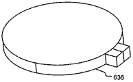
図6Aは、円形の光学NFT636の一例の斜視図を示す。この円形の光学NFT636は、光を集めて媒体(図示せず)に集束させるのに使用される。集束させた光は、媒体上のスポットの温度を、書込極(図示せず)による磁性配向の変化を引起すのに十分高い温度まで、上昇させる。
FIG. 6A shows a perspective view of an example of a circular
図6Bは、図6Aの円形の光学NFT636に円錐台形状のヒートシンク638の一例を設けたものを示す。ヒートシンク638(太線で示す)は、光学NFT636を覆い、光学NFT636からy方向に延びて円錐台を形成する。ある実現例では、ヒートシンク636は、y方向に1ミクロンの何分の1かにわたって(たとえば50nm〜250nm)延びる。
FIG. 6B shows an example in which the circular
図7は、円錐台形状のヒートシンク738を備えた円形の光学NFT736を有するHAMRヘッド700の一例の部分斜視図の断面を示す。ヒートシンク738は、光学NFT736と書込極720との間でy方向に延びている。熱エネルギは、伝導によって光学NFT736からヒートシンク738に伝わる。次に、このエネルギは、ヒートシンク738から書込極720および周囲の任意のクラッド材料718に伝導される。他の実現例では、ヒートシンク738を本明細書に開示される他のヒートシンクのうち1つ以上と組合せてもよい。
FIG. 7 shows a cross-section of a partial perspective view of an
ある実現例において、優れた熱伝導率を有する1以上の金属(たとえばCr、Ru、Cu、Au、Ag、Al、Ni、Ir、Pt、W、Ti、Mo、Zr、Rh、Pd、V、およびその合金またはそれをドーピングしたもの)を用いてヒートシンク738を形成してもよい。実現例によっては、ヒートシンク738を形成するために選択された材料を、光学NFT736のカップリング効率の維持にも適合したものにする。プラズモニック(plasmonic)金属(たとえばAu、Ag、Cu、Al、Pd、V、およびその合金またはそれをドーピングしたもの)は、光学NFT736のカップリング効率を維持するのに特に有効である。実現例によっては、ヒートシンク738を光学NFT736と同じ材料で構成してもよい。ある実現例では、ヒートシンク738は、ウエハ処理中に、光学NFT736と書込極720とを薄膜成長方向(すなわちy方向)において接続する。
In some implementations, one or more metals having excellent thermal conductivity (eg, Cr, Ru, Cu, Au, Ag, Al, Ni, Ir, Pt, W, Ti, Mo, Zr, Rh, Pd, V, And an alloy thereof, or an alloy thereof) may be used to form the
光学NFT736はクラッド材料718およびヒートシンク738によって囲まれている。導波管コア714はクラッド材料718の片側と境を接している。ヒートシンク738は、光学NFT736、クラッド材料718、および書込極720と境を接している。ある実現例では、ヒートシンク738の底の断面の寸法は、光学NFT736の円形部分と同一である。ヒートシンク738が円錐台形状で延びている様子を示しているが、ヒートシンクは円筒の一部の形またはその他の形状で延びていてもよい。
光学NFTから熱エネルギを十分に伝導するのに足りる大きさのヒートシンクのxz断面積は、光学NFTの理想的なxz断面積よりも大きいことが多い。図6Bおよび図7の実現例では、光学NFT636、736は、円錐台形状のヒートシンク638、738の底の断面形状と一致させるのに必要な大きさよりも大きくされる。この場合、光学NFT636、736の効率は約30%低下するかもしれないが、光学NFT636、736から放散するパワーは、光学NFTがより小さい場合(たとえば図5の光学NFT516参照)と比較して、約55%増加し得る。なぜなら、光学NFT636、736からヒートシンク638、738および書込極620、720への伝導による熱エネルギの伝達が増すからである。さらに、他に特別な条件がない限り、光学NFT636、736の動作中は、ヒートシンク638、738のxz断面積と光学NFT636、736の温度上昇との間に逆の関係がある。
The xz cross section of a heat sink that is large enough to conduct heat energy sufficiently from the optical NFT is often larger than the ideal xz cross section of the optical NFT. In the implementation of FIGS. 6B and 7, the
ヒートシンク738のxz断面積を光学NFT736のxz断面積と一致させて熱エネルギ伝達を増大させると、結果として、ヒートシンク738がない理想的な大きさの光学NFTと比較して、光学NFT736における全体的な温度低下は約50%となる場合がある。書込極720は、この実現例において、ヒートシンク738がない実現例と比較すると、50%以上ものパワーを吸収し得る。このようにパワーがさらに吸収されることによって、光学NFTの動作温度が低下して、光学NFTの動作寿命を延ばすことができる。
Increasing the thermal energy transfer by matching the xz cross-sectional area of the
図2Bおよび図3に示されるヒートシンク228、328をヒートシンク738とともに使用した場合、ヒートシンク228、328の体積によって、書込極720に伝導するさらなる熱エネルギのほとんどを放散することができる。結果として、磁気記録ヘッド700の動作中の書込極720の温度は、小さいヒートシンクを用いるまたはヒートシンクを使用しない場合の書込極の温度と同一または略同一であろう。書込極の動作寿命も、動作温度の影響が大きい。ヒートシンク738から書込極720に伝達される熱が書込極720からヒートシンク228または328に伝わるようにすることは、書込極720の所望の動作温度および動作寿命の維持に役立つ。
When the
図8は、現在開示されている技術に従い光学近接場変換器から熱エネルギを伝導させる処理800の例を示す。発生処理805において、HAMRヘッド内での動作時に光学NFT内で熱エネルギが発生する。光学NFTは光を集めて磁気媒体に集束させる。その結果、光学NFTが加熱される。現在開示されているヒートシンクのうち1つ以上を用いて、光学NFT内で発生した熱エネルギを放散してもよい。
FIG. 8 illustrates an
判断処理810において、図1に関連付けて具体的に説明した封入ヒートシンクがHAMRヘッド内にある場合、伝導処理815に進む。HAMRヘッド内に封入ヒートシンクがなければ、発生処理805に戻る。
In
伝導処理815において、光学NFT内で発生した熱エネルギは封入ヒートシンクに伝導される。さらに、光学NFT内で発生した熱エネルギは、光学NFTに隣接するHAMRヘッドの他の構成要素(たとえば導波管クラッドおよび/または別のヒートシンク)にも伝導される。加えて、封入ヒートシンクに伝導された熱エネルギはさらに、封入ヒートシンクに隣接するHAMRヘッドの他の構成要素(たとえば書込極、導波管コア、導波管クラッドおよび/または別のヒートシンク)にも伝導し得る。しかしながら、書込極、導波管コア、および/または導波管に伝達される伝導熱エネルギは、光学NFTおよび/または封入ヒートシンクとの熱接触面積が不十分なので、限定される可能性がある。また、書込極、導波管コア、および/または導波管の材料構成が、熱エネルギの伝達に特に適していない可能性もある。
In
判断処理820において、図4Bおよび図5に関連付けて具体的に説明した翼状のヒートシンクがHAMRヘッド内にある場合、伝導処理825に進む。翼状のヒートシンクがHAMRヘッド内になければ、発生処理805に戻る。
In
伝導処理825において、光学NFT内で発生した熱エネルギは翼状のヒートシンクに伝導される。さらに、光学NFT内で発生した熱エネルギは、光学NFTに隣接するHAMRヘッドの他の構成要素(たとえば導波管クラッドおよび/または別のヒートシンク)にも伝導し得る。加えて、翼状のヒートシンクに伝導された熱エネルギはさらに、翼状のヒートシンクに隣接するHAMRヘッドの他の構成要素(たとえば書込極、導波管コア、導波管クラッドおよび/または別のヒートシンク)にも伝導し得る。
In the
判断処理830において、図6Bおよび図7と関連付けて具体的に説明した円錐台形状のヒートシンクがHAMRヘッド内にある場合、伝導処理835に進む。円錐台形状のヒートシンクがHAMRヘッド内になければ、発生処理805に戻る。
In
伝導処理835において、光学NFT内で発生した熱エネルギは円錐台形状のヒートシンクに伝導される。さらに、光学NFT内で発生した熱エネルギは、光学NFTに隣接するHAMRヘッドの他の構成要素(たとえば導波管クラッドおよび/または別のヒートシンク)にも伝導し得る。加えて、円錐台形状のヒートシンクに伝導された熱エネルギはさらに、円錐台形状のヒートシンクに隣接するHAMRヘッドの他の構成要素(たとえば書込極、導波管コア、導波管クラッドおよび/または別のヒートシンク)に伝導し得る。 In the conduction process 835, the thermal energy generated in the optical NFT is conducted to a frustoconical heat sink. Furthermore, the thermal energy generated in the optical NFT may also be conducted to other components of the HAMR head (eg, waveguide cladding and / or another heat sink) adjacent to the optical NFT. In addition, the thermal energy conducted to the frustoconical heat sink may further cause other components of the HAMR head adjacent to the frustoconical heat sink (eg, write pole, waveguide core, waveguide clad and / or To another heat sink).
判断処理840において、図2Bおよび図3と関連付けて具体的に説明した金属で被覆された円錐形のヒートシンクがHAMRヘッド内にある場合、伝導処理845に進む。判断処理840は、円錐台形状のヒートシンク、翼状のヒートシンク、または封入ヒートシンクのうち1つ以上がHAMRヘッド内にある場合に行なわれる。
In
伝導処理845において、光学NFT内で発生した熱エネルギは、導波管クラッド、円錐形のヒートシンク、翼状のヒートシンク、または封入ヒートシンクが存在すればそれを介して金属被覆ヒートシンクに伝導される。さらに、光学NFT内で発生した熱エネルギは、光学NFTに隣接するHAMRヘッドの他の構成要素(たとえば導波管クラッドおよび/または別のヒートシンク)にも伝導し得る。加えて、金属被覆ヒートシンクに伝導された熱エネルギはさらに、金属被覆ヒートシンクに隣接するHAMRヘッドの他の構成要素(たとえば書込極、導波管コア、導波管クラッドおよび/または別のヒートシンク)にも伝導し得る。 In conduction process 845, the thermal energy generated in the optical NFT is conducted to the metal-coated heat sink through the waveguide cladding, conical heat sink, wing heat sink, or encapsulated heat sink, if present. Furthermore, the thermal energy generated in the optical NFT may also be conducted to other components of the HAMR head (eg, waveguide cladding and / or another heat sink) adjacent to the optical NFT. In addition, the thermal energy conducted to the metallized heat sink may further cause other components of the HAMR head adjacent to the metallized heat sink (eg, write pole, waveguide core, waveguide cladding and / or another heat sink). Can also conduct.
伝導処理845に続いて、金属被覆ヒートシンクが存在していれば、または、判断処理840に続いて、金属被覆ヒートシンクが存在していなければ、対流/放射処理850が行なわれる。対流/放射処理850では、対流冷却面(たとえばHAMRヘッド上のエアベアリング面)を形成するHAMRヘッドの1以上の構成要素(たとえば1以上のヒートシンク、書込極、光学NFT、導波管コア、および/または導波管クラッド)内の熱エネルギが、対流によって、HAMRヘッド上のエアベアリング面と磁気媒体の表面との間を通る空気に伝達される。さまざまな実現例において、HAMRヘッドおよび/または磁気媒体面が動いて空気の擾乱が生じ、これによって、対流による熱エネルギの伝達が増す。さらに、対流/放射処理850は、HAMRヘッド上のエアベアリング面から磁気媒体に直接伝達される放射による熱エネルギ伝達も含み得る。
Following the conduction process 845, if a metallized heat sink is present, or following the
他に特別な条件がない限り、エアベアリング面に対して露出したヒートシンクの表面積が大きいほど、対流による熱エネルギ伝達は大きい。さらに、他に特別な条件がない限り、光学NFTに接触するヒートシンクの表面積が大きいほど、伝導による熱エネルギの伝達は大きい。結果として、金属被覆ヒートシンクを円錐形のヒートシンク、翼状のヒートシンク、または封入ヒートシンクとともに用いて、光学NFTからの熱エネルギの伝導、および、エアベアリング面における対流/放射による熱エネルギの伝達双方を、改善し得る。本明細書に開示されているヒートシンクのうち1つ以上を組合せたものをヒートシンクアセンブリと呼ぶ。 Unless otherwise specified, the greater the heat sink surface area exposed to the air bearing surface, the greater the heat energy transfer by convection. Furthermore, unless otherwise specified, the greater the surface area of the heat sink that contacts the optical NFT, the greater the transfer of thermal energy by conduction. As a result, metallized heat sinks can be used with conical, winged, or encapsulated heat sinks to improve both the conduction of thermal energy from the optical NFT and the transfer of thermal energy by convection / radiation at the air bearing surface Can do. A combination of one or more of the heat sinks disclosed herein is referred to as a heat sink assembly.
上記明細書、実施例、およびデータによって、本発明の例示としての実施の形態の構成および用途に関する説明が完成する。本発明の数多くの実施の形態を発明の精神および範囲から逸脱することなく実現できるので、本発明は以下の請求項に帰する。さらに、異なる実施の形態の構造上の特徴を、記載されている請求項の範囲を逸脱することなく別の実施の形態に組込んでもよい。 The above description, examples, and data complete the description of the structure and application of the exemplary embodiments of the invention. Since many embodiments of the invention can be made without departing from the spirit and scope of the invention, the invention resides in the claims hereinafter appended. Moreover, structural features of different embodiments may be incorporated into other embodiments without departing from the scope of the recited claims.
Claims (17)
光学近接場変換器と、
前記光学近接場変換器と熱伝導接触するヒートシンクアセンブリとを備え、
前記ヒートシンクアセンブリは、対流冷却面を有し、かつ書込極と前記光学近接場変換器との間に設けられた第1のヒートシンクを含み、
前記対流冷却面は、前記光学近接場変換器と接している、熱アシスト磁気記録ヘッド。 A heat-assisted magnetic recording head,
An optical near-field transducer;
A heat sink assembly in thermal conductive contact with the optical near field transducer;
The heat sink assembly includes a convection cooling surfaces, and saw including a first heat sink disposed between the write pole and the optical near field transducer,
The thermally assisted magnetic recording head, wherein the convection cooling surface is in contact with the optical near-field transducer .
熱アシスト磁気記録ヘッド。 The thermally assisted magnetic recording head of claim 1, wherein the heat sink assembly includes a second heat sink, wherein the first heat sink is in thermal conductive contact with the second heat sink.
前記光学近接場変換器内に熱エネルギを発生するステップと、
前記光学近接場変換器内の熱エネルギの少なくとも一部を、前記光学近接場変換器と伝導接触するヒートシンクアセンブリに伝導させるステップと、
前記ヒートシンクアセンブリに伝導させた熱エネルギの少なくとも一部を、対流冷却面のエアベアリングに対流によって伝達するステップとを含み、
前記ヒートシンクアセンブリは、前記対流冷却面を有し、かつ書込極と前記光学近接場変換器との間に設けられた第1のヒートシンクを含み、
前記対流冷却面は、前記光学近接場変換器と接している、方法。 A method for dissipating thermal energy in an optical near-field transducer, comprising:
Generating thermal energy in the optical near-field transducer;
Conducting at least a portion of the thermal energy in the optical near field transducer to a heat sink assembly in conductive contact with the optical near field transducer;
Convectively transferring at least a portion of the thermal energy conducted to the heat sink assembly to an air bearing on a convective cooling surface;
The heat sink assembly has the convective cooling surface, and viewing contains a first heat sink disposed between the write pole and the optical near field transducer,
The method wherein the convective cooling surface is in contact with the optical near field transducer .
前記光学近接場変換器と伝導接触する第1のヒートシンクと、
前記第1のヒートシンクと伝導接触する第2のヒートシンクと、
書込極とを備え、
前記第1のヒートシンクおよび前記第2のヒートシンクのうち一方または双方が、対流冷却面を含み、前記書込極と前記光学近接場変換器との間に設けられ、かつ前記光学近接場変換器と接触しており、
前記対流冷却面は、前記光学近接場変換器と接している、システム。 A system for dissipating thermal energy in an optical near-field transducer, comprising:
A first heat sink in conductive contact with the optical near-field transducer;
A second heat sink in conductive contact with the first heat sink;
With a writing pole,
One or both of the first heat sink and the second heat sink includes a convection cooling surface, is provided between the write pole and the optical near field transducer, and the optical near field transducer; In contact ,
The system, wherein the convective cooling surface is in contact with the optical near field transducer .
Applications Claiming Priority (2)
| Application Number | Priority Date | Filing Date | Title |
|---|---|---|---|
| US12/976,559 US9431036B2 (en) | 2010-12-22 | 2010-12-22 | Heat-sinks for optical near-field transducers |
| US12/976,559 | 2010-12-22 |
Publications (3)
| Publication Number | Publication Date |
|---|---|
| JP2012133873A JP2012133873A (en) | 2012-07-12 |
| JP2012133873A5 JP2012133873A5 (en) | 2012-08-23 |
| JP5759884B2 true JP5759884B2 (en) | 2015-08-05 |
Family
ID=46316633
Family Applications (1)
| Application Number | Title | Priority Date | Filing Date |
|---|---|---|---|
| JP2011278148A Expired - Fee Related JP5759884B2 (en) | 2010-12-22 | 2011-12-20 | Thermally assisted magnetic recording head and method and system for dissipating thermal energy in an optical near-field transducer |
Country Status (4)
| Country | Link |
|---|---|
| US (1) | US9431036B2 (en) |
| JP (1) | JP5759884B2 (en) |
| KR (1) | KR101349904B1 (en) |
| CN (1) | CN102592608B (en) |
Families Citing this family (25)
| Publication number | Priority date | Publication date | Assignee | Title |
|---|---|---|---|---|
| US8427925B2 (en) | 2010-02-23 | 2013-04-23 | Seagate Technology Llc | HAMR NFT materials with improved thermal stability |
| US9053737B2 (en) | 2010-12-22 | 2015-06-09 | Seagate Technology Llc | Heat assisted magnetic recording devices |
| US8259540B1 (en) * | 2012-01-16 | 2012-09-04 | Seagate Technology Llc | Heat assisted magnetic recording (HAMR) heads including components made of nickel alloys |
| US9129625B2 (en) | 2012-01-16 | 2015-09-08 | Seagate Technology Llc | Perpendicular magnetic recording heads including components made of nickel alloys |
| US8526275B1 (en) * | 2012-04-27 | 2013-09-03 | Westerni Digital (Fremont), LLC | Systems and methods for dissipating heat from a near-field transducer in an energy assisted magnetic recording assembly |
| US8619516B1 (en) * | 2012-08-10 | 2013-12-31 | HGST Netherlands B.V. | Thermally-assisted recording (TAR) head with conductive layer between the near-field transducer and the write pole |
| US9070386B2 (en) | 2012-12-04 | 2015-06-30 | Seagate Technology Llc | Polarization rotator |
| US9378757B2 (en) | 2013-03-07 | 2016-06-28 | Seagate Technology Llc | Methods of making a near field transducer with a flare peg |
| US9304253B2 (en) * | 2013-03-07 | 2016-04-05 | Seagate Technology Llc | Near-field transducer with flare peg |
| US8891205B2 (en) | 2013-04-16 | 2014-11-18 | Seagate Technology Llc | Apparatuses and methods for controlling near-field transducer to write pole spacing |
| US9281002B2 (en) | 2013-06-24 | 2016-03-08 | Seagate Technology Llc | Materials for near field transducers and near field transducers containing same |
| JP2015011728A (en) * | 2013-06-26 | 2015-01-19 | 株式会社東芝 | Magnetic head, magnetic disk device, and control method for magnetic head |
| US9042209B2 (en) | 2013-07-30 | 2015-05-26 | HGST Netherlands B.V. | E-antenna near field transducer with thermal shunt to return pole |
| US8923100B1 (en) * | 2013-09-11 | 2014-12-30 | Seagate Technology Llc | Multi-portion heat sink for use with write pole and near-field transducer |
| US9697856B2 (en) * | 2013-12-06 | 2017-07-04 | Seagate Techology LLC | Methods of forming near field transducers and near field transducers formed thereby |
| US9570098B2 (en) | 2013-12-06 | 2017-02-14 | Seagate Technology Llc | Methods of forming near field transducers and near field transducers formed thereby |
| US8988827B1 (en) | 2014-01-17 | 2015-03-24 | HGST Netherlands B.V. | Surface diffusion inhibitor for HAMR NFT |
| US9099112B1 (en) | 2014-01-31 | 2015-08-04 | HGST Netherlands B.V. | Near field transducer having notch diffusion barrier |
| US9218835B1 (en) * | 2014-09-02 | 2015-12-22 | Headway Technologies, Inc. | Thermally-assisted magnetic recording head including a heat sink |
| US9147427B1 (en) | 2014-10-31 | 2015-09-29 | Seagate Technology Llc | Near-field transducer with multiple heat sinks |
| US9822444B2 (en) | 2014-11-11 | 2017-11-21 | Seagate Technology Llc | Near-field transducer having secondary atom higher concentration at bottom of the peg |
| US10510364B2 (en) | 2014-11-12 | 2019-12-17 | Seagate Technology Llc | Devices including a near field transducer (NFT) with nanoparticles |
| WO2016191414A1 (en) * | 2015-05-27 | 2016-12-01 | Seagate Technology Llc | Thermally robust near-field transducer peg |
| US11328747B1 (en) | 2020-12-08 | 2022-05-10 | Western Digital Technologies, Inc. | Heat-assisted magnetic recording (HAMR) head with heat sink material adjacent the waveguide |
| US11250879B1 (en) | 2021-02-17 | 2022-02-15 | Western Digital Technologies, Inc. | Heat-assisted magnetic recording (HAMR) head with optically reflective shield material adjacent the waveguide |
Family Cites Families (15)
| Publication number | Priority date | Publication date | Assignee | Title |
|---|---|---|---|---|
| JP3132003B2 (en) | 1993-09-27 | 2001-02-05 | セイコーエプソン株式会社 | Light head |
| JP2990038B2 (en) | 1995-03-30 | 1999-12-13 | 日本電気株式会社 | Light head |
| JP2003051144A (en) | 2001-08-03 | 2003-02-21 | Fujitsu Ltd | Magnetic head |
| US7088550B2 (en) * | 2003-07-30 | 2006-08-08 | Hitachi Global Storage Technologies Netherlands, B.V. | Magnetic hard disk recording head with self-compensating thermal expansion |
| JP4226976B2 (en) * | 2003-08-29 | 2009-02-18 | Tdk株式会社 | Thin film magnetic head and magnetic recording apparatus |
| US8339905B2 (en) | 2005-04-13 | 2012-12-25 | Seagate Technology Llc | Alignment features for heat assisted magnetic recording transducers |
| US7626894B2 (en) | 2005-04-13 | 2009-12-01 | Seagate Technology Llc | Heat assisted magnetic recording light delivery with fixed laser and rotating mirror |
| US7869309B2 (en) | 2005-08-11 | 2011-01-11 | Seagate Technology Llc | Dual wire integrated WAMR/HAMR writing head |
| US7609480B2 (en) | 2006-06-30 | 2009-10-27 | Seagate Technology Llc | Heat-assisted magnetic recording head |
| JP5134310B2 (en) | 2007-08-31 | 2013-01-30 | エイチジーエスティーネザーランドビーブイ | Magnetic head slider |
| US8451555B2 (en) * | 2009-02-24 | 2013-05-28 | Seagate Technology Llc | Recording head for heat assisted magnetic recording |
| US8194511B2 (en) * | 2010-03-19 | 2012-06-05 | Headway Technologies, Inc. | Heat-assisted magnetic recording head with near-field light generating element |
| US8391108B2 (en) * | 2010-08-12 | 2013-03-05 | Seagate Technology Llc | Hybrid near-field transducer for heat assisted magnetic recording |
| US8514672B2 (en) * | 2010-08-24 | 2013-08-20 | HGST Netherlands B.V. | Near-field transducer with thermal sensor and system for clocking write data in a patterned-media magnetic recording disk drive |
| US8339739B2 (en) | 2010-08-31 | 2012-12-25 | Hitachi Global Storage Technologies Netherlands B.V. | Thermally assisted recording head with near field transducer having integral heatsink |
-
2010
- 2010-12-22 US US12/976,559 patent/US9431036B2/en active Active
-
2011
- 2011-12-20 JP JP2011278148A patent/JP5759884B2/en not_active Expired - Fee Related
- 2011-12-21 CN CN201110463219.1A patent/CN102592608B/en active Active
- 2011-12-22 KR KR1020110140363A patent/KR101349904B1/en active IP Right Grant
Also Published As
| Publication number | Publication date |
|---|---|
| CN102592608B (en) | 2016-01-20 |
| CN102592608A (en) | 2012-07-18 |
| KR101349904B1 (en) | 2014-01-13 |
| JP2012133873A (en) | 2012-07-12 |
| KR20120071366A (en) | 2012-07-02 |
| US9431036B2 (en) | 2016-08-30 |
| US20120163139A1 (en) | 2012-06-28 |
Similar Documents
| Publication | Publication Date | Title |
|---|---|---|
| JP5759884B2 (en) | Thermally assisted magnetic recording head and method and system for dissipating thermal energy in an optical near-field transducer | |
| TWI390521B (en) | Magnetic recording apparatus, magnetic recording device and magnetic writer | |
| US9053737B2 (en) | Heat assisted magnetic recording devices | |
| US8339740B2 (en) | Recording head for heat assisted magnetic recording with diffusion barrier surrounding a near field transducer | |
| US9147414B2 (en) | Recording head for heat assisted magnetic recording | |
| US8917581B1 (en) | Self-anneal process for a near field transducer and chimney in a hard disk drive assembly | |
| US8526275B1 (en) | Systems and methods for dissipating heat from a near-field transducer in an energy assisted magnetic recording assembly | |
| US8248896B1 (en) | Method and system for providing an energy assisted magnetic recording disk drive having improved heat dissipation | |
| JP5714377B2 (en) | Magnetic recording head | |
| US7986592B2 (en) | Components and assembly procedure for thermal assisted recording | |
| US8576672B1 (en) | Heat sink layer | |
| US8675457B1 (en) | Near-field light generator including a plasmon generator and a waveguide | |
| US8248894B2 (en) | Thermally-assisted magnetic recording head having heat radiation layer and interposed layer | |
| JP2012133873A5 (en) | ||
| JP2010040112A (en) | Heat-assisted magnetic recording head | |
| JP2013114742A (en) | Thermally assisted recording assembly with bond pads on top surface | |
| US10410659B2 (en) | Write coil cooling arrangement at air bearing surface | |
| US9013967B1 (en) | Heat-dissipating stepped slider for a heat-assisted magnetic recording head | |
| US8817581B1 (en) | Thermally-assisted magnetic recording head using near-field light | |
| US8988975B1 (en) | Thermally assisted magnetic head, method of manufacturing the same, head gimbal assembly, and hard disk drive | |
| US10622783B1 (en) | Thermally-assisted magnetic recording head capable of preventing solder overflow during manufacturing | |
| JP2012104180A (en) | Substrate for suspension, suspension, element suspension, hard disk drive and manufacturing method of substrate for suspension | |
| JP2009266346A (en) | Magnetic disk device |
Legal Events
| Date | Code | Title | Description |
|---|---|---|---|
| A521 | Written amendment |
Free format text: JAPANESE INTERMEDIATE CODE: A523 Effective date: 20120510 |
|
| A621 | Written request for application examination |
Free format text: JAPANESE INTERMEDIATE CODE: A621 Effective date: 20120510 |
|
| A977 | Report on retrieval |
Free format text: JAPANESE INTERMEDIATE CODE: A971007 Effective date: 20131120 |
|
| A131 | Notification of reasons for refusal |
Free format text: JAPANESE INTERMEDIATE CODE: A131 Effective date: 20131217 |
|
| A601 | Written request for extension of time |
Free format text: JAPANESE INTERMEDIATE CODE: A601 Effective date: 20140314 |
|
| A602 | Written permission of extension of time |
Free format text: JAPANESE INTERMEDIATE CODE: A602 Effective date: 20140319 |
|
| A521 | Written amendment |
Free format text: JAPANESE INTERMEDIATE CODE: A523 Effective date: 20140417 |
|
| A02 | Decision of refusal |
Free format text: JAPANESE INTERMEDIATE CODE: A02 Effective date: 20140924 |
|
| A521 | Written amendment |
Free format text: JAPANESE INTERMEDIATE CODE: A523 Effective date: 20150126 |
|
| A911 | Transfer to examiner for re-examination before appeal (zenchi) |
Free format text: JAPANESE INTERMEDIATE CODE: A911 Effective date: 20150310 |
|
| TRDD | Decision of grant or rejection written | ||
| A01 | Written decision to grant a patent or to grant a registration (utility model) |
Free format text: JAPANESE INTERMEDIATE CODE: A01 Effective date: 20150512 |
|
| A61 | First payment of annual fees (during grant procedure) |
Free format text: JAPANESE INTERMEDIATE CODE: A61 Effective date: 20150608 |
|
| R150 | Certificate of patent or registration of utility model |
Ref document number: 5759884 Country of ref document: JP Free format text: JAPANESE INTERMEDIATE CODE: R150 |
|
| R250 | Receipt of annual fees |
Free format text: JAPANESE INTERMEDIATE CODE: R250 |
|
| R250 | Receipt of annual fees |
Free format text: JAPANESE INTERMEDIATE CODE: R250 |
|
| R250 | Receipt of annual fees |
Free format text: JAPANESE INTERMEDIATE CODE: R250 |
|
| LAPS | Cancellation because of no payment of annual fees |