JP5756517B2 - Method of forming a web of fibrous material, in particular a paper web, which can be stretched in the transverse direction, and an apparatus for carrying out the method - Google Patents
Method of forming a web of fibrous material, in particular a paper web, which can be stretched in the transverse direction, and an apparatus for carrying out the method Download PDFInfo
- Publication number
- JP5756517B2 JP5756517B2 JP2013512997A JP2013512997A JP5756517B2 JP 5756517 B2 JP5756517 B2 JP 5756517B2 JP 2013512997 A JP2013512997 A JP 2013512997A JP 2013512997 A JP2013512997 A JP 2013512997A JP 5756517 B2 JP5756517 B2 JP 5756517B2
- Authority
- JP
- Japan
- Prior art keywords
- sleeve
- web
- roller
- conveyor belt
- endless conveyor
- Prior art date
- Legal status (The legal status is an assumption and is not a legal conclusion. Google has not performed a legal analysis and makes no representation as to the accuracy of the status listed.)
- Active
Links
Images


Classifications
-
- B—PERFORMING OPERATIONS; TRANSPORTING
- B31—MAKING ARTICLES OF PAPER, CARDBOARD OR MATERIAL WORKED IN A MANNER ANALOGOUS TO PAPER; WORKING PAPER, CARDBOARD OR MATERIAL WORKED IN A MANNER ANALOGOUS TO PAPER
- B31F—MECHANICAL WORKING OR DEFORMATION OF PAPER, CARDBOARD OR MATERIAL WORKED IN A MANNER ANALOGOUS TO PAPER
- B31F1/00—Mechanical deformation without removing material, e.g. in combination with laminating
- B31F1/12—Crêping
- B31F1/18—Crêping by tools arranged in the direction of web feed ; Longitudinal crêping, i.e. providing paper with crêpes parallel to the direction of web movement, e.g. for making paper elastic transversely to this direction
Landscapes
- Engineering & Computer Science (AREA)
- Mechanical Engineering (AREA)
- Paper (AREA)
- Treatment Of Fiber Materials (AREA)
- Nonwoven Fabrics (AREA)
- Absorbent Articles And Supports Therefor (AREA)
- Rolls And Other Rotary Bodies (AREA)
- Registering, Tensioning, Guiding Webs, And Rollers Therefor (AREA)
- Laminated Bodies (AREA)
- Making Paper Articles (AREA)
- Diaphragms For Electromechanical Transducers (AREA)
- Machines For Manufacturing Corrugated Board In Mechanical Paper-Making Processes (AREA)
Description
本発明は、横方向に伸縮可能な繊維材料のウェブ、特に、ペーパーウェブを形成する方法、および、該方法を実行するための装置に関する。 The present invention relates to a method for forming a web of fibrous material, in particular a paper web, which can be stretched in the transverse direction, and an apparatus for carrying out the method.
2009年8月4日の特許文献1は、横に伸縮可能な繊維材料のウェブ、特にペーパーウェブを形成する方法を記載している。これによれば、特定の水含有量を有する柔軟な繊維材料のウェブは、ウェブの前進方向に対して垂直な方向に一時的かつ局所的に伸びる弾性曲面に付けられて作られ、少なくともこれが元々の構造を実質的に取り戻すまで、前記弾性曲面への付着を維持される。 U.S. Pat. No. 6,057,028, Aug. 4, 2009 describes a method of forming a web of fibrous material, particularly a paper web, that can be stretched laterally. According to this, a web of flexible fibrous material having a specific water content is made with an elastic curved surface that extends temporarily and locally in a direction perpendicular to the direction of advance of the web, at least originally The adhesion to the elastic curved surface is maintained until the structure is substantially recovered.
解決策はとりわけ有効かつ有利であることが明らかとなっているが、特に、以下の特性下で、本発明の教示を適用することによって、さらに一層有利になる能力を強調している:
―弾性材料のコンベヤーベルトの横方向への延伸の均一性、
―横方向への圧縮中の繊維材料ウェブの付着、
―乾燥速度、
―横方向への延伸と当初の構造への弾性的な回復の間に接触する部品に対する、弾性材料のコンベヤーベルトの摺動しやすさ、
―同じコンベヤーベルトを使用する際の方法の反復性。
The solution has proven to be particularly effective and advantageous, but in particular emphasizes the ability to become even more advantageous by applying the teachings of the present invention under the following characteristics:
-Uniformity of stretching of elastic material in the transverse direction of the conveyor belt,
-Fiber material web adhesion during transverse compression,
-Drying speed,
-The slidability of the conveyor belt of elastic material against the parts that are in contact during the lateral extension and elastic recovery to the original structure;
-Repeatability of the method when using the same conveyor belt.
横方向に伸縮可能な繊維材料のウェブ、特に、ペーパーウェブを形成するための本発明による方法は、請求項1の主題を形成するが、本方法を実行するための装置は、請求項23に記載されている。 The method according to the invention for forming a web of transversely stretchable fibrous material, in particular a paper web, forms the subject of claim 1, the apparatus for carrying out the method according to claim 23 Have been described.
本発明は、添付の図面を参照していくつかの好ましい実施形態によって、これより先でさらに明確にされる。 The invention will be further clarified in the following by means of some preferred embodiments with reference to the accompanying drawings.
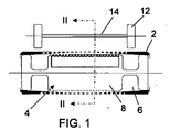
図1乃至4で例証された実施形態の図から明らかなように、本発明の装置は、2つのローラー端部から等しい距離をおいて設けられた1対の周辺溝(6)を含む、ローラー(4)のまわりに巻かれた、穴の開いた、または、液体透過性のゴムの弾性チューブ状のスリーブ(2)を含む。 As is apparent from the illustrations of the embodiments illustrated in FIGS. 1-4, the apparatus of the present invention comprises a pair of peripheral grooves (6) provided at equal distances from the two roller ends. (4) Includes a resilient tubular sleeve (2) of rubber which is wound around, perforated or liquid permeable.
スリーブ(2)は、場合によっては拡張されるエラストマーの1またはそれ以上の層からなるか、あるいは、弾性または非弾性の糸で形成された単一または複数の織物からなり、この場合、糸は、弾性的な織り方に従って織られるか、あるいは、最終的には前者で形成された複合体層でなければならない。スリーブは、いわゆるフラットテーブルのベルトを形成することもでき、従来の製紙機械において、フィードボックス(feed box)に由来する混合物を受け取る。 The sleeve (2) consists of one or more layers of elastomer which are optionally expanded, or consist of a single or a plurality of fabrics formed of elastic or inelastic yarns, where the yarns are Must be woven according to an elastic weave, or ultimately a composite layer formed by the former. The sleeve can also form a so-called flat table belt, which receives a mixture derived from a feed box in a conventional papermaking machine.
スリーブが形成される方法とは無関係に、スリーブは、以下で明らかになる理由で、横方向への伸長方向の厚さが異なる。 Regardless of the manner in which the sleeve is formed, the sleeves have different lateral thicknesses for reasons that will become apparent below.
スリーブ(2)とローラー(4)の間の接続の安定性は、2つのローラー端部まわりでスリーブの縁を折りたたみ、その後、任意の従来のシステムによって、折りたたまれたスリーブの縁を固定することによって保証され、固定は、例えば、スリーブの縁に、伸縮不可能なケーブルを組み入れること、または、バッキングローラー(backing roller)によって、ローラー(4)の端部に付けられるスリーブ(2)のこれらの縁を押さえることを含む。 The stability of the connection between the sleeve (2) and the roller (4) is to fold the edge of the sleeve around the two roller ends and then secure the folded sleeve edge by any conventional system The fixing of the sleeve (2) is secured to the end of the roller (4) by, for example, incorporating a non-stretchable cable at the edge of the sleeve or by a backing roller. Including holding the edges.
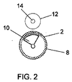
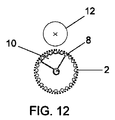
ここで例証される実施形態において、ローラー(4)、または、2つの周辺溝(6)間に位置する少なくともその中央部分(8)はくぼんでおり、完全に穴の開いた円筒状の表面を有する。その内部では、それは、前記中央部分(8)の軸方向の全長に沿って伸長する環状の扇形形状の固定された吸引チャンバー(10)を収容する。 In the embodiment illustrated here, the roller (4), or at least its central part (8) located between the two peripheral grooves (6), is recessed and has a completely perforated cylindrical surface. Have. In its interior, it accommodates an annular fan-shaped fixed suction chamber (10) extending along the entire axial length of the central portion (8).
吸引チャンバー(10)は吸引力の強度を調節するために、別々の部分として形成することができる。 The suction chamber (10) can be formed as a separate part in order to adjust the strength of the suction force.
この吸引チャンバー(10)は吸引ポンプ(図では示されていない)に接続されており、同様に穴をあけられたか、または、空気透過性の、ローラー(4)の中央部分(8)の穴を開けられた表面に面する円筒状の表面を有する。穴の開いた表面の場合、穴部は、例えば、この場合では、吸引力の強度を調節するなどのために、前記穴の開いた表面を形成する、横方向バンドの直径が異なってもよい。 This suction chamber (10) is connected to a suction pump (not shown in the figure) and is similarly perforated or air permeable, a hole in the central part (8) of the roller (4) Having a cylindrical surface facing the opened surface. In the case of a perforated surface, the holes may have different diameters of the transverse bands forming the perforated surface, for example in this case to adjust the strength of the suction force, etc. .
装置は、ローラー(4)の軸に対して平行な軸を備えたシャフトに取り付けられるとともに、ローラー(4)の周辺溝(6)の外側にある際の静止位置(図1および2を参照)と、スリーブ(2)の挟まれた部分と一緒に内部へ部分的に挿入される操作位置との間で平行移動可能(translatable)な一対のローラ(12)を含む。 The device is mounted on a shaft with an axis parallel to the axis of the roller (4) and rests when outside the peripheral groove (6) of the roller (4) (see FIGS. 1 and 2) And a pair of rollers (12) translatable between the sandwiched portion of the sleeve (2) and the operating position partially inserted into the interior.
操作時、すなわち、装置が操作段階にあり、溝(6)にローラー(12)を部分的に入れることによってスリーブ(2)が横方向に延伸する際、3%乃至70%の水含有量を有するとともに、例えば、製紙機械のフロー・ボックスを残した紙混合物からなるか、あるいは、完成して再度湿らせた紙のウェブからなる、柔軟材料のウェブ(16)は、スリーブ(2)の中で最も延伸した部分に落とされる。柔軟な繊維材料のこのウェブが、移動したスリーブ(2)の延伸した部分にある際に、吸引チャンバー(10)によって作成される真空により、前記ウェブ(16)はスリーブのもっとも延伸したその部分と次の部分の両方で、前記スリーブ(2)に付着する。すなわち、ローラー(4)とスリーブ(2)の回転が、ローラー(16)による係合からこの後者のその部分を移動させることによって、スリーブは、延伸していない当初の構造を弾性的に再度とることができる。スリーブ(2)に常に付いたまま柔軟材料のウェブ(16)を維持する吸引効果を伴って、延伸した状態から延伸していない状態へとスリーブ(2)が弾性的に戻ることによって、ウェブの横方向への収縮を引き起こし、したがって、この横方向への収縮に関連付けられる程度まで、最終的なウェブを将来の使用の間、横方向に伸縮可能にさせることは明白である。 During operation, i.e. when the device is in the operating stage and the sleeve (2) is stretched in the transverse direction by partially placing the roller (12) in the groove (6), a water content of 3% to 70% is obtained. A flexible material web (16) comprising, for example, a paper mixture leaving a flow box of a papermaking machine or consisting of a finished and re-moistened web of web is placed in the sleeve (2). It is dropped on the most stretched part. Due to the vacuum created by the suction chamber (10) when this web of flexible fibrous material is in the stretched portion of the moved sleeve (2), the web (16) is separated from the most stretched portion of the sleeve. It adheres to the sleeve (2) both at the next part. That is, the rotation of the roller (4) and the sleeve (2) moves that part of this latter out of engagement by the roller (16), so that the sleeve elastically regains its original unstretched structure. be able to. The elastic return of the sleeve (2) from the stretched state to the unstretched state, with the suction effect of maintaining the web (16) of flexible material always attached to the sleeve (2), It is obvious to cause lateral shrinkage and thus make the final web stretchable laterally for future use to the extent associated with this lateral shrinkage.
スリーブ(2)へのウェブ(16)の付着を容易にするために、スリーブを有利に湿潤にさらすことができる。 In order to facilitate the attachment of the web (16) to the sleeve (2), the sleeve can be advantageously subjected to wetting.
横方向に収縮している柔軟材料のウェブ(16)上で吸引チャンバー(10)によって形成される真空により、ウェブから多くの水分が取り除かれ、乾燥システムの全体的な長さ(乾燥終了(dry end))の減少と、それに関連するエネルギー消費の減少の両方の観点で、乾燥時間と結果として生じる利点を著しく減少させることに注目する。 The vacuum created by the suction chamber (10) on the laterally shrinkable flexible material web (16) removes much moisture from the web and reduces the overall length of the drying system (dry Note that the drying time and the resulting benefits are significantly reduced both in terms of the reduction in end)) and the associated reduction in energy consumption.
ウェブ(16)からの水分除去は、いかなる場合でも、ウェブを高温、好ましくは、縦方向に差次的な温度にさらすことによって、さらに促進されることができる。 Moisture removal from the web (16) can in any case be further facilitated by subjecting the web to elevated temperatures, preferably longitudinally differential temperatures.
横方向に伸縮可能なことに加えて、さらに特定の大きさ(bulk)を示す繊維材料ウェブが必要とされる特定の適用において、吸引チャンバー(10)は、別の吸引チャンバー(図では示されず)によって柔軟材料のウェブ(16)の上に面する。これはエンドレスベルト(2)からウェブ(16)を引き上げないようにチャンバー(10)よりも小さな力を持っていなければならないが、ウェブの厚みを増やすのに十分なものでなければならない。 In certain applications where, in addition to being laterally extensible, a fibrous material web exhibiting a particular bulk is required, the suction chamber (10) is provided with a separate suction chamber (not shown in the figure). ) On the flexible material web (16). This must have a smaller force than the chamber (10) so as not to lift the web (16) from the endless belt (2), but should be sufficient to increase the thickness of the web.
本発明に応じた装置の実際的な実施と、その後の実験的検査において、スリーブ(2)の横方向への延伸のあいだ、スリーブ(2)の特定の部分がローラーの中央部分(8)の円筒状の表面に付き、残りの部分は大気中にあるという事実によって潜在的に引き起こされる、延伸ムラが長さ方向に存在することが注目されてきた。本発明は、異なる厚み、具体的にいえば、部分(8)と接する部分ではより薄く、大気中の部分ではより厚い、ゴムのスリーブ(2)を作ることによって、この欠点を取り除いた。 During practical implementation of the device according to the invention and subsequent experimental inspection, during the lateral stretching of the sleeve (2), a particular part of the sleeve (2) It has been noted that there is longitudinal stretching along the length of the cylinder, potentially caused by the fact that the rest is in the atmosphere. The present invention eliminates this drawback by making a rubber sleeve (2) of different thickness, specifically thinner at the part in contact with the part (8) and thicker at the part in the atmosphere.
このようにして、スリーブは、薄い方の部分(8)に接してその部分にさらに延伸する一方で、厚い方の残りの部分にはさほど延伸しないが、ウェブ(16)の横方向への収縮には直接関係せず、ローラー(12)による大きな圧力に耐えなければならない。 In this way, the sleeve extends further to and contacts the thinner part (8) while not extending much to the remaining thicker part, but the web (16) shrinks laterally. Must be able to withstand the high pressure exerted by the roller (12).
さらに、この段階の間に、前記スリーブが、ローラー(4)の中央部分(8)の表面に沿った接線方向の摺動と、周辺溝(6)と押圧ローラー(presser roller)(12)の縁部での折り目付け加工(creasing)との両方にさらされるという事実によってスリーブ(2)の横方向の延伸ムラが引き起こされるということがわかったため、本発明は、前記スリーブと装置の残りの部分の間で接触するそれらの部分で減摩手段を用いる。 Furthermore, during this stage, the sleeve is tangentially slid along the surface of the central part (8) of the roller (4), the peripheral groove (6) and the pressure roller (12) Since it has been found that the fact that it is exposed to both crease at the edge causes lateral stretching unevenness of the sleeve (2), the present invention provides the sleeve and the rest of the device. Use anti-friction means at those parts that are in contact with each other.
図5および6では、ローラー(4)の中央部分(8)は、円筒状の代わりに凸面外形で形成され、この手法で、前記スリーブの延伸の間、ローラー(4)の中央部分(8)の縁部上のスリーブ(2)に折り目が付くことを防ぐことができる。この実施形態では、2つの押圧ローラー(12)は好ましくは組み合わされることによって、凸面外形のローラーとほぼ相補的な凹面外形を有する単一のローラーにされる。 5 and 6, the central part (8) of the roller (4) is formed with a convex profile instead of being cylindrical, and in this way during the stretching of the sleeve the central part (8) of the roller (4) It is possible to prevent the sleeve (2) on the edge of the crease from being creased. In this embodiment, the two pressure rollers (12) are preferably combined into a single roller having a concave profile that is substantially complementary to the convex profile roller.
図7は、弾性のスリーブ(2)の支持ローラーが、実際には、スリーブ(2)がその間に張られた2つの端部ローラー(18)からなる装置を示している。 FIG. 7 shows a device in which the support roller of the elastic sleeve (2) is actually composed of two end rollers (18) between which the sleeve (2) is stretched.
この場合、柔軟材料のウェブ(10)が位置付けられるその部分では、スリーブ(2)は、ローラー(18)を回転シャフト(20)に近づけることではなく、前記シャフトからそれらを引っ込めることによって、延伸される。 In this case, in that part where the web of flexible material (10) is positioned, the sleeve (2) is stretched by retracting them from the shaft rather than bringing the roller (18) close to the rotating shaft (20). The
これは、複数のボール(24)を円筒状の表面に含む1対の固定ローラーセクター(roller sector)(22)により達成されることができ、該ボールは、ひとたび前記ローラーセクター(22)への干渉が終わると、スリーブ(2)の延伸と停止位置への弾性戻りを促進する。 This can be achieved by a pair of fixed roller sectors (22) comprising a plurality of balls (24) on a cylindrical surface, the balls once reaching the roller sectors (22). When the interference is finished, the extension of the sleeve (2) and the elastic return to the stop position are promoted.
図8の変更形態において、固定された押圧部品(22’)は、固定ローラーセクター(22)とは異なる形状を有するように提供され、特に、それらは、まず、ローラー(18)の回転シャフト(20)に対して垂直に、その後、ローラー(18)の向こう側の前記シャフトとは平行に、外側に延伸する。このように、スリーブ(2)は、柔軟な繊維材料のウェブ(16)に、より大きな支持表面を提示するために、横方向にさらに一段と延伸される。 In the variant of FIG. 8, the fixed pressing parts (22 ′) are provided to have a different shape than the fixed roller sector (22), in particular they are first of all the rotating shaft of the roller (18) ( Perpendicular to 20) and then outwards, parallel to the shaft on the other side of the roller (18). In this way, the sleeve (2) is further stretched in the transverse direction to present a larger support surface to the flexible fibrous material web (16).
図9および10は、スリーブ(2)がローラー(18)の回転シャフト(20)に近づくことで延伸し、その延伸が、支持ボール(28)が設けられた押圧部品(26)によりスリーブに作用することで達成される、装置を示している。特に、これらの押圧部品(26)の長さを適切に選ぶことによって、延伸した状態で留まるスリーブ(2)のその部分の、長手方向で測定される長さが、定義されることができる(図10を参照)。 9 and 10 show that the sleeve (2) stretches as it approaches the rotating shaft (20) of the roller (18), and that stretching acts on the sleeve by the pressing component (26) provided with the support balls (28). The device is achieved by doing. In particular, by appropriately choosing the length of these pressing parts (26), the length measured in the longitudinal direction of that part of the sleeve (2) that remains stretched can be defined ( See FIG.
図11および14はローラー(4)を示し、その中央部分(8)は、延伸の間にスリーブ(2)の摺動を容易にするボールリテーナーから実質的になる。同じ結果は、スリーブ(2)とローラー(4)の間に、グリースまたは他の潤滑性の物質の膜を挟むことによっても明らかに達成可能である。 Figures 11 and 14 show the roller (4), whose central part (8) consists essentially of a ball retainer that facilitates sliding of the sleeve (2) during stretching. The same result can clearly be achieved by sandwiching a film of grease or other lubricious material between the sleeve (2) and the roller (4).
これまで記載された実施形態は、すべて単一の延伸部分を含むが、しかしながら、本発明によれば、柔軟材料のウェブ(16)は1以上の延伸工程にさらされることができる。 The embodiments described so far all include a single stretched portion, however, according to the present invention, the web of flexible material (16) can be subjected to one or more stretching steps.
図15乃至18は、単一のローラー(4)と単一のスリーブ(2)を備えるが、2つの別々のスリーブ延伸ステーションを備えた装置を示す。第1の横方向への圧縮を経た後に第1のステーションを離れるウェブ(16)は、スリーブ(2)が第2の延伸にさらされる前に、スリーブ(2)から明らかに引っ込められなければならず、これが最大限の延伸を達成してウェブ(16)上の第2の横方向への圧縮を実行することができる際に限って、もとに戻ってスリーブと接触しなければならない。 Figures 15 to 18 show an apparatus with a single roller (4) and a single sleeve (2) but with two separate sleeve stretching stations. The web (16) leaving the first station after undergoing a first lateral compression must be clearly retracted from the sleeve (2) before the sleeve (2) is subjected to a second stretch. Rather, it must be brought back into contact with the sleeve only if this achieves maximum stretching and can perform a second lateral compression on the web (16).
同じ結果は図19乃至22に示される異なる装置構造によっても達成することができる。この実施形態は、単一のローラー(4)の回りに巻かれた管状のスリーブ(2)の代わりに、ローラー(4,4’)に張られたベルト(2’)を含む。各々のローラー(4,4’)にはベルト(2’)のためにそれ自体の延伸ステーションが設けられる。 The same results can be achieved with different device structures shown in FIGS. This embodiment includes a belt (2 ') stretched around rollers (4, 4') instead of a tubular sleeve (2) wound around a single roller (4). Each roller (4, 4 ') is provided with its own drawing station for the belt (2').
この場合も再度、先に記載された場合のように、柔軟材料のウェブ(16)は、第1の処理ステーション(treatment station)を離れるとベルト(2’)から明らかに引っ込められなければならず、これが第2のステーションで延伸した後に、再び同じベルト上に位置付けられなければならない。 Again, as previously described, the flexible material web (16) must be clearly retracted from the belt (2 ') upon leaving the first treatment station. Once it has been stretched at the second station, it must be positioned again on the same belt.
繊維材料のウェブ(16)は、ベルトの特徴を改良するために、任意の圧縮工程の前後に、浸潤または適切な物質の追加にさらされることもできる。これにより、この方法を、既に形成されたペーパーウェブに適用することができる。 The web of fibrous material (16) can also be subjected to infiltration or addition of a suitable substance before and after any compression step to improve the characteristics of the belt. This makes it possible to apply this method to an already formed paper web.
先に記載され、例証されたすべての実施形態において、柔軟材料のウェブ(16)の横方向への圧縮は、前記ウェブをたんにスリーブ(2)とベルト(2’)に付けることで行われ、これは、スリーブ(2)またはベルト(2’)が延伸した状態から延伸していない状態まで変化するその部分の吸引チャンバー(10)による真空効果によって引き起こされる。しかしながら、本発明によると、ウェブ(16)が、ウェブ(16)から水分を取り除くために、かつ、形成下で折り目を平らにするために吸引チャンバー(10)とも協働する、外部のフェルト要素(30)によって、スリーブに対してその部分で押圧される場合、スリーブ(2)またはベルト(2’)へのウェブ(16)の付着の効果は増大可能である。ウェブ(16)上のフェルト要素(30)の圧力は、要件に応じて調節することができる。 In all the embodiments described and illustrated above, the lateral compression of the web of flexible material (16) is performed by simply applying said web to the sleeve (2) and the belt (2 '). This is caused by the vacuum effect by the suction chamber (10) in that part of the sleeve (2) or belt (2 ') changing from stretched to unstretched. However, according to the present invention, the external felt element in which the web (16) also cooperates with the suction chamber (10) to remove moisture from the web (16) and to flatten the folds when formed. By (30), the effect of adhesion of the web (16) to the sleeve (2) or belt (2 ′) can be increased when pressed against that portion of the sleeve. The pressure of the felt element (30) on the web (16) can be adjusted according to requirements.
図23は図4に対応しているが、このフェルト要素(30)と一体的に形成されており、フェルト要素は、横方向への延伸の後に停止状態へと戻るその部分において、スリーブ(2)に付いたままである。フェルト要素(30)の存在は、ウェブ(16)のスリーブ(2)への優れた付着と、前記ウェブからの優れた水の抽出とを確約する。 FIG. 23 corresponds to FIG. 4, but is formed integrally with this felt element (30), which felt element in its part (2) returns to the stop state after stretching in the transverse direction. ). The presence of the felt element (30) ensures good adhesion of the web (16) to the sleeve (2) and excellent water extraction from the web.
フェルト要素(30)は、一段と大きな大きさをした、横方向だけでなく縦方向への伸縮が提供される最終生成物を得るために、スリーブ(2)と同じ周速度か、または、低速度で、進められることができる。 The felt element (30) has the same peripheral speed as the sleeve (2) or a lower speed in order to obtain a final product that is larger in size and provided with longitudinal as well as longitudinal stretching. You can proceed.
ウェブ(16)を前方に進ませる傾向があり、その下部表面に作用するエンドレスコンベア(2)の反作用に、および、その上部表面に作用してウェブの前進に反対する押圧要素に、ウェブ(16)をさらす能力は、必ずしもフェルト要素(20)を必要としないが、その代りに、ウェブがエンドレスコンベア(2)の表面に付いたままになるように、前記ウェブ(16)を圧迫する1つまたはそれ以上のローラーによって達成されることができる。 The web (16) tends to move forward, against the reaction of the endless conveyor (2) acting on its lower surface and on the pressing element acting on its upper surface to oppose the web advancement. ) Does not necessarily require the felt element (20), but instead one that compresses the web (16) so that the web remains attached to the surface of the endless conveyor (2). Or can be achieved with more rollers.
とりわけ、フェルト要素は、従来の乾燥圧迫(シュープレス(shoepress))と取り替えられてもよい。 Among other things, the felt elements may be replaced with conventional dry compression (shoepress).
本発明の異なる実施形態では、スリーブ(2)が、弾性材料のみからなる代わりに、弾性のスポンジ材料からなるため、横方向への延伸段階はその厚みの方向への絞りも含む。このようにして、スリーブ(2)の非ストレス状態への弾性的な戻りは、結果として厚みを増やすことにつながり、したがって、ウェブ(16)から水を吸収するという効果をもたらす。 In a different embodiment of the invention, since the sleeve (2) is made of an elastic sponge material instead of only of an elastic material, the transverse drawing step also includes a drawing in the direction of its thickness. In this way, the elastic return of the sleeve (2) to the unstressed state results in an increase in thickness and thus has the effect of absorbing water from the web (16).
図25に示される装置は、スリーブ(2’)がスポンジ材料から形成された中央のバンドのみを有するという点で、図24に示される装置とは異なる。 The device shown in FIG. 25 differs from the device shown in FIG. 24 in that the sleeve (2 ') has only a central band formed from sponge material.
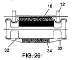
図26で例証された装置は、間に弾性のスポンジスリーブ(34)が挟まれた、2枚の布、または、メッシュ(32)からなるスリーブを示している。これによって、とりわけ、非弾性材料からできた布またはメッシュ(32)を使用することが可能となり、その代わりに、スポンジ材料の固有の弾性を利用することも可能となる。 The device illustrated in FIG. 26 shows a sleeve made of two fabrics or mesh (32) with an elastic sponge sleeve (34) sandwiched therebetween. This makes it possible, inter alia, to use a cloth or mesh (32) made from a non-elastic material, and instead to take advantage of the inherent elasticity of the sponge material.
図27および28で示される装置は、押圧要素が、吸引チャンバー(10)を適切に形作ることによって、延伸にさらされるスリーブ(2)のその部分の伸縮を所望の方法で改良することができるように、配されたリターンローラー(return roller)(38)間に張られたエンドレスベルト(36)からなるという点で、図9および10に示される実施形態と異なる。 The device shown in FIGS. 27 and 28 allows the pressing element to improve the expansion and contraction of that part of the sleeve (2) exposed to stretching in a desired manner by appropriately shaping the suction chamber (10). 9 and 10 in that it consists of an endless belt (36) stretched between return roller (38).
図において、ベルト(36)は平らな断面として示されているが、しかしながら、それらは、明らかに環状の断面の通常のベルトの形状をすることができる。 In the figure, the belts (36) are shown as flat cross-sections, however, they can obviously take the form of a regular belt with an annular cross-section.
図29および30に示される装置は、先の図に関連して既に例証された装置に実質的に相当するが、ローラー(4)内の溝にスリーブ(2)のバンドを挿入することでスリーブ(2)を延伸させる押圧ローラー(12)の代わりに、押圧ローラーは、ローラー(4)の端部にわたってスリーブを外側に折り畳む。この実施形態は、長い軸長さのスリーブ(2)を必要とし、および、ローラー(4)については、ローラー端部を超えて特定の距離にわたって伸長し、かつ、端部に固定されてスリーブ(2)の端部を支持する支持シャフト(40)を必要とする。 The device shown in FIGS. 29 and 30 substantially corresponds to the device already illustrated in connection with the previous figure, but with the sleeve (2) band inserted into the groove in the roller (4), the sleeve Instead of the pressing roller (12) for stretching (2), the pressing roller folds the sleeve outward over the end of the roller (4). This embodiment requires a long axial length sleeve (2) and, for the roller (4), extends over a certain distance beyond the roller end and is fixed to the end of the sleeve ( A support shaft (40) is required to support the end of 2).
このようにして、ローラー(4)の構築はより単純であり、加えて、その側面全体は、支持表面として、柔軟な繊維材料のウェブ(16)に使用することができる。 In this way, the construction of the roller (4) is simpler, in addition, its entire side can be used as a support surface for the flexible fibrous material web (16).
特定の場合には、横方向に伸縮可能であることに加えて、縦方向にも伸縮可能な繊維材料のウェブを得る必要がある。 In certain cases, it is necessary to obtain a web of fibrous material that can be stretched in the longitudinal direction in addition to being stretchable in the lateral direction.
これについて、同じウェブ(16)が、ウェブ(16)の横方向の圧縮を達成するための第1の処理と、その縦方向の圧縮を達成するための第2の処理の、2つの処理に順にさらされることが可能な装置を使用することができる。 In this regard, the same web (16) is divided into two processes: a first process for achieving the lateral compression of the web (16) and a second process for achieving the longitudinal compression thereof. Devices that can be exposed in sequence can be used.
図31はこの装置を概略的に示す。図において、横方向の弾性を有していることに加えて縦方向の弾性も有するスリーブ(2)は、ローラー(4)が回転する速度v1とほぼ等しい速度v2で回転するローラー(42)に対応する位置で分離する小さな部分を除いて、ローラー(4)をほとんど完全に包む。その後、スリーブ(2)は、ローラー(46)で、ローラー(4)と接触するように戻る前に、ローラー(44)の周囲を通過する。 FIG. 31 schematically shows this apparatus. In the figure, the sleeve (2) which has the elasticity in the longitudinal direction in addition to the elasticity in the lateral direction is changed to a roller (42) which rotates at a speed v2 substantially equal to the speed v1 at which the roller (4) rotates. Wrap the roller (4) almost completely, except for a small part that separates in the corresponding position. The sleeve (2) then passes around the roller (44) at the roller (46) before returning to contact the roller (4).
ローラー(44)の回転速度v3は、ローラー(42)の回転速度v2よりも速いが、その一方で、ローラー(46)の回転速度v4は、ローラー(42)の回転速度v2、および、ローラー(4)の回転速度v1とほぼ等しい。 The rotational speed v3 of the roller (44) is faster than the rotational speed v2 of the roller (42), while the rotational speed v4 of the roller (46) is the rotational speed v2 of the roller (42) and the roller ( It is substantially equal to the rotational speed v1 of 4).
この手法において、様々なローラーの速度の差を考慮すると、スリーブ(2)は、ローラー(44)と(46)の間の部分への縦方向の延伸、および、ローラー(44)と(46)の間の部分への弾性的な戻りにさらされる。したがって、柔軟材料のウェブ(16)が、スリーブが横方向に延伸した点で、スリーブ(2)に置かれる場合、横方向の圧縮は前述の理由で起こる。この処理の終了後、ウェブ(16)は、スリーブ(2)が縦方向の延伸にさらされる前に、スリーブ(2)から引っ込められる。 In this approach, taking into account the difference in speed of the various rollers, the sleeve (2) is stretched longitudinally to the portion between the rollers (44) and (46) and the rollers (44) and (46). Exposed to an elastic return to the part between. Thus, when the web of flexible material (16) is placed on the sleeve (2) at the point where the sleeve has been stretched in the transverse direction, lateral compression occurs for the reasons described above. At the end of this process, the web (16) is retracted from the sleeve (2) before the sleeve (2) is subjected to longitudinal stretching.
ローラー(44)に対応する位置で、すなわち、スリーブ(2)が縦方向に延伸された場合、すでに横方向に圧縮したウェブ(16)は、ローラー(44)と(46)の間の次の部分に沿って最初の構造に戻るスリーブ(2)に再度付くように作られることにより、ウェブ(16)の縦方向の圧縮を引き起こす。 In a position corresponding to the roller (44), ie when the sleeve (2) is stretched in the machine direction, the web (16) which has already been compressed in the transverse direction is the next between the rollers (44) and (46). By being made to reattach to the sleeve (2) returning to its original structure along the part, it causes longitudinal compression of the web (16).
該装置に関して、したがって、ウェブ(16)が順にさらされる二重の圧縮処理後に、横方向と縦方向の両方に伸縮可能な繊維材料のウェブを得ることが可能である。 With respect to the device, it is therefore possible to obtain a web of fibrous material that is stretchable in both the transverse and longitudinal directions after a double compression process in which the web (16) is exposed in turn.
弾性ベルト(2)が、横方向の延伸と、おそらくは、縦方向の延伸とにもさらされる、1またはそれ以上の部分を与えるか否かに関係なく、工程の任意の段階で、機械の内部または機械の外部のいずれかで、液体または粉末の物質、あるいは、大気プラズマによる様々な処理にさらされることは、繊維材料のウェブ(16)にとって有利になり得る。とりわけ、再浸潤処理は、噴霧によってであれ、タンクを通過させることによってであれ、提供可能であり、処理液体は、得られる紙材料が現在有している特性にしたがって、水からなるか、着色物質からなるか、または、防水物質などからなる。 Whether the elastic belt (2) provides one or more parts that are also subject to transverse stretching and possibly longitudinal stretching, at any stage of the process, the interior of the machine It may be advantageous for the web (16) of fiber material to be exposed to various treatments with liquid or powdered substances, or atmospheric plasma, either outside of the machine. In particular, a re-infiltration treatment can be provided, whether by spraying or by passing through a tank, and the treatment liquid consists of water or is colored according to the properties that the resulting paper material currently has. It consists of a substance or a waterproof substance.
本発明の方法を実施する装置は、例えば、拡大する折り目の特性を利用することにより縦方向に延伸可能で、かつ、この方向における繊維材料の伸縮性の特徴を利用することにより横方向にも延伸可能な、繊維材料のウェブを獲得することについて、米国第2624245号と米国第6024832号に記載された従来の縮み(creping))および圧縮用の機械と、有利に組み合わされ得る。同様に、該装置は、様々な用途に最もふさわしい特徴を示す、任意の種類の結合したウェブを形成するために、結合用の機械と有利に組み合わされ得る。 An apparatus for carrying out the method of the present invention can be stretched in the longitudinal direction by utilizing, for example, the characteristics of expanding folds, and also in the lateral direction by utilizing the stretch characteristics of the fiber material in this direction. For obtaining a stretchable, web of fibrous material, it can be advantageously combined with the conventional creping and compression machines described in US Pat. No. 2,624,245 and US Pat. No. 6,024,832. Similarly, the device can be advantageously combined with a bonding machine to form any type of bonded web that exhibits features most appropriate for various applications.
Claims (15)
前記方法は、
縦軸から縁部まで厚みが増している、弾性材料の、液体透過性のエンドレスコンベアベルト(2,2’)を、少なくとも1つの局所的な横方向への延伸操作にさらし、延伸は、少なくとも1つの縦方向のバンドを、前記バンドが通常摺動する表面から一時的に引っ込めること、および、延伸状態で、少なくとも1つの支持部材(4,4’,10)の表面の少なくとも一部と接触したまま前記バンドを維持することによって達成され、
前記方法は、
横方向に延伸した弾性材料の前記コンベアベルト(2,2’)の部分に対して、3重量%から70重量%の液体含有量を有する柔軟な繊維材料のウェブ(16)を堆積させ、
前記ウェブ(16)の横方向への圧縮と、それと同時の液体の部分的な除去を引き起こすために、元々の構造に戻る間、真空効果によって、柔軟な繊維材料の前記ウェブ(16)を、弾性材料の前記コンベアベルト(2,2’)に付いたまま維持する、方法。 A method for forming a web of fibrous material that is stretchable in a transverse direction, comprising:
The method
Subjecting the elastic material, liquid permeable endless conveyor belt (2, 2 '), increasing in thickness from the longitudinal axis to the edge, to at least one local transverse stretching operation, the stretching is at least Temporarily retracting one longitudinal band from the surface on which the band normally slides, and in contact with at least a portion of the surface of at least one support member (4, 4 ', 10) Achieved by keeping the band as it is,
The method
Depositing a web (16) of flexible fibrous material having a liquid content of 3% to 70% by weight on the part of said conveyor belt (2,2 ') of elastic material stretched in the transverse direction;
In order to cause lateral compression of the web (16) and concomitant partial removal of the liquid, the web (16) of flexible fibrous material is brought into contact with the original structure by a vacuum effect while returning to its original structure. A method of keeping the conveyor belt (2, 2 ') of elastic material attached.
前記周辺溝(6)を覆う2つの周辺バンドを、前記溝に一時的に挿入することによって、前記スリーブ(2)の横方向への延伸を引き起こす、請求項1に記載の方法。 Conveying a sleeve (2) of elastic material mounted on a support member comprising a substantially rigid material roller (4) having a perforated outer surface and provided with a pair of peripheral grooves (6) Used as a belt, the sleeve (2) being fixed at its edges to the end of the roller (4), and
The method according to claim 1, wherein two peripheral bands covering the peripheral groove (6) are caused to cause the sleeve (2) to stretch in the lateral direction by temporarily inserting into the groove.
前記間を開けて配されたローラー(18)によって定義される周辺の空洞を覆う中央のバンドを、前記空洞から一時的に引っ込めることによって、弾性材料の前記スリーブ(2)の横方向への延伸を引き起こす、請求項1に記載の方法。 A sleeve (2) of elastic material attached on a support member, consisting of rollers (18) arranged with a gap between a pair, is used as an endless conveyor belt,
Stretching the elastic material in the transverse direction of the sleeve (2) by temporarily retracting a central band covering the peripheral cavity defined by the spaced apart rollers (18) from the cavity The method of claim 1, wherein
前記支持ローラー(4)の軸に対して平行な軸と、軸長さよりも長い離間した距離とを有し、前記ローラーを超えて突出する前記スリーブの部分が軸に到達するように、前記軸に対して垂直に平行移動するように作られた、一対の押圧ローラー(12)によって、弾性材料の前記スリーブ(2)の横方向への延伸を引き起こす、請求項2に記載の方法。 A sleeve of elastic material mounted on a support roller (4) having an axial length shorter than the axial length of the sleeve (2) fixed at the end to the external extension (40) of the rotating shaft of the roller (2) is used as an endless conveyor belt,
The shaft having an axis parallel to the axis of the support roller (4) and a spaced distance longer than the shaft length, so that the portion of the sleeve protruding beyond the roller reaches the shaft. 3. A method according to claim 2 , wherein a pair of pressing rollers (12) made to translate perpendicularly with respect to each other cause the elastic material to stretch in the transverse direction of the sleeve (2).
前記装置は、
縦軸から縁部に向かって厚みが増加している、弾性材料の、流体透過性のエンドレスコンベアベルト(2,2’)、
少なくとも1つの縦軸バンドが通常摺動する表面から、前記縦軸バンドを引っ込めた後に、前記エンドレスコンベアベルト(2,2’)の局所的な横方向への延伸を引き起こすための、および、延伸した状態において、少なくとも1つの支持部材(4,4’)の表面の少なくとも一部に付いたまま、前記ベルトを維持するための手段、
エンドレスコンベアベルトの横方向に延伸する部分上に、柔軟な繊維材料の前記ウェブ(16)を堆積させるための手段、
前記ベルトの元々の構造への弾性的な戻りの間、前記ベルトに付いたまま柔軟な繊維材料の前記ウェブを維持するために、この手法で、柔軟な繊維材料の前記ウェブの横方向への圧縮と、それと同時にそこからの液体の部分的な除去を引き起こすために、前記エンドレスコンベアベルト(2,2’)を介して作用する、少なくとも1つの固定された真空ソース(10)、
を含む、装置。 An apparatus for producing a transversely stretchable fiber material from a flexible fiber material web (16) having a water content of 3% to 70%, comprising:
The device is
An elastic material, fluid permeable endless conveyor belt (2, 2 '), increasing in thickness from the vertical axis towards the edge,
To cause local lateral stretching of the endless conveyor belt (2, 2 ') after retracting the longitudinal band from a surface on which at least one longitudinal band normally slides, and stretching Means for maintaining the belt while still attached to at least part of the surface of the at least one support member (4, 4 ')
Means for depositing said web (16) of flexible fibrous material on a laterally extending portion of an endless conveyor belt;
In order to maintain the web of flexible fibrous material while remaining on the belt during the elastic return to the original structure of the belt, this approach allows the flexible fibrous material to be transverse to the web. At least one fixed vacuum source (10) acting via said endless conveyor belt (2, 2 ') to cause compression and at the same time partial removal of the liquid therefrom;
Including the device.
シャフト(14)の軸に対して垂直に平行移動可能な、前記シャフト(14)に取り付けられた一対の押圧ローラー(12)であって、前記押圧ローラーを前記周辺溝(6)に挿入する、および、この手法で、前記溝を覆う前記スリーブの部分を前記溝に引き込む、一対の押圧ローラー(12)をさらに含む、請求項12に記載の装置。 Endless conveyor comprising a sleeve (2) wound around a substantially rigid material roller (4, 4 ') having a perforated outer surface and provided with a pair of peripheral grooves (6) Including a belt, the sleeve being fixed to the end of the roller (4, 4 ') at both edges,
A pair of pressing rollers (12) attached to the shaft (14) capable of translating perpendicularly to the axis of the shaft (14), the pressing rollers being inserted into the peripheral groove (6); The apparatus of claim 12, further comprising a pair of pressing rollers (12) that, in this manner, pulls a portion of the sleeve covering the groove into the groove.
挿入によって前記周辺溝に入るという意味で作用する、および、この手法で前記スリーブ(2)の中央バンドを溝に引き込む、一対の押圧ローラー(12)をさらに含む、請求項12又は13に記載の装置。 An endless conveyor belt comprising a sleeve (2) wound around a substantially rigid material roller (4) with a peripheral groove in the middle, said sleeve being at both edges of said roller (4) Fixed to the end, and
14. A pair of pressure rollers (12) according to claim 12 or 13 , further comprising a pair of pressing rollers (12) which act in the sense of entering the peripheral groove by insertion and which draw the central band of the sleeve (2) into the groove in this manner. apparatus.
Applications Claiming Priority (3)
| Application Number | Priority Date | Filing Date | Title |
|---|---|---|---|
| ITVE2010A000029 | 2010-06-01 | ||
| ITVE2010A000029A IT1400457B1 (en) | 2010-06-01 | 2010-06-01 | METHOD OF REALIZATION OF STRETCHES OF FIBROUS MATERIAL EXTENSIBLE TRANSVERSALLY, IN PARTICULAR OF PAPER RIBBONS, AND EQUIPMENT TO CARRY OUT THE METHOD. |
| PCT/IB2011/001193 WO2011151705A2 (en) | 2010-06-01 | 2011-05-31 | Method for forming webs of transversely extensible fibrous material, in particular paper webs, and apparatus for implementing the method |
Publications (3)
| Publication Number | Publication Date |
|---|---|
| JP2013533132A JP2013533132A (en) | 2013-08-22 |
| JP2013533132A5 JP2013533132A5 (en) | 2014-07-17 |
| JP5756517B2 true JP5756517B2 (en) | 2015-07-29 |
Family
ID=43304865
Family Applications (1)
| Application Number | Title | Priority Date | Filing Date |
|---|---|---|---|
| JP2013512997A Active JP5756517B2 (en) | 2010-06-01 | 2011-05-31 | Method of forming a web of fibrous material, in particular a paper web, which can be stretched in the transverse direction, and an apparatus for carrying out the method |
Country Status (8)
| Country | Link |
|---|---|
| US (1) | US8603299B2 (en) |
| EP (1) | EP2576201B8 (en) |
| JP (1) | JP5756517B2 (en) |
| CN (1) | CN102883876B (en) |
| BR (1) | BR112012026669B1 (en) |
| IT (1) | IT1400457B1 (en) |
| PL (1) | PL2576201T3 (en) |
| WO (1) | WO2011151705A2 (en) |
Families Citing this family (7)
| Publication number | Priority date | Publication date | Assignee | Title |
|---|---|---|---|---|
| ITVE20110071A1 (en) * | 2011-10-27 | 2013-04-28 | Giorgio Trani | METHOD TO MODIFY THE PHYSICAL AND / OR CHEMICAL CHARACTERISTICS OF A FIBER RIBBON AND EQUIPMENT TO IMPLEMENT THE METHOD. |
| ITVE20110077A1 (en) * | 2011-11-30 | 2013-05-31 | Giorgio Trani | MULTIFUNCTION APPARATUS FOR PROCESSING RIBBONS OF FIBROUS AND / OR PLASMAABLE MATERIAL. |
| SG11201704746TA (en) | 2014-12-23 | 2017-07-28 | 3M Innovative Properties Co | Edge contact substrate transport method and apparatus |
| IT201700019934A1 (en) * | 2017-02-22 | 2018-08-22 | Giorgio Trani | Method and apparatus for producing a web of stretchable fibrous material. |
| DE102020114602A1 (en) * | 2020-06-02 | 2021-12-02 | Voith Patent Gmbh | PROCESS AND MACHINE FOR MANUFACTURING CROSS-DIRECTIONAL EXTENSIBLE FIBER WEB |
| DE102021118165B4 (en) | 2021-07-14 | 2023-06-29 | Voith Patent Gmbh | roller arrangement |
| DE102021122688A1 (en) * | 2021-09-02 | 2023-03-02 | Voith Patent Gmbh | Process and machine for producing a fibrous web |
Family Cites Families (8)
| Publication number | Priority date | Publication date | Assignee | Title |
|---|---|---|---|---|
| US2535734A (en) * | 1945-01-08 | 1950-12-26 | Grettve Karl Einar Lage | Apparatus for creping paper and other crepable foils |
| BE516549A (en) | 1952-06-11 | |||
| IT1287656B1 (en) | 1995-04-07 | 1998-08-06 | Cartiere Cariolaro Spa | PROCEDURE FOR THE PRODUCTION OF RELEVANT PAPER AND PLANT TO PERFORM THE PROCEDURE |
| SE504820C2 (en) * | 1995-09-08 | 1997-04-28 | Bertil Wahren | Conveyor |
| US5942085A (en) * | 1997-12-22 | 1999-08-24 | The Procter & Gamble Company | Process for producing creped paper products |
| DE19935481A1 (en) * | 1999-07-28 | 2001-02-08 | Voith Paper Patent Gmbh | Method and device for producing a fibrous web |
| JP3095465U (en) * | 2003-01-24 | 2003-07-31 | 文達 謝 | Structure of dewatering roller for papermaking |
| ITVE20080066A1 (en) * | 2008-08-07 | 2010-02-08 | Giorgio Trani | METHOD OF REALIZATION OF STRETCHES OF FIBROUS MATERIAL EXTENSIBLE, TRANSVERSALLY, IN PARTICULAR PAPER, AND EQUIPMENT TO CARRY OUT THE METHOD. |
-
2010
- 2010-06-01 IT ITVE2010A000029A patent/IT1400457B1/en active
-
2011
- 2011-05-31 CN CN201180022400.7A patent/CN102883876B/en active Active
- 2011-05-31 WO PCT/IB2011/001193 patent/WO2011151705A2/en active Application Filing
- 2011-05-31 EP EP11735531.3A patent/EP2576201B8/en active Active
- 2011-05-31 BR BR112012026669-1A patent/BR112012026669B1/en active IP Right Grant
- 2011-05-31 PL PL11735531T patent/PL2576201T3/en unknown
- 2011-05-31 US US13/638,471 patent/US8603299B2/en active Active
- 2011-05-31 JP JP2013512997A patent/JP5756517B2/en active Active
Also Published As
| Publication number | Publication date |
|---|---|
| US8603299B2 (en) | 2013-12-10 |
| EP2576201B8 (en) | 2014-12-24 |
| EP2576201A2 (en) | 2013-04-10 |
| BR112012026669A2 (en) | 2017-12-12 |
| EP2576201B1 (en) | 2014-07-02 |
| CN102883876B (en) | 2015-02-11 |
| PL2576201T3 (en) | 2014-12-31 |
| CN102883876A (en) | 2013-01-16 |
| WO2011151705A3 (en) | 2012-03-22 |
| BR112012026669B1 (en) | 2020-02-11 |
| ITVE20100029A1 (en) | 2011-12-17 |
| US20130037231A1 (en) | 2013-02-14 |
| IT1400457B1 (en) | 2013-05-31 |
| JP2013533132A (en) | 2013-08-22 |
| WO2011151705A2 (en) | 2011-12-08 |
Similar Documents
| Publication | Publication Date | Title |
|---|---|---|
| JP5756517B2 (en) | Method of forming a web of fibrous material, in particular a paper web, which can be stretched in the transverse direction, and an apparatus for carrying out the method | |
| KR0130065B1 (en) | Apparatus for transferring a paper wib | |
| JP2014523977A (en) | Method and apparatus for producing a paper fibrous tissue web | |
| JP2013533132A5 (en) | ||
| KR100199708B1 (en) | Paper processing belt coated with polymer resin and method of seam closure therefrom | |
| JPH09504202A (en) | Method and apparatus for joining a stretched elastic member with a moving support web | |
| CN1642725A (en) | Method and apparatus for making a creped tissue with improved tactile qualities while improving handling of the web | |
| US2535734A (en) | Apparatus for creping paper and other crepable foils | |
| ES2058671T3 (en) | FLEXIBLE, WATERPROOF BANDS MANUFACTURING PROCEDURE. | |
| KR101401743B1 (en) | Improvements in or relating to rolls | |
| JP3978211B2 (en) | Paper machine smoothing press and paper machine press with smoothing press | |
| JP3160397B2 (en) | Roll with separate skin and roll core | |
| KR100372009B1 (en) | Apparatus of adhering textile in a two-fold way and method thereof | |
| CN107650455A (en) | Composite membrane and its composite structure and combination process with texture structure | |
| KR100848036B1 (en) | Breathable elastic cushion and water-repellent spandex lamination sheet and a manufacturing method thereof | |
| CN103998226A (en) | Multifunction apparatus for processing webs of fibrous and/or pliable material | |
| CN104203173A (en) | Absorbent article manufacturing device | |
| CN107914507A (en) | A kind of roll paper processing unit (plant) | |
| JP3795002B2 (en) | Elastic sleeve for shoe press, method for producing elastic sleeve for shoe press, and shoe press roll | |
| JP2005154145A5 (en) | ||
| GB2477157A (en) | A de-watering or squeeze roll and related apparatus | |
| WO2015171043A1 (en) | A shoe press and a machine for producing laminated paperboard | |
| EP2681042A1 (en) | Method for forming a web of transversely compacted fibrous material with voluminosity and extensibility increase, and apparatus for implementing the method | |
| CH197551A (en) | A method for shrinking a fabric, and apparatus for carrying out this method. | |
| US20040234716A1 (en) | Method for forming endless belt |
Legal Events
| Date | Code | Title | Description |
|---|---|---|---|
| A521 | Request for written amendment filed |
Free format text: JAPANESE INTERMEDIATE CODE: A523 Effective date: 20140529 |
|
| A621 | Written request for application examination |
Free format text: JAPANESE INTERMEDIATE CODE: A621 Effective date: 20140530 |
|
| A977 | Report on retrieval |
Free format text: JAPANESE INTERMEDIATE CODE: A971007 Effective date: 20141208 |
|
| A131 | Notification of reasons for refusal |
Free format text: JAPANESE INTERMEDIATE CODE: A131 Effective date: 20150106 |
|
| A521 | Request for written amendment filed |
Free format text: JAPANESE INTERMEDIATE CODE: A523 Effective date: 20150312 |
|
| TRDD | Decision of grant or rejection written | ||
| A01 | Written decision to grant a patent or to grant a registration (utility model) |
Free format text: JAPANESE INTERMEDIATE CODE: A01 Effective date: 20150511 |
|
| A61 | First payment of annual fees (during grant procedure) |
Free format text: JAPANESE INTERMEDIATE CODE: A61 Effective date: 20150529 |
|
| R150 | Certificate of patent or registration of utility model |
Ref document number: 5756517 Country of ref document: JP Free format text: JAPANESE INTERMEDIATE CODE: R150 |
|
| R250 | Receipt of annual fees |
Free format text: JAPANESE INTERMEDIATE CODE: R250 |
|
| R250 | Receipt of annual fees |
Free format text: JAPANESE INTERMEDIATE CODE: R250 |
|
| R250 | Receipt of annual fees |
Free format text: JAPANESE INTERMEDIATE CODE: R250 |
|
| R250 | Receipt of annual fees |
Free format text: JAPANESE INTERMEDIATE CODE: R250 |
|
| R250 | Receipt of annual fees |
Free format text: JAPANESE INTERMEDIATE CODE: R250 |
|
| R250 | Receipt of annual fees |
Free format text: JAPANESE INTERMEDIATE CODE: R250 |