JP5756089B2 - Applicator tool assembly and applicator tool suitable therefor - Google Patents
Applicator tool assembly and applicator tool suitable therefor Download PDFInfo
- Publication number
- JP5756089B2 JP5756089B2 JP2012510170A JP2012510170A JP5756089B2 JP 5756089 B2 JP5756089 B2 JP 5756089B2 JP 2012510170 A JP2012510170 A JP 2012510170A JP 2012510170 A JP2012510170 A JP 2012510170A JP 5756089 B2 JP5756089 B2 JP 5756089B2
- Authority
- JP
- Japan
- Prior art keywords
- applicator tool
- applicator
- collective
- cap
- assembly
- Prior art date
- Legal status (The legal status is an assumption and is not a legal conclusion. Google has not performed a legal analysis and makes no representation as to the accuracy of the status listed.)
- Active
Links
Images






Classifications
-
- B—PERFORMING OPERATIONS; TRANSPORTING
- B43—WRITING OR DRAWING IMPLEMENTS; BUREAU ACCESSORIES
- B43K—IMPLEMENTS FOR WRITING OR DRAWING
- B43K25/00—Attaching writing implements to wearing apparel or objects involving constructional changes of the implements
-
- A—HUMAN NECESSITIES
- A45—HAND OR TRAVELLING ARTICLES
- A45F—TRAVELLING OR CAMP EQUIPMENT: SACKS OR PACKS CARRIED ON THE BODY
- A45F5/00—Holders or carriers for hand articles; Holders or carriers for use while travelling or camping
- A45F5/1566—Holders or carriers for tubular, rod-shaped articles, e.g. batons
-
- B—PERFORMING OPERATIONS; TRANSPORTING
- B43—WRITING OR DRAWING IMPLEMENTS; BUREAU ACCESSORIES
- B43K—IMPLEMENTS FOR WRITING OR DRAWING
- B43K23/00—Holders or connectors for writing implements; Means for protecting the writing-points
- B43K23/06—Means for connecting two or more writing implements
-
- B—PERFORMING OPERATIONS; TRANSPORTING
- B43—WRITING OR DRAWING IMPLEMENTS; BUREAU ACCESSORIES
- B43K—IMPLEMENTS FOR WRITING OR DRAWING
- B43K23/00—Holders or connectors for writing implements; Means for protecting the writing-points
- B43K23/08—Protecting means, e.g. caps
-
- A—HUMAN NECESSITIES
- A45—HAND OR TRAVELLING ARTICLES
- A45C—PURSES; LUGGAGE; HAND CARRIED BAGS
- A45C11/00—Receptacles for purposes not provided for in groups A45C1/00-A45C9/00
- A45C11/34—Pencil boxes; Pencil etuis or the like
-
- A—HUMAN NECESSITIES
- A45—HAND OR TRAVELLING ARTICLES
- A45D—HAIRDRESSING OR SHAVING EQUIPMENT; EQUIPMENT FOR COSMETICS OR COSMETIC TREATMENTS, e.g. FOR MANICURING OR PEDICURING
- A45D40/00—Casings or accessories specially adapted for storing or handling solid or pasty toiletry or cosmetic substances, e.g. shaving soaps or lipsticks
- A45D2040/0006—Accessories
Landscapes
- Coating Apparatus (AREA)
- Mechanical Pencils And Projecting And Retracting Systems Therefor, And Multi-System Writing Instruments (AREA)
- Pens And Brushes (AREA)
Description
本発明は、請求項1に述べられるようなアプリケータ用具アセンブリ、アプリケータ用具アセンブリでの使用に適する請求項17に述べられるようなアプリケータ用具、及び請求項18にしたがう、アプリケータ用具アセンブリのための少なくとも1つの集合素子及び複数のアプリケータ用具を含む、パーツキット、特にセールスユニットに関する。
The present invention relates to an applicator tool assembly as described in
アプリケータ用具は、例えば、筆記ペンまたはドローイングペンまたはクレヨン等の形態で知られている。アプリケータ用具は通常、細長く、先細りであり、丸いか、楕円形かまたは多角形の断面をもつ。既知の筆記用具を用いる場合、筆記用具は個々の使用の間は支持面、例えば机の上におかれることが多く、その後、改めて用いるために掴まれて支持面から取り上げられる。筆記用具の断面がほぼ丸いため、クリップがなければ筆記用具は傾斜面上に置かれた場合に制御不能な態様で転がっていってしまいがちであることが知られている。したがって、多くの筆記用具には、筆記用具の転がりを防止するための特別な転がり止め素子がある。アプリケータ用具、特に筆記用具は、クリップまたは転がり止め素子を用いることで置かれた場所に留まる。しかし、用具の転がりを防止するためのそのような手段は、上述した転がり止め素子のような、そうした目的のためだけの追加の素子が用いられる場合には特に、筆記用具の製造を複雑にし、製造コストを高める。 The applicator tool is known, for example, in the form of a writing pen, a drawing pen or a crayon. The applicator tool is usually elongated and tapered and has a round, oval or polygonal cross section. When using a known writing instrument, the writing instrument is often placed on a support surface, such as a desk, between individual uses, and is then grabbed and taken up from the support surface for further use. It is known that since the writing instrument has a substantially round cross section, the writing instrument tends to roll in an uncontrollable manner when placed on an inclined surface without a clip. Therefore, many writing tools have a special anti-roll element for preventing the writing tool from rolling. Applicator tools, especially writing tools, stay in place by using clips or anti-roll elements. However, such means for preventing the rolling of the tool complicate the manufacture of the writing instrument, especially when additional elements are used only for such purposes, such as the anti-rolling element described above, Increase manufacturing costs.
既知の筆記用具にともなう別の欠点は、作業手順において多くの様々な筆記用具またはドローイングクレヨンが必要なユーザが筆記用具を保護して乾燥を防ぐために備えられたキャップで個々の筆記用具を、個々の使用の間毎には、閉封しないことである。そのような封止キャップは通常、アプリケータ部材に気密に蓋をするため及び/またはアプリケータ部材を機械的影響から保護するために、作動端、すなわちアプリケータ用具の書付物質を塗布または転写するための部材をもつ先端に、嵌め合わされるかまたはねじ込まれる。アプリケータ用具を用いるため、キャップが作動端の反対側の非作動端にも嵌め合わされることができ、キャップ及び/または非作動端がそのように適合されていれば、封止キャップを外して非作動端に被せることができる。男性または女性のユーザが作業している場所を急に離れなければならない場合、蓋がされていない筆記用具及び/またはそのキャップが何となくそのまま残されることがおこり得る。これにより、筆記用具が乾燥してしまうかまたは干からびるリスクが生じる。さらに、ごろごろ動く筆記用具を急いで取り上げて持ち歩くには努力が必要である。 Another drawback associated with known writing instruments is that individual writing instruments can be individually fitted with caps to protect the writing utensils and prevent them from drying out by users who require many different writing utensils or drawing crayons in their work procedures. Do not seal between each use. Such sealing caps typically apply or transfer the working material, i.e. the writing material of the applicator tool, in order to hermetically cover the applicator member and / or to protect the applicator member from mechanical influences. It is fitted or screwed into a tip with a member for it. Because the applicator tool is used, the cap can also be fitted to the non-working end opposite the working end, and if the cap and / or non-working end is so fitted, the sealing cap can be removed. Can be placed over the non-working end. If a male or female user has to leave the place of work suddenly, it can happen that the writing instrument and / or its cap that is not covered is left untouched. This creates a risk that the writing instrument will dry or dry out. In addition, it takes effort to quickly pick up and move a moving writing instrument.
さらに、既知の筆記用具は、その形状寸法のため、取り上げることが困難であることが多い。筆記用具は非常に狭いかまたは小さい断面を有することが多く、このため、横におかれていた筆記用具を取り上げることは一般にそれほど困難ではないが、筆記用具がおかれている表面から測った、人間の指球で掴むことができる筆記用具の表面、すなわち筆記用具の掴み得る表面の高さが指球の平均高さより小さいばあいがほとんどであるから、それほど容易でもない。ここで、「指球高」は本文脈において、それぞれの指の内側の端にある末端感覚球に対する中心の、指先に対する、または筆記用具がおかれているか同じ指の指先がかかる、表面に対する、間隔を表す。例えば筆記ペン及び/または色鉛筆またはペンの形態の、複数の筆記用具に関わる上述の使用状況において、筆記用具は、開けた状態で、すなわち保護キャップ無しで、おかれることが多い。したがって、ペンが置かれている表面からペンの1つを取り上げるための上述の動作において、閉められていない筆記用具先端のその表面への接触がおこり得る。この場合、一方では筆記用具がおかれていた表面がペンまたは鉛筆で汚されることになり、他方では、例えばシャープペンまたはドローイングフェルトペンまたは精細フェルトスティッククレヨンの先端のような、繊細な筆記用またはドローイング用のペン先の場合、筆記用またはドローイング用のペン先が、おかれていた表面との接触によって損傷を受けるかまたは破壊されることがあり得る。 Furthermore, known writing instruments are often difficult to pick up due to their geometry. Writing instruments often have very narrow or small cross-sections, so it is generally not so difficult to pick up a writing instrument that was laid down, but measured from the surface on which the writing instrument is placed, Since the surface of the writing instrument that can be grasped by a human finger ball, that is, the height of the surface of the writing instrument that can be grasped is almost smaller than the average height of the finger ball, it is not so easy. Here, “fingerball height” in this context is centered on the distal sensory sphere at the inner edge of each finger, on the fingertip, or on the surface on which the writing tool is placed or the same fingertip is applied. Represents an interval. In the use situations described above involving a plurality of writing instruments, for example in the form of a writing pen and / or colored pencil or pen, the writing instrument is often left open, i.e. without a protective cap. Thus, in the above-described operation for picking one of the pens from the surface on which the pen is placed, contact of the unclosed writing instrument tip to that surface can occur. In this case, on the one hand, the surface on which the writing instrument was placed will be soiled with a pen or pencil, and on the other hand, for delicate writing or for example the tip of a mechanical pen or a drawing felt pen or a fine felt stick crayon. In the case of a drawing nib, the writing or drawing nib can be damaged or destroyed by contact with the surface on which it was placed.
上述した封止キャップに関し、そのようなキャップが誤って飲み込まれた場合に呼吸気の交換を可能にし続けるため、キャップが軸方向に少なくとも1つの小さな貫通開口を有するべきであることにも言及しておかなければならない。そのような開口の位置及び大きさは、「14歳までの子供の使用が想定される筆記用具及びマーキング用具のためのキャップ:安全要件(Caps for writing and marking instruments intended for use by children up to 14 years of age; Safety requirements)」に関する、ISO標準11540の主題である。貫通開口を設けることでキャップの飲み込みに関するリスクは低減できるが、それにもかかわらず、そのような場合に、キャップの貫通開口が詰まって役に立たなくなるリスクが残っている。 With respect to the sealing cap described above, it is also noted that the cap should have at least one small through-opening in the axial direction in order to continue to allow breathing exchange if such a cap is accidentally swallowed. I have to keep it. The location and size of such openings are described in “Caps for writing and marking instruments intended for use by children up to 14”. is the subject of ISO standard 11540. Providing the through-opening can reduce the risk of swallowing the cap, but nevertheless, there remains a risk that the cap's through-opening will become clogged and unusable.
本発明の課題は上述した欠点の内の少なくとも1つを無くすかまたは少なくとも軽減することにある。特に、本発明の課題は、複数の筆記用具を、迅速に、容易にかつ安全に、一緒にしておくことができ、したがっていつでも迅速に他所に移すかまたは片付けることができる、実現可能な態様を提供することである。 The object of the present invention is to eliminate or at least reduce at least one of the above-mentioned drawbacks. In particular, the object of the present invention is to provide a feasible aspect in which a plurality of writing instruments can be kept together quickly, easily and safely and thus can be quickly moved or cleared away at any time. Is to provide.
本発明にしたがう解決策は、特許請求項1の特徴を有するアプリケータ用具アセンブリ、特許請求項17に述べられるようなアプリケータ用具アセンブリとの使用に適するアプリケータ用具、及び、特許請求項18にしたがう、アプリケータ用具アセンブリのための少なくとも1つの集合素子及び複数のアプリケータ用具を含むパーツキット、特にセールスユニットを提供する。有益な構成及び発展形は従属請求項に挙げられる。
A solution according to the invention consists in an applicator tool assembly having the features of
本文脈において、「アプリケータ用具」が、鉛筆、色鉛筆及びクレヨン、シャープペンシル、油性マジックペン、ガラス鉛筆、万年筆、ボールペン、ローラーポイントペン、ゲルインクペン、フェルトペン、ファイバペン、油性マーカー、テキストマーカー及び蛍光マーカー等だけしか包含しないと解されるべきではないことに注意すべきである。本発明にしたがうアプリケータ用具は原理的に、網羅はしていないが、例えば、メーキャップペンシル、アイシャドウまたはアイライナー、パウダースティック、口紅または医用リップスティック等の内の1つのような、化粧用及び/または医用物質を塗るためのペン様用具とすることもできる。構造及び機能に関して当業者にはこれらのアプリケータ用具は基本的に既知であるから、本発明の理解に必要ではない詳細が本明細書に含まれることはない。 In this context, "applicator tool" includes pencils, colored pencils and crayons, mechanical pencils, oily magic pens, glass pencils, fountain pens, ballpoint pens, roller point pens, gel ink pens, felt pens, fiber pens, oily markers, text markers and It should be noted that it should not be construed as including only fluorescent markers and the like. Applicator devices according to the present invention are in principle not exhaustive, but may be used for cosmetic and cosmetic applications such as makeup pencils, eyeshadows or eyeliners, powder sticks, lipsticks or medical lipsticks etc. It can also be a pen-like device for applying medical substances. Since these applicator devices are basically known to those skilled in the art in terms of structure and function, details not necessary for an understanding of the present invention are not included herein.
本発明の第1の態様は、実質的に集合素子及び少なくとも2つのアプリケータ用具を含む、アプリケータ用具アセンブリに関する。アプリケータ用具は、アプリケータ用具の長手方向及び少なくとも1つの作動端とおそらくは非作動端によって実質的に決定される主軸を特徴とする。これらの端の内の1つの領域において、本発明にしたがうアプリケータ用具は少なくとも1つの連結素子を有する。集合素子はそれぞれのアプリケータ用具とそれぞれの連結素子を用いて連結される。 A first aspect of the invention relates to an applicator tool assembly that substantially includes an assembly element and at least two applicator tools. The applicator tool is characterized by a major axis substantially determined by the longitudinal direction of the applicator tool and at least one working end and possibly a non-working end. In one region of these ends, the applicator device according to the invention has at least one connecting element. The collective elements are connected to each applicator tool using a respective connecting element.
複数のアプリケータ用具を本発明にしたがうアプリケータ用具アセンブリによって容易にかつ確実に一緒にすることができる。連結素子がアプリケータ用具のキャップである構造の場合には特に、キャップを見失うかまたはキャップが置かれた場所にキャップを置き忘れる危険が著しく減じられる。さらに、十分な大きさにつくられた集合素子に確保されたキャップの飲み込みはほとんど完全に無くすことができる。 Multiple applicator tools can be easily and reliably brought together by an applicator tool assembly according to the present invention. Especially in the case of a construction in which the coupling element is a cap of the applicator tool, the risk of losing the cap or leaving the cap where it is placed is greatly reduced. In addition, the swallowing of the cap secured on a sufficiently sized assembly element can be almost completely eliminated.
本発明にしたがうアプリケータ用具アセンブリのための集合素子は集合貫通開口を有するかなり大きな構造体である。構造体は集合貫通開口の、本来実質的に閉じている、集合端を有することが好ましい。集合端は、集合素子全体にほとんどが実質的に同じであることが好ましい、あらかじめ定められた集合端断面をもつことが特に好ましい。いくつかの実施形態において、集合素子はカラビナフックの態様にある素子とすることができ、この点に関し、集合素子は円形リング等の態様で構成されることが特に好ましい。 The collective element for the applicator tool assembly according to the present invention is a fairly large structure with a collective through opening. The structure preferably has a collective end of the collective through opening, which is essentially substantially closed. It is particularly preferred that the collecting end has a predetermined collecting end cross section, which is preferably substantially the same for the entire collecting element. In some embodiments, the collective element can be an element in the form of a carabiner hook, and in this regard, it is particularly preferred that the collective element be configured in a form such as a circular ring.
特定の構成において、それぞれの連結素子または集合素子は、それぞれのアプリケータ用具が集合素子に取付け/取外し可能な態様で連結されるような形状をとる。これにより−他の考え得る利点に加えて−ユーザが個々のアプリケータ用具を組み合わせて本発明にしたがうアプリケータ用具アセンブリにして一緒に持ち運ぶことが可能になる。 In a particular configuration, each connecting element or collecting element is shaped such that the respective applicator tool is connected in a removable manner to the collecting element. This—in addition to other possible advantages—allows the user to combine individual applicator tools into an applicator tool assembly according to the present invention that can be carried together.
取付け/取外し可能な態様でそれぞれのアプリケータ用具を集合素子に連結するため、集合素子の縁は、集合素子の取付け/取外しのための、それに適する、集合素子を貫通する集合開口(切り口)を有することができる。例えば、集合素子の先端は、特にキーリングの態様で、集合開口(切り口)において重なり合うことができる。 In order to connect each applicator tool to the collective element in an attachable / detachable manner, the edges of the collective element have a collective opening (cut) through the collective element, suitable for the attachment / detachment of the collective element. Can have. For example, the tips of the collective elements can overlap at the collective opening (cut), particularly in the form of a key ring.
集合開口の領域において、集合素子は、それによって集合開口を開閉可能な態様で閉じることができ、集合素子を閉じることができる、クロージャーを有することができる。クロージャーを開くと、集合素子に配されたアプリケータ用具の取外しが可能になり、及び/または、アプリケータ用具の集合素子への追加及び/または集合素子上の何か別の態様での配列が可能になる。クロージャーは、両側に設けられた、それぞれ対応するクロージャー素子を有することができる。すなわち、第1のクロージャー素子は例えば閉じられた形状においてループの態様で丸く拡がる中空形状を有することができ、クロージャーを閉じるときには、プラグ素子の形態にある第2のクロージャー素子が適する態様で中空形状を通り抜けることができる。この点に関し、プラグ素子が、少なくとも第1の方位では中空形状の内寸より狭いかまたは細く、プラグ素子の少なくとも1つの第2の方位では中空形状の上述した内寸より広いかまたは太ければ、さらに有利である。このようにすれば、互いに対するクロージャー素子のそれぞれの方位が、それぞれの方位においてクロージャーを開くかまたは閉じるために小さな力で済むかまたは大きな力が必要か、あるいは互いに対するクロージャー素子のそれぞれの方位において無破壊態様でクロージャーを開くことがともかく可能であるか否かの判定において決定的である。 In the region of the collective opening, the collective element can have a closure by which the collective opening can be closed in an openable and closable manner and the collective element can be closed. Opening the closure allows removal of the applicator tool disposed on the collective element and / or addition of the applicator tool to the collective element and / or arrangement in some other manner on the collective element. It becomes possible. The closures can have corresponding closure elements provided on both sides. That is, the first closure element can have, for example, a hollow shape that expands in a looped manner in a closed shape, and when the closure is closed, the second closure element in the form of a plug element is suitable in a hollow shape. You can go through. In this regard, if the plug element is narrower or narrower than the inner dimension of the hollow shape at least in the first orientation and wider or thicker than the aforementioned inner dimension of the hollow shape in at least one second orientation of the plug element. Further advantageous. In this way, the respective orientations of the closure elements relative to each other require a small or large force to open or close the closure in the respective orientations, or in the respective orientations of the closure elements relative to each other. It is crucial in determining whether it is possible to open the closure in a non-destructive manner.
張力負荷下において、例えばアプリケータ用具アセンブリがクロージャーから離れた位置で掴まれて、フックにかかるかまたは目をもって取り上げられるかまたは吊り下げられたときに、クロージャーが不意に開くことを避けるため、例えば、プラグ素子を鏃の形状にしておいて、中空形状を、好ましくは、四辺形、台形、菱形、平行四辺形または洋凧形の輪郭、特に内側輪郭を有する、ループとすることができる。プラグ素子は、三角形の形態において実質的に一点で終端する限りにおいて、羽付鏃形素子の形態にあることができ、外側において一点で終端する三角の縁は羽と称される。この場合、鏃形素子の断面は実質的に平坦である。あるいは、羽がなく、したがって円錐のような回転対称形状で先端に向かう、断面が実質的に円形の、鏃形素子を用いることも可能であり、無羽鏃形状では基本的に、例えば正多角形のような、別の断面形状も考えられることは当然であろう。鏃形クロージャー素子の反対側の領域、すなわち無羽形状における円錐の底面または羽付形状の場合の三角形の底辺は、クロージャー素子の互いに対する配置のほとんどにおいて、特に張力負荷が関わる場合、中空形状の縁の少なくとも一部が鏃形素子より小さくなってクロージャーが不意に開くことを防止するため、中空素子における逆刺として機能する。 Under tension load, for example, to prevent the closure from opening unexpectedly when the applicator tool assembly is gripped away from the closure and is hooked, picked up or suspended, etc. The plug element is in the shape of a ridge, and the hollow shape can be a loop, preferably having a quadrilateral, trapezoidal, rhombus, parallelogram or western shape, in particular an inner contour. The plug element can be in the form of a winged hook element as long as it terminates substantially at one point in the form of a triangle, the triangular edge terminating at one point on the outside is referred to as a wing. In this case, the cross-section of the saddle-shaped element is substantially flat. Alternatively, it is also possible to use a saddle-shaped element which has no wings and thus has a rotationally symmetrical shape like a cone toward the tip, and a substantially circular cross section. Of course, other cross-sectional shapes are also conceivable. The area opposite the saddle-shaped closure element, ie the base of the cone in the wingless shape or the base of the triangle in the case of the winged shape, is the edge of the hollow shape in most of the arrangement of the closure elements relative to each other, especially when tension loads are involved. In order to prevent the closure from opening unexpectedly because at least a part of the element is smaller than the saddle-shaped element, it functions as a back piercing in the hollow element.
張力負荷がない場合であってもクロージャーが閉じたままでいるように、すなわちプラグ素子が中空形状から外れ落ちることがないように、クロージャー素子、プラグ素子及び中空形状の寸法決定において中空形状の最長内寸が逆刺から鏃形素子の先までの鏃形素子の長さより短くなるように選ぶことができる。このようにすれば、(プラグ素子としての)鏃形素子は、好ましくは四辺形、台形、菱形または平行四辺形の内側輪郭を有し、最も好ましくは洋凧形(三角州形)の、中空形状において、鏃形素子が中空形状の対向する縁に突き当たってから先には、鏃形素子の逆刺が中空形状と噛み合うポイントのまわりで、回転することはできない。したがって、鏃形素子は「横向き」関係では中空形状を抜け出すことができず、中空形状に相対的に縦の方位が与えられたときにだけ抜け出すことができる。洋凧形(三角州形)は対角線の1つが対称軸である、すなわち2つの長さが等しい隣辺の対を有する、平四辺形であり、等辺洋凧形は菱形である。 To ensure that the closure remains closed even when there is no tension load, i.e. the plug element does not fall out of the hollow shape, the dimension of the closure element, plug element and hollow shape must be within the longest The dimension can be selected to be shorter than the length of the saddle element from the back piercing to the tip of the saddle element. In this way, the saddle-shaped elements (as plug elements) preferably have a quadrilateral, trapezoidal, rhomboid or parallelogram inner contour, most preferably in the hollow shape of a Western-shaped (triangular) shape. Once the saddle-shaped element hits the opposite edge of the hollow shape, it cannot rotate around the point where the barb of the saddle-shaped element meshes with the hollow shape. Therefore, the saddle-shaped element cannot escape from the hollow shape in the “lateral direction” relationship, and can escape only when a relatively vertical orientation is given to the hollow shape. A western shape (triangular shape) is a flat quadrilateral with one of the diagonals being the axis of symmetry, i.e. two pairs of adjacent sides of equal length, and an equilateral western shape is a rhombus.
連結素子を通すために、アプリケータ用具を通すかまたはアプリケータ用具を取り外す際には、中空形状を弾性変形させる必要があるから、中空形状は形状に関して弾性的であることが好ましい。これにより、アプリケータ用具が紐から抜けるビーズのように集合素子から不意に外れ落ちることがなく、アプリケータ用具を集合素子から取り外すためにはあらかじめ定められた力をこえる力が必要であることが保証される。 When passing the applicator tool or removing the applicator tool in order to pass the coupling element, it is necessary to elastically deform the hollow shape, so that the hollow shape is preferably elastic with respect to the shape. This prevents the applicator tool from unexpectedly falling off the collective element like a bead that comes off the string, and a force exceeding a predetermined force is required to remove the applicator tool from the collective element. Guaranteed.
別の実施形態において、集合素子は、例えば弱化領域の形態で確立することができる、張力へのあらかじめ定められた最大抵抗力を有する。弱化領域はあらかじめ定められた張力で裂け、したがって必然的に開くような形状寸法につくられることが好ましい。そのような保護機能は特に、子供が本発明にしたがうアプリケータ用具アセンブリを妥当な適切に定められた態様で使用しない場合に、有益である。この点に関し、集合素子がつくられる材料は張力の作用の下における強度及び剛性を高めるいかなる処理も受けないように選ばれるか、あるいは材料の強度及び剛性のそのような増強が弱化領域の形状寸法を定める際に既に考慮されていることが好ましい。 In another embodiment, the collective element has a predetermined maximum resistance to tension that can be established, for example, in the form of a weakened region. It is preferred that the weakened region is made to have a geometry that tears at a predetermined tension and therefore inevitably opens. Such a protective feature is particularly beneficial when the child does not use the applicator device assembly according to the present invention in a reasonably well-defined manner. In this regard, the material from which the collective element is made is chosen so that it does not undergo any treatment to increase the strength and stiffness under the action of tension, or such an increase in the strength and stiffness of the material is the geometry of the weakened region. It is preferred that it has already been taken into account when determining.
さらに、集合素子は少なくとも1つの掴み素子を有することができる。最も一般的な形態において、掴み素子は集合素子の集合縁に沿う断面の増大として解することができる。そのような断面は、とりわけ、ユーザが集合縁に沿う方位を触覚及び視覚で判定するに役立つ。 Furthermore, the collecting element can have at least one gripping element. In the most general form, the gripping element can be interpreted as an increase in cross section along the collecting edge of the collecting element. Such a cross-section is useful, inter alia, for the user to tactilely and visually determine the orientation along the gathering edge.
掴み素子の別の利点は、断面積が小さいかまたは材料の直径が小さい集合素子の実施形態において、クロージャーのクロージャー素子を互いに対して所望または所要の態様で位置決めするために集合素子の縦方向にトルクをかける簡単で可能な方法をユーザに提供するから、ハンドリング補助として用い得ることである。クロージャーは掴み素子を用いることでより容易に、またより正確に、操作することができる。さらに、掴み素子は実質的にコインの形状とすることができ、選択的に製造業者のロゴまたは別の識別表示を表すことができる。 Another advantage of the gripping element is that in an assembly element embodiment with a small cross-sectional area or a small material diameter, in the longitudinal direction of the assembly element to position the closure elements of the closure in a desired or required manner relative to each other. It provides a simple and possible way to apply torque to the user and can be used as a handling aid. The closure can be operated more easily and more accurately by using a gripping element. Further, the gripping element can be substantially coin-shaped and can optionally represent a manufacturer's logo or another identifying indication.
それぞれのアプリケータ用具を集合素子に取付け/取外し可能な態様で連結するため、別にまたはさらに、連結素子は周縁が閉じた連結開口、例えば貫通孔の形態にあることができる。いくつかの構成において、アプリケータ用具を連結素子に簡単に連結するため及び/または連結素子からのアプリケータ用具の取外しを容易にするため、連結素子は、連結開口の周縁に、開口の縦軸に対して周縁にわたって実質的に径方向に拡がる材料弱化領域を少なくとも1つ有することができ、材料弱化領域の幅は集合縁断面の直径にほぼ相当し、それよりは若干広いことが好ましい。 In order to connect each applicator tool to the collective element in a detachable manner, the connection element can be in the form of a connection opening, for example a through-hole, closed at the periphery. In some configurations, the coupling element is located at the periphery of the coupling opening at the periphery of the opening for easy coupling of the applicator tool to the coupling element and / or to facilitate removal of the applicator tool from the coupling element. In contrast, it is possible to have at least one material weakened region extending substantially in the radial direction over the periphery, and the width of the material weakened region substantially corresponds to the diameter of the aggregate edge cross section, and is preferably slightly wider than that.
それぞれのアプリケータ用具を集合素子に取付け/取外し可能な態様で連結するため、別にまたはさらに、連結素子は開口の周縁に沿って延びる縁領域に、すなわち開口の縁に、切欠きをもつ開口の形態にあることができる。切欠きは集合縁の断面の直径より幅が小さい狭窄部を少なくとも1つ有する。連結素子を集合素子から取り外すかまたは連結素子を集合素子に嵌め合わせるためには、集合縁がその狭窄部を通らなければならない。したがって、集合素子からの連結素子の不意の外れ落ちはほとんど問題外である。 In order to connect each applicator tool to the collecting element in a detachable manner, separately or additionally, the connecting element is in the edge region extending along the periphery of the opening, i.e. on the edge of the opening. Can be in form. The notch has at least one narrow portion having a width smaller than the diameter of the cross section of the collecting edge. In order to remove the connecting element from the collecting element or to fit the connecting element into the collecting element, the collecting edge must pass through the constriction. Therefore, a sudden detachment of the connecting element from the collective element is almost out of the question.
いくつかの構成において、連結素子を集合素子に簡単に連結するため及び/または集合素子からの連結素子の取外しを容易にするため、連結素子は集合素子に対応する誘導面、特に平誘導面を有することができる。連結素子の連結及び/または取外しに際して集合素子の弾性的拡張、したがって狭窄部の通過がより容易であるような態様で、集合素子に対する2つのそれぞれの誘導面が互いに対してある角度をなして開口の狭窄部に配置されることが好ましい。 In some configurations, the coupling element has an inductive surface corresponding to the collective element, in particular a flat inductive surface, in order to easily couple the connecting element to the collective element and / or to facilitate the removal of the connective element from the collective element. Can have. The two respective guide surfaces to the collective element are opened at an angle with respect to each other in such a way that the elastic expansion of the collective element and thus the passage of the constriction is easier upon connection and / or removal of the connecting element. It is preferable to be disposed in the constriction part.
特定の発展形において、周縁に広がる縁領域に切欠きがある連結素子の場合における切欠きは、開口の縦軸に対して、アプリケータ用具の主軸と、特に30°と150°の間の、安全角度をなす径方向の作用方向を有する。このようにすれば、アプリケータ用具をキャップから引き離しているときに生じる力の流れ方向が、連結素子を集合素子から取り外すかまたは連結素子を集合素子に連結する際の力の流れ方向及び作用方向から分離され、集合素子からのアプリケータ用具の不意の外れ落ちが防止される。 In a particular development, the notch in the case of a connecting element with a notch in the edge region extending around the periphery is the main axis of the applicator tool, in particular between 30 ° and 150 °, relative to the longitudinal axis of the opening, It has a radial direction of action that forms a safe angle. In this way, the direction of force flow that occurs when the applicator tool is being pulled away from the cap is such that the force flow direction and direction of action when the connecting element is removed from the collective element or connected to the collective element. To prevent the applicator tool from being accidentally detached from the collective element.
連結素子がアプリケータ用具の作業端のためのキャップにある、別の特定の発展形において、キャップとアプリケータ用具の間の取外し可能な結合は、あらかじめ定められた閉封力がアプリケータ用具からキャップを外すための力を上回らなければならないような結合である。あらかじめ定められた閉封力は、アプリケータ用具を1つ除いた、アプリケータ用具アセンブリ全体の重量による力より実質的に大きいことが好ましい。このようにすれば、キャップとアプリケータ用具の間の結合が外れることよりアプリケータ用具アセンブリがばらばらになって地面に落ちることなしに、アプリケータ用具アセンブリを保持して、持ち歩くことができる。 In another particular development where the coupling element is on the cap for the working end of the applicator tool, the removable connection between the cap and the applicator tool is such that a predetermined closure force is applied from the applicator tool. The connection must be greater than the force required to remove the cap. The predetermined closure force is preferably substantially greater than the force due to the weight of the entire applicator tool assembly, excluding one applicator tool. In this way, the applicator tool assembly can be held and carried without the applicator tool assembly falling apart and falling to the ground due to the disconnection between the cap and the applicator tool.
集合素子及び/または連結素子のための材料は、それぞれの素子がそれぞれの形状寸法及び材料特性によるあらかじめ定められた弾性または剛性を有するように選ばれることが好ましい。 The material for the collective element and / or the connecting element is preferably chosen such that each element has a predetermined elasticity or stiffness according to its geometry and material properties.
アプリケータ用具の作業端のためのキャップに連結素子がある発展形において、キャップの長さは集合素子の貫通開口の最小幅より実質的に小さい。したがって、アプリケータ用具が外されたキャップは集合素子の集合縁のまわりを回転することができる。したがって、特定の実施形態において、集合素子の集合開口及びそれぞれのアプリケータ用具のそれぞれの作業端のためのそれぞれのキャップにある連結素子は、アプリケータ用具が無いまま、連結素子の内側から径方向にのみ、外側に引き離すことができる。 In a development in which there is a connecting element in the cap for the working end of the applicator tool, the length of the cap is substantially smaller than the minimum width of the collective element through opening. Thus, the cap with the applicator tool removed can rotate around the collecting edge of the collecting element. Thus, in a particular embodiment, the connecting elements in the collecting openings of the collecting elements and in the respective caps for the respective working ends of the respective applicator tools are arranged radially from the inside of the connecting elements without the applicator tool. Can only be pulled outward.
これは、例えば連結素子が、開口の縦軸に対して、アプリケータ用具の主軸と一致し、キャップの方向に延びることが好ましい径方向の第1の作用方向を有し、第1の作用方向とは異なる、特に第1の作用方向に対して垂直に延びる、第2の作用方向が第1の作用方向に接していれば、達成され得る。 For example, the coupling element has a first working direction in the radial direction which preferably coincides with the main axis of the applicator tool and extends in the direction of the cap with respect to the longitudinal axis of the opening, This can be achieved if the second action direction is different from, in particular extending perpendicularly to the first action direction, in contact with the first action direction.
言い換えれば、本発明にしたがうアプリケータ用具アセンブリは、個々のアプリケータ用具の、例えば、色及び/または与えられた色調の濃淡及び/または異なる塗布幅による、順序に関するあらかじめ定められた特徴が異なる場合には特に、複数のアプリケータ用具が並べて配置された場合に、特に有益である。この点に関し、それぞれのアプリケータ用具が視覚的及び/または機械的に与えられたキャップと関係付けられるように、それぞれのアプリケータ用具のキャップが形状寸法及び/または色によるキャップコードを有していれば有益である。このようにすれば、アプリケータ用具がアセンブリ上に配置される所望のまたは適切な順序を容易に維持することができる。 In other words, an applicator tool assembly according to the present invention has different predetermined characteristics regarding the order of individual applicator tools, for example due to color and / or shade of color and / or different application widths. Is particularly advantageous when a plurality of applicator tools are arranged side by side. In this regard, each applicator tool cap has a cap cord by geometry and / or color so that each applicator tool is associated with a visually and / or mechanically applied cap. If it is beneficial. In this way, the desired or appropriate order in which the applicator tools are placed on the assembly can be easily maintained.
本発明の第2の態様にしたがえば、アプリケータ用具のそれぞれの他端を揚げるための少なくとも1つの手動揚げ補助具がアプリケータ用具の非作業端及び/またはキャップに設けられる。そのような揚げ補助具は、非作業端及び/またはキャップにおいて、アプリケータ用具の主軸に対して実質的に傾けられた少なくとも1つの面の形態とすることができ、特にアプリケータ用具の主軸に対して実質的に傾けられて配置された、実質的に対向する2つの面で形成することができる。揚げ補助具は、揚げ補助具の作動時にアプリケータ用具がおかれている表面に対してアプリケータ用具の他端が少なくともあらかじめ定められた揚げ高さまで梃子様に揚がることができるように構成される。揚げ高さは人間の指球の平均高で定められる指球高以上であり、特に10mmより大きいことが好ましい。手動揚げ補助具の装備は、ユーザによる、手動揚げ補助具を用いるアプリケータ用具の、容易で、簡単で、迅速な、取上げが可能になることを意味する。揚げ補助具が非作業端に装備されていれば、例えば筆記用具の場合に、作業端におけるペン先/芯先への悪影響、あるいはアプリケータ用具がおかれた表面のペン先/芯先による汚染を回避できるから有益である。 According to a second aspect of the present invention, at least one manual frying aid for frying each other end of the applicator tool is provided on the non-working end and / or cap of the applicator tool. Such a frying aid may be in the form of at least one surface that is substantially tilted with respect to the main axis of the applicator tool at the non-working end and / or cap, in particular on the main axis of the applicator tool. It can be formed by two substantially opposite faces arranged substantially inclined relative to each other. The frying aid is configured such that when the frying aid is activated, the other end of the applicator tool can be raised like an insulator to at least a predetermined frying height relative to the surface on which the applicator tool is placed. . The fried height is equal to or higher than the fingerball height determined by the average height of the human fingerball, and is particularly preferably larger than 10 mm. The provision of a manual frying aid means that the user can easily, easily and quickly pick up the applicator tool using the manual frying aid. If a frying aid is installed at the non-working end, for example in the case of writing utensils, adverse effects on the nib / tip at the working end or contamination by the nib / tip on the surface on which the applicator tool is placed This is beneficial because it can be avoided.
揚げ補助具の傾斜面は、アプリケータ用具がおかれた表面とのアプリケータ用具の、梃子の支点として、すなわち軸旋回点または軸支持点として作用する、アプリケータ用具のそれぞれの端から離れている、傾斜面の端によってあらかじめ定められた、接触点として、作動時にアプリケータ用具のそれぞれの他端を揚げる。言い換えれば、揚げ運動は実質的に梃子の原理によっておこり、軸旋回点は、揚げ補助具の運動が作業端の対応する動きを生じさせるように、非作業端の揚げ補助具と作業端の間の領域に与えられる。揚げ高さは梃子のアーム長の比または軸旋回点によって定めるかまたは調節することができる。等長の梃子アームを用いると、揚げ高さは補助具がとる移動距離と同等である。高速揚げ運動をおこさせるためまたはアプリケータ用具を素早く掴めるようにするためには、揚げ補助具の移動距離が揚げ高さより小さくなるかまたは著しく小さくなる梃子比が有利である。このようにすれば、揚げ補助具の部分の短い移動距離で十分な揚げ高さを迅速に達成することができる。特に1:5ないしさらに大きい梃子比、すなわち、例えば、1cmの揚げ補助具側の梃子アーム及び5cmの作業端側の梃子アームが有利である。アプリケータ用具の少なくとも揚げ補助具がある側、特にそこに配置された揚げ補助具は、揚げ補助具部における所望の梃子機能を可能にするような曲げ剛性をもつべきであることに注意すべきである。 The inclined surface of the frying aid is separated from the respective end of the applicator tool, which acts as a pivot point for the applicator tool with the surface on which the applicator tool is placed, i.e. as pivot point or support point. Raise each other end of the applicator tool in operation as a contact point, predetermined by the end of the ramp. In other words, the lifting movement occurs substantially according to the principle of the lever, and the pivot point is between the non-working end lifting aid and the working end so that the movement of the lifting aid causes a corresponding movement of the working end. Given to the area. The fly height can be determined or adjusted by the ratio of the arm length of the lever or the pivot point. If an isometric lever arm is used, the fried height is equivalent to the distance traveled by the auxiliary tool. In order to make a fast-lifting movement or to allow the applicator tool to be quickly grasped, an insulator ratio is advantageous in which the travel distance of the frying aid is smaller or significantly smaller than the frying height. If it does in this way, sufficient frying height can be achieved rapidly with the short movement distance of the part of a frying auxiliary tool. In particular, a lever ratio of 1: 5 or higher, ie a lever arm on the lifting aid side of 1 cm and a lever arm on the working end side of 5 cm, for example, is advantageous. It should be noted that at least the side of the applicator tool on which the frying aid is located, in particular the frying aid arranged there, should have a bending stiffness to allow the desired lever function in the frying aid part. It is.
揚げ動作において、本発明にしたがうアプリケータ用具のユーザは、揚げ補助具を1本またはさらに多くの指で押すことによって揚げ補助具を作動させ、よって、アプリケータ用具がおかれた表面に対する傾斜面を終点に移動させる。このようにすれば、アプリケータ用具は表面との接触点のまわりで傾く。そのような接触点は傾斜面の、アプリケータ用具に向かうかあるいはアプリケータ用具に対して内側である、末端によってあらかじめ定められる。傾き運動は接触点のまわりの回転運動であり、梃子アーム長の比に対応する態様で作業端が揚がる。揚げ高さは[角度変化の正弦]×[接触点からアプリケータ用具のそれぞれの他端までの距離]として計算することができる。したがって、揚げ運動の終点において、アプリケータ用具の作業端は支持面からあらかじめ定められた距離をとって空中にある。すなわち、アプリケータ用具の作業端は支持面から離れていて、本発明にしたがうアプリケータ用具の男性または女性のユーザは、アプリケータ用具がおかれた面上で横になった状態にある場合に行うであろうよりも、著しく容易に掴むかまたは取り上げることができる。本例においては、梃子アーム比が1:5であり、したがって揚げ補助具がとる移動距離が例えば1cmであれば、対応する揚げ高さは5cmになるであろう。 In a frying operation, a user of an applicator tool according to the invention activates the frying aid by pushing the frying aid with one or more fingers, and thus an inclined surface relative to the surface on which the applicator tool is placed Is moved to the end point. In this way, the applicator tool tilts around the point of contact with the surface. Such a contact point is predetermined by the end of the inclined surface, either towards the applicator tool or inside the applicator tool. The tilting motion is a rotational motion around the contact point, and the working end is lifted in a manner corresponding to the ratio of the lever arm length. The lift height can be calculated as [sine of angle change] × [distance from contact point to each other end of applicator tool]. Thus, at the end of the lifting movement, the working end of the applicator tool is in the air at a predetermined distance from the support surface. That is, when the working end of the applicator tool is remote from the support surface and the male or female user of the applicator tool according to the present invention is lying on the surface on which the applicator tool is placed It can be grabbed or picked up significantly more easily than would be done. In this example, if the lever arm ratio is 1: 5, and thus the distance traveled by the frying aid is, for example, 1 cm, the corresponding frying height will be 5 cm.
特定の構成において、アプリケータ用具は、揚げ補助具の実装のため、アプリケータ用具の主軸に対して実質的に傾けて配置された、対向する2つの面を有する。この目的のため、アプリケータ用具の揚げ補助具が設けられる端は、例えば、チューブの端と実質的に同様の構成をもつ。チューブ形構成は、例えば独国実用新案第1938045U号明細書または独国実用新案第7911160U号明細書により既知であるが、いずれの場合も全体がチューブ形態である。チューブ形非作業端の幾何形状には、アプリケータ用具の主軸に対して実質的に傾けて配置された、対向する2つの面がある。 In a particular configuration, the applicator tool has two opposing faces that are arranged substantially tilted with respect to the main axis of the applicator tool for the implementation of a frying aid. For this purpose, the end of the applicator tool on which the frying aid is provided has, for example, a configuration substantially similar to the end of the tube. The tube configuration is known, for example, from German utility model 1938045U or German utility model 7911160U, but in any case the whole is in the form of a tube. The tube-shaped non-working end geometry has two opposing faces that are arranged substantially inclined relative to the main axis of the applicator tool.
2つの傾斜面を有する揚げ補助具にはさらに、本発明にしたがうアプリケータ用具をおくかまたは取り上げるときに、揚げ補助具を回転させて揚げるに特に都合の良い位置におくために注意を払う必要がないという利点がある。そのような揚げ補助具が設けられると、2つの特に都合の良い置き態様選択肢が与えられる。そのような2つの置き態様選択肢は、実質的に細長いアプリケータ用具の軸線に関し、互いに対して完全に180°をなして配置されるから、またアプリケータ用具が、方位が完璧に正確に定められた関係になくままおかれている状況においてもそれぞれの揚げプロセスは可能であるから、アプリケータ用具について上述した構成には、実際上アプリケータ用具が支持面上におかれている状況に関わらず、本発明にしたがう態様で揚げ補助具によりアプリケータ用具を揚げて掴むことができる。 The lifting aid with two inclined surfaces should also be taken care of when placing or picking up the applicator device according to the invention in order to put it in a position that is particularly convenient for rotating and lifting the lifting aid There is an advantage that there is no. When such a frying aid is provided, two particularly convenient placement options are provided. Two such placement options are arranged at a complete 180 ° relative to each other with respect to the axis of the substantially elongated applicator tool, so that the applicator tool is perfectly accurately oriented. Each filing process is possible even in situations where the applicator tool remains unaffected, so that the configuration described above for the applicator tool does not imply that the applicator tool is actually on the support surface. In the embodiment according to the present invention, the applicator tool can be fried and grasped by the frying aid.
端のチューブ形構成は、それぞれの「チューブ底折畳み端」がアプリケータ用具の通常の幅より先に突き出していれば、転がり止めを設けるために用いることもできる。転がり止めは次いでアプリケータ用具の周縁の先に突き出している部分の形態で揚げ補助具に一体化される。したがって、転がり止めが揚げ補助具に一体化されている構成には、転がり止めのため、おかれていたアプリケータ用具のチューブ端にある揚げ補助具が、アプリケータ用具を用いるためのハンドリング時に、アプリケータ用具がおかれていた面に対して常に最適に配置されるという別の利点がある。 The tube configuration at the end can also be used to provide a rolling stop if each "tube bottom folded end" protrudes beyond the normal width of the applicator tool. The rolling stop is then integrated into the frying aid in the form of a portion protruding beyond the periphery of the applicator tool. Therefore, in the configuration in which the rolling stopper is integrated with the frying aid, the lifting aid at the tube end of the applicator tool that has been placed for the purpose of preventing rolling is handled when handling the applicator tool. There is another advantage that the applicator tool is always optimally positioned with respect to the face on which it was placed.
本発明にしたがうアプリケータ用具は、アプリケータ用具の作業端が揚げ補助具の作動時に少なくともあらかじめ定められた揚げ高さまで揚がるような構成とすることができ、この点に関し、達成される揚げ高さは人間の指球の平均高さで形成される指球高以上であることが好ましい。ここで「指球高」はそれぞれの指の内側の端にある末端感覚球に対する中心の、指先に対する、または筆記用具がおかれていて、アプリケータ用具を取り上げるときに同じ指の指先がかかる、表面に対する、間隔を表す。本発明にしたがう揚げ補助具は、作動時に揚げ高さが10mmより大きくなるように、調節されることが特に好ましい。 The applicator tool according to the present invention can be configured such that the working end of the applicator tool is raised to at least a pre-determined frying height when the frying aid is actuated. Is preferably equal to or higher than the height of the fingerball formed by the average height of the human fingerball. Here, the “fingerball height” is the center of the terminal sensory sphere at the inner edge of each finger, the fingertip, or the writing tool is placed and the same fingertip is applied when picking up the applicator tool, Represents the distance to the surface. It is particularly preferred that the frying aid according to the invention is adjusted so that the frying height is greater than 10 mm when activated.
上述した態様において、揚がっている状態でアプリケータ用具を容易に掴み得ることを保証するためにアプリケータ用具の作業端が揚がっていなければならない最小高を定めることが可能である。言い換えれば、揚げ補助具の作動時に達成される揚げ高さが平均的なユーザの指球の平均高さに合わせて設計されるという有益な構成が提供される。このようにすればアプリケータ用具を掴むために用いられる指が、アプリケータ用具がおかれている面上に指先で支持され、はさみ具のように掴む運動において指球がアプリケータ用具と自動的に最適な接触をするから、おかれているアプリケータ用具を掴むことに関わる手順が特に簡単かつ確実になる。さらに、揚げ高さが指球高より小さくなっているときにはアプリケータ用具を正しく掴むことが著しく困難であるから、ともかく揚げ高さがアプリケータ用具を正しく掴むことができるに十分であることが保証される。揚げ高さが指球高より小さくなっているような場合、アプリケータ用具が掴まれるときにアプリケータ用具は指から滑り落ちて、おかれていた面に戻る傾向を有するであろう。このようにしてあらかじめ定めることができる揚げ高さに対する精確な値を選ぶ際に、想定ユーザの、例えば、小さな子供とは対照的な、熟練したグラフィックデザイナーの、特定の技能に、またそれぞれのユーザグループの初級の平均高さにも、揚げ高さを適合させることができる。本発明にしたがうアプリケータ用具はこのようにして、予期されるユーザグループに関し、さらに一層良く個人化することができる。 In the embodiment described above, it is possible to define a minimum height that the working end of the applicator tool must be raised to ensure that the applicator tool can be easily grasped in the raised state. In other words, a beneficial arrangement is provided in which the lifting height achieved upon operation of the lifting aid is designed to match the average height of the average user's fingerball. In this way, the finger used to grip the applicator tool is supported by the fingertip on the surface on which the applicator tool is placed, and the finger ball automatically moves with the applicator tool in the gripping motion like a scissors. The procedure involved in grabbing the applicator tool being placed is particularly simple and reliable. In addition, it is extremely difficult to properly grasp the applicator tool when the fried height is less than the fingerball height, so anyway, the fried height is guaranteed to be sufficient to correctly grasp the applicator tool. Is done. If the fried height is less than the fingerball height, when the applicator tool is gripped, the applicator tool will have a tendency to slide off the finger and return to the surface it was placed on. In choosing an accurate value for the fried height that can be predetermined in this way, the specific skill of the assumed user, eg a skilled graphic designer, as opposed to a small child, and each user The fried height can be adapted to the average height of the group. The applicator device according to the invention can thus be further personalized with respect to the expected user group.
本発明にしたがうアプリケータ用具または、少なくとも、本発明にしたがう揚げ補助具は、実質的に曲げ剛性が高い材料、特に、プラスチック、木材、金属または金属合金でつくられることが好ましい。特に、プラスチックでつくると、本発明にしたがうアプリケータ用具の製造における費用効率に関して大きな利点が得られる。好ましい曲げ剛性の高い構成によりさらに、アプリケータ用具の作業端の所望の揚げ高さに関する限り、アプリケータ用具の弾性を考慮するかまたは補償する必要はないから、揚げ補助具の揚げ運動及び構造形状の簡素化が可能になる。むしろ、本質的に曲げ剛性の高いアプリケータ用具により、アプリケータ用具の揚げ補助具と作業端の間に実質的に完全な梃子システムが得られる。 The applicator tool according to the present invention or at least the frying aid according to the present invention is preferably made of a material having a substantially high bending stiffness, in particular plastic, wood, metal or metal alloy. In particular, the production of plastics offers significant advantages with regard to cost efficiency in the manufacture of applicator devices according to the present invention. Due to the preferred high bending stiffness configuration, the lifting movement of the lifting aid and the structural shape is not necessary as long as the desired lifting height of the working end of the applicator tool is concerned, since it is not necessary to consider or compensate for the elasticity of the applicator tool. Can be simplified. Rather, the applicator tool, which is inherently highly rigid, provides a substantially complete insulator system between the applicator tool frying aid and the working end.
本発明の第3の態様にしたがえば、キャップ、特に好ましくはキャップが集合素子に永久的には連結されない実施形態において、キャップは、アプリケータ用具の、閉封されるべき、作業端を受け入れるための少なくとも1つの受入れ開口及び受入れ開口の断面積に実質的に垂直な閉封軸に加えて、少なくとも1つの通気路を有する。閉封軸は通気路断面に対して少なくとも部分的には実質的に垂直である。この目的のため、封止キャップは外側部分及び内側部分を有することができ、よって少なくとも1つの通気路が外側部分と内側部分の間に形成され得る。通気路をさらに備えることは、キャップが集合素子から外れる、すなわち永久的には集合素子に連結されていない場合に、あるいはキャップの代わりにアプリケータ用具が集合素子への連結のために設計されている場合に、上で論じたISO標準11540による要件にしたがうために有益である。 According to a third aspect of the present invention, in an embodiment in which the cap, particularly preferably the cap is not permanently connected to the collecting element, the cap receives the working end of the applicator tool to be sealed. In addition to at least one receiving opening for the purpose and a closing shaft substantially perpendicular to the cross-sectional area of the receiving opening, it has at least one vent passage. The closure axis is at least partially substantially perpendicular to the airway cross section. For this purpose, the sealing cap can have an outer part and an inner part, so that at least one air passage can be formed between the outer part and the inner part. Further providing an air passage means that the applicator tool is designed for connection to the collective element when the cap is detached from the collective element, i.e. not permanently connected to the collective element, or instead of the cap. To meet the requirements according to ISO standard 11540 discussed above.
好ましい構成において、少なくとも1つの通気路は少なくとも一部が、キャップの実施形態で集合素子に連結されることが想定され得る連結素子で終わることができる。このようにすれば、そうでなければ外部からアクセスできる通気路開口が、連結素子で遮蔽され得るという利点が得られる。連結素子が例えば貫通開口の形態にあれば少なくとも1つの通気路は貫通開口に、好ましくは貫通開口内に、開くことができる。 In a preferred configuration, the at least one vent passage can end up at least in part with a connecting element that can be envisaged to be connected to the collecting element in the cap embodiment. In this way, there is an advantage that the vent opening that would otherwise be accessible from the outside can be shielded by the coupling element. If the connecting element is, for example, in the form of a through-opening, the at least one air passage can open into the through-opening, preferably into the through-opening.
封止キャップはさらに、例えば、外側部分が内側部分に少なくとも1つの脚によって連結されるような構造形状をとることができる。少なくとも1つの通気路は少なくとも1つの脚と内側部分と外側部分の間に形成することができる。複数の脚が用いられる場合、対応する複数の通気路を形成することができる。そのような実施形態には、とりわけ、射出成形法を用いて比較的容易に作成できるという利点がある。通気路が内側部分と外側部分の間に設けられるという事実は、内側部分を、例えば筆記用具先端に対して気密封止関係を与えるために、事実上内部に配置されるキャップの形態とすることができる。このようにすれば、完全に封止された独立空間を設けることができ、それにもかかわらず、封止キャップ全体に関し、通気路を通じる所望の通気性はそのまま残る。少なくとも1つの通気路の他端は、受入れ開口の領域、特に好ましくはキャップの内側にあることが特に好ましい。 The sealing cap may further take a structural shape, for example such that the outer part is connected to the inner part by at least one leg. At least one vent passage may be formed between the at least one leg, the inner portion and the outer portion. When a plurality of legs are used, a corresponding plurality of air passages can be formed. Such an embodiment has the advantage, inter alia, that it can be made relatively easily using an injection molding method. The fact that an air passage is provided between the inner part and the outer part means that the inner part is effectively in the form of a cap placed inside, for example to provide a hermetic sealing relationship to the writing instrument tip. Can do. In this way, a completely sealed independent space can be provided, but nevertheless, the desired air permeability through the air passage remains intact for the entire sealing cap. It is particularly preferred that the other end of the at least one air passage is in the region of the receiving opening, particularly preferably inside the cap.
少なくとも1つの通気路が連結素子の開口で少なくとも一部が終わっていれば、開口は通気路の上端を相互に対向する開口端に分割する。このようにすれば−既述したように−一方では通気路開口が遮蔽されるが、通気路を延長する空気誘導手段により、連結素子はいわゆる「拡散板」機能を果たし、よって、対向して配置された開口端の一方の閉塞または遮断によって通気路を通る空気流が完全に妨げられることはない。開口に侵入した閉塞物または付着物は、光にかざしてみた場合は特に、極めて容易に検出することができ、除去することができる。さらに、そのような構成においてはいかなる付着物または閉塞物も、連結素子として作用している開口から、適切な工具を用い、工具を開放端の一方に挿入して付着物または閉塞物を他方の側から押し出すことによって、容易に除去することができる。付着物または閉塞物は容易に検出できるが、見逃されしまった場合には、少なくとも、アプリケータ用具を集合素子の集合端に連結するかまたは集めるときに、そのような閉塞物は検出される、及び/またはうまく嵌め合わることができたときに自動的に除去されることさえあり、よって通気路への悪影響は排除されるであろう。 If at least one vent path is at least partially finished with the opening of the connecting element, the aperture divides the upper end of the vent path into open ends that oppose each other. In this way-as already mentioned-the vent opening is shielded on the one hand, but the connecting element performs the so-called "diffusion plate" function by the air guiding means extending the vent path, so The blockage or blockage of one of the open ends that is disposed does not completely impede the air flow through the vent. Obstructions or deposits that have entered the opening can be detected and removed very easily, especially when held over light. Furthermore, in such a configuration, any deposits or obstructions are inserted into the open end by using a suitable tool from the opening acting as a connecting element, and the deposit or obstruction is inserted into the other end. It can be easily removed by extruding from the side. Deposits or obstructions can be easily detected, but if they are missed, such obstructions are detected, at least when the applicator tool is connected to or collected at the collecting end of the collecting element, And / or may even be automatically removed when a good fit can be achieved, thus eliminating the negative effects on the airway.
少なくとも1つの通気路の好ましくは外側部分と内側部分の間の配置は、通気路が,一方では隠され、また他方では封止キャップの外側部分の外側掴み面から安全な距離にあることを意味する。そのような配置により、避けられるべき通気路の閉塞に関する別の保護手段が与えられる。隠蔽配置は、そのようにすれば通気路の閉塞がさらに一層良く防止され得るから有益である。通気路を閉塞させ得るであろう付着物が内側領域と外側領域の間の領域に入り込む確率は、通気路に実質的にアクセスできる態様に比較して、著しく小さい。少なくとも1つの通気路が連結素子に向けて開いている実施形態において、通気路のその端はさらに一層良く閉塞から保護される。例えば内側領域と外側領域の間の保護領域またはその他の別途に保護される領域に、別の通気路を設けることも可能であることは当然であろう。 The arrangement of the at least one air passage preferably between the outer part and the inner part means that the air passage is concealed on the one hand and on the other hand at a safe distance from the outer gripping surface of the outer part of the sealing cap. To do. Such an arrangement provides another means of protection regarding the obstruction of the air passage that should be avoided. The concealment arrangement is beneficial as it can prevent the obstruction of the air passages even better. The probability of deposits that could block the air passage entering the region between the inner and outer regions is significantly less than in an embodiment that allows substantial access to the air passage. In embodiments where at least one air passage is open towards the connecting element, that end of the air passage is even better protected from blockage. Of course, it is also possible to provide a separate air passage, for example in the protective area between the inner and outer areas or in other separately protected areas.
本発明の別の態様は、アプリケータ用具アセンブリに関して前述したアプリケータ用具の特徴を有し、したがって本発明にしたがうアプリケータ用具アセンブリに用いるに適する、アプリケータ用具に関する。 Another aspect of the present invention relates to an applicator tool that has the characteristics of the applicator tool described above with respect to the applicator tool assembly and is therefore suitable for use in an applicator tool assembly according to the present invention.
本発明のまた別の態様は、アプリケータ用具アセンブリのための少なくとも1つの集合素子及び、本発明にしたがうアプリケータ用具アセンブリを形成するために集合素子に連結させることができる、複数のアプリケータ用具を含むパーツキット、特にセールスユニットに関する。 Yet another aspect of the present invention is a plurality of applicator tools that can be coupled to the collective elements to form at least one collective element for the applicator tool assembly and an applicator tool assembly according to the present invention. Parts kits, especially sales units.
本発明の別の有利な構成及びそれらに関する例としての多くの実施形態が、添付図面を参照して、以下でさらに詳細に説明される。特定の実施形態の説明に用いられる、「左」、「右」、「上」及び「下」は、参照数字及び図番号を普通に読むことができる向きにおいて図面に関係付けられる。 Further advantageous configurations of the invention and a number of exemplary embodiments relating thereto are described in more detail below with reference to the accompanying drawings. As used in the description of particular embodiments, “left”, “right”, “upper”, and “lower” are related to the drawing in an orientation in which the reference numerals and figure numbers can be read normally.
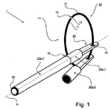
図1は、リング11を集合素子10として有し、キャップ30a-1上の連結素子60としての貫通孔の形態にある貫通開口62によって集合素子11に連結されたアプリケータ用具20a-1を、また(アプリケータ用具をともなわずに)同様の態様で集合素子11に連結されたキャップ30a-2も有する、本発明にしたがうアプリケータ用具アセンブリ1を斜視図として示す。
FIG. 1 shows an
図1の実施形態のアプリケータ用具20a-1は、アプリケータ用具20a-1の長手方向によって実質的に決定される、主軸Hを有する。アプリケータ用具20a-1は、図の左下側に非作業端40も有し、右上側にはキャップ30a-1で隠されている作業端を有する。キャップ30a-1は解除可能な結合32において取付け/取外し可能な態様でアプリケータ用具に結合される。
The
例えば筆記用具の場合、アプリケータ用具20a-1の作業端には筆先を有する筆記部材があり得る。ここでは本発明にしたがうアプリケータ用具アセンブリがアプリケータ用具の例として筆記用具を参照して説明されるが、だからといって本明細書に説明される本発明を筆記用具に限定するつもりは全く無いことに注意すべきである。
For example, in the case of a writing tool, there may be a writing member having a writing tip at the working end of the
閉じた縁を有する開口62の形態にある、本発明の第1の態様にしたがう連結素子60が、アプリケータ用具20a-1から遠い側の、キャップ30a-1の端に設けられる。集合素子10は、貫通する集合開口14を有するリング11の形の大きな構造体の形態にある。リング11は集合開口14の、本来実質上閉じている、集合縁12を有する。集合縁12は、ここでは円形である、あらかじめ定められた集合縁断面13をもつ。あるいは、集合素子10はカラビナフックの態様で構成することもでき、この点に関し、関わる原理を理解すれば、当該目的に向けられる別のいかなる形状も適することがわかるはずである。集合素子10をキャップ30a-1上の連結素子60に連結するかまたはキャップを外すため、集合開口または切れ目16が集合素子10に設けられる。
A connecting
次に、揚げ補助具70を有する、図1のアプリケータ用具20aの非作業端40の有益な代替形または発展形を説明するために、図2a及び2bを参照する。この目的のため、揚げ補助具70として作用するように、実質的にアプリケータ用具20b-1の軸線Hに対して傾けられてそれぞれ拡がる、すなわち傾斜面である2つの面72,74が、アプリケータ用具20b-1の非作業端に設けられる。あるいはまたはさらに、揚げ補助具70と本発明の第1の態様にしたがう図1に示される連結素子60はキャップ及び/または非作業端40上に統合して設けるかまたはキャップ及び/または非作業端40に一体化することもできる。したがって図1に示される連結素子60は揚げ補助具70に一体化されるであろう(例えば図3を見よ)。図2a及び2bの構成において、揚げ補助具70は非作業端40に別途作成された取付け部として設けることもでき、したがって、長さがLの、(アプリケータ用具20bの)掴み部22及び揚げ補助具70に対して異なる材料を用いることが可能である。
Reference is now made to FIGS. 2a and 2b to illustrate a beneficial alternative or development of the
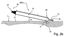
図2a及び2bはアプリケータ用具20b-1の揚げ運動における2つの状態を示す。図2aはおかれた状態にあるアプリケータ用具20b-1を示し、図2bは揚がった状態にある図2aに示されたアプリケータ用具20b-1を示す。アプリケータ用具20b-1は毛管作用ファイバ芯の形態の筆先54を有する筆記インサートからなる前部52を作業端50に有する筆記用具、例えばファインライナーである。前部は掴み部22に結合され、掴み部22を終端で閉封する。
Figures 2a and 2b show two states in the lifting movement of the
掴み部22は、筆記動作において、そこから毛管作用ファイバ芯によって筆先54に筆記液が送られる筆記液格納部材がある空洞(図示せず)を有する。そのようなファイバペンの筆先24は、特に筆先に作用する機械的要因に関して、特に繊細である。
The
図2a及び2bに示されるアプリケータ用具20b-1は、アプリケータ用具20b-1がその上におかれた支持面F上に配置され、アプリケータ用具20b-1の非作業端40に、実質的にチューブ形構成の、本発明にしたがう揚げ補助具70を有する。チューブ端の形態の揚げ補助具70は、アプリケータ用具20b-1の軸線に対して互いに180°をなして配置された、2つの実質的に傾けられた2つの面72,74を有する。この場合、2つの傾斜面の内の一方の傾斜面74が面Fに向いている。
The
男性または女性のユーザがおかれているアプリケータ用具20b-1を図2aの位置から図2bの揚げ位置に動かしたければ、ユーザは揚げ補助具70の上側の傾斜面、すなわち表面Fから離れる方向を向いている傾斜面72を少なくとも1本の指で押して、アプリケータ用具20b-1の非作業端40を表面Fの方向に動かす。この状況において、アプリケータ用具20b-1は、下側の傾斜面74がアプリケータ用具20b-1の掴み部22に移行する場所にある仮想旋回軸D(図2bを見よ)を中心にして傾く。この動作は下側の傾斜面、すなわち表面Fに向いている傾斜面74がその最も開かれた場所で、図2bに示されるアプリケータ用具20b-1の場合には揚げ補助具20のチューブ底折畳み端で、表面Fに接すると直ちに終了する。この状況において、アプリケータ用具20b-1の作業端50は完全にすなわち最大高さまで揚げられる。この状況において、アプリケータ用具20b-1の作業端50は表面Fからあらかじめ定められた高さAだけ揚げられる。揚げ高さは角度αの変化を用いて、[角度の変化]×[接触点から作業端までの距離]の正弦、すなわちA=sinα・Lとして、計算することができる。
If the
図2a及び2bのアプリケータ用具20b-1の揚げ補助具70の2つの傾斜面72,74は相互に実質的に対称である。これは、傾斜面72,74がともに同じ揚げ運動を生じさせ、したがって同じ揚げ高さAを与え得ることを意味する。したがって、図2a及び2bの揚げ補助具70の機能は、アプリケータ用具20b-1がおかれている表面F上のアプリケータ用具20b-1の正確な位置に無関係である。アプリケータ用具20b-1の横置き状況は、軸線を中心として回転されても、アプリケータ用具20b-1は最終的に下側の傾斜面74と表面Fの間に接触がなされるように自動的に方位が定められ、図2bに示されるような位置にアプリケータ用具20b-1の軸線を中心にして回転するから、揚げ補助具70の露出傾斜面72に少なくとも1本の指で圧力が加えられると完全な揚げ運動が行われる結果となる。
The two
揚げ高さAは、その高さであればユーザ側の一般的な太さの指によって作業端50の近くでアプリケータ用具20b-1のまわりを掴むことが容易に可能であることから、約18mmである。子供による、アプリケータ用具20b-1に関わる要件にしたがう使用においては特に、さらに大きい揚げ高さも可能であることは当然であろう。
The fried height A can be easily grasped around the
アプリケータ用具20b-1が、チューブ端折畳み領域において、残りの掴み部22の直径より広くなっていれば特に有益である。そのようにすれば、アプリケータ用具は揚げ補助具の作動に最適な位置に自動的に必ずあるから、ここでは特に有益である転がり停止機能を果たす。さらに、アプリケータ用具側に不要な転がり能力を与えないための別の手段を配することも可能である。
It is particularly beneficial if the
図2a及び2bに示されるアプリケータ用具20b-1の揚げが迅速かつ容易に実施され得るだけでなく、片手でも可能でさえあり得る点を簡潔に説明するために、図2a及び2bをさらに参照する。すなわち、アプリケータ用具20b-1が横置き状態にあるときに、揚げ補助具70の上側傾斜面72に、例えば右手の、小指で圧力を加えることができ、よってアプリケータ用具20b-1の非作業端40はアプリケータ用具20b-1がおかれている表面Fの方向に押される。図2bの完全に揚がった状態において、小指は揚げ補助具70上に置かれたままであるが、同じ手の親指及び人差し指はアプリケータ用具20b-1の作業端の近くでアプリケータ用具20b-1を囲むことができる。アプリケータ用具20b-1のまわりに指がおかれた後、作業端50の近くでアプリケータ用具20b-1は取り上げられ、同時に小指は揚げ補助具70の上側傾斜面71上の印加圧力を解放することができ、上側傾斜面71から離れることができる。このようにすれば、本発明にしたがうアプリケータ用具20b-1を片手で取り上げることさえも、可能である。
In order to briefly explain that the
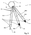
図3は、3つのアプリケータ用具20c-1〜20c-3を有する、本発明にしたがうアプリケータ用具アセンブリ1aの第2の実施形態の側面図を示す。繰り返しを避けるため、以降は図1の実施形態との違いだけを説明する。
FIG. 3 shows a side view of a second embodiment of an applicator tool assembly 1a according to the present invention having three
説明をわかりやすくするため、図3のアプリケータ用具20c-1〜20c-3は、図2a及び2bのように、ファインライナー、すなわち作業端50の前部52に筆先54をそれぞれが有する筆記用具である。筆先54は、同様に、図2a及び2bを参照して説明したような揚げ補助具20bも備えられているキャップ30b-1及び30b-2の装着によって保護される。アプリケータ用具20c-1〜20c-3の非作業端40にも図2a及び2bを参照して説明したような揚げ補助具70aが備えられている。さらに、集合素子としての、集合開口(切れ目)16をもつリング11への連結のため、非作業端40、すなわち揚げ補助具70aに、本発明にしたがう連結素子60aも設けられている。言い換えれば、揚げ補助具70の機能と連結素子60aの機能がアプリケータ用具20c-1〜20c-3の非作業端40に統合されている。
For ease of explanation, the
図4は、集合素子10への連結のために縁64に切欠き66を有する開口62の形態の、アプリケータ用具(図示せず)のためのキャップ30c上の本発明にしたがう連結素子60bの第1の実施形態の側面図を示す。リング11は、同様に、図4の断面図に示されている、集合素子10の例であるとされる。封止キャップ30cは熱可塑性材料、好ましくは生体不活性ポリプロピレン(PP)でつくることができる。
FIG. 4 shows a
連結素子60bは周縁部64に切欠き66を有する開口62の形態にあり、開口66は集合縁断面13の直径DMより小さい幅Wをもつ狭窄部を少なくとも1つ有する。集合素子10への連結素子60bの連結の形成を簡単にするため及び/または集合素子10からの連結素子60bの取外しを容易にするため、それぞれが対向して配置された、集合素子10のための平面誘導面67a',67a"及び67b',67b"が連結素子60bに設けられる。集合素子10のためのそれぞれ2つの誘導面67a',67a"及び67b',67b"は開口62の切欠き66に、連結素子60bが集合素子10に連結されるかまたは集合素子10から外されるときの狭窄部65の弾性的な開きまたは拡張を誘導面が一層容易にするような態様で、相互にある角度をなして配置される。
The connecting
開放縁部分をもつ連結素子60bの切欠き66が、開口の軸線に対して、アプリケータ用具の主軸Hと約90°の不意の外れ落ちに対する安全角をなす、径方向の作動方向を有することも利点として述べておくべきであろう。安全角は30°と150°の間の間にあるように選ばれ得ることが好ましいことも指摘しておくべきであろう。
The notch 66 of the connecting
図5aは、閉じた縁64を有する開口62の形態の、アプリケータ用具のための封止キャップ30a上の本発明にしたがう連結素子60の第2の実施形態の側面図を示す。封止キャップ30aは熱可塑性材料、好ましくは生体不活性ポリプロピレン(PP)でつくることができる。連結素子60のための開口62は射出成形作業後に、例えば中ぐりによって、付け加えることができる。必要な耐機械的負荷能力は、用いられる材料に応じて、縁64の厚さによって調節することができる。あるいは、開口62は、ラテラルプル(lateral pull)を用いて、製造中に作成しておくこともできる。
FIG. 5a shows a side view of a second embodiment of a connecting
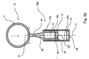
図5bは、封止キャップ30aと集合素子10の間の連結の形成を説明するための、図5aの封止キャップ30aと連結素子10としてのリング11を合わせた断面図を示す。封止キャップ30aは外側部分33a及び内側部分33bを有する。この場合、内側部分33bは、封止キャップ30aのクロージャー軸Hに沿い、軸長のほぼ1/2をこえて延び、軸Hはアプリケータ用具の主軸Hと同じである。内側部分33bの長さはキャップの軸長とほとんど同じとすることもでき、特には軸長より長くすることもできる。内側部分33bの領域において、封止キャップ30aはアプリケータ用具の作業端を受け入れるように設計される。内側部分33b及び外側部分33aは脚37によって相互に連結される。通気路39が脚37の間に設けられる。脚37は封止キャップ30aのクロージャー軸Hを中心にして実質的に星形に配置され、この結果、通気路39はクロージャー軸のまわりに実質的に対称に分散配置される。この場合に、脚37の断面は、一方では空気交換に十分な面積があり、他方では外側部分33aと内側部分33bの間の連結が機械的に十分に安定であるように、通気路39の断面より小さい。脚37の、星形構成とは別の、いずれかの配置も考えられる。
FIG. 5 b shows a cross-sectional view of the sealing
アプリケータ用具としてのペン、特にその筆先が封止キャップ30aによって閉封されるときに、筆先は封止キャップ30aの開口38内に、筆先が封止キャップ30aの内側部分33bの内部31に収まるまで、差し込まれる。例えば筆先が挿入状態にあるときに内側部分33bの内部31を密封するためのリッジ36の形態の、内側部分封止手段を設けることができる。ペン先が閉封状態で収まる領域、すなわち内側部分33bの内部領域が完全に密封されることが、図5bの断面から分かるであろう。しかし、内側部分33bは内側部分の表面35bと筆先の表面の間の、挿入状態において内側部分の表面35b及び筆先の表面と接触する、適当な嵌合せ手段により封止することもできる。脚37の間の通気路39は封止領域の外側にあり、よって封止の完全性を妨げることはない。したがって、内側部分33bの内部領域31に受け入れられている状態において筆先が乾くことはできない。内側表面35aはアプリケータ用具の作業端のためのガイドを務め、適する寸法につくることで、アプリケータ用具をキャップ30aに保持するための保持機能のための閉封力を有することができる。あるいはまたはさらに、封止キャップ30aをペンに取外し可能な態様で機械的に結合するために、ペン先の受入れを想定した開口38の近くで外側部分の内側表面35aの周縁に沿って延びるリッジ34の形態のラッチ手段を設けることもできる。
When the pen as an applicator tool, in particular, the writing tip is sealed by the sealing
図6aは、集合素子10に連結されている状態にあるキャップ30d上の、本発明にしたがう連結素子60cの第3の実施形態の側面図を示す。ここでも集合開口(切れ目)16を有するリング11が集合素子の一例として示されている。集合開口(切れ目)16におけるリング11の2つの端11a,11bは、連結素子60cの取外しまたは嵌込みに対する優先方向VRがあるように構成される。この目的のため、端11a,11bの断面は、キャップ30dを取り外すために、リングを内側から容易に曲げて開くことができるようにあるいは集合開口(切れ目)16を拡張することができるように、丸められるかまたはリング11の内側に対して傾けられる。リングからキャップ30dを内側から取り外すことができるように、リングの直径D1はキャップ30dの適切な長さD2より若干大きい。よって、アプリケータ用具をともなっていない、キャップ30dは、キャップ30dを内側から外側に向けて取り外すために、リング11の集合縁12を中心にしてまわしてリングの内側で内向きにすることができる。これは、特にアプリケータ用具がキャップに連結されているときに、キャップの不意の外れ落ちを妨げるから有益である。
FIG. 6 a shows a side view of a third embodiment of a connecting
図6bはキャップ30dと集合素子10の間の、不意の外れ落ちに対して防護される、連結の形成を説明するための図3aのキャップ30dの側面図を示す。図6bのキャップ30dの連結素子60cは、基本的にキャップ30dを前述したようにしかリング11から取り外すことができないように、適合される。連結開口の形態の、周縁部64が閉じられている開口62が形成される。集合素子10への連結素子60cの結合の形成を簡易化するため、及び/または集合素子10からの連結素子60cの取外しを容易にするために、連結切れ目または開口62の縁部64上に材料弱化部66bが設けられる。材料弱化部66bは開口62の軸線に対して縁部64にかけて実質的に径方向に拡がる。材料弱化部66bの幅はリング11の集合縁断面の直径のほぼ相当する。
FIG. 6b shows a side view of the
図6aを参照して説明したように、集合素子10の集合開口(切れ目)16とアプリケータ用具の作業端のためのキャップ30d上の連結素子60cは、アプリケータ用具がともなわれていない場合に限り、集合素子10の内側から径方向に外側に向けてキャップ30dを取り外すことができるように適合される。この目的のため、連結素子60Aは、開口62の軸線に対して径方向の、アプリケータ用具の主軸Hと実質的に一致する第1の作動方向R1を有する。第1の作動方向R1には、第1の作動方向R1に対して実質的に垂直方向に延びる第2の作動方向が接する。
As described with reference to FIG. 6a, the collective opening (cut) 16 of the
言い換えれば、キャップ30dを取り外すには、キャップ30dを内側に回し、次いで矢印R1(図6b)の方向に対向する矢印VR(図6a)の方向に外側に押さなければならない。この場合、材料弱化部66bが集合開口(切れ目)16を通る。次いで、矢印R2の方向に対向する方向にキャップ30dを集合縁から取り外すことができる。言い換えれば、集合素子10の集合縁12は取外し手順において矢印R1及びR2(図6b)にしたがう。キャップ30dを連結する操作はキャップだけで実行され得るが、特に、キャップとアプリケータ用具が結合されていても実行され得る。
In other words, to remove the
キャップ30dを集合縁に再度連結するため、連結素子60cのオリフィスが集合縁上で矢印R2の方向に対向する方向に押される。その前または後に、キャップ30dが、材料弱化部66bが集合縁12のベベル端面11a,11bを押し開くことができるように集合縁12の径方向に外側に向けられる。次いで、集合開口(切れ目)16及び集合縁12が材料弱化部66bと位置合せされるように向けられて集合縁12が矢印R1の方向に対向する方向に内側に引かれ、この場合には材料弱化部66bが集合縁12の集合開口(切れ目)16を通る。
In order to reconnect the
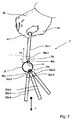
図7は、4つのアプリケータ用具20a-1〜20a-4を含む、本発明にしたがうアプリケータ用具アセンブリ1*の側面図を示し、移動の目的のため、アセンブリは、手80の人差し指80と親指84の間にアプリケータ用具20a-1がつままれて、手80で保持されている。
FIG. 7 shows a side view of an
図7の目的は、本発明にしたがうアプリケータ用具アセンブリによって達成される利点を説明することである。複数のアプリケータ用具を−所望であれば−あらかじめ定められた順序の、アセンブリの形態で収容し、移動させることができる。これは、個々のアプリケータ用具20a-1〜20a-4の、例えば色及び/または与えられた色調の濃淡及び/または異なる塗布幅による、それらの順序に関するあらかじめ定められた特徴が異なる場合に、特に有益である。所望の順序の配列をいつまでも保証するため、それぞれのアプリケータ用具のキャップがアプリケータ用具の作業端と付帯するキャップに関して幾何学的断面形状を必要とし、そのような断面が例えばキー−ロック原理にしたがって相互に整合されていれば、特に有益である。より簡易な別形として、カラーキャップコードを用いることもできる。このようにすれば、それぞれのアプリケータ用具を与えられたキャップと視覚的及び/機械的に関連付けることができ、よって、アプリケータ用具が整然と配列された正しい順序が守られる。
The purpose of FIG. 7 is to illustrate the advantages achieved by an applicator tool assembly according to the present invention. Multiple applicator devices can be housed and moved in the form of an assembly, if desired, in a predetermined order. This is the case when the predetermined characteristics of the
図7において、それぞれの連結素子60dはそれぞれのアプリケータ用具20a-1〜20a-4の作業端のためのそれぞれのキャップ30d-1〜30d-4上に配置される。キャップ30d-1〜30d-4のそれぞれとそれぞれのアプリケータ用具20a-1〜20a-4の間のそれぞれの解除可能な連結は、キャップ30d-1〜30d-4からアプリケータ用具20a-1〜20a-4を取り外すには、1つのアプリケータ用具の重量によってかかる力を減じた、アプリケータ用具アセンブリ1*の全体の重量による重力Gより大きい、閉封力VKを上回る力が必要であるような構造をもつ。力の関係が相互に整合する別の態様も可能であることは当然であろう。連結素子60d上に、例えば図3に示されるキャップのような、キャップ30d-1〜30d-4は本発明にしたがう受入れ補助具70cを有する。すなわち、本発明にしたがうそれぞれの連結素子は、それぞれのキャップ上で、本発明にしたがう受入れ補助具70cと一体化される。
In FIG. 7, each connecting
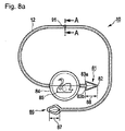
図8aはアプリケータ用具のための集合素子10に対する好ましい実施形態を示す。集合素子はその端において、対応する、集合縁12を可逆的に開閉するためのクロージャーのクロージャー素子81,86を有する。図において、羽付鏃形素子81が中空素子とループの態様で嵌め合わされ得る、外側輪郭及び内側輪郭が平四辺形または洋凧形(菱形)の形態の形状につくられている、プラグ素子86に対応する。
FIG. 8a shows a preferred embodiment for an
クロージャーを閉じるためには、鏃形素子81が洋凧形素子86を通して嵌め合わされなければならず、この際、鏃形素子81の洋凧形素子86からの抜け落ちを防止するために確実に留められるように、逆刺83a,83bの内の少なくとも一方が洋凧形素子86を突き抜けるかまたは中空素子がプラグ素子を突き抜ける。クロージャーを開くためには、鏃形素子81が洋凧形素子86の開口によって定められる領域に対して垂直方向に向けられ、2つの逆刺83a,83bが洋凧形素子の最も広い内寸87に対応するように向けられる。精確にこの位置において、クロージャーの解錠、すなわち鏃形素子81の洋凧形素子86を通る逆方向の運動が可能である。
In order to close the closure, the saddle-shaped
逆に、引張り力負荷の下でのクロージャーの不意の解錠を実質的に防止するため、鏃形素子81の長さ88は洋凧形素子86の内寸87より大きい。このようにすれば、鏃形素子81は鏃形素子81の逆刺83a,83bの一方が洋凧形素子86に掛かり嵌合している点を中心にして、鏃形素子81の前端82が洋凧形素子86の対向端に当たってしまってから先には、洋凧形素子86内で回転することはできない。この結果、鏃形素子81は「横向き」関係においては洋凧形素子86から離れることはできないが、鏃形素子81と洋凧形素子86の開口領域の間で上述した垂直方位にあるときに限り離れることができる。
Conversely, the
洋凧形素子86は、アプリケータ用具が嵌め入れられるかまたは取り外されるときに菱形が変形される、すなわちアプリケータ用具の連結素子によって押し縮められるように、弾性をもつ形状であるように適合される。これにより、アプリケータ用具を集合素子から取り外すにはあらかじめ定められた力を上回る力が必要になることが保証される。
The crab-shaped
集合素子10の形成長に依存して、鏃形素子81と洋凧形素子86は、本発明にしたがう複数のアプリケータ用具アセンブリを連結するかまたは1つにまとめるために用いることもでき、あるいは素子を集合させるために用いることもできる。一方で、ユーザが自由に、1つの集合素子10の集合開口を別の集合縁に通過させ、よって2つの集合素子自体を相互に嵌め合わせて、鎖と同様に、配置できることは当然であろう。しかし、クロージャー素子を用いて集合素子を1つに連結することも可能である。すなわち、第1の集合素子の鏃形素子を第2の集合素子の洋凧形素子に、またはその逆に、連結することも可能である。
Depending on the formation length of the
鏃形素子81に対して短い距離で集合素子上にコインの形態の掴み素子84が備えられる。掴み素子84には、構造の形態にある、及び/または材料の多数の色の組合せとして、及び/またはインクまたは色素の塗布によって、視認可能にされた製造元識別標識85が付けられる。鏃形素子81の近くに掴み素子84を配置することで比較的頑丈な連結が得られ、したがって、集合素子の開閉時に、簡便で、心地よく、慎重なハンドリングが可能になる。
A gripping
2つの同様な集合縁のクロージャー素子が連結し合わされている状況において、第1及び第2の集合素子の集合縁を、掴み素子84はさらに、2つの別々の集合縁領域を利用して本来閉じられている(2部構成の)集合縁上にペンを、ある周縁上で、配置できるように相互に離しておく機能を果たす。
In the situation where two similar collecting edge closure elements are joined together, the grasping
さらに、集合素子10はあらかじめ定められた弱化領域または所望の分裂領域91を有する。領域91は、図8bにさらに示される、メクラ穴またはリセス89の形態の、あらかじめ定められた材料弱化領域を含む。そのようなリセス89は、例えば用いられる射出成形金型の適切な構造によって設けることができ、あるいは(用いられるそれぞれの材料に依存して)後から集合素子の切削加工または熱処理によって作成することができる。この点に関し、残りの断面領域90は、15Nと40Nの間の範囲にあることが好ましく、23Nと27Nの間の範囲にあることが特に好ましい、断面領域90に作用するあらかじめ定められた張力で裂け、よって集合素子が開くような寸法につくられる。
Furthermore, the
本発明の別の態様にしたがえば、複数のアプリケータ用具を一緒にしたアプリケータ用具アセンブリのための本発明にしたがう集合素子は、パーツキット、特にセールスユニットを形成することができる。本発明のアプリケータ用具アセンブリはそのようなパーツキットまたはセールスユニットのパーツで形成することができる。 In accordance with another aspect of the present invention, an assembly element according to the present invention for an applicator tool assembly that combines a plurality of applicator tools can form a part kit, particularly a sales unit. The applicator tool assembly of the present invention can be formed from such parts kit or parts of a sales unit.
終わりにあたって、本明細書の説明が実質的に少なくとも2つのアプリケータ用具を一緒にしたアプリケータ用具アセンブリだけに集中されているとしても、上述したアプリケータ用具の特徴を有し、よって本発明にしたがうアプリケータ用具アセンブリ上での使用に適するアプリケータ用具が本発明の主題であると見なされるべきであることは当然であろうということにも注意すべきである。 At the end, even though the description herein is substantially focused only on an applicator tool assembly that combines at least two applicator tools, it has the features of the applicator tool described above, and thus is consistent with the present invention. It should also be noted that an applicator tool suitable for use on an applicator tool assembly thus should be considered the subject of the present invention.
1,1a,1* アプリケータ用具アセンブリ
10 集合素子
11 リング
12 集合縁
13 集合縁断面
14 集合開口
16 切れ目
20a,20b,20c アプリケータ用具
30a,30b,30d 封止キャップ
33a 封止キャップ外側部分
33b 封止キャップ位置側部分
38 封止キャップ開口
39 通気路
40 非作業端
50 作業端
54 筆先
60,60a,60b,60c 連結素子
62 貫通開口
64 連結素子周縁部
66 切欠き
70,70a,70b,70c 揚げ補助具
72,74 揚げ補助具傾斜面
81,86 クロージャー素子
84 親指
87 クロージャー素子最大内寸
91 分裂領域
H 主軸
1, 1a, 1 *
Claims (15)
集合素子(10)、及び
少なくとも2つのアプリケータ用具(20a-1;20b-1;20c-1,20c-2,20c-3;20a-1,20a-2,20a-3,20a-4)、
を含み、
前記アプリケータ用具のそれぞれが、実質的に前記アプリケータ用具の長手方向によって決定される主軸(H)、及び、少なくとも1つの作業端(50)及び少なくとも1つの非作業端(40)を有し、前記作業端及び前記非作業端の内の一方の領域に少なくとも1つの連結素子(60;60a;60b;60c;60d)を有し、
さらに、前記集合素子が前記アプリケータ用具のそれぞれにそれぞれの前記連結素子を用いて連結され、
前記集合素子(10)が、所望の分裂領域(91)としてあらかじめ定められた弱化部を備えることにより、15Nと40Nの間の範囲にある、あらかじめ定められた張力負荷において裂けるような形状寸法につくられる、
ことを特徴とするアプリケータ用具アセンブリ(1,1a,1*)。 In the applicator tool assembly,
An assembly element (10) and at least two applicator tools (20a-1; 20b-1; 20c-1, 20c-2, 20c-3; 20a-1, 20a-2, 20a-3, 20a-4) ,
Including
Each of the applicator tools has a main axis (H) substantially determined by the longitudinal direction of the applicator tool, and at least one working end (50) and at least one non-working end (40). At least one connecting element (60; 60a; 60b; 60c; 60d) in one region of the working end and the non-working end;
Further, the assembly elements are connected to each of the applicator tools using the respective connection elements,
The collective element (10) is provided with a weakened portion predetermined as a desired splitting region (91), so that it has a shape and dimension that can be broken at a predetermined tensile load in a range between 15N and 40N. able to make,
Applicator tool assembly (1, 1a, 1 * ) characterized in that.
前記第1のクロージャー素子(86)の最大内寸(87)が前記第2のクロージャー素子(81)の、前記集合縁(12)または前記プラグの差込み方向に対して垂直な、最大外寸より若干小さい、
ことを特徴とする請求項5に記載のアプリケータ用具アセンブリ。 As closure element (81, 86) of the corresponding first closure element (86) of the hollow shape, and can be locked to the first closure element (86), the second closure element in the form of a plug element ( 81) is provided,
The maximum inner dimension (87) of the first closure element (86) is greater than the maximum outer dimension of the second closure element (81) perpendicular to the collecting edge (12) or the plug insertion direction. Slightly smaller,
6. An applicator tool assembly according to claim 5 wherein:
2つの前記集合素子(10)がさらに大きな集合素子を与えるために、別の集合素子のクロージャー素子(81,86)にも対応するような形態を有している前記クロージャー素子(81,86)によって、連鎖を形成できることを特徴とする請求項5から7のいずれかに記載のアプリケータ用具アセンブリ。 A plurality of said collective elements (10) can form a chain to give a larger collective element;
The closure element (81, 86) has a configuration corresponding to the closure element (81, 86) of another aggregation element in order that the two aggregation elements (10) give a larger aggregation element. The applicator tool assembly according to any one of claims 5 to 7 , wherein a chain can be formed.
前記クロージャー軸(H)が、少なくとも部分的に、前記通気路の断面に対して実質的に垂直であり、
前記封止キャップが外側部分(33a)及び内側部分(33b)を有し、前記少なくとも1つの通気路(39)が前記外側部分(33a)と前記内側部分(33b)の間に形成されており、及び
前記連結素子(60;60a;60c)が、閉じた周縁部分(64)を有する開口(62)を備えているとともに、前記キャップの前記開口とは反対側に取り付けられている、
ことを特徴とする請求項1から9のいずれかに記載のアプリケータ用具アセンブリ(1,1a,1*)。 Before SL applicator tool (20a-1; 20b-1 ; 20c-1,20c-2,20c-3; 20a-1,20a-2,20a-3,20a-4) each are of the respective application at least one opening for閉封receives the working end of the capacitor equipment (38), substantially perpendicular closure axis with respect to the cross-sectional area of the opening (38) (H), and at least one vent with the road (39), each of the caps have a (30a-1,30a-2; 30d -1,30d-2,30d-3,30d-4; 30a),
Said closure axis (H) is, at least in part, Ri substantially perpendicular der respect cross section of the air passage,
The sealing cap has an outer portion (33a) and an inner portion (33b), is formed between the at least one air passage (39) said outer portion (33a) and the inner portion (33b) , and the connecting element (60; 60a; 60c), together with has an opening (62) having a closed peripheral portion (64), and the opening of the cap is attached to the opposite side,
10. An applicator tool assembly (1, 1a, 1 * ) according to any one of the preceding claims .
前記揚げ補助具(70;70a,70b;70c)が、前記非作業端(40)及び/または前記キャップ(30b-2;30d-1,30d-2,30d-3,30d-4)にある、前記アプリケータ用具の前記主軸(H)に対して少なくとも1つの実質的に傾斜した面(72,74)の形態にあり、及び
前記揚げ補助具(70;70a,70b;70c)が、前記揚げ補助具の操作時に前記アプリケータ用具の前記他端を前記アプリケータ用具がおかれた表面(F)に対して少なくともあらかじめ定められた揚げ高さ(A)まで梃子のように揚げることができるような形態を有し、前記揚げ高さが人の指球の平均高さによって定められる指球高以上である、
ことを特徴とする請求項1から13のいずれかに記載のアプリケータ用具アセンブリ(1a,1*)。 Before SL applicator tool (20a-1; 20b-1 ; 20c-1,20c-2,20c-3; 20a-1,20a-2,20a-3,20a-4) wherein the non-working end (40) And / or the cap (30b-1, 30b-2; 30d-1, 30d-2, 30d-3, 30d-4) can be operated with one hand to lift each other end of the applicator tool. At least one of fried aid (70; 70a, 70b; 70c ) is provided,
The frying aid (70; 70a, 70b; 70c) is on the non-working end (40) and / or the cap (30b-2; 30d-1, 30d-2, 30d-3, 30d-4) In the form of at least one substantially inclined surface (72, 74) relative to the main axis (H) of the applicator tool, and the frying aid (70; 70a, 70b; 70c) During operation of the frying aid, the other end of the applicator tool can be fried like an insulator to at least a predetermined frying height (A) with respect to the surface (F) on which the applicator tool is placed. Having a form such that the fried height is equal to or higher than a fingerball height determined by an average height of a human fingerball
Applicator tool assembly (1a, 1 * ) according to any of the preceding claims .
前記転がり止めが、前記アプリケータ用具の前記非作業端(40)にある前記揚げ補助具と、前記非作業端(40)によって、統合され、前記転がり止めが、前記非作業端(40)を閉じる端の、前記アプリケータ用具の直径をこえて突き出す、少なくとも1つの縁端によって形成されていることを特徴とする請求項14に記載のアプリケータ用具アセンブリ(1a,1*)。 The applicator tool around the main axis (H) of the applicator tool (20a-1, 20c-1, 20c-2, 20c-3; 20a-1, 20a-2, 20a-3, 20a-4) rolling prevents the respective rolling stop is provided for the applicator tool,
The rolling stops are said fried aid in the in the non-working end (40) of the applicator tool, wherein the non-working end (40), are integrated, the rolling stop is, the non-working end (40) Close end, protruding beyond the diameter of the applicator tool, the at least one formed by the edge 14. applicator tool assembly wherein Tei Rukoto (1a, 1 *).
Applications Claiming Priority (3)
| Application Number | Priority Date | Filing Date | Title |
|---|---|---|---|
| DE202009007040U DE202009007040U1 (en) | 2009-05-15 | 2009-05-15 | Appliance bundle and applicator suitable for this |
| DE202009007040.9 | 2009-05-15 | ||
| PCT/EP2010/002955 WO2010130451A1 (en) | 2009-05-15 | 2010-05-12 | Applicator instrument assembly and applicator instrument suitable for same |
Publications (2)
| Publication Number | Publication Date |
|---|---|
| JP2012526674A JP2012526674A (en) | 2012-11-01 |
| JP5756089B2 true JP5756089B2 (en) | 2015-07-29 |
Family
ID=42315875
Family Applications (1)
| Application Number | Title | Priority Date | Filing Date |
|---|---|---|---|
| JP2012510170A Active JP5756089B2 (en) | 2009-05-15 | 2010-05-12 | Applicator tool assembly and applicator tool suitable therefor |
Country Status (5)
| Country | Link |
|---|---|
| EP (1) | EP2429831B1 (en) |
| JP (1) | JP5756089B2 (en) |
| CN (1) | CN102421606B (en) |
| DE (2) | DE202009007040U1 (en) |
| WO (1) | WO2010130451A1 (en) |
Cited By (1)
| Publication number | Priority date | Publication date | Assignee | Title |
|---|---|---|---|---|
| JP2024017510A (en) * | 2022-07-28 | 2024-02-08 | ミクロ株式会社 | Thin writing instruments and their sets |
Families Citing this family (1)
| Publication number | Priority date | Publication date | Assignee | Title |
|---|---|---|---|---|
| FR2995878B1 (en) | 2012-09-24 | 2014-09-05 | Maped | PACKAGING FOR WRITING INSTRUMENTS |
Family Cites Families (15)
| Publication number | Priority date | Publication date | Assignee | Title |
|---|---|---|---|---|
| US1537192A (en) | 1923-12-05 | 1925-05-12 | Charles M Rice | Pencil-holding device for key rings |
| DE1938045U (en) | 1966-02-04 | 1966-05-05 | C Kreul Fa | TUBE PEN FOR RELIEF-LIKE PAINT APPLICATION. |
| JPS4732024U (en) * | 1971-04-28 | 1972-12-11 | ||
| JPS5281224U (en) * | 1975-12-15 | 1977-06-17 | ||
| DE7911160U1 (en) | 1979-04-17 | 1979-09-27 | Linhardt & Co, Metallwarenfabrik, 8374 Viechtach | TUBE-SHAPED ADVERTISING DEVICE. |
| JPS57189483U (en) * | 1981-05-26 | 1982-12-01 | ||
| IT207915Z2 (en) * | 1986-01-10 | 1988-02-22 | Dajna Di Aldo Moro | KEYRING WITH BALLPOINT PEN OR PENCIL OR SIMILAR |
| JPH0261481U (en) * | 1988-10-31 | 1990-05-08 | ||
| US6000103A (en) * | 1998-05-08 | 1999-12-14 | Paice; Bette | Portable pencil pocket |
| JP2004291379A (en) * | 2003-03-27 | 2004-10-21 | Sailor Pen Co Ltd:The | Writing implement with string |
| US6979143B2 (en) * | 2003-06-11 | 2005-12-27 | Forever Green Holdings, Llc | Carabiner writing instrument |
| KR100676741B1 (en) * | 2005-01-17 | 2007-01-31 | 주식회사 모리스 | Pull-out telescopic writing instruments |
| US7563047B2 (en) | 2005-04-25 | 2009-07-21 | Paluda Andrew J | Traveling crayon holder |
| WO2008001576A1 (en) * | 2006-06-29 | 2008-01-03 | Grazie Co., Ltd. | Hanger and small article hanging set using it |
| GB2450370A (en) * | 2007-06-22 | 2008-12-24 | Mark Andrew Nicholls | Pencil/pen with retractable reel |
-
2009
- 2009-05-15 DE DE202009007040U patent/DE202009007040U1/en not_active Expired - Lifetime
-
2010
- 2010-05-12 JP JP2012510170A patent/JP5756089B2/en active Active
- 2010-05-12 CN CN201080019078.8A patent/CN102421606B/en active Active
- 2010-05-12 WO PCT/EP2010/002955 patent/WO2010130451A1/en not_active Ceased
- 2010-05-12 EP EP10723507.9A patent/EP2429831B1/en active Active
- 2010-05-12 DE DE202010018587.4U patent/DE202010018587U1/en not_active Expired - Lifetime
Cited By (2)
| Publication number | Priority date | Publication date | Assignee | Title |
|---|---|---|---|---|
| JP2024017510A (en) * | 2022-07-28 | 2024-02-08 | ミクロ株式会社 | Thin writing instruments and their sets |
| JP7734422B2 (en) | 2022-07-28 | 2025-09-05 | ミクロ株式会社 | Thin writing implements and sets |
Also Published As
| Publication number | Publication date |
|---|---|
| WO2010130451A1 (en) | 2010-11-18 |
| DE202010018587U1 (en) | 2017-12-20 |
| JP2012526674A (en) | 2012-11-01 |
| CN102421606A (en) | 2012-04-18 |
| CN102421606B (en) | 2015-09-09 |
| EP2429831A1 (en) | 2012-03-21 |
| DE202010018587U9 (en) | 2018-03-15 |
| DE202009007040U1 (en) | 2010-10-14 |
| EP2429831B1 (en) | 2018-06-06 |
Similar Documents
| Publication | Publication Date | Title |
|---|---|---|
| WO2007024663A2 (en) | Writing instrument with multi-mode tethering | |
| US9333796B2 (en) | Fingertip mountable writing instrument | |
| US5411344A (en) | Safety marking pen for small children | |
| JP2012526674A (en) | Applicator tool assembly and applicator tool suitable therefor | |
| WO2016018976A1 (en) | A multi-purpose combination writing instrument | |
| US10406849B1 (en) | Training pen for writing | |
| US9764590B2 (en) | Stabilized writing instrument | |
| CN214928472U (en) | Novel hole pen | |
| CN209738606U (en) | Pencil sheath | |
| CN222172442U (en) | Hard contact lens suction rod protection device | |
| CN210881417U (en) | Modeling pen | |
| CN209794954U (en) | Anti-falling transparent splicing pen | |
| DE202010006765U1 (en) | Appliance bundle and applicator suitable for this | |
| CN209257714U (en) | A kind of portable stretchable ball pen | |
| CN209320536U (en) | A kind of hand hay cutter label random notes loose-leaf notebook | |
| JP4633966B2 (en) | Writing instrument | |
| CN206106724U (en) | Mark's pen shell and mark's pen | |
| US20100209171A1 (en) | Two in one pen with pencil graphite and refill ball pen | |
| DE102009021536B4 (en) | Applicators Bund | |
| CN2425779Y (en) | Safety ballpoint pen for children | |
| CN2291306Y (en) | Writing-core replaceable pencil with gripper | |
| CN200962780Y (en) | Portable folding fishing device | |
| CN104786701B (en) | A kind of pen of band erasing rubber | |
| TH38661A3 (en) | Finger-grip stationery | |
| CN205515822U (en) | Disposable syringe prevent needle cap of pricking hand |
Legal Events
| Date | Code | Title | Description |
|---|---|---|---|
| A977 | Report on retrieval |
Free format text: JAPANESE INTERMEDIATE CODE: A971007 Effective date: 20130523 |
|
| A131 | Notification of reasons for refusal |
Free format text: JAPANESE INTERMEDIATE CODE: A131 Effective date: 20130604 |
|
| A601 | Written request for extension of time |
Free format text: JAPANESE INTERMEDIATE CODE: A601 Effective date: 20130904 |
|
| A602 | Written permission of extension of time |
Free format text: JAPANESE INTERMEDIATE CODE: A602 Effective date: 20130911 |
|
| A601 | Written request for extension of time |
Free format text: JAPANESE INTERMEDIATE CODE: A601 Effective date: 20131004 |
|
| A602 | Written permission of extension of time |
Free format text: JAPANESE INTERMEDIATE CODE: A602 Effective date: 20131011 |
|
| A521 | Request for written amendment filed |
Free format text: JAPANESE INTERMEDIATE CODE: A523 Effective date: 20131101 |
|
| A131 | Notification of reasons for refusal |
Free format text: JAPANESE INTERMEDIATE CODE: A131 Effective date: 20140422 |
|
| A521 | Request for written amendment filed |
Free format text: JAPANESE INTERMEDIATE CODE: A523 Effective date: 20140722 |
|
| TRDD | Decision of grant or rejection written | ||
| A01 | Written decision to grant a patent or to grant a registration (utility model) |
Free format text: JAPANESE INTERMEDIATE CODE: A01 Effective date: 20150507 |
|
| A61 | First payment of annual fees (during grant procedure) |
Free format text: JAPANESE INTERMEDIATE CODE: A61 Effective date: 20150528 |
|
| R150 | Certificate of patent or registration of utility model |
Ref document number: 5756089 Country of ref document: JP Free format text: JAPANESE INTERMEDIATE CODE: R150 |
|
| R250 | Receipt of annual fees |
Free format text: JAPANESE INTERMEDIATE CODE: R250 |
|
| R250 | Receipt of annual fees |
Free format text: JAPANESE INTERMEDIATE CODE: R250 |
|
| R250 | Receipt of annual fees |
Free format text: JAPANESE INTERMEDIATE CODE: R250 |
|
| R250 | Receipt of annual fees |
Free format text: JAPANESE INTERMEDIATE CODE: R250 |
|
| R250 | Receipt of annual fees |
Free format text: JAPANESE INTERMEDIATE CODE: R250 |
|
| R250 | Receipt of annual fees |
Free format text: JAPANESE INTERMEDIATE CODE: R250 |
|
| R250 | Receipt of annual fees |
Free format text: JAPANESE INTERMEDIATE CODE: R250 |
|
| R250 | Receipt of annual fees |
Free format text: JAPANESE INTERMEDIATE CODE: R250 |