JP5753372B2 - Data processing apparatus and control method thereof - Google Patents
Data processing apparatus and control method thereof Download PDFInfo
- Publication number
- JP5753372B2 JP5753372B2 JP2010264296A JP2010264296A JP5753372B2 JP 5753372 B2 JP5753372 B2 JP 5753372B2 JP 2010264296 A JP2010264296 A JP 2010264296A JP 2010264296 A JP2010264296 A JP 2010264296A JP 5753372 B2 JP5753372 B2 JP 5753372B2
- Authority
- JP
- Japan
- Prior art keywords
- input
- data
- output
- control signal
- router
- Prior art date
- Legal status (The legal status is an assumption and is not a legal conclusion. Google has not performed a legal analysis and makes no representation as to the accuracy of the status listed.)
- Active
Links
Images


Classifications
-
- H—ELECTRICITY
- H04—ELECTRIC COMMUNICATION TECHNIQUE
- H04L—TRANSMISSION OF DIGITAL INFORMATION, e.g. TELEGRAPHIC COMMUNICATION
- H04L45/00—Routing or path finding of packets in data switching networks
- H04L45/02—Topology update or discovery
-
- H—ELECTRICITY
- H04—ELECTRIC COMMUNICATION TECHNIQUE
- H04L—TRANSMISSION OF DIGITAL INFORMATION, e.g. TELEGRAPHIC COMMUNICATION
- H04L45/00—Routing or path finding of packets in data switching networks
- H04L45/54—Organization of routing tables
Description
本発明はデータ処理装置及びその制御方法に関し、特に、ネットワークオンチップシステムを用いたデータ処理装置においてデータ通信効率を向上させるための技術に関する。 The present invention relates to a data processing apparatus and a control method thereof, and more particularly to a technique for improving data communication efficiency in a data processing apparatus using a network-on-chip system.
SoC(System−on−Chip)におけるIP(Intellectual Property)コア間のデータ通信技術として、ネットワークオンチップが知られている(非特許文献1を参照)。これは、コンピュータネットワークの発想をチップ内のモジュール間通信に応用した技術である。 As a data communication technique between IP (Intellectual Property) cores in SoC (System-on-Chip), a network-on-chip is known (see Non-Patent Document 1). This is a technology that applies the idea of a computer network to inter-module communication within a chip.
ネットワークオンチップを用いたシステムは、一般的に複数のデータ処理モジュール(IPコア)と複数のルータとを備え、各データ処理モジュールはルータを介してデータを授受する。データの通信経路はファームウェアなどから設定することができる。これにより、データを処理するデータ処理モジュールの順序などを動的に変更できるため、柔軟性の高いデータ処理装置を実現可能となる。また、ルータを介して通信をするので、データ処理モジュールと他のデータ処理モジュールとを網羅的に信号線で直結する必要がない。このため、配線の削減が可能である。更に、データ処理モジュールの追加が容易であるので、拡張性にも優れている。 A system using a network-on-chip generally includes a plurality of data processing modules (IP cores) and a plurality of routers, and each data processing module transmits and receives data via the routers. The data communication path can be set from firmware or the like. As a result, the order of data processing modules for processing data can be dynamically changed, so that a highly flexible data processing apparatus can be realized. In addition, since communication is performed via a router, it is not necessary to connect the data processing module and other data processing modules directly with a signal line. For this reason, wiring can be reduced. Furthermore, since it is easy to add a data processing module, the extensibility is excellent.
上記のルータは複数の入力ポートと複数の出力ポートとを具備し、各入力ポートへ入力されたデータに対して適切な出力ポートを選択して出力する。従来、ルータはデータ出力先の選択に、受け取った通信データに付随する情報を参照するのが一般的であった。例えば非特許文献1の10章や非特許文献2に記載されている構成では、送信先を識別するためのアドレス情報を通信データに付加し、このアドレス情報を基にルーティングを行う。
The router includes a plurality of input ports and a plurality of output ports, and selects and outputs an appropriate output port for data input to each input port. Conventionally, a router generally refers to information associated with received communication data when selecting a data output destination. For example, in the configuration described in Chapter 10 of
しかしながら、上記の従来の構成では通信データに付加した情報の分だけ通信しなければならない情報の情報量が増える。そのため、データ通信のオーバーヘッドとなる。そこで、本発明はこのオーバーヘッドが低減されたデータ通信技術を提供することを目的とする。 However, in the conventional configuration described above, the amount of information that must be communicated increases by the amount of information added to the communication data. Therefore, it becomes an overhead of data communication. Accordingly, an object of the present invention is to provide a data communication technique with reduced overhead.
上記目的を達成するため、本発明によるデータ処理装置は以下の構成を備える。即ち、
入力データに基づいてデータ処理を実施する複数のモジュールと、
前記入力データを転送するためのタイミングで制御信号を出力する制御手段と、
複数の入力ポートと、複数の出力ポートと、複数のデマルチプレクサと、記憶手段であって、前記入力ポートの識別情報、前記入力ポートへの入力タイミングの前記制御信号の値、前記出力ポートの識別情報及び前記出力ポートへの出力タイミングの前記制御信号の値、の対応関係を示す対応情報を記憶する記憶手段とを備え、前記複数のモジュール間でのデータ転送をする複数のルータと、
を備え、
前記デマルチプレクサは、前記入力ポートへの入力タイミングの前記制御信号に対応して、前記複数の入力ポートの1つを前記対応情報に基づいて前記複数の出力ポートの1つに関連付け、
前記制御信号は前記データとは異なる別のものであり、
前記制御手段は各ルータに共通信号としてクロックサイクルごとに値を切り替えて前記制御信号を出力し、前記ルータは、前記制御手段が出力した制御信号の値が前記対応情報に示された前記出力ポートへの出力タイミングの前記制御信号の値のときに前記関連付けた出力ポートに前記入力データを出力する
ことを特徴とする。
In order to achieve the above object, a data processing apparatus according to the present invention comprises the following arrangement. That is,
A plurality of modules for performing data processing based on input data;
Control means for outputting a control signal at a timing for transferring the input data;
A plurality of input ports, a plurality of output ports, a plurality of demultiplexers , and storage means, the identification information of the input port, the value of the control signal of the input timing to the input port, the identification of the output port Storage means for storing correspondence information indicating a correspondence relationship between the information and the value of the control signal of the output timing to the output port, and a plurality of routers for transferring data between the plurality of modules;
With
The demultiplexer, in response to said control signal input timing to the input port, associating one of the plurality of input ports to one of said plurality of output ports based on the correspondence information,
The control signal is different from the data;
The control means switches the value for each clock cycle as a common signal to each router and outputs the control signal, and the router outputs the control signal value output by the control means in the output port indicated in the correspondence information the fact outputs the input data to the output port associated with the time value of the control signal output timing to be characterized.
本発明によれば、オーバーヘッドが低減されたデータ通信技術を提供することができる。 According to the present invention, it is possible to provide a data communication technique with reduced overhead.
以下、添付図面を参照して本発明の実施の形態を詳細に説明する。 Hereinafter, embodiments of the present invention will be described in detail with reference to the accompanying drawings.
以下、添付図面を参照して本発明に係る実施の形態を詳細に説明する。ただし、この実施の形態に記載されている構成要素はあくまでも例示であり、本発明の範囲をそれらのみに限定する趣旨のものではない。 Embodiments according to the present invention will be described below in detail with reference to the accompanying drawings. However, the constituent elements described in this embodiment are merely examples, and are not intended to limit the scope of the present invention only to them.
(処理概要)
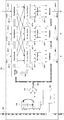
図1に本発明の実施形態におけるデータ処理装置の構成例を示す。図1中、100は本データ処理装置である。本実施形態では、データ処理装置100の入力は画像データとする。入力された画像データに対し、各IP(Intellectual Property)コア210で動作モードに応じた画像処理を施して処理結果の画像を出力する。
(Outline of processing)
FIG. 1 shows a configuration example of a data processing apparatus according to an embodiment of the present invention. In FIG. 1,
IPコア210は、例えば色空間変換モジュール、フィルタ演算モジュール、解像度変換モジュールなどである。これらのモジュールが画像を処理する順序は一意ではない。ルータ230が画像データを動的にルーティングすることで、動作モードに応じて処理順序を変更できるようにする。また、処理順序の異なる複数の画像データシーケンスを同時に処理できるようにする。
The
このような処理を実現するため、本実施形態に係るルータ230はデータを受け取ったタイミングを基にルーティングを行う。このタイミングは、スロット制御部240が生成する通信制御信号245により制御される。このため、例えば送信先アドレスなどの情報を画像データに付随させる必要がない。したがって、各要素間を繋ぐ信号線のビット幅全てを画像データの転送に利用できる。
In order to realize such processing, the
ここで、上記のような制御を行うための動作原理について説明する。例えば図2のような三入力三出力のルータを考える。図2中、350はルータ230の入力ポートであり、360は出力ポートである。図示したように、入力ポート350−1から入力されたデータは全て出力ポート360−1へ出力する。また、入力ポート350−2から入力されたデータは全て出力ポート360−3へ出力する。また、入力ポート350−3から入力されたデータは全て出力ポート360−2へ出力する。このような場合、ルータ230は各入力ポートを識別する番号と各出力ポートを識別する番号との対応を取るテーブルがあれば問題なく処理できる。
Here, the operation principle for performing the control as described above will be described. For example, consider a three-input three-output router as shown in FIG. In FIG. 2, 350 is an input port of the
しかしながら、例えば複数の画像データシーケンスの同時処理を考えると、入力ポート350−1から入力されたデータを、データ毎に出力ポート360−1と出力ポート360−2に振り分けるなどといった必要性が生じる。データ毎に出力ポートを適切に選択するには、従来の構成のようにデータに出力ポートを選択するための付加情報を付随させ、この付加情報を参照することで実現することもできる。しかし、本実施形態ではデータ入力のタイミングに有意性を持たせることでルーティングに必要な情報を得る。これにより、データ通信のオーバーヘッドを低減することができる。 However, considering the simultaneous processing of a plurality of image data sequences, for example, there is a need to distribute data input from the input port 350-1 to the output port 360-1 and the output port 360-2 for each data. Appropriate selection of the output port for each data can be realized by attaching additional information for selecting the output port to the data as in the conventional configuration and referring to this additional information. However, in this embodiment, information necessary for routing is obtained by giving significance to the timing of data input. Thereby, the overhead of data communication can be reduced.
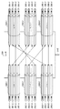
ここで、各ポートの信号線を時間軸方向に分割し、それぞれを仮想的な通信チャネル(以下、仮想チャネルと呼ぶ)として考える。図3に四分割の場合における仮想チャネルの概念図を示す。図3中、381、382、383、384、385、386はそれぞれ仮想チャネルである。各仮想チャネルの通信のスループットは、例えば元のポートの1/4ずつとなる。通信制御信号245は各クロックサイクルにおける、有効な仮想チャネルを指し示す。すなわち、例えば通信制御信号245の値が”1”の時、仮想チャネルは381−1、382−1、383−1、384−1、385−1、386−1がそれぞれ有効である。通信制御信号245の値が”2”の時、仮想チャネルは381−2、382−2、383−2、384−2、385−2、386−2がそれぞれ有効である。通信制御信号245の値が”3”の時、仮想チャネルは381−3、382−3、383−3、384−3、385−3、386−3がそれぞれ有効である。通信制御信号245の値が”4”の時、仮想チャネルは381−4、382−4、383−4、384−4、385−4、386−4がそれぞれ有効である。以降では、このように通信制御信号の値によって区別したクロックサイクルの集合をスロットと呼ぶ。
Here, the signal line of each port is divided in the time axis direction, and each is considered as a virtual communication channel (hereinafter referred to as a virtual channel). FIG. 3 shows a conceptual diagram of a virtual channel in the case of four divisions. In FIG. 3, 381, 382, 383, 384, 385, and 386 are virtual channels, respectively. The communication throughput of each virtual channel is, for example, 1/4 of the original port. The
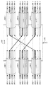
図4および図5を用いて、上記の通信制御信号245による制御を説明する。図4は通信制御信号245が”1”のスロットを示し、図5は通信制御信号245が”2”のスロットを示している。このように、各スロットにおける有効な仮想チャネルのみを切り出して考えると、図2と同等となる。すなわち、入力ポートの識別番号(識別情報)および入力スロット(データが入力されたクロックサイクルにおける通信制御信号の値)によって、出力ポートを選択できることを意味する。ただし、出力ポートの接続先が別のルータである場合、データを出力したスロットによって更にその先へルーティングされるため、出力するスロットもまた適切に選択する必要がある。したがって、入力ポートの識別番号および入力スロット(データが入力されたクロックサイクルにおける通信制御信号の値)によって、出力ポートおよび出力スロット(出力するクロックサイクルにおける通信制御信号の値)を選択する。これにより、本実施形態に係るルーティングを実現できる。なお、本実施形態では、データの入力スロットはデータの入力タイミングに相当し、出力スロットはデータの出力タイミングに相当する。
The control by the
この時、入力の仮想チャネルと出力の仮想チャネルとのマッピングは、図に示した例のように1対1である必要がある(使用しない仮想チャネルは開放でもよい)。例えば、1対多の接続(分岐)があるとすれば、出力先の選択に他の情報が必要であることを意味する。また、多対1の接続(統合)があるとすれば、データを同時に同じポートへ出力することになるので、データの衝突によるストールやデータの消失が生じる。逆に言えば、1対1の接続である時、入力データを所定の仮想チャネルに出力するだけであるため、送信先アドレスといったルーティングのための情報は不要であり、またデータの衝突がルータ内で生じないことを保証できる。 At this time, the mapping between the input virtual channel and the output virtual channel needs to be one-to-one as in the example shown in the figure (virtual channels not used may be open). For example, if there is a one-to-many connection (branch), it means that other information is required for selecting an output destination. Further, if there is a many-to-one connection (integration), data is output to the same port at the same time, so that a stall or data loss due to data collision occurs. In other words, when the connection is one-to-one, the input data is only output to a predetermined virtual channel, so there is no need for routing information such as a destination address, and there is no data collision in the router. Can be guaranteed not to occur.
(データ処理装置の構成要素)
次に、図1中の各要素の概略を述べる。外部インタフェース200は、図示していないメモリやプロセッサなどの外部モジュールと接続されている。画像処理パラメータや動作モード設定のための制御データ、および入力画素データ、出力画素データなどをこれらの外部モジュールとやり取りする。本実施形態では、一例として、入力画素データおよび出力画素データは、24ビット(RGB各8ビット)とする。
(Components of data processing device)
Next, the outline of each element in FIG. 1 will be described. The
ネットワークインタフェース220は、各IPコア210のプロトコルとルータ230のプロトコルとの差異、もしくは外部インタフェース200のプロトコルとルータ230のプロトコルとの差異を吸収する。なお、以降ではネットワークインタフェース220とルータ230を合わせてネットワークノードと呼ぶ。
The
ネットワークノード間の信号線はいずれも双方向に接続されている。信号線のビット幅は8ビットとする。8ビットを越えるデータを授受する場合は、送信側ネットワークインタフェースで8ビット単位に分割し、受信側ネットワークインタフェースで復元する。また、ルータ230−1からルータ230−2へ、ルータ230−2からルータ230−3へと繋がる方向(すなわち、時計回りの方向)を順方向と呼ぶ。ルータ230−2からルータ230−1へ、ルータ230−1からルータ230−8へと繋がる方向(すなわち、反時計回りの方向)を逆方向と呼ぶ。 All signal lines between the network nodes are connected bidirectionally. The bit width of the signal line is 8 bits. When data exceeding 8 bits is exchanged, it is divided into 8 bit units at the transmission side network interface and restored at the reception side network interface. Further, a direction (that is, a clockwise direction) connecting from the router 230-1 to the router 230-2 and from the router 230-2 to the router 230-3 is referred to as a forward direction. The direction connecting from the router 230-2 to the router 230-1 and from the router 230-1 to the router 230-8 (that is, the counterclockwise direction) is referred to as a reverse direction.
スロット制御部240は、データ処理装置100内で共通の通信制御信号を生成する。本実施形態では、通信制御信号は”0”、”1”、”2”、”3”、”4”のいずれかの値を取るとして説明する。通信制御信号は全てのネットワークノードへ同時に入力され、ネットワークノード間の通信は通信制御信号に同期して行われる。なお、通信制御信号の値が”0”の時は全ての通信を一時的に止める。このように、本実施形態では、各ルータ230に対して共通の制御信号を出力するため、実装が容易である。
The
(ルータ)
次に、データ処理装置100の各要素について詳説する。ルータ230は、複数のモジュール間のデータ伝送を中継するために、データの入力ポートおよび入力スロットごとに、データの出力ポートおよび出力スロットを処理開始前に設定可能な構成をとる。ルータ230の構成例を図6に示す。図6中、245はスロット制御部240で生成された通信制御信号、300はルーティングテーブル(対応情報)、310はデマルチプレクサである。また、320はスイッチ、330はスロットレジスタ、340はマルチプレクサ、350は入力ポート、360は出力ポートである。
(Router)
Next, each element of the
入力ポート350−1,2,3の入力ポート識別番号(識別情報)をそれぞれ”1”、”2”、”3”とする。出力ポート360−1,2,3の出力ポート識別番号(識別情報)をそれぞれ”1”、”2”、”3”とする。 The input port identification numbers (identification information) of the input ports 350-1, 2, and 3 are set to “1”, “2”, and “3”, respectively. The output port identification numbers (identification information) of the output ports 360-1, 2 and 3 are set to “1”, “2” and “3”, respectively.
ルーティングテーブル300は、データが入力されたポートの入力ポート識別番号と入力スロット(データが入力されたクロックサイクルにおける通信制御信号245の値)とを入力とする。そして、データを出力するポートの出力ポート識別番号301と出力スロット302(データを出力するクロックサイクルにおける通信制御信号245の値)とを出力する。このように、ルーティングテーブル300は、入力ポート及び入力スロットの識別情報と、出力ポート及び出力スロットの識別情報との対応関係を示す対応情報に該当し、予め記憶装置に記憶されている。なお、本実施形態では、入力スロットの識別情報は制御信号の値として特定される。
The routing table 300 receives an input port identification number and an input slot (value of the
ルーティングテーブル300の中身は処理開始前にファームウェアなどから設定する。この時、出力ポート識別番号と出力スロットの組合せが同じ複数のエントリが存在すると、前述した仮想チャネルのマッピングは多対1になる。そのため、出力ポート識別番号と出力スロットの組合せは排他である必要がある。 The contents of the routing table 300 are set from firmware or the like before the processing is started. At this time, if there are a plurality of entries having the same combination of the output port identification number and the output slot, the virtual channel mapping described above is many-to-one. Therefore, the combination of the output port identification number and the output slot needs to be exclusive.
ルータ230の他の部分は、このルーティングテーブル300を参照して、入力データを適切なポートから適切なタイミングで出力するための構成となっている。デマルチプレクサ310は、ルーティングテーブル300を参照して求められた出力ポート識別番号301を基に、入力データを出力するスイッチ320を決定する。例えば、出力ポート識別番号301が”1”であればスイッチ320−1、出力ポート識別番号301が”2”であればスイッチ320−2、出力ポート識別番号301が”3”であればスイッチ320−3へ入力データを送る。
The other part of the
スイッチ320は、図6に示したように三つの入力と四つの出力を持つ。入力はそれぞれデマルチプレクサ310に接続されており、出力はそれぞれスロットレジスタ330内のレジスタに接続されている。スイッチ320は、ルーティングテーブル300を参照して求められた出力スロット302を基に、入力データをスロットレジスタ330内の所定のレジスタへ格納する。 The switch 320 has three inputs and four outputs as shown in FIG. Each input is connected to the demultiplexer 310, and each output is connected to a register in the slot register 330. The switch 320 stores input data in a predetermined register in the slot register 330 based on the output slot 302 obtained by referring to the routing table 300.
スロットレジスタ330はデータ四つ分(計32ビット)を格納できるレジスタを備える。各レジスタは出力スロットが”1”、”2”、”3”、”4”の場合にそれぞれ対応しており、通信制御信号245がその値を指し示すまでは(すなわち、マルチプレクサ340に選択されて出力されるまでは)データを保持する。
The slot register 330 includes a register capable of storing four data (a total of 32 bits). Each register corresponds to the case where the output slot is “1”, “2”, “3”, “4”, respectively, until the
マルチプレクサ340は、スロットレジスタ330のうち、通信制御信号245が指し示すスロットに対応するレジスタに格納されているデータを出力ポート360へ出力する。ただし、通信制御信号245の値が”0”の場合、出力ポート360は前サイクルでの値を維持する。
The multiplexer 340 outputs the data stored in the register corresponding to the slot indicated by the
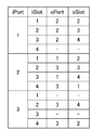
次に、ルータ230の動作について、例を用いて説明する。図7にルーティングテーブル300の設定例を示す。図7中、iPortは入力ポート識別番号、iSlotは入力スロット、oPortは出力ポート識別番号、oSlotは出力スロットをそれぞれ示している。この例では、1番の入力ポートへ入力されたデータは、2番の出力ポートへルーティングされる。2番の入力ポートへ入力されたデータは、1番と3番の出力ポートへ分岐してルーティングされる。3番の入力ポートへ入力されたデータは3番の出力ポートへルーティングされる。図7のように、出力スロットoSlotは入力スロットiSlotの値によって切り替えられる。
Next, the operation of the
この場合のタイミングチャート例を図8に示す。図8中、clockはシステムクロック、slotCtrlは入力スロットを示す通信制御信号245、iPort(N)はそれぞれ入力ポート識別番号が(N)である入力ポートである。regSlot(N)−(M)はそれぞれスロットレジスタ330−(N)内における出力スロットが(M)の場合に対応するレジスタ、oPort(N)はそれぞれ出力ポート識別番号が(N)である出力ポートである。d♯(♯は1,2,3,...,A,B,C,...,α,β,γ,...)はそれぞれ通信データを示している。ここで、♯は各データを区別するための記号である。
An example of a timing chart in this case is shown in FIG. In FIG. 8, clock is a system clock, slotCtrl is a
例えば、iPort1に入力されたデータd1は、入力ポート識別番号が”1”で、入力スロットが”1”であるため、ルーティングテーブルを参照して出力ポート識別番号は2、出力スロットは2と求められる。したがって、デマルチプレクサ310−1によりスイッチ320−2に送られ、更にスイッチ320−2により、スロットレジスタ330−2内における出力スロットが”2”の場合に対応するレジスタに格納される。これは、図8中のregSlot2−2に示されている。regSlot2−2に格納されたデータd1は、slotCtrlの値が”2”のクロックサイクルでマルチプレクサ340−2によりoPort2へ出力される。
For example, since the data d1 input to iPort1 has the input port identification number “1” and the input slot “1”, the output
また、例えば同時に入力されたデータdBとデータdαはどちらも出力ポート識別番号は”3”である。しかし、出力スロットが異なるため、データdBはregSlot3−3へ格納され、データdαはregSlot3−4へ格納される。マルチプレクサ340−3は出力スロットに対応するレジスタregSlot3−1,2,3,4の値を順次出力するので、dB、dαの順で出力される。このように、同一の出力ポートへ出力するデータであっても、異なる出力スロットを設定すれば、競合なく処理できる。 For example, both the data dB and the data dα input at the same time have an output port identification number “3”. However, since the output slots are different, data dB is stored in regSlot3-3, and data dα is stored in regSlot3-4. Since the multiplexer 340-3 sequentially outputs the values of the registers regSlot 3-1, 2, 3, and 4 corresponding to the output slots, the values are output in the order of dB and dα. Thus, even if data is output to the same output port, it can be processed without conflict if different output slots are set.
なお、図8に示したように、slotCtrlが”0”であるクロックサイクルにおいては、入力データは無効である。また、出力データは次サイクルまで保持される。 As shown in FIG. 8, input data is invalid in a clock cycle in which slotCtrl is “0”. The output data is held until the next cycle.
(スロット制御部)
スロット制御部240は通信制御信号245を生成し、ネットワークノード間の全通信を制御する。具体的には、複数のルータの各々に制御信号を出力して、ルータの経路選択を制御する。スロット制御部240の構成例を図9に示す。図9中、500はストール信号、510はスロットテーブル、520はマルチプレクサである。
(Slot control unit)
The
スロットテーブル510はS個のエントリを持つLUTである。ストール信号500がOFFの時、LUTのポインタは1からT(1≦T≦S)までの値をクロックサイクルに合わせて繰り返しインクリメントし、ストール信号500がONの時、LUTのポインタは前の値を維持する。ここで、Tはデータ処理装置100の動作周期をクロック単位で示す値である。各エントリの中身およびTは例えばファームウェアによりあらかじめ設定する。
The slot table 510 is an LUT having S entries. When the
マルチプレクサ520では、ストール信号500がOFFの時、LUTのポインタが指し示すエントリの値を出力し、ストール信号500がONの時、”0”を出力する。ストール信号500は、例えば外部インタフェース200が外部モジュールへデータを出力できない時、ONにする。これにより、データ処理装置100内の通信を全て一時的に止めることができる。このようにして、入力された制御信号の値が所定値の場合に、ルータ230に、データ伝送の中継を停止させることができる。
The
以上により、ストール信号500がOFFである通常動作時、通信制御信号245は周期Tサイクルで所定のパターンを繰り返す。したがって、各スロットの値がT以下のエントリに格納されている頻度は、各スロットのスループットを決定する。例えば、T=4であり、スロットテーブル510に”1”、”2”、”3”、”4”の順で格納されているとすれば、スロット1〜4のスループットはそれぞれ1/4[Byte/cycle]となる。例えば、T=6であり、スロットテーブル510に”1”、”2”、”3”、”1”、”2”、”4”の順で格納されているとすれば、スロット1〜4のスループットはそれぞれ1/3、1/3、1/6、1/6[Byte/cycle]となる。
As described above, during a normal operation in which the
また、前述したようにルータ230の動作は通信制御信号245に同期している。そのため、上記通信制御信号245の周期性により、ルータ230もまた周期Tサイクルで動作する。これにより、各ルータ230において全データが問題なく処理できるようにルーティングテーブル300などを設定するには、一周期分のデータのみを考慮するだけでよい。このようにして、スロット制御部240は、制御信号として、予め設定された複数の値を順に所定のタイミングで繰り返し出力する。したがって、スロット制御部240は、図9のように単純な構成で容易に実装することが可能である。
Further, as described above, the operation of the
(ネットワークインタフェース)
ネットワークインタフェース220は、ルータ230とIPコア210との間でビット幅やスループットの差異を吸収し、またルータ230へのデータ送出タイミングを調整する。ネットワークインタフェース220の構成例を図10に示す。図10中、410は統合部、430はFIFO(First−In, First−Out)、440は分割部、460はタイミング調整部である。
(Network interface)
The
ルータ230からネットワークインタフェース220へ入力されたデータは、まず統合部410へ送られる。統合部410では、入力データを必要に応じて複数回分蓄積し、IPコア210へ入力する形式へとまとめる。例えば、IPコア210への入力は画素データ24ビットおよび属性情報8ビットで計32ビットであるとする。これらのデータは他のIPコア210からルータ230を介して8ビットずつ順次入力される。この場合、ルータ230から入力されたデータを統合部410で4回分蓄積し、入力形式に統合してFIFO430へ渡す。
Data input from the
FIFO430では、IPコア210への入力スループットの変動を吸収する。ここで、入力スループットの変動とは、IPコア210へデータを入力できる間隔がIPコアの内部状態によって変化することを意味している。本実施形態では、入力スループットの変動を時間方向に平均化することにより、ネットワークインタフェース220への入力スループットは変動がないとして取り扱うことができるようにする。動作例を後で説明する。
The
分割部440では、IPコア210が出力するデータを分割し、ルータ230が扱うデータ形式に変換する。例えば、IPコア210が出力するデータが16ビットであるとすれば、データを転送単位である8ビットごとに分割し、2回に分けてタイミング調整部460へ送る。
The dividing
タイミング調整部460では、通信制御信号245の値が、あらかじめ設定された出力スロットと一致する場合にデータを出力する。一致しない場合は一致するまでデータを一時的に蓄積する。この出力スロットは、例えばファームウェアにより処理開始前に設定しておく。ネットワークインタフェース220からのデータを受け取るルータ230では、どのスロットでデータが入力されたかによってデータの宛先が決まる。よってこの出力スロットの値は、隣接するルータ230のルーティングテーブルに合わせる必要がある。
The
このように、FIFO430及びタイミング調整部460は、モジュールとルータとの間のスループットの違いを吸収するスループット緩衝手段として機能する。また、統合部410及び分割部440は、モジュールとルータとの間のビット幅の違いを吸収するビット幅緩衝手段として機能する。
As described above, the
入力スループットの変動の吸収について説明する。例えば、IPコア210として解像度変換モジュールを考える。出力スループットは1/2[pixel/cycle]で一定であるとする。画素の入力順序および出力順序はラスタ順とし、また縦方向および横方向の倍率はそれぞれ二倍とする。この時、画素数は入力の四倍になるので入力スループットは平均1/8[pixel/cycle]となる。ただし、一行の入力データに対し、画素数が二倍となった行が出力され、その後もう一行出力されるため、入力スループットは出力一行ごとに異なる。FIFO430は入力データをバッファリングし、この入力スループットの変動を隠蔽する。
Absorption of fluctuations in input throughput will be described. For example, consider a resolution conversion module as the
ネットワークインタフェース220の動作を示すタイミングチャートの例を図11に示す。図11中、clock はシステムクロック、input NI はルータ230からネットワークインタフェース220への入力、input IP はIPコア210への入力、output IP はIPコア210からの出力をそれぞれ示している。図11では各信号の値が High の時にデータの入力もしくは出力があることを示している。また、”Y−th line @Z” はデータが画像中においてY行目であり、そのスループットがZ[pixel/cycle]であることを示している。入力画像中のP行目(図11中、600)の入力に対し、出力画像中のQ行目(図11中、620)と(Q+1)行目(図11中、630)が出力される場合、(Q+1)行目の出力時には新たな入力データは必要ない(図11中、610)。このため、IPコア210への入力としては、スループットが1/4[pixel/cycle]の行と、それと同程度のサイクル数のブランク期間とが交互に必要となる。
An example of a timing chart showing the operation of the
このような入力スループットの変動を吸収するため、FIFO430では入力一行分を保持して遅延させる。すなわち、IPコアへの入力がP行目である時(図11中、600)、FIFO430では(P+1)行目の入力をバッファリングする(図11中、640)。これにより、スループットが1/8[pixel/cycle]の行が連続する input NI を、スループットが1/4[pixel/cycle]の行とブランク期間が交互に必要な input IP へ変換し、IPコア210へ供給する。input NI は入力スループットに変動がないので、ネットワークインタフェース220は入力スループットの変動がないモジュールとなる。
In order to absorb such fluctuations in input throughput, the
(動作例)
次に、本データ処理装置100の動作例を説明する。ルータ230の入力ポート識別番号1の入力ポートおよび出力ポート識別番号1の出力ポートは順方向に隣接するルータ230と接続されている。同様に、入力ポート識別番号2の入力ポートおよび出力ポート識別番号2の出力ポートは逆方向に隣接するルータ230と接続されている。入力ポート識別番号3の入力ポートおよび出力ポート識別番号3の出力ポートはネットワークインタフェース220と接続されている。
(Operation example)
Next, an operation example of the
既述したように、本データ処理装置100内の各ネットワークノード間の通信は、スロット制御部240が生成する通信制御信号245に同期して行われる。よって、各スロットの周期が各ネットワークノードの処理性能を超過すると、データの一部消失といった不具合を招く可能性がある。そのため、各IPコア210の処理スループットと処理順序とを勘案して、適切にスロットテーブル510の中身を設定する必要がある。
As described above, communication between the network nodes in the
例えば、各IPコア210の入力スループット、出力スループット、および処理順序が図12に示す通りであるとする。このときのデータの流れを図13に示す。1/6[pixel/cycle]のスループットで外部インタフェース200からデータがデータ処理装置100内に入力されたとする。この場合、IPコア210−2、IPコア210−4、IPコア210−3、IPコア210−5、IPコア210−6、IPコア210−7、IPコア210−8でそれぞれ順番に処理される。IPコア210−8ではスループット1/4[pixel/cycle]で出力され、外部インタフェース200からデータ処理装置100外に出力される。
For example, assume that the input throughput, output throughput, and processing order of each
この場合、スロット制御部240におけるスロットテーブル510のエントリには順に”1”、”2”、”3”、”4”を設定し、T=4として通信制御信号245を生成する。このようにすることで、ストール信号500がOFFの時、通信制御信号245は”1”、”2”、”3”、”4”を周期的に繰り返す。すなわち、各スロットはそれぞれスループット1/4[Byte/cycle]として実現される。一画素は24ビットであり、また一転送単位は8ビットなので、一画素の転送には三回の転送が必要となる。すなわち、各スロットのスループットは1/12[pixel/cycle]である。よって、外部インタフェース200からIPコア210−8まではスロットを二つ使用してデータを転送することで、1/6[pixel/cycle]のスループットを達成できる。IPコア210−8から外部インタフェース200へはスロットを三つ使用してデータを転送することで、1/4[pixel/cycle]のスループットを達成できる。
In this case, “1”, “2”, “3”, and “4” are sequentially set in the entries of the slot table 510 in the
ここで、通信制御信号の値が”1”の時のスロットをスロット1(図13中、s1と表記)、通信制御信号の値が”2”の時のスロットをスロット2(図13中、s2と表記)などと呼ぶこととする。例えば、ネットワークインタフェース220−1からネットワークインタフェース220−3までのデータパスではスロット1およびスロット3を使用してデータを転送している。ネットワークインタフェース220−3からルータ230−3までのデータパスではスロット2およびスロット4を使用している。これは、ルータ230−3における順方向出力のスロット1およびスロット3は既に使われているためである。ルータ230−4からネットワークインタフェース220−8までのデータパスではスロット1およびスロット3を使用している。ネットワークインタフェース220−8からネットワークインタフェース220−1まではスロット1、スロット2、およびスロット3を使用している。
Here, the slot when the value of the communication control signal is “1” is the slot 1 (indicated as s1 in FIG. 13), and the slot when the value of the communication control signal is “2” is the slot 2 (in FIG. 13, This will be referred to as “s2”. For example, the data path from the network interface 220-1 to the network interface 220-3
このようなルーティングを実現するためのルータ230内のルーティングテーブルの設定例を示す。ルータ230−1では、例えば図14(RT1)のテーブルのように設定する。これにより、順方向(すなわち、ルータ230−8)から入力されたスロット1、2、3のデータに対し、出力スロット1、2、3を用いて順次ネットワークインタフェース220−1へルーティングする。また、ネットワークインタフェース220−1から入力されたスロット1、3のデータに対し、出力スロット1、3を用いて順方向へ順次出力する。
A setting example of a routing table in the
ルータ230−2,5,6,7では、例えば図14(RT2)のテーブルのように設定する。これにより、順方向から入力されたスロット1、3のデータに対し、出力スロット1、3を用いて順次ネットワークインタフェース220−2,5,6,7へルーティングする。また、ネットワークインタフェース220−2,5,6,7から入力されたスロット1、3のデータに対し、出力スロット1、3を用いて順方向へ順次出力する。
The routers 230-2, 5, 6, and 7 are set as shown in the table of FIG. 14 (RT2). As a result, the data in the
ルータ230−3では、例えば図14(RT3)のテーブルのように設定する。これにより、順方向(すなわち、ルータ230−2)から入力されたスロット1、3のデータに対し、出力スロット1、3を用いて順方向(すなわち、ルータ230−4)へ順次出力する。また、逆方向(すなわち、ルータ230−4)から入力されたスロット1、3のデータに対し、出力スロット1、3を用いて順次ネットワークインタフェース220−3へルーティングする。また、ネットワークインタフェース220−3から入力されたスロット2、4のデータに対し、出力スロット2、4を用いて順方向(すなわち、ルータ230−4)へ順次出力する。
In the router 230-3, settings are made as shown in the table of FIG. 14 (RT3), for example. As a result, the data in
ルータ230−4では、例えば図14(RT4)のテーブルのように設定する。これにより、順方向(すなわち、ルータ230−3)から入力されたスロット1、3のデータに対し、出力スロット1、3を用いて順次ネットワークインタフェース220−4へルーティングする。また、順方向(すなわち、ルータ230−3)から入力されたスロット2、4のデータに対し、出力スロット1、3を用いて順方向(すなわち、ルータ230−5)へ順次出力する。また、ネットワークインタフェース220−4から入力されたスロット1、3のデータに対し、出力スロット1、3を用いて逆方向(すなわち、ルータ230−3)へ順次出力する。
In the router 230-4, settings are made as shown in the table of FIG. 14 (RT4). As a result, the data in the
ルータ230−8では、例えば図14(RT5)のテーブルのように設定する。これにより、順方向(すなわち、ルータ230−7)から入力されたスロット1、3のデータに対し、出力スロット1、3を用いて順次ネットワークインタフェース220−8へルーティングする。また、ネットワークインタフェース220−8から入力されたスロット1、2、3のデータに対し、出力スロット1、2、3を用いて順方向(すなわち、ルータ230−1)へ順次出力する。以上により、図12に示した要求仕様を満たすことができる。
In the router 230-8, settings are made as shown in the table of FIG. 14 (RT5), for example. As a result, the data in the
以上のように、本実施形態では、複数のルータ230の各々は、入力された制御信号の値を利用して、データ送出に用いる出力ポート及び出力タイミングを決定する。このため、伝送データにルーティングを制御するための情報を付加する必要がなく、効率的なデータ伝送が可能になる。
As described above, in the present embodiment, each of the plurality of
また、ルータ230はルーティングテーブル300を参照して、データ送出に用いる出力ポート及び出力タイミングを決定する。このため、構成が複雑でなく、実装が容易である。
Further, the
以上説明したように、本実施形態ではスロット制御部が生成する通信制御信号に同期して各ネットワークノード間の通信を行う。これにより、通信データにルーティングのための情報を付加することなくデータ通信を実現できる。したがって、オーバーヘッドが低減されたデータ通信技術の提供が可能である。 As described above, in the present embodiment, communication between network nodes is performed in synchronization with the communication control signal generated by the slot control unit. Thus, data communication can be realized without adding information for routing to communication data. Therefore, it is possible to provide a data communication technique with reduced overhead.
なお、本実施形態では、通信制御信号245の値が”0”の場合は通信を一時停止させ、他の値の場合は通常動作であったが、他にも特定用途のスロットがあってもよい。例えば、IPコア210のパラメータを設定するためのスロットがあってもよい。また、本実施形態においては通信制御信号245の値を”0”、”1”、”2”、”3”、”4”の五種としたが、任意の数で実現できる。通信制御信号245の値をワンホットで表現してもよい。
In the present embodiment, when the value of the
さらに、IPコア210はデータの通信制御信号の値をデータ処理時のパラメータとして用いてもよい。例えばフィルタ演算を行うIPコアで、スロットに応じてフィルタの係数を切り替えてもよい。
Further, the
入力を画像データとし、IPコア210で画像処理を行うとしたが、任意の処理内容で実現できる。例えば、音声データや文書データ、アプリケーション・プログラム等でもよい。
Although the input is assumed to be image data and the image processing is performed by the
また、ルータ230におけるルーティングには入力ポート識別番号と入力スロットのみを用いたが、他の情報と併用してもよい。例えば、入力ポート識別番号および入力スロットに加え、データに付随する情報を参照してもよい。
Further, although only the input port identification number and the input slot are used for routing in the
また、ネットワークインタフェース220は上記で説明した構成に限らない。例えば、IPコア210の入力スループットに変動が無ければFIFO430は無くてもよい。IPコア210のビット幅がルータ230のビット幅以下であれば統合部410および分割部440は無くてもよい。
The
前述の構成では八つのルータをリング状に接続したが、これに限られるわけではない。次に図15のようなトポロジで構成した場合について説明する。図15ではルータ230−2、3、4、5は四入力四出力であるが、其々の構成は前述の構成と同様である。図15のルータは、スロット数がAで、入力ポート数がB、出力ポート数がCである場合、以下を備えている。
・エントリ数が(A×B)であるルーティングテーブル。
・C出力のB個のデマルチプレクサ。
・B入力A出力のC個のスイッチ。
・A個分のデータが格納可能なC個のスロットレジスタ。
・A入力のC個のマルチプレクサ。
In the above configuration, eight routers are connected in a ring shape, but the present invention is not limited to this. Next, a case where the topology is as shown in FIG. 15 will be described. In FIG. 15, the routers 230-2, 3, 4, and 5 have four inputs and four outputs, but their configurations are the same as those described above. The router in FIG. 15 includes the following when the number of slots is A, the number of input ports is B, and the number of output ports is C.
A routing table whose number of entries is (A × B).
• B demultiplexers with C outputs.
・ C switches with B input and A output.
-C slot registers that can store A data.
-C multiplexers with A input.
この構成における動作例を図16に示す。このように、二つの外部インタフェースから異なるデータシーケンスが同時に入力されても、各ルータ230のルーティングテーブルにおいて出力ポート番号と出力スロットの組合せが排他である限り問題なく処理できる。このように、図15の構成ではトポロジを限定しないので、アプリケーションに応じて容易に構成を変更できる。
An example of operation in this configuration is shown in FIG. As described above, even if different data sequences are simultaneously input from the two external interfaces, processing can be performed without any problem as long as the combination of the output port number and the output slot is exclusive in the routing table of each
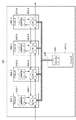
前述の説明ではIPコア間でのデータ通信について説明したが、次にマルチプロセッサシステムに係る構成を説明する。構成例を図17に示す。図17中、800はプロセッサである。プロセッサ800は全て同じプロセッサでなくてもよい。 In the above description, data communication between IP cores has been described. Next, a configuration related to a multiprocessor system will be described. A configuration example is shown in FIG. In FIG. 17, reference numeral 800 denotes a processor. The processors 800 need not all be the same processor.
スロット制御プロセス830は、プロセッサ800上で通信制御信号245を生成する関数である。画像処理プロセス810は、プロセッサ800上で各種画像処理を行う関数である。ルーティングプロセス820は、プロセッサ800上で隣接するプロセッサとデータを通信する関数である。データを受け取ったタイミングにおける通信制御信号245の値および通信データが入力されたポートに割り振られた入力ポート識別番号により、データの出力ポートおよびデータを出力するタイミングを決定する。ここでのポートとはハードウェアとして実装されたポートでもよいし、ソフトウェアで実装されたポートでもよい。以上のような構成により、データ通信を実現できる。
The
以上説明したように、マルチプロセッサシステムにおいても、通信のオーパヘッドを低減することができる。なお、マルチプロセッサの構成の上記実施形態で述べた構成に限らない。例えば、スロット制御プロセス830と画像処理プロセス810が同じプロセッサ上で動作してもよい。複数のスロット制御プロセス830が複数のプロセッサ上で並列に動作し、それらを同期する機構があってもよい。
As described above, communication overhead can be reduced even in a multiprocessor system. The configuration of the multiprocessor is not limited to the configuration described in the above embodiment. For example, the
前述の構成ではスロット制御部が通信制御信号を生成し、各ネットワークノードに配信した。このため、スロット制御部を中心として放射状に通信制御信号を配線する必要がある。よってネットワークノードの数が大きくなると、配線が困難になる可能性がある。本実施例では、各ネットワークノードがそれぞれ通信制御信号を自己生成する。 In the above configuration, the slot control unit generates a communication control signal and distributes it to each network node. For this reason, it is necessary to wire communication control signals radially centering on the slot control unit. Therefore, when the number of network nodes increases, wiring may become difficult. In this embodiment, each network node self-generates a communication control signal.
通信制御信号は通常、周期的であるため、各ネットワークノード間で同期が取れていれば(通信制御信号の値が同じであれば)、前述の構成と同等の機能を実現できる。ただし、通信を止める場合(すなわち通信制御信号の値を0とする場合)に用いるストール信号はネットワークノード間でリレーする。これにより、ストールのタイミングをも同期できるようにする。 Since the communication control signal is usually periodic, if the network nodes are synchronized (if the value of the communication control signal is the same), a function equivalent to the above-described configuration can be realized. However, a stall signal used when communication is stopped (that is, when the value of the communication control signal is set to 0) is relayed between network nodes. As a result, the stall timing can be synchronized.
構成例を図18に示す。図示したように、ストール発行部940をリング状に接続されたルータ間の1ノードとして接続する。図中、縦縞の矢印はストール信号950の伝搬を示している。ストール信号はストール発行部940から1サイクルに1ノードずつ順番にリレーされていく。すなわち図18の場合は、一番遠いネットワークインタフェース920−4および920−5まで5サイクルかかる。
A configuration example is shown in FIG. As illustrated, the
ストールはネットワークノード間で同期させる必要があるため、ストール発行部940からストール信号が発行されてから5サイクル後に全通信を一時停止させる事とする。例えばルータ930−1はストール信号を受け取ってから5サイクル後に通信を一時停止させる。ルータ930−3はストール信号を受け取ってから3サイクル後に通信を一時停止させる。ネットワークインタフェース920−4はストール信号を受け取って次のサイクルで通信を一時停止させる。このようにする事でストールを同一のタイミングとする事ができる。
Since stalls need to be synchronized between network nodes, all communications are temporarily stopped 5 cycles after the stall signal is issued from the
図19にルータの構成例を示す。図示したように、この場合ネットワークノードは図9で示したスロット制御部の機能を内包する。これにより、通信制御信号245を内部で生成する。ストール信号950はタイマ960へ入力され、ここで所定のサイクル数待たされる。このサイクル数は前述したように、ストール発行部940への距離によって異なる。なお、ネットワークインタフェースも同様である。以上により、各ネットワークノード間で生成する通信制御信号の値は同一となり、前述の制御と同様の制御が可能になる。
FIG. 19 shows a configuration example of the router. As shown in the figure, in this case, the network node includes the function of the slot control unit shown in FIG. Thereby, the
以上説明したように、各ネットワークノード内部で通信制御信号を生成させることもできる。この場合ストールを同期させるための機構が必要になる。 As described above, a communication control signal can be generated inside each network node. In this case, a mechanism for synchronizing the stall is required.
なお、ネットワークノードそれぞれが通信制御信号を生成部したが、いくつかのネットワークノードでこれを共有しても良い。(なお全てのネットワークノードで共有すると前述の構成と同様となる。)ストール発行部は複数あっても良い。 Although each network node generates a communication control signal, it may be shared by several network nodes. (It is the same as the above-described configuration when shared by all network nodes.) There may be a plurality of stall issuing units.
上記の各構成によれば、ルータは通信制御信号の値を参照してルーティングを行う。これにより、通信データに付加する情報の情報量を低減させることができるため、データ通信効率の向上が可能である。例えば、ルータ間におけるデータ通信の帯域幅が32[bit/cycle]だと仮定する。上記従来の方法の場合、通信データに付加する情報が16ビットだとすれば、1サイクルに転送できる通信データは最大で16ビットである。一方、本発明によれば1サイクルに転送できる通信データは最大で32ビットとなる。 According to each configuration described above, the router performs routing with reference to the value of the communication control signal. As a result, the amount of information added to the communication data can be reduced, so that the data communication efficiency can be improved. For example, it is assumed that the bandwidth of data communication between routers is 32 [bit / cycle]. In the case of the conventional method, if the information added to the communication data is 16 bits, the communication data that can be transferred in one cycle is a maximum of 16 bits. On the other hand, according to the present invention, the maximum number of communication data that can be transferred in one cycle is 32 bits.
また、本発明は、以下の処理を実行することによっても実現される。即ち、上述した実施形態の機能を実現するソフトウェア(プログラム)を、ネットワーク又は各種記憶媒体を介してシステム或いは装置に供給し、そのシステム或いは装置のコンピュータ(またはCPUやMPU等)がプログラムを読み出して実行する処理である。 The present invention can also be realized by executing the following processing. That is, software (program) that realizes the functions of the above-described embodiments is supplied to a system or apparatus via a network or various storage media, and a computer (or CPU, MPU, or the like) of the system or apparatus reads the program. It is a process to be executed.
Claims (9)
前記入力データを転送するためのタイミングで制御信号を出力する制御手段と、
複数の入力ポートと、複数の出力ポートと、複数のデマルチプレクサと、記憶手段であって、前記入力ポートの識別情報、前記入力ポートへの入力タイミングの前記制御信号の値、前記出力ポートの識別情報及び前記出力ポートへの出力タイミングの前記制御信号の値、の対応関係を示す対応情報を記憶する記憶手段とを備え、前記複数のモジュール間でのデータ転送をする複数のルータと、
を備え、
前記デマルチプレクサは、前記入力ポートへの入力タイミングの前記制御信号に対応して、前記複数の入力ポートの1つを前記対応情報に基づいて前記複数の出力ポートの1つに関連付け、
前記制御信号は前記データとは異なる別のものであり、
前記制御手段は各ルータに共通信号としてクロックサイクルごとに値を切り替えて前記制御信号を出力し、前記ルータは、前記制御手段が出力した制御信号の値が前記対応情報に示された前記出力ポートへの出力タイミングの前記制御信号の値のときに前記関連付けた出力ポートに前記入力データを出力する
ことを特徴とするデータ処理装置。 A plurality of modules for performing data processing based on input data;
Control means for outputting a control signal at a timing for transferring the input data;
A plurality of input ports, a plurality of output ports, a plurality of demultiplexers , and storage means, the identification information of the input port, the value of the control signal of the input timing to the input port, the identification of the output port Storage means for storing correspondence information indicating a correspondence relationship between the information and the value of the control signal of the output timing to the output port, and a plurality of routers for transferring data between the plurality of modules;
With
The demultiplexer, in response to said control signal input timing to the input port, associating one of the plurality of input ports to one of said plurality of output ports based on the correspondence information,
The control signal is different from the data;
The control means switches the value for each clock cycle as a common signal to each router and outputs the control signal, and the router outputs the control signal value output by the control means in the output port indicated in the correspondence information data processing apparatus, characterized in that you output the input data the output port associated with the time value of the control signal output timing to.
前記レジスタは前記出力ポートへの出力タイミングの前記制御信号の値に対応した出力データを保持する
ことを特徴とする請求項1に記載のデータ処理装置。 Each of the plurality of routers further includes a register for each of the output ports,
The data processing apparatus according to claim 1, wherein the register holds output data corresponding to a value of the control signal at an output timing to the output port .
複数のモジュールが、入力データに基づいてデータ処理を実施する工程と、
制御手段が、前記入力データを転送するためのタイミングで制御信号を出力する工程と、
複数の入力ポートと、複数の出力ポートと、複数のデマルチプレクサと、記憶手段であって、前記入力ポートの識別情報、前記入力ポートへの入力タイミングの前記制御信号の値、前記出力ポートの識別情報及び前記出力ポートへの出力タイミングの前記制御信号の値、の対応関係を示す対応情報を記憶する記憶手段とを備えた複数のルータが、前記複数のモジュール間でのデータ転送をする工程と、
を有し、
前記デマルチプレクサは、前記入力ポートへの入力タイミングの前記制御信号に対応して、前記複数の入力ポートの1つを前記対応情報に基づいて前記複数の出力ポートの1つに関連付け、
前記制御信号は、前記データとは異なる別のものであり、
前記制御手段は、各ルータに共通信号としてクロックサイクルごとに値を切り替えて前記制御信号を出力し、前記ルータは、前記制御手段が出力した制御信号の値が前記対応情報に示された前記出力ポートへの出力タイミングの前記制御信号の値のときに前記関連付けた出力ポートに前記入力データを出力する
ことを特徴とするデータ処理装置の制御方法。 A method for controlling a data processing apparatus, comprising:
A plurality of modules performing data processing based on input data;
A step in which the control means outputs a control signal at a timing for transferring the input data;
A plurality of input ports, a plurality of output ports, a plurality of demultiplexers , and storage means, the identification information of the input port, the value of the control signal of the input timing to the input port, the identification of the output port A plurality of routers comprising storage means for storing correspondence information indicating a correspondence relationship between information and a value of the control signal at an output timing to the output port, and transferring data between the plurality of modules; ,
Have
The demultiplexer associates one of the plurality of input ports with one of the plurality of output ports based on the correspondence information in response to the control signal of input timing to the input port;
The control signal is different from the data;
The control means outputs the control signal by switching the value for each clock cycle as a common signal to each router, and the router outputs the control signal value output by the control means in the correspondence information. the method of the data processing apparatus, characterized in that you output said input data to said output port associated with the time value of the control signal output timing to the port.
Priority Applications (2)
| Application Number | Priority Date | Filing Date | Title |
|---|---|---|---|
| JP2010264296A JP5753372B2 (en) | 2009-12-22 | 2010-11-26 | Data processing apparatus and control method thereof |
| US12/968,694 US9071504B2 (en) | 2009-12-22 | 2010-12-15 | Data processing apparatus and method of controlling the same |
Applications Claiming Priority (3)
| Application Number | Priority Date | Filing Date | Title |
|---|---|---|---|
| JP2009291398 | 2009-12-22 | ||
| JP2009291398 | 2009-12-22 | ||
| JP2010264296A JP5753372B2 (en) | 2009-12-22 | 2010-11-26 | Data processing apparatus and control method thereof |
Publications (3)
| Publication Number | Publication Date |
|---|---|
| JP2011151786A JP2011151786A (en) | 2011-08-04 |
| JP2011151786A5 JP2011151786A5 (en) | 2014-01-16 |
| JP5753372B2 true JP5753372B2 (en) | 2015-07-22 |
Family
ID=44151005
Family Applications (1)
| Application Number | Title | Priority Date | Filing Date |
|---|---|---|---|
| JP2010264296A Active JP5753372B2 (en) | 2009-12-22 | 2010-11-26 | Data processing apparatus and control method thereof |
Country Status (2)
| Country | Link |
|---|---|
| US (1) | US9071504B2 (en) |
| JP (1) | JP5753372B2 (en) |
Families Citing this family (5)
| Publication number | Priority date | Publication date | Assignee | Title |
|---|---|---|---|---|
| US8812727B1 (en) * | 2011-06-23 | 2014-08-19 | Amazon Technologies, Inc. | System and method for distributed load balancing with distributed direct server return |
| WO2015194072A1 (en) * | 2014-06-18 | 2015-12-23 | 日本電気株式会社 | Relay apparatus, communication apparatus, management apparatus, relay method and relay program |
| CN111684769B (en) * | 2017-11-06 | 2023-03-24 | 思想系统公司 | Network system including matching processing unit of table-based action |
| US11263158B2 (en) | 2018-02-22 | 2022-03-01 | Pensando Systems Inc. | Programmable computer IO device interface |
| US11134030B2 (en) * | 2019-08-16 | 2021-09-28 | Intel Corporation | Device, system and method for coupling a network-on-chip with PHY circuitry |
Family Cites Families (14)
| Publication number | Priority date | Publication date | Assignee | Title |
|---|---|---|---|---|
| JPH06500655A (en) * | 1990-10-03 | 1994-01-20 | スィンキング マシンズ コーポレーション | parallel computer system |
| TW357521B (en) * | 1996-12-26 | 1999-05-01 | Dsc Telecom Lp | Data transfer system and method for distributed digital cross-connect system |
| US6570872B1 (en) * | 1999-04-06 | 2003-05-27 | Nortel Networks Limited | Self-configuring distributed switch |
| US6693914B1 (en) * | 1999-10-01 | 2004-02-17 | Stmicroelectronics, Inc. | Arbitration mechanism for packet transmission |
| US7266122B1 (en) * | 2002-11-27 | 2007-09-04 | Genband Inc. | System and method for allocating bandwidth in a communications environment |
| JP4199994B2 (en) * | 2002-12-09 | 2008-12-24 | 株式会社日立製作所 | Signal communication apparatus and signal communication system |
| KR100493096B1 (en) * | 2003-05-07 | 2005-06-02 | 삼성전자주식회사 | Apparatus and Method of Fast Optical Routing |
| JP4365672B2 (en) * | 2003-12-04 | 2009-11-18 | 株式会社日立製作所 | Packet communication node equipment |
| KR20040052921A (en) * | 2004-05-17 | 2004-06-23 | 김기천 | Clock synchronizer for distributed traffic control |
| JP4332079B2 (en) * | 2004-07-01 | 2009-09-16 | 株式会社日立製作所 | Module type packet communication node equipment |
| JP4373322B2 (en) * | 2004-12-22 | 2009-11-25 | 日本電信電話株式会社 | Data transfer network and network control device |
| ATE523990T1 (en) * | 2005-04-21 | 2011-09-15 | Koninkl Philips Electronics Nv | INTEGRATED CIRCUIT WITH DATA COMMUNICATIONS NETWORK AND METHOD FOR DESIGNING INTEGRATED CIRCUITS |
| US7599289B2 (en) * | 2005-05-13 | 2009-10-06 | Lockheed Martin Corporation | Electronic communication control |
| US8249067B2 (en) * | 2008-02-27 | 2012-08-21 | Broadcom Corporation | Separation of fabric and packet processing source in a system |
-
2010
- 2010-11-26 JP JP2010264296A patent/JP5753372B2/en active Active
- 2010-12-15 US US12/968,694 patent/US9071504B2/en active Active
Also Published As
| Publication number | Publication date |
|---|---|
| JP2011151786A (en) | 2011-08-04 |
| US9071504B2 (en) | 2015-06-30 |
| US20110149985A1 (en) | 2011-06-23 |
Similar Documents
| Publication | Publication Date | Title |
|---|---|---|
| JP5753372B2 (en) | Data processing apparatus and control method thereof | |
| JP4808513B2 (en) | System-on-chip global asynchronous communication architecture | |
| US8954174B2 (en) | Method and device to process digital media streams | |
| JP3783731B2 (en) | Fast switching network structure | |
| CN101159687B (en) | System, device and method of multi-channel communication transmitting data | |
| JP2002512485A (en) | Method and apparatus for dynamic synchronous transfer mode in a dual ring topology | |
| EP1125386A1 (en) | Time-synchronized multi-layer network switch for providing quality of service guarantees in computer networks | |
| JP5895153B2 (en) | Interface device and bus system | |
| KR20070037634A (en) | Flexray communication component | |
| JP2000224213A (en) | Communication network, master set, slave set, multiplexer and exchange configuring the communication network | |
| WO2010104033A1 (en) | Interprocessor communication system and communication method, network switch, and parallel computing system | |
| JP5821624B2 (en) | Communication control device, parallel computer system, and communication control method | |
| US20130250954A1 (en) | On-chip router and multi-core system using the same | |
| JP6847334B2 (en) | Network equipment, network systems, network methods, and network programs | |
| JP4994280B2 (en) | Route change type network device and system | |
| JP2006109258A (en) | Communication method and communication apparatus | |
| TW201109940A (en) | A method for dynamical adjusting channel direction and network-on-chip architecture thereof | |
| JP2024505262A (en) | Controlling a network of data processing devices for a quantum computer | |
| JP2011013919A (en) | Transfer rate setting method, data transfer apparatus and information processing system | |
| JP6029329B2 (en) | Synchronous network switch | |
| JP5374290B2 (en) | Network relay device | |
| JP2006114028A (en) | Apparatus for interconnecting multiple devices to synchronous device | |
| JP4944377B2 (en) | Linearly expandable distribution router device | |
| JP2001094598A (en) | Server device, server node device, client node device, and network system | |
| JP2009188479A (en) | Network processing apparatus |
Legal Events
| Date | Code | Title | Description |
|---|---|---|---|
| A521 | Request for written amendment filed |
Free format text: JAPANESE INTERMEDIATE CODE: A523 Effective date: 20131126 |
|
| A621 | Written request for application examination |
Free format text: JAPANESE INTERMEDIATE CODE: A621 Effective date: 20131126 |
|
| A977 | Report on retrieval |
Free format text: JAPANESE INTERMEDIATE CODE: A971007 Effective date: 20140619 |
|
| A131 | Notification of reasons for refusal |
Free format text: JAPANESE INTERMEDIATE CODE: A131 Effective date: 20140718 |
|
| A521 | Request for written amendment filed |
Free format text: JAPANESE INTERMEDIATE CODE: A523 Effective date: 20140916 |
|
| A02 | Decision of refusal |
Free format text: JAPANESE INTERMEDIATE CODE: A02 Effective date: 20141215 |
|
| A521 | Request for written amendment filed |
Free format text: JAPANESE INTERMEDIATE CODE: A523 Effective date: 20150310 |
|
| A911 | Transfer to examiner for re-examination before appeal (zenchi) |
Free format text: JAPANESE INTERMEDIATE CODE: A911 Effective date: 20150318 |
|
| TRDD | Decision of grant or rejection written | ||
| A01 | Written decision to grant a patent or to grant a registration (utility model) |
Free format text: JAPANESE INTERMEDIATE CODE: A01 Effective date: 20150424 |
|
| A61 | First payment of annual fees (during grant procedure) |
Free format text: JAPANESE INTERMEDIATE CODE: A61 Effective date: 20150522 |
|
| R151 | Written notification of patent or utility model registration |
Ref document number: 5753372 Country of ref document: JP Free format text: JAPANESE INTERMEDIATE CODE: R151 |