JP5753088B2 - Disinfectant transfer port - Google Patents
Disinfectant transfer port Download PDFInfo
- Publication number
- JP5753088B2 JP5753088B2 JP2011530289A JP2011530289A JP5753088B2 JP 5753088 B2 JP5753088 B2 JP 5753088B2 JP 2011530289 A JP2011530289 A JP 2011530289A JP 2011530289 A JP2011530289 A JP 2011530289A JP 5753088 B2 JP5753088 B2 JP 5753088B2
- Authority
- JP
- Japan
- Prior art keywords
- assembly
- beta
- alpha
- cover
- product
- Prior art date
- Legal status (The legal status is an assumption and is not a legal conclusion. Google has not performed a legal analysis and makes no representation as to the accuracy of the status listed.)
- Active
Links
Images


Classifications
-
- A—HUMAN NECESSITIES
- A61—MEDICAL OR VETERINARY SCIENCE; HYGIENE
- A61L—METHODS OR APPARATUS FOR STERILISING MATERIALS OR OBJECTS IN GENERAL; DISINFECTION, STERILISATION OR DEODORISATION OF AIR; CHEMICAL ASPECTS OF BANDAGES, DRESSINGS, ABSORBENT PADS OR SURGICAL ARTICLES; MATERIALS FOR BANDAGES, DRESSINGS, ABSORBENT PADS OR SURGICAL ARTICLES
- A61L2/00—Methods or apparatus for disinfecting or sterilising materials or objects other than foodstuffs or contact lenses; Accessories therefor
- A61L2/26—Accessories or devices or components used for biocidal treatment
-
- A—HUMAN NECESSITIES
- A61—MEDICAL OR VETERINARY SCIENCE; HYGIENE
- A61L—METHODS OR APPARATUS FOR STERILISING MATERIALS OR OBJECTS IN GENERAL; DISINFECTION, STERILISATION OR DEODORISATION OF AIR; CHEMICAL ASPECTS OF BANDAGES, DRESSINGS, ABSORBENT PADS OR SURGICAL ARTICLES; MATERIALS FOR BANDAGES, DRESSINGS, ABSORBENT PADS OR SURGICAL ARTICLES
- A61L2/00—Methods or apparatus for disinfecting or sterilising materials or objects other than foodstuffs or contact lenses; Accessories therefor
- A61L2/02—Methods or apparatus for disinfecting or sterilising materials or objects other than foodstuffs or contact lenses; Accessories therefor using physical phenomena
- A61L2/04—Heat
- A61L2/06—Hot gas
- A61L2/07—Steam
-
- Y—GENERAL TAGGING OF NEW TECHNOLOGICAL DEVELOPMENTS; GENERAL TAGGING OF CROSS-SECTIONAL TECHNOLOGIES SPANNING OVER SEVERAL SECTIONS OF THE IPC; TECHNICAL SUBJECTS COVERED BY FORMER USPC CROSS-REFERENCE ART COLLECTIONS [XRACs] AND DIGESTS
- Y10—TECHNICAL SUBJECTS COVERED BY FORMER USPC
- Y10T—TECHNICAL SUBJECTS COVERED BY FORMER US CLASSIFICATION
- Y10T137/00—Fluid handling
- Y10T137/8593—Systems
Landscapes
- Health & Medical Sciences (AREA)
- Epidemiology (AREA)
- Life Sciences & Earth Sciences (AREA)
- Animal Behavior & Ethology (AREA)
- General Health & Medical Sciences (AREA)
- Public Health (AREA)
- Veterinary Medicine (AREA)
- Apparatus For Disinfection Or Sterilisation (AREA)
- Quick-Acting Or Multi-Walled Pipe Joints (AREA)
Description
本出願は、米国以外全ての指定国の出願人である米国企業Delaware Capital Formation Inc.,ならびに米国のみの指定国の出願人である米国民Richard H.Adams、米国民Miles A.Closeおよび米国民Amos E.Averyにより、2009年10月5日にPCT国際特許出願として出願されており、2008年10月3日出願の米国特許出願第12/245,603号の優先権を主張し、その内容は参考文献として本明細書に援用される。 This application is filed by US company Delaware Capital Formation Inc., an applicant in all designated countries other than the United States. , As well as US citizen Richard H. Adams, American citizen Miles A. Close and American citizen Amos E. Filed by Avery on Oct. 5, 2009 as a PCT international patent application and claimed the priority of US patent application Ser. No. 12 / 245,603 filed Oct. 3, 2008, the contents of which are incorporated by reference As incorporated herein by reference.
移送ポート装置および方法によって、汚染された環境から清浄な環境を分離する分離壁の移送ポートを通した、比較的汚染された環境から比較的清浄な環境への殺菌液の非汚染移送が可能となる。 Transfer port apparatus and method allows non-contaminated transfer of sterilizing liquid from a relatively contaminated environment to a relatively clean environment through a transfer port in a separation wall that separates the clean environment from the contaminated environment Become.
大量の殺菌液プロダクトは、エンドユーザに分配するために、小容器に移さなければならない。移送プロセスは、プロダクトタンクをプロダクトで充填することにより始まる。殺菌液プロダクトは、プロダクトタンク内側から、プロダクトホースの内側を通って、そしてプロダクト管の内側を通って搬送される。プロダクト管は、移送ポート装置の一部である。殺菌液は、プロダクト管から、充填ホースへ、そして、充填機器へ搬送され、続いて、数多くの小容器へ充填される。 Large volumes of disinfectant product must be transferred to small containers for distribution to end users. The transfer process begins by filling the product tank with product. The sterilizing liquid product is conveyed from the inside of the product tank, through the inside of the product hose, and through the inside of the product pipe. The product tube is part of the transfer port device. The sterilizing liquid is conveyed from the product tube to the filling hose and to the filling equipment, and subsequently filled into a number of small containers.
殺菌液プロダクトが充填される前、プロダクトタンク、プロダクトホースおよびプロダクト管の内部は、生物剤およびダストのような不活性(nonviable)粒子により汚染される恐れがある。生物剤と不活性粒子は両方共、プロダクトタンクおよび関連する管を充填する前に、それらが取り除かれないと、殺菌液プロダクトの殺菌性を損なうであろう。殺菌液移送ポートは、ベータ組立体および殺菌ドッキングカバーの使用によりプロダクトタンクおよび関連の管を蒸気クリーニングすることにより、汚染を除去する。 Before the sterilizing liquid product is filled, the interior of the product tank, product hose and product tube can be contaminated by non-viable particles such as biological agents and dust. Both biological agents and inert particles will impair the disinfectability of the disinfectant product if they are not removed before filling the product tank and associated tubing. The sterilant transfer port removes contamination by steam cleaning the product tank and associated tubing through the use of a beta assembly and sterilization docking cover.
さらに、比較的汚れた環境だと、不活性粒子により、清浄な環境が汚染される可能性がある。小容器への充填がなされる清浄な環境の汚染を防ぐには、プロダクトタンクが位置する汚れた環境と、清浄な環境との間に物理的障壁を挿入する。障壁は、殺菌液移送ポートのアルファ組立体と、それに連携されたベータ組立体で構成される。 Further, in a relatively dirty environment, the clean environment can be contaminated by inert particles. To prevent contamination of the clean environment where the small container is filled, a physical barrier is inserted between the clean environment where the product tank is located and the clean environment. The barrier is comprised of an alpha assembly of a sterilant transfer port and a beta assembly associated therewith.
従って、殺菌液移送ポート(「SLTP」)は、安全、迅速、経済的かつ費用効率の高い(i)殺菌液プロダクトが移されるプロダクト容器および管の殺菌、および(ii)あまり清浄でない環境からの清浄な環境の分離を提供する。 Thus, the sterilant transfer port ("SLTP") is safe, fast, economical and cost effective (i) sterilization of product containers and tubes to which sterilant product is transferred, and (ii) from less clean environments. Provide clean environment separation.
プロダクトタンク202(プロダクト室205に位置する)の殺菌された内部から充填機器209(充填室204に位置する)への液体プロダクトの移送は、殺菌が完了していれば、極めて単純な作業である。殺菌液プロダクトの移送では、分離壁201の移送ポート201bを通る。
Transfer of the liquid product from the sterilized interior of the product tank 202 (located in the product chamber 205) to the filling device 209 (located in the filling chamber 204) is a very simple task once sterilization is complete. . In the transfer of the sterilizing liquid product, it passes through the transfer port 201b of the
SLTPのアルファ組立体はまた、あまり清浄でない環境のプロダクト室205を、清浄な環境の充填室204から分離している。プロダクト室205は、大量の殺菌液プロダクトを封じ込めるために、プロダクトタンク202を囲んでいる。充填室204は、少量のプロダクトの商業包装のために、充填機器209を囲んでいる。典型的に、プロダクト室205は、充填室204(例えば、クラス100環境)より、低レベルの清浄度(例えば、クラス10,000環境)である。
The SLTP alpha assembly also separates the less clean environment product chamber 205 from the clean
SLTPを用いる一例は、調剤である。調剤においては、生物剤を、プロダクト室205から充填室204に動かす必要が生じ、比較的少量のプロダクトが、分配のために、無菌バイアルおよびシリンジ等の容器に移される。
One example using SLTP is dispensing. In dispensing, the biological agent needs to be moved from the product chamber 205 to the
一実施形態において、SLTPは、アルファ組立体、ベータ組立体および殺菌ドッキングカバーで構成されている。移送ポート装置はまた、(a)分離壁、(b)分離壁の第1の側のプロダクト室、(c)分離壁の第2の側の充填室、(d)分離壁の第1の側と第2の側との間の分離壁のポートをまたぐアルファ組立体、(e)プロダクトタンク、(f)プロダクトタンク、管およびベータ組立体の殺菌手段、(g)プロダクトの殺菌移送のためにアルファ組立体と接続するように構成されたベータ組立体、(h)プロダクト室から充填室までプロダクトを移送するための管、および(i)プロダクトを充填するための充填室の機器で構成することもできる。 In one embodiment, the SLTP is comprised of an alpha assembly, a beta assembly and a sterilization docking cover. The transfer port device also includes (a) a separation wall, (b) a product chamber on the first side of the separation wall, (c) a filling chamber on the second side of the separation wall, (d) a first side of the separation wall. An alpha assembly straddling the port of the separation wall between the first side and the second side, (e) a product tank, (f) a product tank, tube and beta assembly sterilization means, (g) for sterilization transfer of the product Comprising a beta assembly configured to connect with the alpha assembly, (h) a tube for transferring the product from the product chamber to the filling chamber, and (i) a filling chamber device for filling the product. You can also.
一実施形態において、移送ポート装置は、(a)殺菌液を、ベータ組立体のプロダクト管に移送する手段の殺菌、(b)分離壁のポートを通るアルファ組立体の挿入、(c)ベータ組立体とアルファ組立体の噛合い、(d)充填室へのアルファドアの開放、(f)殺菌液を、プロダクト室から充填室に移す手段の接続、および(g)プロダクト室から充填室への殺菌液の移送により、プロダクト室から充填室まで殺菌液を移送する方法を実施する。 In one embodiment, the transfer port device comprises: (a) sterilization of means for transferring sterilizing liquid to a product tube of the beta assembly; (b) insertion of an alpha assembly through a port in the separation wall; Engagement of the three-dimensional and alpha assembly, (d) opening of the alpha door to the filling chamber, (f) connection of means for transferring the sterilizing liquid from the product chamber to the filling chamber, and (g) from the product chamber to the filling chamber. A method of transferring the sterilizing liquid from the product chamber to the filling chamber by transferring the sterilizing liquid is performed.
本発明は、例えば、以下の項目も提供する。
(項目1)
殺菌液移送ポートシステムのための殺菌システムであって、
(a)第1および第2の側を有する分離壁と、
(b)前記分離壁の前記第1の側と第2の側との間の前記分離壁のポートをまたぐアルファ組立体と、
(c)プロダクトの殺菌移送のために、前記分離壁の前記第1の側から前記アルファ組立体と接続するように構成されたベータ組立体であって、
a.第1の側および第2の側を有し、内部空間を画定している筺体と、
b.前記内部空間から、前記筺体の外側までの通路を画定しているプロダクト管と、
c.前記内部空間から、前記筺体の外側までの通路を画定しているドレン管と、
d.前記第1の側の第1のコネクタセットおよび前記第2の側の第2のコネクタセットであって、前記アルファ組立体の第3のコネクタセットと噛合うように構成された第1のコネクタセット、および前記アルファ組立体の第4のコネクタセットと噛合うように構成された第2のコネクタセットと
を含むベータ組立体と、
(d)前記筺体の前記第1のコネクタセットと噛合うように構成された第5のコネクタセットを含む前記分離壁の第1の側にあるドッキングカバーであって、殺菌処理中、前記ベータ組立体と接続するように構成されたドッキングカバーと
を含むシステム。
(項目2)
前記ベータ組立体の前記筺体が少なくとも1つのハンドルを含む、項目1に記載のシステム。
(項目3)
前記ベータ組立体の前記筺体が2つのハンドルを含む、項目1に記載のシステム。
(項目4)
前記第1および第3のコネクタセットは、互いに対して回転する際に係合および係合解除されるように構成されており、前記第2および第4のコネクタセットは、互いに対して回転する際に係合および係合解除されるように構成されている、項目1に記載のシステム。
(項目5)
前記第1、第2、第3、第4および第5のコネクタセットが、バヨネット接続である、項目1に記載のシステム。
(項目6)
前記ベータ組立体の前記筺体が、
ベータカバーと、
前記カバーに解放可能にロックされ、前記カバーにロックされると、前記内部空間を提供するベータフランジと
をさらに含む、項目1に記載のシステム。
(項目7)
前記ベータ組立体の前記筺体が、前記ベータカバーの一部と前記ベータフランジの一部との間に位置決めされたシールをさらに含み、前記ベータ組立体が前記ドッキングカバーに噛合わされると、前記ドッキングカバーが前記シールと接触する、項目6に記載のシステム。
(項目8)
前記プロダクト管が、工具を用いることなく、第1の可撓性ホースを前記プロダクト管に接続するように構成された第1のホース接続装置を含み、前記ドレン管が、工具を用いることなく、第2の可撓性ホースを前記ドレン管に接続するように構成された第2のホース接続装置を含む、項目1に記載のシステム。
(項目9)
前記システムが、前記分離壁の前記第1の側に位置するプロダクトタンクをさらに含み、前記プロダクトタンクが、2つのポートを含み、前記ベータ組立体の前記プロダクト管に接続されるように構成されている、項目1に記載のシステム。
(項目10)
前記ドッキングカバーが、前記プロダクトタンクに装着されている、項目9に記載のシステム。
(項目11)
前記ドッキングカバーが、前記筺体の一部を収容する開口部を画定している、項目1に記載のシステム。
(項目12)
殺菌液移送ポートシステムのための組立体であって、
第1の側および第2の側を有し、内部空間を画定している筺体と、
前記内部空間から、前記筺体の外側までの通路を画定しているプロダクト管と、
前記内部空間から、前記筺体の外側までの通路を画定しているドレン管と、
前記第1の側の第1のバヨネット接続および前記第2の側の第2のバヨネット接続であって、アルファ組立体の第3のバヨネット接続と噛合うように構成された第1のバヨネット接続、および前記アルファ組立体の第4のバヨネット接続と噛合うように構成された第2のバヨネット接続と
を含み、
前記第1のバヨネット接続が、ドッキングカバーの第5のバヨネット接続と噛合うようにさらに構成されている、組立体。
(項目13)
前記筺体が少なくとも1つのハンドルを含む、項目12に記載の組立体。
(項目14)
前記筺体が2つのハンドルを含む、項目12に記載の組立体。
(項目15)
前記筺体が、ベータカバー、および前記カバーに解放可能にロックされ、前記カバーにロックされると、前記内部空間を提供するベータフランジをさらに含む、項目12に記載の組立体。
(項目16)
前記ベータカバーおよび前記ベータフランジは、互いに対して回転する際に係合および係合解除されるように構成されている、項目15に記載の組立体。
(項目17)
前記ベータフランジが少なくとも1つのハンドルを含む、項目15に記載の組立体。
(項目18)
前記筺体が、前記ベータカバーの一部と前記ベータフランジの一部との間に位置決めされたシールをさらに含み、前記ベータ組立体が前記ドッキングカバーに噛合わされると、前記ドッキングカバーが前記シールと接触する、項目15に記載の組立体。
(項目19)
前記プロダクト管が、工具を用いることなく、可撓性ホースを前記プロダクト管に接続するように構成された第1のホース接続装置を含み、前記ドレン管が、工具を用いることなく、可撓性ホースを前記ドレン管に接続するように構成された第2のホース接続装置を含む、項目12に記載の組立体。
(項目20)
殺菌液移送ポートシステムのためのベータ組立体であって、
カバーと、
前記カバーに解放可能にロックされ、内部空間を提供するフランジと、
殺菌処理中の使用、および充填処理中にプロダクトの移送のためのプロダクト管と、
殺菌処理中に用いられる前記内部空間のドレン管と、
アルファ組立体と位置合わせされたフランジバヨネットと、
アルファドアバヨネットと噛合係合するように構成されたカバーバヨネットレシーバとを含むベータ組立体。
(項目21)
フランジバヨネットを回転するハンドルをさらに含む、項目20に記載のベータ組立体。
(項目22)
前記フランジバヨネットは、ドッキングカバーと係合するようにさらに構成されている、項目20に記載のベータ組立体。
(項目23)
前記フランジバヨネットは、ドッキングカバーと係合するようにさらに構成されており、前記ドッキングカバーが、壁、ベンチおよびプロダクトタンクからなる群の1つに配置されている、項目20に記載のベータ組立体。
(項目24)
プロダクトホースと前記プロダクト管との間に接続を提供する継手シールをさらに含む、項目20に記載のベータ組立体。
(項目25)
前記ベータ組立体を、前記アルファ組立体にドッキングすると、前記カバーが、前記フランジから取り外される、項目20に記載のベータ組立体。
(項目26)
蒸気が、タンクから、前記プロダクト管へ、前記内部空間を通って、殺菌モードで前記ドレン管から出ていくように構成されている、項目20に記載のベータ組立体。
(項目27)
2つ以上のプロダクト管をさらに含む、項目20に記載のベータ組立体。
(項目28)
(a)ベータ組立体をドッキングカバーに装着することであって、前記ベータ組立体は、第1の側および第2の側を有し、内部空間を画定している筺体と、前記内部空間から前記筺体の外側までの通路を画定しているプロダクト管と、前記内部空間から前記筺体の外側までの通路を画定しているドレン管とを含む、ことと、
(b)タンクから、前記ベータ組立体のプロダクト管まで、プロダクトホースを接続することと、
(c)ドレンホースを、前記ベータ組立体のドレン管に接続することと、
(d)殺菌流体を、前記タンク、供給ホースおよび前記ベータ組立体の両方に通過させることと
を含む、システムを殺菌する方法。
(項目29)
前記殺菌流体が蒸気である、項目28に記載の方法。
(項目30)
前記ドッキングカバーが前記タンクに装着されている、項目28に記載の方法。
(項目31)
前記ベータ組立体の前記筺体が少なくとも1つのハンドルを含む、項目28に記載の方法。
(項目32)
前記ベータ組立体が、工具を何も用いずに、前記ドッキングカバーに装着される、項目28に記載の方法。
(項目33)
前記ベータ組立体が、前記ベータ組立体を前記ドッキングカバーに対して回転させることにより、前記ドッキングカバーに装着される、項目28に記載の方法。
(項目34)
前記ベータ組立体が、バヨネット接続により、前記ドッキングカバーに装着される、項目28に記載の方法。
(項目35)
第1の側および第2の側を有し、内部空間を画定している筺体であって、前記内部空間から、前記筺体の外側までの通路を画定しているプロダクト管と、前記内部空間から前記筺体の外側までの通路を画定しているドレン管とをさらに含む筺体と、
バヨネットレシーバを有するドッキングカバーと、
前記ドッキングカバーの前記バヨネットレシーバを係合するように構成された前記筺体の前記第1の側にあるフランジバヨネットと
を含む殺菌組立体。
(項目36)
前記筺体が少なくとも1つのハンドルを含む、項目35に記載の組立体。
(項目37)
前記筺体が2つのハンドルを含む、項目35に記載の組立体。
(項目38)
前記筺体および前記ドッキングカバーが、互いに対して回転する際に係合および係合解除されるように構成されている、項目36に記載の組立体。
(項目39)
前記筺体が、
ベータカバーと、
前記カバーに解放可能にロックされ、前記カバーにロックされると、前記内部空間を提供するベータフランジと
をさらに含む、項目35に記載の組立体。
(項目40)
前記筺体が、前記ベータカバーの一部と前記ベータフランジの一部との間に位置決めされたシールをさらに含み、前記ベータ組立体が、前記ドッキングカバーに噛合わされると、前記ドッキングカバーが前記シールと接触する、項目35に記載の組立体。
(項目41)
前記プロダクト管が、工具を用いることなく、第1の可撓性ホースを前記プロダクト管に接続するように構成された第1のホース接続装置を含み、前記ドレン管が、工具を用いることなく、第2の可撓性ホースを前記ドレン管に接続するように構成された第2のホース接続装置を含む、項目35に記載の組立体。
(項目42)
前記ドッキングカバーが、前記筺体の一部を収容する開口部を画定している、項目35に記載の組立体。
以下の図面は、SLTPの実施形態を表わしている。
The present invention also provides the following items, for example.
(Item 1)
A sterilization system for a sterilizing liquid transfer port system comprising:
(A) a separation wall having first and second sides;
(B) an alpha assembly that straddles the port of the separation wall between the first side and the second side of the separation wall;
(C) a beta assembly configured to connect with the alpha assembly from the first side of the separation wall for sterilization transfer of a product;
a. A housing having a first side and a second side and defining an interior space;
b. A product tube defining a passage from the interior space to the outside of the housing;
c. A drain pipe defining a passage from the internal space to the outside of the housing;
d. A first connector set on the first side and a second connector set on the second side, the first connector set configured to mate with a third connector set of the alpha assembly And a second connector set configured to mate with a fourth connector set of the alpha assembly;
A beta assembly comprising:
(D) a docking cover on a first side of the separation wall including a fifth connector set configured to mate with the first connector set of the housing, wherein the beta set during sterilization A docking cover configured to connect to a solid
Including system.
(Item 2)
The system of claim 1, wherein the housing of the beta assembly includes at least one handle.
(Item 3)
The system of claim 1, wherein the housing of the beta assembly includes two handles.
(Item 4)
The first and third connector sets are configured to be engaged and disengaged when rotating with respect to each other, and the second and fourth connector sets are rotating with respect to each other. The system of item 1, wherein the system is configured to be engaged and disengaged.
(Item 5)
The system of item 1, wherein the first, second, third, fourth and fifth connector sets are bayonet connections.
(Item 6)
The housing of the beta assembly is
Beta cover,
A beta flange that is releasably locked to the cover and provides the internal space when locked to the cover;
The system according to item 1, further comprising:
(Item 7)
The housing of the beta assembly further includes a seal positioned between a portion of the beta cover and a portion of the beta flange, and when the beta assembly is engaged with the docking cover, the docking The system of item 6, wherein a cover contacts the seal.
(Item 8)
The product tube includes a first hose connection device configured to connect a first flexible hose to the product tube without using a tool, the drain tube without using a tool, The system of item 1, comprising a second hose connection device configured to connect a second flexible hose to the drain tube.
(Item 9)
The system further includes a product tank located on the first side of the separation wall, the product tank including two ports and configured to be connected to the product tube of the beta assembly. The system according to item 1.
(Item 10)
10. The system according to item 9, wherein the docking cover is attached to the product tank.
(Item 11)
The system of claim 1, wherein the docking cover defines an opening for receiving a portion of the housing.
(Item 12)
An assembly for a sterilizing liquid transfer port system comprising:
A housing having a first side and a second side and defining an interior space;
A product tube defining a passage from the interior space to the outside of the housing;
A drain pipe defining a passage from the internal space to the outside of the housing;
A first bayonet connection on the first side and a second bayonet connection on the second side, the first bayonet connection configured to mate with a third bayonet connection of the alpha assembly; And a second bayonet connection configured to mate with a fourth bayonet connection of the alpha assembly;
Including
The assembly is further configured to engage the first bayonet connection of the docking cover with the fifth bayonet connection.
(Item 13)
13. An assembly according to
(Item 14)
13. An assembly according to
(Item 15)
13. The assembly of
(Item 16)
16. The assembly of
(Item 17)
16. The assembly of
(Item 18)
The housing further includes a seal positioned between a portion of the beta cover and a portion of the beta flange, and when the beta assembly is engaged with the docking cover, the docking cover is in contact with the seal. 16. An assembly according to
(Item 19)
The product tube includes a first hose connection device configured to connect a flexible hose to the product tube without using a tool, and the drain tube is flexible without using a tool. 13. An assembly according to
(Item 20)
A beta assembly for a sterilizing liquid transfer port system comprising:
A cover,
A flange releasably locked to the cover and providing an interior space;
A product tube for use during the sterilization process and for the transfer of the product during the filling process;
A drain pipe in the internal space used during the sterilization treatment;
A flange bayonet aligned with the alpha assembly;
A beta assembly including a cover bayonet receiver configured to mate with an alpha door bayonet.
(Item 21)
Item 21. The beta assembly of item 20, further comprising a handle for rotating the flange bayonet.
(Item 22)
The beta assembly of item 20, wherein the flange bayonet is further configured to engage a docking cover.
(Item 23)
The beta assembly of item 20, wherein the flange bayonet is further configured to engage a docking cover, the docking cover being disposed in one of the group consisting of a wall, a bench, and a product tank. .
(Item 24)
21. The beta assembly of item 20, further comprising a joint seal that provides a connection between a product hose and the product tube.
(Item 25)
21. The beta assembly of item 20, wherein the cover is removed from the flange when the beta assembly is docked to the alpha assembly.
(Item 26)
Item 21. The beta assembly of item 20, wherein steam is configured to exit the drain tube in a sterilization mode from the tank, through the internal space, to the product tube.
(Item 27)
21. The beta assembly of item 20, further comprising two or more product tubes.
(Item 28)
(A) attaching a beta assembly to a docking cover, the beta assembly having a first side and a second side, and defining a housing, and from the interior space Including a product tube defining a passage to the outside of the housing and a drain tube defining a passage from the interior space to the outside of the housing;
(B) connecting a product hose from the tank to the product pipe of the beta assembly;
(C) connecting a drain hose to the drain tube of the beta assembly;
(D) passing a sterilizing fluid through both the tank, the supply hose and the beta assembly;
A method of sterilizing a system comprising:
(Item 29)
29. A method according to item 28, wherein the sterilizing fluid is steam.
(Item 30)
29. A method according to item 28, wherein the docking cover is attached to the tank.
(Item 31)
29. The method of item 28, wherein the housing of the beta assembly includes at least one handle.
(Item 32)
29. The method of item 28, wherein the beta assembly is attached to the docking cover without using any tools.
(Item 33)
29. The method of item 28, wherein the beta assembly is attached to the docking cover by rotating the beta assembly relative to the docking cover.
(Item 34)
29. The method of item 28, wherein the beta assembly is attached to the docking cover by a bayonet connection.
(Item 35)
A housing having a first side and a second side and defining an interior space, the product tube defining a passage from the interior space to the outside of the housing; and from the interior space A housing further comprising a drain pipe defining a passage to the outside of the housing;
A docking cover having a bayonet receiver;
A flange bayonet on the first side of the housing configured to engage the bayonet receiver of the docking cover;
A sterilization assembly comprising:
(Item 36)
36. The assembly of item 35, wherein the housing includes at least one handle.
(Item 37)
36. The assembly of item 35, wherein the housing includes two handles.
(Item 38)
37. The assembly of item 36, wherein the housing and the docking cover are configured to engage and disengage when rotating relative to each other.
(Item 39)
The housing is
Beta cover,
A beta flange that is releasably locked to the cover and provides the internal space when locked to the cover;
36. The assembly of item 35, further comprising:
(Item 40)
The housing further includes a seal positioned between a portion of the beta cover and a portion of the beta flange, and when the beta assembly is engaged with the docking cover, the docking cover is the seal. 36. The assembly of item 35, in contact with.
(Item 41)
The product tube includes a first hose connection device configured to connect a first flexible hose to the product tube without using a tool, the drain tube without using a tool, 36. The assembly of item 35, comprising a second hose connection device configured to connect a second flexible hose to the drain tube.
(Item 42)
36. The assembly of item 35, wherein the docking cover defines an opening for receiving a portion of the housing.
The following figures represent SLTP embodiments.
(概要)
SLTPは、清浄な環境を分離し、殺菌液プロダクトの汚染されていない移送を提供するものである。清浄な環境の分離は、単一工程の殺菌処理により実施される。殺菌液プロダクトの汚染されていない移送は、アルファ組立体とベータ組立体の組み合わせにより実施される。
(Overview)
SLTP separates the clean environment and provides an uncontaminated transfer of the sterilizing liquid product. Separation of the clean environment is performed by a single-step sterilization process. The uncontaminated transfer of the sterilizing liquid product is performed by a combination of alpha and beta assemblies.
ベータ組立体100の殺菌、アルファ組立体10の分離およびベータ組立体100のアルファ組立体10へのドッキングを含むこれらの主な機能によって、汚染されたプロダククト室205が、清浄な充填室204(図5Iに図示)から効率的に分離され、2つの室205と204との間での殺菌液の汚染されない移送が可能となる。殺菌液の汚染されない移送方法は、特別な工具や技術的熟練を必要としないため、比較的容易に行われる。多数の清浄および殺菌工程は必要ない。
These primary functions, including sterilization of the
(詳細な説明)
SLTPは、2つの主要コンポーネント、アルファ組立体10とベータ組立体100とを含む。
(Detailed explanation)
SLTP includes two main components, an
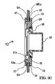
図1は、殺菌液移送ポートのアルファおよびベータ組立体10および100の等角図であり、図5Iおよび5Jと関連させて理解することができる。図5Iは、充填モードのSLTPの立面図であり、図5Jは、充填モードのSLTPの詳細図である。
FIG. 1 is an isometric view of the alpha and
図5Iは、分離壁201で第1の側205が第2の側204から分離される関連環境におけるSLTPシステムを示す。第1の側205は、プロダクトタンク202を有するプロダクト室とすることができる。第2の側204は、充填機器209を有する充填室とすることができる。第1の側205は、比較的「汚れた」側とすることができ、クラス10,000環境と分類することができる。第2の側204は、比較的「清浄な」側とすることができ、クラス100環境と分類することができる。液体を、「汚れた」側のプロダクトタンク202から、「清浄な」側の充填機器209へ、液体を汚染することなく移送するのが望ましいことが多い。SLTPシステムは、かかる液体の移送を助けることができる。
FIG. 5I shows the SLTP system in an associated environment where the first side 205 is separated from the
図1、2Aおよび5Jに示すとおり、アルファ組立体10は、分離窓201aの移送ポート201bをまたぐ。アルファ組立体10は、図5Iに示すとおり、充填室204(クラス100環境)と主に関連付けられるが、アルファ組立体10は、後方部がクラス10,000環境に露出されている比較的「汚れた」環境であるプロダクト室205に延在している。しかしながら、ベータ組立体100は、様々な環境において、プロダクト室205、すなわち「汚れた」側にのみ関連付けられており、アルファ組立体10の後方部分にドッキングされている。
As shown in FIGS. 1, 2A and 5J, the
アルファ組立体10は、ベータ組立体100とドッキングするように構成されており、これは、図5A〜図5Fに段階的に示されており、これについて以下に説明する。アルファ10およびベータ組立体100をドッキングすると、プロダクトは、汚染物質を分解することなく、プロダクト室205から充填室204(図5I)まで移送することができる。充填モードにおいて、ベータ組立体100は、図5Aに示すとおり、アルファ組立体10とインラインで装着されている。図5Fおよび5Gを見ると、アルファおよびベータ組立体10および100を一緒にドッキングして、アルファドア16を開けると、剛性プロダクト管109は、充填室204へ延在しており、殺菌可撓性充填ホース208に取り付ける準備ができている。殺菌可撓性充填ホース208は、プロダクト(例えば、血清およびワクチン)を、分配のための商用規模の容器に送達することができる。
The
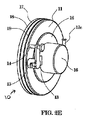
図2Aは、アルファ組立体10の分解図である。アルファ組立体10は、第1のフランジガスケット18、第2のフランジガスケット18、フランジナット17、アルファフランジ11およびアルファドア16を有する。フランジガスケット18は、アルファフランジ11と分離窓201aとの間のシールである。シールは、分離窓201aの第1の側から分離窓201aの第2の側まで、または分離窓201aの第2の側から分離窓201aの第1の側までの漏れを防ぐ。第2のフランジガスケット18は、分離窓201aの第1のフランジガスケット18とは反対の側に位置している。第2のフランジガスケット18はまた、分離窓201aのプロダクト室205側から、分離窓201aの充填室204側への漏れを防ぐ役割も果たす(図5Iに図示)。分離窓のプロダクト室側に位置するフランジナット17は、アルファフランジ11および2つのフランジガスケット18を、分離窓201aに固定する。アルファドア16は、アルファフランジ11に配置されている。
FIG. 2A is an exploded view of the
図2Bは、アルファ組立体10の立面図である。アルファ組立体10は、アルファフランジ11とアルファドア16を含む。アルファドア16は、分離壁の片側に開いており、図5Iに示す分離壁の充填室側とすることができる。様々な実施形態において、アルファドア16は、充填操作が進行中でなければ、通常、閉じている。このように、アルファドア16は、図5Iに示すように、プロダクトタンク202の殺菌を含み得る殺菌中も閉じたままである。殺菌は、通常、充填操作の開始前に行われる。
FIG. 2B is an elevational view of the
図2Bにはまた、アルファドア16に取り付けられたラッチ13も示されている。ラッチハンドル14が、ラッチ13と係合する。ラッチハンドル14が上部位置にあるときは、一実施形態において、アルファドア16のように、ラッチ13はロックされる。アルファドア16は、一実施形態において、図5Iより、充填室204とすることのできる分離壁の清浄な側の不注意な汚染を避けるために、閉じているときは常に、ロック位置にある。
Also shown in FIG. 2B is a
メカニカルラッチインターロック15は、SLTPの不適切または望まない操作を防ぐことができる。例えば、かかる不適切な操作としては、ベータ組立体100をアルファ組立体10とドックする前にアルファドア16を開く、アルファドア16が開いているときに、アルファ組立体10からベータ組立体100を取り去る、およびアルファドア16が開いているときに、アルファドア16のラッチハンドル14を回すことがある。ラッチインターロック15は、アルファドア16が偶発的に開くのを防ぐことができる。ベータ組立体100が、アルファ組立体10とドックされているとき、ベータ組立体100によるラッチインターロック15の自動係合解除により、アルファドア16を開くことができる。アルファドア16は、一実施形態において、ラッチハンドル14を、反時計回りに180°回転することにより安全に開くことができる。ただし、他の角度の回転も想定される。
The
図2Bにはまた、ヒンジ12a、ヒンジピボットブロック12bおよびヒンジピン12cで構成されたヒンジ組立体12も示す。ヒンジ12aは、アルファドア16に取り付けられている。ヒンジ組立体12は、平面で、アルファドア16とアルファヒンジ11との間にピボット結合を与える。ヒンジ12aによって、アルファドア16をヒンジピン12c周囲でピボットまたは回転することができ、アルファドア16を開閉することができる。ヒンジピボットブロック12bは、サポートガイドの機能を果たして、回転またはピボット中、および開いた位置にある間、アルファドア16を水平配置に維持する。
FIG. 2B also shows a
図2Cは、図2Bのアルファ組立体10の断面図である。アルファ組立体10は、分離壁の第2の側からの分離壁の第1の側の、例えば、図5Iに示すように、充填室204からのプロダクト室205の分離を維持するためのものである。かかる分離は、SLTPが殺菌モードか充填モードかに関わらず維持される。アルファフランジ11の据え付けは比較的永久的であるが、ベータフランジ101は頻回に挿入されかつ取り外される。アルファ組立体10の一例の構造を説明していく。
FIG. 2C is a cross-sectional view of the
アルファ組立体10は、フランジ11、アルファドア16、バヨネットレシーバ11a、バヨネットレシーバチャネル11b、フランジナット17、アルファシール19、プロダクト室側のガスケット18および充填室側のガスケット18で構成されている。アルファシール19は、アルファドア16の内側を囲んでおり、密閉の際に、ドア16をフランジ11にシールする。
The
典型的に、分離窓201aは、分離壁201の開口部に据え付けられており、アルファフランジ11は、分離壁201の移送ポート201bに据え付けられている。アルファフランジ11は、分離壁201において移送ポート201b(図2A参照)に挿入されている。フランジ11の挿入前に、充填室側のガスケット18を、フランジ11周囲に導入する。分離窓201aを用いて、プロダクトおよび/または充填室204および205における活動をモニターする。アルファフランジ11を移送ポート201bに据え付けた後、プロダクト室204側のガスケット18を、フランジ11周囲に配置し、フランジナット17を、場合によっては、分離窓201aまたは分離壁201に対して締結する。
Typically, the
図2Dは、後方から見た、アルファ組立体10の立面図である。アルファバヨネットレシーバ11aはまた、第3のコネクタセット11aとも呼ぶこともでき、ベータ組立体100を、アルファ組立体10とドックするとき、ベータフランジバヨネット101aと噛合係合するように構成されている。以下に詳細に後述するとおり、ベータフランジバヨネット101aは、第1のコネクタセットと呼ぶことができる。初期ドッキング後、ハンドル104a(図3C参照)を用いて、ベータフランジバヨネット101aを、反時計回りに回転させて、アルファバヨネットレシーバチャネル11b下でベータフランジバヨネット101aを解放可能にロックする。第4のコネクタセット16aと呼ぶことのできるアルファドアバヨネット16aはまた、ベータカバーバヨネットレシーバ102bと噛合係合するように構成され、ベータカバーバヨネットレシーバ102bは、第2のコネクタセット102bと呼ぶことができる。ハンドル104aを用いて、ドックされたベータアセンブリ100を反時計回りにさらに回転させて、ベータフランジの回転によって、ベータカバーバヨネットレシーバチャネル102c下でアルファドアバヨネット16aを解放可能にロックする。
FIG. 2D is an elevation view of the
図2Eは、アルファドア16が閉じたアルファ組立体10の等角図である。前述したとおり、ラッチハンドル14は、ラッチ13と係合している。ラッチハンドル14を、上部位置にすると、ラッチ13、それによってアルファドア16がロックされる。図2Fは、アルファドアが開いたアルファ組立体の等角図である。アルファドア16を開くには、ラッチハンドル14を反時計回りに180°回転させる。
FIG. 2E is an isometric view of the
図3Aは、前方からのベータ組立体100の等角図である。ベータ組立体は、プロダクトの殺菌移送のために、アルファ組立体を分離壁の第1の側から接続するように構成されている。ベータ組立体は、通常、内部空間を画定する第1の側101と第2の側102を有する筺体を有しており、第1の側101はベータフランジ101、第2の側102はベータカバー102とすることができる。第1のコネクタセット101aは、第1の側101に画定され、第2のコネクタセット102bは第2の側102に画定される。ベータフランジ101は、ベータカバー102に解放可能にロックされる。少なくとも1つの実施形態において、筺体の第1の側101のフランジバヨネット101aは、ドッキングカバーのバヨネットレシーバ111bと係合するように構成されている。ベータ組立体100はまた、ベータシール103も有する。
FIG. 3A is an isometric view of the
ベータカバー102は、ベータカバーエンドキャップ102dを有しており、剛性プロダクト管109と剛性ドレン管107のための密閉内部空間100a(図3Bに図示)を提供する。プロダクト管109は、内部空間100aから筺体の外側までの通路を画定している。カバーエンドキャップ102dにより形成された密閉内部空間100aは、殺菌モードで用いられる。サニタリー継手クランプ110は、殺菌処理中に用い、充填処理中にプロダクトを移送するために、可撓性プロダクトホース203を剛性プロダクト管109に接続する。ベータカバー102は、ベータカバーバヨネット102aを、ベータフランジ100のバヨネットカバーレシーバ101bと位置合わせしてから、ベータカバーバヨネットレシーバチャネル101c下でベータカバーバヨネット102aを回転することにより、ベータフランジに解放可能にロックされる。
The
ベータフランジ101は、少なくとも1つのハンドル、ある実施形態においては、2つのハンドル、ブラケット104aおよび104b、サニタリー継手クランプ110およびフランジバヨネット101aを含む。フランジバヨネット101aとすることのできる第1のコネクタセット101aは、ベータ組立体100のアルファ組立体10とのドッキング中、アルファバヨネットレシーバ11aと位置合わせされる。カバーシール103は、ベータカバー102がベータフランジ101に接続されると、ベータカバーエンドキャップ102dをベータフランジ101にシールする。ハンドル104aを用いて、ベータフランジバヨネット101aを反時計回りに回転させ、アルファバヨネットレシーバチャネル11b下でベータフランジバヨネット101aを解放可能にロックする。アルファドアバヨネット16aは、ベータカバーバヨネットレシーバ102bと噛合係合するように構成されている。ベータフランジバヨネット101aの反時計回転はまた、ベータフランジバヨネットレシーバチャネル102c下でアルファドアバヨネット16aも解放可能にロックする。
The
図3Bは、前方からのベータ組立体100の分解等角図である。この図面では、ベータフランジの内部空間100aを明瞭に見ることができる。サニタリー継手クランプ110、サニタリー継手キャップ106およびサニタリー継手シール105の組み合わせを含む第1のホース接続装置は、プロダクトタンク202からの可撓性プロダクトホース203と剛性プロダクト管109との間を、工具を用いずに、接続する。第2のホース接続装置はサニタリー継手クランプ110、サニタリー継手シール105およびサニタリー継手キャップ106の組み合わせを組み込んで、プロダクト管109と可撓性充填ホース208との間を、工具を用いずに、接続する。剛性ドレン管107は、内部空間100aに示されており、サニタリー継手クランプ110、サニタリー継手シール105およびサニタリー継手アダプタ108と組み合わせられる。ベータ組立体100の内部空間100aと、剛性ドレン管107と、可撓性蒸気ドレンホース207との間を接続する。剛性ドレン管107は、殺菌処理中に用いられる。剛性ドレン管107は、内部空間100aから、ベータ組立体00の筺体の外側までの通路を画定する。
FIG. 3B is an exploded isometric view of the
図3Cは、後方からのベータ組立体の立面図である。図3Dは、図3Aのベータ組立体100の断面図である。プロダクトポートおよびドレンポートは、図3Dの後方に示されているとおり、ベータ組立体の貯蔵のためのサニタリー継手アダプタ106でキャップされている。
FIG. 3C is an elevational view of the beta assembly from the rear. FIG. 3D is a cross-sectional view of the
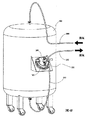
ドッキングカバーは、通常、分離壁の第1の側に位置し、殺菌処理中、ベータ組立体と接続するように構成されている。図4Aは、ドッキングカバー111がプロダクトタンクに位置するプロダクトタンク202の等角図である。ドッキングカバー111は、プロダクト室205内の壁、ベンチまたはその他便利な場所に配置されていてよい。タンク202は、ホイールと共に示されており、タンク202は、プロダクト室205内で可動、または全く異なるプロダクト室に対して可動であることが示されている。SLTPは、複数のプロダクト室202およびベータ組立体100、さらに1つのみのアルファ組立体10を含むのが一般的である。ベータ組立体100はまた、可動プロダクト室205に配置することもできる。可撓性プロダクトホース203は、殺菌中、蒸気供給ホースとして、そして、充填中、プロダクトをベータ組立体に移送するために用いられる。各ホース203、207および208は、ベータ組立体100に接続するとき、サニタリー継手アダプタ108に取り付けられる。
The docking cover is typically located on the first side of the separation wall and is configured to connect with the beta assembly during the sterilization process. FIG. 4A is an isometric view of
図4Bは、ドッキングカバー111とドッキングされるように位置合わせされたベータ組立体100の等角図である。ドッキングカバー111は、通常、筺体100の一部を収容する開口部を画定している。ドッキングカバー111は、装着プレート200に取り付けられており、これは、プロダクトタンク202の外側に取り付けられている。ベータ組立体100、ベータカバー102および装着プレート200は、タンク202の内側には全く接続されていない。ドッキングカバー111は、ベータ組立体100の第1のコネクタセット101aまたはベータフランジバヨネット101aと係合する、第5のコネクタセット111bと呼ぶことのできるバヨネットレシーバ111bを有している。当業者であれば想到されるであろうように、第1のコネクタセット101aおよび第5のコネクタセット111bは、様々な異なるやり方で噛合う様々な噛合コンポーネントとすることができる。ただし、本明細書に開示された実施において記載されたコネクタセットは、通常、バヨネット接続である。少なくとも一実施形態において、ベータ組立体100は、ドッキングカバーに、何らかの工具を用いることなく、装着される。
FIG. 4B is an isometric view of the
図4Cに示すとおり、ベータカバーエンドキャップ102dは、装着プレート開口部200aと位置合わせされたドッキングカバー開口部111aに挿入されている。 As shown in FIG. 4C, the beta cover end cap 102d is inserted into the docking cover opening 111a aligned with the mounting plate opening 200a.
バヨネットレシーバ111bへのバヨネット101aの挿入後、ベータ組立体は、図4Dに示すとおり、ハンドル組立体104を用いて、ベータ組立体を反時計回転させることにより、ドッキングカバーに装着されており、それにより、ドッキングカバーバヨネットレシーバチャネル111cにおいて、ベータフランジバヨネット101aが回転する。サニタリー継手アダプタ108も示されている。
After insertion of the
図4Eは、可撓性プロダクトホース203および蒸気ドレンホース207を備えたベータ組立体の等角図である。プロダクトホース203は、ベータ組立体100のプロダクト管109に接続されている。同様に、ドレンホース207は、ドレン管107に接続されている。
FIG. 4E is an isometric view of the beta assembly with
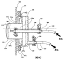
図4Fおよび4Gは、蒸気殺菌モードの、プロダクトタンク202、およびドッキングカバー111にドックされたベータ組立体100の等角図である。蒸気源からの蒸気は、プロダクトタンク202の上部へ導入され、可撓性蒸気供給ホース206を通過する。蒸気は、タンク202の下部から出て、可撓性プロダクトホース203を通って、剛性プロダクト管109を介して、ベータ組立体100へ移る。蒸気は、ベータ組立体100の内部100aを通って、剛性ドレン管107を出て、可撓性蒸気ドレンホース207を通って、廃棄のために凝縮タンク(図示せず)へ移る。
4F and 4G are isometric views of the
図4Gに、ベータ組立体内部100aおよびベータ組立体100へのホース接続の詳細を示す。図面から見えるとおり、シール103は、ベータカバーの一部とベータフランジの一部との間に位置決めされ、ベータ組立体が、ドッキングカバーと噛合わされるとき、ドッキングカバーは、シールと接触している。シールと接触させることにより、ドッキングカバーは、殺菌処理中、シールをサポートする。ベータカバー、ベータフランジおよびドッキングカバーの組み合わせは、シールの全ての側のシールと接触する。カバーなしだと、殺菌処理中の蒸気圧によって、シールが、その場所から外れて、漏れる可能性があり、殺菌処理が失敗するであろう。ドッキングカバーありだと、シール103がさらにサポートされ、殺菌処理が成功する可能性が高い。
FIG. 4G shows details of the
ベータ組立体100は、殺菌処理の不可欠な部分である。殺菌処理は、空の(i)プロダクトタンク202、(ii)可撓性プロダクトホース203、(iii)可撓性蒸気供給ホース206、(iv)可撓性蒸気ドレンホース207、(v)ベータ組立体100および(vi)蒸気源の内部表面を含む。ベータ組立体100は、ベータ組立体内部100aを含む。内部100aは、(i)剛性プロダクト管109、(ii)ベータフランジ101、(iii)ベータカバー102および(iv)剛性ドレン管の出口107aを含む。
The
長期間、高温および高圧に曝すことによって、殺菌システムの全内部表面が確実に殺菌される。アルファ組立体10のアルファドア16は、殺菌がなされている間、閉じられ、シールされている。高温および高圧の飽和蒸気は、殺菌システムに循環される。飽和蒸気は、約36.3psiの作動圧力で(プロダクトの種類に応じて異なる)、システムに注入される。飽和蒸気温度は、システムに入るとき、約150℃である(プロダクトの種類に応じて異なる)。殺菌の必要なレベルは、剛性ドレン管107での蒸気温度を連続的にモニタリングして、ドレン管107の蒸気温度が、確実に、150℃または約150℃(プロダクトの種類に応じて異なる)のままとなるようにすることにより、維持される。システムが殺菌された後、凝縮物は、システムに熱い乾燥空気を注入することによりシステムから除去される。
Exposure to high temperatures and pressures for extended periods ensures that all internal surfaces of the sterilization system are sterilized. The
殺菌処理完了の際、ベータ組立体100は、ドッキングカバー111からアンドックされ、アルファ組立体10とドックされる。殺菌処理中、可撓性プロダクトホース203は、ベータ組立体100の後方で、剛性プロダクト管109に接続された。殺菌を維持するには、可撓性プロダクトホース203は接続したままにしなければならない。可撓性蒸気ドレンホース207およびサニタリー継手アダプタ108は、剛性ドレン管107から取り外し、サニタリー継手キャップ106と交換されなければならない。
Upon completion of the sterilization process, the
図5Aは、ベータ組立体がアルファ組立体とドッキングされるように位置合わせされた、ベータおよびアルファ組立体100および10の等角図である。第1の側100の第1のコネクタセット101aおよび第2の側102の第2のコネクタセット102b(例えば、図3Aで見られる)、第1のコネクタセット101aは、アルファ組立体10の第3のコネクタ11aセットと噛合わされるように構成されており、第2のコネクタセット102bは、アルファ組立体10の第4のコネクタセット16aと噛合わされるように構成されている。第1のコネクタセット101aはまた、図4B〜4Eについて上述したとおり、プロダクトタンクの第5のコネクタセットと噛合わされるように構成することもできる。本明細書に図示および記載したものを含む様々な実施形態において、第1、第2、第3、第4および第5(図4Aで説明)は、バヨネット接続である。図5Bは、ベータフランジバヨネット101aがアルファバヨネットレシーバ11aに受けられた、ベータ組立体の等角図である。当業者であれば、様々なその他の種類の接続を用いることができ、それでも、本明細書に開示された技術の範囲内にあることが分かるであろう。
FIG. 5A is an isometric view of the beta and
図5Cに示すとおり、ベータフランジバヨネット101aは、アルファバヨネットレシーバチャネル11b下で反時計回転する。第1の101aおよび第3の11bコネクタセットは、互いに対して回転する際に係合および係合解除されるように構成することができる。同様に、第2および第4のコネクタセットは、互いに対して回転する際に係合および係合解除されるように構成することができる。ただし、第1および第3のコネクタセットを係合および係合解除する他の手段を用いることができる。
As shown in FIG. 5C, the
図5Dは、アルファドア16がラッチされた、アルファおよびベータ組立体10および100の等角図である。
FIG. 5D is an isometric view of the alpha and
図5Eは、アルファドア16がラッチされていないアルファおよびベータ組立体10および100の等角図である。
FIG. 5E is an isometric view of the alpha and
図5Fは、アルファドア16が開いていて、それにより、可撓性充填ホース208に取り付けるのに、サニタリー継手アダプタ108に接近可能な、アルファおよびベータ組立体の等角図である。
FIG. 5F is an isometric view of the alpha and beta assembly with the
図5Gは、1つの剛性プロダクト管109を有するアルファおよびベータ組立体10および100の等角図である。図5Hは、2つの剛性プロダクト管109を有するアルファおよびベータ組立体10および100の等角図である。特定の場合においては、2つの物質を、別個のプロダクトタンクから、各プロダクト管109へ個別に計量して、2成分薬剤へと組み合わせることがある。このようにして、任意の数の別個のプロダクト管を用いて、様々な物質を一緒に混合してよい。図5Gおよび5Hにおいて、ベータ組立体100が、アルファ組立体10と係合しているとき、ベータカバー102の後方は、アルファドア16に捉えられる。可撓性充填ホース208は、充填室204に延在している。
FIG. 5G is an isometric view of alpha and
図5Iは、充填モードのSLTPの立面図である。 FIG. 5I is an elevation view of SLTP in fill mode.
図5Jは、充填モードにあるSLTPの詳細図である。プロダクトの充填室204への移送は、プロタクトタンク202のポンピング、重力送りまたは加圧により行ってよい。典型的に、プロダクトは、加圧下で貯蔵される。
FIG. 5J is a detailed view of SLTP in fill mode. The product may be transferred to the filling
図5A〜5Jに示すとおり、アルファ組立体10およびベータ組立体100は、殺菌液体プロダクトの汚染されない移送プロセスを実施する。プロダクト室205は、アルファ組立体10により、充填室204から常に分離されている。アルファ組立体10は、ベータ組立体100をドッキングするための境界面を有している。アルファ組立体10は、アルファドア16が、アルファ組立体10にベータ組立体100がドックされないと開くことができないように構成されている。これによって、プロダクト室205が充填室204を確実に汚染しないようになる。
As shown in FIGS. 5A-5J,
殺菌液体プロダクトを、プロダクトタンク202から充填室204まで移送するために、(i)可撓性蒸気供給ホース206をプロダクトタンク202から遮断し、(ii)可撓性蒸気ドレンホース207をベータ組立体100のサニタリー継手アダプタ108から遮断し、アダプタをベータ組立体から取り外し、アダプタ108をプラグに交換し、(iii)可撓性プロダクトホース203を取り付けたベータ組立体100をドッキングカバー111からアンドックし、アルファ組立体10とドックする。そして、プロダクトタンク202をプロダクトで充填する。
In order to transfer the sterilizing liquid product from the
ベータ組立体100を回転させ、それをアルファ組立体10に対してドッキングすると、4つの事象が同時に起こる。第1に、ドッキング中、ベータフランジ101は、アルファフランジ11に強固に取り付けられる。第2に、ドッキングによって、ベータカバー102が、ベータフランジから取り外される。第3に、外側表面がプロダクト室205に露出されたベータカバー102が、アルファドア16に取り付けられる。全外側表面は、アルファシール19によりアルファドア16内側にシールされる。最後に、ドッキングプロセスによって、アルファ組立体10のインターロック機構の係合が解除され、これによって、アルファドア16を安全に開くことができる。いったん開くと、ベータカバー102は、ベータフランジ101から分離され、それにより、殺菌液剛性プロダクト管109、殺菌サニタリー継手シール105、殺菌サニタリー継手アダプタ108および殺菌サニタリー継手クランプ110が、清浄な充填室204に対して露出される。可撓性充填ホース208の取り付けによって、プロダクト室205から、汚染することなく、充填室204、続いて充填機器209への殺菌液の移送が可能となる。
When the
Claims (10)
(1)前記分離壁の前記第1の側と前記第2の側との間の前記分離壁にある前記移送ポートをまたぐように構成されたアルファ組立体(10)と、
(2)ベータ組立体(100)であって、
第1の側(101)および第2の側(102)を有し、内部空間(100a)を画定している筺体と、
前記内部空間から、前記筺体の外側までの通路を画定しているプロダクト管(109)と、
前記内部空間から、前記筺体の外側までの通路を画定しているドレン管(107)と、
前記第1の側の第1のバヨネット接続(101a)および前記第2の側の第2のバヨネット接続(102b)であって、殺菌液プロダクトの移送の間、前記アルファ組立体(10)の第3のバヨネット接続(11a)と噛合うように構成された第1のバヨネット接続(101a)、および、殺菌液プロダクト移送の間、前記アルファ組立体の第4のバヨネット接続(16a)と噛合うように構成された第2のバヨネット接続(102b)と
を含むベータ組立体と、
(3)前記分離壁の前記第1の側のドッキングカバー(111)と
を含み、
前記第1のバヨネット接続(101a)が、殺菌プロセスの間、該ドッキングカバー(111)の第5のバヨネット接続(111b)と噛合うようにさらに構成されており、
蒸気が前記プロダクト管(109)を介して前記組立体に導入され、前記組立体の内部空間(100a)を通って、廃棄のために前記ドレン管(107)から出る、組立体。 An assembly for a sterilizing liquid transfer port system configured to transfer a sterilizing liquid product via a transfer port (201b) of a separation wall (201) separating a first side and a second side. And
(1) an alpha assembly (10) configured to straddle the transfer port in the separation wall between the first side and the second side of the separation wall;
(2) a beta assembly (100) comprising:
A housing having a first side (101) and a second side (102) and defining an interior space (100a);
A product tube (109) defining a passage from the interior space to the outside of the housing;
A drain pipe (107) defining a passage from the internal space to the outside of the housing;
A first bayonet connection of said first side (101a) and a second bayonet connection of the second side (102b), during transport of the sterilizing liquid product, the said alpha assembly (10) A first bayonet connection (101a) configured to mate with three bayonet connections (11a) and to engage the fourth bayonet connection (16a) of the alpha assembly during sterilization product transfer. A second bayonet connection (102b) configured in
A beta assembly comprising:
(3) looking contains the said separating wall first side of the docking cover (111),
Before SL first bayonet connection (101a) is, during the sterilization process, which is further configured to mate with the fifth bayonet connection of the docking cover (111) (111b),
An assembly wherein steam is introduced into the assembly via the product tube (109) and exits the drain tube (107) for disposal through the interior space (100a) of the assembly.
前記内部空間(100a)から、前記筺体の外側までの通路を画定しているプロダクト管(109)と、
前記内部空間(100a)から前記筺体の外側までの通路を画定しているドレン管(107)と、
前記ベータカバー(102)の一部と前記ベータフランジの一部との間に位置決めされたシール(103)と、
バヨネットレシーバ(111b)を有するドッキングカバー(111)と、
前記ドッキングカバー(111)の前記バヨネットレシーバ(111b)を係合するように構成された前記ベータフランジ(101)にあるフランジバヨネット(101a)と
を含む殺菌組立体であって、
前記殺菌組立体は、殺菌液移送ポートシステムにおける使用のためのものであり、
前記殺菌液移送ポートシステムは殺菌液プロダクトの殺菌液移送のために構成されており、
(i)前記筐体およびフランジバヨネット(101a)を含むベータ組立体であって、前記ベータ組立体(100)は、殺菌液プロダクト移送の間のアルファ組立体との接続のために構成され、前記アルファ組立体は、分離壁の第1の側と第2の側の間の前記分離壁の移送ポートをまたぐものである、ベータ組立体と、
(ii)殺菌プロセスの間の前記ベータ組立体への接続のために構成されている前記分離壁の前記第1の側にあるドッキングカバー(111)と
を含み、
蒸気が前記プロダクト管(109)を介して前記ベータ組立体に導入され、前記ベータ組立体の内部空間(100a)を通って、廃棄のために前記ドレン管(107)から出て、
前記ドッキングカバー(111)は、前記ベータ組立体(100)が前記ドッキングカバー(111)と噛合わされると前記シール(103)と接触する、殺菌組立体。 A housing having a beta flange (101) and a beta cover (102) and defining an interior space (101a), the beta flange (101) being releasably locked to the beta cover (102); A housing that provides the internal space (100a) when locked to the cover;
A product tube (109) defining a passage from the internal space (100a) to the outside of the housing;
A drain pipe (107) defining a passage from the internal space (100a) to the outside of the housing ;
A seal (103) positioned between a portion of the beta cover (102) and a portion of the beta flange;
A docking cover (111) having a bayonet receiver (111b);
A sterilization assembly comprising a flange bayonet (101a) on the beta flange (101) configured to engage the bayonet receiver (111b) of the docking cover (111) ;
The sterilization assembly is for use in a sterilant transfer port system;
The sterilizing liquid transfer port system is configured for sterilizing liquid transfer of the sterilizing liquid product,
(I) a beta assembly including the housing and a flange bayonet (101a), wherein the beta assembly (100) is configured for connection with an alpha assembly during sterilizing liquid product transfer ; alpha assembly is to cross the transfer port of the separating wall between the first and second sides of the separation wall, a beta assembly,
(I i) and a said docking cover on the first side of the separation wall, which is configured for connection to the beta assembly during the sterilization process (111),
Steam is introduced into the beta assembly via the product tube (109), passes through the interior space (100a) of the beta assembly, exits the drain tube (107) for disposal ,
The docking cover (111) is a sterilization assembly that contacts the seal (103) when the beta assembly (100) is engaged with the docking cover (111) .
ベータカバー(102)と、
前記カバー(102)に解放可能にロックされ、前記カバー(102)にロックされると前記内部空間(100a)を提供するベータフランジ(101)と
をさらに含む、請求項1に記載の組立体。 The housing is
A beta cover (102);
The assembly of claim 1, further comprising a beta flange (101) releasably locked to the cover (102) and providing the interior space (100a) when locked to the cover (102).
Applications Claiming Priority (3)
| Application Number | Priority Date | Filing Date | Title |
|---|---|---|---|
| US12/245,603 | 2008-10-03 | ||
| US12/245,603 US20100084045A1 (en) | 2008-10-03 | 2008-10-03 | Sterile liquid transfer port |
| PCT/US2009/059532 WO2010040126A2 (en) | 2008-10-03 | 2009-10-05 | Sterile liquid transfer port |
Publications (3)
| Publication Number | Publication Date |
|---|---|
| JP2012504475A JP2012504475A (en) | 2012-02-23 |
| JP2012504475A5 JP2012504475A5 (en) | 2012-11-22 |
| JP5753088B2 true JP5753088B2 (en) | 2015-07-22 |
Family
ID=41404106
Family Applications (1)
| Application Number | Title | Priority Date | Filing Date |
|---|---|---|---|
| JP2011530289A Active JP5753088B2 (en) | 2008-10-03 | 2009-10-05 | Disinfectant transfer port |
Country Status (4)
| Country | Link |
|---|---|
| US (2) | US20100084045A1 (en) |
| EP (2) | EP2735317B1 (en) |
| JP (1) | JP5753088B2 (en) |
| WO (1) | WO2010040126A2 (en) |
Families Citing this family (6)
| Publication number | Priority date | Publication date | Assignee | Title |
|---|---|---|---|---|
| US20100084045A1 (en) | 2008-10-03 | 2010-04-08 | Adams Richard H | Sterile liquid transfer port |
| CL2010000644A1 (en) * | 2010-06-18 | 2011-01-14 | Andesocean S A | Sterilization equipment used in the loading of containers for the transport of products in an aseptic way, comprising a portable boiler, pre-washing systems using chemicals, circulation water and hot water, a pump for washing, steam for sterilizing and hoses flexible; and washing method. |
| FR3016794B1 (en) * | 2014-01-24 | 2018-03-02 | Pierre Fabre Dermo-Cosmetique | DEVICE AND METHOD FOR TRANSFERRING A STERILE PRODUCT BETWEEN TWO CONTAINERS |
| GB2542123A (en) * | 2015-09-08 | 2017-03-15 | Chargepoint Tech Ltd | Transfer device |
| BE1023860B1 (en) * | 2016-02-18 | 2017-08-22 | Aseptic Technologies S.A. | Connection system |
| DE102020124826A1 (en) | 2020-09-23 | 2022-03-24 | Syntegon Technology Gmbh | Beta component of a transfer system for a sterile isolation area, sterile isolation area, aseptic filling system and a method for operating such a filling system |
Family Cites Families (11)
| Publication number | Priority date | Publication date | Assignee | Title |
|---|---|---|---|---|
| US4347877A (en) * | 1980-04-21 | 1982-09-07 | Jakob Hoiss | Apparatus for aseptically discharging flowable substances |
| GB2237816A (en) | 1989-11-09 | 1991-05-15 | Cambridge Isolation Tech | Isolator transfer containers |
| GB9325667D0 (en) | 1993-12-15 | 1994-02-16 | Total Process Containment Ltd | Aseptic liquid barrier transfer coupling |
| US5460439A (en) * | 1994-01-07 | 1995-10-24 | Delaware Capital Formation, Inc. | Sealed transfer system |
| US5523519A (en) * | 1994-07-14 | 1996-06-04 | Delaware Capital Formation, Inc. | System for facilitating safe transfer of hazardous material |
| US5662581A (en) * | 1995-01-05 | 1997-09-02 | Delaware Capital Formation, Inc. | Easily sterilizable glove system |
| FR2735201B1 (en) * | 1995-06-08 | 1997-08-29 | Calhene | LID TO BE PLACED ON A DOOR OF A CONTAINER TO BE STERILIZED |
| US5892200A (en) | 1996-09-19 | 1999-04-06 | The Boc Group, Inc. | Transfer port system |
| US7044347B1 (en) * | 2003-03-06 | 2006-05-16 | Fabio Pedrini | Interlock arrangement for an extendible and retractable stabilizer for use in a bicycle carrier |
| US7690406B2 (en) | 2005-10-05 | 2010-04-06 | Delaware Capital Formation, Inc. | Hazardous waste transfer port system and storage container |
| US20100084045A1 (en) | 2008-10-03 | 2010-04-08 | Adams Richard H | Sterile liquid transfer port |
-
2008
- 2008-10-03 US US12/245,603 patent/US20100084045A1/en not_active Abandoned
-
2009
- 2009-10-05 JP JP2011530289A patent/JP5753088B2/en active Active
- 2009-10-05 US US13/122,222 patent/US9198992B2/en active Active
- 2009-10-05 EP EP14155832.0A patent/EP2735317B1/en active Active
- 2009-10-05 WO PCT/US2009/059532 patent/WO2010040126A2/en active Application Filing
- 2009-10-05 EP EP09736351.9A patent/EP2379120B1/en active Active
Also Published As
| Publication number | Publication date |
|---|---|
| US9198992B2 (en) | 2015-12-01 |
| WO2010040126A2 (en) | 2010-04-08 |
| EP2735317B1 (en) | 2015-12-30 |
| US20110256021A1 (en) | 2011-10-20 |
| JP2012504475A (en) | 2012-02-23 |
| EP2735317A1 (en) | 2014-05-28 |
| US20100084045A1 (en) | 2010-04-08 |
| EP2379120A2 (en) | 2011-10-26 |
| WO2010040126A3 (en) | 2010-09-10 |
| EP2379120B1 (en) | 2014-04-23 |
Similar Documents
| Publication | Publication Date | Title |
|---|---|---|
| JP5753088B2 (en) | Disinfectant transfer port | |
| US11666876B2 (en) | Compounder apparatus | |
| US20210008540A1 (en) | Method for protecting and unprotecting the fluid path in a controlled environment enclosure | |
| EP2361032B1 (en) | Quick disconnect fluid connector | |
| JP3246037U (en) | Dry disconnect cartridge and dual lumen needle for automatic drug dispenser | |
| WO2015022396A1 (en) | A container for transporting and storing a liquid | |
| JP2012504475A5 (en) | ||
| WO2014172665A1 (en) | Sealed transfer port with interlocks | |
| EP3265231A1 (en) | Customizable mounting interface for a sealed transfer port | |
| WO1994015864A1 (en) | Process material transfer | |
| KR101376119B1 (en) | Goods delivery device for cleanroom | |
| BR122022013290B1 (en) | FLUID HANDLING ASSEMBLY TO AUTOMATICALLY PERFORM A FLUID HANDLING PROCESS IN AN ASEPTIC ENVIRONMENT | |
| CN117615977A (en) | Protection device for a container, protection arrangement and method for connecting a protection device to a container | |
| Partington | Aseptic processing transfer systems | |
| BR122022013283B1 (en) | METHOD TO AUTOMATICALLY PERFORM A FLUID HANDLING PROCESS IN A CONTROLLED ENVIRONMENTAL COMPARTMENT | |
| BE1023860A1 (en) | Connection system |
Legal Events
| Date | Code | Title | Description |
|---|---|---|---|
| A521 | Request for written amendment filed |
Free format text: JAPANESE INTERMEDIATE CODE: A523 Effective date: 20121001 |
|
| A621 | Written request for application examination |
Free format text: JAPANESE INTERMEDIATE CODE: A621 Effective date: 20121001 |
|
| A977 | Report on retrieval |
Free format text: JAPANESE INTERMEDIATE CODE: A971007 Effective date: 20130718 |
|
| A131 | Notification of reasons for refusal |
Free format text: JAPANESE INTERMEDIATE CODE: A131 Effective date: 20130730 |
|
| A977 | Report on retrieval |
Free format text: JAPANESE INTERMEDIATE CODE: A971007 Effective date: 20130912 |
|
| A601 | Written request for extension of time |
Free format text: JAPANESE INTERMEDIATE CODE: A601 Effective date: 20131029 |
|
| A602 | Written permission of extension of time |
Free format text: JAPANESE INTERMEDIATE CODE: A602 Effective date: 20131106 |
|
| A521 | Request for written amendment filed |
Free format text: JAPANESE INTERMEDIATE CODE: A523 Effective date: 20131202 |
|
| A131 | Notification of reasons for refusal |
Free format text: JAPANESE INTERMEDIATE CODE: A131 Effective date: 20140829 |
|
| A521 | Request for written amendment filed |
Free format text: JAPANESE INTERMEDIATE CODE: A523 Effective date: 20141201 |
|
| TRDD | Decision of grant or rejection written | ||
| A01 | Written decision to grant a patent or to grant a registration (utility model) |
Free format text: JAPANESE INTERMEDIATE CODE: A01 Effective date: 20150422 |
|
| A61 | First payment of annual fees (during grant procedure) |
Free format text: JAPANESE INTERMEDIATE CODE: A61 Effective date: 20150521 |
|
| R150 | Certificate of patent or registration of utility model |
Ref document number: 5753088 Country of ref document: JP Free format text: JAPANESE INTERMEDIATE CODE: R150 |
|
| R250 | Receipt of annual fees |
Free format text: JAPANESE INTERMEDIATE CODE: R250 |
|
| R250 | Receipt of annual fees |
Free format text: JAPANESE INTERMEDIATE CODE: R250 |
|
| R250 | Receipt of annual fees |
Free format text: JAPANESE INTERMEDIATE CODE: R250 |
|
| R250 | Receipt of annual fees |
Free format text: JAPANESE INTERMEDIATE CODE: R250 |
|
| R250 | Receipt of annual fees |
Free format text: JAPANESE INTERMEDIATE CODE: R250 |
|
| R250 | Receipt of annual fees |
Free format text: JAPANESE INTERMEDIATE CODE: R250 |