JP5749010B2 - Sensor - Google Patents
Sensor Download PDFInfo
- Publication number
- JP5749010B2 JP5749010B2 JP2010522454A JP2010522454A JP5749010B2 JP 5749010 B2 JP5749010 B2 JP 5749010B2 JP 2010522454 A JP2010522454 A JP 2010522454A JP 2010522454 A JP2010522454 A JP 2010522454A JP 5749010 B2 JP5749010 B2 JP 5749010B2
- Authority
- JP
- Japan
- Prior art keywords
- transducer
- sample
- reagent
- labeling reagent
- analyte
- Prior art date
- Legal status (The legal status is an assumption and is not a legal conclusion. Google has not performed a legal analysis and makes no representation as to the accuracy of the status listed.)
- Expired - Fee Related
Links
Images


Classifications
-
- G—PHYSICS
- G01—MEASURING; TESTING
- G01N—INVESTIGATING OR ANALYSING MATERIALS BY DETERMINING THEIR CHEMICAL OR PHYSICAL PROPERTIES
- G01N33/00—Investigating or analysing materials by specific methods not covered by groups G01N1/00 - G01N31/00
- G01N33/48—Biological material, e.g. blood, urine; Haemocytometers
- G01N33/50—Chemical analysis of biological material, e.g. blood, urine; Testing involving biospecific ligand binding methods; Immunological testing
- G01N33/53—Immunoassay; Biospecific binding assay; Materials therefor
- G01N33/5302—Apparatus specially adapted for immunological test procedures
-
- G—PHYSICS
- G01—MEASURING; TESTING
- G01N—INVESTIGATING OR ANALYSING MATERIALS BY DETERMINING THEIR CHEMICAL OR PHYSICAL PROPERTIES
- G01N21/00—Investigating or analysing materials by the use of optical means, i.e. using sub-millimetre waves, infrared, visible or ultraviolet light
- G01N21/17—Systems in which incident light is modified in accordance with the properties of the material investigated
- G01N21/1702—Systems in which incident light is modified in accordance with the properties of the material investigated with opto-acoustic detection, e.g. for gases or analysing solids
-
- G—PHYSICS
- G01—MEASURING; TESTING
- G01N—INVESTIGATING OR ANALYSING MATERIALS BY DETERMINING THEIR CHEMICAL OR PHYSICAL PROPERTIES
- G01N21/00—Investigating or analysing materials by the use of optical means, i.e. using sub-millimetre waves, infrared, visible or ultraviolet light
- G01N21/17—Systems in which incident light is modified in accordance with the properties of the material investigated
- G01N21/171—Systems in which incident light is modified in accordance with the properties of the material investigated with calorimetric detection, e.g. with thermal lens detection
-
- G—PHYSICS
- G01—MEASURING; TESTING
- G01N—INVESTIGATING OR ANALYSING MATERIALS BY DETERMINING THEIR CHEMICAL OR PHYSICAL PROPERTIES
- G01N33/00—Investigating or analysing materials by specific methods not covered by groups G01N1/00 - G01N31/00
- G01N33/48—Biological material, e.g. blood, urine; Haemocytometers
- G01N33/50—Chemical analysis of biological material, e.g. blood, urine; Testing involving biospecific ligand binding methods; Immunological testing
- G01N33/53—Immunoassay; Biospecific binding assay; Materials therefor
- G01N33/543—Immunoassay; Biospecific binding assay; Materials therefor with an insoluble carrier for immobilising immunochemicals
- G01N33/54366—Apparatus specially adapted for solid-phase testing
- G01N33/54373—Apparatus specially adapted for solid-phase testing involving physiochemical end-point determination, e.g. wave-guides, FETS, gratings
-
- G—PHYSICS
- G01—MEASURING; TESTING
- G01N—INVESTIGATING OR ANALYSING MATERIALS BY DETERMINING THEIR CHEMICAL OR PHYSICAL PROPERTIES
- G01N21/00—Investigating or analysing materials by the use of optical means, i.e. using sub-millimetre waves, infrared, visible or ultraviolet light
- G01N21/17—Systems in which incident light is modified in accordance with the properties of the material investigated
- G01N21/1702—Systems in which incident light is modified in accordance with the properties of the material investigated with opto-acoustic detection, e.g. for gases or analysing solids
- G01N2021/1708—Systems in which incident light is modified in accordance with the properties of the material investigated with opto-acoustic detection, e.g. for gases or analysing solids with piezotransducers
-
- G—PHYSICS
- G01—MEASURING; TESTING
- G01N—INVESTIGATING OR ANALYSING MATERIALS BY DETERMINING THEIR CHEMICAL OR PHYSICAL PROPERTIES
- G01N2201/00—Features of devices classified in G01N21/00
- G01N2201/06—Illumination; Optics
- G01N2201/062—LED's
Description
本発明は、センサに関し、特に、センサ、及びセンサを用いて結合アッセイ(binding assay)を行う方法に関する。 The present invention relates to a sensor, and more particularly, to a sensor and a method for performing a binding assay using the sensor.
免疫アッセイ(immunoassay)のような結合アッセイでは、検体(しばしば蛋白質又はハプテン)と、抗原(検体)の全体又は部分(エピトープ)に具体的に向けられた(抗体のような)結合部(binding moiety)との間の特定の「鍵穴と鍵(lock-and-key)」相互作用が用いられる。検体と抗体との間の結合は、固有であって、関連はあるが非同定的な種(species)との相互作用を最小化し、強固であって、良好な感度を与える。未知の検体を定量化するため、特徴的なマーカー(例えば、蛍光性又は化学ルミネセンス分子)で標識化された(labelled)検体と、同様に標識化された第2の抗体(「レポーター」)のいずれかの一定量が、サンプルと混合される。次に、過剰に存在する標識化種(labelled species)は、最終的に平衡状態に達して検体と結合し、当該平衡状態では、検体の大部分が、少なくとも1つの標識(label)と関連づけ(associate)られている。標識の濃度は一定であるため、検体を定量化するためには、検体(「結合」部分("bound" fraction))と関連づけられた部分は、関連づけられていないもの(「自由」部分("free" fraction))と物理的に分離される必要がある。次に、いずれかの部分が定量化可能であり、「結合」部分は、検体の濃度に正比例し、「自由」部分は、検体の濃度に反比例する。一般に、「結合」部分と「自由」部分との分離は、第2の抗体(「捕捉」抗体)を用いて成され、検体上の異なるエピトープに向けられ、ビード(bead)又は固体表面のような固相に結合される。このビード又は固相は、次に、バルク溶液から物理的に分離することができ、標識が蛍光性分子である場合には、例えば蛍光光度計を用いて測定が行われる。抗体/抗原相互作用に加え、いくつかの異なる形態の結合相互作用が、結合アッセイに利用可能であり、当該結合相互作用には、DNA/DNA相互作用、RNA/RNA相互作用、及びアプタマー相互作用が含まれるが、これらには限定されない。「競合」アッセイのように、このようなアッセイの代替形態が知られており、当該代替形態では、検体が、公知の量の標識化検体と混合され、次に、これら2つが結合部位と競合する。そして、結合標識化検体の程度は、原サンプルの未標識化(unl
abelled)検体の量に反比例する。
In a binding assay, such as an immunoassay, a binding moiety (such as an antibody) that is specifically directed to the analyte (often a protein or hapten) and all or part (epitope) of an antigen (analyte). A specific “lock-and-key” interaction is used. The binding between the analyte and the antibody is unique, minimizes interaction with related but non-identifiable species, is robust, and provides good sensitivity. To quantify unknown analytes, analytes labeled with characteristic markers (eg, fluorescent or chemiluminescent molecules) and a second antibody (“reporter”) similarly labeled A certain amount of either is mixed with the sample. Second, the excess of labeled species eventually reaches equilibrium and binds to the analyte, where a majority of the analyte is associated with at least one label ( associate). Because the concentration of the label is constant, in order to quantify the analyte, the portion associated with the analyte (the “bound” fraction) must be unrelated (the “free” portion (“ free "fraction)) and need to be physically separated. Next, either portion can be quantified, the “binding” portion being directly proportional to the concentration of the analyte and the “free” portion being inversely proportional to the concentration of the analyte. In general, separation of the “binding” and “free” portions is accomplished using a second antibody (“capture” antibody) and directed to a different epitope on the analyte, such as a bead or solid surface. Bound to a solid phase. This bead or solid phase can then be physically separated from the bulk solution, and if the label is a fluorescent molecule, the measurement is performed using, for example, a fluorimeter. In addition to antibody / antigen interactions, several different forms of binding interactions are available for binding assays, including DNA / DNA interactions, RNA / RNA interactions, and aptamer interactions. Is included, but is not limited thereto. Alternative forms of such assays, such as “competition” assays, are known, in which the analyte is mixed with a known amount of labeled analyte and then the two compete with the binding site. To do. And the extent of bound labeled analyte is determined by the unlabeled (unl
abelled) inversely proportional to the amount of specimen.
「結合」標識化部分と「自由」標識化部分とを、分離ステップ及び洗浄ステップを行う必要なく区別する固有の方法が、WO2004/090512に記載されている。この方法において、捕捉抗体を組み入れる固相は、圧電又は焦電フィルム、典型的にはPVDFである。これは、固相分離特性を測定技法と組み合わせる固有の能力を有している。WO2004/090512に記載のように、(炭素又はコロイド金のような適切な着色物質で標識化された)標識化「レポーター」検体は、測定対象の検体の濃度に比例する速度(rate)で捕捉表面と結合し、この結合は、補色(complementary colour)の光で表面を照射することで同時にモニターされる。光エネルギーは、表面の標識により吸収され、非放射減衰(non-radiactive decay)により熱として放出され、PVDFフィルムにより検出される。同時にこのシステムの利点は、バルク溶液中の非結合標識により同様に吸収されたエネルギーが、PVDFフィルムにより検出されずに液体媒体中で失われることであり、こうして「結合」部分と「自由」部分との「分離」に自動的に影響する。十分なサイズのコロイド粒子を用いることには、有意な個数の陽子が粒子により吸収されて、強い信号をもたらし、その結果、良好な感度をもたらすという利点がある。 A unique method for distinguishing between “bound” and “free” labeling moieties without having to perform separation and washing steps is described in WO 2004/090512. In this method, the solid phase incorporating the capture antibody is a piezoelectric or pyroelectric film, typically PVDF. This has the inherent ability to combine solid phase separation properties with measurement techniques. As described in WO 2004/090512, labeled “reporter” analytes (labeled with a suitable colored substance such as carbon or colloidal gold) are captured at a rate proportional to the concentration of the analyte to be measured. It binds to the surface and this bond is monitored simultaneously by illuminating the surface with complementary color light. Light energy is absorbed by the surface label, released as heat by non-radiactive decay, and detected by the PVDF film. At the same time, the advantage of this system is that the energy similarly absorbed by the unbound label in the bulk solution is lost in the liquid medium without being detected by the PVDF film, thus the “bound” and “free” portions It automatically affects “separation”. The use of sufficiently sized colloidal particles has the advantage that a significant number of protons are absorbed by the particles, resulting in a strong signal and consequently good sensitivity.
WO2004/090512に記載のセンサは、標識が捕捉表面に結合するキネティクスをリアルタイムにモニターするのに用いられ、これは、検体の濃度に比例する。この方法は、標識化種の表面への拡散速度と、表面での結合速度とに依存する。これらの速度のいずれかが準最適(sub-optimal)である場合、アッセイの全感度又は反応時間は、制限しても構わない。表面での結合速度は、(例えば大きな炭素又は金粒子が標識として使用される場合、)標識化検体間の立体障害(steric hindrance)のような、多くの要素により制限可能である。加えて、大きな(20〜500nm)粒子の固体表面への接近を妨げる静電斥力が存在することもあるし、又は、粒子が固相に接近するが、粒子上の結合表面が結合が生じるのに不当な方向に向けられる配向効果が存在することもある。これは、多くの抗体で覆われた大きな粒子と共に、これらの抗体の小さな部分のみが検体に結合されて、より起こりやすくなり、この結果、粒子の表面領域の小さな部分だけが、表面へと結合するのに使用される。結合速度のこれら制限要素に加えて、免疫アッセイ試験に用いられる粒子のサイズを制限可能なその他の要素も存在する。例えば、従来の「側方流動(lateral flow)」免疫クロマトグラフィ・ストリップ試験では、コロイド金粒子の最適なサイズは、約40nmである。理由は、より大きな粒子が、そのサイズ及び密度(density)に起因して流動膜(flow membrane)中にトラップされる傾向があるからである。最後に、大きな粒子ほど、拡散速度が低く、そのため、捕捉表面に拡散するのに長時間かかり、その結果、利用可能な信号を制限する可能性がある。 The sensor described in WO 2004/090512 is used to monitor in real time the kinetics that the label binds to the capture surface, which is proportional to the concentration of the analyte. This method depends on the diffusion rate of the labeled species to the surface and the binding rate on the surface. If any of these rates is sub-optimal, the overall sensitivity or reaction time of the assay may be limited. The rate of binding at the surface can be limited by many factors, such as steric hindrance between labeled analytes (eg, when large carbon or gold particles are used as labels). In addition, there may be electrostatic repulsion that prevents large (20-500 nm) particles from approaching the solid surface, or the particles approach the solid phase but the binding surface on the particles causes binding. There may be orientation effects that are directed in an unjustified direction. This is more likely with large particles covered with many antibodies, with only a small portion of these antibodies bound to the analyte, so that only a small portion of the surface area of the particles binds to the surface. Used to do. In addition to these limiting factors of binding rate, there are other factors that can limit the size of particles used in immunoassay tests. For example, in a conventional “lateral flow” immunochromatographic strip test, the optimal size of colloidal gold particles is about 40 nm. The reason is that larger particles tend to be trapped in the flow membrane due to their size and density. Finally, the larger the particles, the lower the diffusion rate, so it takes a longer time to diffuse to the capture surface, which can limit the available signal.
従って、この技術分野には、このようなアッセイの感度の更なる向上へのニーズが依然としてある。 Accordingly, there remains a need in the art for further improving the sensitivity of such assays.
従って、本発明は、サンプル中の検体を検出する方法であって、
エネルギーの変化を電気的信号に変換することが可能な変換器(transducer)に、前記サンプルをさらすステップであって、前記変換器は、前記変換器上に又は前記変換器に近接して少なくとも1つの連結試薬(tethered reagent)を有し、前記少なくとも1つの連結試薬は、前記検体と結合することが可能な結合部位(binding site)を有する、ステップと、
標識化試薬(labelled reagent)を前記サンプル中に導入するステップであって、前記標識化試薬は、前記検体用又は前記連結試薬用の結合部位と、エネルギーを生成するよう、放射源により生成された電磁放射を吸収することが可能な標識とを含む、ステップと、
前記標識化試薬を、第1の期間において、前記検体又は前記連結試薬と結合させるステップであって、前記変換器は、前記標識化試薬が、少なくとも部分的に前記変換器上に定着(settle)されるよう方向付けられている、ステップと、
続いて、第2の期間において、前記標識化試薬を不安定化(unsettle)させるステップと、
前記第1及び第2の期間の間において、前記サンプルに電磁放射を照射するステップと、
前記生成されたエネルギーを電気的信号に変換するステップと、
前記電気的信号を検出するステップと、
を含む方法を提供する。
Accordingly, the present invention is a method for detecting an analyte in a sample,
Subjecting the sample to a transducer capable of converting a change in energy into an electrical signal, the transducer comprising at least one on or in proximity to the transducer Having at least one tethered reagent, wherein the at least one linking reagent has a binding site capable of binding to the analyte;
Introducing a labeled reagent into the sample, wherein the labeled reagent was generated by a radiation source to generate binding sites for the analyte or the linking reagent and energy Including a label capable of absorbing electromagnetic radiation;
Coupling the labeling reagent with the analyte or the linking reagent in a first period of time, wherein the transducer is at least partially settled on the transducer by the labeling reagent. The steps are oriented to be
Subsequently, in a second period, unsetting the labeling reagent;
Irradiating the sample with electromagnetic radiation between the first and second time periods;
Converting the generated energy into an electrical signal;
Detecting the electrical signal;
A method comprising:
以下、本発明を、図面を参照して説明する。 Hereinafter, the present invention will be described with reference to the drawings.
変換器が反転(invert)又は同様に摂動(perturb)された場合、特定の相互作用により表面に結合されていない標識化「レポーター」が、いずれも剥がれ落ちることが判明した。そのため、適切に照射されたとき、変換器の近くに近接する標識は、強い信号を生成し、一方、表面から遠い標識は、弱い又は無視できる程度の信号を生成する。このようなシステムには、いくつかの利点がある。即ち、全ての標識が、結合表面の近くに濃縮されることが可能であり、その結果、表面に結合する粒子の速度が増大する。加えて、粒子と表面が同種の電荷である場合、重力又は浮力の下で表面に粒子を駆動することで、表面での静電斥力に打ち勝つ助けとなり得る。 It has been found that when the transducer is inverted or similarly perturbed, any labeled “reporter” that is not bound to the surface by a specific interaction will fall off. Thus, when properly illuminated, signs close to the transducer produce a strong signal, while signs far from the surface produce a weak or negligible signal. Such a system has several advantages. That is, all labels can be concentrated near the binding surface, resulting in an increase in the speed of particles that bind to the surface. In addition, if the particle and the surface are of the same type of charge, driving the particle to the surface under gravity or buoyancy can help overcome electrostatic repulsion at the surface.
本発明の方法は、WO90/13017又はWO2004/090512に開示された種類のセンサを使用する。ここに表す図1は、WO2004/090512の図1に相当する。 The method of the present invention uses a sensor of the type disclosed in WO90 / 13017 or WO2004 / 090512. FIG. 1 shown here corresponds to FIG. 1 of WO2004 / 090512.
WO2004/090512で説明されているように、図1は、本発明と共に用いられる種類の化学センシング装置1を示す。当該装置1は、物質(substance)2を電磁放射で照射した際における物質2中での熱生成に依存する(本発明で使用される物質2は、実際には、変換器3上の又は変換器3に近接した標識化試薬であり、変換器3については、以下、より詳細に論じる)。上記装置1は、複数の電極4,5を有する焦電又は圧電変換器3のような変換器を備える。物質2は、任意の適した技法を用いて、変換器3上に又は変換器3に近接して保持される。当該物質は、適切な形態であってもよく、複数の物質が堆積されてもよい。好適には、物質2は、変換器上、特に、上部電極上に吸着され、例えば、イオン結合、水素結合、又はファンデルワールス力のような分子間の力により、共有的(covalently)に連結(couple)又は結合(bind)される。物質2は、光源(好適には可視光源)のような電磁放射源6により照射されたときに熱を発生する。光源は、例えば、LEDでもよい。光源6は、適切な波長(例えば補色)の光で物質2を照射する。理論では結合は望ましくないが、図1にて曲線で示すように、物質2は光を吸収して励起状態を生じ、それはその後非放射減衰を受け、これによりエネルギーを生成すると信じられている。このエネルギーは、主に熱の形態(即ち、周囲環境の熱運動)であるが、しかしながらその他の形態(例えば衝撃波)も生成され得る。しかしながら、エネルギーは、変換器により検出され、電気的信号へと変換される。WO2004/090512に記載のように、変換器3からの当該信号は、変換器3から物質2への距離に依存し、光パルスと当該信号との間の時間遅延は、その距離に関し有益な情報を与え得る。本発明の装置は、特に測定される物質用に調節され、よって、生成されるエネルギーの正確な形態は、決定される必要はない。あるいは、特定しない限り、用語「熱」はここでは、非放射減衰により生成されるエネルギーを意味するよう使用される。光源6は、物質2を照射するよう配置される。好適には、光源6は、変換器3及び電極4,5の下方に配置され、物質2は、変換器3及び電極4,5を介して照射される。光源は、光源が導波システム(guided wave system)である変換器内の内部光源でもよい。導波体(wave guide)は、変換器そのものでもよいし、導波体は、変換器に付着された追加の層でもよい。
As described in WO 2004/090512, FIG. 1 shows a chemical sensing device 1 of the kind used with the present invention. The device 1 relies on the heat generation in the substance 2 when the substance 2 is irradiated with electromagnetic radiation (the substance 2 used in the present invention is actually on the
本発明の方法では、分析対象のサンプルが、変換器3にさらされる。上述のように、変換器3は、エネルギーの変化を電気的信号に変換することが可能である。
In the method of the invention, the sample to be analyzed is exposed to the
物質2により生成されたエネルギーは、変換器3により検出され、電気的信号に変換される。電気的信号は、検出器7により検出される。光源6及び検出器7は、共にコントローラ8の制御下にある。光源6は、好適には、光の一連のパルスを生成する(用語「光」は、ここでは、特定の波長を言及せず、電磁放射の任意の形態を意味する)。この光は、「刻まれた光(chopped light)」と呼ばれる。原則として、光の単一フラッシュ、即ち、電磁放射の1つのパルスは、変換器3から信号を生成するのに十分である。しかしながら、再生可能な信号を得るには、光の複数のフラッシュが用いられ、実用的には刻まれた光が必要とされる。電磁放射のパルスが印加される周波数(frequency)は、変化させてもよい。下限では、パルス間の時間遅延は、各パルスと判断対象の電気的信号の生成との間の時間遅延に対し十分である必要がある。上限では、各パルス間の遅延時間は、データを記録するのにかかる期間が法外に延びるほど大きくならない必要がある。好適には、パルスの周波数は、少なくとも2Hz、より好適には2〜50Hz、より好適には5〜15Hz、最適には10Hzである。これはそれぞれ、最適で500ms、20〜500ms、66〜200ms、及び100msのパルス間の時間遅延に相当する。しかしながら、時間遅延は、1msほどの低さでも構わない。加えて、いわゆる「マーク・スペース(mark-space)」比、即ち、オフ信号に対するオン信号の比は、好適には1であるが、しかしながら、その他の比も、悪影響なしに使用可能である。刻んだ又は異なるマーク・スペース比の異なる周波数の刻まれた光を生成する電磁放射源は、当技術分野では公知である。検出器7は、光源6からの光の各パルスと、検出器7により検出された変換器3からの対応する電気的信号との間の時間遅延(「相関遅延」)を決定する。この時間遅延は、距離dの関数である。
The energy generated by the substance 2 is detected by the
光の各パルスと、再現可能な結果を与える対応する電気的信号と、の間の時間遅延を決定する任意の方法を使用してもよい。好適には、時間遅延は、光の各パルスの開始から、熱吸収に対応する電気的信号の最大値が検出器7により検出される時点まで測定される。 Any method of determining the time delay between each pulse of light and the corresponding electrical signal that gives reproducible results may be used. Preferably, the time delay is measured from the start of each pulse of light until the maximum value of the electrical signal corresponding to the heat absorption is detected by the detector 7.
そのため、物質2は、変換器表面から分離されていてもよく、信号が、更に検出されてもよい。更に、介在する媒体を通じて検出可能な信号が、変換器3へとエネルギーを変換できるだけでなく、異なる距離dが区別されてもよく(これは「深さプロファイリング」と呼ばれる)、受信された信号の強度は、特に変換器3の表面からの距離dにおける物質2の濃度に比例する。
Therefore, the substance 2 may be separated from the transducer surface and the signal may be further detected. Furthermore, not only the signal detectable through the intervening medium can convert energy to the
従って、本発明の好適な実施形態では、サンプルは、電磁放射の一連のパルスで照射され、上記の方法は更に、放射源からの電磁放射の各パルスと、電気的信号の生成との間の時間遅延を検出するステップを含む。電磁放射の各々のパルスと、電気的信号の生成との間の時間遅延は、変換器の表面からの距離の異なる1つ以上の任意の位置での標識の位置に相当する。従って、本発明の方法は、サンプルを変換器から取り除かずに行われる。 Thus, in a preferred embodiment of the present invention, the sample is illuminated with a series of pulses of electromagnetic radiation, and the method further includes between each pulse of electromagnetic radiation from the radiation source and generation of the electrical signal. Detecting a time delay. The time delay between each pulse of electromagnetic radiation and the generation of an electrical signal corresponds to the position of the sign at one or more arbitrary locations that differ in distance from the transducer surface. Thus, the method of the present invention is performed without removing the sample from the transducer.
図2(a)に示すように、本発明では、変換器3は、サンプルチャンバ9内に組み込まれている。変換器3は、変換器3上に又は変換器3に近接して少なくとも1つの連結試薬10を有し、それは、検体11を結合可能な結合部位を有している。例えば、上記少なくとも1つの連結試薬10は、抗体としてもよく、検体11は、抗原としてもよく、標識化試薬は、検体にも結合可能な連結試薬と標識化抗体との少なくとも1つと結合可能な標識化抗原でもよい。この例では、標識化試薬が、少なくとも1つの連結試薬10と結合することも可能な標識化抗原である場合、検出器により検出される電気的信号は、サンプル中の検体の存在に反比例する。別の例では、少なくとも1つの連結試薬は、第1の核酸(nucleic acid)であり、検体は、第2の核酸であり、第1及び第2の核酸は、相補的(complementary)である。更なる例では、少なくとも1つの連結試薬は、アビジン(avidin)又はその誘導体(derivatives)を含み、検体は、ビオチン(biotin)又はその誘導体を含み、その逆でもよい。適切な免疫アッセイの例は、WO2004/090512に記載されている。好適には、少なくとも1つの連結試薬は、変換器に吸着又は共有結合されているが、試薬を表面に付着させるその他の方法も知られており、それらを使用してもよい。
As shown in FIG. 2 (a), in the present invention, the
次に、標識化試薬12が、サンプル中に導入される。標識化試薬12は、検体11用又は連結試薬10用の結合部位と、エネルギーを生成するよう、放射源により生成された電磁放射を吸収することが可能な標識とを含む。図2(b)では、標識化試薬12が、検体11と結合している。
Next, the
次に、サンプルは、標識化試薬12を検体11又は連結試薬10(ここでは検体11)と結合させるよう、十分な時間放置される。このアッセイの第1の期間では、変換器は、重力が標識化試薬12に作用して、標識化試薬12を少なくとも部分的に変換器3上に定着させるよう方向付け(orient)られている。
Next, the sample is left for a sufficient period of time to allow the
従って、標識は、妥当なタイムスケール内で定着するのに十分な密度を有する必要がある。これは、粒子の性質、サンプルの性質、及びアッセイを行うのに必要な時間に依存する。標識は、好適には、金属(好適には金)粒子、着色ポリマー粒子(例えば着色ラテックス粒子)、磁性粒子、カーボン粒子、及び、非導電性コア材料と少なくとも1つの金属シェル層とを含むナノ粒子の中から選択される(米国特許6344272号参照)。しかしながら、適切な周波数を吸収し、重力下で定着する限り、熱を生成するよう電磁放射と相互作用することが可能な任意の標識が容認可能である。磁性粒子の場合には、電磁放射は無線周波数放射である。上述のその他の全標識が光を使用し、当該光には、IR又はUV放射が含まれ得る。金粒子の場合には、信号を更に増大させるため、標識は、銀イオン溶液及び還元剤を用いた金属銀(metallic silver)の触媒堆積により強められてもよい。金は、銀イオンの銀金属への還元に触媒作用を及ぼし/活性化し(catalyse/activate)、銀金属が光を吸収する。好適には、標識は、金粒子である。金粒子は、商業的に入手可能であり、或いは、公知の方法で用意してもよい(例えばG. Frens, Nature, 241, 20-22 (1973)参照)。 Thus, the label must have sufficient density to settle within a reasonable time scale. This will depend on the nature of the particles, the nature of the sample, and the time required to perform the assay. The label preferably comprises metal (preferably gold) particles, colored polymer particles (eg, colored latex particles), magnetic particles, carbon particles, and nano comprising non-conductive core material and at least one metal shell layer. Selected from among particles (see US Pat. No. 6,344,272). However, any label that can interact with electromagnetic radiation to generate heat is acceptable as long as it absorbs the appropriate frequency and settles under gravity. In the case of magnetic particles, the electromagnetic radiation is radio frequency radiation. All the other labels mentioned above use light, which can include IR or UV radiation. In the case of gold particles, the label may be enhanced by catalytic deposition of metallic silver using a silver ion solution and a reducing agent to further increase the signal. Gold catalyzes / activates the reduction of silver ions to silver metal, which absorbs light. Suitably the label is a gold particle. Gold particles are commercially available or may be prepared by known methods (see, for example, G. Frens, Nature, 241, 20-22 (1973)).
本発明は、好適には20から1000nm、より好適には100から500nmの粒子サイズを有する粒子を使用する。粒子サイズとは、粒子のその最も広いポイントにおける直径を意味する。粒子は、好適には1.5から23g/mL、より好適には15から20g/mL、最適には19g/mLの密度を有する。特に好適な実施形態では、粒子は、上述のサイズ及び密度を有する金粒子であるが、しかしながら、オスミウム又はイリジウムのようなその他の高密度の材料も使用できる。続いて、第2の期間では、標識化試薬を、不安定化(unsettle)させる。標識化試薬の不安定化は、変換器で受信される信号を変化させ、連結試薬に結合された標識化試薬の量の指標(indication)を与える。標識化試薬は、好適には、変換器をサンプルに対し反転(invert)させる又は部分的に反転(partially invert)させることで、不安定化される。部分的に反転とは、標識化試薬が変換器表面から離されるよう、変換器が傾けられることを意味する。代わりに、標準化試薬は、サンプルを撹拌(agitate)することで、不安定化されてもよい。しかしながら、いずれかの場合において、システムの不安定化は、未結合(unbound)標識を変換器から分離させる。図2(c)は、反転後のサンプルチャンバ9を示す。結合検体11と、検体11に結合された標識化試薬12aが、変換器3の近くに(近接して(proximal))残り、一方、未結合標識化試薬12bは、遠く(遠位(distal))にある。
The present invention preferably uses particles having a particle size of 20 to 1000 nm, more preferably 100 to 500 nm. By particle size is meant the diameter of the particle at its widest point. The particles preferably have a density of 1.5 to 23 g / mL, more preferably 15 to 20 g / mL, and optimally 19 g / mL. In particularly preferred embodiments, the particles are gold particles having the sizes and densities described above, however, other high density materials such as osmium or iridium can also be used. Subsequently, in the second period, the labeling reagent is unsettled. The destabilization of the labeling reagent changes the signal received at the transducer, giving an indication of the amount of labeling reagent bound to the linking reagent. The labeling reagent is preferably destabilized by inverting or partially inverting the transducer relative to the sample. Partially inverted means that the transducer is tilted so that the labeling reagent is separated from the transducer surface. Alternatively, the standardization reagent may be destabilized by agitating the sample. However, in either case, destabilization of the system will cause unbound labels to be separated from the transducer. FIG. 2 (c) shows the sample chamber 9 after inversion. The bound
本発明の方法では、サンプルは、第1及び第2の期間の間において電磁放射が照射されて、上記の2つの比較を可能にする。WO2004/090512を参照して上述したように、標識によって生成されたエネルギーは、電気的信号へと変換され、当該電気的信号は、検出器により検出され、中央処理装置(central processing unit)にて処理される。 In the method of the present invention, the sample is irradiated with electromagnetic radiation between the first and second time periods to allow the above two comparisons. As described above with reference to WO 2004/090512, the energy generated by the label is converted into an electrical signal, which is detected by a detector, and in a central processing unit. It is processed.
サンプルは、典型的には、体液(bodily fluid)のような流体サンプルであり、例えば、血清、血漿、又は尿である。 The sample is typically a fluid sample such as a bodily fluid, for example, serum, plasma, or urine.
変換器は、典型的には、チャンバの一部である。好適な実施形態では、標識化試薬は、使用前にチャンバの複数の内部表面のうちの1つに解放可能(releasably)に付着している。解放可能に付着とは、標識化試薬が、(例えば表面へのドライドダウンにより)表面に付着しているが、サンプルが導入された場合に解放されることを意味する。より好適には、変換器は、チャンバの上部(top)を画定し、標識化試薬は、チャンバの内部底面(interior bottom surface)に解放可能に付着している。この後者の配置は、ベースライン測定を行うのに特に適している。ベースライン測定は、サンプル及び標識化試薬が変換器へと与えられた後に、標識化試薬が変換器から遠くなるよう行われる。この時点で、サンドイッチアッセイでは、検体が連結試薬又は標識化試薬と結合することが可能であるが、表面でのサンドイッチの形成は排除されている。理由は、これら2つは、互いに遠位にあるからである。競合アッセイでは、溶液中の検体は、結合試薬と結合することが可能であり、標識化試薬が変換器へと移動させられる前に結合部位を満たす。変換器がチャンバの上部を形成し、標識化試薬がチャンバの底部に堆積している上記の例では、標識化試薬は、重力の下、チャンバの底部に留まる。ベースライン・リーディングが行われ、チャンバが反転されて標識化試薬を変換器上に定着させ、これにて、ここで説明された方法に続いて測定を行うことができる。こうして、サンプルが導入され、これにより標識化試薬を解放し、ベースライン測定が行われ、チャンバが、標識化試薬を少なくとも部分的に変換器上に定着させるよう、反転又は部分的に反転される。沈殿(sedimentation)が起こるのに十分な時間の後、チャンバが、もう1度反転され、その元の位置に戻る。これはその後、未結合標識化試薬を表面から離れて沈殿させ、定量化(quantitate)対象の結合部分を残す。 The transducer is typically part of the chamber. In a preferred embodiment, the labeling reagent is releasably attached to one of the plurality of interior surfaces of the chamber prior to use. Releasably attached means that the labeling reagent is attached to the surface (eg, by drydown to the surface) but is released when the sample is introduced. More preferably, the transducer defines a top of the chamber and the labeling reagent is releasably attached to the interior bottom surface of the chamber. This latter arrangement is particularly suitable for performing baseline measurements. Baseline measurements are made after the sample and labeling reagent are applied to the transducer, so that the labeling reagent is remote from the transducer. At this point, the sandwich assay allows the analyte to bind to the linking reagent or labeling reagent, but the formation of a sandwich on the surface is eliminated. The reason is that these two are distal to each other. In competitive assays, the analyte in solution can bind to the binding reagent and fill the binding site before the labeling reagent is transferred to the transducer. In the above example where the transducer forms the top of the chamber and the labeling reagent is deposited at the bottom of the chamber, the labeling reagent remains at the bottom of the chamber under gravity. A baseline reading is performed and the chamber is inverted to allow the labeled reagent to settle on the transducer so that measurements can be performed following the method described herein. Thus, the sample is introduced, thereby releasing the labeled reagent, a baseline measurement is taken, and the chamber is inverted or partially inverted to at least partially settle the labeled reagent on the transducer. . After a time sufficient for sedimentation to occur, the chamber is inverted once more and returned to its original position. This then causes the unbound labeled reagent to precipitate away from the surface, leaving the binding moiety to be quantitate.
本発明は、標識化試薬が、アッセイの第1のパートでは、サンプルチャンバの下面(ベース)を形成する変換器へと定着し、第2のパートでは、変換器から離れるよう、サンプルの液体媒体よりも高密度の標識化試薬を参照して説明された。即ち、標識化試薬は、サンプルよりも密度が高く、重力が、標識化試薬を少なくとも部分的に変換器上に定着させるよう、標識化試薬に作用する。代わりに、標識化試薬が、アッセイの第1のパートでは、サンプルチャンバの上面(リッド)を形成する変換器へと定着し、第2のパートでは、変換器から離れるよう、標識化試薬は、サンプルの液体媒体よりも低密度でもよい。即ち、標識化試薬は、浮力のもと、サンプルチャンバの上方部分に浮かぶ。このように、標識化試薬は、サンプルよりも密度が低く、浮力が、標識化試薬を少なくとも部分的に変換器上に定着させるよう、標識化試薬に作用する。標識化試薬が沈殿により定着する場合にも浮揚(floatation)により定着する場合にも、標識化試薬は、サンプルと異なる密度を有する。 The present invention relates to the liquid medium of the sample so that the labeling reagent settles in the first part of the assay to the transducer forming the lower surface (base) of the sample chamber and away from the transducer in the second part. It was described with reference to a higher density labeling reagent. That is, the labeling reagent is more dense than the sample and gravity acts on the labeling reagent so that the labeling reagent is at least partially anchored on the transducer. Instead, the labeling reagent is anchored to the transducer forming the upper surface (lid) of the sample chamber in the first part of the assay and away from the transducer in the second part, It may be less dense than the sample liquid medium. That is, the labeling reagent floats in the upper part of the sample chamber under buoyancy. Thus, the labeling reagent is less dense than the sample and the buoyancy acts on the labeling reagent so that the labeling reagent is at least partially anchored on the transducer. Whether the labeling reagent settles by precipitation or by floatation, the labeling reagent has a different density than the sample.
また、本発明は、上述した方法を実行するための装置及びキットを提供する。当該装置は、変換器を含むハンドヘルド・ポータブル・リーダー及び使い捨て装置の形態をとってもよい。 The present invention also provides an apparatus and kit for performing the above-described method. The device may take the form of a handheld portable reader including a transducer and a disposable device.
サンプルは、本質的に閉じたシステム内に集められ、標識化試薬と混合され、リーダー内に置かれる。当該リーダーは、捕捉に適切なように分析チャンバを方向付け、過剰な未結合標識化試薬を剥ぎ落とす/浮散させる。典型的には、これは、固定リーダー内の回転カセットを含むが、しかしながら、物理的にリーダーを回転させることも含まれ得る。このような装置では、チャンバが封止(seal)され、或いは、例えば毛細路(capillary channel)内部の表面張力により、再配向(reorientation)の間にサンプルがチャンバから出るのを防ぐよう、少なくともサンプルが十分に規制されている。 The sample is collected in an essentially closed system, mixed with the labeling reagent and placed in the reader. The reader orients the analysis chamber as appropriate for capture and strips / floats excess unbound labeled reagent. Typically this involves a rotating cassette in a stationary reader, however, it can also involve physically rotating the reader. In such an apparatus, the chamber is sealed or at least the sample is prevented from exiting the chamber during reorientation, eg, due to surface tension inside the capillary channel. Are well regulated.
従って、本発明は更に、サンプル中の検体を検出する装置であって、
電磁放射を生成するよう適合(adapt)された放射源と、
エネルギーの変化を電気的信号に変換することが可能な変換器と、
前記変換器上の又は前記変換器に近接した少なくとも1つの連結試薬であって、前記検体と結合することが可能な結合部位を有する少なくとも1つの連結試薬と、
前記サンプルを、流体中に変換器と接して保持するためのチャンバであって、前記装置を反転、部分的に反転、又は撹拌して前記サンプルを収容するよう適合されたチャンバと、
前記変換器により生成された前記電気的信号を検出することが可能な検出器と、
を備える装置を提供する。
Therefore, the present invention further provides an apparatus for detecting an analyte in a sample,
A radiation source adapted to generate electromagnetic radiation;
A converter capable of converting a change in energy into an electrical signal;
At least one linking reagent on or near the converter, the binding reagent having a binding site capable of binding to the analyte;
A chamber for holding the sample in fluid contact with a transducer, the chamber adapted to receive the sample by inverting, partially inverting, or stirring the device;
A detector capable of detecting the electrical signal generated by the converter;
An apparatus is provided.
好適には、変換器は、サンプルに対し反転、部分的に反転、又は撹拌を受けるよう適合されている。特に、サンプルチャンバは、サンプルがこぼれるのを防ぐよう封止されている。チャンバは、ふた(lid)で、又は、サンプルチャンバ内の毛細力(capillary force)により、封止されていてもよい。好適には、サンプルチャンバは毛細管である。サンプルチャンバは、好適には50〜500μm、より好適には100〜300μmの深さと、好適には1〜10mm、より好適には5mmで、好適には10〜50mm、より好適には30mmの長さ/幅を有する。サンプル体積は、好適には1〜100μL、より好適には10〜50μL、最適には約30μLである。 Preferably, the transducer is adapted to undergo inversion, partial inversion, or agitation with respect to the sample. In particular, the sample chamber is sealed to prevent spillage of the sample. The chamber may be sealed with a lid or by a capillary force within the sample chamber . Preferably, the sample chamber is a capillary tube. The sample chamber is preferably 50-500 μm, more preferably 100-300 μm deep, preferably 1-10 mm, more preferably 5 mm, preferably 10-50 mm, more preferably 30 mm long. Has a width / width. The sample volume is preferably 1-100 μL, more preferably 10-50 μL, and optimally about 30 μL.
上述のように、変換器は、好適には、焦電又は圧電素子及び複数の電極を有する焦電又は圧電変換器であり、少なくとも1つの連結試薬は、好適には、変換器上に付着している。 As mentioned above, the transducer is preferably a pyroelectric or piezoelectric transducer having a pyroelectric or piezoelectric element and a plurality of electrodes, and at least one linking reagent is preferably deposited on the transducer. ing.
また、本発明は、ここで説明した装置と、ここで同様に説明した標識化試薬とを備えるキットを提供する。 The present invention also provides a kit comprising the apparatus described here and the labeling reagent described here.
図3に示すように、センサ1は変換器3から作製される。変換器3は、イリジウムスズ酸化物で覆われた棒状(poled)の圧電ポリビニリデンフルオロライドの部品と、透明ポリカーボネート・リッディングフィルム13の部品からなる。変換器3は、本技術分野で知られた標準的な方法を用いて、甲状腺刺激ホルモン(TSH)に向けられた抗体で覆われている。変換器3(約100ミクロンの厚さを有する)とリッディング部材13は、感圧接着剤で覆われたポリエステルの部品からなるスペーサ14を用いて、約500ミクロンの間隔で離されている。これは、寸法約30×10×0.5mmの大きい方のサンプルチャンバ15を生成する。第2の小さい方のチャンバ16は、制御反応に備えるため寸法10×10×0.5で作製される。生成された電荷を検出するため、変換器3の上面及び底面への電気接続に備えるための用意をしておく。
As shown in FIG. 3, the sensor 1 is made from a
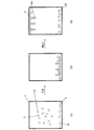
アッセイは、大きい方のチャンバ15を、(フィルホール17を介して、)TSHへの抗体で覆われた200nmコロイド金粒子を含む緩衝剤混合物と、更に5ng/mLの濃度のTSHで満たすことで行われる。制御チャンバ16は、TSHなしで、(同一濃度の)緩衝剤及び金粒子だけで同時に満たされる。入口ホール及び出口ホールが封止され、次に、圧電フィルム3がチャンバの底面上で水平に配向されるよう、チャンバアセンブリが試験器具(test instrument)に接続される。次に、圧電フィルム3は、(波長525nmの)4つのLEDを用いて連続して、刻まれたLED光で照射される。4つのLEDのうちの3つは、リードチャンバの表面の異なる領域を照射し、1つは、制御チャンバ16の圧電フィルム表面を照射する。各LEDパルスについて、電圧が、ロックイン増幅器及びアナログ・デジタル(ADC)変換器を用いて、圧電フィルム3をまたいで測定される。ADC信号が、時間に対しプロットされ、図4に示されている。ADC信号が、最初の1200秒にわたって上昇することが観察できる。これは、照射された金粒子がフィルムの表面に堆積するにつれて、圧電フィルム3中に誘起される熱応力が増加したことを示している。1200秒後には、制御チャンバ(LED1)及び測定チャンバ(LED2、3、及び4)からの信号は、見分けがつかなくなる。
The assay consists of filling the larger chamber 15 (through fill hole 17) with a buffer mixture containing 200 nm colloidal gold particles covered with antibodies to TSH and a further 5 ng / mL concentration of TSH. Done. The
この時点で、チャンバが反転され、その結果、圧電フィルム3が、チャンバの上部、即ち、「屋根」を形成する(これは、図2(c)の位置に相当する)。重力のもとで金粒子が表面から離れるにつれて、制御チャンバ(LED1)内の信号が急激に低下したことが観測できる。しかしながら、測定チャンバ(LED2、3、及び4)では、信号の低下は、ずっと少ない。理由は、サンプル中に存在するTSHが、金粒子上の抗体と表面上の抗体との間を架橋(bridge)し、金粒子を圧電フィルム3の表面に結合させるからである。
At this point, the chamber is inverted so that the
これらのプロット間の差は、TSHが反応混合物内に存在することを確認するのに使用可能である。加えて、TSHの異なる濃度を用いた調節曲線(calibration curve)を用意することで、このシステムを、人体流体(human fluid)中のTSH濃度についての定量的試験として使用することが可能である。 The difference between these plots can be used to confirm that TSH is present in the reaction mixture. In addition, by providing a calibration curve using different concentrations of TSH, this system can be used as a quantitative test for TSH concentrations in human fluid.
Claims (15)
エネルギーの変化を電気的信号に変換することが可能な変換器に、前記サンプルをさらすステップであって、前記変換器は、前記変換器上に又は前記変換器に近接して少なくとも1つの連結試薬を有し、前記少なくとも1つの連結試薬は、前記検体と結合することが可能な結合部位を有する、ステップと、
標識化試薬を前記サンプル中に導入するステップであって、前記標識化試薬は、前記検体用又は前記連結試薬用の結合部位と、エネルギーを生成するよう、放射源により生成された電磁放射を吸収することが可能な標識とを含む、ステップと、
前記標識化試薬を、第1の期間において、前記検体又は前記連結試薬と結合させるステップであって、前記変換器は、前記標識化試薬が、少なくとも部分的に前記変換器上に定着されるよう方向付けられている、ステップと、
続いて、第2の期間において、前記変換器を、前記サンプルに対し反転させる又は部分的に反転させることで、前記連結試薬に直接的にも前記検体を介しても未結合の前記標識化試薬を前記変換器から分離させるステップと、
前記第1及び第2の期間の間において、前記サンプルに電磁放射を照射するステップと、
前記生成されたエネルギーを電気的信号に変換するステップと、
前記電気的信号を検出するステップと、
を含む方法。 A method for detecting an analyte in a sample, comprising:
Subjecting the sample to a transducer capable of converting a change in energy into an electrical signal, the transducer comprising at least one linking reagent on or in proximity to the transducer The at least one linking reagent has a binding site capable of binding to the analyte, and
Introducing a labeling reagent into the sample, wherein the labeling reagent absorbs electromagnetic radiation generated by a radiation source to generate binding sites for the analyte or the linking reagent and energy. A step including a sign that can be
Binding the labeling reagent to the analyte or the linking reagent in a first period of time, wherein the converter causes the labeling reagent to be at least partially fixed on the converter. Oriented, steps,
Subsequently, in the second period, the labeling reagent that is not bound to the linking reagent either directly or via the analyte by inverting or partially inverting the converter with respect to the sample. Separating from the converter;
Irradiating the sample with electromagnetic radiation between the first and second time periods;
Converting the generated energy into an electrical signal;
Detecting the electrical signal;
Including methods.
電磁放射を生成するよう適合された放射源と、
エネルギーの変化を電気的信号に変換することが可能な変換器と、
前記変換器上の又は前記変換器に近接した少なくとも1つの連結試薬であって、前記検体と結合することが可能な結合部位を有する少なくとも1つの連結試薬と、
前記サンプルを、流体中に変換器と接して保持するためのチャンバであって、ふたで又は毛細力により封止されたチャンバと、
前記変換器により生成された前記電気的信号を検出することが可能な検出器とを備え、
前記装置は、固定リーダー内の回転カセットを備え、前記カセットは、前記チャンバと前記変換器とを含む、装置。 An apparatus for detecting an analyte in a sample,
A radiation source adapted to generate electromagnetic radiation; and
A converter capable of converting a change in energy into an electrical signal;
At least one linking reagent on or near the converter, the binding reagent having a binding site capable of binding to the analyte;
A chamber for holding the sample in fluid contact with the transducer, the chamber sealed with a lid or by capillary force;
A detector capable of detecting the electrical signal generated by the converter;
The apparatus comprises a rotating cassette in a fixed reader, the cassette including the chamber and the transducer.
Applications Claiming Priority (5)
| Application Number | Priority Date | Filing Date | Title |
|---|---|---|---|
| US96930907P | 2007-08-31 | 2007-08-31 | |
| GB0716968.3 | 2007-08-31 | ||
| US60/969,309 | 2007-08-31 | ||
| GBGB0716968.3A GB0716968D0 (en) | 2007-08-31 | 2007-08-31 | Sensor |
| PCT/GB2008/050699 WO2009027726A1 (en) | 2007-08-31 | 2008-08-13 | Sensor |
Publications (3)
| Publication Number | Publication Date |
|---|---|
| JP2010538253A JP2010538253A (en) | 2010-12-09 |
| JP2010538253A5 JP2010538253A5 (en) | 2011-08-25 |
| JP5749010B2 true JP5749010B2 (en) | 2015-07-15 |
Family
ID=38617072
Family Applications (1)
| Application Number | Title | Priority Date | Filing Date |
|---|---|---|---|
| JP2010522454A Expired - Fee Related JP5749010B2 (en) | 2007-08-31 | 2008-08-13 | Sensor |
Country Status (8)
| Country | Link |
|---|---|
| US (2) | US8524504B2 (en) |
| EP (1) | EP2185932B1 (en) |
| JP (1) | JP5749010B2 (en) |
| CN (1) | CN101815942B (en) |
| CA (1) | CA2695213C (en) |
| ES (1) | ES2530673T3 (en) |
| GB (1) | GB0716968D0 (en) |
| WO (1) | WO2009027726A1 (en) |
Families Citing this family (6)
| Publication number | Priority date | Publication date | Assignee | Title |
|---|---|---|---|---|
| GB2473220A (en) * | 2009-09-03 | 2011-03-09 | Vivacta Ltd | Analysis device comprising a transducer with stiffening elements |
| GB201000643D0 (en) * | 2010-01-15 | 2010-03-03 | Vivacta Ltd | A method for sensing a chemical |
| WO2012073182A1 (en) | 2010-11-30 | 2012-06-07 | Koninklijke Philips Electronics N.V. | A sensor device for magnetically actuated particles |
| GB201105828D0 (en) * | 2011-04-06 | 2011-05-18 | Vivacta Ltd | A device for detecting an analyte |
| CN102928606B (en) * | 2012-11-16 | 2015-10-07 | 武汉明德生物科技股份有限公司 | The Procalcitonin quick detection kit of multispecific antibody mark |
| JP6566704B2 (en) * | 2015-04-27 | 2019-08-28 | デンカ生研株式会社 | Immunochromatography apparatus with reduced background noise and method for reducing the same |
Family Cites Families (22)
| Publication number | Priority date | Publication date | Assignee | Title |
|---|---|---|---|---|
| GB8909701D0 (en) * | 1989-04-27 | 1989-06-14 | Health Lab Service Board | Analytical apparatus |
| CA2118522A1 (en) * | 1992-05-26 | 1993-12-09 | Robert M. Ippolito | Time dependent administration of oligosaccharides glycosides related to blood group determinants having a type i or type ii core structure in reducing inflammation in a sensitized mammal arising from exposure to an antigen |
| US5858666A (en) * | 1996-08-29 | 1999-01-12 | Biotechnology Research And Development Corporation | Apparatus and method of detection employing an AC frequency sensor array |
| US6346376B1 (en) * | 1998-06-03 | 2002-02-12 | Centre Suisse D'electronique Et De Mictotechnique Sa | Optical sensor unit and procedure for the ultrasensitive detection of chemical or biochemical analytes |
| EP1151139A2 (en) * | 1999-01-25 | 2001-11-07 | UT-Battelle, LLC | Multifunctional and multispectral biosensor devices and methods of use |
| JP2002122597A (en) * | 2000-08-09 | 2002-04-26 | Mitsubishi Chemicals Corp | Chip for measuring object to be measured, equipment and method for measuring object |
| US20030170148A1 (en) * | 2001-01-31 | 2003-09-11 | Mcentee John F. | Reaction chamber roll pump |
| US6899714B2 (en) | 2001-10-03 | 2005-05-31 | Vaughan Medical Technologies, Inc. | Vertebral stabilization assembly and method |
| EP1528912A2 (en) | 2002-07-18 | 2005-05-11 | Quest International Services B.V. | Perfume compositions |
| GB0308324D0 (en) * | 2003-04-10 | 2003-05-14 | Piezoptic Ltd | A chemical sensing device |
| EP1628754A2 (en) * | 2003-06-05 | 2006-03-01 | Bioprocessors Corporation | Apparatus and method for manipulating substrates |
| JP3816502B2 (en) | 2003-08-04 | 2006-08-30 | 博 冨安 | Method for oxidizing organic substances using supercritical water or subcritical water |
| JP2005319407A (en) * | 2004-05-10 | 2005-11-17 | Hitachi Ltd | Instrument using piezoelectric device |
| KR20070035005A (en) | 2004-07-20 | 2007-03-29 | 슈비하크 아게 | Horizontal sleepers with adjusting device for trains |
| US7169617B2 (en) * | 2004-08-19 | 2007-01-30 | Fujitsu Limited | Device and method for quantitatively determining an analyte, a method for determining an effective size of a molecule, a method for attaching molecules to a substrate, and a device for detecting molecules |
| WO2006134546A2 (en) * | 2005-06-17 | 2006-12-21 | Koninklijke Philips Electronics N.V. | Accurate magnetic biosensor |
| EP1906705B1 (en) | 2005-07-15 | 2013-04-03 | Panasonic Corporation | Signal processing device |
| HUP0500730A2 (en) | 2005-07-29 | 2007-02-28 | Richter Gedeon Vegyuszeti Gyar | 1,2-diaryl-heterocyclic compounds, their preparation, pharmaceutical compositions comprising thereof and their use |
| WO2007106868A2 (en) * | 2006-03-14 | 2007-09-20 | University Of Rochester | Cell culture devices having ultrathin porous membrane and uses thereof |
| CA2643169A1 (en) * | 2006-03-17 | 2007-09-27 | Vivacta Ltd | A chemical sensing device |
| JP2010533281A (en) * | 2006-06-06 | 2010-10-21 | ビバクタ、リミテッド | Chemical substance detection method |
| US20080026451A1 (en) * | 2006-06-15 | 2008-01-31 | Braman Jeffrey C | System for isolating biomolecules from a sample |
-
2007
- 2007-08-31 GB GBGB0716968.3A patent/GB0716968D0/en not_active Ceased
-
2008
- 2008-08-13 WO PCT/GB2008/050699 patent/WO2009027726A1/en active Application Filing
- 2008-08-13 US US12/675,684 patent/US8524504B2/en not_active Expired - Fee Related
- 2008-08-13 JP JP2010522454A patent/JP5749010B2/en not_active Expired - Fee Related
- 2008-08-13 CN CN2008801046876A patent/CN101815942B/en not_active Expired - Fee Related
- 2008-08-13 EP EP08788670.1A patent/EP2185932B1/en not_active Not-in-force
- 2008-08-13 CA CA2695213A patent/CA2695213C/en not_active Expired - Fee Related
- 2008-08-13 ES ES08788670T patent/ES2530673T3/en active Active
-
2013
- 2013-07-30 US US13/954,582 patent/US9638691B2/en not_active Expired - Fee Related
Also Published As
| Publication number | Publication date |
|---|---|
| CN101815942A (en) | 2010-08-25 |
| GB0716968D0 (en) | 2007-10-10 |
| EP2185932A1 (en) | 2010-05-19 |
| ES2530673T3 (en) | 2015-03-04 |
| JP2010538253A (en) | 2010-12-09 |
| WO2009027726A1 (en) | 2009-03-05 |
| EP2185932B1 (en) | 2015-01-28 |
| US20130315783A1 (en) | 2013-11-28 |
| US20100285609A1 (en) | 2010-11-11 |
| CA2695213A1 (en) | 2009-03-05 |
| US9638691B2 (en) | 2017-05-02 |
| CN101815942B (en) | 2013-09-11 |
| US8524504B2 (en) | 2013-09-03 |
| CA2695213C (en) | 2017-01-10 |
Similar Documents
| Publication | Publication Date | Title |
|---|---|---|
| US20090087862A1 (en) | Chemical Sensing Device | |
| JP4511522B2 (en) | Photochemical sensing device with pyroelectric or piezoelectric transducer | |
| US9638691B2 (en) | Sensor | |
| US20090203154A1 (en) | Method for Sensing a Chemical | |
| CA2719010C (en) | A method for sensing a chemical | |
| US8084002B2 (en) | Chemical sensing device | |
| US20110111428A1 (en) | Method for Sensing a Chemical | |
| EP2265951B1 (en) | A method for sensing a chemical |
Legal Events
| Date | Code | Title | Description |
|---|---|---|---|
| A521 | Request for written amendment filed |
Free format text: JAPANESE INTERMEDIATE CODE: A523 Effective date: 20110705 |
|
| A621 | Written request for application examination |
Free format text: JAPANESE INTERMEDIATE CODE: A621 Effective date: 20110705 |
|
| A977 | Report on retrieval |
Free format text: JAPANESE INTERMEDIATE CODE: A971007 Effective date: 20121121 |
|
| A131 | Notification of reasons for refusal |
Free format text: JAPANESE INTERMEDIATE CODE: A131 Effective date: 20130614 |
|
| A601 | Written request for extension of time |
Free format text: JAPANESE INTERMEDIATE CODE: A601 Effective date: 20130913 |
|
| A602 | Written permission of extension of time |
Free format text: JAPANESE INTERMEDIATE CODE: A602 Effective date: 20130924 |
|
| A601 | Written request for extension of time |
Free format text: JAPANESE INTERMEDIATE CODE: A601 Effective date: 20131015 |
|
| A602 | Written permission of extension of time |
Free format text: JAPANESE INTERMEDIATE CODE: A602 Effective date: 20131022 |
|
| A131 | Notification of reasons for refusal |
Free format text: JAPANESE INTERMEDIATE CODE: A131 Effective date: 20140328 |
|
| A521 | Request for written amendment filed |
Free format text: JAPANESE INTERMEDIATE CODE: A523 Effective date: 20140526 |
|
| A131 | Notification of reasons for refusal |
Free format text: JAPANESE INTERMEDIATE CODE: A131 Effective date: 20141003 |
|
| A521 | Request for written amendment filed |
Free format text: JAPANESE INTERMEDIATE CODE: A523 Effective date: 20141112 |
|
| TRDD | Decision of grant or rejection written | ||
| A01 | Written decision to grant a patent or to grant a registration (utility model) |
Free format text: JAPANESE INTERMEDIATE CODE: A01 Effective date: 20150417 |
|
| A61 | First payment of annual fees (during grant procedure) |
Free format text: JAPANESE INTERMEDIATE CODE: A61 Effective date: 20150513 |
|
| R150 | Certificate of patent or registration of utility model |
Ref document number: 5749010 Country of ref document: JP Free format text: JAPANESE INTERMEDIATE CODE: R150 |
|
| R250 | Receipt of annual fees |
Free format text: JAPANESE INTERMEDIATE CODE: R250 |
|
| LAPS | Cancellation because of no payment of annual fees |