JP5747710B2 - Label conveying apparatus and label sheet joint specifying method - Google Patents
Label conveying apparatus and label sheet joint specifying method Download PDFInfo
- Publication number
- JP5747710B2 JP5747710B2 JP2011160722A JP2011160722A JP5747710B2 JP 5747710 B2 JP5747710 B2 JP 5747710B2 JP 2011160722 A JP2011160722 A JP 2011160722A JP 2011160722 A JP2011160722 A JP 2011160722A JP 5747710 B2 JP5747710 B2 JP 5747710B2
- Authority
- JP
- Japan
- Prior art keywords
- sheet
- label
- value
- sensor output
- specified
- Prior art date
- Legal status (The legal status is an assumption and is not a legal conclusion. Google has not performed a legal analysis and makes no representation as to the accuracy of the status listed.)
- Expired - Fee Related
Links
Images


Classifications
-
- B—PERFORMING OPERATIONS; TRANSPORTING
- B41—PRINTING; LINING MACHINES; TYPEWRITERS; STAMPS
- B41J—TYPEWRITERS; SELECTIVE PRINTING MECHANISMS, i.e. MECHANISMS PRINTING OTHERWISE THAN FROM A FORME; CORRECTION OF TYPOGRAPHICAL ERRORS
- B41J3/00—Typewriters or selective printing or marking mechanisms characterised by the purpose for which they are constructed
- B41J3/407—Typewriters or selective printing or marking mechanisms characterised by the purpose for which they are constructed for marking on special material
- B41J3/4075—Tape printers; Label printers
-
- B—PERFORMING OPERATIONS; TRANSPORTING
- B41—PRINTING; LINING MACHINES; TYPEWRITERS; STAMPS
- B41J—TYPEWRITERS; SELECTIVE PRINTING MECHANISMS, i.e. MECHANISMS PRINTING OTHERWISE THAN FROM A FORME; CORRECTION OF TYPOGRAPHICAL ERRORS
- B41J11/00—Devices or arrangements of selective printing mechanisms, e.g. ink-jet printers or thermal printers, for supporting or handling copy material in sheet or web form
- B41J11/0095—Detecting means for copy material, e.g. for detecting or sensing presence of copy material or its leading or trailing end
Landscapes
- Handling Of Sheets (AREA)
- Controlling Sheets Or Webs (AREA)
Description
本発明は、ラベル搬送装置、及びラベルシートの繋ぎ目特定方法に関する。 The present invention relates to a label conveying device and a method for specifying a joint between label sheets.
商品や荷物などに貼り付けるラベルに印刷を行うラベルプリンターが知れられている。荷物(例えば、航空機の客の手荷物や預け荷物)に貼られたり、荷物の取っ手などに巻きつけられたりして使用されるラベルは、バゲージタグなどとも呼ばれる。 There is known a label printer that performs printing on a label to be attached to a product or a package. A label used by being attached to a baggage (for example, baggage or checked baggage of an aircraft passenger) or wound around a baggage handle or the like is also called a baggage tag.
このようなラベルは、例えば、剥離紙である台紙(以下、「シート」ともいう)に、一列に所定の間隔(以下、「ラベル間」ともいう)を空けて貼られた状態で提供される(以下、ラベルが貼られた状態のシートを「ラベルシート」ともいう)。ラベルは、使用の際には、シートから剥されて、商品や荷物に貼られる。ラベルシートは、例えば、ロール紙やファンフォールド紙(連続用紙)であり、ラベルごとにシートを切り離しできるように、ラベル間のシートにミシン目が開けられている。すなわち、このミシン目が、ラベルごとのシートの繋ぎ目となっている。この繋ぎ目は、ユーザーが手でカットしてもよいし、ラベルプリンターが自動でカットしてもよい。 Such a label is provided, for example, in a state where a predetermined interval (hereinafter also referred to as “between labels”) is provided in a row on a mount (hereinafter also referred to as “sheet”) which is a release paper. (Hereinafter, the sheet with the label attached is also referred to as “label sheet”). In use, the label is peeled off from the sheet and attached to a product or luggage. The label sheet is, for example, roll paper or fanfold paper (continuous paper), and perforations are opened in the sheets between the labels so that the sheets can be separated for each label. That is, this perforation is a joint between sheets for each label. The joint may be cut manually by the user or automatically by a label printer.
ラベルプリンターは、ラベルシートを所定方向に搬送し、各ラベルに印刷を行う。また、印刷が終了したラベルごとにシートを切り離すカッターを備えるものもある。そのため、ラベルプリンターは、一般的に、ラベルの端やラベル間の位置を検出するためのセンサーを備える。 The label printer conveys a label sheet in a predetermined direction and prints on each label. Some have a cutter that cuts off the sheet for each label that has been printed. Therefore, the label printer generally includes a sensor for detecting the end of the label and the position between the labels.
センサーとしては、例えば、ラベルシートの表裏面側にそれぞれ対向する位置に設けられた発光素子と受光素子により、搬送されるラベルシートを介して透過した光量を検出する透過センサーがある。ラベルプリンターは、透過光量の変化により、ラベルの端やラベル間のシート部分を検出する。また、センサーとしては、例えば、用紙の一面側に設けられた発光素子と受光素子により、搬送されるラベルシートに反射した光量を検出する反射センサーがある。ラベルプリンターは、反射光量の変化により、ラベルの端やラベル間のシート部分を検出する。 As the sensor, for example, there is a transmission sensor that detects the amount of light transmitted through the conveyed label sheet by a light emitting element and a light receiving element provided at positions facing the front and back sides of the label sheet. The label printer detects the edge of the label and the sheet portion between the labels based on the change in the amount of transmitted light. As a sensor, for example, there is a reflection sensor that detects the amount of light reflected on a conveyed label sheet by a light emitting element and a light receiving element provided on one side of the paper. The label printer detects the edge of the label and the sheet portion between the labels based on the change in the amount of reflected light.
特許文献1には、透過センサーを備えるラベルプリンターが記載されている。 Patent Document 1 describes a label printer including a transmission sensor.
ところで、同じ目的や用途で使用されるラベルシートであっても、複数の仕様のものが存在することがある。例えば、航空機の荷物に使用されるバゲージタグは、航空会社やバゲージタグの製造元などによって仕様が異なる。仕様としては、例えば、ラベル間のシートの繋ぎ目に孔が開いているもの、孔が開いていないもの、ラベルに、ラベルをシートから剥がし易くするためにスリットがあるもの、スリットがないもの、ラベルに、RFID(Radio Frequency IDentification)に使用される半導体素子やアンテナが埋め込まれたもの、埋め込まれていないもの、などがある。また、これらのラベルシートは、ラベルやシートの材質によって光の透過率や反射率が異なったり、温度変化や経年劣化によりラベル間やスリットの幅が変化したりすることがある。 By the way, even if it is a label sheet used for the same purpose and use, the thing of a some specification may exist. For example, baggage tags used for aircraft packages have different specifications depending on the airline and the manufacturer of the baggage tag. As specifications, for example, those with holes in the joint between sheets of labels, those with no holes, those with slits to make it easier to peel off labels from sheets, those without slits, There are labels in which semiconductor elements and antennas used for RFID (Radio Frequency IDentification) are embedded and those in which labels are not embedded. In addition, these label sheets may have different light transmittance and reflectance depending on the label and the material of the label, and may change between labels and the width of the slit due to temperature change and aging deterioration.
そのため、従来のラベルプリンターでは、ラベルシートが異なる仕様のものに変更された場合(例えば、ロールが交換された場合)や、ラベルシートの品質がばらついている場合などには、例えば、ラベルの端やラベル間の繋ぎ目を正しく認識することができず、ラベルシートのカットに失敗することがある。また、ラベルプリンターを正しく動作させるためには、例えば、ユーザーがラベルごとのシートの長さを手入力する必要があり、使い勝手が悪い。 Therefore, in a conventional label printer, when the label sheet is changed to one with a different specification (for example, when the roll is replaced) or when the quality of the label sheet varies, for example, the end of the label In some cases, the seam between labels cannot be correctly recognized, and cutting of the label sheet fails. In order to operate the label printer correctly, for example, the user needs to manually input the sheet length for each label, which is inconvenient.
そこで、本発明は、ラベルプリンターにおいて、ラベルシートの各シートの繋ぎ目を、より精度よく自動で特定することを目的とする。 SUMMARY OF THE INVENTION Accordingly, an object of the present invention is to automatically and accurately specify a joint between each sheet of a label sheet in a label printer.
上記の課題を解決するための本発明の一態様は、シートに複数のラベルを配列されたラベルシートを読み取ってセンサー出力値を出力するセンサーと、センサー出力値の最頻値を特定する最頻値特定手段と、前記ラベルシートの搬送方向において、前記センサー出力値が、前記最頻値に応じて決定したラベル間のシート部分を検出する前記センサー出力値が第一の閾値を超える第一のシート位置と、前記センサー出力値が前記第一の閾値よりも大きい値であって前記ラベルシートの孔を検出する前記センサー出力値が第二の閾値を超える第二のシート位置と、前記センサー出力値が前記第二の閾値を下回る第三のシート位置と、前記センサー出力値が前記第一の閾値を下回る第四のシート位置と、を特定するシート位置特定手段と、前記第一のシート位置及び前記第四のシート位置が特定されて前記第二のシート位置及び前記第三のシート位置が特定されていない場合、前記第一のシート位置から前記第四のシート位置までの第一区間の中央をラベル間のシートの繋ぎ目位置として特定し、前記第一のシート位置及び前記第四のシート位置が特定されて前記第二のシート位置及び前記第三のシート位置が特定されている場合、前記第二のシート位置から前記第三のシート位置までの第二区間の中央をラベル間のシートの繋ぎ目位置として特定する繋ぎ目位置特定手段と、を有する、ことを特徴とする。
One aspect of the present invention for solving the above problems is a sensor that reads a label sheet in which a plurality of labels are arranged on a sheet and outputs a sensor output value, and a mode that specifies a mode value of the sensor output value. and values specifying means, in the conveying direction of the label sheet, the sensor output value, the sensor output value is first in excess of a first threshold value for detecting a sheet portion between labels determined in accordance with the mode value of the seat position, and the sensor output value is a second seat position which exceeds the second threshold value to detect the hole of the label sheet to a value greater than the sensor output value is the first threshold value, the a third sheet position sensor output value that falls below the second threshold value, and the sheet position specifying means for the sensor output value is identified and a fourth sheet position that falls below the first threshold value, The first When the sheet position and the fourth sheet position are specified and the second sheet position and the third sheet position are not specified, the first position from the first sheet position to the fourth sheet position The center of the section is specified as the joint position of the sheet between the labels, the first sheet position and the fourth sheet position are specified, and the second sheet position and the third sheet position are specified. And a joint position specifying means for specifying the center of the second section from the second sheet position to the third sheet position as the joint position of the sheet between the labels. .
ここで、前記第一の閾値は、前記最頻値に所定値を加えた値である、ことを特徴としてもよい。 Here, the first threshold value may be a value obtained by adding a predetermined value to the mode value.
また、前記ラベル搬送装置は、前記センサー出力値の最大値を特定する最大値特定手段を備え、前記第一の閾値は、前記最頻値と前記最大値の差分に応じて決定した値である、ことを特徴としてもよい。この場合、前記ラベル搬送装置は、前記最頻値と前記最大値の差分の所定割合の値を前記最頻値に加えた値を前記第一の閾値として決定する閾値決定手段を有する、ことを特徴としてもよい。 The label conveying device includes a maximum value specifying unit that specifies a maximum value of the sensor output value, and the first threshold is a value determined according to a difference between the mode value and the maximum value. This may be a feature. In this case, the label conveying apparatus includes a threshold value determining unit that determines a value obtained by adding a value of a predetermined ratio of the difference between the mode value and the maximum value to the mode value as the first threshold value. It may be a feature.
また、前記繋ぎ目位置特定手段は、前記第一のシート位置及び前記第四のシート位置が特定された場合に、前記第二のシート位置及び前記第三のシート位置が特定されていない場合、前記第一区間の距離が所定距離を超えているか否かを判定し、前記第一区間の距離が前記所定距離を超えている場合に、前記第一区間の中央をラベル間のシートの繋ぎ目位置として特定する、ことを特徴としてもよい。 Further, the joint position specifying means, when the first sheet position and the fourth sheet position are specified, when the second sheet position and the third sheet position are not specified, It is determined whether or not the distance of the first section exceeds a predetermined distance, and when the distance of the first section exceeds the predetermined distance, the center of the first section is connected to the sheet joint between the labels. It is good also as a characteristic to specify as a position.
また、前記繋ぎ目位置特定手段は、前記第一のシート位置及び前記第四のシート位置が特定された場合に、前記第二のシート位置及び前記第三のシート位置が特定されていない場合、前記第一区間の距離が所定距離を超えているか否かを判定し、前記第一区間の距離が前記所定距離を超えていない場合に、ラベル間のシートの繋ぎ目位置を特定せずに、少なくとも特定された前記第一のシート位置及び前記第四のシート位置をリセットする、ことを特徴としてもよい。 Further, the joint position specifying means, when the first sheet position and the fourth sheet position are specified, when the second sheet position and the third sheet position are not specified, It is determined whether or not the distance of the first section exceeds a predetermined distance, and when the distance of the first section does not exceed the predetermined distance, without specifying the joint position of the sheet between the labels, At least the first sheet position and the fourth sheet position specified may be reset.
また、前記最頻値特定手段は、前記ラベルシートの搬送の開始後、第一の所定区間のセンサー出力値を用いて前記最頻値を特定し、前記シート位置特定手段は、前記所定区間よりも搬送方向後方の区間のセンサー出力値を用いて前記各シート位置を特定する、ことを特徴としてもよい。 Further, the mode value specifying means specifies the mode value using a sensor output value of a first predetermined section after the start of conveyance of the label sheet, and the sheet position specifying means is based on the predetermined section. Also, each sheet position may be specified using a sensor output value in a section rearward in the conveyance direction.
また、前記最頻値特定手段は、前記ラベルシートの搬送の開始後、継続的に前記センサー出力値を用いて随時前記最頻値を特定して更新する、ことを特徴としてもよい。 Further, the mode value specifying means may specify and update the mode value at any time using the sensor output value continuously after the conveyance of the label sheet is started.
また、前記ラベルには、識別情報を記憶するチップ及び当該識別情報を送受信するアンテナが第二の所定区間に設けられており、前記最頻値特定手段は、前記第二の所定区間のセンサー出力値を前記最頻値の特定に使用しない、ことを特徴としてもよい。 The label is provided with a chip for storing identification information and an antenna for transmitting and receiving the identification information in a second predetermined section, and the mode value specifying means outputs the sensor output of the second predetermined section. A value may not be used to specify the mode value.
また、前記位置特定手段は、前記第一区間の中央がラベル間のシートの繋ぎ目位置として特定された以降、さらに搬送された区間のセンサー出力値を用いて、前記第二のシート位置と、前記第三のシート位置とを特定し、前記繋ぎ目位置特定手段は、前記第二シート位置及び前記第三シート位置が特定されなかった場合に、前記第一区間の中央をラベル間のシートの繋ぎ目位置として特定し、前記第二シート位置及び前記第三シート位置が特定された場合に、前記第二のシート位置から前記第三のシート位置までの第二区間の中央をラベル間のシートの繋ぎ目位置として特定する、ことを特徴としてもよい。 Further, the position specifying means, after the center of the first section is specified as a sheet joint position between labels, using the sensor output value of the further conveyed section, the second sheet position, The third sheet position is specified, and the joint position specifying means determines the center of the first section of the sheet between the labels when the second sheet position and the third sheet position are not specified. When the second sheet position and the third sheet position are specified as the joint position, the sheet between the labels is the center of the second section from the second sheet position to the third sheet position. It is good also as specifying as a joint position of.
また、前記センサーは、前記ラベルシートを挟んで対向配置された、発光素子及び受光素子、又は超音波発信素子及び超音波受信素子である、ことを特徴としてもよい。 The sensor may be a light emitting element and a light receiving element, or an ultrasonic transmitting element and an ultrasonic receiving element, which are disposed to face each other with the label sheet interposed therebetween.
また、前記センサーは、前記ラベルシートの搬送方向と直交する方向に並ぶ複数の位置において前記ラベルシートを読み取り、前記複数の位置毎にセンサー出力値を出力可能とする、ことを特徴としてもよい。 The sensor may read the label sheet at a plurality of positions arranged in a direction orthogonal to the conveyance direction of the label sheet and output a sensor output value at each of the plurality of positions.
ここで、前記最頻値特定手段、前記シート位置特定手段、及び繋ぎ目位置特定手段は、前記複数の位置に対応したセンサー出力値毎に機能可能であり、前記複数の位置に対応したセンサーのうち、最初に前記第一のシート位置を特定するセンサー出力値を出力したセンサーを、以降の前記各シート位置を特定するためのセンサーとして用いる、ことを特徴としてもよい。 Here, the mode value specifying means, the sheet position specifying means, and the joint position specifying means can function for each sensor output value corresponding to the plurality of positions, and the sensor corresponding to the plurality of positions. Among them, a sensor that first outputs a sensor output value that specifies the first sheet position may be used as a sensor for specifying each subsequent sheet position.
また、前記最頻値特定手段、前記シート位置特定手段、及び繋ぎ目位置特定手段は、前記複数の位置に対応したセンサー出力値毎に機能可能であり、前記複数の位置に対応したセンサーのうち、最初に前記繋ぎ目位置を特定するセンサー出力値を出力したセンサーを、以降の前記各シート位置を特定するためのセンサーとして用いる、ことを特徴としてもよい。 Further, the mode value specifying means, the sheet position specifying means, and the joint position specifying means can function for each sensor output value corresponding to the plurality of positions, and among the sensors corresponding to the plurality of positions. A sensor that first outputs a sensor output value that specifies the joint position may be used as a sensor for specifying each subsequent sheet position.
また、前記最頻値特定手段、前記シート位置特定手段、及び繋ぎ目位置特定手段は、前記複数の位置に対応したセンサー出力値毎に機能可能であり、前記センサー出力値毎に特定される前記各シート位置に基づき、前記ラベル間のシート部分の形状を判別する判別手段を有する、ことを特徴としてもよい。 Further, the mode value specifying means, the sheet position specifying means, and the joint position specifying means can function for each sensor output value corresponding to the plurality of positions, and are specified for each sensor output value. It is good also as having the discriminating means which discriminates the shape of the sheet portion between the labels based on each sheet position.
上記の課題を解決するための本発明の他の態様は、シートに複数のラベルが配列されたラベルシートを搬送し、前記ラベルシートを読み取ってセンサー出力値を出力し、センサー出力値の最頻値を特定し、前記ラベルシートの搬送方向で、前記最頻値に応じて決定したラベル間のシート部分を検出する前記センサー出力値が第一の閾値を超える第一のシート位置を特定し、前記ラベルシートの搬送方向で、前記センサー出力値が前記第一の閾値よりも大きい値であって前記ラベルシートの孔を検出する前記センサー出力値が第二の閾値を超える第二のシート位置を特定し、前記ラベルシートの搬送方向で、前記センサー出力値が、前記第二の閾値を下回る第三のシート位置を特定し、前記ラベルシートの搬送方向で、前記センサー出力値が前記第一の閾値を下回る第四のシート位置を特定し、前記第四のシート位置が特定された際に、前記第二のシート位置及び前記第三のシート位置が特定されていない場合、前記第一のシート位置から前記第四のシート位置までの第一区間の中央をラベル間のシートの繋ぎ目位置として特定し、前記第四のシート位置が特定された際に、前記第二のシート位置及び前記第三のシート位置が特定されている場合、前記第二のシート位置から前記第三のシート位置までの第二区間の中央をラベル間のシートの繋ぎ目位置として特定することを特徴とする。 According to another aspect of the present invention for solving the above-described problem, a label sheet in which a plurality of labels are arranged on a sheet is conveyed, the label sheet is read, a sensor output value is output, and the most frequent sensor output value is obtained. to determine the value, in the conveying direction of the label sheet, and identifies the first seat position the sensor output value to detect the sheet portion is in excess of the first threshold between the label determined according to the mode value the in conveying direction of the label sheet, the sensor output value is said sensor output values to detect the hole of the label sheet to a value larger than the first threshold value is the second exceeds the second threshold value sheet position to identify, in the conveying direction of the label sheet, the sensor output value, to identify a third sheet position that falls below the second threshold value, the conveying direction of the label sheet, the sensor output value Previous If identifying the fourth sheet position that falls below a first threshold value, when the fourth sheet position is specified, the second seat position and the third sheet position is not specified, When the center of the first section from the first sheet position to the fourth sheet position is specified as the joint position of the sheet between the labels, the second sheet position is specified when the fourth sheet position is specified. When the sheet position and the third sheet position are specified, the center of the second section from the second sheet position to the third sheet position is specified as the sheet joint position between the labels. Features.
上記した以外の課題、構成、及び効果は、以下の実施形態の説明により明らかにされる。 Problems, configurations, and effects other than those described above will be clarified by the following description of embodiments.
以下、本発明の一実施形態について、図面を参照して説明する。 Hereinafter, an embodiment of the present invention will be described with reference to the drawings.
本実施形態では、ラベル搬送装置としてラベルプリンターを例に挙げて説明する。 In the present embodiment, a label printer will be described as an example of the label transport device.
本実施形態のラベルプリンターは、ラベルシートを搬送するとともに、透過センサーによりラベルシートを走査し、取得したセンサー出力値に基づいてラベル間のシートの繋ぎ目の位置を特定する。 The label printer of this embodiment conveys a label sheet, scans the label sheet with a transmission sensor, and specifies the position of the sheet joint between the labels based on the acquired sensor output value.
本実施形態のラベルプリンターは、例えば、ラベルシートのロールを交換するたびに、まず、ロールの先頭(ラベル間のシートの繋ぎ目が正しく切断された状態のラベルシートの始端)から、少なくともラベル一枚分のシートを含む所定距離を搬送することで、次のシートの繋ぎ目を特定し、ラベル一枚分のラベルシートの長さ(繋ぎ目から次の繋ぎ目までの長さ)を特定する。ラベル一枚分のラベルシートの長さを算出した後は、そのロールが交換されるまで、算出した長さの搬送を行うごとにラベルシートをカットする。もちろん、ラベルごとにシートの繋ぎ目位置を特定してカットするようにしてもよい。 For example, each time the label sheet roll is replaced, the label printer according to the present embodiment first has at least one label from the top of the roll (the beginning of the label sheet in a state where the sheet joint between the labels is correctly cut). By conveying a predetermined distance including sheets, specify the joint of the next sheet, and specify the length of the label sheet for one label (the length from the joint to the next joint). . After calculating the length of one label sheet, the label sheet is cut every time the calculated length is conveyed until the roll is replaced. Of course, the sheet joint position may be specified and cut for each label.
なお、ラベルプリンターは、例えば、紙送りモーターのステップ数などに基づいてラベルシートの搬送距離を検出できるため、シートの繋ぎ目位置が特定できれば、ラベル一枚分のラベルシートの長さを特定できる。 Since the label printer can detect the transport distance of the label sheet based on, for example, the number of steps of the paper feed motor, if the sheet joint position can be specified, the length of the label sheet for one label can be specified. .
図1は、本発明の一実施形態に係るラベルプリンターの概略構成の一例を示す図である。 FIG. 1 is a diagram illustrating an example of a schematic configuration of a label printer according to an embodiment of the present invention.
ラベルプリンター1は、コントローラー10と、操作パネル20と、印刷ユニット30と、ラベル検出ユニット40とを備える。ラベルプリンター1では、その給紙口側から排紙口側に向かって、ラベル検出ユニット40、印刷ヘッド32及びプラテンローラー33、カッター34の順に配置されている。
The label printer 1 includes a
コントローラー10は、ラベルプリンター1を統合的に制御するユニットである。
The
コントローラー10は、CPU11と、RAM12と、ROM13とを備える。CPU11は、例えば、ROM13からRAM12に所定のプログラムを読み出して実行することにより、他の各種ユニットを制御し、ラベルプリンター1の機能を実現する。
The
もちろん、コントローラー10は、操作パネル20、印刷ユニット30、及びラベル検出ユニット40のそれぞれを制御するためのインターフェイス回路や駆動回路などを備えていてもよい。これらの回路は、コントローラー10の外側に設けられていてもよい。
Of course, the
コントローラー10は、例えば、印刷ユニット30の各種装置(紙送りモーター31、印刷ヘッド32、カッター34)の動作を制御することにより、ラベルシートの搬送、ラベルに対する印刷、ラベルシートのカットを行う。また、コントローラー10は、例えば、ラベルシートの搬送とともに、ラベル検出ユニット40から出力されるセンサー出力値を取得し、ラベル間のシートの繋ぎ目の位置を特定する。なお、コントローラー10は、例えば、紙送りモーター31のステップ数に基づく走査位置とその位置のセンサー出力値とを対応付けてRAM12などに記憶する。
For example, the
操作パネル20は、ラベルプリンター1とユーザーの入出力インターフェイスである。操作パネル20は、例えば、ディスプレイと入力装置とを備える。操作パネル20は、例えば、コントローラー10の指示に従って、各種画面をディスプレイに表示する。また、操作パネル20は、入力装置の操作内容をコントローラー10に通知する。
The
印刷ユニット30は、ラベルに印刷を行うユニットである。印刷ユニット30は、例えば、紙送りモーター31と、印刷ヘッド32と、プラテンローラー33と、カッター34とを備える。
The
紙送りモーター31は、例えば、ステッピングモーターであり、コントローラー10の制御により所定角度ずつ(1ステップずつ)回転し、ギアなどを介してプラテンローラー33やその他の紙送りローラー(不図示)を回転させる。ラベルシートは、プラテンローラー33やその他の紙送りローラーの回転により所定の搬送方向に搬送される。
The
印刷ヘッド32は、例えば、感熱ヘッドであり、プラテンローラー33により圧接されたラベルシートのラベルに印刷を行う。印刷ヘッド32は、コントローラー10から送られた制御データに基づいて印字を行う。
The
カッター34は、ラベルシートを切断するユニットである。カッター34は、例えば、ラベルシートを挟むように上刃34aと、下刃34bとを備え、いずれか一方又は双方を上下動させることでラベルシートの切断を行う。カッター34は、コントローラー10の制御によりラベルシートの切断を行う。
The cutter 34 is a unit that cuts the label sheet. The cutter 34 includes, for example, an
ラベル検出ユニット40は、透過センサーである。ラベル検出ユニット40は、例えば、受光素子40aと、発光素子40bとを備える。受光素子40a及び発光素子40bは、搬送されるラベルシートの表裏面側にそれぞれ対向する位置に設けられる。ラベル検出ユニット40は、例えば、所定の搬送距離ごと(1又は2以上のステップごと)に、受光素子40aによりラベルシートを介して透過した光量を検出し、電圧値などのデジタルデータに変換してセンサー出力値としてコントローラー10に出力する。
The label detection unit 40 is a transmission sensor. The label detection unit 40 includes, for example, a
なお、本実施形態では、センサー出力値が高いほど透過率が高いものとする。 In the present embodiment, the higher the sensor output value, the higher the transmittance.
本実施形態の受光素子40aは、例えば、図2に示すように、ラベルシートの搬送方向と直交する方向に一列に配列された、1〜nの複数の受光素子で構成することができる。ラベル検出ユニット40は、各受光素子で検出された光量を、センサー出力値としてコントローラー10に出力する。コントローラー10は、素子ごとに、そのセンサー出力値を取得し、シートの繋ぎ目位置を特定することができる。
For example, as shown in FIG. 2, the
なお、発光素子40bは、例えば、受光素子40aの受光素子それぞれに対応するLEDなどの発光素子で構成することができる。もちろん、発光素子40bの構成はこれに限られない。
In addition, the
もちろん、ラベル検出ユニット40の構成は、上記に限られず、例えば、ラベルシートの表裏面側に対向する位置に設けられる、超音波受信素子及び超音波発信素子であってもよい。また、透過センサーではなく、反射センサーで構成されてもよい。 Of course, the configuration of the label detection unit 40 is not limited to the above, and may be, for example, an ultrasonic receiving element and an ultrasonic transmitting element provided at positions facing the front and back sides of the label sheet. Further, instead of the transmission sensor, a reflection sensor may be used.
図1に戻って、ラベルシートは、例えば、剥離紙であるシートと、当該シートの片面に一列に所定の間隔(ラベル間X)を空けて貼られたラベルとからなる。ラベルシートは、例えば、ロール紙やファンフォールド紙(連続用紙)であり、ラベルごとにシートを切り離しできるように、ラベル間Xの中央に繋ぎ目であるミシン目が開けられている。なお、ラベルシートの各種仕様については図4を参照して後述する。 Returning to FIG. 1, the label sheet includes, for example, a sheet that is release paper and a label that is pasted on one side of the sheet with a predetermined interval (inter-label X). The label sheet is, for example, roll paper or fanfold paper (continuous paper), and a perforation that is a joint is opened at the center of the X between the labels so that the sheet can be separated for each label. Various specifications of the label sheet will be described later with reference to FIG.
ラベルプリンター1の外観は、例えば、図3に示すように、背面にラベルシートを給紙する給紙口を備える。また、正面にラベルシートを排紙する排紙口を備える。ラベルシートは、給紙口に挿入され、不図示のラベルプリンター1内の搬送路に沿って、排紙口に向かって搬送される。ラベルシートのロール紙やファンフォールド紙は、例えば、ラベルプリンター1とは別の装置(不図示)に装填され、ラベルプリンター1によりラベルシートが引っ張られることにより、当該別の装置から順に繰り出される。 The external appearance of the label printer 1 includes, for example, a paper feed port for feeding a label sheet on the back as shown in FIG. In addition, a discharge port for discharging the label sheet is provided on the front. The label sheet is inserted into the paper feed port and conveyed toward the paper discharge port along a conveyance path in the label printer 1 (not shown). For example, the roll paper or fanfold paper of the label sheet is loaded into an apparatus (not shown) different from the label printer 1 and pulled out from the other apparatus in order by the label printer 1 pulling the label sheet.
図4は、ラベルシートの仕様例を示す図である。本図では、三つのラベルシート(A)〜(C)が例示されている。本図では、繋ぎ目から繋ぎ目までのラベル一枚分のラベルシート(ラベル(n)を含むラベルシート)と、その前後のラベルシート(ラベル(n−1)を含むラベルシートとラベル(n+1)を含むラベルシート)の一部が表されている。 FIG. 4 is a diagram illustrating a specification example of a label sheet. In this figure, three label sheets (A) to (C) are illustrated. In this figure, one label sheet (label sheet including label (n)) from the joint to the joint, and label sheets and labels (n + 1 including the label (n−1)) before and after the label sheet. )) Part of the label sheet) is represented.
ラベルシート(A)は、ラベル間の中央に、搬送方向と直交する方向に、繋ぎ目であるミシン目が設けられており、さらに、ミシン目に沿って、シート孔が二つ設けられている。シート孔は、繋ぎ目の位置をセンサーにより検出し易いように設けられた部材である。 The label sheet (A) is provided with a perforation which is a joint in a direction perpendicular to the conveyance direction in the center between the labels, and further, two sheet holes are provided along the perforation. . The sheet hole is a member provided so that the position of the joint can be easily detected by the sensor.
ラベルシート(B)は、ラベルシート(A)と異なり、シート孔が設けられていない。 Unlike the label sheet (A), the label sheet (B) is not provided with a sheet hole.
ラベルシート(C)は、ラベルシート(A)と異なり、ラベルに、二つのスリットが設けられている。スリットは、ラベルをシートから剥がし易いように、また、ラベルを複数の部分に分離し易いように設けられている部材である。 Unlike the label sheet (A), the label sheet (C) is provided with two slits in the label. The slit is a member provided so that the label can be easily peeled from the sheet and the label can be easily separated into a plurality of portions.
もちろん、上記のラベルシートの仕様は、例示であり、シート孔やスリットの大きさ、数、位置などは、上記に限られない。ラベルや、ラベル一枚分のラベルシートの長さも上記に限られない。また、繋ぎ目は、ミシン目以外の形態であってもよく、ミシン目自体が開けられていなくてもよい。 Of course, the specifications of the label sheet are examples, and the size, number, position, and the like of the sheet holes and slits are not limited to the above. The length of the label and the label sheet for one label is not limited to the above. Further, the joint may be in a form other than the perforation, or the perforation itself may not be opened.
以上が、ラベルプリンター1及びラベルシートの概略構成の一例である。もちろん、この構成は、本願発明の特徴を説明するにあたって主要構成を説明したのであって、上記の構成に限られない。また、一般的なラベルプリンターやラベルシートが備える構成を排除するものではない。 The above is an example of the schematic configuration of the label printer 1 and the label sheet. Of course, this configuration is not limited to the above-described configuration because the main configuration has been described in describing the features of the present invention. Further, the configuration of a general label printer or label sheet is not excluded.
次に、上記のラベルプリンター1において行われる、ラベルシートの繋ぎ目の特定方法について説明する。 Next, a description will be given of a method for specifying the seam of the label sheets performed in the label printer 1 described above.
以下では、コントローラー10は、受光素子40aが受光素子を複数備える場合、予め選択したいずれか一つの受光素子の出力を使用するものとする。例えば、シート孔を有さないラベルシートのみが使用されるのであればどの位置の受光素子を使用してもよいが、シート孔を有するラベルシートが搬送される場合を考慮して、当該シート孔を通過する位置の受光素子が使用されるように設定しておけばよい。発光素子40bが複数の受光素子で構成される場合、選択された受光素子に対応する発光素子を使用すればよい。
Hereinafter, it is assumed that the
なお、コントローラー10は、複数の受光素子のセンサー出力値を使用するようにしてもよい。複数の受光素子それぞれからセンサー出力値が出力される度に、それらの値の最大値を採用すればよい。このようにすれば、シート孔の検出を行うことができる。
The
上述したように、ラベルシートには、様々な仕様のものがある。また、これらのラベルシートは、ラベルやシートの材質によって光の透過率が異なったり、温度変化や経年劣化によりラベル間の幅やスリットの幅が変化したりすることがある。そのため、ラベルプリンター1は、このような様々なラベルシートの繋ぎ目をより精度よく特定するための構成を有する。 As described above, there are various types of label sheets. In addition, these label sheets may have different light transmittances depending on the label and the material of the sheet, and the width between labels and the width of slits may change due to temperature changes and aging deterioration. Therefore, the label printer 1 has a configuration for specifying the joints of various label sheets with higher accuracy.
本実施形態では、例えば、ロールを交換する場合、まず、ユーザーの手により、ラベルシートの先端がラベルプリンター1の給紙口から挿入され、搬送路に沿って所定位置まで挿入される。所定位置は、例えば、ラベル検出ユニット40よりも給紙口側又は排紙口側の搬送ローラー(不図示)の位置である。コントローラー10は、センサーなどによりラベルシートの先端が所定位置に挿入されことを検出すると、搬送ローラーを所定ステップ分回転させ、所定の開始位置に固定する。なお、この処理を、以下では、「ローディング処理」と呼ぶ。
In this embodiment, for example, when exchanging the roll, first, the front end of the label sheet is inserted from the paper feed port of the label printer 1 by a user's hand and inserted to a predetermined position along the conveyance path. The predetermined position is, for example, the position of a transport roller (not shown) closer to the paper feed port or the paper discharge port than the label detection unit 40. When the
コントローラー10は、ラベルシートのローディング処理後、ラベルシートの搬送を開始する。
After the label sheet loading process, the
ここで、ラベル一枚分のラベルシートの長さを特定するためには、少なくとも一枚分のラベルシートがラベル検出ユニット40を通過する必要がある。上述のとおり、ラベルシートには様々な仕様のものが存在するため、本実施形態では、コントローラー10は、例えば、少なくとも、ラベルシートの先端から、各仕様のラベル一枚分のラベルシートのうち最大の長さに対応する距離が、ラベル検出ユニット40を通過するようにする。
Here, in order to specify the length of the label sheet for one label, at least one label sheet needs to pass through the label detection unit 40. As described above, since there are various types of label sheets, in the present embodiment, the
コントローラー10は、ラベルシートのローディング処理後、ラベルシートの搬送を開始すると、ラベルのセンサー出力値の最頻値Jを算出するため、ラベルシートの先頭から所定距離の間、ラベル検出ユニット40からセンサー出力値を取得する。
When the
最頻値Jを算出するための所定距離は、少なくともラベルの一部の区間を含む距離であれば、長さや開始位置は特に決まりはない。だだし、ラベルのセンサー出力値の最頻値を特定できる程度の長さであり、また、繋ぎ目に到る前に最頻値Jを特定する必要がある観点から、例えば、様々な仕様のラベルのうち最も短いラベルの長さよりも短いのが好ましい。この距離は、例えば、試験結果に基づいて統計的に決定した最適な値を設定すればよい。 If the predetermined distance for calculating the mode J is a distance including at least a part of the label, the length and the start position are not particularly determined. However, it is long enough to specify the mode value of the sensor output value of the label, and from the viewpoint of specifying the mode value J before reaching the joint, for example, various specifications It is preferable that the length of the label is shorter than the shortest label. For this distance, for example, an optimal value determined statistically based on the test result may be set.
コントローラー10は、最頻値Jを算出するための所定距離の間、同じセンサー出力値ごとにその出現回数をカウントし、センサー出力値のヒストグラムを生成する。前記所定距離の搬送後、生成したヒストグラムからセンサー出力値の最頻値Jを特定する。例えば、ラベルの下地の色が白色であれば、白色に対応する値が最頻値となる。
The
なお、最頻値Jの算出方法は、上記のように所定距離の間のセンサー出力値に基づく方法に限られない。例えば、コントローラー10は、繋ぎ目位置が特定されるまで継続的にセンサー出力値を取得してヒストグラムを随時更新し、最頻値Jを随時特定するようにしてもよい。この場合、コントローラー10は、最頻値Jとともに後述する閾値Aも随時算出する。
The method of calculating the mode J is not limited to the method based on the sensor output value during the predetermined distance as described above. For example, the
それから、コントローラー10は、特定した最頻値Jに、所定の値αを加算した閾値Aを設定する。所定の値αは、最頻値Jを基準に上下に発生するセンサー出力値のばらつきを考慮した値であり、ばらついた値のうち最大値が閾値Aを超えないような値である。この値は、様々な仕様のラベルシートにおいて、最頻値を算出する所定距離範囲内のセンサー出力値を実験的に計測し、統計的に決定した最適な値を設定しておけばよい。
Then, the
また、コントローラー10は、シート孔を検出するための閾値Hを設定する。閾値Hは、ラベルシートを介さない場合の光量に対応するセンサー出力値を判定できる値であり、予め決定しておけばよい。
Further, the
コントローラー10は、閾値A及び閾値Hを設定した後、継続してラベルシートを搬送する。そして、センサー出力値が、上昇する過程で閾値Aと等しくなる走査位置P1A、上昇する過程で閾値Hと等しくなる走査位置P2H、下降する過程で閾値Hと等しくなる走査位置P3H、下降する過程で閾値Aと等しくなる走査位置P4Aの特定を試みる。
After setting the threshold value A and the threshold value H, the
ラベル間の繋ぎ目にシート孔が設けられている場合(例えば、図4(A)、(C))の繋ぎ目位置の特定方法を説明する。図5は、繋ぎ目に孔があるラベルシートの走査位置とセンサー出力値の関係を説明する図である。本図は、ラベル間とラベル間前後の部分に対応するセンサー出力値を表している。 A method for specifying a joint position when sheet holes are provided at joints between labels (for example, FIGS. 4A and 4C) will be described. FIG. 5 is a diagram for explaining the relationship between the scanning position of the label sheet having a hole at the joint and the sensor output value. This figure represents sensor output values corresponding to the portions between labels and the portions before and after the labels.
本図に示すように、センサー出力値は、走査位置がラベル間のシート部分に差し掛かると上昇し始め、シート孔部分に差し掛かるとさらに大きな傾きで上昇する。それから、センサー出力値は、シート孔の中央付近で最大値となり、シート孔の終端に向けて大きな傾きで下降し、ラベル間のシート部分の終端に向けて小さな傾きで下降していく。 As shown in this figure, the sensor output value starts increasing when the scanning position reaches the sheet portion between the labels, and increases with a larger inclination when the scanning position reaches the sheet hole portion. Then, the sensor output value becomes a maximum value near the center of the sheet hole, and decreases with a large inclination toward the end of the sheet hole, and decreases with a small inclination toward the end of the sheet portion between the labels.
コントローラー10は、走査位置P1A及びP4Aが特定でき、かつ、走査位置P2H及びP3Hを特定できた場合、ラベル間にシート孔が存在すると判定する。そして、コントローラー10は、走査位置P2HとP3Hの間の距離(区間)Lを2等分した中央位置Tを、シート孔の中央位置、すなわち、ラベルシート間の繋ぎ目位置として特定する。
When the scanning positions P1A and P4A can be specified and the scanning positions P2H and P3H can be specified, the
なお、上記では、走査位置P1A、P4A、P2H、及びP3Hの全てを特定できた場合に、ラベル間のシート孔が存在すると判定している。このようにしているのは、ラベル間以外の位置に、ラベル及びシートの両方を貫通する孔(以下、「ラベルシート孔」ともいう)が開けられている仕様のラベルシートを考慮して、ラベルシート孔とラベル間のシート孔とを区別するためである。従って、ラベルシート孔を有する仕様のラベルシートが存在しないのであれば、コントローラー10は、走査位置P1A及びP4Aの両方又は一方が特定できていなくても、走査位置P2H及びP3Hを特定できた場合には、ラベル間のシート孔が存在すると判定するようにしてもよい。
In the above description, when all of the scanning positions P1A, P4A, P2H, and P3H can be specified, it is determined that a sheet hole exists between the labels. This is done by taking into account the label sheet with specifications that have holes that penetrate both the label and the sheet (hereinafter also referred to as “label sheet holes”) at positions other than between the labels. This is to distinguish the sheet hole from the sheet hole between the labels. Therefore, if there is no label sheet having a specification having a label sheet hole, the
ラベル間の繋ぎ目にシート孔が設けられていない場合(例えば、図4(B))の繋ぎ目位置の特定方法を説明する。図6は、繋ぎ目に孔がないラベルシートの走査位置とセンサー出力値の関係を説明する図である。本図は、ラベル間とラベル間前後の部分に対応するセンサー出力値を表している。 A description will be given of a method for specifying a joint position when a sheet hole is not provided at a joint between labels (for example, FIG. 4B). FIG. 6 is a diagram for explaining the relationship between the scanning position of the label sheet having no hole at the joint and the sensor output value. This figure represents sensor output values corresponding to the portions between labels and the portions before and after the labels.
本図に示すように、センサー出力値は、走査位置がラベル間のシート部分に差し掛かると上昇し始める。それから、センサー出力値は、ラベル間のシート部分の中央付近で最大値となり、ラベル間のシート部分の終端に向けて下降していく。 As shown in the figure, the sensor output value starts to rise when the scanning position reaches the sheet portion between the labels. Then, the sensor output value becomes a maximum value near the center of the sheet portion between the labels, and decreases toward the end of the sheet portion between the labels.
コントローラー10は、走査位置P1A及びP4Aが特定でき、かつ、走査位置P2H及びP3Hを特定できなかった場合、ラベル間にシート孔が存在しないと判定する。コントローラー10は、ラベル間が存在することは判定できるが、さらに、このラベル間がラベル間よりも幅が狭いスリットではないかどうかを判定する。スリットにおいても、走査位置P1A及びP4Aが特定される可能性があるからである。
When the scanning positions P1A and P4A can be specified and the scanning positions P2H and P3H cannot be specified, the
コントローラー10は、走査位置P1AとP4Aの間の距離(区間)Lが、所定距離D以上であるか否かを判定する。所定距離Dは、ラベル間をスリットと区別するための値である。この値は、例えば、様々な仕様のラベルシートのラベル間を走査した場合に検出される、走査位置P1A及びP4Aの距離を実験的に計測し、最小の値を採用すればよい。
The
コントローラー10は、走査位置P1AとP4Aの間の距離Lが所定距離D以上である場合、ラベル間がスリットではないと判定する。そして、コントローラー10は、走査位置P1AとP4Aの間の距離Lを2等分した中央位置Tを、ラベル間の中央位置、すなわち、ラベルシート間の繋ぎ目位置として特定する。
When the distance L between the scanning positions P1A and P4A is equal to or greater than the predetermined distance D, the
コントローラー10は、上記のようにして、繋ぎ目位置を特定すると、ラベルシートの先端から当該繋ぎ目位置までを、ラベル一枚分のラベルシート長として特定する。コントローラー10は、その後、このラベルシート長に基づいて、ラベル一枚分のラベルシートごとにカッター34により切断を行う。
When the
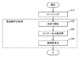
次に、上記のラベルシートの繋ぎ目の特定方法について、図7〜9のフローチャートを参照して説明する。 Next, a method for specifying the seam of the label sheet will be described with reference to the flowcharts of FIGS.
図7は、ラベルシートの繋ぎ目を特定する処理(第一の部分)の一例を示す図である。図8は、ラベルシートの繋ぎ目を特定する処理(第二の部分)の一例を示す図である。図9は、ラベルシートの繋ぎ目を特定する処理(第三の部分)の一例を示す図である。 FIG. 7 is a diagram illustrating an example of a process (first portion) for specifying a joint between label sheets. FIG. 8 is a diagram illustrating an example of a process (second part) for specifying a joint between label sheets. FIG. 9 is a diagram illustrating an example of a process (third portion) for specifying a joint between label sheets.
なお、繋ぎ目を特定する処理においては、印刷ヘッド32による印字、カッター34による切断は、実行されないものとする。
In the process of specifying the joint, printing by the
S10では、コントローラー10は、ラベルシートのローディングを行う。具体的には、コントローラー10は、ユーザーにより挿入されたラベルシートの始端(繋ぎ目が正しく切断された状態の始端)を、紙送りモーター31を回転させて所定の開始位置に固定し、一旦停止する。そして、S20に処理を進める。
In S10, the
S20では、コントローラー10は、紙送りを開始する。具体的には、コントローラー10は、紙送りモーター31を回転させて、ラベルシートの搬送を開始する。そして、処理をS30に進める。
In S20, the
S30では、コントローラー10は、センサー出力値を取得する。具体的には、コントローラー10は、最頻値Jを算出するための所定距離の間、ラベル検出ユニット40からセンサー出力値を取得し、センサー出力値のヒストグラムを生成する。そして、前記所定距離の搬送後、S40に処理を進める。
In S30, the
S40では、コントローラー10は、最頻値を算出する。具体的には、S30で生成したヒストグラムから、センサー出力値の最頻値Jを特定する。そして、処理をS50(図8)に進める。
In S40, the
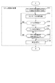
S50では、コントローラー10は、ラベル間検出用の閾値Aとラベル間のシート孔検出用の閾値Hを設定する。具体的には、コントローラー10は、S40で算出した最頻値Jに所定の値αを加算し、ラベル間検出用の閾値Aとして設定する。また、予め定めた値をシート孔検出用の閾値Hとして設定する。そして、処理をS60に進める。
In S50, the
S60では、コントローラー10は、センサー出力値を取得する。具体的には、コントローラー10は、ラベル検出ユニット40からセンサー出力値を得る。そして、処理をS70に進める。なお、S60では、所定の搬送距離ごとの値を得るものとする。
In S60, the
S70では、コントローラー10は、ラベル間を検出したか否かを判定する。具体的には、コントローラー10は、センサー出力値が、上昇する過程で閾値Aと等しくなる走査位置P1A、上昇する過程で閾値Hと等しくなる走査位置P2H、下降する過程で閾値Hと等しくなる走査位置P3H、下降する過程で閾値Aと等しくなる走査位置P4Aを順に特定できたか否かを判定する。4つの走査位置の全てを特定できた場合、又は、P1A及びP4Aのみを特定できた場合、ラベル間を検出したものと判定し(S70:YES)、処理をS80に進める。その他の場合、ラベル間を検出していないと判定し(S70:NO)、処理をS60に戻す。なお、4つの走査位置の全てが特定できていなくても、P2H及びP3Hを特定できた場合に、ラベル間を検出したものと判定してもよい。
In S70, the
S80では、コントローラー10は、シート孔を検出したか否かを判定する。具体的には、コントローラー10は、S70でP2H及びP3Hを特定したか否かを判定する。P2H及びP3Hを特定した場合、シート孔を検出したものと判定し(S80:YES)、処理をS100に進める。P2H及びP3Hを特定していない場合、シート孔を検出していないものと判定し(S80:NO)、処理をS90に進める。
In S80, the
S90では、コントローラー10は、ラベル間の長さが所定距離D以上であるか否かを判定する。具体的には、コントローラー10は、S70で特定したP1AとP4Aの間の距離Lが所定距離D以上であるか否かを判定する。なお、距離Lは、例えば、P1AからP4Aまでのセンサー出力値の数に基づいて特定できる。距離Lが所定距離D以上である場合、ラベル間がスリットではないと判定し(S90:YES)、処理をS100に進める。距離Lが所定距離より小さい場合、ラベル間がスリットであると判定し(S90:NO)、処理をS60に戻す。なお、この場合、コントローラー10は、S70で特定した少なくとも走査位置P1A及びP4Aをリセットし、S60で再びセンサー出力値を取得し始める。
In S90, the
S100では、コントローラー10は、紙送りを停止する。具体的には、コントローラー10は、紙送りモーター31の回転を停止させる。そして、処理をS110(図9)に進める。
In S100, the
S110では、コントローラー10は、シート孔を検出したか否かを判定する。具体的には、コントローラー10は、S80でYESと判定した場合(S110:YES)、処理をS120に進める。S80でNOと判定した場合(S110:NO)、処理をS130に進める。
In S110, the
S120では、コントローラー10は、シート孔の中央位置を特定する。具体的には、コントローラー10は、S70で特定したP2HとP3Hの間の距離Lを2等分した中央位置Tを、ラベルシート間の繋ぎ目位置として特定する。そして、本フローを終了する。
In S120, the
S130では、コントローラー10は、ラベル間の中央位置を特定する。具体的には、コントローラー10は、S70で特定したP1AとP4Aと間の距離Lを2等分した中央位置Tを、ラベルシート間の繋ぎ目位置として特定する。そして、本フローを終了する。
In S130, the
以上のようにして、ラベルシートの繋ぎ目の位置を精度よく特定することができる。なお、コントローラーは、ラベルシートの始端(繋ぎ目が正しく切断された状態の始端)から、特定した繋ぎ目位置(ラベルシートの終端)までを、ラベル一枚分のラベルシート長として特定する。そして、このラベルシート長に基づいて、ラベル一枚分のラベルシートごとにカッター34により切断を行うことができる。 As described above, the position of the joint of the label sheet can be specified with high accuracy. Note that the controller specifies the label sheet length from the start end of the label sheet (start end in a state where the joint is correctly cut) to the specified joint position (end of the label sheet) as one label sheet. And based on this label sheet length, it can cut | disconnect with the cutter 34 for every label sheet for one label.
上述のフローの各処理単位は、ラベルプリンター1の処理を理解容易にするために、主な処理内容に応じて分割したものである。処理単位の分割の仕方や名称によって、本願発明が制限されることはない。ラベルプリンター1の処理は、処理内容に応じて、さらに多くの処理単位に分割することもできる。また、1つの処理単位がさらに多くの処理を含むように分割することもできる。 Each processing unit of the above flow is divided according to main processing contents in order to facilitate understanding of the processing of the label printer 1. The present invention is not limited by the way of dividing the processing unit or the name. The processing of the label printer 1 can be divided into more processing units according to the processing content. Moreover, it can also divide | segment so that one process unit may contain many processes.
以上、本発明の一実施形態の一例について説明した。本実施形態によれば、ラベルプリンターにおいて、ラベルシートの各シートの繋ぎ目を、より精度よく自動で特定することができる。 Heretofore, an example of an embodiment of the present invention has been described. According to this embodiment, in the label printer, the joint of each sheet of the label sheet can be automatically specified with higher accuracy.
例えば、本実施形態では、最頻値を基準とする閾値であって、ラベル間のセンサー出力値が高い部分から十分に離れた低い値である閾値Aが使用される。これにより、ラベル間のセンサー出力値の高い部分で値にばらつきが生じても、位置P1A及び位置P4Aの位置に影響しないため、精度よく繋ぎ目を特定できる。 For example, in the present embodiment, a threshold value A which is a threshold value based on the mode value and which is a low value sufficiently separated from a portion where the sensor output value between labels is high is used. As a result, even if the value varies in the portion where the sensor output value between the labels is high, the position P1A and the position P4A are not affected, and therefore the joint can be identified with high accuracy.
また、例えば、本実施形態では、走査位置P1AとP4Aとの間の距離Lと、所定距離Dとの比較が行われる。これにより、スリットをラベル間と誤認識することをできる限り防き、精度よく繋ぎ目を特定できる。 For example, in this embodiment, the distance L between the scanning positions P1A and P4A is compared with the predetermined distance D. As a result, it is possible to prevent the slits from being erroneously recognized as between the labels as much as possible, and to specify the joints with high accuracy.
<変形例1>
上記の実施形態では、閾値Aは、最頻値Jに所定の値αを加算した値であるため、ラベルシートのセンサー出力値の最頻値と最大値の差が小さくなると、ラベル間を検出できなくなるおそれがある。これに対処するための上記の実施形態の変形例1について、上記の実施形態と異なる点を中心に説明する。
<Modification 1>
In the above embodiment, the threshold value A is a value obtained by adding a predetermined value α to the mode value J. Therefore, when the difference between the mode value and the maximum value of the sensor output value of the label sheet becomes small, the label is detected. There is a risk that it will not be possible. Modification 1 of the above-described embodiment for dealing with this will be described focusing on differences from the above-described embodiment.
図10は、透過率が異なるラベルシートの走査位置とセンサー出力値の関係を説明する図である。本図は、透過率が異なるラベルシート1及び2について、ラベル間とラベル間前後の部分に対応するセンサー出力値を表している。
FIG. 10 is a diagram for explaining the relationship between the scanning position of a label sheet having a different transmittance and the sensor output value. This figure represents sensor output values corresponding to portions between labels and before and after the labels for
ラベルシート2は、例えば、ラベルやシートの材質や厚さなどの要因により、ラベルシート1と比べて透過率が小さいものとする。すると、図示するように、ラベルシート2は、センサー出力値の最頻値と最大値の差分が、ラベルシート1のそれと比べて小さくなる。
The
ここで、ラベルシート2においても、閾値Aを算出するために所定の値αが使用されると、P1AとP4Aとの間の距離Lは、ラベルシート1のそれと比べて短くなる。最頻値と最大値の差分が小さくなるほど、距離Lは、短くなる傾向にある。
Here, also in the
その結果、距離Lが、固定値である距離Dを下回る場合が発生し、この場合、ラベル間がスリットとして判定され、繋ぎ目位置Tが特定されない。 As a result, the distance L may be less than the fixed distance D. In this case, the label is determined as a slit, and the joint position T is not specified.
そこで、変形例1では、図11に示すように、閾値Aとは別に、ラベルシートの透過率の特性に応じた閾値Bを使用する。 Therefore, in the first modification, as shown in FIG. 11, a threshold value B corresponding to the transmittance characteristic of the label sheet is used separately from the threshold value A.
具体的には、コントローラー10は、閾値A及び閾値Hを設定した後、継続してラベルシートを搬送する。そして、センサー出力値が、上昇する過程で閾値Aと等しくなる位置P1A、上昇する過程で閾値Hと等しくなる位置P2H、下降する過程で閾値Hと等しくなる位置P3H、下降する過程で閾値Aと等しくなる位置P4Aの特定を試みる。
Specifically, after setting the threshold value A and the threshold value H, the
ここで、P1A及びP4Aのみを特定できた場合、これらの間のセンサー出力値の最大値Kを特定する。また、式:(最大値K−最頻値J)×所定割合Rによりβを算出し、このβを最頻値Jに加算することで、閾値Bを算出する。このようにして、ラベルシートの特性に応じた閾値Bが算出される。 Here, when only P1A and P4A can be specified, the maximum value K of the sensor output value between them is specified. Further, β is calculated by the formula: (maximum value K−moderate value J) × predetermined ratio R, and the threshold value B is calculated by adding this β to the mode value J. In this way, the threshold value B corresponding to the characteristics of the label sheet is calculated.
閾値Bを設定すると、コントローラー10は、センサー出力値が、上昇する過程で閾値Bと等しくなる位置P1B、下降する過程で閾値Bと等しくなる位置P4Bの特定をする。また、コントローラー10は、ラベル間とスリットの違いを判定するため、走査位置P1BとP4Bとの間の距離Lが、所定距離D以上であるか否かを判定する。
When the threshold value B is set, the
ここで、上記の所定割合Rは、透過率の異なるいずれのラベルシートの距離Lであっても、ラベルシート間で共通に使用される所定距離D以上となるような値である。また、所定距離Dは、透過率の異なるいずれのラベルシートの距離Lも、ラベル間と判定できる値である。 Here, the predetermined ratio R is a value that is equal to or greater than the predetermined distance D that is commonly used between the label sheets, regardless of the distance L between the label sheets having different transmittances. Further, the predetermined distance D is a value at which the distance L between any label sheets having different transmittances can be determined as between labels.
例えば、図12に示すように、透過率が異なるラベルシート1〜3のラベル間の距離が同じであり、センサー出力値の変化を最大値を頂点とする直線で近似できるものとする。この場合、所定割合R=0.5とすると、式:(最大値K−最頻値J)×所定割合Rにより、いずれのラベルシートの距離Lも等しくなる。従って、距離Dを、距離L以下で、かつ、スリットの場合の距離Lよりも大きい値とすれば、透過率が異なるいずれのラベルシートでもラベル間とスリットを判別できる。なお、各種値は、実験的に計測し、統計的に決定した最適値を設定すればよい。 For example, as shown in FIG. 12, the distance between the labels of the label sheets 1 to 3 having different transmittances is the same, and the change in the sensor output value can be approximated by a straight line having the maximum value as the vertex. In this case, if the predetermined ratio R = 0.5, the distance L between all the label sheets becomes equal by the formula: (maximum value K−moderate value J) × predetermined ratio R. Therefore, if the distance D is set to a value equal to or less than the distance L and larger than the distance L in the case of the slit, it is possible to discriminate between the labels and the slits in any label sheet having different transmittance. Various values may be experimentally measured and set to optimum values determined statistically.
また、上記の所定割合Rとして、ラベルシートのセンサー出力値の最頻値(低い側)を基準として発生するばらつきと、ラベル間のセンサー出力値(高い側)の値のばらつきとに影響されにくい値とするのが好ましい。すると、最頻値と最大値の中間である0.5が一応の目安となる。もちろん、この値に限られず、実験を行い、統計的に決定した最適値を採用すればよい。 Further, the predetermined ratio R is not easily affected by variations occurring on the basis of the mode value (lower side) of the sensor output value of the label sheet and variations in sensor output values (higher side) values between labels. A value is preferred. Then, 0.5, which is the middle between the mode value and the maximum value, is a temporary guide. Of course, the present invention is not limited to this value, and an optimum value determined by conducting an experiment and statistically determined may be adopted.
コントローラー10は、走査位置P1BとP4Bとの間の距離Lが所定距離D以上である場合、ラベル間であると判定する。そして、コントローラー10は、走査位置P1BとP4Bとの間の距離Lを2等分した中央位置Tを、ラベル間の中央位置、すなわち、ラベルシート間の繋ぎ目位置として特定する。
When the distance L between the scanning positions P1B and P4B is equal to or greater than the predetermined distance D, the
次に、上記のラベルシートの繋ぎ目の特定方法について、図13のフローチャートを参照して説明する。なお、ラベルシートの繋ぎ目を特定する処理(第一の部分)は、図7と同様である。また、ラベルシートの繋ぎ目を特定する処理(第三の部分)は、図9と同様である。 Next, a method for specifying the seam of the label sheet will be described with reference to the flowchart of FIG. In addition, the process (1st part) which specifies the joint of a label sheet is the same as that of FIG. Further, the process (third part) for specifying the joints of the label sheets is the same as in FIG.
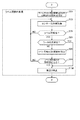
図13は、ラベルシートの繋ぎ目を特定する処理(第二の部分)の変形例を示す図である。 FIG. 13 is a diagram illustrating a modified example of the process (second part) for specifying the joint of the label sheets.
S50〜S80、S90、S100は、図8と基本的に同様なので説明を省略する。なお、S80では、コントローラー10は、シート孔を検出していない場合(S80:NO)、処理をS85に進める。
S50 to S80, S90, and S100 are basically the same as those in FIG. In S80, when the
S85では、コントローラー10は、ラベル間検出用の閾値Bを設定する。具体的には、コントローラー10は、位置P1AからP4Aの間のセンサー出力値の最大値Kを特定する。また、最大値KとS40で算出した最頻値Jとの差分に、所定割合Rを掛けることによりβを算出し、このβを最頻値Jに加算した値を算出し、ラベル間検出用の閾値Bとして設定する。そして、処理をS90に進める。
In S85, the
S90では、コントローラー10は、ラベル間の長さが所定距離D以上であるか否かを判定する。具体的には、コントローラー10は、P1AからP4Aまでの間のセンサー出力値と、S85で設定した閾値Bとに基づいて、走査位置P1B及びP4Bを特定する。それから、走査位置P1BとP4Bとの間の距離Lをラベル間の長さとして算出し、当該距離Lが所定距離D以上であるか否かを判定する。距離Lが所定距離D以上である場合、ラベル間がスリットではないと判定し(S90:YES)、処理をS100に進める。距離Lが所定距離より小さい場合、ラベル間がスリットであると判定し(S90:NO)、処理をS60に戻す。なお、この場合、コントローラー10は、特定した少なくとも走査位置P1A及びP4A、P1B及びP4Bをリセットし、S60で再びセンサー出力値を取得し始める。
In S90, the
なお、S130では、コントローラー10は、S90で特定した走査位置P1BとP4Bとの間の距離Lを2等分した中央位置Tを、ラベルシート間の繋ぎ目位置として特定する。
In S130, the
以上のようにして、透過率が異なるラベルシートであっても、ラベルシートの各シートの繋ぎ目を、より精度よく自動で特定することができる。例えば、本変形例では、ラベルシートの透過率の特性に応じた閾値Bが使用される。これにより、透過率が異なるラベルシートであっても、精度よく繋ぎ目を特定できる。 As described above, even if the label sheets have different transmittances, the joints between the sheets of the label sheet can be automatically specified with higher accuracy. For example, in this modification, a threshold value B corresponding to the transmittance characteristics of the label sheet is used. Thereby, even if it is a label sheet from which the transmittance | permeability differs, a joint can be pinpointed accurately.
また、例えば、本変形例では、透過率が低い側のセンサー出力値のばらつきと、透過率が高い側のセンサー出力値のばらつきの影響を受けにくい高さに閾値Bが設定される。これにより、透過率にばらつきがあるラベルシートであっても、精度よく繋ぎ目を特定できる。 For example, in this modification, the threshold value B is set to a height that is not easily affected by variations in sensor output values on the low transmittance side and sensor output values on the high transmittance side. Thereby, even if it is a label sheet with the dispersion | variation in the transmittance | permeability, a joint can be pinpointed accurately.
<変形例2>
ところで、ラベルシートとして、RFIDに使用される領域を有するものが想定される。この領域には、例えば、識別情報を記憶する半導体素子や、前記識別情報を外部と送受信するアンテナなどが設けられている。従って、この領域をセンサー出力値の最頻値を決定するのに使用するのは適当でない。そこで、変形例2に係るラベルプリンター1は、RFID領域のセンサー出力値を使用しないように動作する。上記の実施形態と異なる点を中心に説明する。
<
By the way, what has the area | region used for RFID as a label sheet is assumed. In this area, for example, a semiconductor element that stores identification information, an antenna that transmits and receives the identification information to the outside, and the like are provided. Therefore, it is not appropriate to use this area to determine the mode value of the sensor output value. Therefore, the label printer 1 according to the modified example 2 operates so as not to use the sensor output value in the RFID area. A description will be given centering on differences from the above embodiment.
図14は、RFID領域を有するラベルシートの例を示す図である。 FIG. 14 is a diagram illustrating an example of a label sheet having an RFID area.
本図に示すように、ラベルシート(D)は、ラベルの中央より前側(搬送方向側)にRFID領域を備える。図示していないが、RFID領域には、半導体素子やアンテナが配置されている。ここで、RFID領域の大きさやラベル上の配置は、規格上予め決められているものとする。もちろん、上記のラベルシートの仕様は、例示であり、RFID領域の形状、位置、大きさ等は上記に限られない。 As shown in the figure, the label sheet (D) includes an RFID area on the front side (conveyance direction side) from the center of the label. Although not shown, semiconductor elements and antennas are arranged in the RFID region. Here, it is assumed that the size of the RFID area and the arrangement on the label are determined in advance according to the standard. Of course, the specifications of the label sheet are examples, and the shape, position, size, and the like of the RFID area are not limited to the above.
コントローラー10は、紙送りを開始した後、RFID領域を含む所定距離の間、センサー出力値の取得を行わない。そして、前記所定距離以外の位置で取得したセンサー出力値を使用する。
The
次に、上記のラベルシートの繋ぎ目の特定方法について、図15のフローチャートを参照して説明する。なお、ラベルシートの繋ぎ目を特定する処理(第二の部分)は、図8と同様である。また、ラベルシートの繋ぎ目を特定する処理(第三の部分)は、図9と同様である。 Next, a method for specifying the seam of the label sheet will be described with reference to the flowchart of FIG. In addition, the process (2nd part) which specifies the joint of a label sheet is the same as that of FIG. Further, the process (third part) for specifying the joints of the label sheets is the same as in FIG.
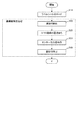
図15は、ラベルシートの繋ぎ目を特定する処理(第一の部分)の変形例を示す図である。 FIG. 15 is a diagram illustrating a modified example of the process (first portion) for specifying the joint of the label sheets.
S10、S20、S30、S40は、図7と基本的に同様なので説明を省略する。なお、S20では、コントローラー10は、紙送りを開始して、処理をS25に進める。
S10, S20, S30, and S40 are basically the same as those in FIG. In S20, the
S25では、コントローラー10は、RFID領域の通過を待つ。具体的には、コントローラー10は、RFID領域を含む所定距離の間、ラベル検出ユニット40からのセンサー出力値を読み捨てる。前記所定距離の通過後、処理をS30に進める。なお、前記所定距離の間、コントローラー10は、ラベル検出ユニット40の読み取り動作を停止するようにしてもよい。
In S25, the
以上のようにして、RFID領域を備えるラベルシートであっても、繋ぎ目の位置を精度よく特定することができる。もちろん、変形例2は、変形例1と組み合わせてもよい。 As described above, even with a label sheet having an RFID area, the position of the joint can be accurately identified. Of course, the second modification may be combined with the first modification.
<変形例3>
ラベルシートとして、ラベル間と同程度の幅の特殊なスリットを有するものも想定される。この場合、所定距離Dを用いた判定を行っても、スリットを誤ってラベル間と認識するおそれがある。そこで、変形例3に係るラベルプリンター1は、ラベルシートを搬送中に一度ラベル間を検出した後も、判定を継続する。上記の実施形態と異なる点を中心に説明する。
<
A label sheet having a special slit having the same width as that between labels is also assumed. In this case, even if the determination using the predetermined distance D is performed, the slit may be erroneously recognized as between the labels. Therefore, the label printer 1 according to the modified example 3 continues the determination even after detecting between the labels once during the conveyance of the label sheet. A description will be given centering on differences from the above embodiment.
図16は、特殊スリットを有するラベルシートの例を示す図である。 FIG. 16 is a diagram illustrating an example of a label sheet having a special slit.
本図に示すように、ラベルシート(E)は、ラベルの中央より後側(搬送方向と反対側)に特殊スリットを備える。特殊スリットは、ラベル間のように矩形状の領域ではなく、曲線状の領域となっている。そして、その幅は、ラベル間の幅に近い。ここで、規格上、特殊スリットを有するラベルシートのラベル間には、シート孔が設けられているものとする。また、規格上、特殊スリットの位置は、ラベル間から所定距離以内と定められているものとする。もちろん、上記のラベルシートの仕様は、例示であり、特殊スリットの形状、位置、大きさ等は上記に限られない。 As shown in the figure, the label sheet (E) is provided with a special slit on the rear side (opposite to the conveying direction) from the center of the label. The special slit is not a rectangular area like between labels, but a curved area. The width is close to the width between labels. Here, it is assumed that a sheet hole is provided between the labels of the label sheet having the special slit in terms of the standard. Further, according to the standard, the position of the special slit is determined to be within a predetermined distance from between the labels. Of course, the specifications of the label sheet are examples, and the shape, position, size, and the like of the special slit are not limited to the above.
コントローラー10は、ラベル間を一度検出した後も紙送りを継続し、シート孔を検出したか否かを判定する。シート孔が検出された場合は、該シート孔の中央を繋ぎ目位置として特定する。一方、ラベル間を一度検出した後、シート孔が検出されず、かつ、所定距離の紙送りが終了した場合は、一度目に検出されたラベル間の中央を繋ぎ目位置として特定する。ここで、前記所定距離は、例えば、特殊スリットを有する各種仕様のラベルシートのうち、特殊スリットからラベル間を含む位置までの最大の距離とすることができる。
The
次に、上記のラベルシートの繋ぎ目の特定方法について、図17のフローチャートを参照して説明する。なお、ラベルシートの繋ぎ目を特定する処理(第一の部分)は、図7と同様である。また、ラベルシートの繋ぎ目を特定する処理(第三の部分)は、図9と同様である。 Next, a method for specifying the seam of the label sheet will be described with reference to the flowchart of FIG. In addition, the process (1st part) which specifies the joint of a label sheet is the same as that of FIG. Further, the process (third part) for specifying the joints of the label sheets is the same as in FIG.
図17は、ラベルシートの繋ぎ目を特定する処理(第二の部分)の他の変形例を示す図である。 FIG. 17 is a diagram illustrating another modified example of the process (second part) for specifying the joint of the label sheets.
S50〜S90、S100は、図8と基本的に同様なので説明を省略する。なお、S90では、コントローラー10は、距離Lが所定距離D以上である場合(S90:YES)、処理をS92に進める。
S50 to S90 and S100 are basically the same as those in FIG. In S90,
S92では、コントローラー10は、所定距離の紙送りが終了したか否かを判定する。具体的には、コントローラー10は、S90でYESと判定されてからの搬送距離が、特殊スリットからラベル間を含む位置までの所定距離を超えたか否かを判定する。所定距離の紙送りが終了していない場合(S92:NO)、処理をS94に進める。所定距離の紙送りが終了した場合(S92:YES)、処理をS100に進める。
In S92, the
S94では、コントローラー10は、センサー出力値を取得する。具体的には、コントローラー10は、ラベル検出ユニット40からセンサー出力値を得る。そして、処理をS96に進める。なお、S96では、所定の搬送距離ごとの値を得るものとする。
In S94, the
S96では、コントローラー10は、ラベル間を検出したか否かを判定する。具体的には、コントローラー10は、センサー出力値が、上昇する過程で閾値Aと等しくなる走査位置P1A、上昇する過程で閾値Hと等しくなる走査位置P2H、下降する過程で閾値Hと等しくなる走査位置P3H、下降する過程で閾値Aと等しくなる走査位置P4Aを順に特定できたか否かを判定する。4つの走査位置の全てを特定できた場合、又は、P1A及びP4Aのみを特定できた場合、ラベル間を検出したものと判定し(S96:YES)、処理をS98に進める。その他の場合、ラベル間を検出していないと判定し(S96:NO)、処理をS92に戻す。
In S96, the
S98では、コントローラー10は、シート孔を検出したか否かを判定する。具体的には、コントローラー10は、S96でP2H及びP3Hを特定したか否かを判定する。P2H及びP3Hを特定した場合、シート孔を検出したものと判定し(S98:YES)、処理をS100に進める。P2H及びP3Hを特定していない場合、シート孔を検出していないものと判定し(S98:NO)、処理をS92に戻す。
In S98, the
なお、S110では、コントローラー10は、S80又はS98でYESと判定した場合(S110:YES)、処理をS120に進める。S92でYESと判定した場合(S110:NO)、処理をS130に進める。そして、S120では、コントローラー10は、S70又はS96で特定したP2HとP3Hとの間の距離Lを2等分した中央位置Tを、ラベルシート間の繋ぎ目位置として特定する。一方、S130では、コントローラー10は、S70で特定した走査位置P1AとP4Aとの間の距離Lを2等分した中央位置Tを、ラベルシート間の繋ぎ目位置として特定する。
In S110, when the
以上のようにして、特殊スリットを備えるラベルシートであっても、ラベルシートの各シートの繋ぎ目を、より精度よく自動で特定することができる。もちろん、変形例3は、変形例1や変形例2と組み合わせてもよい。
As described above, even in the case of a label sheet having a special slit, the joint of each sheet of the label sheet can be automatically specified with higher accuracy. Of course,
<変形例4>
以上の実施形態及び変形例では、コントローラー10は、受光素子40aが受光素子を複数備える場合、予め選択したいずれか一つの受光素子の出力を使用しているが、条件に応じて使用する受光素子を選択してもよい。
<
In the above embodiments and modifications, the
例えば、コントローラー10は、複数の受光素子それぞれについて、S30〜70(図7〜9参照)の処理を実行し、最初に(すなわち、最も早い時間に)走査位置P1に該当するセンサー出力値を得られた受光素子を、その後の処理に使用する受光素子として選択する。そして、選択していない受光素子については、コントローラーは、例えば、出力値を読み捨てたり、当該受光素子の動作を停止したりすればよい。また、選択していない受光素子に対応する発光素子の発光を停止するようにしてもよい。
For example, the
また、例えば、コントローラー10は、複数の受光素子それぞれについて、S30〜70(図7〜9参照)の処理を実行し、最初に、4つの走査位置の全て、又はP1A及びP4A、又はP2H及びP3Hに該当するセンサー出力値を得られた受光素子を、その後の処理に使用する受光素子として選択する。また、最初に、S80でYESと判定することができた受光素子、又はS90でYESと判定することができた受光素子を、その後の処理に使用する受光素子として選択してもよい。そして、選択していない受光素子については、コントローラーは、例えば、出力値を読み捨てたり、当該受光素子の動作を停止したりすればよい。また、選択していない受光素子に対応する発光素子の発光を停止するようにしてもよい。
In addition, for example, the
<変形例5>
複数の受光素子のセンサー出力値を用いて、ラベル間の形状を特定するようにしてもよい。
<
The shape between labels may be specified using sensor output values of a plurality of light receiving elements.
例えば、コントローラー10は、受光素子ごとに、走査位置P1及びP4を特定する。そして、各素子における走査位置P1及びP4の位置や距離Lの長さなどの関係に基づいて、ラベル間の形状を特定する。例えば、ラベル間の形状が搬送方向と直交する矩形なのか否かを判定する。そして、矩形でなければ、スリットであると判定することができる。
For example, the
また、例えば、コントローラー10は、受光素子ごとに、走査位置P2及びP3を特定し、各素子における走査位置P2及びP3の位置や距離Lの長さなどの関係に基づいて、シート孔の位置、シート孔の形状、シート孔の数などを特定するようにしてもよい。
Further, for example, the
上記の本発明の実施形態及び変形例は、本発明の要旨と範囲を例示することを意図し、限定するものではない。多くの代替物、修正および変形例が当業者にとって明らかである。上記の実施形態及び変形例は、一以上を組み合わせてもよい。 The above-described embodiments and modifications of the present invention are intended to illustrate the spirit and scope of the present invention and are not intended to be limiting. Many alternatives, modifications, and variations will be apparent to those skilled in the art. One or more of the above embodiments and modifications may be combined.
なお、本発明は、透過センサーに限らず、反射センサーなどの他のセンサーであっても適用できる。 The present invention is not limited to the transmission sensor, and can be applied to other sensors such as a reflection sensor.
また、本実施形態のラベルプリンターは、ラベル一枚分のラベルシートの長さを算出した後は、そのロールが交換されるまで、算出した長さの搬送を行うごとにラベルシートをカットする。又は、第一のシート位置若しくは第二のシート位置からシートの繋ぎ目位置までの距離を記憶しておき、第一のシート位置若しくは第二のシート位置が特定された後、前記繋ぎ目位置までの距離を搬送してラベルシートをカットするようにしてもよい。もちろん、ラベルごとにシートの繋ぎ目位置を特定してカットするようにしてもよい。 Moreover, after calculating the length of the label sheet for one label, the label printer of this embodiment cuts the label sheet every time the calculated length is conveyed until the roll is replaced. Or, the distance from the first sheet position or the second sheet position to the joint position of the sheet is stored, and after the first sheet position or the second sheet position is specified, to the joint position This distance may be conveyed to cut the label sheet. Of course, the sheet joint position may be specified and cut for each label.
1:ラベルプリンター、10:コントローラー、20:操作パネル、30:印刷ユニット、31:紙送りモーター、32:印刷ヘッド、33:プラテンローラー、34:カッター、34a:上刃、34b:下刃、40:ラベル検出ユニット、40a:受光素子、40b:発光素子 1: label printer, 10: controller, 20: operation panel, 30: printing unit, 31: paper feed motor, 32: print head, 33: platen roller, 34: cutter, 34a: upper blade, 34b: lower blade, 40 : Label detection unit, 40a: Light receiving element, 40b: Light emitting element
Claims (8)
センサー出力値の最頻値を特定する最頻値特定手段と、
前記ラベルシートの搬送方向で、前記最頻値に応じて決定したラベル間のシート部分を検出する前記センサー出力値が第一の閾値を超える第一のシート位置と、前記センサー出力値が前記第一の閾値よりも大きい値であって前記ラベルシートの孔を検出する前記センサー出力値が第二の閾値を超える第二のシート位置と、前記センサー出力値が前記第二の閾値を下回る第三のシート位置と、前記センサー出力値が前記第一の閾値を下回る第四のシート位置と、を特定するシート位置特定手段と、
前記第一のシート位置及び前記第四のシート位置が特定されて前記第二のシート位置及び前記第三のシート位置が特定されていない場合、前記第一のシート位置から前記第四のシート位置までの第一区間の中央をラベル間のシートの繋ぎ目位置として特定し、
前記第一のシート位置及び前記第四のシート位置が特定されて前記第二のシート位置及び前記第三のシート位置が特定されている場合、前記第二のシート位置から前記第三のシート位置までの第二区間の中央をラベル間のシートの繋ぎ目位置として特定する繋ぎ目位置特定手段と、
を有することを特徴とするラベル搬送装置。 A sensor that reads a label sheet in which a plurality of labels are arranged on the sheet and outputs a sensor output value;
A mode value specifying means for specifying the mode value of the sensor output value;
The conveying direction of the label sheet, the mode value and a first seat position the sensor output value to detect the sheet portion is in excess of the first threshold value between the determined label in accordance with, the sensor output value is the under a second seat position the sensor output value to detect the hole of the label sheet is in excess of a second threshold value to a value larger than the first threshold value, the sensor output value is the second threshold value a third sheet position Ru times, and the sheet position specifying means for the sensor output value is identified and a fourth sheet position that falls below the first threshold value,
When the first sheet position and the fourth sheet position are specified and the second sheet position and the third sheet position are not specified, the fourth sheet position is determined from the first sheet position. Specify the center of the first section until the sheet joint position between the labels,
When the first sheet position and the fourth sheet position are specified and the second sheet position and the third sheet position are specified, the second sheet position to the third sheet position A joint position specifying means for specifying the center of the second section up to the sheet joint position between the labels;
A label carrying device comprising:
前記シート位置特定手段は、所定区間よりも搬送方向後方の区間のセンサー出力値を用いて前記各シート位置を特定する請求項1ないし6のいずれか1項に記載のラベル搬送装置。 The mode value specifying means specifies the mode value using a sensor output value of a first predetermined section after the start of conveyance of the label sheet,
The seat position specifying means, the label transport device according to any one of claims 1 to 6 for identifying the respective seat position using the sensor output value in the conveying direction behind the section than Jo Tokoro interval.
前記ラベルシートを読み取ってセンサー出力値を出力し、
前記センサー出力値の最頻値を特定し、
前記ラベルシートの搬送方向で、前記最頻値に応じて決定したラベル間のシート部分を検出する前記センサー出力値が第一の閾値を超える第一のシート位置を特定し、
前記ラベルシートの搬送方向で、前記センサー出力値が前記第一の閾値よりも大きい値であって前記ラベルシートの孔を検出する前記センサー出力値が第二の閾値を超える第二のシート位置を特定し、
前記ラベルシートの搬送方向で、前記センサー出力値が前記第二の閾値を下回る第三のシート位置を特定し、
前記ラベルシートの搬送方向で、前記センサー出力値が前記第一の閾値を下回る第四のシート位置を特定し、
前記第四のシート位置が特定された際に、前記第二のシート位置及び前記第三のシート位置が特定されていない場合、前記第一のシート位置から前記第四のシート位置までの第一区間の中央をラベル間のシートの繋ぎ目位置として特定し、
前記第四のシート位置が特定された際に、前記第二のシート位置及び前記第三のシート位置が特定されている場合、前記第二のシート位置から前記第三のシート位置までの第二区間の中央をラベル間のシートの繋ぎ目位置として特定することを特徴とする繋ぎ目特定方法。 Conveys a label sheet in which multiple labels are arranged on the sheet,
Read the label sheet and output the sensor output value,
Identify the mode value of the sensor output value,
Wherein the conveying direction of the label sheet to identify the first seat position the sensor output value to detect the sheet portion is in excess of the first threshold between the label determined according to the mode value,
Wherein the conveying direction of the label sheet, the sensor output value is a second seat position the sensor output value detected by the in excess of a second threshold a hole of the first of the label sheet to a value greater than the threshold value Identify
The conveying direction of the label sheet to identify the third sheet position the sensor output value that falls below the second threshold value,
The conveying direction of the label sheet to identify the fourth sheet position the sensor output value that falls below the first threshold value,
If the second sheet position and the third sheet position are not specified when the fourth sheet position is specified, the first sheet position to the fourth sheet position is not specified. Specify the center of the section as the joint position of the sheet between labels,
When the second sheet position and the third sheet position are specified when the fourth sheet position is specified, the second sheet position from the second sheet position to the third sheet position is specified. A joint identification method characterized by identifying a center of a section as a joint position of a sheet between labels.
Priority Applications (2)
| Application Number | Priority Date | Filing Date | Title |
|---|---|---|---|
| JP2011160722A JP5747710B2 (en) | 2011-07-22 | 2011-07-22 | Label conveying apparatus and label sheet joint specifying method |
| US13/220,515 US8573869B2 (en) | 2011-07-22 | 2011-08-29 | Label sheet conveyance device and method of identifying seams between label sheets |
Applications Claiming Priority (1)
| Application Number | Priority Date | Filing Date | Title |
|---|---|---|---|
| JP2011160722A JP5747710B2 (en) | 2011-07-22 | 2011-07-22 | Label conveying apparatus and label sheet joint specifying method |
Publications (3)
| Publication Number | Publication Date |
|---|---|
| JP2013022861A JP2013022861A (en) | 2013-02-04 |
| JP2013022861A5 JP2013022861A5 (en) | 2014-06-26 |
| JP5747710B2 true JP5747710B2 (en) | 2015-07-15 |
Family
ID=47555249
Family Applications (1)
| Application Number | Title | Priority Date | Filing Date |
|---|---|---|---|
| JP2011160722A Expired - Fee Related JP5747710B2 (en) | 2011-07-22 | 2011-07-22 | Label conveying apparatus and label sheet joint specifying method |
Country Status (2)
| Country | Link |
|---|---|
| US (1) | US8573869B2 (en) |
| JP (1) | JP5747710B2 (en) |
Families Citing this family (6)
| Publication number | Priority date | Publication date | Assignee | Title |
|---|---|---|---|---|
| US9024988B2 (en) * | 2011-12-22 | 2015-05-05 | Datamax-O'neil Corporation | Media detection apparatus and method |
| CN104275948B (en) | 2013-07-04 | 2017-07-28 | 精工爱普生株式会社 | The alignment method of printing equipment, print head and printing equipment |
| JP6210285B2 (en) * | 2013-09-20 | 2017-10-11 | セイコーエプソン株式会社 | Recording medium detection device, image recording device |
| JP6083395B2 (en) * | 2014-02-07 | 2017-02-22 | コニカミノルタ株式会社 | Image forming apparatus and image forming method |
| JP6513006B2 (en) * | 2015-09-30 | 2019-05-15 | 株式会社マキタ | Motor control device |
| WO2020067869A1 (en) * | 2018-09-25 | 2020-04-02 | Ccs Innovation Holding Sdn Bhd | Optical imaging labelling printer |
Family Cites Families (7)
| Publication number | Priority date | Publication date | Assignee | Title |
|---|---|---|---|---|
| JPS5720363Y2 (en) * | 1974-06-29 | 1982-04-30 | ||
| JP2501464B2 (en) | 1988-11-14 | 1996-05-29 | 株式会社テック | Label printer |
| JP2959961B2 (en) * | 1994-06-28 | 1999-10-06 | 東芝テック株式会社 | Printer |
| JP4149867B2 (en) * | 2003-07-28 | 2008-09-17 | キヤノンファインテック株式会社 | Printer and its control method |
| JP5386881B2 (en) * | 2008-08-07 | 2014-01-15 | セイコーエプソン株式会社 | Label paper cueing control method and label printer |
| JP2011011389A (en) * | 2009-06-30 | 2011-01-20 | Sato Knowledge & Intellectual Property Institute | Thermal printer and label-paper detecting method for the same |
| JP4965619B2 (en) * | 2009-09-16 | 2012-07-04 | 東芝テック株式会社 | Printer, program, and printing start position determination method |
-
2011
- 2011-07-22 JP JP2011160722A patent/JP5747710B2/en not_active Expired - Fee Related
- 2011-08-29 US US13/220,515 patent/US8573869B2/en not_active Expired - Fee Related
Also Published As
| Publication number | Publication date |
|---|---|
| US8573869B2 (en) | 2013-11-05 |
| US20130020758A1 (en) | 2013-01-24 |
| JP2013022861A (en) | 2013-02-04 |
Similar Documents
| Publication | Publication Date | Title |
|---|---|---|
| JP5747710B2 (en) | Label conveying apparatus and label sheet joint specifying method | |
| US9656486B2 (en) | Printer and printing system | |
| CN106985558B (en) | Printing apparatus and printing method | |
| US20180250959A1 (en) | Non-Transitory Storage Medium Storing Program Readable by Label Printer or Operation Terminal, Label Creating Method, and the Label Printer | |
| US9672457B2 (en) | Image forming apparatus capable of changing cut position on long medium and control method thereof | |
| US8736872B2 (en) | Image forming system and print instruction terminal | |
| EP2832547B1 (en) | Print tape and tape printer | |
| US10744789B2 (en) | Printing device, printing method, and nonvolatile computer-readable recording medium | |
| CN110315873A (en) | Printing equipment | |
| JP2010202307A (en) | Method for detecting recording paper and printer | |
| US20180251252A1 (en) | Label Creating Apparatus, Non-Transitory Storage Medium Storing Program Readable by the Label Creating Apparatus, and Method of Label Cutting Processing Performed by the Label Creating Apparatus | |
| EP3851287A1 (en) | Label printer and label printer control method | |
| US10828919B2 (en) | Printer and method for accurately recognizing positions of labels | |
| JP6910129B2 (en) | Printer | |
| EP2085237A1 (en) | Image forming device, transporting control method, and computer-readable recording medium | |
| CN111689263A (en) | Printer with a movable platen | |
| EP3697072B1 (en) | Sheet feeding apparatus, information processing method, and program | |
| US20110215130A1 (en) | Sheet handling apparatus and sheet collecting method | |
| US11827042B2 (en) | Tag writing device, label printer, and information processing program | |
| JP6274933B2 (en) | Printer | |
| JP2019177584A (en) | Printing apparatus and method for controlling printing apparatus | |
| US11753268B2 (en) | Finishing system, piercing member abnormality determination device, and recording medium | |
| JP6059547B2 (en) | Printing device | |
| JP5481449B2 (en) | Printing apparatus and control program therefor | |
| JP6160344B2 (en) | Printing tape and tape printer |
Legal Events
| Date | Code | Title | Description |
|---|---|---|---|
| A521 | Written amendment |
Free format text: JAPANESE INTERMEDIATE CODE: A523 Effective date: 20140512 |
|
| A621 | Written request for application examination |
Free format text: JAPANESE INTERMEDIATE CODE: A621 Effective date: 20140512 |
|
| RD04 | Notification of resignation of power of attorney |
Free format text: JAPANESE INTERMEDIATE CODE: A7424 Effective date: 20150107 |
|
| A977 | Report on retrieval |
Free format text: JAPANESE INTERMEDIATE CODE: A971007 Effective date: 20150206 |
|
| A131 | Notification of reasons for refusal |
Free format text: JAPANESE INTERMEDIATE CODE: A131 Effective date: 20150217 |
|
| A521 | Written amendment |
Free format text: JAPANESE INTERMEDIATE CODE: A523 Effective date: 20150320 |
|
| TRDD | Decision of grant or rejection written | ||
| A01 | Written decision to grant a patent or to grant a registration (utility model) |
Free format text: JAPANESE INTERMEDIATE CODE: A01 Effective date: 20150414 |
|
| A61 | First payment of annual fees (during grant procedure) |
Free format text: JAPANESE INTERMEDIATE CODE: A61 Effective date: 20150427 |
|
| R150 | Certificate of patent or registration of utility model |
Ref document number: 5747710 Country of ref document: JP Free format text: JAPANESE INTERMEDIATE CODE: R150 |
|
| S531 | Written request for registration of change of domicile |
Free format text: JAPANESE INTERMEDIATE CODE: R313531 |
|
| R350 | Written notification of registration of transfer |
Free format text: JAPANESE INTERMEDIATE CODE: R350 |
|
| LAPS | Cancellation because of no payment of annual fees |