JP5747417B2 - Game machine - Google Patents
Game machine Download PDFInfo
- Publication number
- JP5747417B2 JP5747417B2 JP2012116020A JP2012116020A JP5747417B2 JP 5747417 B2 JP5747417 B2 JP 5747417B2 JP 2012116020 A JP2012116020 A JP 2012116020A JP 2012116020 A JP2012116020 A JP 2012116020A JP 5747417 B2 JP5747417 B2 JP 5747417B2
- Authority
- JP
- Japan
- Prior art keywords
- effect
- display
- variation
- big hit
- variation pattern
- Prior art date
- Legal status (The legal status is an assumption and is not a legal conclusion. Google has not performed a legal analysis and makes no representation as to the accuracy of the status listed.)
- Active
Links
- 230000000694 effects Effects 0.000 claims description 809
- 230000015654 memory Effects 0.000 claims description 136
- 239000000725 suspension Substances 0.000 claims description 2
- 238000000034 method Methods 0.000 description 411
- 230000008569 process Effects 0.000 description 409
- 238000003860 storage Methods 0.000 description 168
- 230000002844 continuous effect Effects 0.000 description 137
- 230000000875 corresponding effect Effects 0.000 description 132
- 238000004519 manufacturing process Methods 0.000 description 104
- 230000008859 change Effects 0.000 description 103
- 239000000872 buffer Substances 0.000 description 95
- 238000012545 processing Methods 0.000 description 54
- 238000010924 continuous production Methods 0.000 description 43
- 238000010586 diagram Methods 0.000 description 25
- 239000012536 storage buffer Substances 0.000 description 23
- 230000014759 maintenance of location Effects 0.000 description 20
- 230000001276 controlling effect Effects 0.000 description 18
- 238000013461 design Methods 0.000 description 17
- 230000009467 reduction Effects 0.000 description 17
- 238000001514 detection method Methods 0.000 description 15
- 238000005034 decoration Methods 0.000 description 12
- 238000004904 shortening Methods 0.000 description 10
- 241000167854 Bourreria succulenta Species 0.000 description 9
- 238000004458 analytical method Methods 0.000 description 9
- 230000005540 biological transmission Effects 0.000 description 9
- 235000019693 cherries Nutrition 0.000 description 9
- 238000012790 confirmation Methods 0.000 description 9
- 230000006870 function Effects 0.000 description 9
- 230000004048 modification Effects 0.000 description 8
- 238000012986 modification Methods 0.000 description 8
- 238000009877 rendering Methods 0.000 description 8
- 230000004044 response Effects 0.000 description 8
- 238000011084 recovery Methods 0.000 description 7
- 230000007704 transition Effects 0.000 description 7
- FPIPGXGPPPQFEQ-OVSJKPMPSA-N all-trans-retinol Chemical compound OC\C=C(/C)\C=C\C=C(/C)\C=C\C1=C(C)CCCC1(C)C FPIPGXGPPPQFEQ-OVSJKPMPSA-N 0.000 description 6
- OMFRMAHOUUJSGP-IRHGGOMRSA-N bifenthrin Chemical compound C1=CC=C(C=2C=CC=CC=2)C(C)=C1COC(=O)[C@@H]1[C@H](\C=C(/Cl)C(F)(F)F)C1(C)C OMFRMAHOUUJSGP-IRHGGOMRSA-N 0.000 description 6
- 230000001360 synchronised effect Effects 0.000 description 6
- 238000003825 pressing Methods 0.000 description 5
- 239000000758 substrate Substances 0.000 description 5
- 239000000284 extract Substances 0.000 description 4
- 238000007781 pre-processing Methods 0.000 description 4
- 235000019169 all-trans-retinol Nutrition 0.000 description 3
- 239000011717 all-trans-retinol Substances 0.000 description 3
- 230000015572 biosynthetic process Effects 0.000 description 3
- 239000011521 glass Substances 0.000 description 3
- 238000012544 monitoring process Methods 0.000 description 3
- 238000003786 synthesis reaction Methods 0.000 description 3
- 230000004913 activation Effects 0.000 description 2
- 238000007792 addition Methods 0.000 description 2
- 230000004397 blinking Effects 0.000 description 2
- 230000007423 decrease Effects 0.000 description 2
- 230000003247 decreasing effect Effects 0.000 description 2
- 238000006073 displacement reaction Methods 0.000 description 2
- 230000007246 mechanism Effects 0.000 description 2
- 230000001105 regulatory effect Effects 0.000 description 2
- 230000008685 targeting Effects 0.000 description 2
- 238000004364 calculation method Methods 0.000 description 1
- 239000003990 capacitor Substances 0.000 description 1
- 239000003086 colorant Substances 0.000 description 1
- 238000012938 design process Methods 0.000 description 1
- 238000000605 extraction Methods 0.000 description 1
- 238000010304 firing Methods 0.000 description 1
- 230000001788 irregular Effects 0.000 description 1
- 239000004973 liquid crystal related substance Substances 0.000 description 1
- 239000000463 material Substances 0.000 description 1
- 230000001151 other effect Effects 0.000 description 1
- 230000002093 peripheral effect Effects 0.000 description 1
- 238000002203 pretreatment Methods 0.000 description 1
- 239000011347 resin Substances 0.000 description 1
- 229920005989 resin Polymers 0.000 description 1
- 230000000717 retained effect Effects 0.000 description 1
- 230000005236 sound signal Effects 0.000 description 1
- 230000002194 synthesizing effect Effects 0.000 description 1
- 238000012546 transfer Methods 0.000 description 1
Images


Landscapes
- Display Devices Of Pinball Game Machines (AREA)
Description
本発明は、所定の始動条件が成立したことに基づいて、各々を識別可能な複数種類の識別情報の可変表示を行い表示結果を導出表示する可変表示手段に予め定められた特定表示結果が導出されたときに、遊技者にとって有利な特定遊技状態に制御する遊技機に関する。 The present invention derives a specific display result predetermined for variable display means for variably displaying a plurality of types of identification information that can be distinguished from each other and deriving and displaying the display result based on the establishment of a predetermined starting condition. The present invention relates to a gaming machine that controls to a specific gaming state advantageous to a player when played.
遊技機として、遊技媒体である遊技球を発射装置によって遊技領域に発射し、遊技領域に設けられている入賞口などの入賞領域に遊技球が入賞すると、所定個の賞球が遊技者に払い出されるものがある。さらに、識別情報を可変表示(「変動」ともいう。)可能な可変表示部が設けられ、可変表示部において識別情報の可変表示の表示結果が特定表示結果となった場合に、所定の遊技価値を遊技者に与えるように構成されたものがある。 As a gaming machine, a game ball, which is a game medium, is launched into a game area by a launching device, and when a game ball wins a prize area such as a prize opening provided in the game area, a predetermined number of prize balls are paid out to the player. There is something to be done. Further, a variable display unit capable of variably displaying the identification information (also referred to as “fluctuation”) is provided, and a predetermined game value is obtained when the display result of the variable display of the identification information in the variable display unit becomes a specific display result. Are configured to give the player.
この種の遊技機として、可変表示装置において識別情報の可変表示を実行する権利を所定の上限数まで保留情報として記憶するとともに、その保留情報に対応した可変表示が実行されるより前に当該保留情報に対応した表示結果を先読みして、予告演出(先読み予告演出)を実行するものが提案されている。 As this type of gaming machine, the right to execute variable display of identification information in a variable display device is stored as hold information up to a predetermined upper limit number, and the hold before the variable display corresponding to the hold information is executed. Proposals have been made to pre-read display results corresponding to information and execute a notice effect (pre-read notice effect).
この種の先読み演出として、記憶している保留記憶数を表示する保留記憶表示領域の表示態様を先読み結果に応じて所定の保留絵柄に変化させるとともに、変動時においてリーチに移行しない場合には、記憶表示位置から飛んできた保留絵柄はその場で消える一方、リーチに移行する場合には、記憶表示位置から飛んできた保留絵柄はその場に残りリーチの演出をアシストするといったものがあった(例えば、特許文献1参照)。 As this type of pre-reading effect, the display mode of the reserved storage display area that displays the stored number of reserved memories is changed to a predetermined reserved pattern according to the result of pre-reading, and when the transition does not shift to reach, While the reserved picture that flew from the memory display position disappears on the spot, in the case of shifting to reach, the reserved picture that flew from the memory display position remained on the spot and assisted the production of reach (there was For example, see Patent Document 1).
また、はずれの変動において出現したキャラクタをストックしておき、特定のリーチ演出においてストックされていたキャラクタを登場させるようにしたもの等があった(例えば、特許文献2参照)。 In addition, there are those in which characters that have appeared in the fluctuation of deviation are stocked and characters that have been stocked in a specific reach production are made to appear (for example, see Patent Document 2).
上記特許文献1に記載の遊技機では、変動開始時において飛んできた保留絵柄が消えるか否かの演出によってリーチ演出が実行されるか否かが示唆されるだけであるため、演出が単調となるばかりか、遊技者のリーチ演出の実行に対する期待感だけしか向上させることができずという問題があった。
In the gaming machine described in the above-mentioned
また、上記特許文献2に記載の遊技機では、ストックされたキャラクタは特定のリーチが実行される場合にのみ出現する、すなわち、ストックされたキャラクタの出現率は特定のリーチの出現率に依存してしまうため、遊技の興趣が低減する虞があった。
In addition, in the gaming machine described in
本発明は、このような問題点に着目してなされたもので、判定の対象となった変動にて実行される演出に対する期待感を向上させることができる遊技機を提供することを目的とする。 The present invention has been made paying attention to such problems, and an object of the present invention is to provide a gaming machine capable of improving a sense of expectation with respect to an effect executed in accordance with a variation that has been determined. .
前記課題を解決するために、本発明の遊技機は、
識別情報(特別図柄、飾り図柄)の可変表示を行って表示結果を導出する可変表示手段(例えば、第1特別図柄表示器8a、第2特別図柄表示器8b、演出表示装置9)に予め定められた特定表示結果(例えば大当り図柄となる確定特別図柄や大当り組合せとなる確定飾り図柄など)が導出されたときに、遊技者にとって有利な特定遊技状態(大当り遊技状態)に制御する遊技機であって、
未だ開始されていない可変表示を保留情報として記憶可能な保留記憶手段(例えば、第1、第2特図保留記憶部151A、151B等)と、
前記保留情報に対応する対象可変表示(対象変動)において実行される演出の演出態様(例えば、「滑り」「擬似連」等の演出態様や「スーパーリーチ」「特別キャラ」「桜柄」「超熱」「激熱」等)を示唆する態様特定情報(例えば、演出態様が表示された表示パネルP1〜7)を、該対象可変表示が行われるより前に所定の表示領域(表示エリアE)に表示する示唆演出実行手段(例えば、演出制御用CPU101がステップS657,658において表示演出を実行する部分、図44(C)〜(F)、図45(C)〜(F)参照)と、
前記所定の表示領域に表示されている態様特定情報が示唆する演出態様の演出について前記対象可変表示において実行されることを報知する特定演出実行手段(例えば、演出制御用CPU101がステップS662,663において特定演出を実行する部分、図44(G)(H)、図45(G)(H)参照)と、
を備え、
前記示唆演出実行手段は、各々示唆する演出態様の異なる複数の態様特定情報を順次表示し(例えば、演出制御用CPU101がステップS657,658において複数の表示パネルP1〜7を表示する部分、図44(C)〜(F)、図45(C)〜(F)参照)、
前記特定演出実行手段は、所定の表示領域に表示される複数の態様特定情報がそれぞれ示唆する演出態様の演出が前記対象可変表示において実行されることを報知する
ことを特徴としている。
この特徴によれば、表示された態様特定情報により示唆される複数の演出態様の演出が対象可変表示にて実行されることに対する期待感を向上させることができる。
本発明の請求項2に記載の遊技機は、請求項1に記載の遊技機であって、
前記示唆演出実行手段は、前記対象可変表示が行われるより前に態様特定情報を所定の表示領域に表示し、前記対象可変表示においても態様特定情報を所定の表示領域に表示する
ことを特徴としている。
In order to solve the above problems, the gaming machine of the present invention is:
Identification information (special symbol, decorative symbol) the variable display means a variable display that gives guide display results What rows (e.g., first special
A variable display that is not started but not yet as a suspension information memorize possible pending storage means (e.g., first, second JP view
The hold the corresponding target variable display information representation embodiment of the effect to be executed in (subject variation) (e.g., "slip" effect is produced or "super reach" of the "pseudo-continuous" and "special characters""SakuraPattern","super thermal "" aspect specifying information suggests intense heat ", etc.) (e.g., the effect is produced is displayed the display panel P1~7), the predetermined display area (display area E before the subject variable display is performed) Suggestion effect execution means (for example, the portion where the
The predetermined displayed in the display area for not that produce the state-like specific information suggests representation embodiment with the target variable display Te smell you notification to be run specific demonstration execution means (for example, effect control for CPU101 In steps S662 and 663, a part for executing a specific effect, see FIGS. 44 (G) (H) and 45 (G) (H)),
Equipped with a,
The suggestion effect execution means sequentially displays a plurality of pieces of aspect specifying information having different suggestion effect forms (for example, the portion where the
The specific demonstration execution means is characterized <br/> possible to notify that the aspects specific information displayed on the predetermined display area is directed respectively suggest representation embodiment is executed in the target variable display It is .
According to this feature, it is possible to improve the expectation for the effect of a plurality of representation embodiment suggested by aspects specific information displayed is executed by the target variable display.
A gaming machine according to
The suggestion effect execution means displays the mode specifying information in a predetermined display area before the target variable display is performed, and displays the mode specifying information in the predetermined display area even in the target variable display.
It is characterized by that.
本発明の手段1に記載の遊技機は、請求項1または請求項2に記載の遊技機であって、
前記示唆演出実行手段(例えば、演出制御用CPU101がステップS657,658において表示演出を実行する部分、図44(C)〜(F)、図45(C)〜(F)参照)は、前記対象可変表示(対象変動)において、前記態様特定情報(例えば、演出態様が表示された表示パネルP1〜7)を所定の表示領域に表示する
ことを特徴としている。
この特徴によれば、対象可変表示が開始されても態様特定情報が表示されることがあるので、対象可変表示まで態様特定情報の表示に対する期待感を持続させることができる。
The gaming machine according to
The suggestion effect execution means (for example, the portion where the
According to this feature, since the aspect specifying information may be displayed even if the object variable display is started, it is possible to maintain the expectation for the display of the aspect specifying information until the object variable display.
本発明の手段2に記載の遊技機は、手段1に記載の遊技機であって、
前記保留情報として記憶される数値情報(例えば、変動パターン種別判定用の乱数(ランダム2)や変動パターン判定用の乱数(ランダム3))に基づいて前記対象可変表示(対象変動)の演出態様(例えば、「滑り」「擬似連」等の演出態様や「スーパーリーチ」等)を決定する第1演出態様決定手段(例えば、CPU56がステップS111の変動パターン設定処理において演出態様が定められた変動パターンを決定する処理を実行する部分)と、
前記対象可変表示の開始を契機として抽出される数値情報(例えば、演出種別決定用の演出制御用乱数値)に基づいて前記対象可変表示の演出態様を決定する第2演出態様決定手段(例えば、変形例において、演出制御用CPU101が、対象変動時にステップS823の予告演出設定処理において予告演出種別を決定する部分)と、
前記対象可変表示の開始前に、前記保留情報として記憶される数値情報(例えば、変動パターン種別判定用の乱数(ランダム2)や変動パターン判定用の乱数(ランダム3))に基づいて前記対象可変表示の演出態様(例えば、「滑り」「擬似連」等の演出態様や「スーパーリーチ」等)を判定する開始前判定手段(例えば、CPU56がステップS212の変動パターン判定処理において変動パターンを判定する処理を実行する部分)と、を備え、
前記示唆演出実行手段は、
前記対象可変表示までに実行される可変表示においては前記開始前判定手段の判定結果(保留記憶バッファ194A,194Bに記憶されている変動パターン)に基づいて、前記態様特定情報を所定の表示領域に表示し(例えば、演出制御用CPU101が、図46に示す変形例としての連続演出実行処理のステップS1657、1658を実行する部分)、
前記対象可変表示においては、前記第1演出態様決定手段及び/または前記第2演出態様決定手段の決定結果(保留記憶バッファに記憶されている変動パターン及び/または予告演出種別)に基づいて、前記態様特定情報を所定の表示領域に表示する(例えば、演出制御用CPU101が、図46に示す変形例としての連続演出実行処理のステップS1661を実行する部分)
ことを特徴としている。
この特徴によれば、対象可変表示が実行される前に決定された演出態様だけでなく、対象可変表示が実行されてから決定される演出態様を特定可能な態様特定情報を表示することができるため、複数の演出態様を決定する処理に伴う制御負荷を好適に分散化できる。
The gaming machine according to
Production mode of the target variable display (target variation) based on numerical information stored as the hold information (for example, a random number for random pattern type determination (random 2) or a random number for random pattern determination (random 3)) For example, first effect mode determination means (for example, the
Second effect mode determining means (for example, determining the effect mode of the target variable display based on numerical information extracted by the start of the target variable display (for example, a random number for effect control for determining the effect type) In the modified example, the
Prior to the start of the target variable display, the target variable is based on numerical information stored as the hold information (for example, a random number for determining a variation pattern type (random 2) or a random number for determining a variation pattern (random 3)). Pre-start determination means (for example, the
The suggestion effect execution means includes:
In variable display executed before the target variable display, the mode specifying information is stored in a predetermined display area based on the determination result of the pre-start determination unit (variation pattern stored in the
In the target variable display, based on the determination result (the variation pattern and / or the notice effect type stored in the holding storage buffer) of the first effect mode determination unit and / or the second effect mode determination unit, The mode specifying information is displayed in a predetermined display area (for example, the portion where the
It is characterized by that.
According to this feature, it is possible to display not only the effect mode determined before the target variable display is executed, but also mode specifying information that can specify the effect mode determined after the target variable display is executed. Therefore, it is possible to suitably distribute the control load associated with the process of determining a plurality of performance modes.
本発明の手段3に記載の遊技機は、請求項1、請求項2、手段1、手段2のいずれかに記載の遊技機であって、
態様特定情報を表示する示唆演出以外の演出を実行可能な演出実行手段(例えば、演出制御用CPU101がステップS842において、予告演出を実行する部分)と、
態様特定情報の表示が開始されてから終了するまでの示唆演出期間(表示演出及特定演出を実行する期間)において、前記演出実行手段が他の演出態様の演出(例えば、リーチ予告演出等)を実行することを規制する演出規制手段(例えば、演出制御用CPU101がステップS822+において、連続演出カウンタが0でなければ予告演出設定処理を実行しない部分)と、を備える
ことを特徴としている。
この特徴によれば、示唆演出の実行中に他の態様の演出が実行されることにより、可変表示の演出結果を遊技者が予測することが回避されるため、示唆演出が終了するまで、表示された態様特定情報により特定される複数の演出態様の演出が対象可変表示にて実行されることに対する期待感を持続させることができる。
The gaming machine according to
Viable demonstration execution means an effect other than suggested effect of displaying the status like specific information (e.g., in effect control CPU101 steps S842, portions for performing the announcement attraction) and,
In the display is started or we end Ryosuru suggested effect period until the state like specific information (time period for performing a display effect及specific effect), the presentation execution means directing other representation embodiment (e.g., reach announcement attraction And the like) (for example, the part for which the
According to this feature, the player can avoid predicting the result of the variable display by executing the effect of another aspect during the execution of the suggestion effect. It is possible to maintain a sense of expectation that the effects of the plurality of effects specified by the specified aspect specifying information are executed in the target variable display.
本発明の手段4に記載の遊技機は、請求項1、請求項2、手段1〜3のいずれかに記載の遊技機であって、
態様特定情報の表示(表示演出)が開始されてから終了するまでの示唆演出期間(表示演出及び特定演出を実行している期間)を含む演出設定期間(連続演出カウンタが0になるまでの期間)内に態様特定情報を表示する示唆演出(連続演出)の実行条件が新たに成立した場合(所定の保留記憶の変動パターンがスーパーリーチC,Dであった場合)に、前記示唆演出の実行を決定する重複示唆演出実行決定手段(例えば、演出制御用CPU101がステップS623において重複フラグをセットする部分)を備え、
前記示唆演出実行手段(例えば、演出制御用CPU101がステップS602において連続演出を実行する部分)は、前記重複示唆演出実行決定手段が前記示唆演出の実行を決定した場合、現在実行中の示唆演出期間が終了した後に前記示唆演出を実行し、
前記重複示唆演出実行決定手段は、新たに前記示唆演出の実行条件が成立したときに前記保留記憶手段に記憶されている保留情報の記憶数(例えば、図43では4)から前記示唆演出期間に対応する保留情報の記憶数(例えば、図43では2)を減算した値(例えば、図43では2)を、新たに実行を決定した示唆演出の実行回数として決定する(例えば、演出制御用CPU101がステップS621,622を実行する部分)
ことを特徴としている。
この特徴によれば、示唆演出の実行機会が増加するため、遊技の興趣が向上する。
A gaming machine according to
View status like specific information (display rendering) rendering setup period including the suggestion effect period until Ryosuru whether we end is started (period running display effect and specific effect) (continuous effect counter becomes 0 If the execution condition of the suggested effect (continuous effect) is established newly displaying a status like specific information within the period) to (fluctuation pattern super predetermined hold storage reach C, if a D), wherein A duplication suggestion effect execution determining means for determining execution of the suggestion effect (for example, a portion where the
The suggestion effect execution means (for example, the portion where the
The duplicate suggestion effect execution determining means determines the duration of the suggestion effect from the stored number of hold information (for example, 4 in FIG. 43) stored in the hold storage means when the execution condition of the suggestion effect is newly established. A value (for example, 2 in FIG. 43) obtained by subtracting the number of stored corresponding hold information (for example, 2 in FIG. 43) is determined as the number of executions of the suggested effect newly determined to be performed (for example,
It is characterized by that.
According to this feature, since the execution opportunity of the suggestion effect increases, the interest of the game is improved.
本発明に係る遊技機を実施するための形態を実施例に基づいて以下に説明する。 A mode for carrying out a gaming machine according to the present invention will be described below based on examples.
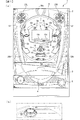
まず、遊技機の一例であるパチンコ遊技機1の全体の構成について説明する。図1はパチンコ遊技機1を正面からみた正面図である。
First, the overall configuration of a
パチンコ遊技機1は、縦長の方形状に形成された外枠(図示せず)と、外枠の内側に開閉可能に取り付けられた遊技枠とで構成される。また、パチンコ遊技機1は、遊技枠に開閉可能に設けられている額縁状に形成されたガラス扉枠2を有する。遊技枠は、外枠に対して開閉自在に設置される前面枠(図示せず)と、機構部品等が取り付けられる機構板(図示せず)と、それらに取り付けられる種々の部品(後述する遊技盤6を除く)とを含む構造体である。
The
ガラス扉枠2の下部表面には打球供給皿(上皿)3がある。打球供給皿3の下部には、打球供給皿3に収容しきれない遊技球を貯留する余剰球受皿4や、打球を発射する打球操作ハンドル(操作ノブ)5が設けられている。また、ガラス扉枠2の背面には、遊技盤6が着脱可能に取り付けられている。尚、遊技盤6は、それを構成する板状体と、その板状体に取り付けられた種々の部品とを含む構造体である。また、遊技盤6の前面には、打ち込まれた遊技球が流下可能な遊技領域7が形成されている。
On the lower surface of the
遊技領域7の中央付近には、液晶表示装置(LCD)で構成された演出表示装置9が設けられている。演出表示装置9では、第1特別図柄または第2特別図柄の可変表示に同期した演出図柄(飾り図柄)の可変表示(変動表示ともいう)が行われる。よって、演出表示装置9は、識別情報としての演出図柄(飾り図柄)の可変表示(変動表示)を行う可変表示装置に相当する。演出表示装置9は、演出制御基板に搭載されている演出制御用マイクロコンピュータによって制御される。演出制御用マイクロコンピュータが、第1特別図柄表示器8aで第1特別図柄の可変表示が実行されているときに、その可変表示に伴って演出表示装置9で演出表示を実行させ、第2特別図柄表示器8bで第2特別図柄の可変表示が実行されているときに、その可変表示に伴って演出表示装置で演出表示を実行させるので、遊技の進行状況を把握しやすくすることができる。
An
遊技盤6における演出表示装置9の上部の左側には、識別情報としての第1特別図柄を可変表示する第1特別図柄表示器(第1可変表示手段)8aが設けられている。この実施例では、第1特別図柄表示器8aは、複数種類の記号を可変表示可能な簡易で小型の表示器(例えば7セグメントLED)で実現されている。すなわち、第1特別図柄表示器8aは、複数種類の記号を可変表示するように構成されている。遊技盤6における演出表示装置9の上部の右側には、識別情報としての第2特別図柄を可変表示する第2特別図柄表示器(第2可変表示手段)8bが設けられている。第2特別図柄表示器8bは、複数種類の記号を可変表示可能な簡易で小型の表示器(例えば7セグメントLED)で実現されている。すなわち、第2特別図柄表示器8bは、複数種類の記号を可変表示するように構成されている。
A first special symbol display (first variable display means) 8 a that variably displays a first special symbol as identification information is provided on the left side of the top of the
この実施例では、第1特別図柄の種類と第2特別図柄の種類とは同じ(例えば、ともに0〜9の数字)であるが、種類が異なっていてもよい。また、第1特別図柄表示器8aおよび第2特別図柄表示器8bは、それぞれ、例えば、0〜9、00〜99等の数字やアルファベット等の文字を可変表示するように構成されていてもよい。
In this embodiment, the type of the first special symbol and the type of the second special symbol are the same (for example, both 0 to 9), but the types may be different. The first
以下、第1特別図柄と第2特別図柄とを特別図柄と総称することがあり、第1特別図柄表示器8aと第2特別図柄表示器8bとを特別図柄表示器と総称することがある。
Hereinafter, the first special symbol and the second special symbol may be collectively referred to as a special symbol, and the first
第1特別図柄または第2特別図柄の可変表示は、可変表示の実行条件である第1始動条件または第2始動条件が成立(例えば、遊技球が第1始動入賞口13または第2始動入賞口14に入賞したこと)した後、可変表示の開始条件(例えば、保留記憶数が0でない場合であって、第1特別図柄および第2特別図柄の可変表示が実行されていない状態であり、かつ、大当り遊技が実行されていない状態)が成立したことにもとづいて開始され、可変表示時間(変動時間)が経過すると表示結果(停止図柄)を導出表示する。尚、入賞とは、入賞口などのあらかじめ入賞領域として定められている領域に遊技球が入ったことである。また、表示結果を導出表示するとは、図柄(識別情報の例)を最終的に停止表示させることである。
For the variable display of the first special symbol or the second special symbol, the first start condition or the second start condition, which is the variable display execution condition, is satisfied (for example, the game ball has the first
演出表示装置9は、第1特別図柄表示器8aでの第1特別図柄の可変表示時間中、および第2特別図柄表示器8bでの第2特別図柄の可変表示時間中に、装飾用(演出用)の図柄としての演出図柄(飾り図柄ともいう)の可変表示を行う。第1特別図柄表示器8aにおける第1特別図柄の可変表示と、演出表示装置9における演出図柄の可変表示とは同期している。また、第2特別図柄表示器8bにおける第2特別図柄の可変表示と、演出表示装置9における演出図柄の可変表示とは同期している。同期とは、可変表示の開始時点および終了時点がほぼ同じ(全く同じでもよい。)であって、可変表示の期間がほぼ同じ(全く同じでもよい。)であることをいう。また、第1特別図柄表示器8aにおいて大当り図柄が停止表示されるときと、第2特別図柄表示器8bにおいて大当り図柄が停止表示されるときには、演出表示装置9において大当りを想起させるような演出図柄の組合せが停止表示される。
The
演出表示装置9の下方には、第1始動入賞口13を有する入賞装置が設けられている。第1始動入賞口13に入賞した遊技球は、遊技盤6の背面に導かれ、第1始動口スイッチ13aによって検出される。
A winning device having a first
また、第1始動入賞口(第1始動口)13を有する入賞装置の下方には、遊技球が入賞可能な第2始動入賞口14を有する可変入賞球装置15が設けられている。第2始動入賞口(第2始動口)14に入賞した遊技球は、遊技盤6の背面に導かれ、第2始動口スイッチ14aによって検出される。可変入賞球装置15は、ソレノイド16によって開状態とされる。可変入賞球装置15が開状態になることによって、遊技球が第2始動入賞口14に入賞可能になり(始動入賞し易くなり)、遊技者にとって有利な状態になる。可変入賞球装置15が開状態になっている状態では、第1始動入賞口13よりも、第2始動入賞口14に遊技球が入賞しやすい。また、可変入賞球装置15が閉状態になっている状態では、遊技球は第2始動入賞口14に入賞しない。尚、可変入賞球装置15が閉状態になっている状態において、入賞はしづらいものの、入賞することは可能である(すなわち、遊技球が入賞しにくい)ように構成されていてもよい。
A variable winning
以下、第1始動入賞口13と第2始動入賞口14とを総称して始動入賞口または始動口ということがある。
Hereinafter, the first
可変入賞球装置15が開放状態に制御されているときには可変入賞球装置15に向かう遊技球は第2始動入賞口14に極めて入賞しやすい。そして、第1始動入賞口13は演出表示装置9の直下に設けられているが、演出表示装置9の下端と第1始動入賞口13との間の間隔をさらに狭めたり、第1始動入賞口13の周辺で釘を密に配置したり、第1始動入賞口13の周辺での釘配列を、遊技球を第1始動入賞口13に導きづらくして、第2始動入賞口14の入賞率の方を第1始動入賞口13の入賞率よりもより高くするようにしてもよい。
When the variable winning
第1特別図柄表示器8aの下部には、第1始動入賞口13に入った有効入賞球数すなわち第1保留記憶数(保留記憶を、始動記憶または始動入賞記憶ともいう。)を表示する4つの表示器(例えば、LED)からなる第1特別図柄保留記憶表示器18aが設けられている。第1特別図柄保留記憶表示器18aは、有効始動入賞がある毎に、点灯する表示器の数を1増やす。そして、第1特別図柄表示器8aでの可変表示が開始される毎に、点灯する表示器の数を1減らす。
Below the first
第2特別図柄表示器8bの下部には、第2始動入賞口14に入った有効入賞球数すなわち第2保留記憶数を表示する4つの表示器(例えば、LED)からなる第2特別図柄保留記憶表示器18bが設けられている。第2特別図柄保留記憶表示器18bは、有効始動入賞がある毎に、点灯する表示器の数を1増やす。そして、第2特別図柄表示器8bでの可変表示が開始される毎に、点灯する表示器の数を1減らす。
Below the second
また、演出表示装置9の表示画面には、第1保留記憶数を表示する第1保留記憶表示部18cと、第2保留記憶数を表示する第2保留記憶表示部18dとが設けられている。尚、第1保留記憶数と第2保留記憶数との合計である合計数(合算保留記憶数)を表示する領域(合算保留記憶表示部)が設けられるようにしてもよい。そのように、合計数を表示する合算保留記憶表示部が設けられているようにすれば、可変表示の開始条件が成立していない実行条件の成立数の合計を把握しやすくすることができる。
Further, the display screen of the
尚、この実施例では、図1に示すように、第2始動入賞口14に対してのみ開閉動作を行う可変入賞球装置15が設けられているが、第1始動入賞口13および第2始動入賞口14のいずれについても開閉動作を行う可変入賞球装置が設けられている構成であってもよい。
In this embodiment, as shown in FIG. 1, there is provided a variable winning
また、図1に示すように、可変入賞球装置15の下方には、特別可変入賞球装置20が設けられている。特別可変入賞球装置20は開閉板を備え、第1特別図柄表示器8aに特定表示結果(大当り図柄)が導出表示されたとき、および第2特別図柄表示器8bに特定表示結果(大当り図柄)が導出表示されたときに生起する特定遊技状態(大当り遊技状態)においてソレノイド21によって開閉板が開放状態に制御されることによって、入賞領域となる大入賞口が開放状態になる。大入賞口に入賞した遊技球はカウントスイッチ23で検出される。
Further, as shown in FIG. 1, a special variable winning
遊技盤6の右側方下部には、普通図柄表示器10が設けられている。普通図柄表示器10は、普通図柄と呼ばれる複数種類の識別情報(例えば、「○」および「×」)を可変表示する。
A
遊技球がゲート32を通過しゲートスイッチ32aで検出されると、普通図柄表示器10の表示の可変表示が開始される。この実施例では、上下のランプ(点灯時に図柄が視認可能になる)が交互に点灯することによって可変表示が行われ、例えば、可変表示の終了時に下側のランプが点灯すれば当りとなる。そして、普通図柄表示器10における停止図柄が所定の図柄(当り図柄)である場合に、可変入賞球装置15が所定回数、所定時間だけ開状態になる。すなわち、可変入賞球装置15の状態は、普通図柄の停止図柄が当り図柄である場合に、遊技者にとって不利な状態から有利な状態(第2始動入賞口14に遊技球が入賞可能な状態)に変化する。普通図柄表示器10の近傍には、ゲート32を通過した入賞球数を表示する4つの表示器(例えば、LED)を有する普通図柄保留記憶表示器41が設けられている。ゲート32への遊技球の通過がある毎に、すなわちゲートスイッチ32aによって遊技球が検出される毎に、普通図柄保留記憶表示器41は点灯する表示器を1増やす。そして、普通図柄表示器10の可変表示が開始される毎に、点灯する表示器を1減らす。さらに、通常状態に比べて大当りとすることに決定される確率が高い状態である高確率状態(確変状態)では、普通図柄表示器10における停止図柄が当り図柄になる確率が高められるとともに、可変入賞球装置15の開放時間が長くなり、かつ、開放回数が増加される。すなわち、遊技球が始動入賞しやすくなる(つまり、特別図柄表示器8a,8bや演出表示装置9における可変表示の実行条件が成立しやすくなる)ように制御された遊技状態である高ベース状態に移行する。また、この実施例では、時短状態(特別図柄の可変表示時間が短縮される遊技状態)においても、可変入賞球装置15の開放時間が長くなり、かつ、開放回数が増加される。
When the game ball passes through the
尚、可変入賞球装置15が開状態となる時間を延長する(開放延長状態ともいう)のでなく、普通図柄表示器10における停止図柄が当り図柄になる確率が高められる普通図柄確変状態に移行することによって、高ベース状態に移行してもよい。普通図柄表示器10における停止図柄が所定の図柄(当り図柄)となると、可変入賞球装置15が所定回数、所定時間だけ開状態になる。この場合、普通図柄確変状態に移行制御することによって、普通図柄表示器10における停止図柄が当り図柄になる確率が高められ、可変入賞球装置15が開状態となる頻度が高まる。従って、普通図柄確変状態に移行すれば、可変入賞球装置15の開放時間と開放回数が高められ、始動入賞しやすい状態(高ベース状態)となる。すなわち、可変入賞球装置15の開放時間と開放回数は、普通図柄の停止図柄が当り図柄であったり、特別図柄の停止図柄が確変図柄である場合等に高められ、遊技者にとって不利な状態から有利な状態(始動入賞しやすい状態)に変化する。尚、開放回数が高められることは、閉状態から開状態になることも含む概念である。
It should be noted that instead of extending the time during which the variable winning
また、普通図柄表示器10における普通図柄の変動時間(可変表示期間)が短縮される普通図柄時短状態に移行することによって、高ベース状態に移行してもよい。普通図柄時短状態では、普通図柄の変動時間が短縮されるので、普通図柄の変動が開始される頻度が高くなり、結果として普通図柄が当りとなる頻度が高くなる。従って、普通図柄が当りとなる頻度が高くなることによって、可変入賞球装置15が開状態となる頻度が高くなり、始動入賞しやすい状態(高ベース状態)となる。
Moreover, you may transfer to a high base state by shifting to the normal symbol time short state where the fluctuation time (variable display period) of the normal symbol in the
また、特別図柄や演出図柄の変動時間(可変表示期間)が短縮される時短状態に移行することによって、特別図柄や演出図柄の変動時間が短縮されるので、有効な始動入賞が発生しやすくなり大当り遊技が行われる可能性が高まる。 Also, by shifting to the short time state when the variation time (variable display period) of special symbols and production symbols is shortened, the variation time of special symbols and production symbols is shortened, so that effective start winnings are likely to occur. The possibility that a big hit game is played increases.
さらに、上記に示した全ての状態(開放延長状態、普通図柄確変状態、普通図柄時短状態および特別図柄時短状態)に移行させることによって、始動入賞しやすくなる(高ベース状態に移行する)ようにしてもよい。また、上記に示した各状態(開放延長状態、普通図柄確変状態、普通図柄時短状態および特別図柄時短状態)のうちのいずれか複数の状態に移行させることによって、始動入賞しやすくなる(高ベース状態に移行する)ようにしてもよい。 Furthermore, by making transitions to all the states shown above (open extended state, normal symbol probability change state, normal symbol short time state, and special symbol short time state), it will be easier to win a start (shift to a high base state). May be. In addition, it is easier to win a start (high base) by shifting to any one of the above states (open extended state, normal symbol probability changing state, normal symbol short time state, and special symbol short time state). Transition to a state).
遊技盤6の遊技領域7の左右周辺には、遊技中に点滅表示される装飾LED25が設けられ、下部には、入賞しなかった打球が取り込まれるアウト口26がある。また、遊技領域7の外側の左右上部には、所定の音声出力として効果音や音声を発声する2つのスピーカ27R,27Lが設けられている。遊技領域7の外周上部、外周左部および外周右部には、前面枠に設けられた天枠LED28a、左枠LED28bおよび右枠LED28cが設けられている。また、左枠LED28bの近傍には賞球残数があるときに点灯する賞球LED51が設けられ、右枠LED28cの近傍には補給球が切れたときに点灯する球切れLED52が設けられている。天枠LED28a、左枠LED28bおよび右枠LED28cおよび装飾LED25は、パチンコ遊技機1に設けられている演出用の発光体の一例である。尚、上述した演出用(装飾用)の各種LEDの他にも演出のためのLEDやランプが設置されている。
On the left and right sides of the
また、打球供給皿3を構成する部材に、遊技者が操作可能な操作手段としての操作部50が設けられている。図1(b)に示すように、操作部50には、遊技者が押圧操作することが可能とされ、内部にLED50bを内在することで点灯可能な透明樹脂部材から成る押圧操作部49が設けられている。尚、押圧操作部49の下方には、押圧操作部49の押圧操作を検出するための操作スイッチ50aが設けられている(図3参照)。
In addition, an
遊技機には、遊技者が打球操作ハンドル5を操作することに応じて駆動モータを駆動し、駆動モータの回転力を利用して遊技球を遊技領域7に発射する打球発射装置(図示せず)が設けられている。打球発射装置から発射された遊技球は、遊技領域7を囲むように円形状に形成された打球レールを通って遊技領域7に入り、その後、遊技領域7を下りてくる。遊技球が第1始動入賞口13に入り第1始動口スイッチ13aで検出されると、第1特別図柄の可変表示を開始できる状態であれば(例えば、特別図柄の可変表示が終了し、第1の開始条件が成立したこと)、第1特別図柄表示器8aにおいて第1特別図柄の可変表示(変動)が開始されるとともに、演出表示装置9において演出図柄(飾り図柄)の可変表示が開始される。すなわち、第1特別図柄および演出図柄の可変表示は、第1始動入賞口13への入賞に対応する。第1特別図柄の可変表示を開始できる状態でなければ、第1保留記憶数が上限値に達していないことを条件として、第1保留記憶数を1増やす。
In the gaming machine, a ball striking device (not shown) that drives a driving motor in response to a player operating the batting operation handle 5 and uses the rotational force of the driving motor to launch a gaming ball to the gaming area 7. ) Is provided. A game ball launched from the ball striking device enters the
遊技球が第2始動入賞口14に入り第2始動口スイッチ14aで検出されると、第2特別図柄の可変表示を開始できる状態であれば(例えば、特別図柄の可変表示が終了し、第2の開始条件が成立したこと)、第2特別図柄表示器8bにおいて第2特別図柄の可変表示(変動)が開始されるとともに、演出表示装置9において演出図柄(飾り図柄)の可変表示が開始される。すなわち、第2特別図柄および演出図柄の可変表示は、第2始動入賞口14への入賞に対応する。第2特別図柄の可変表示を開始できる状態でなければ、第2保留記憶数が上限値に達していないことを条件として、第2保留記憶数を1増やす。
When the game ball enters the second
図2は、主基板(遊技制御基板)31における回路構成の一例を示すブロック図である。尚、図2には、払出制御基板37および演出制御基板80等も示されている。主基板31には、プログラムに従ってパチンコ遊技機1を制御する遊技制御用マイクロコンピュータ(遊技制御手段に相当)560が搭載されている。遊技制御用マイクロコンピュータ560は、ゲーム制御(遊技進行制御)用のプログラム等を記憶するROM54、ワークメモリとして使用される記憶手段としてのRAM55、プログラムに従って制御動作を行うCPU56およびI/Oポート部57を含む。この実施例では、ROM54およびRAM55は遊技制御用マイクロコンピュータ560に内蔵されている。すなわち、遊技制御用マイクロコンピュータ560は、1チップマイクロコンピュータである。1チップマイクロコンピュータには、少なくともCPU56のほかRAM55が内蔵されていればよく、ROM54は外付けであっても内蔵されていてもよい。また、I/Oポート部57は、外付けであってもよい。遊技制御用マイクロコンピュータ560には、さらに、ハードウェア乱数(ハードウェア回路が発生する乱数)を発生する乱数回路503が内蔵されている。
FIG. 2 is a block diagram showing an example of the circuit configuration of the main board (game control board) 31. 2 also shows the
尚、遊技制御用マイクロコンピュータ560においてCPU56がROM54に格納されているプログラムに従って制御を実行するので、以下、遊技制御用マイクロコンピュータ560(またはCPU56)が実行する(または、処理を行う)ということは、具体的には、CPU56がプログラムに従って制御を実行することである。このことは、主基板31以外の他の基板に搭載されているマイクロコンピュータについても同様である。
In the
乱数回路503は、特別図柄の可変表示の表示結果により大当りとするか否か判定するための判定用の乱数を発生するために用いられるハードウェア回路である。乱数回路503は、初期値(例えば、0)と上限値(例えば、65535)とが設定された数値範囲内で、数値データを、設定された更新規則に従って更新し、ランダムなタイミングで発生する始動入賞時が数値データの読出(抽出)時であることにもとづいて、読出される数値データが乱数値となる乱数発生機能を有する。
The
乱数回路503は、数値データの更新範囲の選択設定機能(初期値の選択設定機能、および、上限値の選択設定機能)、数値データの更新規則の選択設定機能、および数値データの更新規則の選択切換え機能等の各種の機能を有する。このような機能によって、生成する乱数のランダム性を向上させることができる。
The
また、遊技制御用マイクロコンピュータ560は、乱数回路503が更新する数値データの初期値を設定する機能を有している。例えば、ROM54等の所定の記憶領域に記憶された遊技制御用マイクロコンピュータ560のIDナンバ(遊技制御用マイクロコンピュータ560の各製品ごとに異なる数値で付与されたIDナンバ)を用いて所定の演算を行って得られた数値データを、乱数回路503が更新する数値データの初期値として設定する。そのような処理を行うことによって、乱数回路503が発生する乱数のランダム性をより向上させることができる。
Further, the
遊技制御用マイクロコンピュータ560は、第1始動口スイッチ13aまたは第2始動口スイッチ14aへの始動入賞が生じたときに乱数回路503から数値データをランダムRとして読み出し、特別図柄および演出図柄の変動開始時にランダムRにもとづいて特定の表示結果としての大当り表示結果にするか否か、すなわち、大当りとするか否かを決定する。そして、大当りとすると決定したときに、遊技状態を遊技者にとって有利な特定遊技状態としての大当り遊技状態に移行させる。
The
また、RAM55は、その一部または全部が電源基板において作成されるバックアップ電源によってバックアップされている不揮発性記憶手段としてのバックアップRAMである。すなわち、遊技機に対する電力供給が停止しても、所定期間(バックアップ電源としてのコンデンサが放電してバックアップ電源が電力供給不能になるまで)は、RAM55の一部または全部の内容は保存される。特に、少なくとも、遊技状態すなわち遊技制御手段の制御状態に応じたデータ(特別図柄プロセスフラグや合算保留記憶数カウンタや確変フラグの値など)と未払出賞球数を示すデータは、バックアップRAMに保存される。遊技制御手段の制御状態に応じたデータとは、停電等が生じた後に復旧した場合に、そのデータにもとづいて、制御状態を停電等の発生前に復旧させるために必要なデータである。また、制御状態に応じたデータと未払出賞球数を示すデータとを遊技の進行状態を示すデータ(進行状態データ)と定義する。尚、この実施例では、RAM55の全部が、電源バックアップされているとする。
The
遊技制御用マイクロコンピュータ560のリセット端子には、電源基板からのリセット信号(図示せず)が入力される。電源基板には、遊技制御用マイクロコンピュータ560等に供給されるリセット信号を生成するリセット回路が搭載されている。尚、リセット信号がハイレベルになると遊技制御用マイクロコンピュータ560等は動作可能状態になり、リセット信号がローレベルになると遊技制御用マイクロコンピュータ560等は動作停止状態になる。従って、リセット信号がハイレベルである期間は、遊技制御用マイクロコンピュータ560等の動作を許容する許容信号が出力されていることになり、リセット信号がローレベルである期間は、遊技制御用マイクロコンピュータ560等の動作を停止させる動作停止信号が出力されていることになる。尚、リセット回路をそれぞれの電気部品制御基板(電気部品を制御するためのマイクロコンピュータが搭載されている基板)に搭載してもよい。
A reset signal (not shown) from the power supply board is input to the reset terminal of the
さらに、遊技制御用マイクロコンピュータ560の入力ポートには、電源基板からの電源電圧が所定値以下に低下したことを示す電源断信号が入力される。すなわち、電源基板には、遊技機において使用される所定電圧(例えば、DC30VやDC5Vなど)の電圧値を監視して、電圧値があらかじめ定められた所定値にまで低下すると(電源電圧の低下を検出すると)、その旨を示す電源断信号を出力する電源監視回路が搭載されている。また、遊技制御用マイクロコンピュータ560の入力ポートには、RAMの内容をクリアすることを指示するためのクリアスイッチが操作されたことを示すクリア信号(図示せず)が入力される。
Further, a power-off signal indicating that the power supply voltage from the power supply board has dropped below a predetermined value is input to the input port of the
また、ゲートスイッチ32a、第1始動口スイッチ13a、第2始動口スイッチ14aおよびカウントスイッチ23からの検出信号を遊技制御用マイクロコンピュータ560に与える入力ドライバ回路58も主基板31に搭載されている。また、可変入賞球装置15を開閉するソレノイド16、および大入賞口を形成する特別可変入賞球装置20を開閉するソレノイド21を遊技制御用マイクロコンピュータ560からの指令に従って駆動する出力回路59も主基板31に搭載されている。さらに、大当り遊技状態の発生を示す大当り情報や、確変状態や時短状態等の遊技状態の発生を示す情報等の情報出力信号をホールコンピュータや、パチンコ遊技機1の上方位置にパチンコ遊技機1に対応して設置されている呼び出しランプ(図示略)等の外部装置に対して出力する情報出力回路53も主基板31に搭載されている。
Further, an
この実施例では、演出制御基板80に搭載されている演出制御手段(演出制御用マイクロコンピュータで構成される。)が、中継基板77を介して遊技制御用マイクロコンピュータ560から演出内容を指示する演出制御コマンドを受信し、演出図柄を可変表示する演出表示装置9との表示制御を行う。
In this embodiment, the effect control means (configured by the effect control microcomputer) mounted on the
図3は、中継基板77、演出制御基板80、ランプドライバ基板35および音声出力基板70の回路構成例を示すブロック図である。尚、図3に示す例では、ランプドライバ基板35および音声出力基板70には、マイクロコンピュータは搭載されていないが、マイクロコンピュータを搭載してもよい。また、ランプドライバ基板35および音声出力基板70を設けずに、演出制御に関して演出制御基板80のみを設けてもよい。
FIG. 3 is a block diagram illustrating a circuit configuration example of the
演出制御基板80は、演出制御用CPU101およびRAMを含む演出制御用マイクロコンピュータ100を搭載している。尚、RAMは外付けであってもよい。演出制御基板80において、演出制御用CPU101は、内蔵または外付けのROM(図示せず)に格納されたプログラムに従って動作し、中継基板77を介して入力される主基板31からの取込信号(演出制御INT信号)に応じて、入力ドライバ102および入力ポート103を介して演出制御コマンドを受信する。また、演出制御用CPU101は、演出制御コマンドにもとづいて、VDP(ビデオディスプレイプロセッサ)109に演出表示装置9の表示制御を行わせる。
The
この実施例では、演出制御用マイクロコンピュータ100と共動して演出表示装置9の表示制御を行うVDP109が演出制御基板80に搭載されている。VDP109は、演出制御用マイクロコンピュータ100とは独立したアドレス空間を有し、そこにVRAMをマッピングする。VRAMは、VDPによって生成された画像データを展開するためのバッファメモリである。そして、VDP109は、VRAM内の画像データを演出表示装置9に出力する。
In this embodiment, a
演出制御用CPU101は、受信した演出制御コマンドに従ってキャラクタROM(図示せず)から必要なデータを読み出す。キャラクタROMは、演出表示装置9に表示されるキャラクタ画像データ、具体的には、人物、文字、図形または記号等(演出図柄を含む)をあらかじめ格納しておくためのものである。演出制御用CPU101は、キャラクタROMから読み出したデータをVDP109に出力する。VDP109は、演出制御用CPU101から入力されたデータにもとづいて表示制御を実行する。
The
演出制御コマンドおよび演出制御INT信号は、演出制御基板80において、まず、入力ドライバ102に入力する。入力ドライバ102は、中継基板77から入力された信号を演出制御基板80の内部に向かう方向にしか通過させない(演出制御基板80の内部から中継基板77への方向には信号を通過させない)信号方向規制手段としての単方向性回路でもある。
The effect control command and the effect control INT signal are first input to the
中継基板77には、主基板31から入力された信号を演出制御基板80に向かう方向にしか通過させない(演出制御基板80から中継基板77への方向には信号を通過させない)信号方向規制手段としての単方向性回路74が搭載されている。単方向性回路として、例えばダイオードやトランジスタが使用される。図3には、ダイオードが例示されている。また、単方向性回路は、各信号毎に設けられる。さらに、単方向性回路である出力ポート571を介して主基板31から演出制御コマンドおよび演出制御INT信号が出力されるので、中継基板77から主基板31の内部に向かう信号が規制される。すなわち、中継基板77からの信号は主基板31の内部(遊技制御用マイクロコンピュータ560側)に入り込まない。尚、出力ポート571は、図2に示されたI/Oポート部57の一部である。また、出力ポート571の外側(中継基板77側)に、さらに、単方向性回路である信号ドライバ回路が設けられていてもよい。
As a signal direction regulating means, the signal inputted from the
さらに、演出制御用CPU101は、出力ポート105を介してランプドライバ基板35に対してLEDを駆動する信号を出力する。また、演出制御用CPU101は、出力ポート104を介して音声出力基板70に対して音番号データを出力する。
Further, the
ランプドライバ基板35において、LEDを駆動する信号は、入力ドライバ351を介してLEDドライバ352に入力される。LEDドライバ352は、駆動信号を天枠LED28a、左枠LED28b、右枠LED28cなどの枠側に設けられている各LEDに供給する。また、遊技盤側に設けられている装飾LED25に駆動信号を供給する。尚、LED以外の発光体が設けられている場合には、それを駆動する駆動回路(ドライバ)がランプドライバ基板35に搭載される。
In the
音声出力基板70において、音番号データは、入力ドライバ702を介して音声合成用IC703に入力される。音声合成用IC703は、音番号データに応じた音声や効果音を発生し増幅回路705に出力する。増幅回路705は、音声合成用IC703の出力レベルを、ボリューム706で設定されている音量に応じたレベルに増幅した音声信号をスピーカ27R,27Lに出力する。音声データROM704には、音番号データに応じた制御データが格納されている。音番号データに応じた制御データは、所定期間(例えば演出図柄の変動期間)における効果音または音声の出力態様を時系列的に示すデータの集まりである。
In the
また、演出制御用CPU101は、入出力ポート106を介して操作部50に接続されており、該入出力ポート106を介して操作部50内のLED50bを駆動する信号を出力するとともに、操作部50内の操作スイッチ50aから遊技者の押圧操作に応じて出力される操作信号が入力される。
The
次に、遊技機の動作について説明する。図4は、主基板31における遊技制御用マイクロコンピュータ560が実行するメイン処理を示すフローチャートである。遊技機に対して電源が投入され電力供給が開始されると、リセット信号が入力されるリセット端子の入力レベルがハイレベルになり、遊技制御用マイクロコンピュータ560(具体的には、CPU56)は、プログラムの内容が正当か否か確認するための処理であるセキュリティチェック処理を実行した後、ステップS1以降のメイン処理を開始する。メイン処理において、CPU56は、まず、必要な初期設定を行う。
Next, the operation of the gaming machine will be described. FIG. 4 is a flowchart showing a main process executed by the
初期設定処理において、CPU56は、まず、割込禁止に設定する(ステップS1)。次に、割込モードを割込モード2に設定し(ステップS2)、スタックポインタにスタックポインタ指定アドレスを設定する(ステップS3)。そして、内蔵デバイスの初期化(内蔵デバイス(内蔵周辺回路)であるCTC(カウンタ/タイマ)およびPIO(パラレル入出力ポート)の初期化など)を行った後(ステップS4)、RAMをアクセス可能状態に設定する(ステップS5)。尚、割込モード2は、CPU56が内蔵する特定レジスタ(Iレジスタ)の値(1バイト)と内蔵デバイスが出力する割込ベクタ(1バイト:最下位ビット0)とから合成されるアドレスが、割込番地を示すモードである。
In the initial setting process, the
次いで、CPU56は、入力ポートを介して入力されるクリアスイッチ(例えば、電源基板に搭載されている。)の出力信号(クリア信号)の状態を確認する(ステップS6)。その確認においてオンを検出した場合には、CPU56は、通常の初期化処理(ステップS10〜S15)を実行する。
Next, the
クリアスイッチがオンの状態でない場合には、遊技機への電力供給が停止したときにバックアップRAM領域のデータ保護処理(例えばパリティデータの付加等の電力供給停止時処理)が行われたか否か確認する(ステップS7)。そのような保護処理が行われていないことを確認したら、CPU56は初期化処理を実行する。バックアップRAM領域にバックアップデータがあるか否かは、例えば、電力供給停止時処理においてバックアップRAM領域に設定されるバックアップフラグの状態によって確認される。
If the clear switch is not on, check whether data protection processing of the backup RAM area (for example, power supply stop processing such as addition of parity data) was performed when power supply to the gaming machine was stopped (Step S7). When it is confirmed that such protection processing is not performed, the
電力供給停止時処理が行われたことを確認したら、CPU56は、バックアップRAM領域のデータチェックを行う(ステップS8)。この実施例では、データチェックとしてパリティチェックを行う。よって、ステップS8では、算出したチェックサムと、電力供給停止時処理で同一の処理によって算出され保存されているチェックサムとを比較する。不測の停電等の電力供給停止が生じた後に復旧した場合には、バックアップRAM領域のデータは保存されているはずであるから、チェック結果(比較結果)は正常(一致)になる。チェック結果が正常でないということは、バックアップRAM領域のデータが、電力供給停止時のデータとは異なっていることを意味する。そのような場合には、内部状態を電力供給停止時の状態に戻すことができないので、電力供給の停止からの復旧時でない電源投入時に実行される初期化処理を実行する。
When it is confirmed that the power supply stop process has been performed, the
チェック結果が正常であれば、CPU56は、遊技制御手段の内部状態と演出制御手段等の電気部品制御手段の制御状態を電力供給停止時の状態に戻すための遊技状態復旧処理(ステップS41〜S43の処理)を行う。具体的には、ROM54に格納されているバックアップ時設定テーブルの先頭アドレスをポインタに設定し(ステップS41)、バックアップ時設定テーブルの内容を順次作業領域(RAM55内の領域)に設定する(ステップS42)。作業領域はバックアップ電源によって電源バックアップされている。バックアップ時設定テーブルには、作業領域のうち初期化してもよい領域についての初期化データが設定されている。ステップS41およびS42の処理によって、作業領域のうち初期化してはならない部分については、保存されていた内容がそのまま残る。初期化してはならない部分とは、例えば、電力供給停止前の遊技状態を示すデータ(特別図柄プロセスフラグ、確変フラグ、時短フラグなど)、出力ポートの出力状態が保存されている領域(出力ポートバッファ)、未払出賞球数を示すデータが設定されている部分などである。
If the check result is normal, the
また、CPU56は、電力供給復旧時の初期化コマンドとしての停電復旧指定コマンドを送信する(ステップS43)。そして、ステップS14に移行する。尚、この実施例では、CPU56は、ステップS43の処理において、バックアップRAMに保存されていた合算保留記憶数カウンタの値を設定した合算保留記憶数指定コマンドも演出制御基板80に対して送信する。
Further, the
尚、この実施例では、バックアップフラグとチェックデータとの双方を用いてバックアップRAM領域のデータが保存されているか否か確認しているが、いずれか一方のみを用いてもよい。すなわち、バックアップフラグとチェックデータとのいずれかを、遊技状態復旧処理を実行するための契機としてもよい。 In this embodiment, it is confirmed whether or not the data in the backup RAM area is stored using both the backup flag and the check data, but only one of them may be used. That is, either the backup flag or the check data may be used as an opportunity for executing the game state restoration process.
初期化処理では、CPU56は、まず、RAMクリア処理を行う(ステップS10)。尚、RAMクリア処理によって、所定のデータ(例えば、普通図柄当り判定用乱数を生成するためのカウンタのカウント値のデータ)は0に初期化されるが、任意の値またはあらかじめ決められている値に初期化するようにしてもよい。また、RAM55の全領域を初期化せず、所定のデータ(例えば、普通図柄当り判定用乱数を生成するためのカウンタのカウント値のデータ)をそのままにしてもよい。また、ROM54に格納されている初期化時設定テーブルの先頭アドレスをポインタに設定し(ステップS11)、初期化時設定テーブルの内容を順次作業領域に設定する(ステップS12)。
In the initialization process, the
ステップS11およびS12の処理によって、例えば、普通図柄当り判定用乱数カウンタ、特別図柄バッファ、総賞球数格納バッファ、特別図柄プロセスフラグなど制御状態に応じて選択的に処理を行うためのフラグに初期値が設定される。 By the processing in steps S11 and S12, for example, a normal symbol per-determining random number counter, a special symbol buffer, a total prize ball number storage buffer, a special symbol process flag, and other flags for selectively performing processing according to the control state are initialized. Value is set.
また、CPU56は、サブ基板(主基板31以外のマイクロコンピュータが搭載された基板。)を初期化するための初期化指定コマンド(遊技制御用マイクロコンピュータ560が初期化処理を実行したことを示すコマンドでもある。)をサブ基板に送信する(ステップS13)。例えば、演出制御用マイクロコンピュータ100は、初期化指定コマンドを受信すると、演出表示装置9において、遊技機の制御の初期化がなされたことを報知するための画面表示、すなわち初期化報知を行う。
Further, the
また、CPU56は、乱数回路503を初期設定する乱数回路設定処理を実行する(ステップS14)。CPU56は、例えば、乱数回路設定プログラムに従って処理を実行することによって、乱数回路503にランダムRの値を更新させるための設定を行う。
Further, the
そして、ステップS15において、CPU56は、所定時間(例えば2ms)毎に定期的にタイマ割込がかかるように遊技制御用マイクロコンピュータ560に内蔵されているCTCのレジスタの設定を行う。すなわち、初期値として例えば2msに相当する値が所定のレジスタ(時間定数レジスタ)に設定される。この実施例では、2ms毎に定期的にタイマ割込がかかるとする。
In step S15, the
初期化処理の実行(ステップS10〜S15)が完了すると、CPU56は、メイン処理で、表示用乱数更新処理(ステップS17)および初期値用乱数更新処理(ステップS18)を繰り返し実行する。表示用乱数更新処理および初期値用乱数更新処理を実行するときには割込禁止状態に設定し(ステップS16)、表示用乱数更新処理および初期値用乱数更新処理の実行が終了すると割込許可状態に設定する(ステップS19)。この実施例では、表示用乱数とは、大当りとしない場合の特別図柄の停止図柄を決定するための乱数や大当りとしない場合にリーチとするか否かを決定するための乱数であり、表示用乱数更新処理とは、表示用乱数を発生するためのカウンタのカウント値を更新する処理である。また、初期値用乱数更新処理とは、初期値用乱数を発生するためのカウンタのカウント値を更新する処理である。この実施例では、初期値用乱数とは、普通図柄に関して当りとするか否か決定するための乱数を発生するためのカウンタ(普通図柄当り判定用乱数発生カウンタ)のカウント値の初期値を決定するための乱数である。後述する遊技の進行を制御する遊技制御処理(遊技制御用マイクロコンピュータ560が、遊技機に設けられている演出表示装置、可変入賞球装置、球払出装置等の遊技用の装置を、自身で制御する処理、または他のマイクロコンピュータに制御させるために指令信号を送信する処理、遊技装置制御処理ともいう)において、普通図柄当り判定用乱数のカウント値が1周(普通図柄当り判定用乱数の取りうる値の最小値から最大値までの間の数値の個数分歩進したこと)すると、そのカウンタに初期値が設定される。
When the execution of the initialization process (steps S10 to S15) is completed, the
尚、この実施例では、リーチ演出は、演出表示装置9において可変表示される演出図柄(飾り図柄)を用いて実行される。また、特別図柄の表示結果を大当り図柄にする場合には、リーチ演出は常に実行される。特別図柄の表示結果を大当り図柄にしない場合には、遊技制御用マイクロコンピュータ560は、乱数を用いた抽選によって、リーチ演出を実行するか否か決定する。ただし、実際にリーチ演出の制御を実行するのは、演出制御用マイクロコンピュータ100である。
In this embodiment, the reach effect is executed using an effect symbol (decorative symbol) variably displayed on the
タイマ割込が発生すると、CPU56は、図5に示すステップS20〜S34のタイマ割込処理を実行する。タイマ割込処理において、まず、電源断信号が出力されたか否か(オン状態になったか否か)を検出する電源断検出処理を実行する(ステップS20)。電源断信号は、例えば電源基板に搭載されている電源監視回路が、遊技機に供給される電源の電圧の低下を検出した場合に出力する。そして、電源断検出処理において、CPU56は、電源断信号が出力されたことを検出したら、必要なデータをバックアップRAM領域に保存するための電力供給停止時処理を実行する。次いで、入力ドライバ回路58を介して、ゲートスイッチ32a、第1始動口スイッチ13a、第2始動口スイッチ14aおよびカウントスイッチ23の検出信号を入力し、それらの状態判定を行う(スイッチ処理:ステップS21)。
When the timer interrupt occurs, the
次に、CPU56は、第1特別図柄表示器8a、第2特別図柄表示器8b、普通図柄表示器10、第1特別図柄保留記憶表示器18a、第2特別図柄保留記憶表示器18b、普通図柄保留記憶表示器41の表示制御を行う表示制御処理を実行する(ステップS22)。第1特別図柄表示器8a、第2特別図柄表示器8bおよび普通図柄表示器10については、ステップS32,S33で設定される出力バッファの内容に応じて各表示器に対して駆動信号を出力する制御を実行する。
Next, the
また、遊技制御に用いられる普通図柄当り判定用乱数等の各判定用乱数を生成するための各カウンタのカウント値を更新する処理を行う(判定用乱数更新処理:ステップS23)。CPU56は、さらに、初期値用乱数および表示用乱数を生成するためのカウンタのカウント値を更新する処理を行う(初期値用乱数更新処理,表示用乱数更新処理:ステップS24,S25)。
Also, a process of updating the count value of each counter for generating each random number for determination such as a random number for determination per ordinary symbol used for game control is performed (determination random number update process: step S23). The
さらに、CPU56は、特別図柄プロセス処理を行う(ステップS26)。特別図柄プロセス処理では、第1特別図柄表示器8a、第2特別図柄表示器8bおよび大入賞口を所定の順序で制御するための特別図柄プロセスフラグに従って該当する処理を実行する。CPU56は、特別図柄プロセスフラグの値を、遊技状態に応じて更新する。
Further, the
次いで、普通図柄プロセス処理を行う(ステップS27)。普通図柄プロセス処理では、CPU56は、普通図柄表示器10の表示状態を所定の順序で制御するための普通図柄プロセスフラグに従って該当する処理を実行する。CPU56は、普通図柄プロセスフラグの値を、遊技状態に応じて更新する。
Next, normal symbol process processing is performed (step S27). In the normal symbol process, the
また、CPU56は、演出制御用マイクロコンピュータ100に演出制御コマンドを送出する処理を行う(演出制御コマンド制御処理:ステップS28)。
Further, the
さらに、CPU56は、例えばホール管理用コンピュータに供給される大当り情報、始動情報、確率変動情報などのデータを出力する情報出力処理を行う(ステップS29)。
Further, the
また、CPU56は、第1始動口スイッチ13a、第2始動口スイッチ14aおよびカウントスイッチ23の検出信号にもとづく賞球個数の設定などを行う賞球処理を実行する(ステップS30)。具体的には、第1始動口スイッチ13a、第2始動口スイッチ14aおよびカウントスイッチ23のいずれかがオンしたことにもとづく入賞検出に応じて、払出制御基板37に搭載されている払出制御用マイクロコンピュータに賞球個数を示す払出制御コマンド(賞球個数信号)を出力する。払出制御用マイクロコンピュータは、賞球個数を示す払出制御コマンドに応じて球払出装置97を駆動する。
Further, the
この実施例では、出力ポートの出力状態に対応したRAM領域(出力ポートバッファ)が設けられているのであるが、CPU56は、出力ポートの出力状態に対応したRAM領域におけるソレノイドのオン/オフに関する内容を出力ポートに出力する(ステップS31:出力処理)。
In this embodiment, a RAM area (output port buffer) corresponding to the output state of the output port is provided. However, the
また、CPU56は、特別図柄プロセスフラグの値に応じて特別図柄の演出表示を行うための特別図柄表示制御データを特別図柄表示制御データ設定用の出力バッファに設定する特別図柄表示制御処理を行う(ステップS32)。CPU56は、例えば、特別図柄プロセス処理でセットされる開始フラグがセットされると終了フラグがセットされるまで、変動速度が1コマ/0.2秒であれば、0.2秒が経過する毎に、出力バッファに設定される表示制御データの値を+1する。また、CPU56は、出力バッファに設定された表示制御データに応じて、ステップS22において駆動信号を出力することによって、第1特別図柄表示器8aおよび第2特別図柄表示器8bにおける第1特別図柄および第2特別図柄の可変表示を実行する。
Further, the
さらに、CPU56は、普通図柄プロセスフラグの値に応じて普通図柄の演出表示を行うための普通図柄表示制御データを普通図柄表示制御データ設定用の出力バッファに設定する普通図柄表示制御処理を行う(ステップS33)。CPU56は、例えば、普通図柄の変動に関する開始フラグがセットされると終了フラグがセットされるまで、普通図柄の変動速度が0.2秒ごとに表示状態(「○」および「×」)を切り替えるような速度であれば、0.2秒が経過する毎に、出力バッファに設定される表示制御データの値(例えば、「○」を示す1と「×」を示す0)を切り替える。また、CPU56は、出力バッファに設定された表示制御データに応じて、ステップS22において駆動信号を出力することによって、普通図柄表示器10における普通図柄の演出表示を実行する。
Further, the
その後、割込許可状態に設定し(ステップS34)、処理を終了する。 Thereafter, the interrupt permission state is set (step S34), and the process is terminated.
以上の制御によって、この実施例では、遊技制御処理は2ms毎に起動されることになる。尚、遊技制御処理は、タイマ割込処理におけるステップS21〜S33(ステップS29を除く。)の処理に相当する。また、この実施例では、タイマ割込処理で遊技制御処理が実行されているが、タイマ割込処理では例えば割込が発生したことを示すフラグのセットのみがなされ、遊技制御処理はメイン処理において実行されるようにしてもよい。 With the above control, in this embodiment, the game control process is started every 2 ms. The game control process corresponds to the process of steps S21 to S33 (excluding step S29) in the timer interrupt process. In this embodiment, the game control process is executed by the timer interrupt process. However, in the timer interrupt process, for example, only a flag indicating that an interrupt has occurred is set, and the game control process is performed in the main process. It may be executed.
第1特別図柄表示器8aまたは第2特別図柄表示器8bおよび演出表示装置9にはずれ図柄が停止表示される場合には、演出図柄の可変表示が開始されてから、演出図柄の可変表示状態がリーチ状態にならずに、リーチにならない所定の演出図柄の組合せが停止表示されることがある。このような演出図柄の可変表示態様を、可変表示結果がはずれ図柄になる場合における「非リーチ」(「通常はずれ」ともいう)の可変表示態様という。
When the shifted symbol is stopped and displayed on the first
第1特別図柄表示器8aまたは第2特別図柄表示器8bおよび演出表示装置9にはずれ図柄が停止表示される場合には、演出図柄の可変表示が開始されてから、演出図柄の可変表示状態がリーチ状態となった後にリーチ演出が実行され、最終的に大当り図柄とはならない所定の演出図柄の組合せが停止表示されることがある。このような演出図柄の可変表示結果を、可変表示結果が「はずれ」となる場合における「リーチ」(「リーチはずれ」ともいう)の可変表示態様という。
When the shifted symbol is stopped and displayed on the first
この実施例では、第1特別図柄表示器8aまたは第2特別図柄表示器8bに大当り図柄が停止表示される場合には、演出図柄の可変表示状態がリーチ状態になった後にリーチ演出が実行され、最終的に演出表示装置9における「左」、「中」、「右」の各図柄表示エリア9L、9C、9Rに、演出図柄が揃って停止表示される。
In this embodiment, when the big hit symbol is stopped and displayed on the first
図6は、あらかじめ用意された演出図柄の変動パターンを示す説明図である。図6に示すように、この実施例では、可変表示結果が「はずれ」であり演出図柄の可変表示態様が「非リーチ」である場合に対応した変動パターンとして、非リーチPA1−0〜非リーチPA1−4の変動パターンが用意されている。また、可変表示結果が「はずれ」であり演出図柄の可変表示態様が「リーチ」である場合に対応した変動パターンとして、ノーマルPA2−1(ノーマルリーチA)〜ノーマルPA2−2(ノーマルリーチB)、ノーマルPB2−1〜ノーマルPB2−2(ノーマルリーチC)、スーパーPB3−1〜PB3−4の変動パターンが用意されている。尚、図6に示すように、リーチしない場合に使用され擬似連の演出を伴う非リーチPA1−4の変動パターンについては、再変動が2回行われる。リーチする場合に使用され擬似連の演出を伴う変動パターンのうち、ノーマルPB2−1を用いる場合には、再変動が2回行われる。また、リーチする場合に使用され擬似連の演出を伴う変動パターンのうち、ノーマルPB2−2を用いる場合には、再変動が3回行われる。 FIG. 6 is an explanatory diagram showing the variation pattern of the effect symbol prepared in advance. As shown in FIG. 6, in this embodiment, non-reach PA1-0 to non-reach are used as a variation pattern corresponding to the case where the variable display result is “out of” and the variable display mode of the effect symbol is “non-reach”. A variation pattern of PA1-4 is prepared. In addition, as a variation pattern corresponding to the case where the variable display result is “out of” and the variable display mode of the production symbol is “reach”, normal PA2-1 (normal reach A) to normal PA2-2 (normal reach B), normal Variation patterns of PB2-1 to normal PB2-2 (normal reach C) and super PB3-1 to PB3-4 are prepared. In addition, as shown in FIG. 6, about the fluctuation pattern of non-reach PA1-4 which is used when not reaching and has the effect of pseudo-ream, re-change is performed twice. Of the variation patterns used for reaching and accompanied by pseudo-rendition, when normal PB2-1 is used, re-variation is performed twice. Of the fluctuation patterns used for reaching and accompanied by pseudo-continuous effects, when normal PB2-2 is used, re-variation is performed three times.
さらに、リーチする場合に使用され滑りの演出を伴う変動パターンのうち、スーパーPB3−3を用いる場合には、通常変動ではずれた後、滑りが行われてスーパーリーチに発展し、特別キャラクタ及び超熱パネルが出現する。また、リーチする場合に使用され擬似連の演出を伴う変動パターンのうち、スーパーPB3−4を用いる場合には、通常変動ではずれた後、再変動が3回行われてスーパーリーチに発展し、桜柄及び激熱パネルが出現する。 Furthermore, among the variation patterns that are used for reaching and have the effect of slipping, when using Super PB3-3, after shifting by the normal variation, slipping is performed to develop into super reach, and the special characters and super A thermal panel appears. Moreover, when using super PB3-4 among the fluctuation patterns with the effect of the pseudo-ream used for reaching, after deviating from the normal fluctuation, re-variation is performed three times to develop into super reach, Cherry blossoms and intense heat panels appear.
また、図6に示すように、この実施例では、特別図柄の可変表示結果が大当り図柄になる場合に対応した変動パターンとして、ノーマルPA2−3(ノーマルリーチA)〜ノーマルPA2−4(ノーマルリーチB)、ノーマルPB2−3〜ノーマルPB2−4(ノーマルリーチC)、スーパーPB3−5〜スーパーPB3−8、の変動パターンが用意されている。また、図6に示すように、大当り図柄になる場合に使用され擬似連の演出を伴う変動パターンのうち、ノーマルPB2−3を用いる場合には、再変動が2回行われる。また、リーチする場合に使用され擬似連の演出を伴う変動パターンのうち、ノーマルPB2−4を用いる場合には、再変動が3回行われる。 Further, as shown in FIG. 6, in this embodiment, normal PA2-3 (normal reach A) to normal PA2-4 (normal reach B) are used as variation patterns corresponding to the case where the variable symbol display result of the special symbol becomes a big hit symbol. Fluctuation patterns of normal PB2-3 to normal PB2-4 (normal reach C) and super PB3-5 to super PB3-8 are prepared. Further, as shown in FIG. 6, when the normal PB2-3 is used among the variation patterns that are used in the case of the big hit symbol and accompanied by the effect of the pseudo-continuous, the re-variation is performed twice. Of the fluctuation patterns used for reaching and accompanied by pseudo-rendition, when normal PB2-4 is used, re-variation is performed three times.
さらに、リーチする場合に使用され滑りの演出を伴う変動パターンのうち、スーパーPB3−7を用いる場合には、通常変動ではずれた後、滑りが行われてスーパーリーチに発展し、特別キャラクタ及び超熱パネルが出現する。また、リーチする場合に使用され擬似連の演出を伴う変動パターンのうち、スーパーPB3−8を用いる場合には、通常変動ではずれた後、再変動が3回行われてスーパーリーチに発展し、桜柄及び激熱パネルが出現する。 Furthermore, among the variation patterns that are used for reaching and have the effect of sliding, when using Super PB3-7, after shifting by the normal variation, sliding is performed to develop into super reach, and special characters and super A thermal panel appears. In addition, among the fluctuation patterns that are used for reaching and have the effect of pseudo-ream, when using the super PB3-8, after deviating from the normal fluctuation, the re-variation is performed three times to develop into the super reach. Cherry blossoms and intense heat panels appear.
尚、この実施例では、図6に示すように、変動パターンの種類に応じて変動時間が固定的に定められている場合(例えば、非リーチ短縮なしの場合は6.75秒で固定であり、擬似連ありのスーパーリーチAの場合には変動時間が26.75秒で固定であり、擬似連なしのスーパーリーチAの場合には変動時間が22.75秒で固定である)を示しているが、例えば、同じ種類のスーパーリーチの場合であっても、合算保留記憶数に応じて、変動時間を異ならせるようにしてもよい。例えば、同じ種類のスーパーリーチを伴う場合であっても、合算保留記憶数が多くなるに従って、変動時間が短くなるようにしてもよい。また、例えば、同じ種類のスーパーリーチの場合であっても、第1特別図柄の可変表示を行う場合には、第1保留記憶数に応じて、変動時間を異ならせるようにしてもよく、第2特別図柄の可変表示を行う場合には、第2保留記憶数に応じて、変動時間を異ならせるようにしてもよい。この場合、第1保留記憶数や第2保留記憶数の値ごとに別々の判定テーブルを用意しておき(例えば、保留記憶数0〜2用の変動パターン種別判定テーブルと保留記憶数3,4用の変動パターン種別判定テーブルとを用意しておき)、第1保留記憶数または第2保留記憶数の値に応じて判定テーブルを選択して、変動時間を異ならせるようにしてもよい。
In this embodiment, as shown in FIG. 6, when the variation time is fixed according to the type of variation pattern (for example, when there is no non-reach reduction, it is fixed at 6.75 seconds). In the case of Super Reach A with pseudo-ream, the fluctuation time is fixed at 26.75 seconds, and in the case of Super Reach A without pseudo-ream, the fluctuation time is fixed at 22.75 seconds). However, for example, even in the case of the same type of super reach, the variation time may be varied according to the total number of pending storage. For example, even with the same type of super reach, the variation time may be shortened as the total number of pending storage increases. In addition, for example, even in the case of the same type of super reach, when the variable display of the first special symbol is performed, the variation time may be varied according to the first reserved memory number. When variable display of two special symbols is performed, the variation time may be varied according to the second reserved memory number. In this case, a separate determination table is prepared for each value of the first reserved memory number and the second reserved memory number (for example, the variation pattern type determination table for the
図7(a)は、各乱数を示す説明図である。各乱数は、以下のように使用される。
(1)ランダム1(MR1):大当りの種類(後述する確変大当りA、確変大当りB、通常大当りC)を決定する(大当り種別判定用)
(2)ランダム2(MR2):変動パターンの種類(種別)を決定する(変動パターン種別判定用)
(3)ランダム3(MR3):変動パターン(変動時間)を決定する(変動パターン判定用)
(4)ランダム4(MR4):普通図柄にもとづく当りを発生させるか否か決定する(普通図柄当り判定用)
(5)ランダム5(MR5):ランダム4の初期値を決定する(ランダム4初期値決定用)
FIG. 7A is an explanatory diagram showing each random number. Each random number is used as follows.
(1) Random 1 (MR1): Determines the type of jackpot (probable variation jackpot A, probability variation jackpot B, normal jackpot C described later) (for jackpot type determination)
(2) Random 2 (MR2): The type (type) of the variation pattern is determined (for variation pattern type determination)
(3) Random 3 (MR3): A variation pattern (variation time) is determined (for variation pattern determination)
(4) Random 4 (MR4): Determines whether or not to generate a hit based on a normal symbol (for normal symbol hit determination)
(5) Random 5 (MR5): Determine the initial value of random 4 (for determining the initial value of random 4)
尚、この実施例では、変動パターンは、まず、変動パターン種別判定用乱数(ランダム2)を用いて変動パターン種別を決定し、変動パターン判定用乱数(ランダム3)を用いて、決定した変動パターン種別に含まれるいずれかの変動パターンに決定する。そのように、この実施例では、2段階の抽選処理によって変動パターンが決定される。 In this embodiment, the variation pattern is first determined using the variation pattern type determination random number (random 2), and the variation pattern determined using the variation pattern determination random number (random 3). The variation pattern included in the type is determined. Thus, in this embodiment, the variation pattern is determined by a two-stage lottery process.
尚、変動パターン種別とは、複数の変動パターンをその変動態様の特徴に従ってグループ化したものである。例えば、複数の変動パターンをリーチの種類でグループ化して、各種ノーマルリーチを伴う変動パターンを含む変動パターン種別と、スーパーリーチAを伴う変動パターンを含む変動パターン種別と、スーパーリーチBを伴う変動パターンを含む変動パターン種別とに分けてもよい。また、例えば、複数の変動パターンを擬似連の再変動の回数でグループ化して、擬似連を伴わない変動パターンを含む変動パターン種別と、再変動2回未満の変動パターンを含む変動パターン種別と、再変動3回以上の変動パターンを含む変動パターン種別とに分けてもよい。また、例えば、複数の変動パターンを擬似連や滑り演出などの演出態様の有無でグループ化してもよい。 The variation pattern type is a group of a plurality of variation patterns according to the characteristics of the variation mode. For example, a plurality of variation patterns are grouped by reach type, a variation pattern type including a variation pattern with various normal reach, a variation pattern type including a variation pattern with super reach A, and a variation pattern with super reach B. It may be divided into the variation pattern types to be included. Further, for example, a plurality of variation patterns are grouped by the number of re-variations of pseudo-continuations, a variation pattern type including a variation pattern without pseudo-reams, a variation pattern type including a variation pattern of less than two re-variations, You may divide into the variation pattern classification containing the variation pattern more than 3 times re-variation. Further, for example, a plurality of variation patterns may be grouped according to presence / absence of an effect mode such as a pseudo ream or a slip effect.
尚、この実施例では、確変大当りAまたは確変大当りBまたは通常大当りCである場合には、各種ノーマルリーチのみを伴う変動パターンを含む変動パターン種別であるノーマルCA3−1と、ノーマルリーチCおよび擬似連を伴う変動パターンを含む変動パターン種別であるノーマルCA3−2と、スーパーリーチを伴う変動パターン種別であるスーパーCA3−3とに種別分けされている。 In this embodiment, when the probability variation big hit A, the probability variation big hit B, or the normal big hit C, the normal CA3-1, which is a variation pattern type including variation patterns with only various normal reach, the normal reach C, and the pseudo ream are They are classified into normal CA3-2, which is a variation pattern type including the accompanying variation pattern, and super CA3-3, which is a variation pattern type involving super reach.
また、「はずれ」である場合には、リーチも演出態様も伴わない短縮変動の変動パターンを含む変動パターン種別である非リーチCA2−0、CA2−3と、リーチも演出態様も伴わない変動パターンを含む変動パターン種別である非リーチCA2−1と、リーチを伴わないが演出態様を伴う変動パターンを含む変動パターン種別である非リーチCA2−2と、各種ノーマルリーチのみを伴う変動パターンを含む変動パターン種別であるノーマルCA2−4と、ノーマルリーチCおよび再変動3回の擬似連を伴う変動パターンを含む変動パターン種別であるノーマルCA2−5と、ノーマルリーチCおよび再変動2回の擬似連を伴う変動パターンを含む変動パターン種別であるノーマルCA2−6と、スーパーリーチC以外のスーパーリーチを伴う変動パターン種別であるスーパーCA2−7とに種別分けされている。 Further, in the case of “out of”, non-reach CA2-0 and CA2-3 which are variation pattern types including a variation pattern of shortened variation without reach and production mode, and a variation pattern without reach and production mode. A non-reach CA 2-1 that is a variation pattern type that includes a variation pattern, a non-reach CA 2-2 that is a variation pattern type that includes a variation pattern that does not involve reach but has a production mode, and a variation pattern that includes a variation pattern that includes only various normal reach. Normal CA2-4 which is a type, normal CA2-5 which is a fluctuation pattern type including a fluctuation pattern with normal reach C and three re-variation pseudo-continuations, and a fluctuation pattern with normal reach C and two re-variation pseudo-continuations Super Reach other than Normal CA2-6, which is a variation pattern type including Super Reach C Are type divided into super CA2-7 and a variation pattern type with.
図5に示された遊技制御処理におけるステップS23では、遊技制御用マイクロコンピュータ560は、(1)の大当り種別判定用乱数、(4)の普通図柄当り判定用乱数のカウンタのカウントアップ(1加算)を行う。すなわち、それらが判定用乱数であり、それら以外の乱数が表示用乱数(ランダム2、ランダム3)または初期値用乱数(ランダム5)である。尚、遊技効果を高めるために、上記の乱数以外の乱数も用いてもよい。また、この実施例では、大当り判定用乱数として、遊技制御用マイクロコンピュータ560に内蔵されたハードウェア(遊技制御用マイクロコンピュータ560の外部のハードウェアでもよい。)が生成する乱数を用いる。
In step S23 in the game control process shown in FIG. 5, the
ここで、本実施例のパチンコ遊技機1において発生する確変大当りA、確変大当りB及び通常大当りCについて説明すると、図7(b)に示すように、「確変大当りA」は、15ラウンドの大当り遊技状態に制御され、その大当り遊技状態の終了後に、次の大当りに当選するまで大当り確率が高い高確率状態で且つ高ベース状態(確変・時短状態、高確高ベース状態)に移行する大当りである。
Here, the probability variation big hit A, the probability variation big hit B and the normal big hit C that occur in the
「確変大当りB」は、5ラウンドの大当り遊技状態に制御され、その大当り遊技状態の終了後に、次の大当りに当選するまで大当り確率が高い高確率状態で且つ低ベース状態(確変・非時短状態、高確低ベース状態)に移行する大当りである。また、「通常大当りC」は、5ラウンドの大当り遊技状態に制御され、その大当り遊技状態の終了後に、大当り確率が低い低確率状態で且つ低ベース状態(非確変・非時短状態、低確低ベース状態)に移行する大当りである。 “Probable variation jackpot B” is controlled to a five-round jackpot gaming state, and after the jackpot gaming state, until the next jackpot is won, it is a high probability state and a low base state (probability / non-time-short state) It is a big hit that shifts to a high probability low base state). In addition, “normal jackpot C” is controlled to a five-round jackpot gaming state, and after the jackpot gaming state is finished, it is a low probability state with a low jackpot probability and a low base state (non-probability / non-time-short state, low probability low). It is a big hit to shift to the base state.
また、「確変大当りA」では大入賞口の開放制御(ラウンド制御)が15回行われるのに対して、「確変大当りB」及び「通常大当りC」では大入賞口の開放制御(ラウンド制御)が5回と行われるため、大当り遊技中の獲得球数は、「確変大当りA」に比べて「確変大当りB」及び「通常大当りC」が少なくなっている。 In addition, the winning winning hole opening control (round control) is performed 15 times in “probable big hit A”, whereas the winning winning hole opening control (round control) is performed in “probable big hit B” and “ordinary big hit C”. Is performed five times, the number of acquired balls in the big hit game is smaller than “probable big hit A” and “normal big hit B” and “normal big hit C”.
本実施例では、確変大当りBと通常大当りCとは、大入賞口の開放回数が同じであり、大当り遊技状態の終了後は低ベース状態に移行するようになっている。このように確変大当りBと通常大当りCとを制御することによって、大入賞口の開放が5回行われると、遊技者は高確率状態に移行する確変大当りBであるか、確変状態に移行しない通常大当りCであるかを識別し難くなるので、確変大当りBと通常大当りCとを発生させることで、該大当りの終了後に高確率状態にあるのか否かが不明な潜伏状態に移行させることができる。 In the present embodiment, the probability variation big hit B and the normal big hit C have the same number of times of opening the big winning opening, and after the big hit gaming state is finished, it shifts to the low base state. By controlling the probability variation big hit B and the normal big hit C in this way, if the big winning opening is opened five times, the player is the probability variation big hit B that shifts to the high probability state or does not shift to the probability variation state. Since it is difficult to identify whether or not the normal big hit C, it is possible to shift to a latent state where it is unknown whether or not it is in a high probability state by the occurrence of the probable big hit B and the normal big hit C. it can.
また、本実施例では、確変大当りB及び通常大当りCに制御された場合、そのときの遊技状態が低確率状態、高確率状態、高ベース状態のいずれであるかに関わらず、大当り遊技状態の終了後は常に低ベース状態に移行するようになっているが、例えば高確率状態または高ベース状態において確変大当りB及び通常大当りCに制御された場合には、高ベース状態に移行するようにしてもよい。あるいは、確変大当りB及び通常大当りCに制御された場合、そのときの遊技状態に関わらず、常に高ベース状態に移行するようにしてもよい。この場合、確変大当りB及び通常大当りCのいずれに制御されても、高ベース状態が同じ変動回数(例えば、100回答)だけ継続するようになっている。 In this embodiment, when the probability variation big hit B and the normal big hit C are controlled, regardless of whether the gaming state at that time is a low probability state, a high probability state, or a high base state, After the completion, the transition is always made to the low base state. For example, when the probability variation big hit B and the normal big hit C are controlled in the high probability state or the high base state, the transition is made to the high base state. Also good. Alternatively, if it is controlled in probability variation jackpot B and normal big hit C, regardless of the game state at that time, always it may shift to a high base state. In this case, regardless of whether the probability variation big hit B or the normal big hit C is controlled, the high base state continues for the same number of fluctuations (for example, 100 answers).
図8(a)は、大当り判定テーブル130aを示す説明図である。大当り判定テーブルとは、ROM54に記憶されているデータの集まりであって、ランダムRと比較される大当り判定値が設定されているテーブルである。大当り判定テーブルには、通常状態(確変状態でない遊技状態、非確変時)において用いられる通常時大当り判定テーブルと、確変状態において用いられる確変時大当り判定テーブルとがある。通常時大当り判定テーブルには、図8(a)の左欄に記載されている各数値が設定され、確変時大当り判定テーブルには、図8(a)の右欄に記載されている各数値が設定されている。図8(a)に記載されている数値が大当り判定値である。
FIG. 8A is an explanatory diagram showing a big hit determination table 130a. The jackpot determination table is a collection of data stored in the
CPU56は、所定の時期に、乱数回路503のカウント値を抽出して抽出値を大当り判定用乱数(ランダムR)の値とするのであるが、大当り判定用乱数値が図8(a)に示すいずれかの大当り判定値に一致すると、特別図柄に関して大当り(確変大当りA、確変大当りB及び通常大当りCのいずれか)にすることに決定する。尚、図8(a)に示す「確率」は、大当りになる確率(割合)を示す。また、大当りにするか否か決定するということは、大当り遊技状態に移行させるか否か決定するということであるが、第1特別図柄表示器8aまたは第2特別図柄表示器8bにおける停止図柄を大当り図柄にするか否か決定するということでもある。
The
図8(b)は、ROM54に記憶されている大当り種別判定テーブル(第1特別図柄用)131aを示す説明図である。大当り種別判定テーブル(第1特別図柄用)131aは、遊技球が第1始動入賞口13に入賞したことにもとづく保留記憶(すなわち、第1特別図柄の可変表示が行われるとき)を用いて大当り種別を決定する場合の大当り種別判定テーブルである。
FIG. 8B is an explanatory diagram showing a jackpot type determination table (for the first special symbol) 131 a stored in the
大当り種別判定テーブル(第1特別図柄用)131aは、可変表示結果を大当り図柄にする旨の判定がなされたときに、大当り種別判定用の乱数(ランダム1)にもとづいて、大当りの種別を「確変大当りA」、「確変大当りB」、「通常大当りC」のうちのいずれかに決定するために参照されるテーブルである。尚、本実施例では、「確変大当りA」に5個の判定値、「確変大当りB」に11個の判定値、「通常大当りC」に14個の判定値がそれぞれ割り当てられている。このため、大当り種別判定テーブル(第1特別図柄用)131aでは、大当りが通常大当りCと判定される割合が最も高く設定されており、確変大当りAと判定される割合が最も低く設定されている。よって、第1特別の可変表示結果としては、通常大当りCが最も決定され易くなっている。 The jackpot type determination table (for the first special symbol) 131a displays the jackpot type according to the random number (random 1) for determining the jackpot type when it is determined that the variable display result is the jackpot symbol. This table is referred to in order to determine one of “probable big hit A”, “probable big hit B”, and “normal big hit C”. In this embodiment, five determination values are assigned to “probability big hit A”, eleven judgment values are assigned to “probability big hit B”, and 14 determination values are assigned to “normal big hit C”. Therefore, in the big hit type determination table (for the first special symbol) 131a, the ratio at which the big hit is determined to be the normal big hit C is set to be the highest, and the ratio at which the big hit is determined to be the probable big hit A is set to be the lowest. . Therefore, the normal big hit C is most easily determined as the first special variable display result.
図8(c)は、ROM54に記憶されている大当り種別判定テーブル(第2特別図柄用)131bを示す説明図である。大当り種別判定テーブル(第2特別図柄用)131bは、遊技球が第2始動入賞口14に入賞したことにもとづく保留記憶(すなわち、第2特別図柄の可変表示が行われるとき)を用いて大当り種別を決定する場合の大当り種別判定テーブルである。
FIG. 8C is an explanatory diagram showing a jackpot type determination table (for second special symbol) 131 b stored in the
大当り種別判定テーブル(第2特別図柄用)131aは、可変表示結果を大当り図柄にする旨の判定がなされたときに、大当り種別判定用の乱数(ランダム1)にもとづいて、大当りの種別を「確変大当りA」、「確変大当りB」、「通常大当りC」のうちのいずれかに決定するために参照されるテーブルである。尚、本実施例では、「確変大当りA」に10個の判定値、「確変大当りB」に6個の判定値、「通常大当りC」に14個の判定値がそれぞれ割り当てられている。 The jackpot type determination table (for the second special symbol) 131a indicates the type of jackpot based on the random number (random 1) for determining the jackpot type when it is determined that the variable display result is a jackpot symbol. This table is referred to in order to determine one of “probable big hit A”, “probable big hit B”, and “normal big hit C”. In this embodiment, 10 judgment values are assigned to “probability big hit A”, 6 judgment values are assigned to “probability big hit B”, and 14 judgment values are assigned to “normal big hit C”.
つまり、これら大当り種別判定テーブル(第1特別図柄用)と大当り種別判定テーブル(第2特別図柄用)とでは、確変大当りである確変大当りA並びに確変大当りBと判定される割合と、非確変大当りである通常大当りCと判定される割合と、については同一とされている一方、大当り種別判定テーブル(第2特別図柄用)において大当りが確変大当りAと判定される割合が、大当り種別判定テーブル(第1特別図柄用)において大当りが確変大当りAと判定される割合よりも高くなるように各判定値が割り当てられている。 That is, in the jackpot type determination table (for the first special symbol) and the jackpot type determination table (for the second special symbol), the ratio determined to be the probable big hit A and the probable big hit B, and the non-probable big hit Is the same as the ratio determined to be a normal big hit C. On the other hand, the ratio at which the big hit is determined to be a probable big hit A in the big hit type determination table (for the second special symbol) is the big hit type determination table ( In the first special symbol), each determination value is assigned so that the big hit is higher than the ratio determined as the probability variation big hit A.
これにより、第1始動入賞口13への入賞による第1特別図柄の可変表示においては確変大当りAが発生し難く、第2始動入賞口14への入賞による第2特別図柄の可変表示においては、第1特別図柄の場合よりも確変大当りAが発生し易くなるように設定されている。
As a result, in the variable display of the first special symbol due to winning at the first
大当り種別判定テーブル131aには、ランダム1の値と比較される数値であって、「確変大当りA」、「確変大当りB」、「通常大当りC」のそれぞれに対応した判定値(大当り種別判定値)が設定されている。CPU56は、ランダム1の値が大当り種別判定値のいずれかに一致した場合に、大当りの種別を、一致した大当り種別判定値に対応する種別に決定する。
The big hit type determination table 131a is a numerical value to be compared with a random 1 value, and is a determination value corresponding to each of “probable big hit A”, “probable big hit B”, and “normal big hit C” (big hit type determination value). ) Is set. When the value of random 1 matches any of the jackpot type determination values, the
図9(a)は、確変大当りA用変動パターン種別判定テーブル132aを示す説明図である。確変大当りA用変動パターン種別判定テーブル132aは、可変表示結果を大当り図柄にする旨の判定がなされたときに、大当り種別の判定結果に応じて、変動パターン種別を、変動パターン種別判定用の乱数(ランダム2)にもとづいて複数種類のうちのいずれかに決定するために参照されるテーブルである。 FIG. 9A is an explanatory diagram showing a probability variation big hit A variation pattern type determination table 132a. The probability variation jackpot A variation pattern type determination table 132a, when it is determined that the variable display result is a jackpot symbol, the variation pattern type is determined according to the determination result of the jackpot type, the random number for variation pattern type determination It is a table that is referred to in order to determine one of a plurality of types based on (Random 2).
確変大当りA用変動パターン種別判定テーブル132aには、変動パターン種別判定用の乱数(ランダム2)の値と比較される数値(判定値)であって、ノーマルCA3−1〜ノーマルCA3−2、スーパーCA3−3の変動パターン種別のいずれかに対応する判定値が設定されている。 The probability variation big hit A variation pattern type determination table 132a is a numerical value (determination value) to be compared with a random number (random 2) value for variation pattern type determination, and includes normal CA3-1 to normal CA3-2, super A determination value corresponding to any one of the CA3-3 variation pattern types is set.
これら判定値の数としては、図9(a)に示すように、確変大当りAとなる場合には、ノーマルCA3−1に19個の判定値、ノーマルCA3−2に30個の判定値、スーパーCA3−3に202個の判定値がそれぞれ割り当てられており、変動パターンとしてスーパーリーチが最も多く決定されるように設定されている。 As the number of these determination values, as shown in FIG. 9 (a), when the probability variation big hit A, 19 determination values for normal CA3-1, 30 determination values for normal CA3-2, super 202 determination values are assigned to CA3-3, and the super reach is determined most frequently as a variation pattern.
また、図9(b)は、確変大当りB/通常大当りC用変動パターン種別判定テーブル132bを示す説明図である。確変大当りB/通常大当りC用変動パターン種別判定テーブル132bは、ランダムR並びにランダム1に基づく当り種別の判定において、確変大当りBまたは通常大当りCが決定されたときに、変動パターン種別を、変動パターン種別判定用の乱数(ランダム2)にもとづいて複数種類のうちのいずれかに決定するために参照されるテーブルである。 FIG. 9B is an explanatory diagram showing a variation pattern type determination table 132b for probability variation big hit B / normal big hit C. The variation pattern type determination table 132b for the probable big hit B / normal big hit C shows the fluctuation pattern type when the probable big hit B or the normal big hit C is determined in the hit type determination based on the random R and random 1, and the fluctuation pattern type is changed. It is a table that is referred to in order to determine one of a plurality of types based on a random number for type determination (random 2).
確変大当りB/通常大当りC用変動パターン種別判定テーブル132bには、変動パターン種別判定用の乱数(ランダム2)の値と比較される数値(判定値)であって、ノーマルCA3−1〜ノーマルCA3−2、スーパーCA3−3の変動パターン種別のいずれかに対応する判定値が設定されている。 The variation pattern type determination table 132b for the probable big hit B / normal big hit C includes a numerical value (determination value) to be compared with the value of the random number (random 2) for determining the variation pattern type, and includes normal CA3-1 to normal CA3. -2, and a determination value corresponding to one of the variation patterns of Super CA3-3 are set.
これら判定値の数としては、図9(b)に示すように、確変大当りBとなる場合には、ノーマルCA3−1に49個の判定値、ノーマルCA3−2に50個の判定値、スーパーCA3−3に152の判定値がそれぞれ割り当てられており、変動パターンとしてスーパーリーチが最も多く決定されるとともに、ノーマルCA3−1とノーマルCA3−2とがほぼ同じ確率で決定されるように設定されている。 As shown in FIG. 9 (b), the number of these determination values includes 49 determination values for normal CA3-1, 50 determination values for normal CA3-2, Each of the determination values of 152 is assigned to CA3-3, and the super reach is determined most frequently as the variation pattern, and the normal CA3-1 and the normal CA3-2 are determined with substantially the same probability. ing.
更に、通常大当りCとなる場合にも、ノーマルCA3−1に49個の判定値、ノーマルCA3−2に50個の判定値、スーパーCA3−3に152の判定値がそれぞれ割り当てられており、確変大当りBとなる場合と同一である。すなわち、確変大当りBと通常大当りCとにおけるノーマルCA3−1、ノーマルCA3−2及びスーパーCA3−3は、それぞれ同じ確率で決定されるように設定されているため、遊技者は、各変動パターン種別が実行される確率から確変大当りBと通常大当りCとを見分けることが困難とされている。 Further, even when the normal big hit C is reached, 49 judgment values are assigned to the normal CA 3-1, 50 judgment values are assigned to the normal CA 3-2, and 152 judgment values are assigned to the super CA 3-3. This is the same as the big hit B. That is, the normal CA3-1, normal CA3-2, and super CA3-3 in the probable big hit B and the normal big hit C are set to be determined with the same probability. It is difficult to distinguish the probability variation big hit B and the normal big hit C from the probability of executing.
図10(a),(b)は、はずれ用変動パターン種別判定テーブルA,Bを示す説明図である。はずれ用変動パターン種別判定テーブルA,Bは、可変表示結果をはずれ図柄にする旨の判定がなされたときに、変動パターン種別を、変動パターン種別判定用の乱数(ランダム2)にもとづいて複数種類のうちのいずれかに決定するために参照されるテーブルである。 FIGS. 10A and 10B are explanatory diagrams showing the deviation variation pattern type determination tables A and B. FIG. The variation pattern type determination tables A and B for detachment include a plurality of types of variation pattern types based on a random number (random 2) for determining the variation pattern type when it is determined that the variable display result is a detachment symbol. It is a table that is referred to in order to determine any of the above.
このうち、図10(a)は、遊技状態が通常状態であるとともに合算保留記憶数が3未満である場合に用いられるはずれ用変動パターン種別判定テーブルA135aを示している。また、図10(b)は、遊技状態が時短状態であるか或いは合算保留記憶数が3以上である場合に用いられるはずれ用変動パターン種別判定テーブルB135bを示している。 Among these, FIG. 10 (a) shows a variation pattern type determination table A135a for loss used when the gaming state is the normal state and the total number of pending storages is less than 3. FIG. 10 (b) shows a variation pattern type determination table B135b for loss that is used when the gaming state is the short-time state or the total pending storage number is 3 or more.
各はずれ用変動パターン種別判定テーブルA,Bには、変動パターン種別判定用の乱数(ランダム2)の値と比較される数値(判定値)であって、非リーチCA2−0〜非リーチCA2−3、ノーマルCA2−4〜ノーマルCA2−6、スーパーCA2−7の変動パターン種別のいずれかに対応する判定値が設定されている。 Each outlier variation pattern type determination table A, B includes a numerical value (determination value) to be compared with a random number (random 2) value for variation pattern type determination, which is non-reach CA2-0 and non-reach CA2-. 3, a determination value corresponding to one of the variation pattern types of normal CA2-4 to normal CA2-6 and super CA2-7 is set.
尚、図10(a)(b)に示すように、この実施例では、はずれである場合には、変動パターン種別判定用の乱数(ランダム2)の値が230〜251であれば、遊技状態や合算保留記憶数にかかわらず、少なくともスーパーリーチ(スーパーリーチA、スーパーリーチB、スーパーリーチCのいずれか)を伴う可変表示が実行されることがわかる。 As shown in FIGS. 10 (a) and 10 (b), in this embodiment, in the case of a deviation, if the random number (random 2) for determining the variation pattern type is 230 to 251, the gaming state It can be seen that variable display with at least super reach (any of super reach A, super reach B, or super reach C) is executed regardless of the total number of pending storage.
また、図10(a)示す通常用のはずれ用変動パターン種別判定テーブルA135aにおいては、超短縮変動の変動パターンである非リーチPA1−0(変動時間1.25秒)や、短縮変動の変動パターンである非リーチPA1−2(変動時間2.5秒)を含む非リーチCA2−0および非リーチCA2−3や、擬似連3回よりも変動時間が短い擬似連2回の演出を伴う変動パターンを含むノーマルCA2−6に対して判定値の割り当てがないのに対し、短縮用のはずれ用変動パターン種別判定テーブル135bでは、非リーチCA2−0に対して1〜79および非リーチCA2−3に対して100〜199の判定値が割り当てられているとともに、擬似連3回の演出を伴う変動パターンを含むノーマルCA2−5に代えて擬似連2回の演出を伴う変動パターンを含むノーマルCA2−6に判定値が割り当てられていることにより、変動時間が短い非リーチPA1−0(変動時間1.25秒)や非リーチPA1−2(変動時間2.5秒)が多く決定されるようになるため、変動時間の平均時間が通常よりも短縮されることで、単位時間当たりに実施される変動回数が多くなる。 Further, in the normal deviation variation pattern type determination table A135a shown in FIG. 10A, the non-reach PA1-0 (variation time 1.25 seconds), which is a variation pattern of ultrashort variation, and the variation pattern of shortening variation. Non-reach CA2-0 and non-reach CA2-3 including non-reach PA1-2 (variation time 2.5 seconds), and a variation pattern accompanied by production of two pseudo-continuations with a shorter variation time than three pseudo-continuations In contrast, in the shortening variation pattern type determination table 135b for non-reach CA2-0, 1 to 79 and non-reach CA2-3 are assigned. On the other hand, a judgment value of 100 to 199 is assigned, and instead of the normal CA 2-5 including a variation pattern accompanied by an effect of three times of pseudo-continuations, an effect of two times of pseudo-continuations Non-reach PA1-0 (variation time 1.25 seconds) or non-reach PA1-2 (variation time 2.5 seconds) with a short fluctuation time by assigning a judgment value to normal CA 2-6 including the accompanying fluctuation pattern ) Is determined a lot, so that the average time of the fluctuation time is shorter than usual, so that the number of fluctuations performed per unit time increases.
尚、図10に示す例では、遊技状態が時短状態である場合と合算保留記憶数が3以上である場合とで共通のはずれ用変動パターン種別判定テーブル135bを用いる場合を示しているが、時短状態である場合と合算保留記憶数が3以上である場合とで、別々に用意されたはずれ用変動パターン種別判定テーブルを用いるように構成してもよい。また、さらに、時短状態用のはずれ用変動パターン種別判定テーブルとして合算保留記憶数に応じた複数のはずれ用変動パターン判定テーブル(判定値の割合を異ならせたテーブル)を用いるようにしてもよい。 In the example shown in FIG. 10, the case where the common use variation pattern type determination table 135b is used for the case where the gaming state is the time saving state and the case where the total number of pending storages is 3 or more is shown. A separate variation pattern type determination table for detachment may be used for the case of the state and the case where the total number of pending storages is 3 or more. Furthermore, a plurality of deviation variation pattern determination tables (tables with different ratios of determination values) corresponding to the total number of pending storages may be used as the variation pattern type determination table for loss of time.
尚、この実施例では、合算保留記憶数が3未満である場合に用いるはずれ用変動パターン種別判定テーブルA135aと、合算保留記憶数が3以上である場合に用いるはずれ用変動パターン種別判定テーブルB135bとの2種類のテーブルを用いた例を示しているが、この実施例で示したものにかぎられない。例えば、合算保留記憶数の値ごとに別々のはずれ変動パターン種別判定テーブルをそれぞれ備えてもよい(すなわち、合算保留記憶数0個用、合算保留記憶数1個用、合算保留記憶数2個用、合算保留記憶数3個用、合算保留記憶数4個用・・・のはずれ変動パターン種別判定テーブルをそれぞれ別々に用いるようにしてもよい)。また、例えば、合算保留記憶数の他の複数の値の組合せに対応したはずれ変動パターン種別判定テーブルを用いるようにしてもよい。例えば、合算保留記憶数0〜2用、合算保留記憶数3用、合算保留記憶数4用・・・のはずれ変動パターン種別判定テーブルを用いるようにしてもよい。
In this embodiment, the off for variation pattern type determination table A135a used when summed hold memory number is less than 3, and off for the fluctuation pattern type determination table B135b used when summed hold storage number is 3 or more However, the present invention is not limited to the example shown in this embodiment. For example, a separate deviation variation pattern type determination table may be provided for each value of the total pending storage number (that is, for the total
また、この実施例では、合算保留記憶数に応じてはずれ変動パターン種別判定テーブルを複数備える場合を示しているが、第1保留記憶数や第2保留記憶数に応じてはずれ変動パターン種別判定テーブルを複数備えるようにしてもよい。例えば、第1特別図柄の可変表示を行う場合には、第1保留記憶数の値ごとに別々に用意されたはずれ変動パターン種別判定テーブルを用いるようにしてもよい(すなわち、第1保留記憶数0個用、第1保留記憶数1個用、第1保留記憶数2個用、第1保留記憶数3個用、第1保留記憶数4個用・・・のはずれ変動パターン種別判定テーブルをそれぞれ別々に用いるようにしてもよい)。また、例えば、第1保留記憶数の他の複数の値の組合せに対応したはずれ変動パターン種別判定テーブルを用いるようにしてもよい。例えば、第1保留記憶数0〜2用、第1保留記憶数3用、第1保留記憶数4用・・・のはずれ変動パターン種別判定テーブルを用いるようにしてもよい。この場合であっても、第1保留記憶数や第2保留記憶数が多い場合(例えば3以上)には、変動時間が短い変動パターンを含む変動パターン種別が選択されやすいように構成すればよい。
Further, in this embodiment, a case is shown in which a plurality of deviation variation pattern type determination tables are provided according to the total number of pending storages. A plurality of may be provided. For example, when variable display of the first special symbol is performed, a deviation variation pattern type determination table prepared separately for each value of the first reserved memory number may be used (that is, the first reserved memory number). The deviation variation pattern type determination table for 0, for the first reserved memory number, for the first reserved memory number for 2, for the first reserved memory number for three, for the first reserved memory number for four, etc. Each may be used separately). Further, for example, a deviation variation pattern type determination table corresponding to a combination of a plurality of other values of the first reserved storage number may be used. For example, a deviation variation pattern type determination table for the first reserved
尚、この実施例では、図10に示すように、現在の遊技状態にかかわらず、共通のはずれ用変動パターン種別判定テーブルを用いる場合を示したが、現在の遊技状態が確変状態であるか時短状態であるか通常状態であるかに応じて、それぞれ別々に用意された大当り用変動パターン種別判定テーブルやはずれ用変動パターン種別判定テーブルを用いるようにしてもよい。また、この実施例では、合算保留記憶数が3以上である場合に、図10(b)に示す短縮用のはずれ用変動パターン種別判定テーブルを選択して短縮変動の変動パターンが決定される場合があるように構成する場合を示しているが、現在の遊技状態に応じて短縮変動の変動パターンが選択されうる場合の合算保留記憶数(第1保留記憶数や第2保留記憶数でもよい)の閾値を異ならせてもよい。例えば、遊技状態が通常状態である場合には、合算保留記憶数が3である場合に(または、例えば、第1保留記憶数や第2保留記憶数が2である場合に)、短縮用のはずれ用変動パターン種別判定テーブルを選択して短縮変動の変動パターンが決定される場合があるようにし、遊技状態が時短状態や確変状態である場合には、合算保留記憶数がより少ない1や2の場合でも(または、例えば、第1保留記憶数や第2保留記憶数がより少ない0や1の場合でも)、短縮用のはずれ用変動パターン種別判定テーブルを選択して短縮変動の変動パターンが決定される場合があるようにしてもよい。 In this embodiment, as shown in FIG. 10, the case where the common variation pattern type determination table for detachment is used regardless of the current gaming state is shown. However, whether or not the current gaming state is the probability variation state is shortened. Depending on whether the state is the normal state or the normal state, a big hit variation pattern type determination table or a deviation variation pattern type determination table prepared separately may be used. Further, in this embodiment, when the total number of pending storages is 3 or more, the variation pattern of shortening variation is determined by selecting the variation pattern type determination table for shortening shown in FIG. 10B. However, the total number of pending storages (the first number of pending storages or the number of second pending storages may be used) when the variation pattern of the shortening variation can be selected according to the current gaming state is shown. The threshold value may be different. For example, when the gaming state is the normal state, when the total number of reserved memory is 3 (or when the first reserved memory number or the second reserved memory number is 2, for example), The variation pattern type determination table for loss is selected so that the variation pattern of the shortened variation may be determined. When the gaming state is a short-time state or a probable variation state, the total number of pending storages is smaller 1 or 2 (Or, for example, even when the first reserved memory number and the second reserved memory number are smaller 0 or 1), the variation pattern type of shortening variation is selected by selecting the shortening variation pattern type determination table. It may be determined.
図11は、ROM54に記憶されている当り変動パターン判定テーブル137を示す説明図である。当り変動パターン判定テーブル137は、可変表示結果を「大当り」にする旨の判定がなされたときに、大当り種別や変動パターン種別の決定結果などに応じて、変動パターン判定用の乱数(ランダム3)にもとづいて、変動パターンを複数種類のうちのいずれかに決定するために参照されるテーブルである。当り変動パターン判定テーブル137は、変動パターン種別の決定結果に応じて、使用テーブルとして選択される。すなわち、変動パターン種別をノーマルCA3−1〜ノーマルCA3−2、スーパーCA3−3のいずれかにする旨の決定結果に応じて当り変動パターン判定テーブル137が使用テーブルとして選択される。各当り変動パターン判定テーブル137は、変動パターン種別に応じて、変動パターン判定用の乱数(ランダム3)の値と比較される数値(判定値)であって、演出図柄の可変表示結果が「大当り」である場合に対応した複数種類の変動パターンのいずれかに対応するデータ(判定値)を含む。
FIG. 11 is an explanatory diagram showing a hit variation pattern determination table 137 stored in the
尚、図11に示す例では、変動パターン種別として、各種のノーマルリーチのみを伴う変動パターンを含む変動パターン種別であるノーマルCA3−1と、ノーマルリーチCおよび擬似連を伴う変動パターンを含む変動パターン種別であるノーマルCA3−2と、スーパーリーチを伴う(スーパーリーチとともに擬似連を伴う場合もある)変動パターンを含む変動パターン種別であるスーパーCA3−3とに種別分けされている場合が示されている。 In the example shown in FIG. 11, the variation pattern types include a normal CA 3-1 that includes a variation pattern with only various normal reach, and a variation pattern type that includes a variation pattern with normal reach C and a pseudo-ream. A case is shown in which a normal CA 3-2 is classified into a normal CA 3-2 and a super CA 3-3 that is a variation pattern type including a variation pattern with super reach (which may be accompanied by a pseudo-ream).
図12は、ROM54に記憶されているはずれ変動パターン判定テーブル138を示す説明図である。はずれ変動パターン判定テーブル138は、可変表示結果を「はずれ」にする旨の判定がなされたときに、変動パターン種別の決定結果に応じて、変動パターン判定用の乱数(ランダム3)にもとづいて、変動パターンを複数種類のうちのいずれかに決定するために参照されるテーブルである。はずれ変動パターン判定テーブル138は、変動パターン種別の決定結果に応じて、使用テーブルとして選択される。
FIG. 12 is an explanatory diagram showing the deviation variation pattern determination table 138 stored in the
尚、この実施例のはずれ変動パターン判定テーブル138では、前述したように、非リーチCA2−0と非リーチCA2−3とで、非リーチPA1−0(超短縮)と非リーチPA1−02(短縮)との判定値の割り当てが異なっている。 In the deviation variation pattern determination table 138 of this embodiment, as described above, non-reach CA1-0 (super shortened) and non-reach PA1-02 (shortened) between non-reach CA2-0 and non-reach CA2-3. ) And the judgment value assignment is different.
図13および図14は、遊技制御用マイクロコンピュータ560が送信する演出制御コマンドの内容の一例を示す説明図である。図13および図14に示す例において、コマンド80XX(H)は、特別図柄の可変表示に対応して演出表示装置9において可変表示される演出図柄の変動パターンを指定する演出制御コマンド(変動パターンコマンド)である(それぞれ変動パターンXXに対応)。つまり、図6に示された使用されうる変動パターンのそれぞれに対して一意な番号を付した場合に、その番号で特定される変動パターンのそれぞれに対応する変動パターンコマンドがある。尚、「(H)」は16進数であることを示す。また、変動パターンを指定する演出制御コマンドは、変動開始を指定するためのコマンドでもある。従って、演出制御用マイクロコンピュータ100は、コマンド80XX(H)を受信すると、演出表示装置9において演出図柄の可変表示を開始するように制御する。
FIG. 13 and FIG. 14 are explanatory diagrams showing an example of the contents of the effect control command transmitted by the
コマンド8C01(H)〜8C04(H)は、大当りとするか否か並びに大当りの種別を示す演出制御コマンドである。演出制御用マイクロコンピュータ100は、コマンド8C01(H)〜8C04(H)の受信に応じて演出図柄の表示結果を決定するので、コマンド8C01(H)〜8C04(H)を表示結果指定コマンドという。
Commands 8C01 (H) to 8C04 (H) are effect control commands indicating whether or not to make a big hit and the type of the big win. The
コマンド8D01(H)は、第1特別図柄の可変表示(変動)を開始することを示す演出制御コマンド(第1図柄変動指定コマンド)である。コマンド8D02(H)は、第2特別図柄の可変表示(変動)を開始することを示す演出制御コマンド(第2図柄変動指定コマンド)である。第1図柄変動指定コマンドと第2図柄変動指定コマンドとを特別図柄特定コマンド(または図柄変動指定コマンド)と総称することがある。尚、第1特別図柄の可変表示を開始するのか第2特別図柄の可変表示を開始するのかを示す情報を、変動パターンコマンドに含めるようにしてもよい。 Command 8D01 (H) is an effect control command (first symbol variation designation command) indicating that variable display (variation) of the first special symbol is started. Command 8D02 (H) is an effect control command (second symbol variation designation command) indicating that variable display (variation) of the second special symbol is started. The first symbol variation designation command and the second symbol variation designation command may be collectively referred to as a special symbol specifying command (or symbol variation designation command). Note that information indicating whether to start variable display of the first special symbol or variable display of the second special symbol may be included in the variation pattern command.
コマンド8F00(H)は、演出図柄の可変表示(変動)を終了して表示結果(停止図柄)を導出表示することを示す演出制御コマンド(図柄確定指定コマンド)である。演出制御用マイクロコンピュータ100は、図柄確定指定コマンドを受信すると、演出図柄の可変表示(変動)を終了して表示結果を導出表示する。
The command 8F00 (H) is an effect control command (symbol confirmation designation command) indicating that the variable display (fluctuation) of the effect symbol is terminated and the display result (stop symbol) is derived and displayed. When receiving the symbol confirmation designation command, the
コマンド9000(H)は、遊技機に対する電力供給が開始されたときに送信される演出制御コマンド(初期化指定コマンド:電源投入指定コマンド)である。コマンド9200(H)は、遊技機に対する電力供給が再開されたときに送信される演出制御コマンド(停電復旧指定コマンド)である。遊技制御用マイクロコンピュータ560は、遊技機に対する電力供給が開始されたときに、バックアップRAMにデータが保存されている場合には、停電復旧指定コマンドを送信し、そうでない場合には、初期化指定コマンドを送信する。
Command 9000 (H) is an effect control command (initialization designation command: power-on designation command) transmitted when power supply to the gaming machine is started. Command 9200 (H) is an effect control command (power failure recovery designation command) transmitted when power supply to the gaming machine is resumed. When the power supply to the gaming machine is started, the
コマンド9F00(H)は、客待ちデモンストレーションを指定する演出制御コマンド(客待ちデモ指定コマンド)である。 Command 9F00 (H) is an effect control command (customer waiting demonstration designation command) for designating a customer waiting demonstration.
コマンドA001(H)は、大当り開始画面(ファンファーレ画面)を表示すること、すなわち大当り遊技の開始を指定する演出制御コマンド(確変大当りA開始指定コマンド:ファンファーレ1指定コマンド)である。コマンドA002(H)は、大当り開始画面(ファンファーレ画面)を表示すること、すなわち大当り遊技の開始を指定する演出制御コマンド(確変大当りB開始指定コマンド:ファンファーレ2指定コマンド)である。コマンドA003(H)は、大当り開始画面(ファンファーレ画面)を表示すること、すなわち大当り遊技の開始を指定する演出制御コマンド(通常大当りC開始指定コマンド:ファンファーレ3指定コマンド)である。
Command A001 (H) is an effect control command (probability big hit A start designation command:
コマンドA1XX(H)は、XXで示す回数目(ラウンド)の大入賞口開放中の表示を示す演出制御コマンド(大入賞口開放中指定コマンド)である。A2XX(H)は、XXで示す回数目(ラウンド)の大入賞口閉鎖を示す演出制御コマンド(大入賞口開放後指定コマンド)である。 The command A1XX (H) is an effect control command (special command during opening of a big winning opening) indicating a display during the opening of the big winning opening for the number of times (round) indicated by XX. A2XX (H) is an effect control command (designation command after opening the big winning opening) indicating the closing of the big winning opening for the number of times (round) indicated by XX.
コマンドA301(H)は、大当り終了画面(エンディング画面)を表示すること、すなわち大当り遊技の終了を指定するとともに、確変大当りAであったことを指定する演出制御コマンド(確変大当りA終了指定コマンド:エンディング1指定コマンド)である。コマンドA302(H)は、大当り終了画面(エンディング画面)を表示すること、すなわち大当り遊技の終了を指定するとともに、確変大当りBであったことを指定する演出制御コマンド(確変大当りB終了指定コマンド:エンディング2指定コマンド)である。コマンドA303(H)は、大当り終了画面(エンディング画面)を表示すること、すなわち大当り遊技の終了を指定するとともに、通常大当りCであったことを指定する演出制御コマンド(通常大当りC終了指定コマンド:エンディング3指定コマンド)である。 The command A301 (H) displays a jackpot end screen (ending screen), that is, designates the end of the jackpot game, and also designates an effect control command (probable change jackpot A end designation command: Ending 1 designation command). The command A302 (H) displays a jackpot end screen (ending screen), that is, designates the end of the jackpot game, and also specifies an effect control command (probable variation jackpot B end designation command: Ending 2 designation command). The command A303 (H) displays a jackpot end screen (ending screen), that is, designates the end of the jackpot game, and designates that the normal jackpot C is normal (normal jackpot C end designation command: Ending 3 designation command).
尚、本実施例では、上記コマンドA002(H)にて指定する確変大当りBの大当り開始画面と、コマンドA003(H)にて指定する通常大当りCの大当り開始画面とは同一の開始画面であり、また、コマンドA302(H)にて指定する確変大当りBの大当り終了画面とコマンドA303(H)にて指定する通常大当りCの大当り終了画面とは同一画面である。詳しくは、これら確変大当りBと通常大当りCとの開始画面を同じ態様の表示画面とし、確変大当りBと通常大当りCとの大当り終了画面を同じ態様の表示画面とすることで、確変大当りBまたは通常大当りCのいずれが発生したかの特定を困難とするとともに、確変大当りBが発生して遊技状態が確変状態(高確低ベース状態)に移行した可能性があることを示唆する画面とされている。 In the present embodiment, the big hit start screen of probability variation big hit B specified by command A002 (H) and the big hit start screen of normal big hit C specified by command A003 (H) are the same start screen. The big hit end screen of probability variation big hit B specified by command A302 (H) and the big hit end screen of normal big hit C specified by command A303 (H) are the same screen. Specifically, the probability variation big hit B and the normal big hit C start screen are the same display screens, and the probability variation big hit B and the normal big hit C big hit end screens are the same type of display screens. Normally, it is difficult to specify which of the big hits C has occurred, and it is a screen that suggests that there is a possibility that the probability change big hit B has occurred and the gaming state has shifted to the probability change state (high probability low base state). ing.
コマンドB000(H)は、遊技状態が通常状態であることを指定する演出制御コマンド(通常状態指定コマンド)である。コマンドB001(H)は、遊技状態が時短状態であることを指定する演出制御コマンド(時短状態指定コマンド)である。コマンドB002(H)は、遊技状態が確変(高確)状態であることを指定する演出制御コマンド(確変状態指定コマンド)である。 Command B000 (H) is an effect control command (normal state designation command) that designates that the gaming state is a normal state. Command B001 (H) is an effect control command (time-short state designation command) for designating that the gaming state is the time-short state. Command B002 (H) is an effect control command (probability change state designation command) for designating that the gaming state is a probability change (high probability) state.
コマンドC0XX(H)は、第1保留記憶数を指定する演出制御コマンド(第1保留記憶数指定コマンド)である。コマンドC0XX(H)における「XX」が、第1保留記憶数を示す。コマンドC1XX(H)は、第2保留記憶数を指定する演出制御コマンド(第2保留記憶数指定コマンド)である。コマンドC1XX(H)における「XX」が、第2保留記憶数を示す。コマンドC2XX(H)は、第1保留記憶数と第2保留記憶数との合計保留記憶数を指定する演出制御コマンド(合計保留記憶数指定コマンド)である。コマンドC2XX(H)における「XX」が、合計保留記憶数を示す。 Command C0XX (H) is an effect control command (first reserved memory number designation command) for designating the first reserved memory number. “XX” in the command C0XX (H) indicates the first reserved storage number. Command C1XX (H) is an effect control command (second reserved memory number designation command) that designates the second reserved memory number. “XX” in the command C1XX (H) indicates the second reserved storage number. Command C2XX (H) is an effect control command (total reserved memory number designation command) that designates the total number of reserved memories of the first reserved memory number and the second reserved memory number. “XX” in the command C2XX (H) indicates the total number of reserved memories.
コマンドC6XXHは、第1始動入賞口13への入賞時の入賞時判定結果の内容を示す演出制御コマンド(入賞時判定結果指定コマンド)である。入賞時判定結果として、変動パターン判定用の乱数値ランダム3が後述する各種変動パターン判定用テーブルにおけるいずれの判定値の範囲となるかによって判定される変動パターンの判定結果(変動ID)を示す第1変動パターン判定結果指定コマンドである。
The command C6XXH is an effect control command (winning determination result designation command) indicating the contents of the winning determination result at the time of winning the first
コマンドC7XXHは、第2始動入賞口14への入賞時の入賞時判定結果の内容を示す演出制御コマンド(入賞時判定結果指定コマンド)である。入賞時判定結果として、変動パターン判定用の乱数値ランダム3が後述する各種変動パターン判定用テーブルにおけるいずれの判定値の範囲となるかによって判定される変動パターンの判定結果(変動ID)を示す第2変動パターン判定結果指定コマンドである。
The command C7XXH is an effect control command (winning determination result designation command) indicating the contents of the winning determination result at the time of winning the second
本実施例では、始動入賞判定処理(図16参照)において、始動入賞の発生に基づき、変動表示結果が「大当り」に決定されるか否か、大当りの種別判定用の乱数値ランダム1、変動パターン種別判定用の乱数値ランダム2、変動パターン判定用の乱数値ランダム3がいずれの判定値の範囲になるかを判定する。そして、第1(第2)変動パターン判定結果指定コマンドのEXTデータに、当該始動入賞時に抽出した乱数値ランダム3が各種変動パターン判定用テーブルにおけるいずれの判定値の範囲となるかによって判定される変動パターンの判定結果(変動ID)を設定し、演出制御基板80に対して送信する制御を行う。演出制御基板80に搭載された演出制御用CPU101は、変動表示結果が「大当り」に決定されるか否か、大当り種別を当該始動入賞による変動表示が開始される前に事前に認識できるとともに、変動パターン判定結果指定コマンドに設定されている変動ID(EXTデータ)に基づいて、いずれの変動パターンとなるかを当該始動入賞による変動表示が開始される前に事前に認識できる。
In this embodiment, in the start winning determination process (see FIG. 16), based on the occurrence of the start winning, whether or not the variation display result is determined to be “big hit”, random number value
本実施例におけるこれら各変動パターンには、それぞれの変動パターン固有の識別情報である変動ID(EXTデータ)が割り当てられている。具体的には、図19に示すように、変動パターンPA1−0には、変動ID「01」が割り当てられている。変動パターンPA1−1には、変動ID「02」が割り当てられている。変動パターンPA1−2には、変動ID「03」が割り当てられている。変動パターンPA1−3には、変動ID「04」が割り当てられている。変動パターンPA1−4には、変動ID「05」が割り当てられている。変動パターンPA2−1には、変動ID「11」が割り当てられている。変動パターンPA2−2には、変動ID「12」が割り当てられている。変動パターンPB2−1には、変動ID「13」が割り当てられている。変動パターンPB2−2には、変動ID「14」が割り当てられている。変動パターンPB3−1には、変動ID「21」が割り当てられている。変動パターンPB3−2には、変動ID「22」が割り当てられている。変動パターンPB3−3には、変動ID「23」が割り当てられている。変動パターンPB3−4には、変動ID「24」が割り当てられている。変動パターンPA2−3には、変動ID「31」が割り当てられている。変動パターンPA2−4には、変動ID「32」が割り当てられている。変動パターンPB2−3には、変動ID「33」が割り当てられている。変動パターンPB2−2には、変動ID「34」が割り当てられている。変動パターンPB3−5には、変動ID「41」が割り当てられている。変動パターンPB3−6には、変動ID「42」が割り当てられている。変動パターンPB3−7には、変動ID「43」が割り当てられている。変動パターンPB3−8には、変動ID「44」が割り当てられている。 A variation ID (EXT data), which is identification information unique to each variation pattern, is assigned to each variation pattern in the present embodiment. Specifically, as shown in FIG. 19, a variation ID “01” is assigned to the variation pattern PA1-0. A variation ID “02” is assigned to the variation pattern PA1-1. A variation ID “03” is assigned to the variation pattern PA1-2. The variation ID “04” is assigned to the variation pattern PA1-3. A variation ID “05” is assigned to the variation pattern PA1-4. The variation ID “11” is assigned to the variation pattern PA2-1. The variation ID “12” is assigned to the variation pattern PA2-2. A variation ID “13” is assigned to the variation pattern PB2-1. A variation ID “14” is assigned to the variation pattern PB2-2. A variation ID “21” is assigned to the variation pattern PB3-1. A variation ID “22” is assigned to the variation pattern PB3-2. A variation ID “23” is assigned to the variation pattern PB3-3. A variation ID “24” is assigned to the variation pattern PB3-4. The variation ID “31” is assigned to the variation pattern PA2-3. A variation ID “32” is assigned to the variation pattern PA2-4. A variation ID “33” is assigned to the variation pattern PB2-3. A variation ID “34” is assigned to the variation pattern PB2-2. The variation ID “41” is assigned to the variation pattern PB3-5. The variation ID “42” is assigned to the variation pattern PB3-6. A variation ID “43” is assigned to the variation pattern PB3-7. A variation ID “44” is assigned to the variation pattern PB3-8.
このように、本実施例においては、全ての変動パターンに変動ID(EXTデータ)が割り当てられていて、該変動ID(EXTデータ)が、前述したように、変動パターン判定結果指定コマンドに含まれて演出制御基板80に送信されることで、演出制御基板80側において始動入賞時に判定された変動パターンを特定できるようになっている。
Thus, in this embodiment, the variation ID (EXT data) is assigned to all the variation patterns, and the variation ID (EXT data) is included in the variation pattern determination result designation command as described above. By transmitting to the
演出制御基板80に搭載されている演出制御用マイクロコンピュータ100(具体的には、演出制御用CPU101)は、主基板31に搭載されている遊技制御用マイクロコンピュータ560から上述した演出制御コマンドを受信すると、図13および図14に示された内容に応じて演出表示装置9の表示状態を変更したり、ランプの表示状態を変更したり、音声出力基板70に対して音番号データを出力したりする。
The effect control microcomputer 100 (specifically, the effect control CPU 101) mounted on the
例えば、遊技制御用マイクロコンピュータ560は、始動入賞があり第1特別図柄表示器8aまたは第2特別図柄表示器8bにおいて特別図柄の可変表示が開始される度に、演出図柄の変動パターンを指定する変動パターンコマンドおよび表示結果指定コマンドを演出制御用マイクロコンピュータ100に送信する。
For example, the
この実施例では、演出制御コマンドは2バイト構成であり、1バイト目はMODE(コマンドの分類)を表し、2バイト目はEXT(コマンドの種類)を表す。MODEデータの先頭ビット(ビット7)は必ず「1」に設定され、EXTデータの先頭ビット(ビット7)は必ず「0」に設定される。尚、そのようなコマンド形態は一例であって他のコマンド形態を用いてもよい。例えば、1バイトや3バイト以上で構成される制御コマンドを用いてもよい。 In this embodiment, the effect control command has a 2-byte structure, the first byte represents MODE (command classification), and the second byte represents EXT (command type). The first bit (bit 7) of the MODE data is always set to “1”, and the first bit (bit 7) of the EXT data is always set to “0”. Note that such a command form is an example, and other command forms may be used. For example, a control command composed of 1 byte or 3 bytes or more may be used.
尚、演出制御コマンドの送出方式として、演出制御信号CD0〜CD7の8本のパラレル信号線で1バイトずつ主基板31から中継基板77を介して演出制御基板80に演出制御コマンドデータを出力し、演出制御コマンドデータの他に、演出制御コマンドデータの取り込みを指示するパルス状(矩形波状)の取込信号(演出制御INT信号)を出力する方式を用いる。演出制御コマンドの8ビットの演出制御コマンドデータは、演出制御INT信号に同期して出力される。演出制御基板80に搭載されている演出制御用マイクロコンピュータ100は、演出制御INT信号が立ち上がったことを検知して、割込処理によって1バイトのデータの取り込み処理を開始する。
In addition, as the transmission method of the effect control command, the effect control command data is output from the
図13および図14に示す例では、変動パターンコマンドおよび表示結果指定コマンドを、第1特別図柄表示器8aでの第1特別図柄の変動に対応した演出図柄の可変表示(変動)と第2特別図柄表示器8bでの第2特別図柄の変動に対応した演出図柄の可変表示(変動)とで共通に使用でき、第1特別図柄および第2特別図柄の可変表示に伴って演出を行う演出表示装置9などの演出用部品を制御する際に、遊技制御用マイクロコンピュータ560から演出制御用マイクロコンピュータ100に送信されるコマンドの種類を増大させないようにすることができる。
In the example shown in FIG. 13 and FIG. 14, the variable pattern command and the display result designation command are displayed as variable display (variation) of the effect symbol corresponding to the variation of the first special symbol on the first
図15は、主基板31に搭載される遊技制御用マイクロコンピュータ560(具体的には、CPU56)が実行する特別図柄プロセス処理(ステップS26)のプログラムの一例を示すフローチャートである。この特別図柄プロセス処理において、CPU56は、まず、始動入賞判定処理を実行する(ステップS101)。図16は、始動入賞判定処理として、図15のステップS101にて実行される処理の一例を示すフローチャートである。
FIG. 15 is a flowchart showing an example of a special symbol process (step S26) program executed by the game control microcomputer 560 (specifically, the CPU 56) mounted on the
図16に示す始動入賞判定処理において、CPU56は、まず、第1始動入賞口13に対応して設けられた第1始動口スイッチ13aからの検出信号に基づき、第1始動口スイッチ13aがオンであるか否かを判定する(ステップS201)。このとき、第1始動口スイッチ13aがオンであれば(ステップS201;Yes)、第1特図を用いた特図ゲームの保留記憶数である第1特図保留記憶数が、所定の上限値(例えば上限記憶数としての「4」)となっているか否かを判定する(ステップS202)。CPU56は、例えば遊技制御カウンタ設定部154に設けられた第1保留記憶数カウンタの格納値である第1保留記憶数カウント値を読み取ることにより、第1特図保留記憶数を特定できればよい。ステップS202にて第1特図保留記憶数が上限値ではないときには(ステップS202;No)、例えば遊技制御バッファ設定部155に設けられた始動口バッファの格納値を、「1」に設定する(ステップS203)。
In the start winning determination process shown in FIG. 16, the
ステップS201にて第1始動口スイッチ13aがオフであるときや(ステップS201;No)、ステップS202にて第1特図保留記憶数が上限値に達しているときには(ステップS202;Yes)、第2始動入賞口14に対応して設けられた第2始動口スイッチ14aからの検出信号に基づき、第2始動口スイッチ14aがオンであるか否かを判定する(ステップS204)。このとき、第2始動口スイッチ14aがオンであれば(ステップS204;Yes)、第2特図を用いた特図ゲームの保留記憶数である第2特図保留記憶数が、所定の上限値(例えば上限記憶数としての「4」)となっているか否かを判定する(ステップS205)。CPU56は、例えば遊技制御カウンタ設定部154に設けられた第2保留記憶数カウンタの格納値である第2保留記憶数カウント値を読み取ることにより、第2特図保留記憶数を特定できればよい。ステップS205にて第2特図保留記憶数が上限値ではないときには(ステップS205;No)、例えば遊技制御バッファ設定部155に設けられた始動口バッファの格納値を、「2」に設定する(ステップS206)。
When the first start-up
ステップS203、S206の処理のいずれかを実行した後には、始動口バッファの格納値である始動口バッファ値に応じた特図保留記憶数を1加算するように更新する(ステップS207)。例えば、始動口バッファ値が「1」であるときには第1保留記憶数カウント値を1加算する一方で、始動口バッファ値が「2」であるときには第2保留記憶数カウント値を1加算する。こうして、第1保留記憶数カウント値は、第1始動入賞口13を遊技球が通過(進入)して第1特図を用いた特図ゲームに対応した第1始動条件が成立したときに、1増加するように更新される。また、第2保留記憶数カウント値は、第2始動入賞口14を遊技球が通過(進入)して第2特図を用いた特図ゲームに対応した第2始動条件が成立したときに、1増加するように更新される。このときには、合計保留記憶数も1加算するように更新する(ステップS208)。例えば、遊技制御カウンタ設定部154に設けられた合計保留記憶数カウンタの格納値である合計保留記憶数カウント値を、1加算するように更新すればよい。
After performing one of the processes of steps S203 and S206, the number of special figure hold storage numbers corresponding to the start port buffer value which is the stored value of the start port buffer is updated so as to be incremented by 1 (step S207). For example, when the starting port buffer value is “1”, the first reserved memory number count value is incremented by 1, while when the starting port buffer value is “2”, the second reserved memory number count value is incremented by one. Thus, when the first start condition corresponding to the special game using the first special figure is established when the game ball passes (enters) the first
ステップS208の処理を実行した後に、CPU56は、乱数回路503や遊技制御カウンタ設定部154のランダムカウンタによって更新されている数値データのうちから、特図表示結果判定用の乱数値ランダムRや大当り種別判定用の乱数値MR1、変動パターン種別判定用の乱数値MR2、変動パターン判定用の乱数値MR3を示す数値データを、抽出する(ステップS209)。こうして抽出した各乱数値を示す数値データは、始動口バッファ値に応じた種別データ(第1または第2)とともに特図保留記憶部における空きエントリの先頭に、保留情報としてセットされることで記憶される(ステップS210)。例えば、始動口バッファ値が「1」であるときには、特図保留記憶部151に乱数値MR1〜MR3及びランダムRを示す数値データが、種別データである「第1」とともにセットされる一方、始動口バッファ値が「2」であるときには、特図保留記憶部151に乱数値MR1〜MR3及びランダムRを示す数値データが、種別データである「第2」とともにセットされる。
After executing the processing of step S208, the
特図表示結果判定用の乱数値ランダムRを示す数値データは、特別図柄や演出図柄の変動表示結果を「大当り」とするか否かを判定するために用いられる。大当り種別判定用の乱数値MR1は、大当り種別を判定するために用いられる。変動パターン種別判定用の乱数値MR2は、変動パターンの変動表示の態様を判定するために用いられる。変動パターン判定用の乱数値MR3は、特別図柄の変動表示時間や演出図柄の変動パターンを判定するために用いられる。CPU56は、ステップS209の処理を実行することにより、特別図柄や演出図柄の変動表示結果や変動表示時間を含む変動表示態様の判定に用いられる乱数値を示す数値データを全て抽出する。
The numerical data indicating the random value R for the special figure display result determination is used to determine whether or not the variation display result of the special symbol or effect symbol is “big hit”. The random number MR1 for determining the jackpot type is used to determine the jackpot type. The random number value MR2 for determining the variation pattern type is used to determine the variation display mode of the variation pattern. The random value MR3 for determining the variation pattern is used for determining the variation display time of the special symbol and the variation pattern of the effect symbol. The
ステップS211の処理に続いて、変動パターン判定処理を実行する(ステップS212)。その後、例えばROM54における保留記憶数通知コマンドテーブルの記憶アドレスを送信コマンドバッファにおいて送信コマンドポインタによって指定されたバッファ領域に格納することなどにより、演出制御基板80に対して保留記憶数通知コマンドを送信するための設定を行う(ステップS213)。こうして設定された保留記憶数通知コマンドは、例えば特別図柄プロセス処理が終了した後、図5に示すステップS28の演出制御コマンド制御処理が実行されることなどにより、主基板31から演出制御基板80に対して伝送される。
Subsequent to the process of step S211, a variation pattern determination process is executed (step S212). Thereafter, for example, by storing the storage address of the reserved storage number notification command table in the
ステップS213の処理を実行した後には、始動口バッファ値が「1」であるか「2」であるかを判定する(ステップS214)。このとき、始動口バッファ値が「1」であれば(ステップS214;「1」)、始動口バッファをクリアして、その格納値を「0」に初期化してから(ステップS215)、ステップS204の処理に進む。これに対して、始動口バッファ値が「2」であるときには(ステップS214;「2」)、始動口バッファをクリアして、その格納値を「0」に初期化してから(ステップS216)、始動入賞判定処理を終了する。これにより、第1始動口スイッチ22Aと第2始動口スイッチ22Bの双方が同時に有効な遊技球の始動入賞を検出した場合でも、確実に双方の有効な始動入賞の検出に基づく処理を完了できる。 After executing the process of step S213, it is determined whether the start port buffer value is “1” or “2” (step S214). At this time, if the start port buffer value is “1” (step S214; “1”), the start port buffer is cleared and the stored value is initialized to “0” (step S215), and then step S204. Proceed to the process. On the other hand, when the starting port buffer value is “2” (step S214; “2”), the starting port buffer is cleared and its stored value is initialized to “0” (step S216). The start winning determination process is terminated. As a result, even when both the first start port switch 22A and the second start port switch 22B detect an effective winning of a game ball at the same time, it is possible to reliably complete the processing based on the detection of both effective starting winnings.
図17及び図18は、図16の始動入賞判定処理におけるステップS212にて実行される変動パターン判定処理の一例を示すフローチャートである。 17 and 18 are flowcharts showing an example of the variation pattern determination process executed in step S212 in the start winning determination process of FIG.
図17に示す変動パターン判定処理において、CPU56は、まず、大当りに当選したか否かを判定する(ステップS402)。具体的には、まず、CPU56は、現在の遊技状態が通常状態または時短状態か、確変状態かを判定し、該判定した遊技状態に対応する判定値の範囲で大当りに当選しているか否かを判定する(ステップS402)。具体的には、CPU56は、遊技状態が通常状態または時短状態であれば、ランダムRが大当りを示す判定値1020〜1079,13320〜13551の範囲内であるか否か、確変状態であれば、ランダムRが大当りを示す判定値1020〜1520,13320〜14458の範囲内であるか否かを判定する。
In the variation pattern determination process shown in FIG. 17, the
大当りに当選している場合(ステップS402;Yes)は、CPU56は、図8に示す大当り種別判定テーブルを参照し、乱数値MR1に基づいて、大当り種別が「確変大当りA」、「確変大当りB」、「通常(非確変)大当り」のいずれであるかを判定する(ステップS403)。
If the jackpot is won (step S402; Yes), the
次に、CPU56は、ステップS402で判定した大当り種別が「確変大当りA」であるか否かを判定する(ステップS404)。大当り種別が「確変大当りA」である場合(ステップS404;Yes)は、図9(a)に示す確変大当りA用変動パターン種別判定テーブルを選択し(ステップS405)、大当り種別が「確変大当りB」、「通常(非確変)大当り」である場合(ステップS404;No)は、図9(b)に示す確変大当りB/通常大当りC用変動パターン種別判定テーブルを選択する(ステップS406)。
Next, the
次いで、ステップS405において選択された確変大当りA用変動パターン種別判定テーブルまたはステップS406において選択された確変大当りB/通常大当りC用変動パターン種別判定テーブルを参照し、乱数値MR2に基づいて大当り変動パターン種別が変動パターン種別CA3−1〜CA3−3のいずれであるかを判定する(ステップS407)。そして、ステップS407において大当り変動パターン種別が変動パターン種別CA3−1〜CA3−3のいずれであるかを判定した後、CPU56は、図11に示す当り変動パターン判定テーブルを選択する(ステップS408)。
Next, with reference to the probability variation big hit A variation pattern type determination table selected in step S405 or the probability variation big hit B / normal big hit C variation pattern type determination table selected in step S406, the big hit variation pattern based on the random value MR2. It is determined which type is the variation pattern type CA3-1 to CA3-3 (step S407). Then, after determining whether the big hit variation pattern type is the variation pattern type CA3-1 to CA3-3 in step S407, the
ステップS402において大当りに当選していない場合、つまり、はずれである場合(ステップS402;No)、CPU56は、例えば遊技制御フラグ設定部152などに設けられた時短フラグの状態を確認することなどにより、パチンコ遊技機1における現在の遊技状態を特定し(ステップS422)、現在の遊技状態が時短中であるか否かを判定する(ステップS423)。現在の遊技状態が時短中でなければ(ステップS423;No)、CPU56は、更に、例えば特図保留記憶部151に格納されている保留記憶数の合計数を確認することにより、合計保留記憶数が3個以上であるか否かを判定する(ステップS424)。合計保留記憶数が3個以上であれば(ステップS424;Yes)、CPU56は、図10(a)に示すはずれ用変動パターン種別判定テーブルAを選択する(ステップS425)。
If the big win is not won in step S402, that is, if it is a loss (step S402; No), the
ステップS423において遊技状態が時短中でない場合及びステップS424において合計保留記憶数が3個以上でない場合には、CPU56は、図10(b)に示すはずれ用変動パターン種別判定テーブルBを選択する(ステップS426)。
If the gaming state is not short in step S423 and if the total number of reserved memories is not three or more in step S424, the
ステップS425またはステップS426においてはずれ用変動パターン種別判定テーブルA、Bのいずれかを選択した後、CPU56は、乱数値MR2に基づいて変動パターン種別が変動パターン種別CA2−0〜CA2−7のいずれであるかを判定した後(ステップS427)、図12に示すはずれ変動パターン判定テーブルを選択する(ステップS428)。
In step S425 or step S426, after selecting any one of the deviation variation pattern type determination tables A and B, the
また、ステップS408において当り変動パターン判定テーブルを選択した後及びステップS428においてはずれ変動パターン判定テーブルを選択した後においてCPU56は、選択した各変動パターン判定テーブルを用いて乱数値MR3に基づいて変動パターンを特定する(ステップS412)。その後、CPU56は、始動口バッファの格納値が「1」であるか否かを判定し(ステップS413)、始動口バッファの格納値が「1」である場合には、特定した変動パターンに割り当てられた変動IDを含む第1変動パターン判定結果指定コマンドを演出制御基板80に対して送信するための設定を行い(ステップS414)、また、ステップS413において始動口バッファの格納値が「1」でない場合、つまり始動口バッファの格納値が「2」である場合には、特定した変動パターンに割り当てられた変動IDを含む第2変動パターン判定結果指定コマンドを演出制御基板80に対して送信するための設定を行い(ステップS415)、変動パターン判定処理を終了する。これら変動パターン判定結果指定コマンドとしては、図19に示す変動パターン判定結果指定コマンドのいずれかが、ステップS412における変動パターンの特定結果に応じて、演出制御基板80に対して送信される。
In addition, after selecting the hit variation pattern determination table in step S408 and after selecting the deviation variation pattern determination table in step S428, the
図15のステップS101にて始動入賞判定処理を実行した後、CPU56は、制御フラグ設定部152に設けられた特図プロセスフラグの値に応じて、ステップS110〜S120の処理のいずれかを選択して実行する。
After executing the start winning determination process in step S101 in FIG. 15, the
特別図柄通常処理(ステップS110):特別図柄プロセスフラグの値が0であるときに実行される。遊技制御用マイクロコンピュータ560は、特別図柄の可変表示が開始できる状態になると、保留記憶数バッファに記憶される数値データの記憶数(合算保留記憶数)を確認する。保留記憶数バッファに記憶される数値データの記憶数は合算保留記憶数カウンタのカウント値により確認できる。また、合算保留記憶数カウンタのカウント値が0でなければ、第1特別図柄または第2特別図柄の可変表示の表示結果を大当りとするか否かを決定する。大当りとする場合には大当りフラグをセットする。そして、内部状態(特別図柄プロセスフラグ)をステップS111に応じた値(この例では1)に更新する。尚、大当りフラグは、大当り遊技が終了するときにリセットされる。
Special symbol normal processing (step S110): executed when the value of the special symbol process flag is zero. When the
変動パターン設定処理(ステップS111):特別図柄プロセスフラグの値が1であるときに実行される。また、変動パターンを決定し、その変動パターンにおける変動時間(可変表示時間:可変表示を開始してから表示結果を導出表示(停止表示)するまでの時間)を特別図柄の可変表示の変動時間とすることに決定する。また、特別図柄の変動時間を計測する変動時間タイマをスタートさせる。そして、内部状態(特別図柄プロセスフラグ)をステップS112に対応した値(この例では2)に更新する。 Fluctuation pattern setting process (step S111): executed when the value of the special symbol process flag is 1. Also, the variation pattern is determined, and the variation time in the variation pattern (variable display time: the time from the start of variable display until the display result is derived and displayed (stop display)) is defined as the variation display variation time of the special symbol. Decide to do. Also, a variable time timer for measuring the special symbol variable time is started. Then, the internal state (special symbol process flag) is updated to a value (2 in this example) corresponding to step S112.
表示結果指定コマンド送信処理(ステップS112):特別図柄プロセスフラグの値が2であるときに実行される。演出制御用マイクロコンピュータ100に、表示結果指定コマンドを送信する制御を行う。そして、内部状態(特別図柄プロセスフラグ)をステップS113に対応した値(この例では3)に更新する。
Display result designation command transmission process (step S112): This process is executed when the value of the special symbol process flag is 2. Control for transmitting a display result designation command to the
特別図柄変動中処理(ステップS113):特別図柄プロセスフラグの値が3であるときに実行される。変動パターン設定処理で選択された変動パターンの変動時間が経過(ステップS111でセットされる変動時間タイマがタイムアウトすなわち変動時間タイマの値が0になる)すると、内部状態(特別図柄プロセスフラグ)をステップS114に対応した値(この例では4)に更新する。 Special symbol changing process (step S113): This process is executed when the value of the special symbol process flag is 3. When the variation time of the variation pattern selected in the variation pattern setting process elapses (the variation time timer set in step S111 times out, that is, the variation time timer value becomes 0), the internal state (special symbol process flag) is stepped. Update to a value corresponding to S114 (4 in this example).
特別図柄停止処理(ステップS114):特別図柄プロセスフラグの値が4であるときに実行される。第1特別図柄表示器8aまたは第2特別図柄表示器8bにおける可変表示を停止して停止図柄を導出表示させる。また、演出制御用マイクロコンピュータ100に、図柄確定指定コマンドを送信する制御を行う。そして、大当りフラグがセットされている場合には、内部状態(特別図柄プロセスフラグ)をステップS115に対応した値(この例では5)に更新する。大当りフラグがセットされていない場合には、内部状態(特別図柄プロセスフラグ)をステップS110に対応した値(この例では0)に更新する。尚、演出制御用マイクロコンピュータ100は、遊技制御用マイクロコンピュータ560が送信する図柄確定指定コマンドを受信すると演出表示装置9において演出図柄が停止されるように制御する。
Special symbol stop process (step S114): executed when the value of the special symbol process flag is 4. The variable display on the first
大当り開放前処理(ステップS115):特別図柄プロセスフラグの値が5であるときに実行される。大当り開放前処理では、大入賞口を開放する制御を行う。具体的には、カウンタ(例えば、大入賞口に入った遊技球数をカウントするカウンタ)などを初期化するとともに、ソレノイド21を駆動して大入賞口を開放状態にする。また、タイマによって大当り開放中処理の実行時間を設定し、内部状態(特別図柄プロセスフラグ)をステップS116に対応した値(この例では6)に更新する。尚、大当り開放前処理は各ラウンド毎に実行されるが、第1ラウンドを開始する場合には、大当り開放前処理は大当り遊技を開始する処理でもある。
Big hit release pre-processing (step S115): This process is executed when the value of the special symbol process flag is 5. In the big hit opening pre-treatment, control is performed to open the big winning opening. Specifically, a counter (for example, a counter that counts the number of game balls that have entered the big prize opening) is initialized and the
大当り開放中処理(ステップS116):特別図柄プロセスフラグの値が6であるときに実行される。大当り遊技状態中のラウンド表示の演出制御コマンドを演出制御用マイクロコンピュータ100に送信する制御や大入賞口の閉成条件の成立を確認する処理等を行う。大入賞口の閉成条件が成立し、かつ、まだ残りラウンドがある場合には、内部状態(特別図柄プロセスフラグ)をステップS117に対応した値(この例では7)に更新する。また、全てのラウンドを終えた場合には、内部状態(特別図柄プロセスフラグ)をステップS117に対応した値(この例では7)に更新する。
Big hit release processing (step S116): This process is executed when the value of the special symbol process flag is 6. A control for transmitting a presentation control command for round display during the big hit gaming state to the
大当り終了処理(ステップS117):特別図柄プロセスフラグの値が7であるときに実行される。大当り遊技状態が終了したことを遊技者に報知する表示制御を演出制御用マイクロコンピュータ100に行わせるための制御を行う。また、遊技状態を示すフラグ(例えば、確変フラグや時短フラグ)をセットする処理を行う。そして、内部状態(特別図柄プロセスフラグ)をステップS110に対応した値(この例では0)に更新する。
Big hit end process (step S117): executed when the value of the special symbol process flag is 7. Control is performed to cause the
図20は、保留記憶に対応する乱数等を保存する第1特図保留記憶部を有し、パチンコ遊技機1における遊技の進行などを制御するために用いられる各種のデータを保持するためにRAM55に形成された遊技制御用データ保持エリア150を示す説明図である。図20に示すように、遊技制御用データ保持エリア150には、第1特図保留記憶部151Aと、第2特図保留記憶部151Bと、遊技制御フラグ設定部152と、遊技制御タイマ設定部153と、遊技制御カウンタ設定部154と、遊技制御バッファ設定部155とが設けられている。
FIG. 20 includes a first special figure reservation storage unit for storing random numbers corresponding to the storage, and a
第1特図保留記憶部151Aには、第1保留記憶数の上限値(この例では4)に対応した保存領域が確保されている。また、第2特図保留記憶部151Bには、第2保留記憶数の上限値(この例では4)に対応した保存領域が確保されており、これら第1特図保留記憶部151Aと第2特図保留記憶部151Bとの保存領域は、上位側から下位側にかけて保留番号1〜4が対応付けられて記憶されている。この実施例では、第1特図保留記憶部151Aおよび第2特図保留記憶部151Bには、ハードウェア乱数であるランダムR(MR0、大当り判定用乱数)や、ソフトウェア乱数である大当り種別判定用乱数(MR1、ランダム1)、変動パターン種別判定用乱数(MR2、ランダム2)および変動パターン判定用乱数(MR3、ランダム3)が、第1始動入賞口13または第2始動入賞口14への入賞順に対応した保留番号の保存領域に記憶される。
In the first special figure
遊技制御フラグ設定部152には、パチンコ遊技機1における遊技の進行状況などに応じて状態を更新可能な各種の種類のフラグが設けられている。例えば、遊技制御フラグ設定部152には、複数種類のフラグそれぞれについて、フラグの値を示すデータや、オン状態あるいはオフ状態を示すデータが記憶される。この実施例では、遊技制御フラグ設定部152に、特図プロセスフラグ、大当りフラグ、確変フラグ、時短フラグ、大当り中フラグ、特別図柄ポインタなどが設けられている。
The game control
遊技制御タイマ設定部153には、パチンコ遊技機1における遊技の進行を制御するために用いられる各種のタイマが設けられている。例えば、遊技制御タイマ設定部153には、複数種類のタイマそれぞれにおけるタイマ値を示すデータが記憶される。この実施例では、遊技制御タイマ設定部153に、遊技制御プロセスタイマ、特図変動タイマなどが設けられている。
The game control
遊技制御カウンタ設定部154には、パチンコ遊技機1における遊技の進行を制御するために用いられるカウント値を計数するためのカウンタが複数種類設けられている。例えば、遊技制御カウンタ設定部154には、複数種類のカウンタそれぞれにおけるカウント値を示すデータが記憶される。この実施例では、遊技制御カウンタ設定部154に、ランダムカウンタ、第1保留記憶数カウンタ、第2保留記憶数カウンタ、合計保留記憶数カウンタ、ラウンド数カウンタなどが設けられている。
The game control
遊技制御バッファ設定部155は、パチンコ遊技機1における遊技の進行を制御するために用いられるデータを一時的に記憶する各種のバッファが設けられている。例えば、遊技制御バッファ設定部155には、複数種類のバッファそれぞれにおけるバッファ値を示すデータが記憶される。この実施例では、遊技制御バッファ設定部155に、送信コマンドバッファ、始動口バッファ、変動特図指定バッファ、大当り種別バッファ、乱数バッファなどが設けられている。
The game control
図21(A)は、演出制御パターンの構成例を示している。特図変動時演出制御パターンや各種演出制御パターンといった、それぞれの演出制御パターンは、例えば演出制御プロセスタイマ判定値、表示制御データ、音声制御データ、ランプ制御データ、操作検出制御データ、終了コードといった、各種の演出動作を制御するための制御データから構成され、時系列的に、各種の演出制御の内容や、演出制御の切換タイミング等が設定されていればよい。その他にも、演出制御パターンには、例えば遊技領域の内部または外部に設けられた可動部材における動作制御の内容等を指定する可動部材制御データなどが、含まれていてもよい。演出制御プロセスタイマ判定値は、演出制御用マイクロコンピュータ100に内蔵された演出制御用RAMの所定領域に設けられた演出制御プロセスタイマの値(演出制御プロセスタイマ値)と比較される値(判定値)であって、各演出動作の実行時間(演出時間)に対応した判定値が予め設定されている。なお、演出制御プロセスタイマ判定値に代えて、例えば主基板31から所定の演出制御コマンドを受信したことや、演出制御用マイクロコンピュータ100において演出動作を制御するための処理として所定の処理が実行されたことといった、所定の制御内容や処理内容に対応して、演出制御の切換タイミング等を示すデータが設定されていてもよい。
FIG. 21A shows a configuration example of the effect control pattern. Each effect control pattern, such as a special control change effect control pattern and various effect control patterns, includes, for example, an effect control process timer determination value, display control data, sound control data, lamp control data, operation detection control data, and an end code. It is composed of control data for controlling various performance operations, and it is only necessary to set the contents of various performance controls, the timing of switching the performance control, and the like in time series. In addition, the effect control pattern may include, for example, movable member control data for designating the content of operation control in a movable member provided inside or outside the game area. The effect control process timer determination value is a value (determination value) to be compared with the value of the effect control process timer (effect control process timer value) provided in a predetermined area of the effect control RAM incorporated in the effect control microcomputer 100. ) And a determination value corresponding to the execution time (effect time) of each effect operation is set in advance. In place of the effect control process timer determination value, for example, a predetermined effect control command is received from the
表示制御データには、例えば演出図柄の変動表示中における各演出図柄の変動態様を示すデータといった、演出表示装置9の表示領域における演出画像の表示態様を示すデータが含まれている。すなわち、表示制御データは、演出表示装置9の表示領域における演出画像の表示動作を指定するデータである。音声制御データには、例えば演出図柄の変動表示中における演出図柄の変動表示動作に連動した効果音等の出力態様を示すデータといった、スピーカ8L、8Rからの音声出力態様を示すデータが含まれている。すなわち、音声制御データは、スピーカ8L、8Rからの音声出力動作を指定するデータである。ランプ制御データには、例えば遊技効果ランプや装飾用LEDといった、発光体の点灯動作態様を示すデータが含まれている。すなわち、ランプ制御データは、発光体の点灯動作を指定するデータである。操作検出制御データには、例えば操作ボタン30といった操作部に対する操作を有効に検出する期間や、有効に検出した場合における演出動作の制御内容等を示すデータが含まれている。すなわち、操作検出制御データは、操作部に対する操作に応じた演出動作を指定するデータである。なお、これらの制御データは、全ての演出制御パターンに含まれなければならないものではなく、各演出制御パターンによる演出動作の内容に応じて、一部の制御データを含んで構成される演出制御パターンがあってもよい。
The display control data includes data indicating the display mode of the effect image in the display area of the
図21(B)は、演出制御パターンの内容に従って実行される各種の演出動作を説明するための図である。演出制御用CPU101は、演出制御パターンに含まれる各種の制御データに従って、演出動作の制御内容を決定する。例えば、演出制御プロセスタイマ値が演出制御プロセスタイマ判定値のいずれかと合致したときには、その演出制御プロセスタイマ判定値と対応付けられた表示制御データにより指定される態様で演出図柄を表示させるとともに、キャラクタ画像や背景画像といった演出画像を演出表示装置9の画面上に表示させる制御を行う。また、音声制御データにより指定される態様でスピーカ8L、8Rから音声を出力させる制御を行うとともに、ランプ制御データにより指定される態様で遊技効果ランプや装飾用LED等の発光体を点滅させる制御を行い、操作検出制御データにより指定される操作有効期間にて操作部50に対する操作を受け付けて演出内容を決定する制御を行う。なお、演出制御プロセスタイマ判定値と対応していても制御対象にならない演出用部品に対応するデータには、ダミーデータ(制御を指定しないデータ)が設定されてもよい。
FIG. 21B is a diagram for explaining various rendering operations executed in accordance with the content of the rendering control pattern. The
図21(B)に示す演出動作は、演出図柄の変動が開始されてから最終停止するまでの期間全体に対応しているが、これに限定されるものではなく、演出図柄の変動表示中における一部の期間(例えば予告演出を実行する期間など)に対応して演出動作を実行するための演出制御パターンが設けられてもよい。あるいは、演出図柄の変動表示中以外の所定期間(例えば大当り遊技状態においてラウンドを実行中の期間や、大当り遊技状態の終了時にエンディング演出を実行する期間など)に対応して演出動作を実行するための演出制御パターンが設けられてもよい。 The effect operation shown in FIG. 21 (B) corresponds to the entire period from the start of the change of the effect symbol to the final stop, but is not limited to this, and during the change display of the effect symbol An effect control pattern for executing an effect operation corresponding to a part of the period (for example, a period of executing the notice effect) may be provided. Alternatively, in order to execute an effect operation corresponding to a predetermined period other than during the display of the effect symbol variation (for example, a period in which a round is being executed in the jackpot gaming state, a period in which an ending effect is executed at the end of the jackpot gaming state, etc.) The effect control pattern may be provided.
演出制御用CPU101は、例えば演出図柄の変動表示を開始するときなどに、変動パターン指定コマンドに示された変動パターンなどに基づいて演出制御パターン(特図変動時演出制御パターン)をセットする。ここで、演出制御パターンをセットする際には、該当する演出制御パターンを構成するパターンデータを、ROMから読み出してRAMの所定領域に一時記憶させてもよいし、該当する演出制御パターンを構成するパターンデータのROMにおける記憶アドレスを、RAMの所定領域に一時記憶させて、ROMにおける記憶データの読出位置を指定するだけでもよい。その後、演出制御プロセスタイマ値が更新されるごとに、演出制御プロセスタイマ判定値のいずれかと合致したか否かの判定を行い、合致した場合には、対応する各種の制御データに応じた演出動作の制御を行う。このように、演出制御用CPU101は、演出制御パターンに含まれるプロセスデータ#1〜プロセスデータ#n(nは任意の整数)の内容に従って、演出装置(演出表示装置9、スピーカ27L、27R、各装飾LED25,28a〜28c等の発光体、演出用模型が備える可動部材など)の制御を進行させる。なお、各プロセスデータ#1〜プロセスデータ#nにおいて、演出制御プロセスタイマ判定値#1〜#nと対応付けられた表示制御データ#1〜表示制御データ#n、音声制御データ#1〜音声制御データ#n、ランプ制御データ#1〜ランプ制御データ#n、操作検出制御データ#1〜操作検出制御データ#nは、演出装置における演出動作の制御内容を示し、演出制御の実行を指定する演出制御実行データ#1〜演出制御実行データ#nを構成する。
The
こうしてセットした演出制御パターンに従った指令が、演出制御用CPU101から音声出力基板70などに対して出力される。演出制御用CPU101からの指令を受けた表示制御部では、例えば所定のVDP109等がその指令に示される画像データをCGROM等の画像データメモリから読み出してVRAMに一時記憶させることなどにより展開させる。また、演出制御用CPU101からの指令を受けた音声出力基板70では、例えば音声合成用ICがその指令に示される音声データを音声データROMから読み出して音声RAM等に一時記憶させることなどにより展開させる。
A command according to the production control pattern thus set is output from the
図2に示す演出制御基板80に搭載されたRAMには、演出動作を制御するために用いられる各種データを保持する領域として、例えば図22(A)に示すような演出制御用データ保持エリア190が設けられている。図22(A)に示す演出制御用データ保持エリア190は、演出制御フラグ設定部191と、演出制御タイマ設定部192と、演出制御カウンタ設定部193と、演出制御バッファ設定部194とを備えている。
In the RAM mounted on the
演出制御フラグ設定部191には、例えば演出表示装置9の画面上における演出画像の表示状態などといった演出動作状態や主基板31から伝送された演出制御コマンド等に応じて状態を更新可能な複数種類のフラグが設けられている。例えば、演出制御フラグ設定部191には、複数種類のフラグそれぞれについて、フラグの値を示すデータや、オン状態あるいはオフ状態を示すデータが記憶される。
The effect control
演出制御タイマ設定部192には、例えば演出表示装置9の画面上における演出画像の表示動作などといった各種演出動作の進行を制御するために用いられる複数種類のタイマが設けられている。例えば、演出制御タイマ設定部192には、複数種類のタイマそれぞれにおけるタイマ値を示すデータが記憶される。
The effect control
演出制御カウンタ設定部193には、各種演出動作の進行を制御するために用いられる複数種類のカウンタが設けられている。例えば、演出制御カウンタ設定部193には、複数種類のカウンタそれぞれにおけるカウント値を示すデータが記憶される。
The effect control
演出制御バッファ設定部194には、各種演出動作の進行を制御するために用いられるデータを一時的に記憶する各種のバッファが設けられている。例えば、演出制御バッファ設定部194には、複数種類のバッファそれぞれにおけるバッファ値を示すデータが記憶される。
The effect control
本実施例では、図22(B)に示すような第1保留記憶バッファ194A及び第2保留記憶バッファ194Bを構成するデータが、演出制御バッファ設定部194の所定領域に記憶される。第1保留記憶バッファ194A及び第2保留記憶バッファ194Bには、保留記憶数の最大値(例えば「4」)に対応した格納領域(保留記憶番号「1」〜「4」に対応した領域)がそれぞれ設けられている。第1始動入賞口13や第2始動入賞口14への始動入賞があったときには、第1(第2)変動パターン判定結果指定コマンドが主基板31から演出制御基板80へと送信される。第1保留記憶バッファ194A及び第2保留記憶バッファ194Bには、変動パターン判定結果指定コマンド(変動ID)を対応付けて格納できるように記憶領域が確保されている。
In the present embodiment, data constituting the first
演出制御用CPU101は、始動入賞時に受信したコマンドを第1保留記憶バッファ194Aまたは第2保留記憶バッファ194Bの空き領域における先頭から格納していく。始動入賞時には変動パターン判定結果指定コマンドの送信が行われる。したがって、コマンド受信が正常に行われれば、図22(B)に示すように、保留記憶番号「1」〜「4」のそれぞれに対応する格納領域に、変動パターン判定結果指定コマンド(変動ID)の順に格納されていくことになる。なお、図22(B)では、第1保留記憶バッファ194Aの保留記憶番号「1」〜「4」に対応する格納領域にて各コマンドに対応するデータが格納されている。
The
図22(B)に示す第1保留記憶バッファ194Aに格納されているコマンドや変動IDは、演出図柄の変動表示を開始するごとに、1つ目の格納領域(保留記憶番号「1」に対応した領域)に格納されているものから削除され、以降の記憶内容がシフトされる。例えば図22(B)に示す格納状態において新たな演出図柄の変動表示が開始された場合には、保留記憶番号「1」に格納されている各コマンドや変動IDが削除され、保留記憶番号「2」に対応した領域にて格納されている各コマンドが保留記憶番号「1」に対応した領域にシフトされ、保留記憶番号「3」「4」のそれぞれに対応した領域にて格納されている各コマンドや変動IDが、保留記憶番号「2」〜「4」に対応した領域にシフトされる。
The command and change ID stored in the first
図23および図24は、特別図柄プロセス処理における特別図柄通常処理(ステップS110)を示すフローチャートである。特別図柄通常処理において、CPU56は、合算保留記憶数の値を確認する(ステップS51)。具体的には、合算保留記憶数カウンタのカウント値を確認する。合算保留記憶数が0であれば処理を終了し、合算保留記憶数が0でなければステップS52に進み、第2保留記憶数の値を確認する(ステップS52)。
23 and 24 are flowcharts showing the special symbol normal process (step S110) in the special symbol process. In the special symbol normal process, the
具体的には、第2保留記憶数カウンタのカウント値を確認する。第2保留記憶数が0でなければ、CPU56は、特別図柄ポインタ(第1特別図柄について特別図柄プロセス処理を行っているのか第2特別図柄について特別図柄プロセス処理を行っているのかを示すフラグ)に「第2」を示すデータを設定する(ステップS53)。一方、第2保留記憶数が0であれば、CPU56は、特別図柄ポインタに「第1」を示すデータを設定する(ステップS54)。つまり、この実施例では、第2保留記憶数カウンタのカウント値が0でなければ、第2特別図柄の可変表示が第1特別図柄の可変表示よりも優先して実行されるようになっている。
Specifically, the count value of the second reserved memory number counter is confirmed. If the second reserved memory number is not 0, the
尚、このように、第2特別図柄の可変表示を第1特別図柄の可変表示よりも優先して実行する場合においては、図19に示した入賞時判定処理において、大当り判定用乱数(ランダムR)の値を、通常状態における大当り判定値と比較する処理のみを実行するようにし、高確率状態における大当り判定値とは比較しないようにしてもよい(具体的には、ステップS220の処理のみを実行し、ステップS221,S222の処理は行わないようにしてもよい)。そのように構成すれば、第2特別図柄の可変表示を優先して実行するように構成する場合に、入賞時判定における大当りの判定結果と実際の変動開始時における大当りの決定結果との間にズレが生じることを防止することができる。 In this way, when the variable display of the second special symbol is executed in preference to the variable display of the first special symbol, in the winning determination process shown in FIG. ) May be executed only for comparison with the jackpot determination value in the normal state, and may not be compared with the jackpot determination value in the high probability state (specifically, only the processing in step S220 may be performed). It may be executed and the processing of steps S221 and S222 may not be performed). With such a configuration, when the variable display of the second special symbol is executed with priority, the jackpot determination result in the winning determination and the jackpot determination result at the actual start of fluctuation are between It is possible to prevent the deviation from occurring.
次いで、CPU56は、RAM55において、特別図柄ポインタが示す方の保留記憶数=1に対応する保存領域に格納されている各乱数値を読み出してRAM55の乱数バッファ領域に格納する(ステップS55)。具体的には、CPU56は、特別図柄ポインタが「第1」を示している場合には、第1保留記憶数バッファにおける第1保留記憶数=1に対応する保存領域に格納されている各乱数値を読み出してRAM55の乱数バッファ領域に格納する。また、CPU56は、特別図柄ポインタが「第2」を示している場合には、第2保留記憶数バッファにおける第2保留記憶数=1に対応する保存領域に格納されている各乱数値を読み出してRAM55の乱数バッファ領域に格納する。
Next, the
そして、CPU56は、特別図柄ポインタが示す方の保留記憶数カウンタのカウント値を1減算し、かつ、各保存領域の内容をシフトする(ステップS56)。具体的には、CPU56は、特別図柄ポインタが「第1」を示している場合には、第1保留記憶数カウンタのカウント値を1減算し、かつ、第1保留記憶数バッファにおける各保存領域の内容をシフトする。また、特別図柄ポインタが「第2」を示している場合に、第2保留記憶数カウンタのカウント値を1減算し、かつ、第2保留記憶数バッファにおける各保存領域の内容をシフトする。
Then, the
すなわち、CPU56は、特別図柄ポインタが「第1」を示している場合に、RAM55の第1保留記憶数バッファにおいて第1保留記憶数=n(n=2,3,4)に対応する保存領域に格納されている各乱数値を、第1保留記憶数=n−1に対応する保存領域に格納する。また、特別図柄ポインタが「第2」を示す場合に、RAM55の第2保留記憶数バッファにおいて第2保留記憶数=n(n=2,3,4)に対応する保存領域に格納されている各乱数値を、第2保留記憶数=n−1に対応する保存領域に格納する。
That is, when the special symbol pointer indicates “first”, the
よって、各第1保留記憶数(または、各第2保留記憶数)に対応するそれぞれの保存領域に格納されている各乱数値が抽出された順番は、常に、第1保留記憶数(または、第2保留記憶数)=1,2,3,4の順番と一致するようになっている。 Therefore, the order in which each random value stored in each storage area corresponding to each first reserved memory number (or each second reserved memory number) is extracted is always the first reserved memory number (or (Second reserved storage number) = 1, 2, 3, 4 in order.
そして、CPU56は、特別図柄ポインタが示す方の特別図柄保留記憶表示器の表示を1減らし(ステップS57)、かつ合算保留記憶数の値を1減らす(ステップS58)。具体的には、CPU56は、特別図柄ポインタが「第1」を示している場合には、第1特別図柄保留記憶表示器18aにおいて点灯する表示器の数を1減らすとともに合算保留記憶数の値を1減らし、特別図柄ポインタが「第2」を示している場合には、第2特別図柄保留記憶表示器18bにおいて点灯する表示器の数を1減らすとともに合算保留記憶数の値を1減らす。
Then, the
また、CPU56は、減算後の特別図柄ポインタが示す方の保留記憶数カウンタの値にもとづいて、特別図柄ポインタが示す方の保留記憶数指定コマンドを演出制御用マイクロコンピュータ100に送信する制御を行う(ステップS59)。この場合、特別図柄ポインタに「第1」を示す値が設定されている場合には、CPU56は、第1保留記憶数指定コマンドを送信する制御を行う。また、特別図柄ポインタに「第2」を示す値が設定されている場合には、CPU56は、第2保留記憶数指定コマンドを送信する制御を行う。
Further, the
特別図柄通常処理では、最初に、第1始動入賞口13を対象として処理を実行することを示す「第1」を示すデータすなわち第1特別図柄を対象として処理を実行することを示す「第1」を示すデータ、または第2始動入賞口14を対象として処理を実行することを示す「第2」を示すデータすなわち第2特別図柄を対象として処理を実行することを示す「第2」を示すデータが、特別図柄ポインタに設定される。そして、特別図柄プロセス処理における以降の処理では、特別図柄ポインタに設定されているデータに応じた処理が実行される。よって、ステップS110〜S117の処理を、第1特別図柄を対象とする場合と第2特別図柄を対象とする場合とで共通化することができる。
In the special symbol normal process, first, data indicating “first” indicating that the process is executed for the first
次いで、CPU56は、乱数バッファ領域からランダムR(大当り判定用乱数)を読み出し、大当り判定モジュールを実行する(ステップS64)。尚、この場合、CPU56は、始動入賞判定処理のステップS209で抽出し第1保留記憶バッファや第2保留記憶バッファにあらかじめ格納した大当り判定用乱数を読み出し、大当り判定を行う。大当り判定モジュールは、あらかじめ決められている大当り判定値(図8参照)と大当り判定用乱数とを比較し、それらが一致したら大当りとすることに決定する処理を実行するプログラムである。すなわち、大当り判定の処理を実行するプログラムである。
Next, the
大当り判定の処理では、遊技状態が確変状態(高確率状態)の場合は、遊技状態が非確変状態(低確率状態または通常状態)の場合よりも、大当りとなる確率が高くなる(約6倍)ように構成されている。具体的には、あらかじめ大当り判定値の数が多く設定されている確変時大当り判定テーブル(ROM54における図8(a)の右側の数値が設定されているテーブル)と、大当り判定値の数が確変大当り判定テーブルよりも少なく設定されている通常時大当り判定テーブル(ROM54における図8(a)の左側の数値が設定されているテーブル)とが設けられている。そして、CPU56は、遊技状態が確変状態であるか否かを確認し、遊技状態が確変状態であるときは、確変時大当り判定テーブルを使用して大当りの判定の処理を行い、遊技状態が通常状態であるときは、通常時大当り判定テーブルを使用して大当りの判定の処理を行う。すなわち、CPU56は、大当り判定用乱数(ランダムR)の値が図8(a)に示すいずれかの大当り判定値に一致すると、特別図柄に関して大当りとすることに決定する。大当りとすることに決定した場合には(ステップS64)、ステップS71に移行する。尚、大当りとするか否か決定するということは、大当り遊技状態に移行させるか否か決定するということであるが、特別図柄表示器における停止図柄を大当り図柄とするか否か決定するということでもある。
In the big hit determination process, when the gaming state is a probable change state (high probability state), the probability of a big hit is higher (approximately 6 times) than when the gaming state is a non-probable change state (low probability state or normal state). ) Is configured as follows. Specifically, a jackpot determination table at the time of probability change in which a large number of jackpot determination values are set in advance (a table in which the value on the right side of FIG. 8A in the
尚、現在の遊技状態が確変状態であるか否かの確認は、確変フラグがセットされているか否かにより行われる。確変フラグは、大当り遊技状態の終了時にセットされる。 Note that whether or not the current gaming state is the probability variation state is determined by whether or not the probability variation flag is set. The probability variation flag is set at the end of the big hit gaming state.
ステップS64において、CPU56は、大当り判定用乱数(ランダムR)が通常時の大当り判定値と一致すれば(ステップS64のYes)、ステップS69に進み、大当り判定用乱数(ランダムR)が通常時の大当り判定値と一致しなければ(ステップS64のNo)、遊技状態が確変状態であることを示す確変フラグがセットされているか否かを確認する(ステップS65)。確変フラグがセットされていなければ(ステップS65のNo)、CPU56は、ステップS72に進み、確変フラグがセットされていれば(ステップS65のYes)、CPU56は、ステップS209で抽出した大当り判定用乱数(ランダムR)と図8(a)の右欄に示す確変時の大当り判定値とを比較し、それらが一致するか否かを確認する(ステップS66)。
In step S64, if the big hit determination random number (random R) matches the normal big hit determination value (Yes in step S64), the
大当り判定用乱数(ランダムR)が確変時の大当り判定値とも一致しなければ(ステップS66のNo)、CPU56は、ステップS72に進み、大当り判定用乱数(ランダムR)が確変時の大当り判定値と一致すれば(ステップS66のYes)、ステップS69に進む。
If the jackpot determination random number (random R) does not match the jackpot determination value at the time of probability change (No at step S66), the
ステップS69では、CPU56は、大当りであることを示す大当りフラグをセットする。次いで、選択した大当り種別判定テーブルを用いて、乱数バッファ領域に格納された大当り種別判定用の乱数(ランダム1)の値と一致する値に対応した種別(「確変大当りA」「確変大当りB」「通常大当りC」のいずれか)を大当りの種別に決定する(ステップS70)。この場合、CPU56は、ステップS209で抽出し第1保留記憶バッファや第2保留記憶バッファにあらかじめ格納した大当り種別判定用乱数を読み出し、大当り種別の決定を行う。
In step S69, the
そして、CPU56は、決定した大当りの種別を示すデータをRAM55における大当り種別バッファに設定する(ステップS71)。例えば、大当り種別が「確変大当りA」の場合には大当り種別を示すデータとして「01」が設定され、大当り種別が「確変大当りB」の場合には大当り種別を示すデータとして「02」が設定され、大当り種別が「通常大当りC」の場合には大当り種別を示すデータとして「03」が設定される。
Then, the
次いで、CPU56は、特別図柄の停止図柄を決定する(ステップS72)。具体的には、大当りフラグがセットされていない場合には、はずれ図柄となる「−」を特別図柄の停止図柄に決定する。大当りフラグがセットされている場合には、大当り種別バッファの設定値から特定される大当り種別に応じて、種別毎に異なる大当り図柄となる所定の大当り記号を特別図柄の停止図柄に決定する。このように、大当り図柄を複数種類の大当り記号のうちから決定することで、遊技者に大当りであるかを特別図柄によって特定しにくくすることができる。
Next, the
そして、特別図柄プロセスフラグの値を変動パターン設定処理(ステップS111)に対応した値に更新する(ステップS73)。 Then, the value of the special symbol process flag is updated to a value corresponding to the variation pattern setting process (step S111) (step S73).
図25は、特別図柄プロセス処理における変動パターン設定処理(ステップS111)を示すフローチャートである。変動パターン設定処理において、CPU56は、大当りフラグがセットされているか否か確認する(ステップS91)。大当りフラグがセットされている場合にCPU56は、更に、大当り種別バッファに記憶されているデータにより、大当りが確変大当りAであるか否かを判定する(ステップS91’)。
FIG. 25 is a flowchart showing the variation pattern setting process (step S111) in the special symbol process. In the variation pattern setting process, the
大当りが確変大当りAであれば(ステップS91’のYes)、変動パターン種別を複数種類のうちのいずれかに決定するために使用するテーブルとして、確変大当りA用変動パターン種別判定テーブル132a(図9(a)参照)を選択(ステップS92a)してステップS102に進む。 If the big hit is a probable big hit A (Yes in step S91 ′), a probable big hit A variation pattern type determination table 132a (FIG. 9) is used as a table used to determine one of a plurality of variation pattern types. Select (see (a)) (step S92a), and proceed to step S102.
一方、大当りが確変大当りBまたは通常大当りCであれば(ステップS91’のNo)、変動パターン種別を複数種類のうちのいずれかに決定するために使用するテーブルとして、確変大当りB/通常大当りC用変動パターン種別判定テーブル132b(図9(b)参照)を選択(ステップS92b)してステップS102に進む。
On the other hand, if the big hit is a probable big hit B or a normal big hit C (No in step S91 ′), the table used to determine the variation pattern type as one of a plurality of types is a probable big hit B / normal big hit C. The change pattern type determination table for
また、ステップS91において大当りフラグがセットされていない場合にCPU56は、ステップS99aに進んで、時短状態であることを示す時短フラグがセットされているか否かを確認する。尚、時短フラグは、大当り遊技状態の終了後に遊技状態を時短状態に移行するとき(確変状態に移行するときを含む)にセットされ、時短状態を終了するときにリセットされる。具体的には、確変大当りAとすることに決定され、大当り遊技を終了する処理においてセットされ、大当りと決定されたときに特別図柄の可変表示を終了して停止図柄を停止表示するタイミングでリセットされる。時短フラグがセットされていれば(ステップS99aのYes)、CPU56は、ステップS100に進む。
If the big hit flag is not set in step S91, the
時短フラグがセットされていなければ(ステップS99aのNo)、CPU56は、合算保留記憶数が3以上であるか否かを確認する(ステップS99b)。合算保留記憶数が3未満であれば(ステップS99bのNo)、CPU56は、変動パターン種別を複数種類のうちのいずれかに決定するために使用するテーブルとして、はずれ用変動パターン種別判定テーブルA135a(図10(a)参照)を選択する(ステップS101)。そして、ステップS102に移行する。
If the time reduction flag is not set (No in step S99a), the
時短フラグがセットされている場合(ステップS99aのYes)または合算保留記憶数が3以上である場合(ステップSS99bのYes)には、CPU56は、変動パターン種別を複数種類のうちのいずれかに決定するために使用するテーブルとして、はずれ用変動パターン種別判定テーブルB135b(図10(b)参照)を選択した後(ステップS100)、ステップS102に移行する。
When the time reduction flag is set (Yes in step S99a) or the total number of pending storages is 3 or more (Yes in step SS99b), the
本実施例では、ステップS99a〜S101の処理が実行されることによって、遊技状態が時短状態である場合(確変状態である場合を含む)または合算保留記憶数が3以上である場合には、図10(b)に示すはずれ用変動パターン種別判定テーブル135bが選択される。この場合、後述するステップS102の処理で変動パターン種別として非リーチCA2−3が決定される場合があり、非リーチCA2−3の変動パターン種別が決定された場合には、ステップS105の処理で変動パターンとして短縮変動の非リーチPA1−0、PA1−2のいずれかが決定される(図12参照)。従って、本実施例では、遊技状態が時短状態である場合(確変状態である場合を含む)または合算保留記憶数が3以上である場合には、短縮変動の変動表示が行われる場合がある。 In the present embodiment, when the processing of steps S99a to S101 is executed, when the gaming state is a short-time state (including the case where the probability variation state is included) or the total number of pending storages is 3 or more, The deviation variation pattern type determination table 135b shown in FIG. 10 (b) is selected. In this case, non-reach CA2-3 may be determined as the variation pattern type in the process of step S102, which will be described later. If the variation pattern type of non-reach CA2-3 is determined, the process changes in step S105. Any one of non-reach PA1-0 and PA1-2 of shortening variation is determined as a pattern (see FIG. 12). Therefore, in this embodiment, when the gaming state is the short-time state (including the case where the probability variation state is included) or when the total number of pending storages is 3 or more, the variation display of the shortening variation may be performed.
尚、本実施例では、遊技状態が時短状態である場合であっても、合算保留記憶数がほぼ0である場合(例えば、0であるか、0または1である場合)には、短縮変動の変動表示を行わないようにしてもよい。この場合、例えば、CPU56は、ステップS95でYと判定したときに、合算保留記憶数がほぼ0であるか否かを確認し、合算保留記憶数がほぼ0であれば、はずれ用変動パターン種別判定テーブル135a(図10(a)参照)を選択するようにしてもよい。
In the present embodiment, even if the gaming state is the short-time state, if the total number of pending storage is almost 0 (for example, 0, 0, or 1), the variation is shortened. The change display may not be performed. In this case, for example, when the
尚、本実施例では、時短フラグがセットされている場合と、合算保留記憶数が3以上である場合とで、同一のはずれ用変動パターン種別判定テーブルB135bを使用する形態を例示しているが、本発明はこれに限定されるものではなく、これらはずれ用変動パターン種別判定テーブルとして、時短フラグがセットされている場合に使用するはずれ用変動パターン種別判定テーブル(時短用)と、合算保留記憶数が3以上である場合に使用するはずれ用変動パターン種別判定テーブル(保留多数用)とを専用に設け、これら専用のはずれ用変動パターン種別判定テーブルを用いて変動パターン種別を決定するようにしても良い。 In this embodiment, the mode of using the same deviation variation pattern type determination table B135b is exemplified for the case where the time reduction flag is set and the case where the total pending storage number is 3 or more. However, the present invention is not limited to this, and as the variation pattern type determination table for deviation, the deviation variation pattern type determination table (for time reduction) used when the time reduction flag is set, and the summation pending storage The deviation variation pattern type determination table (for holding many) to be used when the number is 3 or more is provided exclusively, and the variation pattern type is determined using the dedicated variation pattern type determination table for deviation. Also good.
次いで、CPU56は、乱数バッファ領域(第1保留記憶バッファまたは第2保留記憶バッファ)からランダム2(変動パターン種別判定用乱数)を読み出し、ステップS92a、S92b、S100、S101の処理で選択したテーブルを参照することによって、変動パターン種別を複数種類のうちのいずれかに決定する(ステップS102)。
Next, the
次いで、CPU56は、ステップS102の変動パターン種別の決定結果にもとづいて、変動パターンを複数種類のうちのいずれかに決定するために使用するテーブルとして、当り変動パターン判定テーブル137(図11参照)、はずれ変動パターン判定テーブル138(図12参照)のうちのいずれかを選択する(ステップS103)。また、乱数バッファ領域(第1保留記憶バッファまたは第2保留記憶バッファ)からランダム3(変動パターン判定用乱数)を読み出し、ステップS103の処理で選択した変動パターン判定テーブルを参照することによって、変動パターンを複数種類のうちのいずれかに決定する(ステップS105)。尚、始動入賞のタイミングでランダム3(変動パターン判定用乱数)を抽出しないように構成する場合には、CPU56は、変動パターン判定用乱数(ランダム3)を生成するための変動パターン判定用乱数カウンタから値を直接抽出し、抽出した乱数値にもとづいて変動パターンを決定するようにしてもよい。
Next, the
次いで、決定した変動パターンに対応する演出制御コマンド(変動パターンコマンド)を、演出制御用マイクロコンピュータ100に送信する制御を行う(ステップS106)。 Next, an effect control command (variation pattern command) corresponding to the determined variation pattern is controlled to be transmitted to the effect control microcomputer 100 (step S106).
また、特別図柄の変動を開始する(ステップS107)。例えば、ステップS32の特別図柄表示制御処理で参照される特別図柄に対応した開始フラグをセットする。また、RAM55に形成されている変動時間タイマに、選択された変動パターンに対応した変動時間に応じた値を設定する(ステップS108)。そして、特別図柄プロセスフラグの値を表示結果指定コマンド送信処理(ステップS302)に対応した値に更新する(ステップS109)。 Also, the special symbol change is started (step S107). For example, a start flag corresponding to the special symbol referred to in the special symbol display control process in step S32 is set. Further, a value corresponding to the variation time corresponding to the selected variation pattern is set in the variation time timer formed in the RAM 55 (step S108). Then, the value of the special symbol process flag is updated to a value corresponding to the display result designation command transmission process (step S302) (step S109).
尚、はずれと決定されている場合において、いきなり変動パターン種別を決定するのではなく、まず、リーチ判定用乱数を用いた抽選処理によってリーチとするか否かを決定するようにしてもよい。そして、リーチとするか否かの判定結果にもとづいて、ステップS99a,S99b,S100,S101の処理を実行し、変動パターン種別を決定するようにしてもよい。 In the case where it is determined to be out of place, instead of suddenly determining the variation pattern type, first, it may be determined whether or not to reach by a lottery process using a random number for reach determination. Then, based on the determination result of whether or not to reach, the processing of steps S99a, S99b, S100, and S101 may be executed to determine the variation pattern type.
図26は、表示結果指定コマンド送信処理(ステップS112)を示すフローチャートである。表示結果指定コマンド送信処理において、CPU56は、決定されている大当りの種類、はずれに応じて、表示結果1指定〜表示結果4指定のいずれかの演出制御コマンド(図13参照)を送信する制御を行う。具体的には、CPU56は、まず、大当りフラグがセットされているか否か確認する(ステップS110)。セットされていない場合には、すなわち、はずれである場合には、CPU56は、表示結果1指定コマンドを送信する制御を行い(ステップS113)、ステップS117に移行する。大当りフラグがセットされている場合、CPU56は、更に、大当り種別バッファに記憶されているデータにより、大当りが確変大当りAであるか否かを判定する(ステップS111)。
FIG. 26 is a flowchart showing the display result designation command transmission process (step S112). In the display result designation command transmission process, the
大当りが確変大当りAであれば(ステップS111のYes)、CPU56は、表示結果2指定コマンドを送信する制御を行い(ステップS114)、ステップS117に移行する。一方、大当りが確変大当りAでなければ(ステップS111のNo)、CPU56は、大当り種別バッファに記憶されているデータにより、大当りが確変大当りBであるか否かを判定する(ステップS112)。大当りが確変大当りBであれば(ステップS112のYes)、CPU56は、表示結果3指定コマンドを送信する制御を行い(ステップS115)、ステップS117に移行する。一方、大当りが確変大当りBでなければ(ステップS112のNo)、すなわち、通常大当りCであれば、CPU56は、表示結果4指定コマンドを送信する制御を行い(ステップS116)、ステップS117に移行する。
If the big hit is the probable big hit A (Yes in step S111), the
そして、CPU56は、ステップS117において、特別図柄プロセスフラグの値を特別図柄変動中処理(ステップS113)に対応した値に更新する。
In step S117, the
図27は、特別図柄プロセス処理における特別図柄変動中処理(ステップS303)を示すフローチャートである。特別図柄変動中処理において、CPU56は、変動時間タイマを1減算し(ステップS125)、変動時間タイマがタイムアウトしたら(ステップS126)、特別図柄プロセスフラグの値を特別図柄停止処理(ステップS114)に対応した値に更新する(ステップS127)。変動時間タイマがタイムアウトしていない場合には、そのまま処理を終了する。
FIG. 27 is a flowchart showing the special symbol changing process (step S303) in the special symbol process. In the special symbol changing process, the
図28は、特別図柄プロセス処理における特別図柄停止処理(ステップS114)を示すフローチャートである。特別図柄停止処理において、CPU56は、ステップS32の特別図柄表示制御処理で参照される終了フラグをセットして特別図柄の変動を終了させ、第1特別図柄表示器8aまたは第2特別図柄表示器8bに停止図柄を導出表示する制御を行う(ステップS131)。尚、特別図柄ポインタに「第1」を示すデータが設定されている場合には第1特別図柄表示器8aでの第1特別図柄の変動を終了させ、特別図柄ポインタに「第2」を示すデータが設定されている場合には第2特別図柄表示器8bでの第2特別図柄の変動を終了させる。また、演出制御用マイクロコンピュータ100に図柄確定指定コマンドを送信する制御を行う(ステップS132)。そして、大当りフラグがセットされていない場合には、CPU56は、特別図柄プロセスフラグの値を特別図柄通常処理(ステップS110)に対応した値に更新する(ステップS152)。
FIG. 28 is a flowchart showing the special symbol stop process (step S114) in the special symbol process. In the special symbol stop process, the
大当りフラグがセットされている場合には、CPU56は、現在の遊技状態が確変状態であることを示す確変フラグや、現在の遊技状態が時短状態であることを示す時短フラグがセットされているか否かを確認し確変フラグや時短フラグがあった場合にはそれらをリセットし(ステップS134)、演出制御用マイクロコンピュータ100に大当り開始指定コマンドを送信する制御を行う(ステップS135)。具体的には、大当りの種別が確変大当りAである場合には確変大当りA開始指定コマンドを送信し、大当りの種別が確変大当りBである場合には確変大当りB開始指定コマンドを送信し、大当りの種別が通常大当りCである場合には通常大当りC開始指定コマンドを送信する。尚、大当りの種別が確変大当りA、確変大当りB、通常大当りCのいずれであるかは、RAM55に記憶されている大当り種別を示すデータ(大当り種別バッファに記憶されているデータ)にもとづいて判定される。また、CPU56は、演出制御用マイクロコンピュータ100に通常状態指定コマンドを送信する制御を行う(ステップS136)。
When the big hit flag is set, the
また、大当り表示時間タイマに大当り表示時間(大当りが発生したことを、例えば、演出表示装置9において報知する時間)に相当する値を設定する(ステップS137)。また、大入賞口開放回数カウンタに開放回数(例えば、15回)および大当り種別に応じた開放時間をセットする(ステップS138)。そして、特別図柄プロセスフラグの値を大当り開放前処理(ステップS115)に対応した値に更新する(ステップS139)。
In addition, a value corresponding to the jackpot display time (a time for which the
図29は、特別図柄プロセス処理における大当り終了処理(ステップS117)を示すフローチャートである。大当り終了処理において、CPU56は、大当り終了表示タイマが設定されているか否か確認し(ステップS157)、大当り終了表示タイマが設定されている場合には、ステップS164に移行する。大当り終了表示タイマが設定されていない場合には、大当りフラグをリセットするともに(ステップS158)、大当り種別に対応した大当り終了指定コマンドを送信する制御を行う(ステップS162)。ここで、確変大当りAであった場合には確変大当りA終了指定コマンドを送信し、確変大当りBであった場合には確変大当りB終了指定コマンドを送信し、通常当りCであった場合には通常大当りC終了指定コマンドを送信する。そして、大当り終了表示タイマに、演出表示装置9において大当り終了表示が行われている時間(大当り終了表示時間)に対応する表示時間に相当する値を設定し(ステップS163)、処理を終了する。
FIG. 29 is a flowchart showing the jackpot end process (step S117) in the special symbol process. In the jackpot end process, the
ステップS164では、大当り終了表示タイマの値を1減算する。そして、CPU56は、大当り終了表示タイマの値が0になっているか否か、すなわち大当り終了表示時間が経過したか否か確認する(ステップS165)。経過していなければ処理を終了する。
In step S164, 1 is subtracted from the value of the jackpot end display timer. Then, the
大当り終了表示時間を経過していれば(ステップS165のYes)、CPU56は、大当りの種別が確変大当りAであるか否かを確認する(ステップS166)。具体的には、特別図柄通常処理のステップS71で大当り種別バッファに設定されたデータが「01」であるか否かを確認することによって判定できる。確変大当りAであれば、CPU56は、遊技状態を時短状態(高ベース状態)に移行させるために時短フラグをセットするとともに(ステップS167)、時短状態指定コマンドを演出制御用マイクロコンピュータ100に送信する制御を行い(ステップS168)、ステップS176に移行する。
If the big hit end display time has elapsed (Yes in step S165), the
一方、ステップS166において確変大当りAでなければ、確変大当りBであるか否かを確認する(ステップS174)。確変大当りBでなければ、すなわち、通常大当りCであれば、ステップS173に移行し、確変大当りBであれば、遊技状態を確変状態に移行させるために確変フラグをセットするとともに(ステップS176)、確変状態指定コマンドを演出制御用マイクロコンピュータ100に送信する制御を行う(ステップS177)。そして、CPU56は、特別図柄プロセスフラグの値を特別図柄通常処理(ステップS110)に対応した値に更新する(ステップS173)。
On the other hand, if it is not the probability variation big hit A in step S166, it is confirmed whether or not it is the probability variation big hit B (step S174). If it is not the probable big hit B, that is, if it is the normal big hit C, the process proceeds to step S173, and if the probable big hit B, the probable change flag is set in order to shift the gaming state to the probable change state (step S176), Control is performed to transmit the certain change state designation command to the production control microcomputer 100 (step S177). Then, the
尚、本実施例では、大当りフラグのリセットは、ステップS157において大当り終了表示タイマが設定されていない場合に行われていたが、ステップS165において大当り終了表示タイマの値が0になった、すなわち大当り終了表示時間が経過したときにリセットしてもよい。 In this embodiment, the big hit flag is reset when the big hit end display timer is not set in step S157, but in step S165, the big hit end display timer value becomes 0, that is, the big hit flag It may be reset when the end display time has elapsed.
次に、演出制御手段である演出制御基板80の動作を説明する。図30は、演出制御基板80に搭載されている演出制御手段としての演出制御用マイクロコンピュータ100(具体的には、演出制御用CPU101)が実行するメイン処理を示すフローチャートである。演出制御用CPU101は、電源が投入されると、メイン処理の実行を開始する。メイン処理では、まず、RAM領域のクリアや各種初期値の設定、また演出制御の起動間隔(例えば、2ms)を決めるためのタイマの初期設定等を行うための初期化処理を行う(ステップS701)。その後、演出制御用CPU101は、タイマ割込フラグの監視(ステップS702)を行うループ処理に移行する。タイマ割込が発生すると、演出制御用CPU101は、タイマ割込処理においてタイマ割込フラグをセットする。メイン処理において、タイマ割込フラグがセットされていたら、演出制御用CPU101は、そのフラグをクリアし(ステップS703)、以下の演出制御処理を実行する。
Next, the operation of the
演出制御処理において、演出制御用CPU101は、まず、受信した演出制御コマンドを解析し、受信した演出制御コマンドに応じたフラグをセットする処理等を行う(コマンド解析処理:ステップS704)。次いで、演出制御用CPU101は、演出制御プロセス処理を行う(ステップS705)。演出制御プロセス処理では、制御状態に応じた各プロセスのうち、現在の制御状態(演出制御プロセスフラグ)に対応した処理を選択して演出表示装置9の表示制御を実行する。
In the effect control process, the
次いで、大当り図柄決定用乱数などの乱数を生成するためのカウンタのカウント値を更新する乱数更新処理を実行する(ステップS706)。その後、ステップS702に移行する。 Next, a random number update process for updating a count value of a counter for generating a random number such as a jackpot symbol determining random number is executed (step S706). Thereafter, the process proceeds to step S702.
この例では、2バイト構成の演出制御コマンドを6個格納可能なリングバッファ形式のコマンド受信バッファが用いられる。従って、コマンド受信バッファは、受信コマンドバッファ1〜12の12バイトの領域で構成される。そして、受信したコマンドをどの領域に格納するのかを示すコマンド受信個数カウンタが用いられる。コマンド受信個数カウンタは、0〜11の値をとる。尚、必ずしもリングバッファ形式でなくてもよい。
In this example, a command reception buffer of a ring buffer type capable of storing six 2-byte configuration effect control commands is used. Therefore, the command reception buffer is configured by a 12-byte area of
尚、遊技制御用マイクロコンピュータ560から送信された演出制御コマンドは、演出制御INT信号にもとづく割込処理で受信され、RAMに形成されているバッファ領域に保存されている。コマンド解析処理では、バッファ領域に保存されている演出制御コマンドがどのコマンド(図13および図14参照)であるのか解析する。
The effect control command transmitted from the
図31〜図33は、コマンド解析処理(ステップS704)の具体例を示すフローチャートである。主基板31から受信された演出制御コマンドは受信コマンドバッファに格納されるが、コマンド解析処理では、演出制御用CPU101は、コマンド受信バッファに格納されているコマンドの内容を確認する。
31 to 33 are flowcharts showing specific examples of the command analysis processing (step S704). The effect control command received from the
コマンド解析処理において、演出制御用CPU101は、まず、コマンド受信バッファに受信コマンドが格納されているか否か確認する(ステップS611)。格納されているか否かは、コマンド受信個数カウンタの値と読出ポインタとを比較することによって判定される。両者が一致している場合が、受信コマンドが格納されていない場合である。コマンド受信バッファに受信コマンドが格納されている場合には、演出制御用CPU101は、コマンド受信バッファから受信コマンドを読み出す(ステップS612)。尚、読み出したら読出ポインタの値を+2しておく(ステップS613)。+2するのは2バイト(1コマンド)単位にて読み出すからである。
In the command analysis process, the
受信した演出制御コマンドが変動パターンコマンドであれば(ステップS614)、演出制御用CPU101は、その変動パターンコマンドを、RAMに形成されている変動パターンコマンド格納領域に格納する(ステップS615)。そして、変動パターンコマンド受信フラグをセットする(ステップS616)。
If the received effect control command is a variation pattern command (step S614), the
受信した演出制御コマンドが表示結果指定コマンドであれば(ステップS617)、演出制御用CPU101は、その表示結果指定コマンド(表示結果1指定コマンド〜表示結果8指定コマンド)を、RAMに形成されている表示結果指定コマンド格納領域に格納する(ステップS618)。
If the received effect control command is a display result designation command (step S617), the
受信した演出制御コマンドが図柄確定指定コマンドであれば(ステップS619)、演出制御用CPU101は、確定コマンド受信フラグをセットする(ステップS620)。
If the received effect control command is a symbol confirmation designation command (step S619), the
受信した演出制御コマンドが確変大当りA開始指定コマンドであれば(ステップS621)、演出制御用CPU101は、確変大当りA開始指定コマンド受信フラグをセットする(ステップS622)。
If the received effect control command is a probability variation jackpot A start designation command (step S621), the
受信した演出制御コマンドが確変大当りB開始指定コマンドであれば(ステップS623)、演出制御用CPU101は、確変大当りB開始指定コマンド受信フラグをセットする(ステップS624)。
If the received effect control command is a probability variation big hit B start designation command (step S623), the
受信した演出制御コマンドが通常大当りC開始指定コマンドであれば(ステップS625)、通常大当りC開始指定コマンド受信フラグをセットする(ステップS626)。 If the received effect control command is a normal big hit C start designation command (step S625), a normal big hit C start designation command reception flag is set (step S626).
受信した演出制御コマンドが第1図柄変動指定コマンドであれば(ステップS627)、第1図柄変動指定コマンド受信フラグをセットする(ステップS628)。受信した演出制御コマンドが第2図柄変動指定コマンドであれば(ステップS629)、第2図柄変動指定コマンド受信フラグをセットする(ステップS630)。 If the received effect control command is the first symbol variation designation command (step S627), the first symbol variation designation command reception flag is set (step S628). If the received effect control command is the second symbol variation designation command (step S629), the second symbol variation designation command reception flag is set (step S630).
受信した演出制御コマンドが電源投入指定コマンド(初期化指定コマンド)であれば(ステップS631)、演出制御用CPU101は、初期化処理が実行されたことを示す初期画面を演出表示装置9に表示する制御を行う(ステップS632)。初期画面には、あらかじめ決められている演出図柄の初期表示が含まれる。
If the received effect control command is a power-on specification command (initialization specification command) (step S631), the
また、受信した演出制御コマンドが停電復旧指定コマンドであれば(ステップS633)、あらかじめ決められている停電復旧画面(遊技状態が継続していることを遊技者に報知する情報を表示する画面)を表示する制御を行い(ステップS634)、停電復旧フラグをセットする(ステップS635)。 Further, if the received effect control command is a power failure recovery designation command (step S633), a predetermined power failure recovery screen (a screen for displaying information notifying the player that the gaming state is continuing) is displayed. Display control is performed (step S634), and a power failure recovery flag is set (step S635).
受信した演出制御コマンドが確変大当りA終了指定コマンドであれば(ステップS641)、演出制御用CPU101は、確変大当りA終了指定コマンド受信フラグをセットする(ステップS642)。
If the received effect control command is a probability variation big hit A end designation command (step S641), the
受信した演出制御コマンドが確変大当りB終了指定コマンドであれば(ステップS643)、演出制御用CPU101は、確変大当りB終了指定コマンドをセットする(ステップS644)。
If the received effect control command is a probability variation big hit B end designation command (step S643), the
受信した演出制御コマンドが通常大当りC終了指定コマンドであれば(ステップS645)、演出制御用CPU101は、通常大当りC終了指定コマンド受信フラグをセットする(ステップS646)。
If the received effect control command is a normal jackpot C end designation command (step S645), the
受信した演出制御コマンドが第1保留記憶数指定コマンドであれば(ステップS651)、演出制御用CPU101は、その第1保留記憶数指定コマンドの2バイト目のデータ(EXTデータ)を第1保留記憶数保存領域に格納する(ステップS652)。
If the received effect control command is the first reserved memory number designation command (step S651), the
受信した演出制御コマンドが第2保留記憶数指定コマンドであれば(ステップS654)、演出制御用CPU101は、その第2保留記憶数指定コマンドの2バイト目のデータ(EXTデータ)を第2保留記憶数保存領域に格納する(ステップS655)。
If the received effect control command is the second reserved memory number designation command (step S654), the
受信した演出制御コマンドが通常状態指定コマンドであれば(ステップS657)、演出制御用CPU101は、セットされていれば、遊技状態が確変状態であることを示す確変状態フラグ並びに遊技状態が時短状態を示す時短状態フラグをリセットする(ステップS658)。また、受信した演出制御コマンドが時短状態指定コマンドであれば(ステップS659)、演出制御用CPU101は、時短状態フラグをセットする(ステップS660)。また、受信した演出制御コマンドが確変状態指定コマンドであれば(ステップS661)、演出制御用CPU101は、確変状態フラグをセットする(ステップS662)。
If the received effect control command is a normal state designation command (step S657), if set, the
次いで、受信した演出制御コマンドが第1変動パターン判定結果指定コマンドであれば(ステップS663)、演出制御用CPU101は、受信した入賞時判定結果指定コマンドの2バイト目のデータ(EXTデータ、変動パターンID)を第1保留記憶バッファに格納する(ステップS664)。
Next, if the received effect control command is the first variation pattern determination result designation command (step S663), the
次いで、受信した演出制御コマンドが第2変動パターン判定結果指定コマンドであれば(ステップS665)、演出制御用CPU101は、受信した入賞時判定結果指定コマンドの2バイト目のデータ(EXTデータ、変動パターンID)を第2保留記憶バッファに格納する(ステップS666)。
Next, if the received effect control command is the second variation pattern determination result designation command (step S665), the
受信した演出制御コマンドがその他のコマンドであれば、演出制御用CPU101は、受信した演出制御コマンドに応じたフラグをセットする(ステップS667)。そして、ステップS611に移行する。
If the received effect control command is another command, the
図34は、図30に示されたメイン処理における演出制御プロセス処理(ステップS705)を示すフローチャートである。演出制御プロセス処理では、演出制御用CPU101は、まず、第1保留記憶表示部18cと第2保留記憶表示部18dにおける保留記憶表示を更新する保留表示更新処理を実行する(ステップS160)。次いで、連続演出の実行の判定を行うための連続演出処理を実行する。
FIG. 34 is a flowchart showing the effect control process (step S705) in the main process shown in FIG. In the effect control process, the
本実施例では、演出制御用CPU101は、遊技制御用CPU56が始動入賞の発生に応じて行う始動入賞判定処理の判定結果に基づいて、該判定の対象となった保留記憶バッファの可変表示である対象可変表示(以下、対象変動と言う)において、例えば、「滑り」「擬似連」といった演出態様や、「スーパーリーチ」「特別キャラ」「桜柄」「超熱」「激熱」といった複数の演出態様を含む特別演出としてのスーパーリーチC演出またはスーパーリーチD演出が実行される可能性を示唆する示唆演出を複数の可変表示に亘って実行する連続演出を実行可能とされている。
In the present embodiment, the
具体的には、演出制御用CPU101は、第1始動入賞口13への入賞に応じて第1保留記憶バッファ194A及び第2始動入賞口14への入賞に応じて第2保留記憶バッファ194Bの保留記憶番号「4」に記憶されている変動パターン判定結果指定コマンドの変動ID(EXTデータ)が「23」「24」「43」「44」である場合、つまり、変動パターンがPB3−3、3−7(スーパーリーチC)、3−4、3−8(スーパーリーチD)のいずれかである場合は連続演出を実行する。
Specifically, the
また、保留記憶番号「4」に記憶されている変動パターン判定結果指定コマンドの変動ID(EXTデータ)が「04」「05」「12」「14」「21」「22」「32」「34」「41」「42」である場合、つまり、変動パターンがPA1−3、1−4、2−2、PB2−2、3−1、3−2、PA2−4、PB2−4、3−5、3−6のいずれかである場合は、抽選により連続演出を実行するか否かを決定し、実行を決定した場合に連続演出を実行する。 In addition, the variation ID (EXT data) of the variation pattern determination result designation command stored in the hold storage number “4” is “04” “05” “12” “14” “21” “22” “32” “34”. "41", "42", that is, the fluctuation pattern is PA1-3, 1-4, 2-2, PB2-2, 3-1, 3-2, PA2-4, PB2-4, 3- If it is either 5 or 3-6, it is determined whether or not to execute the continuous effect by lottery, and when the execution is determined, the continuous effect is executed.
すなわち、演出制御用CPU101は、保留記憶番号「4」に記憶されている変動パターン判定結果指定コマンドから特定される変動パターンが所定の変動パターンPB3−3、3−7(スーパーリーチC)、3−4、3−8(スーパーリーチD)であるか、該特定の変動パターン以外の変動パターンであって、変動時間が所定時間(例えば、15秒)以上の変動パターンである場合に連続演出を実行する。
In other words, the
連続演出では、対象変動が実行される前の変動表示及び対象変動の開始時において、特別演出であるスーパーリーチC演出またはスーパーリーチD演出にて実行される演出態様を特定可能な態様特定情報(例えば、「スーパー」「激熱」が描かれた表示パネルP等)を所定の表示領域(例えば、演出表示装置9の表示画面右側の表示エリアE)に複数表示する表示演出(態様特定情報演出)が行われるとともに、対象変動において、表示エリアEに表示されている複数の表示パネルPから特定される演出態様の演出が実際に実行されるか否かを報知する特定演出が実行される(図44,45参照)。
In the continuous effect, the mode specifying information that can specify the effect mode executed in the super reach C effect or the super reach D effect that is the special effect at the start of the change display and the target change before the target change is executed. For example, a display effect (a mode specifying information effect) in which a plurality of display panels P and the like on which “super” and “extreme heat” are drawn are displayed in a predetermined display area (for example, the display area E on the right side of the display screen of the
本実施例では、演出制御用CPU101は、図44,45に示すように、表示演出において、「滑り」の文字が表示された表示パネルP1、「擬似連」の文字が表示された表示パネルP2、「スーパーリーチ」の文字が表示された表示パネルP3、「特別キャラ」の文字が表示された表示パネルP4、「桜柄」の文字が表示された表示パネルP5、「超熱」の文字が表示された表示パネルP6、「激熱」の文字が表示された表示パネルP7のうちから4つの表示パネルを選択し、該選択した4つの表示パネルPを、1変動ごとに1つずつ順次表示したり、1変動において複数の表示パネルPを一度に表示したりすることがある。
In the present embodiment, as shown in FIGS. 44 and 45, the
詳しくは、演出制御用CPU101は、保留記憶番号「4」に記憶されている変動パターン判定結果指定コマンドから特定される変動パターンがスーパーリーチCである場合及び変動時間が15秒以上の変動パターンである場合には、表示パネルP1(「滑り」)、P3(「スーパーリーチ」)、P4(「特別キャラ」)、P6(「超熱」)を選択して表示し、スーパーリーチDである場合には、表示パネルP2(「擬似連」)、P3(「スーパーリーチ」)、P5(「桜柄」)、P7(「激熱」)を選択して表示する。
In detail, the
次いで、演出制御用CPU101は、対象変動の開始に応じて、表示演出において表示エリアEに表示した表示パネルPを表示画面全体に配列し、スクランブル表示を実施した後、これら表示パネルPの表示を所定時間維持することにより、該表示された表示パネルPから特定される演出態様を実行する旨を報知する場合と、スクランブル表示を実施した後、これら表示パネルPの表示を消去することにより、該表示された表示パネルPから特定される演出態様を実行しない旨を報知する場合と、がある。
Next, the
具体的には、特定演出では、当該対象変動において決定された変動パターンがスーパーリーチCまたはスーパーリーチDである場合には、当該対象変動を開始してから表示演出にて表示した演出を実行する前にスクランブル表示を実施した後、これら表示パネルPの表示を所定時間維持する(確定表示)ことにより、該表示された表示パネルPから特定される演出態様を実行する旨を報知する(図45参照)。また、当該対象変動において決定された変動パターンがスーパーリーチC及びスーパーリーチD以外の変動パターンである場合には、当該対象変動を開始してから表示演出にて表示した演出を実行する前にスクランブル表示を実施した後、これら表示パネルPの表示を消去する(表示消去)ことにより、該表示された表示パネルPから特定される演出態様を実行しない旨を報知する(図44参照)。 Specifically, in the specific effect, when the variation pattern determined in the target variation is Super Reach C or Super Reach D, the effect displayed in the display effect is executed after the target variation is started. After performing the scrambled display before, the display on the display panel P is maintained for a predetermined time (determined display) to notify that the effect mode specified from the displayed display panel P is executed (FIG. 45). reference). In addition, when the variation pattern determined in the target variation is a variation pattern other than Super Reach C and Super Reach D, the target variation is started and then scrambled before executing the effect displayed in the display effect. After the display is performed, the display on the display panel P is erased (display erase), thereby notifying that the effect mode specified from the displayed display panel P is not executed (see FIG. 44).
このように本実施例では、対象変動が開始される前に実行される特定演出において、当該対象変動にて、表示エリアEに表示されていた表示パネルPから特定される複数の演出態様が実行されるか否かが報知されるようになっている。 As described above, in this embodiment, in the specific effect executed before the target variation is started, a plurality of effect modes specified from the display panel P displayed in the display area E are executed in the target variation. Whether or not to do so is notified.
また、演出制御用CPU101は、連続演出の実行中に発生した始動入賞に基づく始動入賞判定処理において、対象変動の変動パターンがスーパーリーチCまたはスーパーリーチDであると判定された場合、該実行中の連続演出が終了した後、次の1変動は待機し、その次の変動から新たに連続演出を開始する。すなわち、新たに連続演出の実行を決定したときに保留記憶バッファ194A、194Bに記憶されている記憶数から、既に行われている連続演出期間に対応する保留記憶数を減算した値を、新たに実行を決定した連続演出の実行回数として決定する。
In addition, in the start winning determination process based on the start winning that occurred during the execution of the continuous effect, the
ここで、本実施例では、連続演出が実行される連続演出期間として、実際に連続演出を実行している連続演出期間と、該連続演出が終了した次の変動から新たな対象変動に対応する連続演出が実行されることを回避するための待機期間と、を含めて連続演出期間(演出設定期間)を設定する。具体的には、連続演出は対象変動前の3変動及び対象変動を含む4変動に亘り実行され、その次の変動が待機期間として設定される。よって、5変動に対応する期間が連続演出期間として設定される。すなわち、連続演出期間においても新たな連続演出の実行が決定されるようになるとともに、新たな連続演出を実行する場合は、前回の連続演出後に1変動の待機期間を経てから実行する。 Here, in the present embodiment, as the continuous production period in which the continuous production is executed, the continuous production period in which the continuous production is actually executed, and the next change after the continuous production has been completed correspond to the new target fluctuation. A continuous production period (production setting period) is set including a standby period for avoiding the execution of the continuous production. Specifically, the continuous performance is executed over three variations before the target variation and four variations including the target variation, and the next variation is set as the standby period. Therefore, a period corresponding to five variations is set as a continuous performance period. In other words, the execution of a new continuous effect is determined even during the continuous effect period, and when a new continuous effect is executed, it is executed after a waiting period of one variation after the previous continuous effect.
また、演出制御用CPU101は、連続演出中に新たな連続演出を設定する場合は、始動入賞判定処理において対象変動の変動パターンがスーパーリーチCまたはスーパーリーチDであると判定された場合のみ、連続演出の実行を決定する。尚、本実施例では、連続演出中に新たな連続演出を設定する場合、始動入賞判定処理において対象変動の変動パターンがスーパーリーチCまたはスーパーリーチDであると判定されたときだけ連続演出の実行を決定するが、変動時間が15秒以上の変動パターンであるときに抽選により連続演出の実行を決定するようにしてもよい。
In addition, when setting a new continuous effect during the continuous effect, the
また、演出制御用CPU101は、飾り図柄の変動表示中において、各種の予告演出を実行可能としている。予告演出は、例えば、ステップアップ予告、セリフ予告、操作予告といった大当りの可能性を示唆する大当り予告演出や、リーチになるか否かを示唆するリーチ予告、擬似連になるか否かを予告する擬似連予告、停止図柄を予告する停止図柄予告、遊技状態が確率変動状態であるか否か(潜伏しているか否か)を予告する潜伏予告等、複数の予告を含み、飾り図柄の変動開始時において、当該変動パターンに基づいて、これら複数の予告のうちから1以上の予告を実行するか否かを抽選により決定し、決定された場合には決定された予告を実行する。
In addition, the
尚、連続演出が実行されている連続演出期間においては、これら予告演出の抽選は実行しないようになっている。これにより、各種予告演出により、連続演出の最終結果を特定演出の実行前に遊技者が予測してしまうことを回避している。 Note that the lottery of the notice effects is not executed during the continuous effect period in which the continuous effects are being executed. Thereby, it is avoided that a player predicts the final result of a continuous production before execution of a specific production by various notice productions.
図36は、演出制御用CPU101がステップS161にて実行する連続演出処理を示すフローチャートである。
FIG. 36 is a flowchart showing the continuous effect process executed by the
連続演出処理では、演出制御用CPU101は、まず、連続演出の実行の有無及び実効期間等を設定する連続演出設定処理を実行する(ステップS601)。次いで、連続演出設定処理にて設定された設定内容に基づいて、連続演出を実行する連続演出実行処理を実行する(ステップS602)。
In the continuous effect process, the
ここで、演出制御用CPU101がステップS601にて実行する連続演出設定処理について、図37に基づいて説明する。図37は、演出制御用CPU101がステップS601にて実行する連続演出設定処理を示すフローチャートである。
Here, the continuous effect setting process executed by the
連続演出設定処理では、演出制御用CPU101は、まず、連続演出期間を設定するための連続演出カウンタのカウンタ値が0であるか否か、つまり、連続演出が実行されているか否かを判定する(ステップS610)。連続演出カウンタのカウンタ値が0である場合、つまり、連続演出が実行されていない場合には、連続演出の実行中に新たに連続演出の実行を決定した場合にセットされる重複フラグがセットされているか否かを判定する(ステップS611)。
In the continuous effect setting process, the
ステップS611にて重複フラグがセットされていない場合、つまり、連続演出の実行中でなく、かつ、連続演出の新たな実行も決定されていない場合は、保留記憶バッファ194A、194Bの保留記憶番号「4」に記憶されている変動パターン判定結果指定コマンドの変動ID(EXTデータ)が「23」「24」「43」「44」である場合、つまり、変動パターンがスーパーリーチCまたはスーパーリーチDが記憶されているか否か、つまり、対象変動として記憶されている変動パターンが連続演出の実行対象となるスーパーリーチCまたはスーパーリーチDであるか否かを判定する(ステップS612)。 When the duplication flag is not set in step S611, that is, when the continuous production is not being executed and the new execution of the continuous production has not been determined, the hold storage numbers “194A and 194B” When the variation ID (EXT data) of the variation pattern determination result designation command stored in “4” is “23”, “24”, “43”, “44”, that is, the variation pattern is super reach C or super reach D. It is determined whether or not it is stored, that is, whether or not the variation pattern stored as the target variation is the super reach C or the super reach D that is the execution target of the continuous effect (step S612).
ステップS612において、保留記憶番号「4」に記憶されている変動パターン判定結果指定コマンドの変動ID(EXTデータ)が「23」「24」「43」「44」である場合、つまり、変動パターンがスーパーリーチCまたはスーパーリーチDが記憶されていると判定した場合は、表示された表示パネルPにて特定される態様の演出が実行されることを報知する第1特定演出を実行するための第1特定演出フラグをセットする(ステップS613)。次いで、連続演出を実行するための連続演出カウンタにカウンタ値5をセットして(ステップS618)、処理を終了する。
In step S612, when the variation ID (EXT data) of the variation pattern determination result designation command stored in the hold storage number “4” is “23” “24” “43” “44”, that is, the variation pattern is When it is determined that the super reach C or the super reach D is stored, the first specific effect for informing that the effect of the aspect specified on the displayed display panel P is executed is executed. One specific effect flag is set (step S613). Next, the
また、ステップS612において、保留記憶番号「4」に記憶されている変動パターン判定結果指定コマンドの変動ID(EXTデータ)が「04」「05」「12」「14」「21」「22」「32」「34」「41」「42」である場合、つまり、変動パターンが15秒以上の変動パターン(PA1−3、1−4、2−2、PB2−2、3−1、3−2、PA2−4、PB2−4、3−5、3−6のいずれか)であるか否かを判定する(ステップS614)。 In step S612, the variation ID (EXT data) of the variation pattern determination result designation command stored in the pending storage number “4” is “04” “05” “12” “14” “21” “22” “ 32, “34”, “41”, “42”, that is, a fluctuation pattern of 15 seconds or more (PA1-3, 1-4, 2-2, PB2-2, 3-1, 3-2). , PA2-4, PB2-4, 3-5, or 3-6) (step S614).
ステップS614において、変動パターンが15秒以上の変動パターンではあると判定した場合は、抽出した連続演出判定用の乱数値SR1を用いて、連続演出の実行の有無を決定する。具体的には、連続演出の実行、非実行にそれぞれ乱数値が割り当てられた図示しない連続演出実行決定テーブルをセットして、抽出した乱数値SR1が実行、非実行のいずれの判定値に該当するかによって決定する。尚、ここでは、実行に1〜3の判定値が設定され、非実行に4〜10の判定値が割り当てられているため、30%の割合で演出の実行が決定されているようになっている。尚、ここでは連続演出の実行が30%の割合で決定されるが、実行割合は種々に変更可能である。 If it is determined in step S614 that the variation pattern is a variation pattern of 15 seconds or longer, the presence / absence of execution of the continuous effect is determined using the extracted random value SR1 for determining the continuous effect. Specifically, a continuous effect execution determination table (not shown) in which random values are assigned to execution and non-execution of continuous effects is set, and the extracted random value SR1 corresponds to either a determination value of execution or non-execution. To decide. In this case, since the determination values 1 to 3 are set for execution and the determination values 4 to 10 are assigned to non-execution, the execution of the effect is determined at a rate of 30%. Yes. Here, the execution of the continuous effect is determined at a rate of 30%, but the execution rate can be variously changed.
次いで、連続演出の実行を決定したか否かを判定し(ステップS616)、実行を決定した場合は、表示された表示パネルPにて特定される態様の演出が実行されないことを報知する第2特定演出を実行するための第2特定演出フラグをセットする(ステップS617)。次いで、連続演出を実行するための連続演出カウンタにカウンタ値5をセットして(ステップS618)、処理を終了する。また、ステップS614において、変動パターンが15秒以上の変動パターンではないと判定した場合及びステップS616において連続演出の実行が決定されなかった場合は、連続演出を実行しないので、そのまま処理を終了する。
Next, it is determined whether or not the execution of the continuous effect has been determined (step S616). If the execution is determined, the second notification that the effect of the aspect specified by the displayed display panel P is not executed is performed. A second specific effect flag for executing the specific effect is set (step S617). Next, the
また、ステップS611において重複フラグがセットされていると判定された場合、つまり、新たに連続演出を実行する場合は、第1特定演出フラグをセットする(ステップS620)。次いで、当該対象変動が実行されるまでに実行される変動回数に基づいて、待機期間を含めた連続演出期間を特定し(ステップS621)、該特定した値を連続演出可能回数として連続演出カウンタにセットする(ステップS622)。 If it is determined in step S611 that the duplication flag is set, that is, if a new continuous effect is to be executed, the first specific effect flag is set (step S620). Next, based on the number of fluctuations executed until the target fluctuation is executed, a continuous production period including a standby period is specified (step S621), and the specified value is used as a continuous production possible number of times in the continuous production counter. Set (step S622).
また、ステップS610において連続演出カウンタのカウンタ値が0でない場合、つまり、連続演出が実行されている(連続演出期間)であると判定した場合、既に重複フラグがセットされているか否かを判定し(ステップS623)、重複フラグがセットされていない場合は、保留記憶バッファ194A、194BにスーパーリーチCまたはスーパーリーチDに対応する変動パターン判定結果指定コマンドの変動ID(EXTデータ)が新たに記憶されているか否かを判定し(ステップS624)、新たに記憶された場合は重複フラグをセットして(ステップS625)、処理を終了する。尚、このときに保留記憶バッファ194A、194Bに記憶されている記憶数(例えば、保留記憶数4)から、既に行われている連続演出期間に対応する保留記憶数(例えば、保留記憶数2)を減算した値(例えば、2)に待機期間を加えた数値(例えば、3)を、連続演出カウンタが0になったとき(ステップS622)にて新たにセットするカウント値として演出制御用データ保持エリア190の所定の記憶領域に記憶しておく。
If the counter value of the continuous effect counter is not 0 in step S610, that is, if it is determined that the continuous effect is being executed (continuous effect period), it is determined whether or not the duplication flag has already been set. (Step S623) If the duplication flag is not set, a variation ID (EXT data) of a variation pattern determination result designation command corresponding to super reach C or super reach D is newly stored in the holding
また、ステップS623において重複フラグがセットされている場合及び保留記憶バッファ194A、194BにスーパーリーチCまたはスーパーリーチDに対応する変動パターン判定結果指定コマンドの変動ID(EXTデータ)が新たに記憶されている場合は、重複フラグはセットせず、そのまま処理を終了する。
In addition, when the duplication flag is set in step S623, the variation ID (EXT data) of the variation pattern determination result designation command corresponding to the super reach C or the super reach D is newly stored in the holding
次に、演出制御用CPU101がステップS602にて実行する連続演出実行処理について、図38に基づいて説明する。図38は、演出制御用CPU101がステップS602にて実行する連続演出実行処理を示すフローチャートである。
Next, the continuous effect execution process executed by the
連続演出実行処理では、演出制御用CPU101は、まず、連続演出カウンタのカウンタ値が0であるか否か、つまり、連続演出が実行されているか否かを判定する(ステップS651)。連続演出カウンタのカウンタ値が0でない場合、つまり、連続演出の実行中である場合には、演出制御プロセスフラグの値が「1」であるか否か、つまり、演出図柄変動開始処理の実行中であるか否かを判定し(ステップS652)、演出制御プロセスフラグの値が「1」である場合、つまり、演出図柄変動開始処理の実行中である場合には、連続演出カウンタの値を1減算し、ステップS654に進む。また、演出制御プロセスフラグの値が「1」でない場合、つまり、演出図柄変動開始処理の実行中でない場合には、そのままステップS654に進む。
In the continuous effect execution process, the
次いで、連続演出カウンタのカウンタ値が1〜4のいずれかであるか否か、つまり、連続演出期間における待機期間以外の表示演出及び特定演出の実行期間であるか否かを判定する(ステップS654)。そして、連続演出カウンタのカウンタ値が1〜4のいずれかである場合、つまり、表示演出や特定演出の実行期間である場合には、演出制御プロセスタイマのタイマ値に基づいて、連続演出である表示演出や特定演出の実行タイミングであるか否かを判定する(ステップS655)。表示演出や特定演出の実行タイミングである場合には、対象変動の変動パターンはスーパーリーチDであると判定されたか否かを判定する(ステップS656)。そして、スーパーリーチDである場合は、連続演出のカウンタ値及び表示状況に応じて、表示エリアPに「擬似連」「スーパー」「桜柄」「激熱」の表示パネルPを表示していく(ステップS657)。また、スーパーリーチDでない場合、つまり、スーパーリーチCであると判定された場合または15秒以上の変動パターンであると判定された場合には、連続演出のカウンタ値及び表示状況に応じて、表示エリアPに「滑り」「スーパー」「特キャラ」「超熱」の表示パネルPを表示していく(ステップS658)。尚、これらステップS657,658における具体的な表示タイミングは後述する。 Next, it is determined whether or not the counter value of the continuous effect counter is any one of 1 to 4, that is, whether or not it is a display effect and a specific effect execution period other than the standby period in the continuous effect period (step S654). ). And when the counter value of the continuous production counter is any one of 1 to 4, that is, when it is the execution period of the display production or the specific production, it is a continuous production based on the timer value of the production control process timer. It is determined whether or not it is the execution timing of the display effect or the specific effect (step S655). If it is the execution timing of the display effect or the specific effect, it is determined whether or not the variation pattern of the target variation is determined to be super reach D (step S656). In the case of Super Reach D, display panels P of “pseudo-continuous”, “super”, “cherry blossom”, and “extreme heat” are displayed in the display area P according to the counter value and display status of the continuous performance (Step S657). Further, when it is not super reach D, that is, when it is determined that it is super reach C, or when it is determined that the fluctuation pattern is 15 seconds or more, the display is performed according to the counter value and the display status of the continuous effect. Display panels P of “slip”, “super”, “special character”, and “super heat” are displayed in area P (step S658). The specific display timing in these steps S657 and 658 will be described later.
ステップS654で連続演出カウンタのカウンタ値が1〜4のいずれかでない場合、つまり、待機期間である場合と、ステップS655で表示演出や特定演出の実行タイミングではない場合には、そのままステップS659に進む。 If the counter value of the continuous effect counter is not any one of 1 to 4 in step S654, that is, if it is a standby period, or if it is not the execution timing of the display effect or the specific effect in step S655, the process proceeds to step S659 as it is. .
次いで、連続演出カウンタのカウンタ値が1であるか否か、つまり、特定演出を実行する対象変動であるか否かを判定し(ステップS659)、連続演出カウンタのカウンタ値が1である場合、つまり、特定演出を実行する対象変動である場合には、演出制御プロセスタイマのタイマ値に基づいて、特定演出の実行タイミングであるか否かを判定し(ステップS660)、特定演出の実行タイミングである場合には、第1特定演出フラグがセットされているか否かを判定する(ステップS661)。そして、第1特定演出フラグがセットされている場合には、前述した第1特定演出画面を表示する第1特定演出処理を実行するとともに(ステップS662)、第2特定演出フラグがセットされている場合には、前述した第2特定演出画面を表示する第2特定演出処理を実行する(ステップS663)。 Next, it is determined whether or not the counter value of the continuous effect counter is 1, that is, whether or not the target effect is to execute the specific effect (step S659), and if the counter value of the continuous effect counter is 1, That is, when the target effect is to execute the specific effect, it is determined whether or not it is the execution timing of the specific effect based on the timer value of the effect control process timer (step S660), and at the execution timing of the specific effect. If there is, it is determined whether or not the first specific effect flag is set (step S661). And when the 1st specific production flag is set, while performing the 1st specific production process which displays the 1st specific production screen mentioned above (Step S662), the 2nd specific production flag is set. In this case, the second specific effect process for displaying the above-described second specific effect screen is executed (step S663).
次に、演出制御プロセスタイマのタイマ値に基づいて、特定演出期間終了タイミングであるか否かを判定し(ステップS664)、終了タイミングである場合には、第1特定演出フラグまたは第2特定演出フラグをリセットし(ステップS665)、処理を終了する。 Next, based on the timer value of the effect control process timer, it is determined whether it is the specific effect period end timing (step S664). If it is the end timing, the first specific effect flag or the second specific effect is determined. The flag is reset (step S665), and the process ends.
また、ステップS651において、連続演出カウンタのカウンタ値が0である場合、つまり、連続演出の実行中でない場合と、ステップS659において連続演出カウンタのカウンタ値が1でない場合、つまり、特定演出の実行タイミングでない場合と、ステップS660において特定演出の実行タイミングでない場合と、ステップS664において特定演出期間終了タイミングでない場合とは、そのまま処理を終了する。 Further, when the counter value of the continuous effect counter is 0 in step S651, that is, when the continuous effect counter is not being executed, and when the counter value of the continuous effect counter is not 1 in step S659, that is, the execution timing of the specific effect. If it is not, the case where it is not the execution timing of the specific effect in step S660, and the case where it is not the end time of the specific effect period in step S664, the processing is ended as it is.
図34に戻って、演出制御プロセス処理では、連続演出処理が終了した後、演出制御プロセスフラグの値に応じてステップS800〜S805のうちのいずれかの処理を行う。各処理において、以下のような処理を実行する。尚、演出制御プロセス処理では、演出表示装置9の表示状態が制御され、演出図柄(飾り図柄)の可変表示が実現されるが、第1特別図柄の変動に同期した演出図柄(飾り図柄)の可変表示並びに示唆系演出や非示唆系演出に関する制御も、第2特別図柄の変動に同期した演出図柄(飾り図柄)の可変表示並びに示唆系演出や非示唆系演出に関する制御も、一つの演出制御プロセス処理において実行される。
Returning to FIG. 34, in the production control process, after the continuous production process is completed, any one of steps S800 to S805 is performed according to the value of the production control process flag. In each process, the following process is executed. In the effect control process, the display state of the
変動パターンコマンド受信待ち処理(ステップS800):遊技制御用マイクロコンピュータ560から変動パターンコマンドを受信しているか否か確認する。具体的には、コマンド解析処理でセットされる変動パターンコマンド受信フラグがセットされているか否か確認する。変動パターンコマンドを受信していれば、演出制御プロセスフラグの値を演出図柄変動開始処理(ステップS801)に対応した値に変更する。
Fluctuation pattern command reception waiting process (step S800): It is confirmed whether or not a variation pattern command has been received from the
演出図柄変動開始処理(ステップS801):演出図柄(飾り図柄)の変動が開始されるように制御する。そして、演出制御プロセスフラグの値を演出図柄変動中処理(ステップS802)に対応した値に更新する。 Effect symbol variation start processing (step S801): Control is performed so that the variation of the effect symbol (decoration symbol) is started. Then, the value of the effect control process flag is updated to a value corresponding to the effect symbol changing process (step S802).
演出図柄変動中処理(ステップS802):変動パターンを構成する各変動状態(変動速度)の切替タイミング等を制御するとともに、変動時間の終了を監視する。そして、変動時間が終了したら、演出制御プロセスフラグの値を演出図柄変動停止処理(ステップS803)に対応した値に更新する。 Production symbol variation processing (step S802): Controls the switching timing of each variation state (variation speed) constituting the variation pattern and monitors the end of the variation time. When the variation time ends, the value of the effect control process flag is updated to a value corresponding to the effect symbol variation stop process (step S803).
演出図柄変動停止処理(ステップS803):全図柄停止を指示する演出制御コマンド(図柄確定指定コマンド)を受信したことにもとづいて、演出図柄(飾り図柄)の変動を停止し表示結果(停止図柄)を導出表示する制御を行う。そして、演出制御プロセスフラグの値を大当り表示処理(ステップS804)または変動パターンコマンド受信待ち処理(ステップS800)に対応した値に更新する。 Effect symbol variation stop processing (step S803): Based on the reception of the effect control command (design determination designation command) for instructing all symbols to stop, the variation of the effect symbol (decoration symbol) is stopped and the display result (stop symbol) Control to derive and display. Then, the value of the effect control process flag is updated to a value corresponding to the jackpot display process (step S804) or the variation pattern command reception waiting process (step S800).
大当り表示処理(ステップS804):変動時間の終了後、演出表示装置9に大当りの発生を報知するための画面を表示する制御を行う。そして、演出制御プロセスフラグの値をラウンド中処理(ステップS805)に対応した値に更新する。
Big hit display process (step S804): After the end of the variation time, control is performed to display a screen for notifying the
ラウンド中処理(ステップS805):ラウンド中の表示制御を行う。そして、ラウンド終了条件が成立したら、最終ラウンドが終了していなければ、演出制御プロセスフラグの値をラウンド後処理(ステップS806)に対応した値に更新する。最終ラウンドが終了していれば、演出制御プロセスフラグの値を大当り終了処理(ステップS807)に対応した値に更新する。 In-round processing (step S805): Display control during round is performed. If the round end condition is satisfied, if the final round has not ended, the value of the effect control process flag is updated to a value corresponding to the post-round processing (step S806). If the final round has ended, the value of the effect control process flag is updated to a value corresponding to the jackpot end process (step S807).
ラウンド後処理(ステップS806):ラウンド間の表示制御を行う。そして、ラウンド開始条件が成立したら、演出制御プロセスフラグの値をラウンド中処理(ステップS805)に対応した値に更新する。 Post-round processing (step S806): Display control between rounds is performed. When the round start condition is satisfied, the value of the effect control process flag is updated to a value corresponding to the in-round process (step S805).
大当り終了演出処理(ステップS807):演出表示装置9において、大当り遊技状態が終了したことを遊技者に報知する表示制御を行う。そして、演出制御プロセスフラグの値を変動パターンコマンド受信待ち処理(ステップS800)に対応した値に更新する。
Big hit end effect processing (step S807): In the
図39は、図37に示された演出制御プロセス処理における演出図柄変動開始処理(ステップS801)を示すフローチャートである。演出図柄変動開始処理において、演出制御用CPU101は、変動パターンコマンド格納領域から変動パターンコマンドを読み出す(ステップS821)。次いで、表示結果指定コマンド格納領域に格納されているデータ(すなわち、受信した表示結果指定コマンド)に応じて演出図柄(飾り図柄)の表示結果(停止図柄)を決定する(ステップS822)。この場合、演出制御用CPU101は、表示結果指定コマンドで指定される表示結果に応じた演出図柄の停止図柄を決定し、決定した演出図柄の停止図柄を示すデータを演出図柄表示結果格納領域に格納する。
FIG. 39 is a flowchart showing the effect symbol variation start process (step S801) in the effect control process shown in FIG. In the effect symbol variation start process, the
尚、この実施例では、受信した表示結果指定コマンドが確変大当りAに該当する表示結果2指定コマンドである場合において、演出制御用CPU101は、例えば、停止図柄として3図柄が奇数図柄で揃った演出図柄の組合せ(大当り図柄)を決定する。また、受信した表示結果指定コマンドが確変大当りBに該当する表示結果3指定コマンドまたは通常大当りCに該当する表示結果4指定コマンドである場合において、演出制御用CPU101は、例えば、停止図柄として3図柄が偶数図柄で揃った演出図柄の組合せ(大当り図柄)を決定する。また、受信した表示結果指定コマンドが、はずれに該当する表示結果1指定コマンドである場合には、停止図柄として3図柄が不揃いとなる演出図柄の組合せ(はずれ図柄)を決定する。
In this embodiment, when the received display result designation command is a
また、演出制御用CPU101は、演出図柄の停止図柄として、いわゆるチャンス目図柄(例えば、「223」や「445」のように、リーチとならないものの大当り図柄と1つ図柄がずれている図柄の組合せ)を決定する。なお、演出制御用CPU101は、決定した演出図柄の停止図柄を示すデータを演出図柄表示結果格納領域に格納する。
In addition, the
これら停止図柄の決定においては、演出制御用CPU101は、例えば、停止図柄を決定するための乱数を抽出し、演出図柄の組合せを示すデータと数値とが対応付けられている停止図柄決定テーブルを用いて、演出図柄の停止図柄を決定すれば良い。すなわち、抽出した乱数に一致する数値に対応する演出図柄の組合せを示すデータを選択することによって停止図柄を決定すれば良い。よって、確変大当りBと通常大当りCにおいては、同一の停止図柄が決定される場合があり得る。
In determining these stop symbols, the
また、変動パターンコマンド格納領域から読み出された変動パターンが「滑り」または「擬似連」に応じた演出態様を伴う変動パターンである場合には、演出態様にて最終停止図柄を停止表示する前に仮停止表示させる仮停止図柄を決定する。 In addition, when the variation pattern read from the variation pattern command storage area is a variation pattern with an effect mode corresponding to “slip” or “pseudo ream”, before the final stop symbol is stopped and displayed in the effect mode. The temporary stop symbol to be displayed for temporary stop is determined.
尚、演出態様パターンとしては、例えば滑り演出であれば、滑りを発生させる演出図柄表示エリア9L,9C,9Rや滑りの速さ(例えば、高速や低速等)等の滑り態様を複数種類のパターンを含む。また、例えば擬似連であれば、再変動のタイミングや演出図柄の変動態様等を複数種類のパターンを含む。
In addition, as an effect mode pattern, for example, in the case of a slide effect, there are a plurality of types of slide modes such as effect
例えば、滑りを伴う変動パターンが格納されている場合、仮停止図柄として、演出図柄の最終停止図柄の一部の組合せ(リーチ)を構成する演出図柄の組合せ(例えば、「7−↓−7」や「2−↓−2」)を決定する。また、擬似連を伴う変動パターンが格納されている場合、仮停止図柄として、演出図柄の最終停止図柄の組合せに基づいて、擬似連チャンス目を構成する演出図柄の組合せ(例えば、「7−7−8」や「2−2−3」)を決定する。これら仮停止図柄の決定には、演出制御用CPU101は、例えば、仮停止図柄を決定するための乱数を抽出し、演出図柄の組合せを示すデータと数値とが対応付けられている仮停止図柄決定テーブル(図示略)を用いて演出図柄の仮停止図柄を決定すれば良い。すなわち、抽出した乱数に一致する数値に対応する演出図柄の組合せを示すデータを選択することによって仮停止図柄を決定すれば良い。
For example, when a variation pattern with slip is stored, a combination of effect symbols (for example, “7− ↓ −7”) constituting a partial combination (reach) of the final stop symbols of the effect symbols as temporary stop symbols. Or “2- ↓ -2”). In addition, when a variation pattern with pseudo-continuations is stored, a combination of effect symbols (for example, “7-7” constituting the pseudo-continuous chance based on the combination of the final stop symbols of the effect symbols as the temporary stop symbols. -8 "and" 2-2-3 "). For the determination of these temporary stop symbols, for example, the
また、擬似連を伴う変動パターンが格納されている場合は、擬似連の再変動回数分の仮停止図柄が決定される。尚、再変動ごとに仮停止表示される仮停止図柄は、全ての再変動で同じ仮停止図柄を決定してもよい。また、各再変動毎の仮停止図柄を抽選等によりランダムに決定してもよく、この場合、該抽選により複数の再変動で同一の仮停止図柄が決定されてもよいし、全ての再変動で異なる仮停止図柄が決定されてもよい。 Further, when a variation pattern with pseudo-continuations is stored, temporary stop symbols corresponding to the number of re-variations of the pseudo-continuations are determined. In addition, the temporary stop symbol displayed temporarily stop for every re-variation may determine the same temporary stop symbol for all re-variations. In addition, the temporary stop symbol for each re-variation may be determined randomly by lottery or the like. In this case, the same temporary stop symbol may be determined by a plurality of re-variation by the lottery, or all re-variation A different temporary stop symbol may be determined.
次いで、演出制御用CPU101は、連続演出カウンタのカウント値が0であるか、すなわち、連続演出の実行中であるか否かを判定し(ステップS822+)、連続演出カウンタのカウント値が0である、つまり、連続演出の実行中ではない場合は、前述した各種予告演出を実行するか否かとともに、実行を決定した予告演出に関する設定を行う予告演出設定処理を実施する(ステップS823)。また、ステップS822+において連続演出カウンタのカウント値が0でない、つまり、連続演出の実行中である場合は、予告演出を実行しないため、そのままステップS825に進む。
Next, the
そして、ステップS824に進んで、予告演出の実施が決定されているか否か、具体的には、予告演出設定処理においてセットされる予告実行決定フラグがセットされているか否かを判定する(ステップS824)。 Then, the process proceeds to step S824, and it is determined whether or not the execution of the notice effect is determined, specifically, whether or not the notice execution determination flag set in the notice effect setting process is set (step S824). ).
ステップS824において予告実行決定フラグがセットされている場合には、ステップS824+に進んで、予告演出開始待ち時間を特定し、該特定した待ち時間を予告演出開始待ちタイマにセットした後、ステップS825に進む。 If the notice execution decision flag is set in step S824, the process proceeds to step S824 +, the notice effect start waiting time is specified, the specified wait time is set in the notice effect start waiting timer, and the process proceeds to step S825. move on.
一方、予告実行決定フラグがセットされていない場合には、ステップS824+を経由することなくステップS825に進み、変動パターンコマンドに応じた図柄変動制御パターン(プロセステーブル)を選択する。そして、選択したプロセステーブルのプロセスデータ1におけるプロセスタイマをスタートさせる(ステップS826)。
On the other hand, if the advance notice determination flag is not set, the process proceeds to step S825 without going through step S824 +, and the symbol variation control pattern (process table) corresponding to the variation pattern command is selected. Then, the process timer in the
そして演出制御用CPU101は、プロセスデータ1の内容(表示制御実行データ1、ランプ制御実行データ1、音制御実行データ1)に従って演出装置(演出用部品としての演出表示装置9、演出用部品としての各種ランプおよび演出用部品としてのスピーカ27R,27L、操作部50)の制御を実行する(ステップS827)。例えば、演出表示装置9において変動パターンに応じた画像を表示させるために、VDP109に指令を出力する。また、各種ランプを点灯/消灯制御を行わせるために、ランプドライバ基板35に対して制御信号(ランプ制御実行データ)を出力する。また、スピーカ27R,27Lからの音声出力を行わせるために、音声出力基板70に対して制御信号(音番号データ)を出力する。
Then, the
そして、変動時間タイマに、変動パターンコマンドで特定される変動時間に相当する値を設定する(ステップS828)。また、変動制御タイマに所定時間を設定する(ステップS829)。なお、所定時間は例えば30msであり、演出制御用CPU101は、所定時間が経過する毎に左中右の飾り図柄の表示状態を示す画像データをVRAMに書き込み、VDP109がVRAMに書き込まれた画像データに応じた信号を演出表示装置9に出力し、演出表示装置9が信号に応じた画像を表示することによって飾り図柄の変動が実現される。次いで、演出制御プロセスフラグの値を演出図柄変動中処理(ステップS802)に対応した値にする(ステップS830)。
Then, a value corresponding to the variation time specified by the variation pattern command is set in the variation time timer (step S828). Further, a predetermined time is set in the fluctuation control timer (step S829). Note that the predetermined time is, for example, 30 ms, and the
図40は、演出制御プロセス処理における演出図柄変動中処理(ステップS802)を示すフローチャートである。演出図柄変動中処理において、演出制御用CPU101は、プロセスタイマ、変動時間タイマ、変動制御タイマのそれぞれの値を−1する(ステップS840A,S840B,S840C)。また、演出制御用CPU86は、予告演出を行うことに決定されているか、またはこれら予告演出の実行中である場合には(ステップS841でYes)、予告演出処理を実行する(ステップS842)。予告演出を行うことに決定されているか否かは、予告実行決定フラグがセットされているか否かによって判定される。また、予告演出の実行中であるか否かは、予告演出を開始するときにセットされる予告実行中フラグのセットの有無により判定される。予告実行決定フラグも予告実行中フラグもセットされていない場合にはステップS842の予告演出処理を実施することなく、ステップS842に進む。
FIG. 40 is a flowchart showing the effect symbol changing process (step S802) in the effect control process. In the effect symbol changing process, the
また、演出制御用CPU101は、プロセスタイマがタイムアウトしたか否か確認する(ステップS843)。プロセスタイマがタイムアウトしていたら、プロセスデータの切り替えを行う(ステップS844)。すなわち、プロセステーブルにおける次に設定されているプロセスタイマ設定値をプロセスタイマに設定することによってプロセスタイマをあらためてスタートさせる(ステップS845)。また、その次に設定されている表示制御実行データ、ランプ制御実行データ、音制御実行データにもとづいて演出装置(演出用部品)に対する制御状態を変更する(ステップS846)。
Further, the
次いで、ステップS847に進み、変動制御タイマがタイムアウトしている場合には(ステップS847)、演出制御用CPU101は、次表示画面(前回の表示切り替え時点から30ms経過後に表示されるべき画面)の画像データを作成し、VRAMの所定領域に書き込む(ステップS848)。そのようにして、演出表示装置9において、演出図柄の変動表示制御や各種演出の表示制御が実現される。VDP109は、設定されている背景画像等の所定領域の画像データと、プロセステーブルに設定されている表示制御実行データにもとづく画像データとを重畳したデータに基づく信号を演出表示装置9に出力する。そのようにして、演出表示装置9において、演出図柄の変動における背景画像、保留表示、キャラクタ画像および演出図柄が表示される。また、変動制御タイマに所定値を再セットする(ステップS849)。
Next, the process proceeds to step S847, and if the variation control timer has timed out (step S847), the
また、演出制御用CPU101は、変動時間タイマがタイムアウトしているか否か確認する(ステップS850)。変動時間タイマがタイムアウトしていれば、演出制御プロセスフラグの値を演出図柄変動停止処理(ステップS803)に応じた値に更新する(ステップS852)。変動時間タイマがタイムアウトしていなくても、図柄確定指定コマンドを受信したことを示す確定コマンド受信フラグがセットされていたら(ステップS851)、演出制御プロセスフラグの値を演出図柄変動停止処理(ステップS803)に応じた値に更新する(ステップS853)。変動時間タイマがタイムアウトしていなくても図柄確定指定コマンドを受信したら変動を停止させる制御に移行するので、例えば、基板間でのノイズ等に起因して長い変動時間を示す変動パターンコマンドを受信したような場合でも、正規の変動時間経過時(特別図柄の変動終了時)に、演出図柄の変動を終了させることができる。尚、演出図柄の変動制御に用いられているプロセステーブルには、演出図柄の変動表示中のプロセスデータが設定されている。つまり、プロセステーブルにおけるプロセスデータ1〜nのプロセスタイマ設定値の和は演出図柄の変動時間に相当する。よって、ステップS843の処理において最後のプロセスデータnのプロセスタイマがタイムアウトしたときには、切り替えるべきプロセスデータ(表示制御実行データおよびランプ制御実行データ)はなく、プロセステーブルにもとづく演出図柄の演出制御は終了する。演出図柄の変動制御(演出図柄の変動に関連するキャラクタ画像や背景を表示させる制御を含む。)は、あくまでも変動期間経過時(最後のプロセスデータnのプロセスタイマがタイムアウトした時点に相当)に終了する。
Further, the
次に、演出表示装置9の表示画面で実行される演出の一例を、図41及び図42を参照して説明する。図41は、スーパーリーチCにおける演出の実行状況の一例を示す説明図である。図42は、スーパーリーチDにおける演出の実行状況の一例を示す説明図である。
Next, an example of an effect executed on the display screen of the
図41に示すように、例えばスーパーリーチCの変動パターンに基づく変動表示においては、飾り図柄の変動表示が開始された後(図41(A)参照)、左飾り図柄表示エリア9Lに例えば「5」図柄が停止した後(図41(B)参照)、右飾り図柄表示エリア9Rの飾り図柄が低速回転になり(図41(C)参照)、右飾り図柄表示エリア9Rに例えば「4」図柄が仮停止表示された後(図41(D)参照)、右飾り図柄表示エリア9Rの飾り図柄が再変動表示(滑り)される(図41(E)参照)。
As shown in FIG. 41, for example, in the variation display based on the variation pattern of Super Reach C, after the decorative symbol variation display is started (see FIG. 41A), for example, “5” is displayed in the left ornament
次いで、右飾り図柄表示エリア9Rにも「5」図柄が停止表示され、リーチ状態が成立する(図41(F)参照)。その後、特別キャラクタSCが登場してスーパーリーチに発展し(図41(G)参照)、特別キャラクタSCと画面右側の敵キャラクタとのバトルが開始される(図41(H)参照)。このとき、「超熱!!」なる文字が表示されるとともに、大当り期待度を示す星印が表示される。尚、この星印は、変動パターンにおける大当り信頼度に応じて5段階で表示するものとされており、スーパーリーチCでは4つの星印が表示されるようになっている。次いで、バトル中の画面が表示される(図41(I)参照)。
Next, the “5” symbol is also stopped and displayed in the right decorative
そして、スーパーリーチC(はずれ)の変動パターンに基づく変動表示の場合は、特別キャラクタSCが敗北し、停止図柄として「545」のはずれ表示結果が停止表示される(図41(J)参照)。また、特に図示しないが、スーパーリーチC(当り)の変動パターンに基づく変動表示の場合は、特別キャラクタSCが勝利し、停止図柄として「555」の大当り表示結果が停止表示される。 Then, in the case of the variation display based on the variation pattern of the super reach C (displacement), the special character SC is defeated, and the display result of “545” as the stop symbol is stopped and displayed (see FIG. 41J). Although not specifically shown, in the case of the variable display based on the change pattern of the super reach C (winning), the special character SC wins and the big hit display result of “555” is stopped and displayed as the stop symbol.
次に、図42に示すように、例えばスーパーリーチDの変動パターンに基づく変動表示においては、飾り図柄の変動表示が開始された後(図42(A)参照)、左飾り図柄表示エリア9Lに例えば「6」図柄が停止した後(図42(B)参照)、右飾り図柄表示エリア9Rに例えば「7」図柄が仮停止表示され(図42(C)参照)、さらに中飾り図柄表示エリア9Cに例えば「7」図柄が仮停止表示された後(図42(D)参照)、右飾り図柄表示エリア9Rの飾り図柄が再変動表示(擬似連)が開始される(図42(E)参照)。その後、特に図示しないが、これら図42(B)〜(D)の再変動表示(擬似連)が2回繰り返される。
Next, as shown in FIG. 42, for example, in the variation display based on the variation pattern of the super reach D, after the variation display of the decorative symbol is started (see FIG. 42A), the left decorative
次いで、3回目の再変動表示において、右飾り図柄表示エリア9Rに「7」図柄が停止表示され、リーチ状態が成立する(図42(F)参照)。その後、キャラクタCの背景に桜柄の稲光が表示され、スーパーリーチに発展し(図42(G)参照)、キャラクタCと画面右側の敵キャラクタとのバトルが開始される(図42(H)参照)。このとき、「激熱!!」なる文字が表示されるとともに、大当り期待度を示す星印が表示される。尚、スーパーリーチDは、スーパーリーチCよりも若干信頼度が高いため、スーパーリーチCよりも多い5つの星印が表示されるようになっている。次いで、バトル中の画面が表示される(図42(I)参照)。
Next, in the third change display, the “7” symbol is stopped and displayed in the right ornament
そして、スーパーリーチD(当り)の変動パターンに基づく変動表示の場合は、特別キャラクタCが勝利し、停止図柄として「777」の大当り表示結果が停止表示される(図42(J)参照)。また、特に図示しないが、スーパーリーチD(はずれ)の変動パターンに基づく変動表示の場合は、キャラクタCが敗北し、停止図柄として「767」等のはずれ表示結果が停止表示される。 Then, in the case of the variation display based on the variation pattern of the super reach D (winning), the special character C wins, and the big hit display result of “777” is stopped and displayed as the stop symbol (see FIG. 42 (J)). Although not particularly illustrated, in the case of the variable display based on the fluctuation pattern of the super reach D (displacement), the character C is defeated, and the display error result such as “767” is stopped and displayed as the stop symbol.
次に、連続演出の実行状況の一例について、図43に基づいて説明する。図43は、連続演出の実行状況の一例を示すタイミングチャートである。尚、図43において、保留表示部に保留記憶があるものは色表示で示し、通常は黒色、連続演出の対象変動となる保留記憶は斜線及びドットで表示しているが、説明の便宜上、対象変動と他のものとを区別するために表示態様を変えているだけであり、実際には、対象変動でも保留表示は黒色とされるものとする。 Next, an example of the execution situation of continuous production will be described based on FIG. FIG. 43 is a timing chart illustrating an example of a continuous production execution status. Note that in FIG. 43, the holding display portion having the holding storage is indicated by color display, and normally black, and the holding storage that is the target variation of the continuous effect is displayed by oblique lines and dots. The display mode is merely changed in order to distinguish the variation from the others, and in fact, the hold display is assumed to be black even for the target variation.
図43に示すように、例えば、保留記憶数が3の状態での変動表示中において始動入賞が発生した場合、保留記憶数が4になるとともに、当該始動入賞により実施された始動入賞判定処理において、当該保留記憶における変動表示、つまり対象変動における変動パターンとして、連続演出の実行条件となるスーパーリーチDであると判定された場合、連続演出カウンタのカウンタ値として「5」がセットされ、これに基づいて、次の変動から連続演出が開始される。 As shown in FIG. 43, for example, when a start prize is generated during a variable display with the number of reserved memories being 3, the number of reserved memories is 4, and in the start prize determining process performed by the start prize When it is determined that the variation display in the hold storage, that is, the variation pattern in the target variation, is the super reach D that is the execution condition of the continuous effect, “5” is set as the counter value of the continuous effect counter. Based on this, the continuous production starts from the next fluctuation.
次の変動においては、表示演出が開始され、まず、連続演出カウンタが「4」に更新されるとともに、「擬似連」の表示パネルが表示される。次の変動では、連続演出カウンタが「3」に更新されるとともに、表示演出として「スーパー」の表示パネルが表示される。次の変動では、連続演出カウンタが「2」に更新されるとともに、「桜柄」の表示パネルが表示される。 In the next change, a display effect is started. First, the continuous effect counter is updated to “4”, and a “pseudo-continuous” display panel is displayed. In the next change, the continuous effect counter is updated to “3”, and a “super” display panel is displayed as the display effect. In the next change, the continuous effect counter is updated to “2” and a display panel of “sakura pattern” is displayed.
そして、次の変動は対象変動となるので、まず、連続演出カウンタが「1」に更新されるとともに、飾り図柄の変動表示の開始後に「激熱」の表示パネルが表示される。次いで、特定演出の表示画面が表示され、当該変動において、「擬似連」「スーパー」「桜柄」「激熱」の態様の演出が実行される旨が報知される。尚、この対象変動の表示結果は、はずれであることもあるし、大当りとなることもある。 Then, since the next change is a target change, first, the continuous effect counter is updated to “1”, and a display panel of “extreme heat” is displayed after the start of the decorative symbol change display. Next, a display screen of a specific effect is displayed, and it is notified that the effect of the “pseudo-ream”, “super”, “cherry blossom”, and “super heat” aspects is executed in the fluctuation. It should be noted that the display result of the target fluctuation may be out of place or a big hit.
また、例えば連続演出の実行中、詳しくは、例えば対象変動の変動中において新たに3回の始動入賞が発生し、該3回目の始動入賞に基づく始動入賞判定処理において、スーパーリーチCであると判定された場合は、重複フラグがセットされる。また、このように新たに連続演出の実行を示す重複フラグがセットされたときに保留記憶バッファ194A、194Bに記憶されている記憶数(ここでは保留記憶数4)から、既に行われている連続演出期間に対応する保留記憶数(ここでは保留記憶数2)を減算した値(2)を、新たに実行する連続演出の実行回数として決定するとともに、この数値(2)に待機期間を加えた数値(3)を、連続演出カウンタが0になったとき(現在実行中の連続演出の待機期間)に新たにセットするカウント値として演出制御用データ保持エリア190の所定の記憶領域に記憶しておく。
Further, for example, during the execution of the continuous production, specifically, for example, three new start prizes are generated during the fluctuation of the target variation, and in the start prize determination process based on the third start prize, it is super reach C. If determined, the duplication flag is set. In addition, when the duplication flag indicating the execution of the continuous effect is newly set in this way, the continuous number that has already been performed from the stored number (here, the reserved storage number 4) is stored in the reserved
この場合、現在実行中の連続演出が終了しても、その次の変動は待機期間であるため、連続演出カウンタが0に更新されているが、重複フラグがセットされていることにより、演出制御用データ保持エリア190の所定の記憶領域に記憶されているカウント値が連続演出カウンタにセットされる。この場合、この時点の対象変動の保留記憶番号が2であるため、これに待機期間を加えた3を連続演出カウンタにセットするとともに、重複フラグをリセットする。
In this case, even if the continuous performance currently being executed ends, the next variation is the standby period, so the continuous performance counter is updated to 0. However, since the overlap flag is set, the performance control is performed. The count value stored in the predetermined storage area of the
よって、次の変動で連続演出のカウンタ値が2になり、そこから新たな連続演出が開始される。この場合、その次の変動が対象変動となるため、この変動において、「滑り」「スーパー」「特キャラ」の表示パネルが一度に表示される。 Therefore, the counter value of the continuous effect becomes 2 at the next change, and a new continuous effect is started from there. In this case, since the next change becomes the target change, the display panels of “slip”, “super”, and “special character” are displayed at a time in this change.
そして、次の変動は対象変動となるので、まず、連続演出カウンタが「1」に更新されるとともに、飾り図柄の変動表示の開始後に「超熱」の表示パネルが表示される。次いで、特定演出の表示画面が表示され、当該変動において、「滑り」「スーパー」「特キャラ」「超熱」の態様の演出が実行される旨が報知される。尚、この対象変動の表示結果は、はずれであることもあるし、大当りとなることもある。そして、当該対象変動の次の変動では、連続演出カウンタが「0」に更新され、この変動中に重複フラグがなければ、連続演出カウンタは「0」のままとなる。 Since the next change is a target change, first, the continuous effect counter is updated to “1”, and a display panel of “super heat” is displayed after the start of the decorative symbol change display. Next, a display screen of a specific effect is displayed, and it is notified that an effect in the form of “slip”, “super”, “special character”, and “super heat” is executed in the variation. It should be noted that the display result of the target fluctuation may be out of place or a big hit. Then, in the next change after the target change, the continuous effect counter is updated to “0”. If there is no overlap flag during the change, the continuous effect counter remains “0”.
次に、連続演出の実行中における演出表示装置9の表示画面の表示状況の一例について、図44及び図45に基づいて説明する。図44は、スーパーリーチCの判定結果に基づく連続演出の実行状況の一例を示す説明図である。図45は、スーパーリーチDの判定結果に基づく連続演出の実行状況の一例を示す説明図である。
Next, an example of the display state of the display screen of the
図44に示すように、例えば、変動表示の実行中において(図44(A)参照)、始動入賞が発生し、該始動入賞に基づいて実施された始動入賞判定処理における判定結果がスーパーリーチCまたは変動時間が15秒以上の変動パターンであり、かつ、第4保留記憶であることに基づいて連続演出の実行が決定された場合、当該変動表示が終了した後(図44(B)参照)、次の変動において、特別キャラクタSCが登場して、表示画面右側に設けられた表示エリアEに、「滑り」の表示パネルP1が表示される(図44(C)参照)。また、次の変動では、「スーパー」の表示パネルP3が表示され(図44(D)参照)、さらに次の変動では、「特キャラ」の表示パネルP4が表示される(図44(E)参照)。 As shown in FIG. 44, for example, during execution of the variable display (see FIG. 44A), a start winning occurs, and the determination result in the start winning determination process performed based on the start winning is super reach C. Or, if the execution of the continuous effect is determined based on the change pattern having a change time of 15 seconds or more and the fourth reserved storage, the change display ends (see FIG. 44B). In the next change, the special character SC appears, and the “slip” display panel P1 is displayed in the display area E provided on the right side of the display screen (see FIG. 44C). In the next change, the “super” display panel P3 is displayed (see FIG. 44D), and in the next change, the “special character” display panel P4 is displayed (FIG. 44E). reference).
そして、次の対象変動では、「超熱」の表示パネルP6が表示された後(図44(F)参照)、特定演出の表示が開始される。ここでは、表示演出において表示エリアEに表示した表示パネルPを表示画面全体に配列し、スクランブル表示を実施した後(図44(G)参照)、これら表示パネルPの表示を消去することにより、該表示された表示パネルPから特定される演出態様を実行しない旨が報知される(図44(H)参照)。 Then, in the next target variation, after the “super heat” display panel P6 is displayed (see FIG. 44F), the display of the specific effect is started. Here, the display panel P displayed in the display area E in the display effect is arranged on the entire display screen, and after scrambled display (see FIG. 44G), the display on these display panels P is erased. It is notified that the effect mode specified from the displayed display panel P is not executed (see FIG. 44H).
よって、その後の変動においては、これら表示した態様の通りの演出は実行されない。但し、複数表示した態様のうち一部の表示態様が実行されることはあり、しかも、表示結果ははずれとなるばかりでなく、大当りになることもある。 Therefore, in the subsequent changes, the effects as those displayed modes are not executed. However, some of the display modes may be executed, and the display result may not only be out of date but also a big hit.
次に、図45に示すように、例えば、変動表示の実行中において(図45(A)参照)、始動入賞が発生し、該始動入賞に基づいて実施された始動入賞判定処理における判定結果がスーパーリーチDであることに基づいて連続演出の実行が決定された場合、当該変動表示が終了した後(図45(B)参照)、次の変動において、特別キャラクタSCが登場して、表示画面右側に設けられた表示エリアEに、「擬似連」の表示パネルP1が表示される(図45(C)参照)。また、次の変動では、「スーパー」の表示パネルP3が表示され(図45(D)参照)、さらに次の変動では、「桜柄」の表示パネルP5が表示される(図45(E)参照)。 Next, as shown in FIG. 45, for example, during execution of the variable display (see FIG. 45A), a start prize is generated, and the determination result in the start prize determination process performed based on the start prize is shown. When execution of continuous production is determined based on the fact that it is Super Reach D, after the change display ends (see FIG. 45B), the special character SC appears in the next change, and the display screen In the display area E provided on the right side, the “pseudo-continuous” display panel P1 is displayed (see FIG. 45C). In the next variation, the “super” display panel P3 is displayed (see FIG. 45D), and in the next variation, the “sakura pattern” display panel P5 is displayed (FIG. 45E). reference).
そして、次の対象変動では、「激熱」の表示パネルP7が表示された後(図45(F)参照)、特定演出の表示が開始される。ここでは、表示演出において表示エリアEに表示した表示パネルPを表示画面全体に配列し、スクランブル表示を実施した後(図45(G)参照)、これら表示パネルPの表示を所定時間維持(確定)することにより、該表示された表示パネルPから特定される演出態様が実行される旨が報知される(図45(H)参照)。 Then, in the next target variation, after the display panel P7 of “Intense heat” is displayed (see FIG. 45F), display of the specific effect is started. Here, the display panels P displayed in the display area E in the display effect are arranged on the entire display screen, and after scrambled display (see FIG. 45G), the display on these display panels P is maintained (determined) for a predetermined time. ) To notify that the effect mode specified from the displayed display panel P is executed (see FIG. 45H).
よって、その後の変動においては、これら表示した態様の通りに、「擬似連」「スーパー」「桜柄」「激熱」の演出が実行される。但し、表示結果は大当りとなるばかりでなく、はずれになることもある。 Therefore, in the subsequent changes, effects of “pseudo ream”, “super”, “cherry blossom pattern”, and “hot heat” are executed in accordance with these displayed modes. However, the display result is not only a big hit but may be out of place.
以上説明したように、本発明の実施例としてのパチンコ遊技機1にあっては、対象変動にて特別演出としてのスーパーリーチCやスーパーリーチDに基づく演出が開始されるまでに実行される表示演出において、表示エリアEに態様特定情報としての表示パネルP1〜7がいくつ表示されるかに注目させることができるばかりか、表示された表示パネルP1〜7により特定される複数の演出態様の演出が対象変動にて実行されることに対する期待感を向上させることができる。また、特定演出では、表示された表示パネルP1〜7の表示を維持することで該表示パネルP1〜7により特定される演出態様の演出の実行が報知される一方、表示された表示パネルP1〜7を消去することで該表示パネルP1〜7により特定される演出態様の演出の非実行を遊技者に事前に報知できることにより、対象変動にて、表示された表示パネルP1〜7により特定される複数の演出態様の演出が実際に実行されるか否かに関わりなく連続演出を実行できるので、連続演出の出現率を容易に設計することができる。
As described above, in the
また、本実施例では、演出制御用CPU101は、対象変動が実行される前の可変表示において表示演出を実行するだけでなく、対象変動においても表示演出を実行することで、対象変動が開始されても表示パネルPが表示されることがあるので、対象変動まで表示パネルPの表示に対する期待感を持続させることができる。
In the present embodiment, the
また、本実施例では、対象変動が実行される前の可変表示において表示演出を実行するだけでなく、対象変動においても表示演出を実行するようになっていたが、対象変動が実行される前の可変表示において実行する表示演出にて全ての態様特定情報を表示してしまってもよいし、また、対象変動が実行される前の可変表示において表示演出を実行せずに、対象変動においてのみ、表示演出を実行するようにしてもよい。さらに、対象変動が実行される前の可変表示において、表示演出及び特定演出を実行してもよい。つまり、特定演出の実行は対象変動に限定されるものではなく、対象変動前の変動表示にて実行される(例えば、対象変動前の変動で予告的に報知するなど)ものであってもよい。 Further, in this embodiment, not only the display effect is performed in the variable display before the target variation is executed, but also the display effect is performed in the target variation. All aspect specific information may be displayed in the display effect executed in the variable display, or only in the target variation without executing the display effect in the variable display before the target variation is executed. A display effect may be executed. Furthermore, the display effect and the specific effect may be executed in the variable display before the target variation is executed. In other words, the execution of the specific effect is not limited to the target variation, but may be performed in a variation display before the target variation (for example, a notification is made in advance with the variation before the target variation). .
また、本実施例では、連続演出を実行している期間、具体的には、表示演出及特定演出を実行している期間においては、他の演出態様の演出である各種予告演出を実行することが規制されていることで、連続演出の実行中に他の予告演出が実行されることにより、特定演出結果を遊技者が予測することが回避されるため、連続演出が終了するまで、表示された表示パネルP1〜7により特定される複数の演出態様の演出が対象変動にて実行されることに対する期待感を持続させることができる。 Further, in this embodiment, various notice effects that are effects of other effect modes are executed in a period in which a continuous effect is being executed, specifically, in a period in which a display effect and a specific effect are being executed. Is restricted so that the player can avoid predicting a specific effect result by executing another notice effect during execution of the continuous effect. It is possible to maintain a sense of expectation that the effects of the plurality of effect modes specified by the display panels P1 to P7 are executed with the target variation.
また、本実施例では、表示演出を開始してから特定演出が終了するまでの示唆演出実行期間を含む連続演出期間内に発生した始動入賞により、新たに連続演出の実行条件が成立した場合(変動パターンがスーパーリーチC,Dであった場合)にも、重複フラグをセットして連続演出の実行を決定するとともに、該連続演出の実行を決定した場合、現在実行中の連続演出期間が終了した後に連続演出を実行し、新たに連続演出の実行条件が成立したときに、そのときに記憶されている保留情報の記憶数(例えば、図43では4)から前記示唆演出期間に対応する保留情報の記憶数(例えば、図43では2)を減算した値(例えば、図43では2)を、新たに実行を決定した示唆演出の実行回数として決定することで、連続演出の実行機会が増加するため、遊技の興趣が向上する。 Further, in this embodiment, when the execution condition of the continuous production is newly established by the start winning that occurred in the continuous production period including the suggested production execution period from the start of the display production to the end of the specific production ( When the variation pattern is Super Reach C, D), the execution of the continuous effect is determined by setting the overlap flag, and when the execution of the continuous effect is determined, the continuous effect period currently being executed ends. When the continuous production is executed and the continuous production execution condition is newly established, the hold corresponding to the suggested production period is determined from the stored number of hold information stored at that time (for example, 4 in FIG. 43). The number of information storages (for example, 2 in FIG. 43) is subtracted from the value (for example, 2 in FIG. 43) as the number of executions of the suggested effect for which execution has been newly determined. Because, the enjoyment of the game to improve.
尚、本実施例では、現在実行中の連続演出の対象変動が大当り変動であるか否かに関わらず、新たに連続演出の実行条件が成立した場合には新たな連続演出を決定するようになっているため、例えば現在実行中の連続演出の対象変動が大当り変動である場合、大当りの終了直後に、当該大当り前に実行が決定された連続演出が開始される。このようにすることで、遊技者は、大当りの終了直後においても連続演出が開始されることを期待できるようになる。 In this embodiment, regardless of whether or not the target variation of the continuous performance currently being executed is a big hit variation, a new continuous performance is determined when a new continuous performance execution condition is satisfied. Therefore, for example, when the target variation of the continuous performance currently being executed is a big hit variation, immediately after the big hit is finished, the continuous production whose execution is determined before the big hit is started. By doing in this way, the player can expect to start the continuous performance even immediately after the end of the big hit.
また、現在実行中の連続演出の対象変動が大当り変動であるか否かに応じて、連続演出の実行を新たに決定するか否かを決定するようにしてもよい。 Further, whether or not to newly execute the continuous effect may be determined according to whether or not the target variation of the continuous effect currently being executed is a big hit variation.
また、本実施例では、複数の演出態様として、「滑り」「擬似連」「スーパーリーチ」等の演出図柄の変動演出に関わる態様や、「特別キャラ」「桜柄」「超熱」「激熱」等の演出図柄の変動演出とは異なる演出の態様を記載したが、演出態様は上記したものに限定されるものではなく、例えば、演出図柄の変動演出に関わる態様としては、例えば、「再変動」「2連リーチ」「3連リーチ」「全回転」等、他の種々の態様を含む。また、演出図柄の変動演出とは異なる演出の態様としては、例えば、予告演出種別として「ステップアップ予告」「セリフ予告」「停止図柄予告」「カットイン予告」や、単に予告の名称だけでなく、例えば「ステップアップ予告」のステップ数を示す「ステップ予告×4回」や、カットイン予告の信頼度を色別に示す「カットイン予告(青)」「カットイン予告(赤)」「カットイン予告(レインボー)」等、他の種々の態様を含む。 Further, in this embodiment, as a plurality of production modes, modes related to variation designs of production patterns such as “sliding”, “pseudo-ream”, “super reach”, “special characters”, “sakura pattern”, “super heat”, “super heat” Although the aspect of the effect different from the effect variation of the effect symbol such as “heat” is described, the effect aspect is not limited to the above, and for example, as an aspect related to the effect effect of the effect symbol change, for example, “ Various other modes such as “re-variation”, “two-reach reach”, “three-reach reach”, and “full rotation” are included. In addition, as a mode of the production different from the variation production of the production symbol, for example, as the type of the announcement production, “step-up notice”, “line notice”, “stop-design notice”, “cut-in notice”, and not only the name of the notice For example, “step advance notice × 4 times” indicating the number of steps of “step up notice”, “cut-in notice (blue)”, “cut-in notice (red)”, “cut-in” indicating the reliability of the cut-in notice by color Various other modes such as “notice (rainbow)” are included.
また、本実施例では、1変動毎に1枚の表示パネルPを表示するようにしていたが、1変動で複数の表示パネルPを表示してもよく、また、表示する表示パネルP(態様)の数は4つに限定されるものではなく、種々に変更可能である。 Further, in this embodiment, one display panel P is displayed for each change, but a plurality of display panels P may be displayed with one change, and the display panel P to be displayed (mode) ) Is not limited to four, and can be variously changed.
また、本実施例では、対象変動にて実行される演出態様を特定可能な態様特定情報の一例として、表示パネルPに描かれた「スーパー」や「激熱」等の文字情報を記載したが、対象変動にて実行される演出態様を特定可能な態様特定情報は文字情報のみに限定されるものではなく、対象変動にて実行される演出態様を特定可能な情報であれば、絵柄、記号、数字、色等の文字情報以外の情報を静止画像あるいは動画像にて表示してもよい。具体的には、本実施例の場合であれば、例えばスーパーリーチCを特定可能とする情報として、特別キャラクタSCの画像を表示してもよいし、「桜柄」を特定可能とする情報として桜絵柄を表示してもよい。 Further, in this embodiment, character information such as “super” or “super heat” drawn on the display panel P is described as an example of aspect specifying information that can specify an effect aspect to be executed by target variation. The aspect specifying information that can specify the effect mode executed by the target variation is not limited to the character information only, and if the information can specify the effect mode executed by the target variation, Information other than character information such as numbers and colors may be displayed as a still image or a moving image. Specifically, in the case of the present embodiment, for example, an image of the special character SC may be displayed as information that can specify the super reach C, or information that can specify the “sakura pattern”. A cherry blossom pattern may be displayed.
また、本実施例では、態様特定情報としての文字情報が描かれた表示パネルPを複数表示していたが、態様特定情報としての文字情報が複数表示されれば、例えば1つの表示パネルPに複数の文字情報を表示するようにしてもよい。 Further, in this embodiment, a plurality of display panels P on which character information as aspect specifying information is drawn are displayed. However, if a plurality of character information as aspect specifying information is displayed, for example, one display panel P is displayed. A plurality of character information may be displayed.
また、本実施例では、態様特定情報としての文字情報が描かれた表示パネルPを、演出表示装置9の表示画面右側に表示された表示エリアEに表示していたが、表示領域は実施例に記載のものに限定されるものではなく、例えば、演出表示装置9以外に設けられた表示装置に表示するようにしてもよい。
Further, in this embodiment, the display panel P on which the character information as the aspect specifying information is drawn is displayed in the display area E displayed on the right side of the display screen of the
また、本実施例では、始動入賞判定処理における変動パターン判定処理の判定結果に基づいて、判定の対象となった保留情報の可変表示である対象変動において、「滑り」「スーパーリーチ」「特別キャラ」「超熱」の複数の演出態様を含む特別演出としてのスーパーリーチCまたは「擬似連」「スーパーリーチ」「桜柄」「激熱」の演出態様を含む特別演出としてのスーパーリーチDが実行される可能性を示唆する連続演出を実行可能とされていたが、スーパーリーチCやスーパーリーチD以外、すなわち、上記演出態様以外の演出態様が実行される他の特別演出(例えば、スーパーリーチA、Bやノーマルリーチ等)を連続演出の対象としてもよい。 In the present embodiment, “slip”, “super reach”, “special character” in the target variation, which is a variable display of the hold information that is subject to determination, based on the determination result of the variation pattern determination processing in the start winning determination processing. "Super Reach C as a special effect including a plurality of effects of" Super Heat "or Super Reach D as a special effect including effects of" Pseudo-ream "," Super Reach "," Cherry Blossom ", and" Intense Heat " However, other than the super reach C and the super reach D, that is, other special effects in which an effect mode other than the above-described effect modes is executed (for example, super reach A). , B, normal reach, etc.) may be the target of continuous production.
また、本実施例では、表示演出において、スーパーリーチCにて実行される演出態様である「滑り」「スーパーリーチ」「特別キャラ」「超熱」と、スーパーリーチDにて実行される演出態様である「擬似連」「スーパーリーチ」「桜柄」「激熱」と、のいずれかを表示するものであったが、他の特別演出(例えば、スーパーリーチA、Bやノーマルリーチ等)を連続演出の対象とし、これら特別演出にて実行される複数の演出態様を表示可能としてもよい。 Further, in this embodiment, in the display effect, “slip”, “super reach”, “special character”, “super heat”, which are the effect modes executed in Super Reach C, and the effect mode executed in Super Reach D "Pseudo-ream", "Super reach", "Cherry blossom", or "Intense heat" was displayed, but other special effects (for example, super reach A, B, normal reach, etc.) were continuously displayed. It is good also as the object of production, and it is possible to display a plurality of production modes executed in these special productions.
また、本実施例では、例えば変動パターン判定処理の判定結果がスーパーリーチCまたはスーパーリーチD以外の変動パターンであって、変動時間が15秒以上の変動パターンである場合に連続演出の実行を決定した場合、つまり、対象変動においてスーパーリーチCまたはスーパーリーチDが実行されない場合においても、表示演出において表示する複数の態様特定情報の組合せは、スーパーリーチCまたはスーパーリーチDにて実行される演出態様を特定可能な態様特定情報の組合せとされていたが、例えば、表示演出にて表示する演出態様を抽選により決定し、スーパーリーチCまたはスーパーリーチDにて実行される演出態様以外の演出態様を特定可能な態様特定情報の組合せを表示するようにしてもよい。 Further, in this embodiment, for example, when the determination result of the variation pattern determination process is a variation pattern other than Super Reach C or Super Reach D and the variation time is a variation pattern of 15 seconds or more, execution of continuous effect is determined. In other words, even when the super reach C or the super reach D is not executed in the target variation, the combination of the plurality of pieces of aspect specifying information displayed in the display effect is the effect form executed in the super reach C or the super reach D. However, for example, an effect mode to be displayed in the display effect is determined by lottery, and an effect mode other than the effect mode executed in Super Reach C or Super Reach D is selected. You may make it display the combination of the aspect specific information which can be specified.
また、本実施例では、例えば、変動パターン判定処理の判定結果がスーパーリーチCであった場合、表示演出においては、スーパーリーチCにて実行される演出態様を特定可能な態様特定情報の組合せを表示するようになっていたが、スーパーリーチDにて実行される演出態様等、他の変動パターンにて実行される演出態様を特定可能な態様特定情報の組合せが表示されることがあるようにしてもよい。 Further, in this embodiment, for example, when the determination result of the variation pattern determination process is Super Reach C, in the display effect, a combination of aspect specifying information capable of specifying the effect aspect executed in Super Reach C is used. Although it was supposed to be displayed, a combination of aspect specifying information capable of specifying an effect aspect executed in another variation pattern such as an effect aspect executed in Super Reach D may be displayed. May be.
また、本実施例では、変動パターン判定処理の判定結果がスーパーリーチCまたはスーパーリーチDであった場合、表示結果が大当り表示結果となるか否かに関わらず、表示演出においては判定の対象となったスーパーリーチCまたはスーパーリーチDにて実行される演出態様を特定可能な態様特定情報の組合せを表示していたが、例えば、大当り表示結果となる場合、はずれ表示結果となる場合よりも高い確率で、判定の対象となった変動パターンにて実行される演出態様を特定可能な態様特定情報の組合せを表示するようにしてもよい。 Further, in this embodiment, when the determination result of the variation pattern determination process is Super Reach C or Super Reach D, whether or not the display result is a jackpot display result is determined in the display effect. The combination of the aspect specifying information that can specify the effect aspect executed in the super reach C or the super reach D is displayed. For example, when the result is a jackpot display result, the combination is higher than the case where the result is an outlier display result. You may make it display the combination of the aspect specific information which can specify the production | presentation aspect performed with the fluctuation pattern used as the object of determination by probability.
すなわち、はずれ表示結果となる場合は、大当り表示結果となる場合に比べて、判定の対象となったスーパーリーチCまたはスーパーリーチDにて実行される演出態様を特定可能な態様特定情報の組合せ以外が表示されることが多くなる。尚、このような場合、表示演出にて表示した演出態様が対象変動において実行されなくなるため、特定演出では、表示を消去する第2特定演出を実行することになる。 That is, in the case of a disappointing display result, as compared to the case of a jackpot display result, other than the combination of aspect specifying information that can specify the effect aspect executed in the super reach C or the super reach D that has been determined Will be displayed more often. In such a case, since the effect mode displayed in the display effect is not executed in the target variation, the second specific effect for erasing the display is executed in the specific effect.
また、本実施例では、始動入賞の発生時に実行される変動パターン判定処理にて判定された変動パターンに基づいて、表示演出にて表示する態様特定情報の組合せを決定するようになっていたが、例えば、変動パターン判定処理にて判定された変動パターンに関わりなく、表示演出及び特定演出を開始する変動(対象変動)を例えば抽選等により予め決定するとともに、それに応じて、表示演出にて表示する態様特定情報の組合せをランダムに決定して表示していき、特定演出においては、当該変動において実行する変動パターンや予告演出の決定結果等と、そのときに表示されている態様特定情報の組合せと、に基づいて、特定演出の内容を決定して実行するようにしてもよい。 In the present embodiment, the combination of the mode specifying information to be displayed in the display effect is determined based on the variation pattern determined in the variation pattern determination process executed when the start winning is generated. For example, regardless of the variation pattern determined in the variation pattern determination process, the variation (target variation) for starting the display effect and the specific effect is determined in advance by, for example, lottery and displayed in the display effect accordingly. The combination of the mode specifying information to be displayed is determined and displayed at random, and in the specific effect, the combination of the change pattern to be executed in the change, the determination result of the notice effect, and the mode specifying information displayed at that time Based on the above, the content of the specific effect may be determined and executed.
また、態様特定情報をランダムに表示していき、所定の変動において、該変動にて実行する変動パターンや予告演出の決定結果に基づいて、当該変動にて表示されている態様特定情報から特定される演出態様を含む演出を実行するか否かを、特定演出の実行により報知するようにしてもよい。 Further, the mode specifying information is displayed at random, and in a predetermined change, the mode specifying information is specified from the mode specifying information displayed in the change based on the change pattern executed in the change or the determination result of the notice effect. You may make it alert | report by execution of a specific production | presentation whether the production containing the production aspect to be performed is performed.
また、一度表示した態様特定情報を、特定演出が実行されるまでに変更可能としてもよい。 Moreover, it is good also as changeable before the specific production | presentation is performed for the aspect specific information once displayed.
また、本実施例では、特定演出において、表示された表示パネルPの表示が所定時間維持されるか消去されるかによって、演出が実行されるか否かを報知していたが、特定演出の表示態様は実施例に記載のものに限定されるものではなく、種々に変更可能である。 Further, in the present embodiment, in the specific effect, whether or not the effect is executed is notified depending on whether the display of the displayed display panel P is maintained for a predetermined time or erased. The display mode is not limited to those described in the embodiments, and can be variously changed.
尚、前記実施例では、連続演出の実行対象となる変動パターンであるスーパーリーチCまたはスーパーリーチDでは、表示演出にて表示する複数の演出態様の全てが対象変動において実行されるように予め設定されていたが、表示演出にて表示する複数の演出態様のうち一部を対象変動の開始後に決定するようにしてもよい。 In the above-described embodiment, in Super Reach C or Super Reach D, which is a variation pattern that is a target of execution of a continuous effect, it is set in advance so that all of the plurality of effect modes displayed in the display effect are executed in the target effect. However, some of the plurality of effect modes displayed in the display effect may be determined after the start of the target variation.
具体的には、例えば、始動入賞判定処理においては、対象変動における変動パターン種別のみを決定するようにし、対象変動が開始されるまでは、例えば「滑り」「擬似連」「スーパーリーチA」「スーパーリーチB」・・・といったように、飾り図柄の変動演出に関わる演出態様のみを表示演出にて表示する。そして、対象変動の開始に応じて決定された変動パターンに基づいて実行される予告演出設定処理において例えば抽選により決定された予告演出の種別(内容)に応じて、表示演出にて表示する予告演出の演出態様を決定し、該決定された演出態様を当該対象変動が開始されてから特定演出を実行するまでに表示する。 Specifically, for example, in the start winning determination process, only the variation pattern type in the target variation is determined. Until the target variation is started, for example, “slip”, “pseudo train”, “super reach A”, “ Only the effect mode related to the decorative pattern variation effect is displayed in the display effect such as “Super Reach B”. Then, in the notice effect setting process executed based on the change pattern determined according to the start of the target change, for example, the notice effect displayed in the display effect according to the type (content) of the notice effect determined by lottery The effect mode is determined, and the determined effect mode is displayed from when the target variation is started until the specific effect is executed.
図46は、演出制御用CPU101が、このような変形例を実施する際における連続演出実行処理における制御内容を示している。図46は、本発明の変形例としての連続演出実行処理を示すフローチャートである。
FIG. 46 shows the control contents in the continuous effect execution process when the
本変形例における連続演出実行処理では、演出制御用CPU101は、まず、連続演出カウンタのカウンタ値が0であるか否か、つまり、連続演出が実行されているか否かを判定する(ステップS1651)。連続演出カウンタのカウンタ値が0でない場合、つまり、連続演出の実行中である場合には、演出制御プロセスフラグの値が「1」であるか否か、つまり、演出図柄変動開始処理の実行中であるか否かを判定し(ステップS1652)、演出制御プロセスフラグの値が「1」である場合、つまり、演出図柄変動開始処理の実行中である場合には、連続演出カウンタの値を1減算し、ステップS1654に進む。また、演出制御プロセスフラグの値が「1」でない場合、つまり、演出図柄変動開始処理の実行中でない場合には、そのままステップS1654に進む。
In the continuous effect execution process in the present modification, the
次いで、連続演出カウンタのカウンタ値が1〜4のいずれかであるか否か、つまり、連続演出期間における待機期間以外の表示演出及び特定演出の実行期間であるか否かを判定する(ステップS1654)。そして、連続演出カウンタのカウンタ値が1〜4のいずれかである場合、つまり、表示演出や特定演出の実行期間である場合には、演出制御プロセスタイマのタイマ値に基づいて、連続演出である表示演出や特定演出の実行タイミングであるか否かを判定する(ステップS1655)。表示演出や特定演出の実行タイミングである場合には、対象変動の変動パターンはスーパーリーチDであると判定されたか否かを判定する(ステップS1656)。そして、スーパーリーチDである場合は、連続演出のカウンタ値及び表示状況に応じて、表示エリアPに「擬似連」「スーパー」といった、飾り図柄の変動表示に関わる演出態様に対応する表示パネルPを表示していく(ステップS1657)。また、スーパーリーチDでない場合、つまり、スーパーリーチCであると判定された場合または15秒以上の変動パターンであると判定された場合には、連続演出のカウンタ値及び表示状況に応じて、表示エリアPに「滑り」「スーパー」といった、飾り図柄の変動表示に関わる演出態様に対応する表示パネルPを表示していく(ステップS1658)。 Next, it is determined whether or not the counter value of the continuous effect counter is any one of 1 to 4, that is, whether or not it is a display effect and a specific effect execution period other than the standby period in the continuous effect period (step S1654). ). And when the counter value of the continuous production counter is any one of 1 to 4, that is, when it is the execution period of the display production or the specific production, it is a continuous production based on the timer value of the production control process timer. It is determined whether or not it is the execution timing of the display effect or the specific effect (step S1655). If it is the execution timing of the display effect or the specific effect, it is determined whether or not the variation pattern of the target variation is determined to be super reach D (step S1656). In the case of Super Reach D, the display panel P corresponding to the effect mode related to the variation display of the decorative symbols such as “pseudo-continuous” and “super” in the display area P according to the counter value and display status of the continuous effect. Are displayed (step S1657). Further, when it is not super reach D, that is, when it is determined that it is super reach C, or when it is determined that the fluctuation pattern is 15 seconds or more, the display is performed according to the counter value and the display status of the continuous effect. The display panel P corresponding to the effect mode related to the display of the decorative symbols such as “slip” and “super” is displayed in the area P (step S1658).
ステップS1654で連続演出カウンタのカウンタ値が1〜4のいずれかでない場合、つまり、待機期間である場合と、ステップS1655で表示演出や特定演出の実行タイミングではない場合には、そのままステップS1659に進む。 If the counter value of the continuous effect counter is not any of 1 to 4 in step S1654, that is, if it is a standby period, or if it is not the execution timing of the display effect or the specific effect in step S1655, the process proceeds to step S1659 as it is. .
次いで、連続演出カウンタのカウンタ値が1であるか否か、つまり、特定演出を実行する対象変動であるか否かを判定し(ステップS1659)、連続演出カウンタのカウンタ値が1である場合、つまり、特定演出を実行する対象変動である場合には、演出制御プロセスタイマのタイマ値に基づいて、連続演出の実行タイミングであるか否かを判定する(ステップS1660)。連続演出の実行タイミングである場合は、表示エリアEの表示状況に応じて、予告演出設定処理において、表示演出で表示すると設定された予告演出種別を特定可能な表示態様(例えば、「ステップアップ予告」や「セリフ予告」等)を表示する。 Next, it is determined whether or not the counter value of the continuous effect counter is 1, that is, whether or not it is a target variation for executing the specific effect (step S1659). If the counter value of the continuous effect counter is 1, In other words, if the target variation is to execute the specific effect, it is determined whether or not it is the execution timing of the continuous effect based on the timer value of the effect control process timer (step S1660). If it is the execution timing of the continuous effect, a display mode (for example, “step-up advance notice”) can be specified in accordance with the display status of the display area E in the notice effect setting process. ”Or“ Serif notice ”).
その後、演出制御プロセスタイマのタイマ値に基づいて、特定演出の実行タイミングであるか否かを判定し(ステップS1662)、特定演出の実行タイミングである場合には、第1特定演出フラグがセットされているか否かを判定する(ステップS1663)。そして、第1特定演出フラグがセットされている場合には、前述した第1特定演出画面を表示する第1特定演出処理を実行するとともに(ステップS1664)、第2特定演出フラグがセットされている場合には、前述した第2特定演出画面を表示する第2特定演出処理を実行する(ステップS1665)。 Thereafter, based on the timer value of the effect control process timer, it is determined whether or not it is the execution timing of the specific effect (step S1662). If it is the execution timing of the specific effect, the first specific effect flag is set. It is determined whether or not (step S1663). And when the 1st specific production flag is set, while performing the 1st specific production process which displays the 1st specific production screen mentioned above (Step S1664), the 2nd specific production flag is set. In this case, the second specific effect process for displaying the second specific effect screen described above is executed (step S1665).
次に、演出制御プロセスタイマのタイマ値に基づいて、特定演出期間終了タイミングであるか否かを判定し(ステップS1666)、終了タイミングである場合には、第1特定演出フラグまたは第2特定演出フラグをリセットし(ステップS1667)、処理を終了する。 Next, based on the timer value of the effect control process timer, it is determined whether or not it is the specific effect period end timing (step S1666). If it is the end timing, the first specific effect flag or the second specific effect is determined. The flag is reset (step S1667), and the process ends.
また、ステップS1651において、連続演出カウンタのカウンタ値が0である場合、つまり、連続演出の実行中でない場合と、ステップS1659において連続演出カウンタのカウンタ値が1でない場合、つまり、特定演出の実行タイミングでない場合と、ステップS1662において特定演出期間でない場合と、ステップS1664において特定演出期間終了タイミングでない場合は、そのまま処理を終了する。 Further, when the counter value of the continuous effect counter is 0 in step S1651, that is, when the continuous effect counter is not being executed, and when the counter value of the continuous effect counter is not 1 in step S1659, that is, the execution timing of the specific effect. If not, the case where it is not the specific effect period in step S1662, and the case where it is not the specific effect period end timing in step S1664, the process is ended as it is.
このように本変形例では、対象変動が実行される前に決定された演出態様だけでなく、対象変動が実行されてから決定される演出態様を特定可能な表示パネルPを表示することができるため、複数の演出態様を決定する処理に伴う制御負荷を好適に分散化できる。 Thus, in this modification, it is possible to display the display panel P that can specify not only the effect mode determined before the target variation is executed, but also the effect mode determined after the target change is executed. Therefore, it is possible to suitably distribute the control load associated with the process of determining a plurality of performance modes.
以上、本発明の実施例を図面により説明してきたが、具体的な構成はこれら実施例に限られるものではなく、本発明の要旨を逸脱しない範囲における変更や追加があっても本発明に含まれる。 Although the embodiments of the present invention have been described with reference to the drawings, the specific configuration is not limited to these embodiments, and modifications and additions within the scope of the present invention are included in the present invention. It is.
例えば、前記実施例では、パチンコ遊技機1を例示しているが、本発明はこれに限定されるものではなく、遊技媒体としてメダルを使用して遊技を行うスロットマシンや、遊技媒体が、遊技機内部に内封され、貸し出されたパチンコ玉やメダルの数や、入賞に応じて付与されたパチンコ玉やメダルの数が加算される一方、遊技に使用されたパチンコ玉やメダルの数が減算されて記憶される封入式遊技機や、パチンコ玉やメダルを用いずに、例えば貸出要求に応じて貸し出されたポイントや点数等の価値や入賞に応じて付与されたポイントや点数等の価値を全てクレジットとして記憶し、クレジットとして記憶された価値のみを使用して遊技を行うことが可能な遊技機であっても良い。尚、この場合には、これらポイントや点数等が遊技媒体に相当し、クレジットが遊技用価値となる。
For example, in the above embodiment, the
1 パチンコ遊技機
8a 第1特別図柄表示器
8b 第2特別図柄表示器
9 演出表示装置
13 第1始動入賞口
14 第2始動入賞口
20 特別可変入賞球装置
31 遊技制御基板(主基板)
56 遊技制御用CPU
560 遊技制御用マイクロコンピュータ
80 演出制御基板
100 演出制御用マイクロコンピュータ
101 演出制御用CPU
DESCRIPTION OF
56 CPU for game control
560
Claims (2)
未だ開始されていない可変表示を保留情報として記憶可能な保留記憶手段と、
前記保留情報に対応する対象可変表示において実行される演出の演出態様を示唆する態様特定情報を、該対象可変表示が行われるより前に所定の表示領域に表示する示唆演出実行手段と、
前記所定の表示領域に表示されている態様特定情報が示唆する演出態様の演出について前記対象可変表示において実行されることを報知する特定演出実行手段と、
を備え、
前記示唆演出実行手段は、各々示唆する演出態様の異なる複数の態様特定情報を順次表示し、
前記特定演出実行手段は、所定の表示領域に表示される複数の態様特定情報がそれぞれ示唆する演出態様の演出が前記対象可変表示において実行されることを報知する
ことを特徴とする遊技機。 When a specific display results predetermined for variable display means that the variable display out guide display results I line of identification information is derived, a gaming machine to control the advantageous specific game state for the player ,
And it remembers possible pending memory means a variable display that has not been started but not yet as a pending information,
Aspects specific information suggesting representation embodiment of the effect to be executed in the target variable display corresponding to the suspension information, and the suggestion effect execution means for displaying a predetermined display area before the target variable display is performed,
A specific demonstration execution means you notification to be run Te the target variable display smell the effect of the predetermined display region that is displayed in the status-like specific information suggests representation embodiment,
Equipped with a,
The suggestion effect execution means sequentially displays a plurality of aspect specifying information with different suggestion effect aspects ,
The specific effect executing means notifies that the effect of the effect mode suggested by each of the plurality of mode specifying information displayed in the predetermined display area is executed in the target variable display. Gaming machine.
ことを特徴とする請求項1に記載の遊技機。The gaming machine according to claim 1.
Priority Applications (1)
| Application Number | Priority Date | Filing Date | Title |
|---|---|---|---|
| JP2012116020A JP5747417B2 (en) | 2012-05-21 | 2012-05-21 | Game machine |
Applications Claiming Priority (1)
| Application Number | Priority Date | Filing Date | Title |
|---|---|---|---|
| JP2012116020A JP5747417B2 (en) | 2012-05-21 | 2012-05-21 | Game machine |
Related Child Applications (1)
| Application Number | Title | Priority Date | Filing Date |
|---|---|---|---|
| JP2015088022A Division JP6089059B2 (en) | 2015-04-23 | 2015-04-23 | Game machine |
Publications (3)
| Publication Number | Publication Date |
|---|---|
| JP2013240490A JP2013240490A (en) | 2013-12-05 |
| JP2013240490A5 JP2013240490A5 (en) | 2014-01-23 |
| JP5747417B2 true JP5747417B2 (en) | 2015-07-15 |
Family
ID=49842002
Family Applications (1)
| Application Number | Title | Priority Date | Filing Date |
|---|---|---|---|
| JP2012116020A Active JP5747417B2 (en) | 2012-05-21 | 2012-05-21 | Game machine |
Country Status (1)
| Country | Link |
|---|---|
| JP (1) | JP5747417B2 (en) |
Families Citing this family (14)
| Publication number | Priority date | Publication date | Assignee | Title |
|---|---|---|---|---|
| JP6668020B2 (en) * | 2015-09-01 | 2020-03-18 | 株式会社平和 | Gaming machine |
| JP6481170B2 (en) * | 2015-12-25 | 2019-03-13 | 株式会社大都技研 | Game console |
| JP6529037B2 (en) * | 2015-12-25 | 2019-06-12 | 株式会社大都技研 | Game console |
| JP6951729B2 (en) * | 2017-01-12 | 2021-10-20 | 株式会社サンセイアールアンドディ | Pachinko machine |
| JP6978331B2 (en) * | 2018-01-19 | 2021-12-08 | 株式会社三共 | Pachinko machine |
| JP7075003B2 (en) * | 2018-03-30 | 2022-05-25 | サミー株式会社 | Pachinko game machine |
| JP2019005659A (en) * | 2018-10-22 | 2019-01-17 | 株式会社サンセイアールアンドディ | Game machine |
| JP6829480B2 (en) * | 2018-11-15 | 2021-02-10 | 株式会社ニューギン | Game machine |
| JP6877763B2 (en) * | 2018-11-15 | 2021-05-26 | 株式会社ニューギン | Pachinko machine |
| JP6864182B2 (en) * | 2019-01-17 | 2021-04-28 | 株式会社大都技研 | Game table |
| JP2019122856A (en) * | 2019-05-08 | 2019-07-25 | 株式会社大都技研 | Game board |
| JP7457468B2 (en) * | 2019-07-30 | 2024-03-28 | 株式会社平和 | gaming machine |
| JP7025797B1 (en) | 2021-01-27 | 2022-02-25 | 株式会社大都技研 | Game table |
| JP7511907B2 (en) * | 2021-04-13 | 2024-07-08 | 株式会社サンセイアールアンドディ | Gaming Machines |
Family Cites Families (1)
| Publication number | Priority date | Publication date | Assignee | Title |
|---|---|---|---|---|
| JP5343206B2 (en) * | 2010-07-09 | 2013-11-13 | 株式会社ソフイア | Game machine |
-
2012
- 2012-05-21 JP JP2012116020A patent/JP5747417B2/en active Active
Also Published As
| Publication number | Publication date |
|---|---|
| JP2013240490A (en) | 2013-12-05 |
Similar Documents
| Publication | Publication Date | Title |
|---|---|---|
| JP5747417B2 (en) | Game machine | |
| JP4425972B2 (en) | Game machine | |
| JP5679414B2 (en) | Game machine | |
| JP5456295B2 (en) | Game machine | |
| JP5340711B2 (en) | Game machine | |
| JP5943625B2 (en) | Game machine | |
| JP6168743B2 (en) | Game machine | |
| JP5351104B2 (en) | Game machine | |
| JP5456294B2 (en) | Game machine | |
| JP5943626B2 (en) | Game machine | |
| JP2010035882A (en) | Game machine | |
| JP6001045B2 (en) | Game machine | |
| JP6093602B2 (en) | Game machine | |
| JP6089059B2 (en) | Game machine | |
| JP5456825B2 (en) | Game machine | |
| JP5921369B2 (en) | Game machine | |
| JP5530485B2 (en) | Game machine | |
| JP6487372B2 (en) | Game machine | |
| JP5456824B2 (en) | Game machine | |
| JP5715226B2 (en) | Game machine | |
| JP6255447B2 (en) | Game machine | |
| JP6224761B2 (en) | Game machine | |
| JP5715225B2 (en) | Game machine | |
| JP5456826B2 (en) | Game machine | |
| JP5456827B2 (en) | Game machine |
Legal Events
| Date | Code | Title | Description |
|---|---|---|---|
| A977 | Report on retrieval |
Free format text: JAPANESE INTERMEDIATE CODE: A971007 Effective date: 20140409 |
|
| A131 | Notification of reasons for refusal |
Free format text: JAPANESE INTERMEDIATE CODE: A131 Effective date: 20140520 |
|
| A521 | Request for written amendment filed |
Free format text: JAPANESE INTERMEDIATE CODE: A523 Effective date: 20140716 |
|
| TRDD | Decision of grant or rejection written | ||
| A01 | Written decision to grant a patent or to grant a registration (utility model) |
Free format text: JAPANESE INTERMEDIATE CODE: A01 Effective date: 20150331 |
|
| RD04 | Notification of resignation of power of attorney |
Free format text: JAPANESE INTERMEDIATE CODE: A7424 Effective date: 20150424 |
|
| A61 | First payment of annual fees (during grant procedure) |
Free format text: JAPANESE INTERMEDIATE CODE: A61 Effective date: 20150424 |
|
| R150 | Certificate of patent or registration of utility model |
Ref document number: 5747417 Country of ref document: JP Free format text: JAPANESE INTERMEDIATE CODE: R150 |
|
| R250 | Receipt of annual fees |
Free format text: JAPANESE INTERMEDIATE CODE: R250 |
|
| R250 | Receipt of annual fees |
Free format text: JAPANESE INTERMEDIATE CODE: R250 |
|
| R250 | Receipt of annual fees |
Free format text: JAPANESE INTERMEDIATE CODE: R250 |
|
| R250 | Receipt of annual fees |
Free format text: JAPANESE INTERMEDIATE CODE: R250 |
|
| R250 | Receipt of annual fees |
Free format text: JAPANESE INTERMEDIATE CODE: R250 |
|
| R250 | Receipt of annual fees |
Free format text: JAPANESE INTERMEDIATE CODE: R250 |
|
| R250 | Receipt of annual fees |
Free format text: JAPANESE INTERMEDIATE CODE: R250 |