JP5746712B2 - Image projection apparatus and method - Google Patents
Image projection apparatus and method Download PDFInfo
- Publication number
- JP5746712B2 JP5746712B2 JP2012546551A JP2012546551A JP5746712B2 JP 5746712 B2 JP5746712 B2 JP 5746712B2 JP 2012546551 A JP2012546551 A JP 2012546551A JP 2012546551 A JP2012546551 A JP 2012546551A JP 5746712 B2 JP5746712 B2 JP 5746712B2
- Authority
- JP
- Japan
- Prior art keywords
- image
- image plane
- plane
- image projection
- distance
- Prior art date
- Legal status (The legal status is an assumption and is not a legal conclusion. Google has not performed a legal analysis and makes no representation as to the accuracy of the status listed.)
- Expired - Fee Related
Links
- 238000000034 method Methods 0.000 title claims description 6
- 230000033001 locomotion Effects 0.000 claims description 88
- 230000000694 effects Effects 0.000 claims description 52
- 230000008859 change Effects 0.000 claims description 50
- 238000005286 illumination Methods 0.000 claims description 28
- 230000000737 periodic effect Effects 0.000 claims description 12
- 238000000206 photolithography Methods 0.000 claims description 5
- 238000013459 approach Methods 0.000 description 25
- 230000004075 alteration Effects 0.000 description 14
- 230000003287 optical effect Effects 0.000 description 9
- 238000011045 prefiltration Methods 0.000 description 8
- 238000012360 testing method Methods 0.000 description 8
- 230000006870 function Effects 0.000 description 7
- 201000009310 astigmatism Diseases 0.000 description 5
- 230000002829 reductive effect Effects 0.000 description 5
- 230000004044 response Effects 0.000 description 5
- 230000008901 benefit Effects 0.000 description 4
- 239000003086 colorant Substances 0.000 description 4
- 238000001914 filtration Methods 0.000 description 4
- 230000007423 decrease Effects 0.000 description 3
- 239000006185 dispersion Substances 0.000 description 3
- 230000003068 static effect Effects 0.000 description 3
- 230000015556 catabolic process Effects 0.000 description 2
- 238000006731 degradation reaction Methods 0.000 description 2
- 238000006073 displacement reaction Methods 0.000 description 2
- 230000006872 improvement Effects 0.000 description 2
- 238000001459 lithography Methods 0.000 description 2
- 230000008447 perception Effects 0.000 description 2
- 230000009467 reduction Effects 0.000 description 2
- 238000012935 Averaging Methods 0.000 description 1
- 230000006978 adaptation Effects 0.000 description 1
- 230000003044 adaptive effect Effects 0.000 description 1
- 230000009286 beneficial effect Effects 0.000 description 1
- 230000005540 biological transmission Effects 0.000 description 1
- 230000003247 decreasing effect Effects 0.000 description 1
- 230000001419 dependent effect Effects 0.000 description 1
- 238000013461 design Methods 0.000 description 1
- 238000010304 firing Methods 0.000 description 1
- 230000010354 integration Effects 0.000 description 1
- 238000003698 laser cutting Methods 0.000 description 1
- 230000000670 limiting effect Effects 0.000 description 1
- 239000007788 liquid Substances 0.000 description 1
- 238000005259 measurement Methods 0.000 description 1
- 230000008520 organization Effects 0.000 description 1
- 230000036961 partial effect Effects 0.000 description 1
- 230000002441 reversible effect Effects 0.000 description 1
- 230000000630 rising effect Effects 0.000 description 1
- 230000035945 sensitivity Effects 0.000 description 1
- 230000001360 synchronised effect Effects 0.000 description 1
- 238000013519 translation Methods 0.000 description 1
Images


Classifications
-
- G—PHYSICS
- G03—PHOTOGRAPHY; CINEMATOGRAPHY; ANALOGOUS TECHNIQUES USING WAVES OTHER THAN OPTICAL WAVES; ELECTROGRAPHY; HOLOGRAPHY
- G03F—PHOTOMECHANICAL PRODUCTION OF TEXTURED OR PATTERNED SURFACES, e.g. FOR PRINTING, FOR PROCESSING OF SEMICONDUCTOR DEVICES; MATERIALS THEREFOR; ORIGINALS THEREFOR; APPARATUS SPECIALLY ADAPTED THEREFOR
- G03F7/00—Photomechanical, e.g. photolithographic, production of textured or patterned surfaces, e.g. printing surfaces; Materials therefor, e.g. comprising photoresists; Apparatus specially adapted therefor
- G03F7/20—Exposure; Apparatus therefor
-
- G—PHYSICS
- G03—PHOTOGRAPHY; CINEMATOGRAPHY; ANALOGOUS TECHNIQUES USING WAVES OTHER THAN OPTICAL WAVES; ELECTROGRAPHY; HOLOGRAPHY
- G03F—PHOTOMECHANICAL PRODUCTION OF TEXTURED OR PATTERNED SURFACES, e.g. FOR PRINTING, FOR PROCESSING OF SEMICONDUCTOR DEVICES; MATERIALS THEREFOR; ORIGINALS THEREFOR; APPARATUS SPECIALLY ADAPTED THEREFOR
- G03F7/00—Photomechanical, e.g. photolithographic, production of textured or patterned surfaces, e.g. printing surfaces; Materials therefor, e.g. comprising photoresists; Apparatus specially adapted therefor
- G03F7/70—Microphotolithographic exposure; Apparatus therefor
- G03F7/70216—Mask projection systems
- G03F7/70308—Optical correction elements, filters or phase plates for manipulating imaging light, e.g. intensity, wavelength, polarisation, phase or image shift
-
- G—PHYSICS
- G03—PHOTOGRAPHY; CINEMATOGRAPHY; ANALOGOUS TECHNIQUES USING WAVES OTHER THAN OPTICAL WAVES; ELECTROGRAPHY; HOLOGRAPHY
- G03F—PHOTOMECHANICAL PRODUCTION OF TEXTURED OR PATTERNED SURFACES, e.g. FOR PRINTING, FOR PROCESSING OF SEMICONDUCTOR DEVICES; MATERIALS THEREFOR; ORIGINALS THEREFOR; APPARATUS SPECIALLY ADAPTED THEREFOR
- G03F7/00—Photomechanical, e.g. photolithographic, production of textured or patterned surfaces, e.g. printing surfaces; Materials therefor, e.g. comprising photoresists; Apparatus specially adapted therefor
- G03F7/70—Microphotolithographic exposure; Apparatus therefor
- G03F7/70216—Mask projection systems
- G03F7/70358—Scanning exposure, i.e. relative movement of patterned beam and workpiece during imaging
-
- H—ELECTRICITY
- H04—ELECTRIC COMMUNICATION TECHNIQUE
- H04N—PICTORIAL COMMUNICATION, e.g. TELEVISION
- H04N5/00—Details of television systems
- H04N5/74—Projection arrangements for image reproduction, e.g. using eidophor
-
- H—ELECTRICITY
- H04—ELECTRIC COMMUNICATION TECHNIQUE
- H04N—PICTORIAL COMMUNICATION, e.g. TELEVISION
- H04N5/00—Details of television systems
- H04N5/74—Projection arrangements for image reproduction, e.g. using eidophor
- H04N5/7408—Direct viewing projectors, e.g. an image displayed on a video CRT or LCD display being projected on a screen
-
- H—ELECTRICITY
- H04—ELECTRIC COMMUNICATION TECHNIQUE
- H04N—PICTORIAL COMMUNICATION, e.g. TELEVISION
- H04N5/00—Details of television systems
- H04N5/74—Projection arrangements for image reproduction, e.g. using eidophor
- H04N5/7416—Projection arrangements for image reproduction, e.g. using eidophor involving the use of a spatial light modulator, e.g. a light valve, controlled by a video signal
- H04N5/7425—Projection arrangements for image reproduction, e.g. using eidophor involving the use of a spatial light modulator, e.g. a light valve, controlled by a video signal the modulator being a dielectric deformable layer controlled by an electron beam, e.g. eidophor projector
-
- H—ELECTRICITY
- H04—ELECTRIC COMMUNICATION TECHNIQUE
- H04N—PICTORIAL COMMUNICATION, e.g. TELEVISION
- H04N9/00—Details of colour television systems
- H04N9/12—Picture reproducers
- H04N9/31—Projection devices for colour picture display, e.g. using electronic spatial light modulators [ESLM]
-
- H—ELECTRICITY
- H04—ELECTRIC COMMUNICATION TECHNIQUE
- H04N—PICTORIAL COMMUNICATION, e.g. TELEVISION
- H04N9/00—Details of colour television systems
- H04N9/12—Picture reproducers
- H04N9/31—Projection devices for colour picture display, e.g. using electronic spatial light modulators [ESLM]
- H04N9/3141—Constructional details thereof
- H04N9/317—Convergence or focusing systems
-
- H—ELECTRICITY
- H04—ELECTRIC COMMUNICATION TECHNIQUE
- H04N—PICTORIAL COMMUNICATION, e.g. TELEVISION
- H04N9/00—Details of colour television systems
- H04N9/12—Picture reproducers
- H04N9/31—Projection devices for colour picture display, e.g. using electronic spatial light modulators [ESLM]
- H04N9/3179—Video signal processing therefor
- H04N9/3185—Geometric adjustment, e.g. keystone or convergence
-
- H—ELECTRICITY
- H04—ELECTRIC COMMUNICATION TECHNIQUE
- H04N—PICTORIAL COMMUNICATION, e.g. TELEVISION
- H04N9/00—Details of colour television systems
- H04N9/12—Picture reproducers
- H04N9/31—Projection devices for colour picture display, e.g. using electronic spatial light modulators [ESLM]
- H04N9/3197—Projection devices for colour picture display, e.g. using electronic spatial light modulators [ESLM] using light modulating optical valves
Description
本発明は、対象物上の画像の投影に関し、特に、排他的ではないが、非平面表面上の画像の投影に関する。 The present invention relates to the projection of images on objects, and more particularly, but not exclusively, to the projection of images on non-planar surfaces.
画像プロジェクタからの画像の投影は、通常、画像プロジェクタが、画像プロジェクタからスクリーンの中心までの軸に垂直に配置される平坦なスクリーンに画像を投影する静的セットアップを使用する。画像プロジェクタは、画像プロジェクタから所与の距離の所与の平面で画像がシャープであって焦点を合せるような焦点レンズを有する。投影画像が合焦される平面は、画像平面として既知である。従来のシステムにおいて、画像平面がスクリーンの平面と一致するように、焦点は設定される。画像の斯様な焦点合わせは、通常、手動で実施され、結果的にシャープな画像が呈示される。 Projecting an image from an image projector typically uses a static setup in which the image projector projects an image onto a flat screen positioned perpendicular to the axis from the image projector to the center of the screen. An image projector has a focusing lens that allows an image to be sharp and in focus at a given plane at a given distance from the image projector. The plane on which the projected image is focused is known as the image plane. In conventional systems, the focus is set so that the image plane coincides with the plane of the screen. Such focusing of the image is usually performed manually, resulting in a sharp image.
しかしながら、斯様な従来のシステムは、多くのシナリオにおいてよく機能するのに対して、幾つかのアプリケーションに対してはあまり好適でない多くの不利な点も持つ。例えば、当該アプローチは、画像プロジェクタとスクリーンとの間の軸と直角をなす平面スクリーンを必要とし、画像が非平面表面に投影されるシステムに対してあまり適していない。 However, such conventional systems work well in many scenarios, but also have a number of disadvantages that are not well suited for some applications. For example, this approach requires a flat screen that is perpendicular to the axis between the image projector and the screen, and is not well suited for systems where images are projected onto non-planar surfaces.
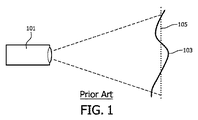
例えば、図1は、画像が非平面投影表面103上にプロジェクタ101により投影される例を例示する。図示されるように、プロジェクタ101は、画像平面105が幾つかのポイントで投影表面103と一致するように調整されるが、画像平面105が表面103と一致する、すなわち全ての点で表面103と一致することはできない。よって、実際の投影表面103は、画像平面105から逸脱し、従って、投影画像は焦点が合わず、表面103が画像平面105と一致する特定の領域を除いてシャープには見えない。よって、投影画像は、画像平面105と一致している表面103の部分でだけシャープに見える。表面103の他の部分では(画像平面105から逸脱している部分では)、画像は、非合焦のため、ぼやけて見える。結果として、画像の感知されるシャープさのかなりの損失が、観察者により感知される。
For example, FIG. 1 illustrates an example in which an image is projected by a
斯様な課題に対処するために、表面ジオメトリーを測定し、表面変動を補償できる適当なレンズを設計できる。しかしながら、このアプローチは、表面形状の小さなクラスでのみ可能で、高価であり、特定の取付け/表面に対するプロジェクタの適用を制限する。後者の課題に対処するために、レンズシステムを表面ジオメトリーに自動的に合わせる適応可能な光システムを使用できる。しかしながら、斯様な適応可能な光システムは、極めて高価であって、衛星アプリケーションでしかるべく用いられるが、例えば民生製品に対して適当ではない。 To address such challenges, a suitable lens can be designed that can measure surface geometry and compensate for surface variations. However, this approach is only possible with a small class of surface shapes, is expensive, and limits the projector's application to specific mounting / surfaces. To address the latter challenge, an adaptive light system can be used that automatically adapts the lens system to the surface geometry. However, such adaptable optical systems are very expensive and are used accordingly in satellite applications, but are not suitable for consumer products, for example.
他の例として、画像が動いているターゲットに投影されるとき、すなわち投影表面が移動するとき、従来のシステムは不利な点を持つ傾向がある。図2は、プロジェクタ201が、画像平面203に沿って動く可動表面203に画像を投影する例を例示する。しかしながら、表面203が画像平面と一致するにもかかわらず、表面203の動きは、結果的に、観察者により明らかに認識可能な動きぼやけになる。
As another example, conventional systems tend to have disadvantages when an image is projected onto a moving target, ie when the projection surface moves. FIG. 2 illustrates an example in which the
投影表面105の動きが充分に知られていて、画像平面に沿って単純な並進に限られている場合、動きぼやけは、可動表面をプロジェクタが追尾することにより補正される。更にまた、ターゲットの動きが充分に知られている場合、動きぼやけは、投影の前に画像のプリフィルタリングにより潜在的に補償される。プリフィルタは、動きから決定できる。しかしながら、多くのシナリオで、動きは、既知でないか、又は、実際的な追尾又は補償のためにはあまりにも複雑である。更にまた、動きぼやけは、実際に実行可能なフィルタにより補償できない周波数応答のゼロにより特徴づけられる傾向があるので、プリフィルタリングは画像歪みを導く傾向がある。
If the movement of the
更に別の例として、色収差、球面収差、非点収差により、結果的に減少したシャープさになる傾向がある。例えば、図3に図示されるように、色収差は、結果的に異なる色に対してわずかに異なる画像平面になり得るので、このことにより結果的に非焦点となり、よって、色の少なくとも1つに対してあまりシャープでない画像になる。同様に、図4に示されるように、球面収差は、結果としてレンズの光軸に沿った焦点の不鮮明さになり、このことにより焦点が合わなくなる。図5に図示されるように、非点レンズ収差は、わずかにカーブする画像平面を与える。画像が平坦面上に投影される場合、これは、結果的に部分的な画像非合焦になる。 As yet another example, chromatic aberration, spherical aberration, and astigmatism tend to result in reduced sharpness. For example, as illustrated in FIG. 3, chromatic aberration can result in slightly different image planes for different colors, which results in defocusing, and thus on at least one of the colors. On the other hand, the image is not very sharp. Similarly, as shown in FIG. 4, spherical aberration results in blurring of the focus along the optical axis of the lens, which causes it to become out of focus. As illustrated in FIG. 5, astigmatism gives a slightly curved image plane. If the image is projected on a flat surface, this results in partial image defocusing.
よって、改良された画像投影アプローチは有利であり、特に、増大された柔軟性、改良された知覚される画像鮮明度、減少した複雑さ、容易な実行及び/又は改良されたパフォーマンスを可能にするアプローチが有利である。 Thus, an improved image projection approach is advantageous, in particular allowing for increased flexibility, improved perceived image sharpness, reduced complexity, easy implementation and / or improved performance. The approach is advantageous.
従って、本発明は、好ましくは単独で又は組合せて、上述の不利な点の一つ以上を緩和し、軽減し、又は除去しようとする。 Accordingly, the present invention seeks to mitigate, reduce or eliminate one or more of the above-mentioned disadvantages, preferably alone or in combination.
本発明の一態様によると、対象物の表面上に画像を投影するための照明プロジェクタと、画像平面に画像を合焦させるための合焦手段と、前記表面に対して前記画像平面の位置を動的に変化させるためのコントローラと、前記照明プロジェクタによる投影の前に画像を前置補償するためのフィルタとを有する、画像投影装置が提供される。 According to one aspect of the present invention, an illumination projector for projecting an image on the surface of an object, focusing means for focusing the image on an image plane, and the position of the image plane with respect to the surface An image projection apparatus is provided having a controller for dynamically changing and a filter for precompensating an image prior to projection by the illumination projector.
本発明は、多くのシナリオ及び実施例において改良された画像投影を可能にする。特に、本発明は、多くのシナリオにおいて、低い複雑さを維持すると共に、改良された画像品質を提供する。 The present invention enables improved image projection in many scenarios and embodiments. In particular, the present invention maintains improved complexity and provides improved image quality in many scenarios.
例えば、本発明は、画像投影まで様々な距離を持つ表面上、特に非平面表面上での改良された画像投影を可能にする。本発明は、例えば、可動表面上の改良された画像投影を可能にするか、又は例えば、色収差、球面収差、若しくは非点収差による画像劣化を減らす。 For example, the present invention enables improved image projection on surfaces with varying distances to image projection, especially on non-planar surfaces. The present invention allows, for example, improved image projection on a movable surface or reduces image degradation due to, for example, chromatic aberration, spherical aberration, or astigmatism.
当該アプローチは、具体的には、表面の任意の所与のポイントで投影画像のぼやけ又は非合焦を導入する。しかしながら、このぼやけは、比較的正確に推定され/予測されて、更にまた、画像投影までの距離に相対的に独立している。よって、ぼやけの補償が容易になり、特に同じ補償が距離と独立して適用され、このことにより同じ補償が画像間で適用可能になる。従って、全体の改良された画像品質が達成される。 The approach specifically introduces blurring or defocusing of the projected image at any given point on the surface. However, this blur is estimated / predicted relatively accurately and is also relatively independent of the distance to the image projection. Thus, blur compensation is facilitated, and in particular, the same compensation is applied independently of distance, which allows the same compensation to be applied between images. Thus, overall improved image quality is achieved.
特に、画像平面の相対的な位置の動的な変化は、比較的予測可能で、表面と照明プロジェクタとの間の距離から比較的独立している投影画像を結果的にぼやけさせることになる。更にまた、ぼやけの効果は、適切な逆フィルタが実際に実行可能である比較的良好な反応を持つ。よって、フィルタは、画像平面の相対的な位置の変化により生じるぼやけの効果の逆フィルタに近くてもよく、このことにより、結果的に、表面上の投影画像が、よりシャープな画像を供給する。更にまた、シャープさの改良は、照明プロジェクタと表面との間の距離から比較的独立していて、このことにより、表面のジオメトリーについての知識なしにさえ、表面の全ての領域上に有効な補償を可能にする。従って、実質的に改良された画像品質が達成される。 In particular, dynamic changes in the relative position of the image plane are relatively predictable and result in blurring of the projected image that is relatively independent of the distance between the surface and the lighting projector. Furthermore, the blur effect has a relatively good response that a suitable inverse filter is actually feasible. Thus, the filter may be close to the inverse filter of the blur effect caused by the relative position change of the image plane, which results in the projected image on the surface providing a sharper image. . Furthermore, the sharpness improvement is relatively independent of the distance between the lighting projector and the surface, which makes effective compensation over all areas of the surface, even without knowledge of the surface geometry. Enable. Thus, substantially improved image quality is achieved.
前置補償は、具体的には、表面に対する画像平面の位置の変動により生じるぼやけ効果に対する補償である。 Pre-compensation is specifically compensation for blurring effects caused by variations in the position of the image plane relative to the surface.
制御手段は、照明プロジェクタ(例えば照明プロジェクタのレンズから測定される)から画像平面までの距離を動的に変化させるように調整される。よって、コントローラは、画像平面を動的に動かすために、照明プロジェクタの焦点合わせ特性を動的に調整する。幾つかの実施例では、コントローラは、例えばプロジェクタ若しくは対象物、又はそれらの両方を移動することにより、表面と照明プロジェクタとの間の距離を動的に変化させる。 The control means is adjusted to dynamically change the distance from the illumination projector (eg, measured from the lens of the illumination projector) to the image plane. Thus, the controller dynamically adjusts the focusing characteristics of the lighting projector in order to dynamically move the image plane. In some embodiments, the controller dynamically changes the distance between the surface and the lighting projector, for example by moving the projector and / or the object.
コントローラは、対象物に対する画像平面の位置を自動的に変化させる。コントローラは、表面に対する画像平面の位置の連続的変化を導入する。特に、画像平面は、表面に対して連続的に移動する。よって、幾つかの実施例では、画像平面は、表面に対して決して静的でない。変化はユーザー入力なしで発生し、実際、変化はユーザー入力から独立している。よって、手動ユーザー入力が受信されない場合でも、変化が導入される。コントローラは、表面に対して画像平面の位置に、ジッターを導入する。照明プロジェクタ又は表面の特性の変化が発生しない場合であっても、変化が発生する。特に、変化は、画像投影装置及び/又は表面/対象物の特性から独立している。 The controller automatically changes the position of the image plane relative to the object. The controller introduces a continuous change in the position of the image plane relative to the surface. In particular, the image plane moves continuously with respect to the surface. Thus, in some embodiments, the image plane is never static with respect to the surface. Changes occur without user input, and in fact, changes are independent of user input. Thus, changes are introduced even if no manual user input is received. The controller introduces jitter at a position in the image plane relative to the surface. Even if there is no change in the characteristics of the lighting projector or the surface, a change occurs. In particular, the change is independent of the characteristics of the image projection device and / or the surface / object.
画像平面は、投影画像が合焦している仮想平面である。 The image plane is a virtual plane on which the projection image is focused.
本発明のオプションの特徴によると、フィルタは、前記画像平面と前記表面との間の距離から独立している基準のぼやけ効果を前置補償するように配される。 According to an optional feature of the invention, the filter is arranged to precompensate for a reference blur effect that is independent of the distance between the image plane and the surface.
これは、多くの実施例において、低い複雑さを維持すると共に、改良された画像品質を提供する。特に、基準のぼやけ効果は、変化の関数として発生するぼやけに近い。基準のぼやけ効果は、種々異なる距離でのぼやけ効果の近似であり、具体的には、例えば異なる距離でのぼやけ効果の加重平均に対応する。よって、補償は、(距離に独立した)一定の基準のぼやけ効果の仮定に基づく。フィルタは、具体的には、基準のぼやけ効果の逆フィルタの近似である。 This provides improved image quality while maintaining low complexity in many embodiments. In particular, the reference blur effect is close to the blur that occurs as a function of change. The reference blur effect is an approximation of the blur effect at different distances, and specifically corresponds to, for example, a weighted average of blur effects at different distances. Thus, the compensation is based on a certain reference blur effect assumption (independent of distance). The filter is specifically an approximation of an inverse filter of the reference blur effect.
本発明のオプションの特徴によると、コントローラは、対象物に対する前記画像平面の位置に予め定められた変化を与えるように配される。 According to an optional feature of the invention, the controller is arranged to provide a predetermined change in the position of the image plane relative to the object.
これは、改良されたパフォーマンス、通常は感知される改良された画像品質、及び/又は容易な実行及び/又はオペレーションを提供する。 This provides improved performance, usually perceived improved image quality, and / or easy execution and / or operation.
本発明のオプションの特徴によると、コントローラは、前記表面に対する前記画像平面の位置に周期的変化を与えるように配される。 According to an optional feature of the invention, the controller is arranged to provide a periodic change in the position of the image plane relative to the surface.
これは、改良されたパフォーマンス、通常は感知される改良された画像品質、及び/又は容易な実行及び/又はオペレーションを提供する。 This provides improved performance, usually perceived improved image quality, and / or easy execution and / or operation.
本発明のオプションの特徴によると、前記周期的変化は、前記画像平面と前記表面上のポイントとの間の距離における三角形変化に対応する。 According to an optional feature of the invention, the periodic change corresponds to a triangular change in the distance between the image plane and a point on the surface.
これは、改良されたパフォーマンス、通常は感知される改良された画像品質、及び/又は容易な実行及び/又はオペレーションを提供する。当該特徴は、特に、ほとんどの実施例で非常に良好なパフォーマンスを提供する複雑さが低い実行を可能にする。 This provides improved performance, usually perceived improved image quality, and / or easy execution and / or operation. This feature in particular allows for low complexity execution that provides very good performance in most embodiments.
三角形変化は、(等しい上昇及び下降傾斜を持って)実質的に対称形でもよいし、又は非対称でもよい。特に、三角形変化は、1つの傾斜が他の傾斜の10%だけの期間を持つ実質的に鋸歯形状でもよい。 Triangular changes may be substantially symmetric (with equal rising and falling slopes) or asymmetric. In particular, the triangular change may be substantially serrated with one slope having a duration of only 10% of the other slope.
本発明のオプションの特徴によると、画像はビデオ信号のフレームであり、前記周期的変化がせいぜい2フレーム期間の期間を持つ。 According to an optional feature of the invention, the image is a frame of a video signal and the periodic change has a duration of at most two frame periods.
これは、特に有利なパフォーマンスを可能にし、特にビデオ画像シーケンスに対する改良された画像品質を可能にする。当該特徴は、特に、変化を可能にし、よって各フレームに対して実施されるべき補償等を可能にする。 This allows for particularly advantageous performance and in particular improved image quality for video image sequences. This feature makes it possible in particular to change, and thus to make compensation etc. to be performed for each frame.
幾つかの実施例では、周期的変化は、わずか1フレーム期間の期間を持つ。これは、特に有利なパフォーマンス、特に動いているコンテンツを持つフレームに対する画像品質を可能にする。 In some embodiments, the periodic change has a duration of only one frame period. This allows for particularly advantageous performance, especially image quality for frames with moving content.
幾つかの実施例では、周期的変化は、わずか500ミリ秒、100ミリ秒又は50ミリ秒の期間を持つ。 In some embodiments, the periodic change has a duration of only 500 milliseconds, 100 milliseconds, or 50 milliseconds.
本発明のオプションの特徴によると、コントローラは、前記照明プロジェクタの焦点を動的に変化させるように配される。 According to an optional feature of the invention, the controller is arranged to dynamically change the focus of the illumination projector.
これは、多くの実施例で、特に有利なオペレーション、パフォーマンス及び/又は実行を可能にする。特に、それは、様々な(未知の)非平面表面及び/又は(未知の)動き成分を持つ表面を含む多種多様な投影表面での使用に適しているフレキシブルな画像投影装置を可能にする。 This allows for particularly advantageous operation, performance and / or execution in many embodiments. In particular, it allows a flexible image projection device that is suitable for use on a wide variety of projection surfaces including various (unknown) non-planar surfaces and / or surfaces with (unknown) motion components.
本発明のオプションの特徴によると、コントローラは、前記表面の位置を動的に変化させるように配される。 According to an optional feature of the invention, the controller is arranged to dynamically change the position of the surface.
これは、多くの実施例において、特に有利なオペレーション、パフォーマンス及び/又は実行を可能にする。特に、これは、動的な自動化された焦点変化をサポートしない多くの照明プロジェクタとの改良された下位互換性を可能にする。 This allows particularly advantageous operation, performance and / or execution in many embodiments. In particular, this allows for improved backward compatibility with many lighting projectors that do not support dynamic automated focus changes.
本発明のオプションの特徴によると、コントローラは、前記画像投影装置から前記表面上のポイントまでの距離を、少なくとも前記画像投影装置から前記ポイントまでの最小距離だけ変化させるように配される。 According to an optional feature of the invention, the controller is arranged to change the distance from the image projection device to a point on the surface by at least a minimum distance from the image projection device to the point.
本発明は、改良されたパフォーマンス、通常は感知される改良された画像品質、及び/又は容易な実行及び/又はオペレーションを提供する。特に、当該アプローチは、表面までの距離について大きい変化を持って投影される画像の感知されるシャープさを提供する。 The present invention provides improved performance, usually perceived improved image quality, and / or easy execution and / or operation. In particular, the approach provides a perceived sharpness of the projected image with a large change in distance to the surface.
本発明のオプションの特徴によると、コントローラは、前記照明プロジェクタに最も近い前記表面の画像ポイントと前記照明プロジェクタから最も遠い前記表面の画像ポイントとの間の前記画像平面の位置に対して実質的に線形な動きを、前記表面に対する前記画像平面に供給するように配される。 According to an optional feature of the invention, the controller is substantially relative to the position of the image plane between the surface image point closest to the lighting projector and the surface image point furthest from the lighting projector. A linear motion is arranged to provide the image plane with respect to the surface.
これは、多くのシナリオで改良されたパフォーマンスを示す。特に、これは、均質の動きを可能にし、よって、全ての画像ポイントに対するぼやけの効果を可能にし、このことにより、結果的に同じ前置補償フィルタが全ての画像ポイントに対して適当となる。画像ポイントは、画像を呈示するために用いられる表面上のポイントである。画像ポイントは、表面の画像領域内の任意のポイントであり、当該画像領域は、画像が投影される表面の領域である。表面に対する画像平面の動きは、方向反転の間隔を除いて、その動き全体にわたって実質的に線形である。しかしながら、幾つかの実施例では、動きは、最も近い画像ポイントから最も遠い画像ポイントまでの間隔内で実質的に線形であるが、この間隔の外側の少なくとも幾らかの距離に対して非線形である。 This shows improved performance in many scenarios. In particular, this allows for a homogeneous movement and thus a blurring effect for all image points, so that the same pre-compensation filter is consequently suitable for all image points. An image point is a point on the surface used to present an image. An image point is an arbitrary point in an image area on the surface, and the image area is an area on the surface on which an image is projected. The motion of the image plane relative to the surface is substantially linear throughout the motion, except for the direction reversal interval. However, in some embodiments, the motion is substantially linear within the interval from the nearest image point to the farthest image point, but is non-linear for at least some distance outside this interval. .
本発明の別の態様によると、上述の画像投影装置及び対象物を有する画像投影システムが提供される。 According to another aspect of the present invention, there is provided an image projection system having the above-described image projection apparatus and object.
本発明は、改良されたパフォーマンス、通常は感知される改良された画像品質、及び/又は容易な実行及び/又はオペレーションを提供する。 The present invention provides improved performance, usually perceived improved image quality, and / or easy execution and / or operation.
本発明のオプションの特徴によると、前記表面は非平面表面である。 According to an optional feature of the invention, the surface is a non-planar surface.
本発明は、非平面表面への投影のための画像投影システムを提供する。 The present invention provides an image projection system for projection onto a non-planar surface.
本発明のオプションの特徴によると、画像投影システムは、前記表面を動かす手段を更に有し、動きは前記画像平面と直角をなす動き平面に動き成分を持つ。 According to an optional feature of the invention, the image projection system further comprises means for moving the surface, and the movement has a movement component in a movement plane perpendicular to the image plane.
本発明は、動く表面上への投影のための画像投影システムを提供する。 The present invention provides an image projection system for projection onto a moving surface.
本発明のオプションの特徴によると、システムは、フォトリソグラフィシステムである。 According to an optional feature of the invention, the system is a photolithography system.
本発明は、改良されたフォトリソグラフィシステムを提供する。 The present invention provides an improved photolithography system.
本発明の一態様によると、照明プロジェクタにより画像を対象物の表面に投影させるステップと、画像平面上に画像を合焦させるステップと、前記表面に対して前記画像平面の位置を動的に変化させるステップと、前記照明プロジェクタによる投影の前に、フィルタにより画像を前置補償するステップとを有する、画像投影の方法が提供される。 According to an aspect of the present invention, the step of projecting an image onto the surface of the object by the illumination projector, the step of focusing the image on the image plane, and the position of the image plane dynamically changing with respect to the surface And a method of image pre-compensation with a filter prior to projection by the illumination projector.
本発明のこれら及び他の態様、特徴及び利点は、これ以降説明される実施例を参照して、明らかに説明されるだろう。 These and other aspects, features and advantages of the present invention will be clearly described with reference to the examples described hereinafter.
本発明の実施例は、単なる例示として、図面を参照して説明されるだろう。 Embodiments of the present invention will be described by way of example only with reference to the drawings.
図6は、本発明の幾つかの実施例による画像投影システムの一例を示す。 FIG. 6 shows an example of an image projection system according to some embodiments of the present invention.
システムは、対象物の表面603に画像を投影するように配される画像投影装置601を有する。図6の具体例では、表面603は、(画像平面と直角をなす方向に沿った)具体例では画像投影装置601の主レンズの光軸に沿った画像投影装置601までの様々な距離を持つ非平面表面である。
The system has an
画像投影装置601は、対象物603の表面に画像を投影するように配される照明プロジェクタ605を有する。
The
画像投影装置601は、画像を画像平面607に合焦させるために照明プロジェクタ605を制御できる焦点調整装置609を特に有する。よって、照明プロジェクタ605は、画像平面607に投影画像を合焦させる。具体例では、照明プロジェクタ605は、投影画像を合焦させるレンズを有する。図7に示されるように、画像平面607は、このように、異なる位置でレンズ上に入射する同じ画像ポイントに対する全ての光が同じポイントで会う平面である。具体例では、焦点調整装置609は、焦点が所与の距離でシャープであるように、すなわち画像平面607が所与の距離にあるように、レンズと照明プロジェクタ605の光源との間の距離を制御する。他の実施例で、例えばレンズの制御された変形又は複数のレンズの位置の相対的な調整のような投影画像を合焦させるための他の手段が用いられてもよいことは理解されるだろう。
The
照明プロジェクタ605と表面603上の種々異なるポイントとの間の距離の変化は、かなり大きい。例えば、投影画像に対する画像平面と直角をなす方向の表面の変化は、画像プロジェクタ605から表面603までの平均距離に対応する距離で、投影画像領域のダイアゴナル(diagonal)の少なくとも10%である。
The change in distance between the
画像投影装置601は、更に、焦点調整装置609に結合される画像平面コントローラ611を有する。画像平面コントローラ611は、焦点調整装置609により実施される焦点調整を制御することにより画像平面607の位置を制御するように配される。画像平面コントローラ611は、表面603に対して画像平面607の位置を動的に変化させるように特に配される。図6の例では、画像平面607及び表面603の相対的な位置の動的な変化は、照明プロジェクタ605の焦点を変化させることにより達成されるが、他の実施例では、焦点は、代替的に又は追加的に、全体のプロジェクタ及び/又は表面607を動かすことにより達成されてもよいことは理解されるだろう。例えば、画像投影装置601は、所望の態様で全体のプロジェクタ/表面607を動かす外部モーターのための制御信号を生成するコントローラを有してもよい。
The
画像平面コントローラ611は、表面603に対する画像平面607、図6の例では照明プロジェクタ605に対する画像平面607の動的及び自動化された動きを導入するように配される(照明プロジェクタ605から表面603までの距離は、図1の例では一定である)。動きは、具体的には、画像の任意の特性及び/又は表面603の任意の特性から独立している相対的な動きである。特に、相対的な動きは、基準焦点上で導入されてもよい。例えば、ユーザは、所与の距離での画像平面607に結果としてなるように手動で焦点を調整してもよい。この基準距離上で、画像平面コントローラ611は、特に、基準画像平面距離からゼロの平均変位に結果としてなる動的な動きを更に導入する。
The
図6の例では、基準画像平面は、例えば手動ユーザフォーカスにより選択される。画像平面コントローラ611は、そのとき、画像平面607が、最も近い画像平面位置615から最も遠い画像平面位置617までの間隔613内で連続的に移動されるようにする焦点調整を導入する。よって、画像平面607は連続的に変化し、具体例では、変化の間隔613は非平面表面までの距離の変化より大きいように制御される。
In the example of FIG. 6, the reference image plane is selected by manual user focus, for example. The
従って、画像平面ジッター/動きは、照明プロジェクタ605までの所与の(固定の)距離にある表面607上の所与のポイントが、画像が完全に合焦される時点を経験するが、画像が合焦していない時点も経験するという効果を持つ。更にまた、この効果は、照明プロジェクタ605までの表面の正確な距離に関係なく、表面上の全てのポイントにより経験されるだろう。よって、従来のシステムで、非平面表面は幾つかのポイントでシャープな画像を持ち、他のポイントで合焦していないのに対し、現在のアプローチは、各ポイントがシャープな画像と合焦していない画像との組合せとして感知される合焦平均化された画像に結果としてなる。斯様なアプローチは、多くのシナリオにおいて、また多くのアプリケーションにおいて、結果的に画像の改良された良質な知覚になる。
Thus, image plane jitter / motion experiences a point in time when a given point on the
更にまた、発明者は、知覚できるほど最も重要なインパクトが、シャープである画像又は少しだけ焦点がずれた画像により供給されるので、当該アプローチは、特に有利であると理解した。よって、表面603上の所与のポイントに対して、そのポイントに対して知覚された画像の最も重要な寄与は、画像平面607がそのポイントと一致するときに提供される。画像平面607が表面ポイントと一致しないときの画像のインパクトは、画像平面607の増大している距離に対して減少する。よって、システムは、画像が合焦している時間の自動的加重を供給し、よって、非平面表面上の投影画像に対する改良された知覚された焦点を提供する。
Furthermore, the inventor has realized that this approach is particularly advantageous since the most perceptible impact is provided by a sharp or slightly defocused image. Thus, for a given point on the
実際、システムは、(画像平面が表面上のポイントと一致するときの)合焦している時点周辺の特定の時間間隔内での画像投影だけが重要である、投影画像のスナップショット効果を効果的に提供するように見える。例えば、非平面表面の変化は、画像平面607と直角をなす軸の方向に80cmである。変化間隔は、表面変化を上回って1mに設定されてもよい。斯様な実施例では、例えば、画像平面607が例えば±10cmの距離内にあるときだけ投影が視覚的に重要であり、更に離れた画像平面607を持つ投影のインパクトは無視できる(例えば、これらは充分にぼやけているので、これらは重要な画像コンテンツを提供しないからである)ということがわかる。この場合、各ポイントは、画像平面607が合焦内の[―10cm,10cm]の間隔内にあるとき、投影の結合された加重効果に対応する画像コンテンツを表すだろう。これは、照明プロジェクタ605に対するポイントの特定の距離に関係なく、表面603上の全てのポイントに対する場合である。
In fact, the system takes advantage of the projected image snapshot effect, where only image projection within a specific time interval around the point of focus (when the image plane coincides with a point on the surface) is important. Seem to provide. For example, the non-planar surface change is 80 cm in the direction of an axis perpendicular to the
発明者は、この効果が存在するだけでなく、非常に重要で、改良された画像呈示を提供するために都合よく使用できることも理解した。特に、発明者は、この効果の結果として、動いている画像平面から生じるぼやけの測定され知覚された効果が、照明プロジェクタ605までの表面上のポイントの実際の距離から比較的独立していることを理解した。換言すれば、表面上の全てのポイントは、画像の実質的に同じぼやけ及び歪みを経験する。発明者は、更にまた、全てのポイントが非常に同様のぼやけ効果を経験するので、これが同じ前置補償を適用することにより補償できると理解した。よって、特定のポイントと独立して、同じ前置補償が、画像品質を改善し、ぼやけ効果を補償するために使用できる。更にまた、発明者は、動いている画像平面により生じるぼやけ効果が数値的に行儀よく振る舞う傾向があり、画像平面の動きにより供給されるぼやけ効果を補償できる大幅に限定された領域を持つ比較的正確な逆フィルタが実行可能である傾向があると理解した。
The inventor has also realized that this effect is not only present, but is very important and can be conveniently used to provide improved image presentation. In particular, the inventor found that as a result of this effect, the measured and perceived effect of blurring resulting from the moving image plane is relatively independent of the actual distance of the point on the surface to the
よって、説明されるシステムの非常に有利な効果は、既知のシステムからの表面/距離依存のぼやけ/焦点ずれ効果を、個々のポイントの距離から独立している、よって特定の表面ジオメトリーから独立しているとみなされ得るぼやけ効果へ変換することである。よって、ぼやけ効果は、実際の距離及び正確なぼやけ効果に関係なく、表面上の各ポイントに対する基準ぼやけ効果に等しいとみなされることができる。換言すれば、基準の(固定した)ぼやけ効果(すなわち特定のポイント/距離から独立している)は、特定のポイント/距離に対する正確なぼやけ効果の十分に近い近似として使用できる。 Thus, a very advantageous effect of the described system is that surface / distance dependent blur / defocus effects from known systems are independent of the distance of the individual points and thus independent of the specific surface geometry. To a blur effect that can be considered to be. Thus, the blur effect can be considered equal to the reference blur effect for each point on the surface, regardless of the actual distance and the exact blur effect. In other words, the reference (fixed) blur effect (ie independent of a specific point / distance) can be used as a close enough approximation of the exact blur effect for a specific point / distance.
従って、前置補償は、画像が投影される特定の表面についての特定の知識又は詳細な知識を必要とせずに(例えば、動き間隔が表面変化より(適切なマージンだけ)大きいことをただ保証することにより)実施できる。よって、当該アプローチは、表面のための何れの知識、測定又は較正を必要とすることなく、多種多様な表面で使用できる。よって、大幅にフレキシブルで実用的な画像投影システムが達成できる。 Thus, pre-compensation does not require specific knowledge or detailed knowledge about the specific surface on which the image is projected (eg, it simply ensures that the motion interval is greater than the surface change (by an appropriate margin)). Can be implemented. Thus, the approach can be used on a wide variety of surfaces without requiring any knowledge, measurement or calibration for the surface. Thus, a significantly flexible and practical image projection system can be achieved.
よって、画像投影装置601は、投影されるべき画像を受信し、投影される前に画像の前置フィルタリングを実施するプリフィルタ619を有する。プリフィルタ619は、画像平面の動きにより生じるぼやけの効果を反映するぼやけカーネル(基準ぼやけ効果)を最初に決定することにより制御される。このぼやけカーネルは、具体的には、動いている画像平面の効果に対応する空間フィルタ応答として特徴づけられる。前述されたように、このぼやけカーネルは、実際の距離から独立しているとみなされ、よって、画像の全てのポイントに対して同じであるとみなされる。従って、プリフィルタは、ぼやけカーネルの逆フィルタの近似として決定される。
Thus, the
特に、ぼやけカーネル(表面に対する画像平面の動きにより生じたぼやけ効果)は、基準距離での平坦面と画像平面との異なる相対的位置に対応するぼやけカーネルを平均化する/積分することにより決定される。 In particular, the blur kernel (the blur effect caused by the movement of the image plane relative to the surface) is determined by averaging / integrating the blur kernel corresponding to different relative positions of the flat surface and the image plane at the reference distance. The
レンズ及び照明される対象物平面からなる簡略化された投影システムを考える。光システムの幾何学的なパラメータは、レンズアパーチャa、レンズの焦点距離f及び対象物平面とレンズとの間の距離xである。プロジェクタは、レンズの向こう側からの距離yでの画像平面で、対象物平面からの光を合焦させる。ここで、x、y、及びfはレンズの公式から以下の関係がある。
1/x+1/y=1/f
Consider a simplified projection system consisting of a lens and an illuminated object plane. The geometric parameters of the optical system are the lens aperture a, the focal length f of the lens and the distance x between the object plane and the lens. The projector focuses the light from the object plane on the image plane at a distance y from the other side of the lens. Here, x, y, and f have the following relationship from the lens formula.
1 / x + 1 / y = 1 / f
表面までの距離Lがyと異なる場合、そのとき対象物は、ぼやけて見える。合理的な仮定の下、ぼやけた画像は、画像平面と表面との間の距離|y−L|と乗算され、画像平面とレンズとの間の距離yで割られるレンズアパーチャと比例した半径(分散)bimg、すなわち、
bimg=|y−L|(a/y)
を持つガウスカーネル又はディスクと畳み込まれる(L=yで得られる)シャープな画像としてモデル化できる。
If the distance L to the surface is different from y, then the object looks blurry. Under reasonable assumptions, the blurred image is multiplied by the distance | y−L | between the image plane and the surface and is proportional to the lens aperture radius (divided by the distance y between the image plane and the lens) ( Variance) b img , ie
b img = | y−L | (a / y)
Can be modeled as a sharp image convolved with a Gaussian kernel or disk (obtained with L = y).
これは、光源801が拡散器803を照射し、その後オブジェクト平面805を照明する図8に示される。オブジェクト平面805からの光は、レンズ809により画像平面807上に合焦される。この例では、画像平面807は、画像が投影される平面の表面811と一致していない。
This is shown in FIG. 8 where the light source 801 illuminates the
動いている画像平面を持つシステムが表面上にぼやけ効果を発生するにもかかわらず、この効果に対する補償が、レンズの反対側、すなわち、プロジェクタ内部で、オブジェクト平面に適用されるべきである点に留意されたい。よって、ぼやけ効果を量子化し、適当な補償を定めるために、オブジェクト平面上に等価のぼやけの補助的イメージが、導入される。等価のぼやけは、同じぼやけ効果が予めぼやけた画像のシャープに合焦された投影により達成できるように定められる。 Even though a system with a moving image plane produces a blur effect on the surface, compensation for this effect should be applied to the object plane on the opposite side of the lens, i.e. inside the projector. Please keep in mind. Thus, in order to quantize the blur effect and define the appropriate compensation, an equivalent blur auxiliary image is introduced on the object plane. Equivalent blur is defined such that the same blur effect can be achieved by a sharply focused projection of a previously blurred image.
半径(分散)bimgを持つ表面上の画像のぼやけは、半径(分散)bobjを持つカーネルでぼやける対象物平面のシャープに合焦された投影に等しく、ここで、bobj及びbimgは、光学系のスケーリング比率、すなわち、
bobj=bimg(x/y)=|y−L|(ax/y2)
を介した関係がある。
The blur of the image on the surface with radius (dispersion) b img is equal to the sharply focused projection of the object plane blurring with the kernel with radius (dispersion) b obj , where b obj and b img are The scaling ratio of the optical system, i.e.
b obj = b img (x / y) = | y−L | (ax / y 2 )
There is a relationship through.
具体例では、光学系のパラメータは、表面に対する画像平面の動きが線形に近いように制御され、よって、等価のぼやけ半径も線形態様で、すなわち、
bobj=bobj(t)=vblur・|t−t0|
で変化し、
ここで、t0は図9に図示されたように、画像平面が表面と一致する時点である。光学系の必要な制御は、単一のパラメータx、f又はLの制御に単純化できる。例示的実行では、x及びLを不変にしたまま、画像平面が表面と一致するx0を通じて対象物平面が、ほぼ線形に進むことができ、すなわち、
x=x(t)≒x0+Vx・(t−t0)
であって、ここで、x0、L及びfがレンズ公式
1/x0+1/L=1/f
を介した関係にある。
In a specific example, the parameters of the optical system are controlled so that the motion of the image plane relative to the surface is close to linear, so the equivalent blur radius is also in a linear fashion, i.e.
b obj = b obj (t) = v blur · | t−t 0 |
Change in
Here, t 0 is the time when the image plane coincides with the surface, as shown in FIG. The necessary control of the optical system can be simplified to control of a single parameter x, f or L. In an exemplary implementation, the object plane can travel approximately linearly through x 0 where the image plane coincides with the surface, leaving x and L unchanged, ie,
x = x (t) ≈x 0 + V x · (t−t 0 )
Where x 0 , L and f are the
There is a relationship through.
この場合、等価のぼやけ半径は、ほぼ線形態様で、すなわち、以下の式のように変化することが分かる。

他の例示的実行では、x及びLを不変にしたまま、画像平面が表面と一致するf0を通じて焦点距離が、ほぼ線形に進むことができ、すなわち、
f=f(t)=f0+Vf・(t−t0)
であって、ここで、x、L及びf0がレンズ公式
1/x+1/L=1/f0
を介した関係にある。
In another exemplary implementation, leaving x and L unchanged, the focal length can proceed approximately linearly through f 0 where the image plane coincides with the surface, ie
f = f (t) = f 0 + V f · (t−t 0 )
Where x, L and f 0 are the
There is a relationship through.
この場合、等価のぼやけ半径は、ほぼ線形態様で、すなわち、以下の式のように変化することが分かる。
他の例示的実行では、x及びfを不変にしたまま、レンズと表面との間の距離が画像平面y0を通じてほぼ線形に変化でき、すなわち、
L=L(t)=y0+VL・(t−t0)
であって、ここで、x、y0及びfがレンズ公式
1/x+1/y0=1/f
を介した関係にある。
In another exemplary implementation, the distance between the lens and the surface can vary approximately linearly through the image plane y 0 while leaving x and f unchanged, ie
L = L (t) = y 0 + V L · (t−t 0 )
Where x, y 0 and f are the
There is a relationship through.
この場合、等価のぼやけ半径は、ほぼ線形態様で、すなわち、以下の式のように変化することが分かる。
もちろん、他の可能な実行もあり、例えば、ぼやけ半径の線形変化に近いものを生じさせる線形態様に近いやり方で、画像平面が表面を通過させるようにするために、x、f及びLの任意の組み合わせを変化できる。すなわち、
更に、ぼやけ半径/分散に対応する個別のぼやけカーネルbobj(t)が既知であると仮定する。これらが既知でない場合、ディスクカーネル
個別のぼやけカーネルを与えると、等価なシステムぼやけカーネルは、
![]()
![]()
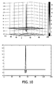
上記式を使用して、等価なシステムぼやけカーネルの数字的近似を計算できる。図9は、システムぼやけカーネルの例の実例を含む。 Using the above equation, a numerical approximation of the equivalent system blur kernel can be calculated. FIG. 9 includes an illustration of an example system blur kernel.
ぼやけカーネルの決定の後、補償のための対応する空間プリフィルタは、システムぼやけカーネルKsystem(x,y)のため逆フィルタに対する数字的近似により計算される。 After determination of the blur kernel, the corresponding spatial prefilter for compensation is calculated by numerical approximation to the inverse filter for the system blur kernel K system (x, y).
発明者は、システムぼやけカーネルが個別のぼやけカーネルの平均である一方、その周波数応答が全く異なることも理解した。個別のぼやけカーネルは、ゼロ周辺で全く平坦であり、従って、これらは周波数応答でよくゼロを出した。よって、個別のカーネルの反転(逆関数)が、不明確な課題である。しかしながら、個別のカーネルとは対照的に、システムぼやけカーネルは、ゼロで非常にシャープなピークを持ち、従って、コンパクトなサポートを持つ良く規定された反転に結果としてなる。図10は、ゼロ周辺の2、3のポイントに実際に限定されたサポートを持つ例示的逆カーネルを示す。このように、非常に実際的且つ効果的な前置補償が達成できる。 The inventor has also realized that while the system blur kernel is the average of the individual blur kernels, its frequency response is quite different. The individual blur kernels are quite flat around zero, so they well zeroed out in frequency response. Thus, the inversion (inverse function) of individual kernels is an unclear issue. However, in contrast to individual kernels, the system blur kernel has a very sharp peak at zero, thus resulting in a well-defined inversion with compact support. FIG. 10 shows an exemplary inverse kernel with support actually limited to a few points around zero. In this way, very practical and effective precompensation can be achieved.
説明されているアプローチは、このように非平面表面上の画像の実質的に改良された投影を提供する。実際、表面に対する画像平面の動きは、投影画像を改良するだけでなく、全ての距離(従って表面上のポイント)に対して予測可能であり比較的一定でもあるぼやけ効果を供給する。よって、動いている画像平面により生じるぼやけ効果は、距離と独立して一様に補償できる予測可能な効果を供給し、これにより、表面上の個々のポイントまでの多種多様な距離に対して、よりシャープな画像を供給する。よって、これは、表面の特定の特性とは無関係に、特に表面の特定の形状及びジオメトリーとは無関係に達成される。 The described approach thus provides a substantially improved projection of the image on the non-planar surface. In fact, the movement of the image plane relative to the surface not only improves the projected image, but also provides a blur effect that is predictable and relatively constant for all distances (and thus points on the surface). Thus, the blur effect caused by a moving image plane provides a predictable effect that can be uniformly compensated independently of the distance, thereby allowing for a wide variety of distances to individual points on the surface, Provide sharper images. This is thus achieved independently of the specific properties of the surface, in particular independent of the specific shape and geometry of the surface.
例えば、より暗い領域が固定の画像平面と表面上のポイントとの間の減少している距離を示す図12により与えられるような形状を持つ特定の非平面表面に図11のテストパターンが投射されてもよい。図13は、従来の固定の画像平面を使用して結果として生じる画像を例示し、図14は、ぼやけ効果の補償のための適切なプリフィルタと共に動いている画像平面を使用して得られる結果を例示する。図示されているように、動いている画像平面を用いたアプローチは、高周波のより正確な再生を可能にする。 For example, the test pattern of FIG. 11 is projected onto a particular non-planar surface having a shape as given by FIG. 12 where the darker areas indicate a decreasing distance between a fixed image plane and a point on the surface. May be. FIG. 13 illustrates the resulting image using a conventional fixed image plane, and FIG. 14 shows the result obtained using the moving image plane with an appropriate prefilter for blur effect compensation. Is illustrated. As shown, the moving image plane approach allows for more accurate reproduction of high frequencies.
他の例では、図15の画像は、図12により与えられるような形状を持つ表面に投影される。図16は、従来の一定の画像平面を使用して結果として生じる画像を例示し、図17は、プリフィルタリングなしで、動いている画像平面だけを使用して得られる結果を例示し、図18は、動いている画像平面を使用し、ぼやけ効果の補償のための適切なプリフィルタで得られる結果を例示する。図示されているように、図17は、図16の品質を越えて大幅に改良され、より均質の画質を示し、図18は、図16及び図17を越えた優れた品質を示す。特に、当該アプローチは、従来技術でシャープな領域のシャープさを維持しながら、従来技術で高い程度でのぼやけを経験する領域において達成できるシャープさを大幅に改善することが分かる。 In another example, the image of FIG. 15 is projected onto a surface having a shape as given by FIG. FIG. 16 illustrates the resulting image using a conventional constant image plane, FIG. 17 illustrates the result obtained using only the moving image plane without pre-filtering, and FIG. Illustrates the results obtained with a suitable pre-filter for compensation of blur effects using moving image planes. As shown, FIG. 17 is a significant improvement over the quality of FIG. 16 and shows a more uniform image quality, and FIG. 18 shows the superior quality over FIGS. In particular, it can be seen that this approach significantly improves the sharpness that can be achieved in regions that experience a high degree of blur in the prior art while maintaining sharpness in sharp regions in the prior art.
理想的な前置補償フィルタが必ずしも適用できるとは限らないことは理解されるだろう。実際、多くの実施例では、斯様なアプローチは、表面上の他のポイントからのぼやけている光を相殺できる「負の」照明を生成することを前置補償フィルタに要求する。これは、結果的に、シャープに合焦された投影と比較する場合、投影画像の低減されたコントラストとして知覚される幾つかのクリッピング偽信号になる。低減されたコントラストは、大部分は非常に暗いか非常に明るい領域において、更に、シャープな画像の縁近傍で観察される。しかしながら、説明されたアプローチの利点は、画像平面の動きから生じるぼやけカーネルが数値的に非常に良好な振る舞いをする傾向があるので、従って近似の逆フィルタにより前置補償されるのに良く適しているということである。特に、実際のシステムで起こるぼやけカーネルは、周波数領域においてほとんどゼロを持たない傾向があるので、従って逆フィルタに対して結果的に特異点にならない傾向がある。 It will be understood that an ideal pre-compensation filter is not always applicable. In fact, in many embodiments, such an approach requires the pre-compensation filter to produce “negative” illumination that can cancel out blurry light from other points on the surface. This results in several clipping spurious signals that are perceived as reduced contrast in the projected image when compared to a sharply focused projection. Reduced contrast is observed mostly in very dark or very bright areas, and near the edges of sharp images. However, the advantage of the described approach is that the blur kernel resulting from the motion of the image plane tends to behave very well numerically and is therefore well suited to be precompensated by an approximate inverse filter. That is. In particular, blur kernels that occur in real systems tend to have few zeros in the frequency domain, and therefore tend not to be singularities as a result for the inverse filter.
表面に対する画像平面の異なる動きが異なる実施例で使用されることは理解されるだろう。実際、上述されたように、ぼやけ効果は、画像平面が表面上の特定のポイント近くにあるときの時間によりほとんど支配される傾向があるので、従って、ぼやけ効果は動きから比較的独立している。 It will be appreciated that different movements of the image plane relative to the surface are used in different embodiments. In fact, as mentioned above, the blur effect tends to be mostly dominated by the time when the image plane is near a certain point on the surface, and therefore the blur effect is relatively independent of motion. .
しかしながら、多くの実施例では、画像平面が表面上のポイントの所与の距離の範囲内にあるとき、表面に対する画像平面の動きが実質的に同じことであるように、動きを制御することにより、改良されたパフォーマンスが達成される。よって、画像が呈示される表面の領域内の全てのポイントは、画像平面がポイントの近くにあるとき、同じ動きを実質的に経験する。これは、具体的には、最も近いポイント及び最も遠いポイントに関しておそらく充分なマージンがあるくらいの表面上の全てのポイントを含む間隔内で、動きが実質的に線形であることを保証することにより達成される。所与の距離は、例えば(光放射のポイントで測定される)照明プロジェクタから変化の間隔の中間点までの距離の1/10である。別の例として、所与の距離は、単に例えば10cm又は50cmである。 However, in many embodiments, by controlling the movement so that when the image plane is within a given distance of a point on the surface, the movement of the image plane relative to the surface is substantially the same. Improved performance is achieved. Thus, all points within the area of the surface on which the image is presented experience substantially the same movement when the image plane is near the point. This is specifically by ensuring that the motion is substantially linear within an interval that includes all points on the surface such that there is probably enough margin for the nearest and farthest points. Achieved. The given distance is, for example, 1/10 of the distance from the lighting projector (measured at the point of light emission) to the midpoint of the change interval. As another example, the given distance is simply 10 cm or 50 cm, for example.
動きは、特に、表面及び画像平面の相対的な位置の予め定められた変化を使用する。予め定められた変化の使用によって、ぼやけカーネルが予め定められ、よってプリフィルタが設計フェーズの段階で予め決定可能である。よって、当該アプローチは、実行及び/又はオペレーションを容易にし、このように特定のアプリケーション及び使用するシナリオに対する較正又は適応を回避する。 The movement uses in particular a predetermined change in the relative position of the surface and the image plane. By using a predetermined change, the blur kernel is predetermined, so that the prefilter can be predetermined in the design phase. Thus, this approach facilitates execution and / or operation, thus avoiding calibration or adaptation for the particular application and scenario used.
動きの振幅は、具体的には、プロジェクタから非平面表面までの距離の変化より、例えば少なくとも20%、30%、50%又は100%大きい。 Specifically, the amplitude of motion is at least 20%, 30%, 50% or 100% greater than the change in distance from the projector to the non-planar surface, for example.
多くの実施例では、動きは、具体的には、一方の動きとそれに続く反対方向の動きとの間を交番する三角形変化のような周期的変化である。各方向の動きは、線形動きである。(画像平面とポイントとの一致点の周りの間隔内で)表面上の異なるポイントに対して同一である対称形の動きに結果としてなるので、斯様な動きは特に有利である。 In many embodiments, the movement is specifically a periodic change, such as a triangular change that alternates between one movement followed by a movement in the opposite direction. The movement in each direction is a linear movement. Such movement is particularly advantageous because it results in a symmetrical movement that is identical for different points on the surface (within an interval around the coincidence of the image plane and the point).
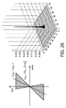
図19は、表面に対して画像平面の三角形動きの2つの例を例示する。 FIG. 19 illustrates two examples of triangular motion of the image plane relative to the surface.
図19は、特に、2つの方向の動きが実質的に対称形である(すなわち一方向の動きの速度がほぼ他方向の速度とほぼ同じである)例を例示する。これは、特に、投影画像が比較的変化しない多くのシナリオにおいて有利である。特に、対称形の動きが比較的単純な手段により達成できるので、これは実行を容易にする傾向がある。 FIG. 19 specifically illustrates an example in which the movement in two directions is substantially symmetric (ie, the speed of movement in one direction is substantially the same as the speed in the other direction). This is particularly advantageous in many scenarios where the projected image is relatively unchanged. In particular, this tends to be easy to implement, since symmetrical movements can be achieved by relatively simple means.
図19は、また、2つの方向の動きが非対称である、すなわち一方向の動きの速度が他方向の速度より非常に高い例を例示する。これは、特に、多くの動きがあるコンテンツで投影画像が比較的に動的である多くのシナリオにおいて有利である。特に、前述されたように、所与のポイントに対する画像のインパクトは、画像平面がポイントと一致する時間の周りに集中される。よって、効果的に、所与のポイントに対する画像は、一致時間の周りの短い時間間隔での画像により表されると考えられる。よって、画像は、一致の時間で比較的短い画像「フラッシュ」により生成されると、直観的に考えられる。更にまた、「フラッシュ」の時間は、特定のポイントの位置に依存し、画像平面が一致する時に依存する。よって、動き間隔の中央位置と一致しているポイントに対して、規則的な「フラッシュ」パターンが達成されるように、「フラッシュ」は(時間的に)等距離である。しかしながら、対称形の動きのために、中央位置から離れたポイントに対する「フラッシュ」は、等距離ではなく、短い時間間隔と長い時間間隔との間を交番する傾向がある。移動物体に対して、これは、認識できるほどのフリッカ効果として知覚される。しかしながら、この効果は、(特に実質的に鋸歯形状である)非対称のパターンを用いて緩和される。特に、画像は一方向の動きにより支配され、このことにより、結果的により等距離の「フラッシュ」になる(フラッシュが効果的に一方向の動きに対してのみ発生するので)。 FIG. 19 also illustrates an example in which the motion in the two directions is asymmetric, i.e. the speed of the motion in one direction is much higher than the speed in the other direction. This is particularly advantageous in many scenarios where the projected image is relatively dynamic with content with a lot of movement. In particular, as described above, the impact of an image on a given point is concentrated around the time that the image plane coincides with the point. Thus, effectively, the image for a given point is considered to be represented by images at short time intervals around the coincidence time. Thus, it is intuitively assumed that an image is generated by a relatively short image “flash” with a matching time. Furthermore, the “flash” time depends on the position of the particular point and when the image planes coincide. Thus, “flash” is equidistant (in time) so that a regular “flash” pattern is achieved for points that coincide with the center position of the motion interval. However, due to the symmetrical movement, the “flash” for points away from the central position tends to alternate between short and long time intervals rather than equidistant. For moving objects, this is perceived as an appreciable flicker effect. However, this effect is mitigated using an asymmetric pattern (especially substantially serrated). In particular, the image is dominated by movement in one direction, which results in a more equidistant “flash” (since flash effectively occurs only for movement in one direction).
移動物体の投影を改良するために、特定の方向の画像平面の動きの間だけ、プロジェクタを照明することができる。しかしながら、このアプローチは、プロジェクタの照明効率の低減を引き起こす。特定の方向に遅い動きの間に光が主に投影され、その後、画像平面の戻り動きの間、光が低減されるか完全に切られる画像平面の非対称の動きを使用して、照明効率の低下は最小にできる。発明者は、また、画像平面の変位が鋸歯パターンに従う極端な場合がプロジェクタの照明効率の低減を引き起こさないことに気付いている。 In order to improve the projection of moving objects, the projector can be illuminated only during the movement of the image plane in a particular direction. However, this approach causes a reduction in projector illumination efficiency. Using an asymmetrical movement of the image plane where light is mainly projected during slow movement in a particular direction and then light is reduced or completely cut off during the return movement of the image plane. The decline can be minimized. The inventor has also realized that extreme cases where the displacement of the image plane follows a sawtooth pattern does not cause a reduction in the illumination efficiency of the projector.
画像が、動いている画像(ビデオ信号)シーケンスの画像/フレームである場合、周期的変化は、せいぜい2フレーム期間を持つ。実際、多くの実施例では、期間は、実質的に2フレームに設定される。これはビデオ信号の非常に有利なプレゼンテーションを提供し、特に、各フレームが表面上の各ポイントにより少なくとも一度呈示されるように、画像平面の動きがフレームレートに適応可能にする(例えば同期可能にする)。例えば、対称形の三角形形状のために、動きの各方向は、各フレームが表面上のポイントに対して一度呈示されるように、フレームに対応して同期される。 If the image is an image / frame of a moving image (video signal) sequence, the periodic change has at most 2 frame periods. In fact, in many embodiments, the period is set to substantially two frames. This provides a very advantageous presentation of the video signal, in particular allowing the motion of the image plane to adapt to the frame rate (e.g. to be synchronizable) so that each frame is presented at least once by each point on the surface. To do). For example, because of the symmetrical triangular shape, each direction of motion is synchronized corresponding to a frame so that each frame is presented once to a point on the surface.
幾つかの実施例では、周期的変化は、好適にもせいぜい1フレーム期間の期間を持つ。これは、各フレームが両方向の十分な動きによりカバーされることを可能にする。これは、例えば、各フレームが表面上の各ポイントにより二度「フラッシュ」可能にする。実際、図19の非対称の鋸歯の例に対して、斯様なアプローチは、速い動きの時間間隔に依存することなく、各フレームの適切な呈示を保証する。 In some embodiments, the periodic change preferably has a duration of at most one frame period. This allows each frame to be covered with sufficient movement in both directions. This allows, for example, each frame to be “flashed” twice by each point on the surface. In fact, for the asymmetric sawtooth example of FIG. 19, such an approach ensures proper presentation of each frame without relying on fast motion time intervals.
多くの実施例において、周期的な動きは、非常に速い。実際、静的画像に対してさえ、0.5秒未満、100msec又は50msecの期間が、多くのシナリオで非常に有利なパフォーマンスを提供する。特に、人間の知覚が画像平面の異なる位置から単一の画像に光を結合するには十分に速く、これにより、実質的に距離とは無関係に、平均化され均一なぼやけ効果を供給する。 In many embodiments, the periodic movement is very fast. In fact, even for static images, periods of less than 0.5 seconds, 100 msec, or 50 msec provide very advantageous performance in many scenarios. In particular, human perception is fast enough to combine light from different positions in the image plane into a single image, thereby providing an averaged and uniform blur effect, substantially independent of distance.
動きは、更にまた、非常に大きくてもよい。実際、多くの実施例では、画像投影装置は、画像投影装置から表面上のポイントまでの少なくとも最小距離だけ、画像投影装置から表面上のポイントまでの距離を変化させるように配される。よって、ポイントに対する変化は、表面上のポイントまでの最小距離以上である。当該ポイントは、具体的には、画像投影装置までの最短距離を持つポイントである。よって、説明されているアプローチは、表面までの距離について非常に大きい変化を可能にし、依然高品質画像投影を提供する一方、このように平坦面からの非常に高い偏差を可能にする。 The movement may also be very large. Indeed, in many embodiments, the image projection device is arranged to vary the distance from the image projection device to the point on the surface by at least a minimum distance from the image projection device to the point on the surface. Thus, the change to the point is greater than or equal to the minimum distance to the point on the surface. Specifically, the point is a point having the shortest distance to the image projector. Thus, the approach described allows for very large changes in the distance to the surface and still provides a high quality image projection while thus allowing a very high deviation from a flat surface.
画像投影装置から(例えば図6の基準615に対応する)ポイントまでの最小距離は、ほぼ1mであり、(例えば図6の基準617と615との間の差、すなわち間隔613に対応する)変化間隔は2mである。これは、例えば照明プロジェクタ605から1.3〜2.8メートルの表面上のポイントまでの距離に対して比較的シャープな画像に結果としてなる。
The minimum distance from the image projection device to the point (eg corresponding to the
前の例は、画像投影装置の焦点が画像平面を動くために動的に変えられる実施例に焦点を当てていた。しかしながら、代替的に又は追加的に、画像平面と表面との相対的な動きが、表面の動きを導入することにより、すなわち対象物を動かすことにより達成されることは理解されるだろう。この動きは、画像平面と直角をなす、すなわち図6の例の画像投影装置の方へ向かって、又は離れる動き平面の動き成分を持つ。 The previous example focused on an embodiment in which the focus of the image projector was changed dynamically to move the image plane. However, it will be appreciated that alternatively or additionally the relative movement of the image plane and the surface is achieved by introducing the movement of the surface, i.e. by moving the object. This motion has a motion component of a motion plane that is perpendicular to the image plane, ie towards or away from the image projection device of the example of FIG.
前の説明は、また、画像が非平面表面に投影されるアプリケーションに焦点を当てていた。しかしながら、アプローチが他の実施例に使用されてもよいことは理解されるだろう。 The previous description has also focused on applications where images are projected onto non-planar surfaces. However, it will be appreciated that the approach may be used for other embodiments.
(例えば、照明プロジェクタ605の焦点を修正することによる)画像平面の相対的な動きは、例えば、レンズが球面収差、色収差又は非点収差を持つシステムの改良された画像品質を提供するために用いられてもよい。実際、斯様な収差は、画像平面までの距離の変化により(異なる色のために、又はレンズを通る異なる光経路のために)発生し、画像平面の連続的動きは、斯様な感度をしかるべく緩和する。しかしながら、色収差の場合、投影カラーチャネルは、わずかに異なるスケーリング比率を持つ。実際、レンズと対象物面との間の距離がシャープに動く間、レンズと表面との間の距離とレンズの焦点距離との両方がほぼ同じである場合、異なるカラーチャネルに対する投影画像は、レンズと対象物面との間の異なる距離に対応し、これは異なるスケーリング比率に対応する。従って、互いに投影される異なるカラーチャネルに対応する画像を持つために、アプローチは、投影の前に、画像の異なるカラー成分のプリスケールを使用する。よって、幾つかの実施例では、システムは、あるカラーチャネルを他のカラーチャネルに対してプリスケールするための手段を有する。 The relative movement of the image plane (eg, by modifying the focus of the illumination projector 605) is used, for example, to provide improved image quality in systems where the lens has spherical aberration, chromatic aberration or astigmatism. May be. In fact, such aberrations are caused by changes in the distance to the image plane (for different colors or for different light paths through the lens), and the continuous movement of the image plane results in such sensitivity. Relax as appropriate. However, in the case of chromatic aberration, the projected color channel has a slightly different scaling ratio. In fact, while the distance between the lens and the object surface moves sharply, if both the distance between the lens and the surface and the focal length of the lens are approximately the same, the projected image for the different color channels is Corresponding to different distances between the object plane and the object plane, which correspond to different scaling ratios. Thus, in order to have images corresponding to different color channels projected to each other, the approach uses a prescale of different color components of the image before projection. Thus, in some embodiments, the system has means for pre-scaling one color channel relative to another color channel.
所与のカラーチャネルに対して、スケーリングの量は、所与の色に対するレンズの実効的な実際の長さに比例し、実際の焦点距離で小さくなるレンズとプロジェクタとの間の距離に反比例するように設定できる。 For a given color channel, the amount of scaling is proportional to the effective actual length of the lens for a given color and inversely proportional to the distance between the lens and the projector, which decreases at the actual focal length. Can be set as follows.
例えば、3つのカラーチャネルを持つシステムでは、3つのカラーに対する実際の焦点距離は、f1、f2及びf3であり、レンズと表面との間の距離はLである。このとき、スケーリングされてない画像の第1のカラー成分を残して、第2及び第3のカラー成分を以下の因子でスケーリングできる。
画像平面の動きは、また、プロジェクタのスケーリング比率に影響を及ぼすことなく、多くの他の態様で達成できる。この場合、異なるカラーチャネルの前置スケーリングは必要でなく、球面収差も良好に積分され、結果的に全体のより良好な画像品質となる。例えば、画像平面の動きは、表面までの距離と対象物面までの距離との間の比率を略同じに維持したまま、レンズの焦点距離を変えることにより達成できる。純粋な機械的解決の中で、レンズの焦点距離を変えることは、液体焦点レンズを使用して実行できる。 Image plane movement can also be achieved in many other ways without affecting the scaling ratio of the projector. In this case, pre-scaling of the different color channels is not necessary and the spherical aberration is well integrated, resulting in a better overall image quality. For example, image plane movement can be achieved by changing the focal length of the lens while maintaining the ratio between the distance to the surface and the distance to the object surface approximately the same. Within a pure mechanical solution, changing the focal length of the lens can be performed using a liquid focus lens.
別の例として、変動している画像平面を持つ投影システムは、画像を動いている表面(平坦又は非平面である)に投影するためにも用いられる。表面の動きは、具体的には、画像平面と平行な方向にある(又は、少なくとも平行な方向に動き成分を持つ)。 As another example, a projection system with a fluctuating image plane can also be used to project an image onto a moving surface (either flat or non-planar). Specifically, the surface motion is in a direction parallel to the image plane (or has a motion component in at least the parallel direction).
斯様な動きは、観察者が自身の目で動いている表面を追う場合、通常は知覚される動きぼやけに結果としてなる。しかしながら、画像平面の変化が、かなり大きなぼやけ効果を導入する場合、動きぼやけは、もはや知覚されない。実際、表面の動きは、ぼやけ図のせん断を生じ(図20を参照)、適度な表面速度は、画像統合の後、等価なシステムカーネルにほとんど影響を及ぼさない。許容できる最大表面速度は、通常は、動いている画像平面により生じる表面上のぼやけ速度の約0.8倍である。
vsurf=0.8・Vsurf,blur
ここで、表面上のぼやけ速度及び対象物面上の等価なぼやけ速度は、以下のプロジェクタのスケーリング比率を介して関係する。
![]()
v surf = 0.8 ・ V surf, blur
Here, the blur speed on the surface and the equivalent blur speed on the object surface are related via the following scaling ratio of the projector.
![]()
最大表面速度は、0.8を開口サイズにより乗算され、表面とレンズとの間の距離により乗算され、レンズと対象物面との間の距離を変える速度により乗算され、レンズと対象物面との間の距離の二乗により割られた光学系のパラメータで表される。
動いている画像平面により生じる表面上のぼやけは、結果的に画質劣化が非常に少なくなることに留意されたい。 Note that the blur on the surface caused by the moving image plane results in very little image quality degradation.
更にまた、前述のように、画像平面動きは前置補償でき、これにより改良された知覚された画質に結果としてなる。 Furthermore, as described above, image plane motion can be pre-compensated, resulting in improved perceived image quality.
説明されたアプローチは、多くの異なるアプリケーション及び多くの異なる目的のために使われてもよい。実際、前の例にて説明されたように、アプローチは、人による観察のため画像を投影するために用いられる。しかしながら、アプローチは、斯様な特定のアプリケーションに限られていない。 The described approach may be used for many different applications and for many different purposes. Indeed, as explained in the previous example, the approach is used to project an image for viewing by a person. However, the approach is not limited to such specific applications.
例えば、ディスプレイシステムは、フォトリソグラフィシステムでもよい。このように、幾つかのシステムでは、対象物は、リソグラフィープレートである。実際、リソグラフィーでは、完全に平坦でないターゲットに正確に焦点を合わせることは重要である。提案された投影方法は、従来の投影より焦点歪み及びレンズ収差に影響されず、実質的に改良されたフォトリソグラフィシステムをしかるべく提供できる。実際、画像平面の動きは、照明プロジェクタの焦点を調整することにより達成できるか、又は代わりに(又は追加的に)、ターゲット、すなわちリソグラフィープレートのマイクロ振動の導入により達成できる。説明されたシステムの利点は、斯様なマイクロ振動の正確な性質が、あまり重要ではなく、効果的な前置補償を実施するために知られている必要がないということである。 For example, the display system may be a photolithography system. Thus, in some systems, the object is a lithographic plate. In fact, in lithography it is important to focus accurately on a target that is not perfectly flat. The proposed projection method is less affected by focal distortion and lens aberration than conventional projections and can provide a substantially improved photolithography system accordingly. Indeed, the movement of the image plane can be achieved by adjusting the focus of the illumination projector, or alternatively (or additionally) can be achieved by introducing micro-vibrations of the target, ie the lithography plate. The advantage of the described system is that the exact nature of such micro-vibration is not very important and need not be known to implement effective precompensation.
別の例として、アプローチは、レーザーカット及び/又は焼成を実施するために用いられる。実際、振動している焦点を持つレーザ源は、固定焦点を持つレーザ源より、非平坦又は動いている表面上の非常により高い電力密度を作ることができる。 As another example, the approach is used to perform laser cutting and / or firing. In fact, a laser source with an oscillating focus can produce a much higher power density on a non-flat or moving surface than a laser source with a fixed focus.
明確さのため上記記載は、種々異なる機能的ユニット及びプロセッサを参照して、本発明の実施例を説明したことが理解されるだろう。しかしながら、異なる機能的ユニット又はプロセッサ間の機能の適当な配給が本発明から逸脱することなく使用されてもよいことは明らかである。例えば、別個のプロセッサ又はコントローラにより実施されるべき例示された機能は、同一のプロセッサ又はコントローラにより実施されてもよい。従って、特定の機能的ユニットの参照は、厳密な論理、物理的構造、又は組織を示すよりはむしろ、説明した機能を供給するための適当な手段の参照としてのみ見られるべきである。 It will be appreciated that, for clarity, the above description has described embodiments of the invention with reference to different functional units and processors. It will be apparent, however, that an appropriate distribution of functionality between different functional units or processors may be used without departing from the invention. For example, the illustrated functions to be performed by separate processors or controllers may be performed by the same processor or controller. Thus, a reference to a particular functional unit should only be seen as a reference to a suitable means for providing the described function, rather than to indicate the exact logic, physical structure, or organization.
本発明は、ハードウェア、ソフトウェア、ファームウェア又はこれらの組み合わせを含む適当な形式で実行できる。本発明は、オプション的に、一つ以上のデータプロセッサ及び/又はデジタル信号プロセッサを走らせるコンピュータソフトウェアとして少なくとも部分的に実行できる。本発明の実施例の要素及び部品は、適当な態様で物理的に、機能的に、及び論理的に実行されてもよい。実際に、機能は、単一のユニット、複数のユニット又は他の機能ユニットの一部で実行できる。このように、本発明は、単一のユニットで実行されてもよいし、異なるユニット及びプロセッサ間で物理的に、及び機能的に分配されてもよい。 The invention can be implemented in any suitable form including hardware, software, firmware or any combination of these. The invention can optionally be implemented at least partly as computer software running one or more data processors and / or digital signal processors. The elements and components of an embodiment of the invention may be physically, functionally and logically implemented in any suitable manner. Indeed, the functions can be performed on a single unit, multiple units or part of other functional units. Thus, the present invention may be implemented in a single unit or may be physically and functionally distributed between different units and processors.
本発明は幾つかの実施例と関連して説明されたが、ここで説明した特定の形式に限定する意図はない。むしろ、本発明の範囲は、添付の請求項によってのみ限定される。加えて、特徴が特定の実施例と関連して説明されるように見えるが、当業者は、説明された実施例の様々な特徴が本発明に従って組み合わされてもよいことを認識するだろう。請求項において、「有する」という用語は、他の要素又はステップの存在を排除しない。 Although the present invention has been described in connection with several embodiments, it is not intended to be limited to the specific form set forth herein. Rather, the scope of the present invention is limited only by the accompanying claims. In addition, although the features appear to be described in connection with a particular embodiment, those skilled in the art will recognize that the various features of the described embodiment may be combined in accordance with the present invention. In the claims, the term “comprising” does not exclude the presence of other elements or steps.
更に、個別にリストされているが、複数の手段、要素、又は方法のステップは、例えば単一のユニット又はプロセッサにより実行されてもよい。加えて、個別の特徴が異なる請求項に含まれているが、これらは好適に結合でき、異なる請求項に含まれるものは、特徴の組み合わせが実行可能及び/又は有益であるのではないということを意味しない。また、一つのカテゴリの請求項に特徴を含めることは、このカテゴリの制限を意味するのではなく、むしろ特徴が適当に他の請求項カテゴリに等しく適用可能であることを示す。更に、請求項の特徴の順番は、特徴が働かなければならない特定の順番を意味するのではなく、特に方法の請求項の個別のステップの順番は、ステップがこの順番で実施されなければならないことを意味しない。むしろ、ステップは適当な順番で実施されてもよい。加えて、単一の引用は複数を排除しない。よって、引用「a」、[an」、「第1の」、「第2の」等は、複数を排除しない。請求項内の参照符号は、単に例を明白にするものとして提供されるのであって、何れにおいても請求項の範囲を制限するものとして解釈されるべきではない。 Furthermore, although individually listed, a plurality of means, elements or method steps may be implemented by eg a single unit or processor. In addition, although individual features are included in different claims, they can be suitably combined and what is included in different claims means that a combination of features is not feasible and / or beneficial. Does not mean. Also, the inclusion of a feature in one category of claims does not imply a limitation of this category, but rather indicates that the feature is equally applicable to other claim categories. Further, the order of the features in the claims does not imply a particular order in which the features must work, and in particular, the order of the individual steps in a method claim requires that the steps be performed in this order. Does not mean. Rather, the steps may be performed in any suitable order. In addition, a single citation does not exclude a plurality. Accordingly, the citations “a”, [an], “first”, “second” and the like do not exclude a plurality. Reference signs in the claims are provided merely as a clarifying example shall not be construed as limiting the scope of the claims in any way.
Claims (14)
Applications Claiming Priority (3)
| Application Number | Priority Date | Filing Date | Title |
|---|---|---|---|
| EP10150078.3 | 2010-01-05 | ||
| EP10150078 | 2010-01-05 | ||
| PCT/IB2011/050005 WO2011083411A1 (en) | 2010-01-05 | 2011-01-03 | Image projection apparatus and method |
Publications (3)
| Publication Number | Publication Date |
|---|---|
| JP2013516827A JP2013516827A (en) | 2013-05-13 |
| JP2013516827A5 JP2013516827A5 (en) | 2014-02-20 |
| JP5746712B2 true JP5746712B2 (en) | 2015-07-08 |
Family
ID=43855995
Family Applications (1)
| Application Number | Title | Priority Date | Filing Date |
|---|---|---|---|
| JP2012546551A Expired - Fee Related JP5746712B2 (en) | 2010-01-05 | 2011-01-03 | Image projection apparatus and method |
Country Status (6)
| Country | Link |
|---|---|
| US (1) | US9606450B2 (en) |
| EP (1) | EP2522129B1 (en) |
| JP (1) | JP5746712B2 (en) |
| KR (1) | KR101849930B1 (en) |
| CN (1) | CN102714707B (en) |
| WO (1) | WO2011083411A1 (en) |
Families Citing this family (10)
| Publication number | Priority date | Publication date | Assignee | Title |
|---|---|---|---|---|
| WO2012104759A1 (en) | 2011-02-04 | 2012-08-09 | Koninklijke Philips Electronics N.V. | Method of recording an image and obtaining 3d information from the image, camera system |
| US9128365B2 (en) * | 2011-04-01 | 2015-09-08 | Seiko Epson Corporation | Projector, projection unit, and interactive board |
| KR101710003B1 (en) * | 2014-01-07 | 2017-02-24 | 한국전자통신연구원 | Real time dynamic non planar projection apparatus and method |
| WO2016157671A1 (en) * | 2015-03-27 | 2016-10-06 | ソニー株式会社 | Information processing device, information processing method, program, and image display device |
| CN104796677B (en) * | 2015-04-09 | 2017-05-24 | 青岛海信电器股份有限公司 | Focal length adjusting method and focal length adjusting device |
| WO2019064968A1 (en) * | 2017-09-29 | 2019-04-04 | 富士フイルム株式会社 | Projection device and projection method |
| KR101988024B1 (en) | 2018-02-26 | 2019-06-11 | 김수영 | Image Projection Device |
| CN111918043B (en) * | 2019-05-10 | 2022-04-15 | 中强光电股份有限公司 | Projection system, projection screen adjusting method and projector |
| WO2021049548A1 (en) * | 2019-09-09 | 2021-03-18 | 国立大学法人 東京大学 | Projector control device, projector, projection system, projection method, and program |
| KR102245223B1 (en) | 2020-12-14 | 2021-04-27 | 주식회사 글림시스템즈 | Image processing system for displaying multi-layered beam projection contents on irregular projection surface and method thereof |
Family Cites Families (27)
| Publication number | Priority date | Publication date | Assignee | Title |
|---|---|---|---|---|
| US5231471A (en) * | 1986-03-25 | 1993-07-27 | Canon Kabushiki Kaisha | Alignment and exposure apparatus |
| US5402184A (en) * | 1993-03-02 | 1995-03-28 | North American Philips Corporation | Projection system having image oscillation |
| JP3255312B2 (en) * | 1993-04-28 | 2002-02-12 | 株式会社ニコン | Projection exposure equipment |
| JPH08153661A (en) * | 1994-11-28 | 1996-06-11 | Sony Corp | Projection exposure method |
| US6302542B1 (en) | 1996-08-23 | 2001-10-16 | Che-Chih Tsao | Moving screen projection technique for volumetric three-dimensional display |
| US6069738A (en) | 1998-05-27 | 2000-05-30 | University Technology Corporation | Apparatus and methods for extending depth of field in image projection systems |
| US6658315B2 (en) * | 2001-10-31 | 2003-12-02 | Ball Semiconductor, Inc. | Non-synchronous control of pulsed light |
| US6837582B2 (en) * | 2002-03-26 | 2005-01-04 | Seiko Epson Corporation | Image adjuster of projector and image adjusting method of image display |
| US6707534B2 (en) * | 2002-05-10 | 2004-03-16 | Anvik Corporation | Maskless conformable lithography |
| JP2005530413A (en) * | 2002-06-12 | 2005-10-06 | シリコン オプティックス インコーポレイテッド | Short projection distance projection system and method |
| US7444014B2 (en) | 2003-02-18 | 2008-10-28 | Oklahoma Medical Research Foundation | Extended depth of focus microscopy |
| CA2464569A1 (en) | 2003-04-16 | 2004-10-16 | Universite De Montreal | Single or multi-projector for arbitrary surfaces without calibration nor reconstruction |
| JP2005025160A (en) * | 2003-06-13 | 2005-01-27 | Seiko Epson Corp | Method of driving spatial light modulator and projector |
| JP2005070687A (en) * | 2003-08-28 | 2005-03-17 | Nec Viewtechnology Ltd | Projector with automatic focusing function |
| JP4307206B2 (en) | 2003-09-30 | 2009-08-05 | パナソニック株式会社 | Display device |
| US7483044B2 (en) * | 2004-01-30 | 2009-01-27 | Hewlett-Packard Development Company, L.P. | Displaying sub-frames at spatially offset positions on a circle |
| EP1745656B1 (en) * | 2004-04-29 | 2011-11-30 | Koninklijke Philips Electronics N.V. | Handheld projection device |
| US7365917B2 (en) | 2004-08-16 | 2008-04-29 | Xceed Imaging Ltd. | Optical method and system for extended depth of focus |
| US7333177B2 (en) * | 2004-11-30 | 2008-02-19 | Asml Netherlands B.V. | Lithographic apparatus and device manufacturing method |
| JP4973009B2 (en) * | 2006-05-29 | 2012-07-11 | セイコーエプソン株式会社 | Projector and image projection method |
| US20070286514A1 (en) * | 2006-06-08 | 2007-12-13 | Michael Scott Brown | Minimizing image blur in an image projected onto a display surface by a projector |
| US9672651B2 (en) | 2006-10-17 | 2017-06-06 | Koninklijke Philips N.V. | Four-dimensional reconstruction of regions exhibiting multiple phases of periodic motion |
| US8100541B2 (en) * | 2007-03-01 | 2012-01-24 | Taylor Alexander S | Displaying and navigating digital media |
| CN101849138B (en) * | 2007-11-06 | 2012-05-30 | 皇家飞利浦电子股份有限公司 | Illumination system, high-pressure discharge lamp and image projection system |
| US20090153579A1 (en) * | 2007-12-13 | 2009-06-18 | Hirotoshi Ichikawa | Speckle reduction method |
| JP5217496B2 (en) * | 2008-02-26 | 2013-06-19 | ソニー株式会社 | Image projection system, control apparatus, image projection method, program, and recording medium |
| JP5522757B2 (en) | 2009-05-12 | 2014-06-18 | コーニンクレッカ フィリップス エヌ ヴェ | Camera, system having camera, method of operating camera, and method of deconvolving recorded image |
-
2011
- 2011-01-03 WO PCT/IB2011/050005 patent/WO2011083411A1/en active Application Filing
- 2011-01-03 JP JP2012546551A patent/JP5746712B2/en not_active Expired - Fee Related
- 2011-01-03 US US13/513,863 patent/US9606450B2/en active Active
- 2011-01-03 CN CN201180005439.8A patent/CN102714707B/en not_active Expired - Fee Related
- 2011-01-03 KR KR1020127020536A patent/KR101849930B1/en active IP Right Grant
- 2011-01-03 EP EP11702083.4A patent/EP2522129B1/en active Active
Also Published As
| Publication number | Publication date |
|---|---|
| EP2522129B1 (en) | 2014-07-09 |
| KR20120112742A (en) | 2012-10-11 |
| US20120242911A1 (en) | 2012-09-27 |
| JP2013516827A (en) | 2013-05-13 |
| WO2011083411A1 (en) | 2011-07-14 |
| EP2522129A1 (en) | 2012-11-14 |
| US9606450B2 (en) | 2017-03-28 |
| KR101849930B1 (en) | 2018-05-30 |
| CN102714707A (en) | 2012-10-03 |
| CN102714707B (en) | 2015-06-03 |
Similar Documents
| Publication | Publication Date | Title |
|---|---|---|
| JP5746712B2 (en) | Image projection apparatus and method | |
| JP6938712B2 (en) | Methods and systems for high dynamic range image projectors | |
| JP6665253B2 (en) | High brightness projection display and related method | |
| JP7150091B2 (en) | Systems and methods for local darkening in multi-modulation displays | |
| JP2009514007A (en) | Image projection display system | |
| EP3161557A1 (en) | Light recycling for projectors with high dynamic range | |
| JPH08136882A (en) | Projection liquid crystal display device |
Legal Events
| Date | Code | Title | Description |
|---|---|---|---|
| A521 | Request for written amendment filed |
Free format text: JAPANESE INTERMEDIATE CODE: A523 Effective date: 20131226 |
|
| A621 | Written request for application examination |
Free format text: JAPANESE INTERMEDIATE CODE: A621 Effective date: 20131226 |
|
| RD02 | Notification of acceptance of power of attorney |
Free format text: JAPANESE INTERMEDIATE CODE: A7422 Effective date: 20131226 |
|
| A977 | Report on retrieval |
Free format text: JAPANESE INTERMEDIATE CODE: A971007 Effective date: 20140801 |
|
| A131 | Notification of reasons for refusal |
Free format text: JAPANESE INTERMEDIATE CODE: A131 Effective date: 20140815 |
|
| TRDD | Decision of grant or rejection written | ||
| A01 | Written decision to grant a patent or to grant a registration (utility model) |
Free format text: JAPANESE INTERMEDIATE CODE: A01 Effective date: 20150413 |
|
| A61 | First payment of annual fees (during grant procedure) |
Free format text: JAPANESE INTERMEDIATE CODE: A61 Effective date: 20150508 |
|
| R150 | Certificate of patent or registration of utility model |
Ref document number: 5746712 Country of ref document: JP Free format text: JAPANESE INTERMEDIATE CODE: R150 |
|
| R250 | Receipt of annual fees |
Free format text: JAPANESE INTERMEDIATE CODE: R250 |
|
| R250 | Receipt of annual fees |
Free format text: JAPANESE INTERMEDIATE CODE: R250 |
|
| R250 | Receipt of annual fees |
Free format text: JAPANESE INTERMEDIATE CODE: R250 |
|
| R250 | Receipt of annual fees |
Free format text: JAPANESE INTERMEDIATE CODE: R250 |
|
| R250 | Receipt of annual fees |
Free format text: JAPANESE INTERMEDIATE CODE: R250 |
|
| LAPS | Cancellation because of no payment of annual fees |