JP5522757B2 - Camera, system having camera, method of operating camera, and method of deconvolving recorded image - Google Patents
Camera, system having camera, method of operating camera, and method of deconvolving recorded image Download PDFInfo
- Publication number
- JP5522757B2 JP5522757B2 JP2012510394A JP2012510394A JP5522757B2 JP 5522757 B2 JP5522757 B2 JP 5522757B2 JP 2012510394 A JP2012510394 A JP 2012510394A JP 2012510394 A JP2012510394 A JP 2012510394A JP 5522757 B2 JP5522757 B2 JP 5522757B2
- Authority
- JP
- Japan
- Prior art keywords
- sensor
- lens
- sweep
- subject
- camera
- Prior art date
- Legal status (The legal status is an assumption and is not a legal conclusion. Google has not performed a legal analysis and makes no representation as to the accuracy of the status listed.)
- Active
Links
- 238000000034 method Methods 0.000 title claims description 27
- 238000001454 recorded image Methods 0.000 title description 14
- 230000033001 locomotion Effects 0.000 claims description 148
- 230000003287 optical effect Effects 0.000 claims description 41
- 238000006073 displacement reaction Methods 0.000 claims description 13
- 230000008859 change Effects 0.000 claims description 12
- 238000003384 imaging method Methods 0.000 claims description 6
- 230000003068 static effect Effects 0.000 description 15
- 238000001914 filtration Methods 0.000 description 13
- 238000005070 sampling Methods 0.000 description 12
- 230000000694 effects Effects 0.000 description 9
- 230000002123 temporal effect Effects 0.000 description 9
- 239000013598 vector Substances 0.000 description 7
- 238000001514 detection method Methods 0.000 description 4
- 230000010354 integration Effects 0.000 description 4
- 230000002829 reductive effect Effects 0.000 description 4
- 239000002131 composite material Substances 0.000 description 3
- 230000001419 dependent effect Effects 0.000 description 3
- 230000009467 reduction Effects 0.000 description 3
- 230000035945 sensitivity Effects 0.000 description 3
- 238000013519 translation Methods 0.000 description 3
- 230000003321 amplification Effects 0.000 description 2
- 238000013459 approach Methods 0.000 description 2
- 239000007788 liquid Substances 0.000 description 2
- 238000012544 monitoring process Methods 0.000 description 2
- 238000003199 nucleic acid amplification method Methods 0.000 description 2
- 238000012634 optical imaging Methods 0.000 description 2
- 230000010363 phase shift Effects 0.000 description 2
- 230000002441 reversible effect Effects 0.000 description 2
- 238000001228 spectrum Methods 0.000 description 2
- 238000010408 sweeping Methods 0.000 description 2
- 238000004458 analytical method Methods 0.000 description 1
- 230000009286 beneficial effect Effects 0.000 description 1
- 230000008901 benefit Effects 0.000 description 1
- 238000004364 calculation method Methods 0.000 description 1
- 150000001875 compounds Chemical class 0.000 description 1
- 238000012790 confirmation Methods 0.000 description 1
- 230000008094 contradictory effect Effects 0.000 description 1
- 238000001816 cooling Methods 0.000 description 1
- 230000003247 decreasing effect Effects 0.000 description 1
- 238000013461 design Methods 0.000 description 1
- 238000005516 engineering process Methods 0.000 description 1
- 239000012530 fluid Substances 0.000 description 1
- 238000005286 illumination Methods 0.000 description 1
- 230000006872 improvement Effects 0.000 description 1
- 238000007373 indentation Methods 0.000 description 1
- 230000000670 limiting effect Effects 0.000 description 1
- 239000004973 liquid crystal related substance Substances 0.000 description 1
- 239000000463 material Substances 0.000 description 1
- 238000005259 measurement Methods 0.000 description 1
- 239000012528 membrane Substances 0.000 description 1
- 238000004091 panning Methods 0.000 description 1
- 229920013655 poly(bisphenol-A sulfone) Polymers 0.000 description 1
- 238000012805 post-processing Methods 0.000 description 1
- 230000008569 process Effects 0.000 description 1
- 238000012545 processing Methods 0.000 description 1
- 238000012552 review Methods 0.000 description 1
- 230000001360 synchronised effect Effects 0.000 description 1
- 230000036962 time dependent Effects 0.000 description 1
Images


Classifications
-
- G06T5/73—
-
- H—ELECTRICITY
- H04—ELECTRIC COMMUNICATION TECHNIQUE
- H04N—PICTORIAL COMMUNICATION, e.g. TELEVISION
- H04N23/00—Cameras or camera modules comprising electronic image sensors; Control thereof
- H04N23/60—Control of cameras or camera modules
- H04N23/68—Control of cameras or camera modules for stable pick-up of the scene, e.g. compensating for camera body vibrations
-
- G—PHYSICS
- G06—COMPUTING; CALCULATING OR COUNTING
- G06T—IMAGE DATA PROCESSING OR GENERATION, IN GENERAL
- G06T2207/00—Indexing scheme for image analysis or image enhancement
- G06T2207/20—Special algorithmic details
- G06T2207/20172—Image enhancement details
- G06T2207/20201—Motion blur correction
Description
本発明は、光軸に沿ったレンズとセンサとの間の距離と、レンズの焦点距離との比が画像の露出時間の間に変えられるレンズ及び画像センサを有するカメラに関する。本発明は、画像センサにより捕えられる画像データをデコンボリュートする方法にも関する。 The present invention relates to a lens and a camera having an image sensor in which the ratio of the distance between the lens and the sensor along the optical axis and the focal length of the lens is changed during the exposure time of the image. The invention also relates to a method for deconvolving image data captured by an image sensor.
CMOS及びCCDセンサのような従来の画像センサは、露出時間の間、これらセンサに当たる全ての光を集積する。これは、静的被写体のシャープな画像を供給するが、シャッタが開いている間、動いている被写体に対して空間ぼけになる。焦点が合っていない被写体も、ぼやける。いわゆる動きぼけは、露出時間及び被写体の速度と比例している。前者(露出時間)は、カメラが低い光レベルの状況で動作するとき、特に問題となる。このような環境では、長い露出時間が、シーンの暗い領域が適切に撮像できる程十分に高いSNレベルを達成するために所望される。結果的に、多くのカメラは、動きぼけとダイナミックレンジとの間の古典的なトレードオフを受ける。露出時間は、十分な光を捕獲するために長い必要があるが、動きぼけを低減するためには小さい必要がある。本発明のフレームワーク内で、カメラという用語は、写真を撮るためのカメラだけでなくビデオ目的のためのカメラも含む。 Conventional image sensors, such as CMOS and CCD sensors, integrate all the light that strikes them during the exposure time. This provides a sharp image of a static subject, but is blurred in space for a moving subject while the shutter is open. Objects that are out of focus are also blurred. So-called motion blur is proportional to exposure time and subject speed. The former (exposure time) is particularly problematic when the camera operates in low light level situations. In such an environment, a long exposure time is desired to achieve a sufficiently high SN level so that dark areas of the scene can be properly imaged. As a result, many cameras undergo a classic trade-off between motion blur and dynamic range. The exposure time needs to be long to capture enough light, but it needs to be small to reduce motion blur. Within the framework of the present invention, the term camera includes not only cameras for taking pictures but also cameras for video purposes.
冒頭に説明されたタイプのカメラ及び方法は、"Flexible Depth of Field Photography", H.Nagahara, S.Kuthirummal, C.Zhou, and S.K.Nayar, European Conference on Computer Vision (ECCV), Oct,2008というナガハラ等による論文から既知である。 The camera and method of the type described at the beginning is Nagahara, “Flexible Depth of Field Photography”, H. Nagahara, S. Kuthirummal, C. Zhou, and SKNayar, European Conference on Computer Vision (ECCV), Oct, 2008. It is known from the paper by etc.
ナガハラ等の論文では、センサと固定焦点レンズとの間の距離が変化する写真を撮るためのカメラが示されている。センサは、露出時間の間、距離にわたって掃引される。掃引距離は、フィールドの深度を増大するためシーン深度レンジの範囲を掃引するように調整される。ナガハラ等の論文に開示される従来技術のカメラは、焦点ぼけを低減する。焦点ぼけを低減するため、センサは、特定の深度範囲をカバーするように光軸に沿って掃引された。 Nagahara et al. Show a camera for taking pictures where the distance between the sensor and the fixed focus lens varies. The sensor is swept across the distance during the exposure time. The sweep distance is adjusted to sweep the range of the scene depth range to increase the depth of the field. Prior art cameras disclosed in Nagahara et al. Reduce defocus. To reduce defocus, the sensor was swept along the optical axis to cover a specific depth range.
センサの掃引は、様々な焦点深度での複数の画像の組合せとなる効果で、合成画像を提供する。点広がり関数(PSF)が計算できる。PSFは、実質的に、被写体の点がセンサ上で作られるだろう画像である。完全に焦点が合った被写体に対して、点広がりはゼロであり、よってPSFはディラック関数である。この関数のフーリエ変換は、全ての周波数に対して定数である。焦点が合っていない点に対して、PSFは広がった関数であり、カメラが固定している間に動きのある被写体に対して、PSFは、動きのため距離にわたって広がっている。PSFから、点広がり逆関数(IPSF)を計算できる。合成画像をデコンボリュートすることは、シャープな画像が得られるようにし、増大された深度のフィールドが得られる。これは、ナガハラが示すように、センサが掃引されるとき、様々な距離にある静的被写体に対するPSFが相当な程度同じであるという事実に起因する。よって、全く同一のIPSFを持つオリジナル画像のデコンボリューションは、全ての距離で又は少なくとも増大された範囲の距離でシャープな画像を可能にし、増大された深度のフィールドが静的被写体に対して得られる。 The sensor sweep provides a composite image with the effect of combining multiple images at various depths of focus. A point spread function (PSF) can be calculated. A PSF is essentially an image in which a point of the subject will be created on a sensor. For a fully focused subject, the point spread is zero, so the PSF is a Dirac function. The Fourier transform of this function is constant for all frequencies. For points that are out of focus, the PSF is a spread function, and for subjects that move while the camera is stationary, the PSF spreads over distance due to movement. From the PSF, an inverse point spread function (IPSF) can be calculated. Deconvoluting the composite image allows a sharp image to be obtained, resulting in an increased depth field. This is due to the fact that, as Nagahara shows, when the sensor is swept, the PSF for static subjects at various distances is quite the same. Thus, deconvolution of the original image with exactly the same IPSF allows sharp images at all distances or at least an increased range of distances, and an increased depth field is obtained for static subjects. .
焦点ぼけ及びその低減は重要であるにもかかわらず、上述のような主要な課題が、すなわち、動きぼけが、特に大きな露出時間の移動物体に対して存在し、依然残っている。 Despite the importance of defocusing and its reduction, the main problem as described above, i.e. motion blur, exists for moving objects with particularly large exposure times and still remains.
ナガハラは、解決策を与えることなく、動きぼけと関連した課題について既に言及している。 Nagahara has already mentioned issues related to motion blur without providing a solution.
動きぼけを低減するための既知の解決策は、光軸と直角にセンサを動かすことである。この解決策は、例えば、"Motion-Invariant Photography", A.Levin, P.Sand, T.S.Cho, F.Durand, W.T.FreemanSIGGRAPH, ACM Transactionson Graphics, Aug 2008というレヴィン等による論文から既知である。本質的には、この解決策は、水平の動きによる動きボケを低減させるために、露出の間、左から右へ(又は、その逆に)センサを動かすことになる。 A known solution for reducing motion blur is to move the sensor perpendicular to the optical axis. This solution is known from, for example, a paper by Levin et al., "Motion-Invariant Photography", A. Levin, P. Sand, T. S. Cho, F. Durand, W. T. Freeman SIGGRAPH, ACM Transactionson Graphics, Aug 2008. In essence, this solution would move the sensor from left to right (or vice versa) during exposure to reduce motion blur due to horizontal motion.
レヴィン等に示唆される解決策から離れて、動きぼけは、ビデオ処理によって戻すことができる。これは、動き検出及び動きの軌跡に沿った逆フィルタリングにより達成される。これは、例えば米国特許US6930676から既知である。しかしながら、実際には、斯様な手順の結果は、特に閉塞領域のため、不正確な動きベクトルが欠点である。動きの軌跡を知らなければならず、逆フィルタリングできるように動きの軌跡から動きベクトルを導き出さなければならない。専門のアプリケーションで使用される多くの独立型カメラでは、動きベクトルは、全く利用できない。例えば、監視又は監視活動のために使用される多くのカメラの記録は、単にコンピュータビジョンベースの分析プロシージャ(例えば、疑わしい被写体の自動検出、年輩者の転倒検出等)への入力を供給するだけである。これらのシナリオでは、生の入力フレームの質が、検出システムのパフォーマンスのための決定要因である。十分に正確な動きベクトルは、同時進行でカメラ内で利用できないし、記録ビデオのポスト処理は、リアルタイム監視システムのオプションとはならない。単一のスナップショットを撮るカメラに対して、正確に動きベクトルを決定することは、基本的に不可能である。閉塞領域での、動きの見積もりは、結局可能であっても極めて困難でもあるし不正確でもある。光が少ない状況では、光不足のため、問題が大きくなる。 Apart from the solution suggested by Levin et al., Motion blur can be reversed by video processing. This is achieved by motion detection and inverse filtering along the motion trajectory. This is known, for example, from US Pat. In practice, however, the result of such a procedure is disadvantageous for inaccurate motion vectors, especially because of the occluded region. The motion trajectory must be known and the motion vector must be derived from the motion trajectory so that it can be inverse filtered. For many stand-alone cameras used in specialized applications, motion vectors are not available at all. For example, many camera records used for surveillance or surveillance activities simply provide input to computer vision-based analysis procedures (eg, automatic detection of suspicious subjects, detection of fall of seniors, etc.) is there. In these scenarios, the quality of the raw input frame is a determinant for the performance of the detection system. A sufficiently accurate motion vector is not available in the camera at the same time, and post-processing of the recorded video is not an option for a real-time surveillance system. It is basically impossible to accurately determine a motion vector for a camera taking a single snapshot. Estimating motion in the occluded region is ultimately possible but extremely difficult and inaccurate. In situations where there is little light, the problem is greater due to the lack of light.
第2に、従来のカメラの大部分は、時間的及び空間的にレンズを通る光をウインドウにかける調節可能なシャッタ及び絞り値を持っている。これらは、通常、対応する時間的及び空間的周波数領域のサイン変調に対応するボックスフィルタ(すなわち有限期間上の一定感度)として特徴づけられる。結果として、完全な動き情報が利用できるときであっても、幾つかの高周波が、捕捉の間、完全に抑制され、逆FIRフィルタリングの間に回復できない。実際には、逆フィルタリングは、ノイズの増幅及び偽信号の導入を防止するために、最大の注意でなされなければならない。 Second, most conventional cameras have adjustable shutter and aperture values that apply light through the lens in time and space to the window. These are usually characterized as box filters (ie constant sensitivity over a finite period) corresponding to the corresponding temporal and spatial frequency domain sine modulation. As a result, even when complete motion information is available, some high frequencies are completely suppressed during acquisition and cannot be recovered during inverse FIR filtering. In practice, inverse filtering must be done with utmost care in order to prevent noise amplification and the introduction of spurious signals.
要するに、動きぼけを低減するための効率的及び単純な手段は、従来技術で知られていない。 In short, an efficient and simple means for reducing motion blur is not known in the prior art.
動きぼけを低減することが、本発明の目的である。 It is an object of the present invention to reduce motion blur.
この目的のために、本発明によるカメラは、
Vsweep*A/b2>0.25sec−1
を満たすことを特徴とし、ここで、Vsweepは光軸に沿ったセンサの動き及び/若しくはレンズの動き並びに/又は秒あたりの焦点距離の変化であり、Aは絞り値であり、bはレンズとセンサとの間の距離である。
For this purpose, the camera according to the invention is
V sweep * A / b 2 > 0.25 sec −1
Where V sweep is the sensor movement and / or lens movement along the optical axis and / or the change in focal length per second, A is the aperture value, and b is the lens Between the sensor and the sensor.
Vsweep、A及びb全て同じ距離尺度の単位で表される。 V sweep , A and b are all expressed in the same distance scale units.
「同じ距離尺度単位で表される」とは、全てが例えばmm/secとmm、又はcm/secとcmで表されることを意味する。 “Expressed in the same distance scale unit” means that all are expressed in, for example, mm / sec and mm, or cm / sec and cm.
動きぼけは、光軸と直角をなす方向、例えば水平又は垂直方向の被写体の動きにより生じるが、センサの動きは光軸に沿っているので、一見すると確かに矛盾であるように見える。捕捉された画像は、被写体の動きの方向に依存して、例えば水平方向又は垂直方向の動きぼけを示し、結果的に、光軸に沿ってセンサを動かすことにより動きぼけを低減することは論理的選択には見えず、レヴィン等によるような光軸と直角にセンサを動かすことが論理的選択のように見える。 The motion blur is caused by the movement of the subject in a direction perpendicular to the optical axis, for example, the horizontal or vertical direction. However, since the movement of the sensor is along the optical axis, it seems to be contradictory at first glance. The captured image shows, for example, horizontal or vertical motion blur, depending on the direction of motion of the subject, and consequently it is logical to reduce motion blur by moving the sensor along the optical axis. It does not appear to be a logical choice, but moving the sensor perpendicular to the optical axis as by Levin et al. Appears to be a logical choice.
しかしながら、発明者は、特定の条件が満たされると、光軸に沿った焦点面と向かい合ったセンサの動きが、効果的に動きぼけを打ち消すように実際に用いられ得ることに気付いた。光軸に沿ってセンサを掃引することにより、動きぼけカーネルは、被写体速度のある範囲に対して高い程度で同じになる。PSFは、被写体速度の範囲に対して高い程度で同じになる。これは、被写体速度のある範囲に対してシャープな画像を供給するIPSFを用いて、動き不変の画像を可能にする。 However, the inventor has realized that when certain conditions are met, the movement of the sensor facing the focal plane along the optical axis can actually be used to effectively counteract motion blur. By sweeping the sensor along the optical axis, the motion blur kernel will be the same to a high degree for a range of subject speeds. The PSF becomes the same at a high level with respect to the range of the subject speed. This enables motion invariant images using IPSF that provides sharp images for a range of subject speeds.
発明者は、最大被写体速度、すなわち動き不変又は動き不変に近い画像が達成できる被写体速度の範囲が、センサ動きの速度又は焦点掃引レート、主レンズの絞り値及びセンサとレンズとの間の平均距離を含む多くの要因に依存することに気付いた。 The inventor believes that the maximum object speed, i.e. the range of object speed that can be achieved with motion invariant or near motion invariant, is the sensor motion speed or focus sweep rate, the main lens aperture and the average distance between the sensor and the lens I noticed that it depends on many factors including.
平均距離は、掃引の真ん中までセンサが動く距離として、実施例では決定できる。 The average distance can be determined in the embodiment as the distance the sensor moves to the middle of the sweep.
顧みると、本発明の洞察力を持って、ナガハラ等の論文では、特定の速度の動きまで不変の画像が達成できる距離が計算できるが、この範囲は、0km/時乃至0.1km/時の範囲内であって、全ての実際的な目的に対して、大したことがなく、不十分でちっぽけである。実際には、ナガハラの論文を踏まえると、これは、ナガハラの論文に開示されたようなカメラ及び方法によっては、効率的な動き不変の画像が達成できないことを意味する。このように、ナガハラの論文は、動きぼけが課題であると述べている点で正しかった。ナガハラの論文の教示を使用して、異なるPSFが異なる速度に対して使用される必要があり、動き不変の画像はこのため不可能である。 In retrospect, with the insight of the present invention, Nagahara et al. Can calculate the distance at which an invariant image can be achieved up to a certain velocity movement, but this range is between 0 km / hr and 0.1 km / hr. Within range, for all practical purposes it is not a big deal, it is inadequate and tiny. In fact, based on Nagahara's paper, this means that an efficient motion-invariant image cannot be achieved with cameras and methods such as those disclosed in Nagahara's paper. In this way, Nagahara's paper was correct in that motion blur was an issue. Using the teachings of Nagahara's paper, different PSFs need to be used for different velocities, and motion invariant images are therefore impossible.
ナガハラの論文は、動き不変の画像の可能性があることを開示していないことに注意されたい。 Note that Nagahara's paper does not disclose the possibility of motion-invariant images.
ナガハラの論文のセンサの動き、ナガハラの論文に開示され説明されているこの動きの理由は、様々な焦点深度を掃引することである。焦点深度は、センサの動きと同じ軸に沿って延在するという特徴があり、すなわち動きとセンサ動き両方は、光軸と平行であり、実際光軸に沿っている。 The movement of the sensor in the Nagahara paper, the reason for this movement disclosed and explained in the Nagahara paper is to sweep various depths of focus. The depth of focus is characterized by extending along the same axis as the sensor motion, i.e. both motion and sensor motion are parallel to the optical axis and actually along the optical axis.
発明者は、特定の条件が合うと、光軸と直角の被写体動きによる現象に関連した課題が、光軸に沿ったセンサの動きにより実際に低減できることを認識した。 The inventor has realized that, when certain conditions are met, problems associated with phenomena due to subject motion perpendicular to the optical axis can actually be reduced by sensor movement along the optical axis.
実際の被写体速度及び距離に対する動き不変の画像を達成可能にするために、パラメータVsweep*A/b2に対する最小値(0.25sec−1)は、ナガハラの論文から既知のものより少なくとも一桁高い大きさである。 In order to be able to achieve motion-invariant images for actual subject speed and distance, the minimum value (0.25 sec −1 ) for the parameter V sweep * A / b 2 is at least an order of magnitude greater than that known from Nagahara's paper. High size.
本発明の概念の範囲内でセンサの動きは、焦点距離に関するセンサの「動き」と考えられていることに留意されたい。斯様な動きは、センサを動かすことにより、レンズを動かすことにより、又は代わりに、レンズの焦点距離を変えることによりできる。全てのこれらの可能性で、センサは、焦点面の範囲を掃引する。当然に、センサが動き、同時に焦点距離が変わる複合動きも可能である。説明を簡単にするため以下では、どのように達成されたとしても、センサの斯様な「動き」は、「センサ動き」と呼ばれるだろう。センサ又はレンズが光軸に沿って移動する(又は、焦点距離が変化する)という事実は、光軸と直角をなす方向のセンサの同時動きを除外しない。 It should be noted that within the scope of the inventive concept, sensor movement is considered a sensor "movement" with respect to focal length. Such movement can be done by moving the sensor, by moving the lens, or alternatively by changing the focal length of the lens. With all these possibilities, the sensor sweeps the range of the focal plane. Of course, a combined movement in which the sensor moves and the focal length changes simultaneously is also possible. For the sake of simplicity, in the following, such “movement” of the sensor will be referred to as “sensor movement”, no matter how it is achieved. The fact that the sensor or lens moves along the optical axis (or the focal length changes) does not exclude simultaneous movement of the sensor in a direction perpendicular to the optical axis.
好ましくは、パラメータVsweep*A/b2は、0.5sec−1より大きい、もっとも好ましくは1sec−1より大きい。 Preferably, the parameters V sweep * A / b 2 is greater than 0.5 sec -1, and most preferably greater than 1 sec -1.
好ましくは、パラメータVsweep*A/b2は、15sec−1より小さい、もっとも好ましくは5sec−1より小さい。あまりに大きなパラメータは、非常に高い掃引速度又は非常に小さいセンサ距離を必要とする。 Preferably, the parameter V sweep * A / b 2 is less than 15 sec −1 , most preferably less than 5 sec −1 . Too large parameters require very high sweep rates or very small sensor distances.
好ましくは、露出時間は、0.005秒と0.05秒との間であり、もっとも好ましくは0.01秒と0.05秒との間である。 Preferably, the exposure time is between 0.005 seconds and 0.05 seconds, and most preferably between 0.01 seconds and 0.05 seconds.
あまりに長い露出時間は、センサの非常に大きな動きを必要とし、おそらくセンサの合理的動きの範囲から出るだろう。 Too long exposure times will require very large movements of the sensor and will probably be out of the reasonable movement range of the sensor.
しかし依然としてかなり長い露出時間を供給しながら、好適な露出時間範囲内で、センサの動きは合理的境界内にある。また、露出時間のこの範囲内で、ビデオシーケンスが作られ得る。 However, within the preferred exposure time range, the sensor movement is within reasonable bounds while still providing a fairly long exposure time. Also, a video sequence can be created within this range of exposure times.
実施例では、何れかの被写体に焦点が合っている範囲の外の位置に前記センサが到達するような前記比の変化がある。 In an embodiment, there is a change in the ratio such that the sensor reaches a position outside the range where any subject is in focus.
本発明の概念の範囲内で、かなりの範囲の位置にわたってセンサを速く動かす実施例、又は、画像の任意の部分に焦点が合っている位置の外に行くために焦点距離が速く変化される実施例に好適である。このように、センサの掃引は、全ての可能な焦点深度の範囲を越える。斯様な位置は、動きぼけを低減可能にする情報を提供する。センサ動きの範囲を焦点深度のために必要とされる範囲の外側まで広げることは、動き不変の画像に役立つ。 Examples that move the sensor quickly over a substantial range of positions within the concept of the present invention, or implementations in which the focal length is rapidly changed to go out of focus at any part of the image Suitable for example. Thus, the sensor sweep goes beyond all possible depth of focus ranges. Such a position provides information that allows motion blur to be reduced. Extending the range of sensor motion outside the range required for depth of focus is useful for motion-invariant images.
実施例では、掃引は、少なくとも露出時間の上位の範囲で、露出時間に依存してなされる。露出時間は、センサの見掛けの運動の量を決定する。 In an embodiment, the sweep is made depending on the exposure time, at least in the upper range of the exposure time. The exposure time determines the amount of apparent movement of the sensor.
ナガハラの論文では、センサの変位は、焦点範囲を通る掃引に固定されている。本発明では、センサの動きの速度は決定因子であるので、好ましい実施例では、異なる露出時間に対して、センサの変位は露出時間で変化する。 In Nagahara's paper, the sensor displacement is fixed to a sweep through the focal range. In the present invention, since the speed of sensor movement is a determinant, in the preferred embodiment, for different exposure times, the displacement of the sensor varies with exposure time.
本発明では速度が決定因子であるとすると、大きな露出時間に対して、センサの変位は比較的大きい一方、より小さな露出時間に対して、依然動きぼけの効率的な低減を可能にしながら、動きは比較的小さくなる。 Given that speed is the determining factor in the present invention, the sensor displacement is relatively large for large exposure times, while still allowing efficient reduction of motion blur for smaller exposure times, Is relatively small.
露出時間の低い範囲の実施例では、動きの速度は、露出時間から独立していてもよい。斯様な露出時間に対して、動きの速度は、動きぼけが効果的に低減できるように選択できる。 In embodiments where the exposure time is low, the speed of movement may be independent of the exposure time. For such exposure times, the speed of movement can be selected so that motion blur can be effectively reduced.
本発明は、カメラを有し、記録された画像のデコンボリューションのためのデコンボリュータを更に有する、画像を記録するためのシステムにも関する。 The invention also relates to a system for recording an image comprising a camera and further comprising a deconvolution unit for deconvolution of the recorded image.
本発明は、更に、レンズ及び画像センサを有するカメラを動作させる方法であって、前記レンズと前記画像センサとの間の距離と、焦点距離との比が、画像の露出時間の間に光軸に沿って変化され、
Vsweep*A/b2>0.25sec−1
を満たすことを特徴とし、ここで、Vsweepは光軸に沿った前記センサの動き及び/若しくはレンズの動き並びに/又は秒あたりの焦点距離の変化であり、Aは絞り値であり、bはレンズとセンサとの間の距離である、方法に関する。
The present invention is further a method of operating a camera having a lens and an image sensor, wherein the ratio of the distance between the lens and the image sensor to the focal length is the optical axis during the exposure time of the image. Is changed along with
V sweep * A / b 2 > 0.25 sec −1
Where V sweep is the movement of the sensor and / or the movement of the lens along the optical axis and / or the change in focal length per second, A is the aperture value, and b is The method is the distance between the lens and the sensor.
これら及び他の目的並びに有利な態様は、以下の図を使用して説明される例示的実施例から明らかになるだろう。 These and other objects and advantageous aspects will become apparent from the exemplary embodiments described using the following figures.
図は、一定の比で描かれてはいない。概して、同一の部品は、これらの図では同一の参照符号により示される。 The figure is not drawn to scale. In general, identical parts are denoted by the same reference numerals in these figures.
本発明は、露出時間の間にカメラパラメータを変えることにより、記録される画像の特性が修正できるという洞察に基づく。これは、動きぼけが実際的な速度範囲内でほぼ被写体の動きに無関係となり、好ましくは記録される信号が逆フィルタリングに対してより適している被写体の一つの周波数挙動となるカメラを設計するために利用される。これは、動き予測を必要とすることなく、より長い露出時間記録からシャープな画像を生成可能にする。換言すれば、本発明によるカメラは、低い照明レベルの下、様々な未知の速度で移動している被写体があるという非常に挑戦的な光撮像状況に対して高いSNRを持つシャープな画像を提供できる。このために、センサ及び/又はレンズは、露出時間の間、光軸に沿って移動し、又は、代わりに若しくは加えて、レンズの焦点距離が露出時間の間に修正される。焦点距離を変えるためにレンズの焦点特性を変えることは、センサをレンズの方へ動かすか若しくはレンズから離れるように動かすか、又はレンズをセンサの方へ動かすか若しくはレンズをセンサから離れるように動かすのと同様の効果を持つ。これらの様々な実施例は、光軸に沿ったレンズとセンサとの間の距離(b)と、焦点距離(f)との比が露出の間に変化するという共通点を持つ。 The present invention is based on the insight that the characteristics of the recorded image can be modified by changing the camera parameters during the exposure time. This is to design a camera in which motion blur is almost independent of subject motion within a practical speed range, and preferably the recorded signal is one frequency behavior of the subject that is more suitable for inverse filtering. Used for This allows sharp images to be generated from longer exposure time records without the need for motion prediction. In other words, the camera according to the present invention provides sharp images with high SNR for very challenging light imaging situations where there are subjects moving at various unknown speeds under low illumination levels. it can. For this purpose, the sensor and / or the lens moves along the optical axis during the exposure time, or alternatively or additionally, the focal length of the lens is modified during the exposure time. Changing the focal characteristics of the lens to change the focal length moves the sensor towards or away from the lens, or moves the lens towards the sensor or moves the lens away from the sensor. Has the same effect as. These various embodiments have in common that the ratio of the distance (b) between the lens and sensor along the optical axis to the focal length (f) changes during exposure.
図1は、本発明の様々な実施例を例示する。 FIG. 1 illustrates various embodiments of the present invention.
被写体1は、レンズ2を通じて合焦される。合焦された画像は、被写体から来ている光線が交差する点により図1に例示される。図1の上部では、カメラは、可動センサ3を持つ。センサ3は、露出時間の間、光軸に沿って移動する。図1の上部では、これは、点線により例示される。センサ動きは、秒単位で移動する距離で表され得る。この掃引速度は、以下ではVsweepと呼ばれている。図1の下部は、互いに対するセンサ3及びレンズの見かけの動きの他の態様を例示する。本実施例では、センサ3’は静止しているが、レンズ2’の特性は、例えばレンズの形式又はレンズの光学指数を変えることにより変えられる。レンズ自体が移動してもよい。レンズの特性を変える結果として、焦点面が移動し、これは図1の上部に示されるようにセンサを動かすのと同様の効果を持つ。レンズに対するセンサの見かけの動きは、本発明において、上記態様又は上記態様の任意の組み合わせで確立される。組合せは、例えば、センサを動かすことによりなされる動きの部分と、動き、例えばレンズ2の焦点距離を変えることにより、相対的な動きの可能な範囲の速度又は速度の延長を微調整するための動きの部分とを持つことである。可動センサに対する掃引速度Vsweepは、単に秒あたりのセンサの変位の量である。可動レンズに対する掃引速度Vsweepは、秒あたりのレンズの変位である。両方の動きがある場合、掃引速度は、秒当たりのこれら2つの間の距離の変化である。
The
センサ及びレンズが静止していて、レンズの焦点距離fが変えられる場合、これは、センサ及び/又はレンズを動かすのと等価な効果を持ち、掃引速度は、以下の通りに計算される。以下の式が成り立つ。 If the sensor and lens are stationary and the focal length f of the lens is changed, this has an effect equivalent to moving the sensor and / or lens, and the sweep rate is calculated as follows. The following equation holds.
1/b=1/f−1/v
よって、f(t)=1/(1/v+1/(b(t))
ここで、b(t)は画像平面の位置を表す。
1 / b = 1 / f-1 / v
Therefore, f (t) = 1 / (1 /
Here, b (t) represents the position of the image plane.
よって、時間の関数として、焦点距離を変えることは、以下のように焦点面を変える。f(t)=(v/(v+b(t)))*b(t)
一次のオーダーの近似で、vはほとんど常にbよりかなり大きいとすると、
df(t)/dt=db(t)/dt
Thus, changing the focal length as a function of time changes the focal plane as follows. f (t) = (v / (v + b (t))) * b (t)
As an approximation of the first order, where v is almost always much larger than b,
df (t) / dt = db (t) / dt
その場合、Vsweepが秒当たりの焦点距離の変化により与えられる。 In that case, V sweep is given by the change in focal length per second.
換言すると、センサをレンズに対して前後に動かす一方で、焦点距離を一定に保つことは、センサ及びレンズを定位置に保つ一方、レンズの焦点距離を増大及び減少させることに等しく、掃引速度が一次の近似で等価のパラメータである。 In other words, keeping the focal length constant while moving the sensor back and forth with respect to the lens is equivalent to increasing and decreasing the focal length of the lens while keeping the sensor and lens in place while the sweep speed is It is an equivalent parameter in the first order approximation.
センサ及び/又はレンズ両方が動き、焦点距離fが変わる組み合わせ動作に対して、掃引レートは、2つの効果の合計により与えられる。 For combined operations where both the sensor and / or lens move and the focal length f changes, the sweep rate is given by the sum of the two effects.
全ての例では、レンズとセンサの間の距離(b)と、焦点距離fとの比は、掃引の間に変えられる。センサ若しくはレンズ又は両方を動かすことによりbを変えることができるし、fを変えることができ、又は同時に若しくは連続的にさえこれら両方の動作をすることができる。 In all examples, the ratio between the distance (b) between the lens and the sensor and the focal length f is changed during the sweep. By moving the sensor or the lens or both, b can be changed, f can be changed, or both can be performed simultaneously or even sequentially.
以下の図は、本発明の概念を説明する。 The following figures illustrate the concept of the present invention.
説明を簡単にするため、画像形成は、以下では2Dプロセス(時間と1つの空間次元、図ではxにより表される)とみなされる。しかしながら、この書面で説明される概念は、2つの横断方向の空間次元(x、y)まで拡張できる。 For simplicity of explanation, imaging is hereinafter considered a 2D process (time and one spatial dimension, represented by x in the figure). However, the concepts described in this document can be extended to two transverse spatial dimensions (x, y).
動き不変の撮像の概念を良く理解するために、最初に従来のカメラの時空のサンプリング特性を概説することは有益である。写真カメラのような従来の光撮像システムでは、カメラは興味がある被写体に焦点を合わせられ、適当な距離でセンサとレンズとの間の変位を固定するようになる。図2A乃至図2Cに示されるように、時間的及び空間的なシャッタ動作が空間及び時間で非常に小さなとき(ディラックδ(x,t)、すなわち空間及び時間の特異点)に、完全に静的な動きのシャープさが得られる。図2Aは、時間的及び空間的な光のサンプリングに対応する。図2Bは、対応する空間時間的振幅スペクトルを例示し、図2Cは、静的(連続的ラインの)被写体及び動きがある(断続的ラインの)被写体に対応する2D振幅スペクトルを通る断面を示す。時間的及び空間的(図2A)には、静的被写体は、常にその位置に留まり、よって図2Aでは、常に定位置xoのライン、すなわち垂直線により表わされる。垂直軸は、0も時間的な点を表し、1も時間的な点を表わすが、1は時間的に後の点を表す正規化された時間を提供する。左から右に移動する移動物体は、露出の間に右へ移動して位置を変える。中央の小さな四角は、露出を表す。露出は時間的及び空間的に非常に小さいので、露出は空間的及び時間的に非常に小さな点である。この理想的な仮想シャッタ構成に対して、センサは同じ強度で全周波数を記録し、結果的に異なる動きに対して同一の周波数特性となる。図2Bは、獲得した信号のフーリエ変換を表す。これは、全ての値に対して1である関数である。ディラック関数に対しては、全ての周波数が等しくサンプリングされ、全波数の振幅は等しい。図2Cは、振幅が様々な波数(水平目盛)で対数的単位の垂直目盛で与えられる点広がり関数(PSF)の形式を表す。図2Bは、ディラック関数のフーリエ変換が定数であるという事実を例示する。全ての周波数が等しくサンプリングされるとすると、全ての可能な速度での全波数で振幅は等しく、すなわち、PSF関数は定数である。このように、PSF関数も等しい。等しいPSF関数は、被写体の全速度で画像が等しくシャープであり、画像をデコンボリュートすることにより再構成できることを意味する。このように、ディラックシャッタは、全速度でシャープな画像を可能にするだろう。しかしながら、完璧なディラックシャッタは構築できず、その現実的な近似では、適当な画像を作るためには不十分な光を収集する。画像は、画像内の被写体の全ての速度に対してシャープであるが、被写体を見えるようにするために十分な光は捕獲されず、これは、控え目に言っても非常に非実用的である。実際には、シャッタ時間(及び絞り値)はローカルの光状況に対して調節され、より長い露出時間が、適切なSN比を維持するために暗い環境でも充分な光を収集する必要がある。課題を解決する1つのやり方は、露出時間がディラック関数に近づいて益々短くなることができる、光により感度の高いセンサを開発することである。しかしながら、実際には、限界はセンサの感度で引き起こされる。 To better understand the concept of motion-invariant imaging, it is useful to first review the space-time sampling characteristics of a conventional camera. In a conventional optical imaging system, such as a photographic camera, the camera is focused on the subject of interest and fixes the displacement between the sensor and the lens at an appropriate distance. As shown in FIGS. 2A-2C, when the temporal and spatial shutter motions are very small in space and time (Dirac δ (x, t), ie the singularities of space and time), they are completely quiet. Sharp movement. FIG. 2A corresponds to temporal and spatial light sampling. FIG. 2B illustrates the corresponding spatiotemporal amplitude spectrum, and FIG. 2C shows a cross-section through the 2D amplitude spectrum corresponding to a static (continuous line) subject and a moving (intermittent line) subject. . In time and space (FIG. 2A), a static subject always remains in that position, and therefore in FIG. 2A it is always represented by a line of a fixed position xo, i. The vertical axis represents 0 as a point in time and 1 as a point in time, while 1 provides a normalized time representing a later point in time. A moving object that moves from left to right moves to the right and changes position during exposure. The small square in the center represents exposure. Since exposure is very small in time and space, exposure is a very small point in space and time. For this ideal virtual shutter configuration, the sensor records all frequencies with the same intensity, resulting in the same frequency characteristics for different movements. FIG. 2B represents the Fourier transform of the acquired signal. This is a function that is 1 for all values. For the Dirac function, all frequencies are sampled equally and the full wavenumber amplitude is equal. FIG. 2C represents the form of a point spread function (PSF) in which the amplitude is given by a vertical scale in logarithmic units at various wave numbers (horizontal scale). FIG. 2B illustrates the fact that the Fourier transform of the Dirac function is constant. If all frequencies are sampled equally, the amplitudes are equal at all wavenumbers at all possible velocities, ie the PSF function is constant. Thus, the PSF function is also equal. An equal PSF function means that the image is equally sharp at the full speed of the subject and can be reconstructed by deconvoluting the image. Thus, a Dirac shutter will allow sharp images at full speed. However, a perfect Dirac shutter cannot be constructed, and its realistic approximation collects insufficient light to produce a suitable image. The image is sharp for all speeds of the subject in the image, but does not capture enough light to make the subject visible, which is very impractical to say the least . In practice, the shutter time (and aperture value) is adjusted for local light conditions, and longer exposure times need to collect enough light even in dark environments to maintain a proper signal-to-noise ratio. One way to solve the problem is to develop a sensor that is more sensitive to light, whose exposure time can approach the Dirac function and become shorter. In practice, however, the limit is caused by the sensitivity of the sensor.
多くの従来のカメラは、時間的(すなわち露出時間)及び空間的次元でレンズを通る光にウインドウをかける調節可能なシャッタ及び絞り値を特徴とする。これらは、通常、対応する時間的及び空間的周波数領域の正弦波変調に対応する、実時間及び空間次元のボックスフィルタ(すなわち有限間隔上で一定感度)として描かれる。結果として、幾つかの高周波は捕捉の間に完全に抑制されて、完全な動き情報が利用できるときでも、逆FIRフィルタリングの間で回復できない。実際には、逆フィルタリングは、ノイズの増幅及び偽信号の導入を防止するために、最大の注意でなされなければならない。これは、図3A乃至図3Cに例示される。図3Aは、センサに当たる光を例示する。現実的なシャッタは、有限幅を持ち、よってボックスは、x方向の幅を持つ。ボックスはセンサ上の光を表すので、幅はセンサ上の光スポットを表す。シャッタは、シャッタ時間tの間、開いていて、このシャッタ時間tは露出のスタート0から露出の終わり1まで走る垂直軸で表される。
Many conventional cameras are characterized by adjustable shutters and aperture values that window the light through the lens in temporal (ie exposure time) and spatial dimensions. These are usually depicted as real-time and spatial dimension box filters (ie constant sensitivity over a finite interval), corresponding to sinusoidal modulation in the corresponding temporal and spatial frequency domains. As a result, some high frequencies are completely suppressed during acquisition and cannot be recovered during inverse FIR filtering even when complete motion information is available. In practice, inverse filtering must be done with utmost care in order to prevent noise amplification and the introduction of spurious signals. This is illustrated in FIGS. 3A-3C. FIG. 3A illustrates the light hitting the sensor. Realistic shutters have a finite width, so the box has a width in the x direction. Since the box represents light on the sensor, the width represents the light spot on the sensor. The shutter is open during the shutter time t, which is represented by a vertical axis running from exposure start 0 to
時間的領域(図3B)及び空間的周波数領域(図3C)では、幾つかの高周波は抑制され、図のくぼみで示される。従って、幾つかの詳細が失われるので、ある偽信号が作られる。更に、レンズからほぼ10mで0km/時、50km/時及び100km/時で画像内を移動している被写体に対する典型的な3つの異なるPSF関数を例証して、3つの異なるPSF関数が示される。これらのPSF関数は、それぞれライン31、32及び33である。3つのPSF関数が非常に異なることがわかる。PSF関数が異なる速度に対して異なるので、記録された画像のデコンボリューションのための単一のIPSFを使用できない。実際に、そして理論的には、これは、一貫したやり方で、3つの画像をある逆フィルタリングすることによりデコンボリュートすることは、不可能であることを意味する。要するに、動き不変の画像は、不可能である。
In the temporal domain (FIG. 3B) and the spatial frequency domain (FIG. 3C), some high frequencies are suppressed and are indicated by the indentations in the figure. Thus, some details are lost and a false signal is created. Furthermore, three different PSF functions are shown, illustrating three typical different PSF functions for a subject moving in the image at 0 km / hr, 50 km / hr and 100 km / hr at approximately 10 m from the lens. These PSF functions are
グローバルな動きに対して、動きぼけは、カメラで動きを追跡することにより防止できる。代わりに、これは、露出時間の間、(光軸と直角をなす)横方向の軌跡に沿って所望の速度で主レンズに対してセンサを動かすことにより達成できる。しかしながら、ターゲット速度で移動している被写体だけが、記録された画像内でシャープである一方で、他の全てのシーン領域は、ぼやけたままであるか又はなにもしなかったときよりも、ぼやけてさえいる。 In contrast to global movement, motion blur can be prevented by tracking movement with a camera. Alternatively, this can be achieved by moving the sensor relative to the main lens at a desired speed along a lateral trajectory (perpendicular to the optical axis) during the exposure time. However, only the subject moving at the target speed is sharp in the recorded image, while all other scene areas remain blurry or blurry than when nothing was done. Even there.
レヴィン等は、この課題を解決するやり方を示した。これは、図4A乃至図4Cに図示される。レヴィン等は、時間的及び空間的に放物線状の軌跡に沿って横方向にセンサを動かすことを提案した。図4A乃至図4Cは、レヴィン等による提案を例示する。時間的及び空間的(図4A)に、センサに当たる光の位置は、露出時間の間、放物線状の軌跡をたどる。放物線状の軌跡は、センサが移動した最大速度までの速度の範囲に対して同一の動きぼけを作る。これは、3つの速度に対する様々なPSF関数がほとんど同一であるという事実により、図4Cに例示されている。効率的なぼけカーネルは、時間積分によって定められ、放物線状の軌跡に対して、ぼけカーネルはl/sqrt(x)に比例している。記録された画像が静的被写体に対してさえ厳しくぼけて現れるにもかかわらず、ぼけは固定の動きから独立した逆フィルタカーネルを使用して除去できる。3つのPSF関数がほとんど同じであって、逆PSF操作、すなわち画像のデコンボリューションは、全ての速度に対してシャープな画像を提供できる。しかしながら、レヴィン等は、彼らのアプローチがID動き(例えば、単に水平動き)に対してだけ適用できる点を正しく注記している。更にまた、PSF関数は、幾つかの波長に対して、絞り値の有限サイズのため振幅がゼロであることを示すので、詳細が取り返しがつかないほど失われる。従って、レヴィン等は課題を緩和するやり方を提供するが、動きの方向が既知であって、前記動きがセンサの動きと平行の場合にだけ、解決策は部分的に有効なだけである。センサの動きに平行ではない任意の他の動き又は動きの任意の成分に対して、何の解決策も提供されず、状況は図3A乃至図3Cで与えられる解決策と同じくらい悪い。 Levin et al. Showed how to solve this problem. This is illustrated in FIGS. 4A-4C. Levin et al. Proposed moving the sensor laterally along a parabolic trajectory in time and space. 4A-4C illustrate the proposal by Levin et al. In time and space (FIG. 4A), the position of the light hitting the sensor follows a parabolic trajectory during the exposure time. The parabolic trajectory creates the same motion blur for the range of speeds up to the maximum speed the sensor has moved. This is illustrated in FIG. 4C by the fact that the various PSF functions for the three velocities are almost identical. An efficient blur kernel is defined by time integration, and for a parabolic trajectory, the blur kernel is proportional to l / sqrt (x). Even though the recorded image appears severely blurred even for static subjects, the blur can be removed using an inverse filter kernel that is independent of fixed motion. The three PSF functions are almost the same, and the inverse PSF operation, ie image deconvolution, can provide sharp images for all speeds. However, Levin et al. Correctly note that their approach can only be applied to ID motion (eg, simply horizontal motion). Furthermore, since the PSF function shows for some wavelengths that the amplitude is zero due to the finite size of the aperture value, details are irretrievably lost. Thus Levin et al. Provide a way to alleviate the problem, but the solution is only partially effective if the direction of motion is known and the motion is parallel to the sensor motion. For any other motion or any component of motion that is not parallel to the sensor motion, no solution is provided and the situation is as bad as the solution given in FIGS. 3A-3C.
ナガハラ等は、他の課題のための解決策、すなわちDOF(すなわちフィールドの深度)の制限を提案した。光軸に沿ってセンサを動かすことにより、センサは、全ての可能性がある焦点面を通って掃引され、これは、記録された画像をデコンボリュートすることにより、フィールドの非常に大きな深度を持つ画像を取得可能にする。ナガハラ等は、レンズからの様々な距離の静的被写体のためのPSF関数が、ほとんど同じに作られることを示した。このように、単一のIPSFが、レンズからの異なる距離で様々な静的被写体の画像をデコンボリュートするために使用でき、結果的にフィールドの増大された深度になる。 Nagahara et al. Proposed a solution for other problems, namely limiting DOF (ie depth of field). By moving the sensor along the optical axis, the sensor is swept through all possible focal planes, which has a very large depth of field by deconvoluting the recorded image. Make images available. Nagahara et al. Have shown that PSF functions for static subjects at various distances from the lens are made almost identical. Thus, a single IPSF can be used to deconvolute images of various static subjects at different distances from the lens, resulting in an increased depth of field.
図5A乃至図5Cは、静的被写体を持たないが、様々な被写体速度で被写体を考慮するとき、ナガハラの例で与えられるような典型的セットアップのための状況を示す。様々な被写体速度、この場合では、図4A乃至図4Cのような0km/時、50km/時及び100km/時に対するPSF関数31、32、33(図5C)が、非常に異なる。PSF関数が非常に異なるので、単一の逆PSF関数のアプリケーションは、示される速度に対してシャープな画像を供給できない。よって、ナガハラ等がDOFを増大するにもかかわらず、動きぼけは課題を残したままである。早く過ぎ去る被写体は、ぼやけた画像を与える。 5A-5C show a situation for a typical setup as given in the Nagahara example when considering subjects at various subject velocities without having a static subject. The PSF functions 31, 32, 33 (FIG. 5C) for various subject velocities, in this case for 0 km / hr, 50 km / hr and 100 km / hr as in FIGS. 4A to 4C, are very different. Because the PSF function is very different, a single inverse PSF function application cannot provide a sharp image for the indicated speed. Therefore, even though Nagahara and others increase DOF, motion blur remains a problem. A subject that passes quickly gives a blurred image.
よって、動き又は動きの方向が前もって既知であるか、又はカメラが移動するか若しくは動きベクトルが決められる場合(よくある場合ではない)でないならば、従来の文献又は技術のいずれも効率的な動きぼけ低減を可能にしない。 Thus, if the motion or direction of motion is known in advance, or if the camera is not moving or the motion vector is determined (not the most common case), either conventional literature or techniques are efficient motions. Does not enable blur reduction.
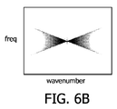
図6A乃至図6Cは、本発明を例示する。センサは、下記の条件を満たして、光軸に沿って移動する。
Vsweep*A/b2>0.25sec−1
図6A乃至図6Cの例では、以下の条件を満たす。
Vsweep=22.4mm/秒(sec)
A=2mm
b=4.002mm
レンズまでの被写体距離=10m
露出時間=0.02秒
Vsweep*A/b2=2.8sec−1
6A-6C illustrate the present invention. The sensor moves along the optical axis satisfying the following conditions.
V sweep * A / b 2 > 0.25 sec −1
In the example of FIGS. 6A to 6C, the following condition is satisfied.
V sweep = 22.4 mm / sec (sec)
A = 2mm
b = 4.002 mm
Subject distance to lens = 10m
Exposure time = 0.02 sec V sweep * A / b 2 = 2.8 sec −1
空間的及び時間的には(図6A)、グラフは、ディアボロの形状を持つ。重要な観点は、様々な速度0km/時、50km/時及び100km/時のPSF関数がほとんど同一である(図6C)ということである。 In space and time (FIG. 6A), the graph has a diabolo shape. An important aspect is that the PSF functions at various speeds of 0 km / h, 50 km / h and 100 km / h are almost identical (FIG. 6C).
PSF関数がほとんど同一なので、単一のIPSF関数を使用して、記録された画像のデコンボリューションが可能であり、示された速度で全ての被写体に対してシャープな画像を取得可能にし、すなわち動き不変の画像又はほとんど動き不変の画像が、100km/時までの任意の速度に対して可能である。レヴィン等の解決策との非常に重要な違いは、10m距離での100km/時までの光軸に垂直な任意の方向の任意の速度に対して、動き不変の画像が可能であることである。このように、レヴィン等が教示する固有の特定の速度方向に対する制限が、取り除かれた。また、PSF関数は、レヴィン等(及びナガハラ)に対するようなくぼみを示さず、よって、原則として、詳細が再構成できる。よって、条件が合えば、光軸に沿ってセンサを動かすことにより、方向に対する制限なしで、かなりの細部を保持した動き不変の画像が可能であることが立証される。ナガハラとの非常に重要な違いは、3つのPSF関数がほとんど同じであり、よって、示される速度に対して動き不変の画像は可能であるのに対し、ナガハラのは可能ではないことである。 Since the PSF functions are almost identical, a single IPSF function can be used to deconvolve the recorded image, making it possible to obtain sharp images for all subjects at the indicated speed, ie motion An invariant image or an almost motion invariant image is possible for any speed up to 100 km / h. A very important difference from the solution of Levin et al. Is that motion invariant images are possible for any speed in any direction perpendicular to the optical axis up to 100 km / hr at 10 m distance. . In this way, the restriction on the specific specific speed direction taught by Levin et al. Has been removed. Also, the PSF function does not show a dimple like that for Levin et al. (And Nagahara), so in principle the details can be reconstructed. Thus, if conditions are met, it can be demonstrated that moving the sensor along the optical axis allows motion-invariant images with significant detail without restriction on direction. A very important difference from Nagahara is that the three PSF functions are almost the same, so a motion invariant image is possible for the indicated speed, whereas Nagahara is not.
本例では、被写体が露出期間の中央で焦点が合っていると仮定されていることに留意されたい。図6Aでは、これは、ディアボロの上部が下部と同じ大きさであるという事実により例示される。これがそうでない場合であっても、動き不変の画像が非常にかなり可能であることが分かった。被写体が露出期間の中央で焦点が合っていず、幾らか前後で焦点が合う場合、大部分の情報が捕捉され、大部分の情報がディアボロの交点周辺に存在するので、非常に良好な動き不変の画像が可能である。以下に、幾らか微細な調整が洞察を持って可能であることが説明される。 Note that in this example, it is assumed that the subject is in focus in the middle of the exposure period. In FIG. 6A, this is illustrated by the fact that the upper part of Diaboro is the same size as the lower part. Even if this is not the case, it has been found that motion-invariant images are quite possible. If the subject is out of focus in the middle of the exposure period and is in focus somewhere in front, most of the information is captured, and most of the information is around the Diabolo intersection, so it has very good motion invariance. Images are possible. In the following, it will be explained that some fine adjustments are possible with insight.
本発明のフレームワークの範囲内で、実施例において、センサは、可能な焦点範囲を越えて掃引される。これは、レンズから幾らか離れた距離の任意の被写体に対する大部分の情報が捕獲されることを保証する。斯様な実施例では、より信頼性が高い動き不変の画像が可能である。 Within the framework of the present invention, in embodiments, the sensor is swept beyond the possible focus range. This ensures that most of the information for any subject at some distance from the lens is captured. In such an embodiment, a motion-invariant image with higher reliability is possible.
本発明のフレームワークの範囲内で、「動き不変の画像」は、任意の詳細なレベルで任意の速度に対して画像の違いがないことを意味するような、非常に厳しい解釈がなされないことに留意されたい。本発明の目的は、実際的な制限内で、動きの変動、すなわち動きぼけを低減することであるり、完全な解決策は、理想であって現実的ではない。 Within the framework of the present invention, “motion-invariant images” are not very strict interpretations, meaning that there is no image difference for any speed at any level of detail. Please note that. The object of the present invention is to reduce motion fluctuations, i.e. motion blur, within practical limits, or a complete solution is ideal and impractical.
発明者は、センサで捕獲された被写体のPSF関数が静的被写体のものと基本的に同じであり、よって動き不変の画像が可能である最大被写体速度が、以下のパラメータに依存すると認識した。
A:被写体のパラメータ、すなわち、被写体の速度対レンズに対する被写体の距離。レンズからより離れている被写体は、レンズにより近い被写体と、同じ速度でより容易に捕獲できる。このパラメータは、基本的に、被写体がセンサ画像を通ってどれくらい速く進むかの尺度を提供する。
B:カメラ又はカメラシステムのパラメータ:
Bl:センサの掃引レート。掃引レートが大きいほど、動き不変の画像が可能である最大被写体速度が高い。
B2:絞り値。絞り値が大きいほど、動き不変の画像が可能である最大被写体速度が高い。
B3:レンズ―センサ距離。
関連したカメラパラメータは、B1*B2/(B3)2、すなわち、Vsweep*A/b2である。
The inventor has recognized that the PSF function of a subject captured by a sensor is basically the same as that of a static subject, and thus the maximum subject speed at which a motion-invariant image is possible depends on the following parameters:
A: Subject parameter, ie subject speed versus subject distance relative to lens. Subjects that are further away from the lens can be captured more easily at the same speed as subjects that are closer to the lens. This parameter basically provides a measure of how fast the subject travels through the sensor image.
B: Camera or camera system parameters:
Bl: sweep rate of the sensor. The higher the sweep rate, the higher the maximum subject speed at which a motion-invariant image is possible.
B2: Aperture value. The larger the aperture value, the higher the maximum subject speed at which a motion-invariant image is possible.
B3: Lens-sensor distance.
The relevant camera parameter is B1 * B2 / (B3) 2 , ie V sweep * A / b 2 .
発明者は、ナガハラによる例で与えられる設定を含む様々な設定をシミュレーションし、不変の画像が可能である被写体に対する最大被写体速度を確立した。 The inventor has simulated various settings, including the settings given in the example by Nagahara, and has established a maximum subject speed for a subject capable of an invariant image.
下記の表1は、結果を示す。第1の列は、ソースについての短いコメントを記述する。ここで、最初2行は、ナガハラの例である(最後の5行は本発明の例を提供する)。他の列は、様々なパラメータを提供する。
表1

Table 1
ナガハラの例は、顕著な動き不変の画像を全く提供しないことは、明らかである。本発明の洞察の助けを借りて、ナガハラの装置で、2メートル離れた距離で被写体に対して最高約0.15km/時の速度に対する動き不変の画像が可能であることが計算できるが、これは実用的でなく、実際に注目に値しない。本発明の例1乃至5に対する不変の速度範囲は、歩いている人又はジョギングしている人の速度から車の速度にわたる実用的な速度範囲である。 It is clear that the Nagahara example does not provide any noticeable motion-invariant images. With the help of the insights of the present invention, it can be calculated that Nagahara's device is capable of motion-invariant images for speeds of up to about 0.15 km / hour for a subject at a distance of 2 meters. Is impractical and not really noteworthy. The constant speed range for Examples 1-5 of the present invention is a practical speed range that ranges from the speed of a walking or jogging person to the speed of a car.
上記表において、ナガハラの例は、f/1.4、しばしば可能な最大絞り値を使用するのに対し、本発明の例1乃至5では、より適度なf/2が使われることに更に留意されたい。同じf/#が使われる場合、不変の速度範囲及びVsweep*A/b2に関する違いは、因子1.4より大きくさえなる。本発明との適当な比較をするために、ナガハラの例に対するf/2の絞り値では、ナガハラの不変の速度範囲は、表に示されるより小さな因子1.4でさえある、すなわち約0.1km/時でさえある。 In the above table, the Nagahara example uses f / 1.4, often the maximum possible aperture value, while the examples 1-5 of the present invention use a more moderate f / 2. I want to be. If the same f / # is used, the difference with respect to the invariant speed range and V sweep * A / b 2 will even be greater than factor 1.4. In order to make a suitable comparison with the present invention, at an aperture value of f / 2 for the Nagahara example, the Nagahara invariant velocity range is even a smaller factor 1.4 than shown in the table, ie about 0. Even 1 km / hour.
例えば監視カメラで撮る場合、不変の速度範囲のための合理的な下位の実際的限界は、監視カメラでは合理的距離の5mの距離で5km/時の速度で歩いている人の速度である。これは、0.25sec−1であるVsweep*A/b2に対する下の限界を提供する。 For example, when shooting with a surveillance camera, a reasonable lower practical limit for a constant speed range is the speed of a person walking at a speed of 5 km / hr at a reasonable distance of 5 m with a surveillance camera. This provides a lower limit for V sweep * A / b 2 which is 0.25 sec −1 .
好ましくは、パラメータVsweep*A/b2は、0.5sec−1を超える、最も好ましくは1sec−1を超える。 Preferably, the parameters V sweep * A / b 2 is greater than 0.5 sec -1, and most preferably greater than 1 sec -1.
好ましくは、パラメータVsweep*A/b2は、15sec−1未満、最も好ましくは5sec−1より小さい。あまりに大きいパラメータは、かなり高い掃引速度又は非常に小さなセンサ距離を必要とする。 Preferably, the parameter V sweep * A / b 2 is less than 15 sec −1 , most preferably less than 5 sec −1 . Too large parameters require fairly high sweep rates or very small sensor distances.
好ましくは、露出時間は、0.005と0.05秒との間、好ましくは0.01と0.05秒との間である。特に、低い光環境で、露出時間のこの範囲は、良好な動き不変の画像の撮像を可能にする。この範囲は、また、ビデオ画像の撮像を可能にする。 Preferably, the exposure time is between 0.005 and 0.05 seconds, preferably between 0.01 and 0.05 seconds. Especially in low light environments, this range of exposure time allows for good motion invariant imaging. This range also allows video images to be captured.
あまりに長い露出時間は、センサの非常に大きな動きを必要とし、おそらくセンサの合理的動きの範囲から出るだろう。 Too long exposure times will require very large movements of the sensor and will probably be out of the reasonable movement range of the sensor.
かなり長い露出時間を依然供給するが、好適な露出時間範囲内で、センサの動きは合理的境界内にある。また、0.01と0.05秒との間の露出時間のこの範囲内で、ビデオシーケンスが作られ得る。 While still providing a fairly long exposure time, within the preferred exposure time range, the sensor motion is within reasonable bounds. Also, a video sequence can be created within this range of exposure times between 0.01 and 0.05 seconds.
好ましくは、センサの動きは、線形である。図6Aでは、これは、ディアボロが2本の直線ライン内にあるという事実により示される。レヴィンにより提案された放物線状の軌跡と同様に、これは、動きの範囲にわたって、サンプリングに、等しい重みを供給する。時間的積分により、発明者は、この空間時間的サンプリングパターンの点広がり関数(PSF)が1/log(x)に比例すると確認した。これは逆関数にするのが容易な関数である。図3B、図4B、図5B乃至図6Bの比較は、ファン(扇)サンプリング(図6B)が、放物線状の軌跡(図4B)より高周波を良く保存し、時空の周波数領域でのsinc変調よりは、少ない欠点であることを示す。結果として、獲得した画像は、逆フィルタリングに対してより良く適している。最後に、ファン状のサンプリングのフェーズ特性は、放物線状の横方向のサンプリングで達成されるものより優れている。 Preferably, the movement of the sensor is linear. In FIG. 6A, this is indicated by the fact that Diabolo is in two straight lines. Similar to the parabolic trajectory proposed by Levin, this provides equal weight to the sampling over the range of motion. Through temporal integration, the inventors have determined that the point spread function (PSF) of this spatiotemporal sampling pattern is proportional to 1 / log (x). This is a function that is easy to reverse. 3B, FIG. 4B, and FIG. 5B to FIG. 6B show that fan sampling (FIG. 6B) preserves high frequency better than a parabolic locus (FIG. 4B), and sinc modulation in the space-time frequency domain. Indicates a minor drawback. As a result, the acquired image is better suited for inverse filtering. Finally, the phase characteristics of fan-like sampling are superior to those achieved with parabolic lateral sampling.
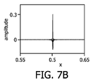
図7A乃至図7Cは、図6CのPSF関数の逆フィルタリングを例示する。図6Cは、図7Aで繰り返される。 7A-7C illustrate inverse filtering of the PSF function of FIG. 6C. FIG. 6C is repeated in FIG. 7A.
図7B及び図7Cの他のフレームは、(中間の)逆フィルタ並びに逆及び順PSFのコンボリューションに対応する。 The other frames in FIGS. 7B and 7C correspond to (intermediate) inverse filters and inverse and forward PSF convolutions.
図7A及び図7Bは、空間PSF及び対応する逆フィルタを示す。逆フィルタは、短い有限空間サインを持つ点に留意されたい。これは、実行することが計算的に効率的であることを意味する。確認のために、図7Cは、所望のユニットパルスである順方向及び逆方向のぼけカーネルのコンボリューションを示す。 7A and 7B show the spatial PSF and the corresponding inverse filter. Note that the inverse filter has a short finite spatial signature. This means that it is computationally efficient to perform. For confirmation, FIG. 7C shows the convolution of the forward and reverse blur kernels, which are the desired unit pulses.
逆フィルタリングの後、全ての被写体は、センサがそれぞれの焦点距離(ディアボロの交差点)で交差したときに被写体があった位置に移動され、よって、深度依存的なフェーズがある(フェーズシフトは、露出の中間での交差に対してゼロである)。しかしながら、レヴィン等のような放物線状の横方向サンプリングは、動き依存的なフェーズシフトが欠点であり、逆フィルタリングの後、全ての被写体がそれらの位置でシャープに見えるが、わずかに異なる時間でそれらの位置を被写体は移動していた。これは、結果的に小さな不整合、特に動き境界及び遮蔽領域で小さな不整合となる。レヴィン等と比較して、このことは、本発明のための重要な利点を提供する。 After inverse filtering, all subjects are moved to the location where the subject was when the sensors crossed at their respective focal lengths (Diaboro intersection), so there is a depth-dependent phase (phase shift is exposure Is zero for intersections in between). However, parabolic lateral sampling, such as Levin, is disadvantageous for motion-dependent phase shifts, and after inverse filtering, all subjects appear sharp at their positions, but at slightly different times The subject was moving. This results in small inconsistencies, especially at motion boundaries and occlusion areas. Compared to Levin et al., This provides an important advantage for the present invention.
好ましくは、効果的な空間ぼけカーネルは、時間とともに線形に変化する。これは、光軸に沿ってセンサと主レンズとの間の距離を線形に変調することにより達成できる。これは、焦点ぼけの程度がセンサ変位と比例しているという事実による。画像を撮る前又はシャッタが閉じるときであるが、斯様な動きは、ほとんどのオートフォーカスのカメラで既に行われている。結果として、動き及びシャッタが制御され、十分に正確に同期できるとすると、画像を撮る間、動きを実施することにより、幾つかのカメラで、オートフォーカスの機械が、所望のサンプリングを達成するために使用できることは、容易に想像できる。 Preferably, the effective spatial blur kernel varies linearly with time. This can be achieved by linearly modulating the distance between the sensor and the main lens along the optical axis. This is due to the fact that the degree of defocus is proportional to the sensor displacement. Such movement is already done with most autofocus cameras, either before taking an image or when the shutter closes. As a result, assuming that the motion and shutter are controlled and can be synchronized sufficiently accurately, with some cameras, the autofocus machine achieves the desired sampling by performing the motion while taking an image. You can easily imagine what you can use.
Vsweep*A/b2が露出の間に変化する場合、関連パラメータは、露出時間にわたるVsweep*A/b2の時間平均であることに留意されたい。図1に関係して説明されたように、必要な空間的時間的サンプリングの代替の実施例は、露出時間の間、センサ―レンズ変位を固定して、主レンズの焦点距離を掃引することである(図1の下部)。明らかに、これは、液体焦点レンズ又は複屈折LC物質のような切換可能な光学系を必要とする。切換可能なLCベースのレンズは、3Dスクリーンで適用され、これらレンズは、2D(レンズ効果がない)と3Dモードとの間で変化するために用いられる。屈折率は、一方向だけ変化できる(円柱状レンズだけ)。可変の焦点距離は、また、液体圧によって変形できる流体充填膜で達成できる。また、好ましくは、画像平面は、時間とともに線形に掃引される。
b=b0+c0t
画像平面距離は、以下のレンズ式を介して被写体距離及びレンズの焦点距離に関係する。
1/f=1/v+1/b
Note that if V sweep * A / b 2 changes during exposure, the relevant parameter is the time average of V sweep * A / b 2 over the exposure time. As described in connection with FIG. 1, an alternative embodiment of the required spatial and temporal sampling is to fix the sensor-lens displacement and sweep the focal length of the main lens during the exposure time. Yes (bottom of FIG. 1). Obviously, this requires a switchable optical system such as a liquid focus lens or a birefringent LC material. Switchable LC-based lenses are applied in 3D screens, which are used to change between 2D (no lens effect) and 3D mode. The refractive index can only change in one direction (only cylindrical lenses). A variable focal length can also be achieved with a fluid-filled membrane that can be deformed by liquid pressure. Also preferably, the image plane is swept linearly with time.
b = b 0 + c 0 t
The image plane distance is related to the subject distance and the focal length of the lens via the following lens formula.
1 / f = 1 /
よって、焦点距離は、下記の式に従って、好ましくは時間とともに変化されることになる。
f(t)=1/(1/v+1/(b0+c0t))
ここで、f(t)は時間の関数としてレンズ焦点距離を示し、c0は定数である。
Thus, the focal length preferably varies with time according to the following equation:
f (t) = 1 / (1 /
Here, f (t) represents a focal length of the lens as a function of time, c 0 is a constant.
よって、2つの組合せも、例えば、時間的空間的サンプリングの量を増大するが(すなわち図6Aのディアボロの程度)センサの物理的動き又はその掃引速度を制限するか、又は掃引速度を増大するために可能である。 Thus, the two combinations also, for example, increase the amount of temporal and spatial sampling (ie, the degree of diaboro in FIG. 6A) to limit the physical movement of the sensor or its sweep speed, or to increase the sweep speed. Is possible.
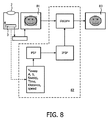
図8は、記録された画像をデコンボリュートするための方法と、画像データを記録し、記録された画像データのデコンボリュートをするためのシステムとを例示する。画像は、レンズ2及び可動センサ3を有するカメラにより記録される。センサのデータは、リーダーにより読み込まれる。対応する画像81は、ぼやけているように模式的に示される。記録された画像は、デコンボリュータ82でデコンボリュートされる。このようにシステムは、画像データをデコンボリュートするデコンボリュータを有する。当該方法は、記録された画像データをデコンボリュートする。デコンボリュータは、記録された画像上でデコンボリューション動作を実施する。理解の容易さのために、アルゴリズム及び方法が、複数のステップで示される。第1のステップは、点広がり関数を計算することである。単純な実施例では、点広がり関数は、パラメータVsweep*A/bに依存している。単純な実施例では、PSF関数は、掃引範囲の中央の静的被写体に対して計算される。上述されたように、広範囲の速度に対して、PSF関数は、本発明の実施例に対して速度とほとんど無関係なので、掃引範囲の中央で静的被写体に対するIPSFは、全ての速度に対する最適PSFのための良好な一次オーダーの近似となるだろう。より高度な実施例では、被写体の距離は、PSFを微調整し、これによりIPSFを微調整するために用いられる。被写体の距離は、例えばカメラにより記録できる。ほとんどのカメラは、被写体距離の測定を可能にするある種類の自動焦点を持つ。上述されたように、被写体が掃引動作の中央で焦点が合っていない場合であっても、不変の画像が非常に良く可能であることが分かった。被写体が露出期間の中央で焦点が合っていないが、その幾らか前後で合っている場合、ほとんどの情報はディアボロの交差点周辺に存在するので、ほとんどの情報が捕捉され、非常に良好な動き不変の画像が可能である。しかしながら、掃引範囲の中央で静的被写体に対するPSF関数を使用することが良好な結果を与えるにもかかわらず、幾らか改良された結果が、PSFを被写体距離及びおそらく他のパラメータに依存させることによりPSFを微調整することで得られる。これは、幾らか非対称で切り取られたPSFを提供するだろう。最終結果は、レンズから特定の距離以外の距離では幾らかシャープでない画像の犠牲で、レンズから特定の距離の移動物体に対して幾らかよりシャープな画像となるだろう。被写体距離は、本発明の実施例では、掃引レートを決定するためにも使用できることに留意されたい。上述されたように、決定因子は、レンズまでの距離で割られる被写体の速度である。このように所与の速度の2m距離の被写体に対して、同一速度の10m距離の被写体と比較すると、より速い掃引速度を使用する、すなわちVsweepを増大することが好適にできる。本発明によるカメラを動作させる方法の実施例では、レンズまでの被写体の距離、被写体の速度、被写体の速度の方向から成るパラメータのグループの少なくとも一つ以上が測定され、掃引速度が、測定されたパラメータに依存して設定される。これは、次に、PSFのパラメータに対する影響を持つだろう。
FIG. 8 illustrates a method for deconvolving recorded images and a system for recording image data and deconvolving recorded image data. The image is recorded by a camera having a
被写体の速度は、デコンボリュータ82の入力でもある。また、本発明は全ての速度に対して単一のPSF関数を使用可能にするが、PSFが特定の速度に対して微調整できる幾らか2次のオーダーの効果が依然可能である。アプリケーションの可能なフィールドは、被写体の速度及び方向の良好な見積もりを既に提供する速度カメラである。
The speed of the subject is also an input to the
計算は、小さな2次のオーダーの動き方向依存性がPSFに存在することを示した。実施例では、方向の範囲に対する最適PSFが計算され、使用されるPSFは、方向の入力に依存した、この範囲内の選択である。選択は、例えば最大、最低限、中央値、重み付け平均等である。 The calculation showed that a small second order motion direction dependence exists in the PSF. In an embodiment, an optimal PSF for a range of directions is calculated, and the PSF used is a selection within this range depending on the direction input. The selection is, for example, maximum, minimum, median, weighted average, or the like.
掃引時間も入力である。 The sweep time is also an input.
要するに、デコンボリュータは、使用されるべきPSFを微調整する入力を持つ。様々なパラメータが図8に例示されているが、最も重要なパラメータは、掃引レート、被写体距離及び速度並びに速度の方向である。 In short, the deconvolver has an input that fine tunes the PSF to be used. Various parameters are illustrated in FIG. 8, but the most important parameters are sweep rate, subject distance and velocity, and velocity direction.
デコンボリュートされたシャープな画像83は、図8の右側に示される。
A deconvoluted
当該方法を容易に理解するために、システム及びアルゴリズムが、PSFで始まり、その後、PSFから逆PSFを取り出す様々なステップで示される。もちろん、IPSFはデコンボリューションの重要な関数であり、IPSFはPSFの逆関数であり、逆もまた然りであるので、直接IPSFで始めることもでき、デコンボリューションで使用されるべきIPSFを決定するため、様々な入力は、PSF使用のために適当な様式で翻訳されると、正に同様な入力となる。 To easily understand the method, the system and algorithm are shown in various steps starting with PSF and then extracting the inverse PSF from the PSF. Of course, since IPSF is an important function of deconvolution, and IPSF is the inverse function of PSF, and vice versa, it can also start directly with IPSF and determine the IPSF to be used in deconvolution. Thus, the various inputs will be exactly similar when translated in an appropriate manner for PSF use.
好ましくは、記録の間、センサの動きは、一方向だけであり、例えばレンズに向かう方向だけである。一次のオーダー近似値では、デコンボリュートされた画像が、センサの掃引の方向から同じく独立している、すなわちセンサがレンズへ向かって動いているか離れているかに無関係であり、2次のオーダー近似値では、これは、センサの掃引の中央で焦点が合っている被写体に対してだけ、真であると厳格に言える。レンズにより近く又は離れた被写体に対して、結果の小さな違いがあり、特にデコンボリュートされた画像の被写体の位置に関して違いがある。単一の画像では、この違いは感知できないか、ほとんど感知できないが、ビデオシーケンスでは、被写体の位置での激しい揺れが発生する。この効果の発生を回避するために、露出の間のセンサの動きは、好ましくは片寄っている、すなわち一方向だけである。もちろん、次のデータが記録できる前に、センサは初期位置へ戻っていなければならない。本実施例では、センサが初期位置へ戻ることを可能にするために、露出時間に対する付加的な制限がある。 Preferably, during recording, the movement of the sensor is only in one direction, for example in the direction towards the lens. In the first order approximation, the deconvoluted image is also independent of the direction of the sensor sweep, i.e. independent of whether the sensor is moving towards or away from the lens, and the second order approximation. So this is strictly true only for the subject in focus at the center of the sensor sweep. There are minor differences in results for subjects closer or further away from the lens, especially with respect to the location of the subject in the deconvoluted image. In a single image, this difference cannot be perceived or is hardly perceived, but in a video sequence, severe shaking occurs at the location of the subject. In order to avoid the occurrence of this effect, the movement of the sensor during exposure is preferably offset, i.e. only in one direction. Of course, the sensor must return to the initial position before the next data can be recorded. In this embodiment, there is an additional limit on the exposure time to allow the sensor to return to the initial position.
図9は、センサの動きを例示する。ライン91はセンサが進んだ距離を表し、ライン92はセンサの速度を表わす。第1の時間の間、センサは、速度が0から(しばらくの間維持される)一定の速度まで増大する事実によりライン92で示される速度まで上昇する。その後、センサは、停止されて、すぐに最初の位置に戻される。センサの戻りは、時間データの一部だけが記録され、この例では例えば時間のほぼ50―70%だけが記録できることを意味する。例えば単一のショットがなされる場合に可能である、センサが前後に移動するとき、センサはその最初の位置に戻される必要はない。上述されたように、動きは、センサ若しくはレンズを物理的に動かすか、又はレンズの特性を変えることにより、2つの異なる態様又はそれらの組み合わせで生じる。
FIG. 9 illustrates the movement of the sensor.
短い露出時間又はセンサの速い動きのために、レンズの特性の変化を動きの少なくとも一部に対して使用することは有利である。 Due to the short exposure time or fast movement of the sensor, it is advantageous to use a change in the lens properties for at least part of the movement.
要するに、本発明による動き不変のカメラは、特に低い照明状況の下で、シャープな高品質のビデオ又は画像を提供する。消費者向けカメラ及びビデオカメラを含むほとんどのカメラ及び光画像システムのために有益であるが、これは幾つかの専門の監視及びアプリケーションの監視に特に価値がある。例えば、セキュリティシステムの監視カメラは、暗い周囲で動作することをしばしば必要とする。現在の監視カメラは、所望のSNRレベルを得るためにセンサ冷却のような高価なフィーチャを持つ。本発明は、高いダイナミックレンジカメラのコスト価値の高い代替物を供給するか、又は現在のセンサのダイナミックレンジをより一層増大させるために用いられる。本発明は、光をサンプリングする新規な態様を説明し、従って、既存のフォトセンサ技術を使用して実行できる点に留意されたい。 In short, a motion-invariant camera according to the present invention provides a sharp high quality video or image, especially under low lighting conditions. Although beneficial for most cameras and optical imaging systems, including consumer cameras and video cameras, this is particularly valuable for some specialized monitoring and application monitoring. For example, security system surveillance cameras often need to operate in dark surroundings. Current surveillance cameras have expensive features such as sensor cooling to obtain the desired SNR level. The present invention can be used to provide a cost-effective alternative to high dynamic range cameras or to further increase the dynamic range of current sensors. It should be noted that the present invention describes a novel way of sampling light and thus can be implemented using existing photosensor technology.
本発明は、露出の間、レンズとセンサとの間の距離と、焦点距離との比が変えられるカメラ、及びカメラを有するシステムとして説明できる。動き不変の画像が、複合画像をデコンボリュートすることにより実用的な速度範囲、すなわちレンズの2m距離で少なくとも5km/時までの速度に対して達成可能であるように、変化のレートが設定される。好ましくは、達成可能な速度範囲は、少なくとも2倍高い。センサの線形動きが好ましい。 The present invention can be described as a camera and a system having a camera in which the ratio between the distance between the lens and the sensor and the focal length is changed during exposure. The rate of change is set so that a motion-invariant image is achievable for a practical speed range by deconvoluting the composite image, ie at speeds up to at least 5 km / hr at 2 m distance of the lens . Preferably, the achievable speed range is at least twice as high. A linear movement of the sensor is preferred.
上述した方法及び装置は、シーン内で、結果的にセンサ上で起こる被写体速度について何も知る必要なく手探りで動作するが、増大された速度についての情報を持つ場合、再構成の正確さ(すなわち、より鋭く/より良い最終的な画像)が達成できる点に留意されたい。これは、静的になされるか(例えば、分析されるべき被写体が通り過ぎるベルトコンベヤーの速度を知っている、マシンビジョンアプリケーションで、例えばどれくらいの通常速度が発生しているかを知っている)、又はシステムが(例えば反復的に)シーンの被写体の速度を測定し、下記の代替の実施例のパラメータを最適に調整するように動的になされ得る。 The method and apparatus described above operate fuzzlessly in the scene without the need to know anything about the subject speed that occurs on the sensor, but if there is information about the increased speed, the reconstruction accuracy (ie, Note that a sharper / better final image) can be achieved. This can be done statically (for example, knowing how fast the normal speed is occurring in a machine vision application, knowing the speed of the belt conveyor through which the subject to be analyzed passes), or The system can be made dynamically to measure the speed of the subject in the scene (eg, iteratively) and optimally adjust the parameters of the alternative embodiments described below.
第1の改良は、例えばレンズの前又はレンズとセンサとの間等にある液晶素子でなされ得る起こっている被写体速度に適合した(コード化された)絞り値を選択することから成る。例えば、通常の被写体速度(例えば、シーンの主要な被写体の平均速度)v_averageと、他の被写体速度(例えば電車に揺れている人)からのそのずれCmaxとを持つ場合、下記の式に従ってオリジナルの絞り値の円形サブエリアを選択できる。
α=xf2/(VL(x−f)2)
xは被写体(撮像されるポイント)からレンズまでの距離であり、fはレンズ焦点距離、VLはセンサの光軸に沿った変位の速度である。dmaxは、画像平面上の被写体画像の位置に関する不確定パラメータである(すなわち、センサ中心から距離dでセンサ上の位置にある被写体ポイントからレンズ中心を通る中央光線は、距離d<dmaxを持たなければならない)。これは、α倍のv_averageで変位される、1.25*alpha*Cmax+dmaxの半径を持つ円に対応する。
The first improvement consists of selecting an aperture value (coded) that is adapted to the object speed that is taking place that can be made with a liquid crystal element, for example in front of the lens or between the lens and the sensor. For example, if there is a normal subject speed (for example, the average speed of the main subject in the scene) v_average and its deviation Cmax from other subject speeds (for example, people swinging on a train), A circular sub-area with an aperture value can be selected.
α = xf 2 / (V L (x−f) 2 )
x is the distance from the subject (the imaged point) to the lens, f is the lens focal length, and VL is the displacement speed along the optical axis of the sensor. dmax is an uncertain parameter relating to the position of the subject image on the image plane (ie, the central ray passing through the lens center from the subject point at a position d on the sensor at a distance d from the sensor center must have a distance d <dmax. Must). This corresponds to a circle with a radius of 1.25 * alpha * Cmax + dmax, displaced by α times v_average.
もちろん、より複雑な絞り値が適切に決定できる、例えば被写体を回転させるためのリング形状で決定できる。 Of course, a more complex aperture value can be appropriately determined, for example, a ring shape for rotating the subject.
通常の被写体速度知識が付与された画像(例えば、速度v_objで動く被写体と静的背景)を改善する他の実施例は、光軸に沿ってセンサを動かすだけでなく、直角に動かすことである(斜めの複合動きを作る)。 Another example of improving an image given normal subject speed knowledge (eg, a subject moving at a speed v_obj and a static background) is to move the sensor not only along the optical axis but also at a right angle. (Make diagonal compound movement).
被写体の動き追跡は、パニング動きでカメラ全体を動かすか、又は代わりに光軸と直角をなすセンサの並進によりなされ得る。 Object motion tracking can be done by moving the entire camera with panning motion, or alternatively by translation of a sensor perpendicular to the optical axis.
この実施例によると、動き追跡を焦点掃引概念と結合でき、光軸と角度をなす画像平面を移動させるシステムを作る。実施例の方法又は装置は、センサ動きを2つの直角ベクトル、光軸に沿ったVsweepとそれに対して垂直なVTRとに分解する。 According to this embodiment, motion tracking can be combined with the focus sweep concept, creating a system that moves an image plane that is angled with the optical axis. An example method or apparatus decomposes sensor motion into two orthogonal vectors, V sweep along the optical axis and V TR perpendicular thereto.
VTRに沿ったセンサの並進は、平均被写体速度
動きゼロを中心に置く代わりに、不変の速度の範囲は、追跡速度
すなわち、掃引速度は、不変の速度の事前に決められた範囲をカバーするように選ばれる。
被写体速度がシャープな画像を生成するために必ずしも整合される必要がないことに留意されたい。被写体の速度が不変の範囲内にある(すなわち、例では移動物体速度v_obj及びゼロの静的速度両方をカバーする)限り、シャープな再構成は可能である。 Note that subject speed does not necessarily have to be matched to produce a sharp image. As long as the speed of the subject is in a constant range (ie, in the example covers both moving object speed v_obj and zero static speed), sharp reconstruction is possible.
すなわち、より正確な追跡を少なめの掃引と交換できるし、又は逆もでき、(少なくとも幾つかの被写体の)追跡をあまり正確にしないが、より広いDCI円錐、すなわちより大きいセンサ掃引をすることもできる。好ましくは、掃引速度及び並進は、静止被写体及び移動被写体両方が正しく再構成できるように一緒に最適化される。 That is, more accurate tracking can be exchanged for less sweep, or vice versa, and tracking (at least some subjects) is less accurate, but can also have a wider DCI cone, ie a larger sensor sweep. it can. Preferably, sweep speed and translation are optimized together so that both stationary and moving subjects can be correctly reconstructed.
他の実施例は、光軸に垂直にセンサをオフセットすることにより、画像品質を増大させる。センサ上のシーン被写体の動きが画像システムを通じた幾何学的な投影及びセンサ自体の動き両方の関数であるので、以下の式となる。
ここで、vは画像被写体であり、yは理論的にシャープである画像平面(通常はセンサ掃引の中央の点である)とレンズとの間の距離であり、dは画像ポイントのセンサ中心からの距離であり、VLはセンサ掃引速度である。 Where v is the image subject, y is the distance between the theoretically sharp image plane (usually the center point of the sensor sweep) and the lens, and d is from the sensor center of the image point. VL is the sensor sweep speed.
動きぼけを低減するため、このセンサ速度を小さくしたい本実施例によると、これは例えばセンサのオフセットを下記の式で選択することによりなされ得る。
下記の速度でセンサを変位させる場合、
上記3つの実施例では、所望する再構成精度及び例えば逆フィルタの複雑さに依存して、これらを選択するだけでなく、様々な程度で、上記3つの原理を組み合わせて、例えば、より最適なセンサ変位(平均的に)を選択することにより、光軸及び/又は直交動きに沿った掃引を低減できるので、幾つかのパラメータ最適値(例えば、幾つかの絞り値形状(例えばサイズ)、幾つかの直交動き、幾つかのセンサ変位)を選択できることに留意されたい。 The above three embodiments not only select these depending on the desired reconstruction accuracy and, for example, the complexity of the inverse filter, but also combine the above three principles to varying degrees, for example, more optimal By selecting sensor displacement (on average), sweep along the optical axis and / or orthogonal motion can be reduced, so that some parameter optimums (eg some aperture shape (eg size), some Note that some orthogonal motion, several sensor displacements) can be selected.
Claims (17)
Vsweep*A/b2>0.25sec−1
を満たすように前記比を変化させることを特徴とし、ここで、Vsweepは光軸に沿った前記センサの動き及び/若しくはレンズの動き並びに/又は秒あたりの焦点距離の変化であり、Aは前記レンズの絞り値であり、bはレンズとセンサとの間の距離である、カメラ。 A camera for recording an image having a lens and an image sensor, wherein a ratio between a distance between the lens and the image sensor along the optical axis and a focal length changes during an exposure time of imaging. In the camera, the camera has V sweep * A / b 2 > 0.25 sec −1
Characterized by varying the ratio to satisfy, where, V sweep is the change of the focal distance per movement and / or second movement and / or lens of the sensor along the optical axis, A is The aperture value of the lens , and b is the distance between the lens and the sensor.
Vsweep*A/b2>0.25sec−1
を満たすことを特徴とし、ここで、Vsweepは光軸に沿った前記センサの動き及び/若しくはレンズの動き並びに/又は秒あたりの焦点距離の変化であり、Aは絞り値であり、bは前記レンズと前記センサとの間の距離である、方法。 A method for recording an image using a camera having a lens and an image sensor, wherein the ratio between the distance between the lens and the image sensor and the focal length is a light during the exposure time of the image. Along the axis, during image recording,
V sweep * A / b 2 > 0.25 sec −1
Where V sweep is the movement of the sensor and / or the movement of the lens along the optical axis and / or the change in focal length per second, A is the aperture value, and b is The method, which is the distance between the lens and the sensor.
Applications Claiming Priority (5)
| Application Number | Priority Date | Filing Date | Title |
|---|---|---|---|
| EP09160007 | 2009-05-12 | ||
| EP09160007.2 | 2009-05-12 | ||
| EP09163440 | 2009-06-23 | ||
| EP09163440.2 | 2009-06-23 | ||
| PCT/IB2010/051847 WO2010131142A1 (en) | 2009-05-12 | 2010-04-28 | Camera, system comprising a camera, method of operating a camera and method for deconvoluting a recorded image |
Publications (3)
| Publication Number | Publication Date |
|---|---|
| JP2012527145A JP2012527145A (en) | 2012-11-01 |
| JP2012527145A5 JP2012527145A5 (en) | 2013-06-13 |
| JP5522757B2 true JP5522757B2 (en) | 2014-06-18 |
Family
ID=42310697
Family Applications (1)
| Application Number | Title | Priority Date | Filing Date |
|---|---|---|---|
| JP2012510394A Active JP5522757B2 (en) | 2009-05-12 | 2010-04-28 | Camera, system having camera, method of operating camera, and method of deconvolving recorded image |
Country Status (7)
| Country | Link |
|---|---|
| US (1) | US8605202B2 (en) |
| EP (1) | EP2430826A1 (en) |
| JP (1) | JP5522757B2 (en) |
| CN (1) | CN102422629B (en) |
| RU (1) | RU2529661C2 (en) |
| TW (1) | TWI521961B (en) |
| WO (1) | WO2010131142A1 (en) |
Families Citing this family (33)
| Publication number | Priority date | Publication date | Assignee | Title |
|---|---|---|---|---|
| WO2011083411A1 (en) | 2010-01-05 | 2011-07-14 | Koninklijke Philips Electronics N.V. | Image projection apparatus and method |
| US8537238B2 (en) * | 2010-04-14 | 2013-09-17 | Sony Corporation | Digital camera and method for capturing and deblurring images |
| JP5591090B2 (en) * | 2010-12-13 | 2014-09-17 | キヤノン株式会社 | Image processing apparatus and method |
| WO2012083968A1 (en) | 2010-12-21 | 2012-06-28 | 3Shape A/S | Motion blur compensation |
| WO2012104759A1 (en) * | 2011-02-04 | 2012-08-09 | Koninklijke Philips Electronics N.V. | Method of recording an image and obtaining 3d information from the image, camera system |
| EP2688284B1 (en) * | 2011-03-14 | 2017-10-25 | Panasonic Corporation | Imaging device, imaging method, integrated circuit, and computer program |
| EP2503364A1 (en) | 2011-03-22 | 2012-09-26 | Koninklijke Philips Electronics N.V. | Camera system comprising a camera, camera, method of operating a camera and method for deconvoluting a recorded image |
| US9189451B1 (en) | 2011-10-06 | 2015-11-17 | RKF Engineering Solutions, LLC | Detecting orbital debris |
| JP2013110700A (en) * | 2011-11-24 | 2013-06-06 | Samsung Electronics Co Ltd | Imaging apparatus, imaging method, and image processing apparatus |
| US9813607B2 (en) * | 2011-12-16 | 2017-11-07 | Nokia Technologies Oy | Method and apparatus for image capture targeting |
| US8693731B2 (en) | 2012-01-17 | 2014-04-08 | Leap Motion, Inc. | Enhanced contrast for object detection and characterization by optical imaging |
| US9501152B2 (en) | 2013-01-15 | 2016-11-22 | Leap Motion, Inc. | Free-space user interface and control using virtual constructs |
| US11493998B2 (en) | 2012-01-17 | 2022-11-08 | Ultrahaptics IP Two Limited | Systems and methods for machine control |
| US10691219B2 (en) | 2012-01-17 | 2020-06-23 | Ultrahaptics IP Two Limited | Systems and methods for machine control |
| US8638989B2 (en) | 2012-01-17 | 2014-01-28 | Leap Motion, Inc. | Systems and methods for capturing motion in three-dimensional space |
| US9679215B2 (en) | 2012-01-17 | 2017-06-13 | Leap Motion, Inc. | Systems and methods for machine control |
| WO2013144427A1 (en) * | 2012-03-26 | 2013-10-03 | Nokia Corporation | Method, apparatus and computer program product for image stabilization |
| CN103379269B (en) * | 2012-04-26 | 2017-11-24 | 富泰华工业(深圳)有限公司 | Camera system, image pickup method and the electronic equipment using the camera system |
| US9191578B2 (en) * | 2012-06-29 | 2015-11-17 | Broadcom Corporation | Enhanced image processing with lens motion |
| US9459697B2 (en) | 2013-01-15 | 2016-10-04 | Leap Motion, Inc. | Dynamic, free-space user interactions for machine control |
| US20140210707A1 (en) * | 2013-01-25 | 2014-07-31 | Leap Motion, Inc. | Image capture system and method |
| US9558555B2 (en) | 2013-02-22 | 2017-01-31 | Leap Motion, Inc. | Adjusting motion capture based on the distance between tracked objects |
| US9733715B2 (en) | 2013-03-15 | 2017-08-15 | Leap Motion, Inc. | Resource-responsive motion capture |
| US9702977B2 (en) | 2013-03-15 | 2017-07-11 | Leap Motion, Inc. | Determining positional information of an object in space |
| US9916009B2 (en) | 2013-04-26 | 2018-03-13 | Leap Motion, Inc. | Non-tactile interface systems and methods |
| US10281987B1 (en) | 2013-08-09 | 2019-05-07 | Leap Motion, Inc. | Systems and methods of free-space gestural interaction |
| US10846942B1 (en) | 2013-08-29 | 2020-11-24 | Ultrahaptics IP Two Limited | Predictive information for free space gesture control and communication |
| US9632572B2 (en) | 2013-10-03 | 2017-04-25 | Leap Motion, Inc. | Enhanced field of view to augment three-dimensional (3D) sensory space for free-space gesture interpretation |
| US9996638B1 (en) | 2013-10-31 | 2018-06-12 | Leap Motion, Inc. | Predictive information for free space gesture control and communication |
| EP3117597A1 (en) * | 2014-03-12 | 2017-01-18 | Sony Corporation | Method, system and computer program product for debluring images |
| DE202014103729U1 (en) | 2014-08-08 | 2014-09-09 | Leap Motion, Inc. | Augmented reality with motion detection |
| EP3370410B1 (en) * | 2015-10-26 | 2020-11-25 | Kyocera Corporation | Imaging device |
| CN112104808B (en) * | 2019-06-18 | 2022-06-21 | 长城汽车股份有限公司 | Image acquisition device and have its vision processing system, unmanned vehicle |
Family Cites Families (8)
| Publication number | Priority date | Publication date | Assignee | Title |
|---|---|---|---|---|
| US5134432A (en) * | 1990-02-14 | 1992-07-28 | Asahi Kogaku Kogyo Kabushiki Kaisha | Camera with mid-exposure zooming function |
| JP4393864B2 (en) | 2001-06-18 | 2010-01-06 | コーニンクレッカ フィリップス エレクトロニクス エヌ ヴィ | Motion blur removal display |
| KR20040103786A (en) * | 2003-06-02 | 2004-12-09 | 펜탁스 가부시키가이샤 | A multiple-focal-length imaging device, and a mobile device having the multiple-focal-length imaging device |
| US7330594B2 (en) * | 2003-07-31 | 2008-02-12 | Kabushiki Kaisha Toshiba | Image enhancement or correction software, method, apparatus and system for substantially minimizing blur in the scanned image |
| JP5013705B2 (en) * | 2005-11-21 | 2012-08-29 | 三星電子株式会社 | Imaging device, screen display method, focus adjustment method, exposure adjustment method, and computer program |
| US7711259B2 (en) * | 2006-07-14 | 2010-05-04 | Aptina Imaging Corporation | Method and apparatus for increasing depth of field for an imager |
| WO2009120718A1 (en) * | 2008-03-24 | 2009-10-01 | The Trustees Of Columbia University In The City Of New York | Methods, systems, and media for controlling depth of field in images |
| US8451338B2 (en) * | 2008-03-28 | 2013-05-28 | Massachusetts Institute Of Technology | Method and apparatus for motion invariant imaging |
-
2010
- 2010-04-28 JP JP2012510394A patent/JP5522757B2/en active Active
- 2010-04-28 EP EP10719389A patent/EP2430826A1/en not_active Ceased
- 2010-04-28 US US13/319,800 patent/US8605202B2/en active Active
- 2010-04-28 RU RU2011150257/28A patent/RU2529661C2/en active
- 2010-04-28 WO PCT/IB2010/051847 patent/WO2010131142A1/en active Application Filing
- 2010-04-28 CN CN201080020801.4A patent/CN102422629B/en active Active
- 2010-05-07 TW TW099114708A patent/TWI521961B/en active
Also Published As
| Publication number | Publication date |
|---|---|
| RU2529661C2 (en) | 2014-09-27 |
| CN102422629B (en) | 2015-04-29 |
| RU2011150257A (en) | 2013-06-20 |
| EP2430826A1 (en) | 2012-03-21 |
| CN102422629A (en) | 2012-04-18 |
| TWI521961B (en) | 2016-02-11 |
| US8605202B2 (en) | 2013-12-10 |
| WO2010131142A1 (en) | 2010-11-18 |
| US20120062787A1 (en) | 2012-03-15 |
| JP2012527145A (en) | 2012-11-01 |
| TW201106682A (en) | 2011-02-16 |
Similar Documents
| Publication | Publication Date | Title |
|---|---|---|
| JP5522757B2 (en) | Camera, system having camera, method of operating camera, and method of deconvolving recorded image | |
| US8432434B2 (en) | Camera and method for focus based depth reconstruction of dynamic scenes | |
| JP5870264B2 (en) | Imaging apparatus, imaging method, program, and integrated circuit | |
| JP5868183B2 (en) | Imaging apparatus and imaging method | |
| CN106412426B (en) | Total focus camera and method | |
| JP5134694B2 (en) | Image processing apparatus and image processing method | |
| KR101494066B1 (en) | Generation of depth data based on spatial light pattern | |
| JP5976772B2 (en) | Camera system having camera, camera, method of operating camera, and method of analyzing recorded image | |
| WO2010016625A1 (en) | Image photographing device, distance computing method for the device, and focused image acquiring method | |
| CN102369722B (en) | Camera head and image capture method and the image processing method for described camera head | |
| US9407827B2 (en) | Method and system for capturing sequences of images with compensation for variations in magnification | |
| JP6202910B2 (en) | Video processing apparatus, control method therefor, and program | |
| GB2545551A (en) | Imaging device and imaging method | |
| JP2018017876A (en) | Imaging apparatus and control method of the same, and image processing apparatus and method | |
| JP2012142729A (en) | Camera | |
| US10151933B2 (en) | Apparatus and optical system including an optical element | |
| JP4460711B2 (en) | Imaging device | |
| JP6625184B2 (en) | Focus detection device, imaging device, focus detection method, and focus detection program | |
| JP7463078B2 (en) | Imaging device | |
| Nagahara et al. | Computational photography using programmable aperture |
Legal Events
| Date | Code | Title | Description |
|---|---|---|---|
| A521 | Request for written amendment filed |
Free format text: JAPANESE INTERMEDIATE CODE: A523 Effective date: 20130424 |
|
| A621 | Written request for application examination |
Free format text: JAPANESE INTERMEDIATE CODE: A621 Effective date: 20130424 |
|
| TRDD | Decision of grant or rejection written | ||
| A01 | Written decision to grant a patent or to grant a registration (utility model) |
Free format text: JAPANESE INTERMEDIATE CODE: A01 Effective date: 20140307 |
|
| RD02 | Notification of acceptance of power of attorney |
Free format text: JAPANESE INTERMEDIATE CODE: A7422 Effective date: 20140403 |
|
| A61 | First payment of annual fees (during grant procedure) |
Free format text: JAPANESE INTERMEDIATE CODE: A61 Effective date: 20140403 |
|
| R150 | Certificate of patent or registration of utility model |
Ref document number: 5522757 Country of ref document: JP Free format text: JAPANESE INTERMEDIATE CODE: R150 |
|
| R250 | Receipt of annual fees |
Free format text: JAPANESE INTERMEDIATE CODE: R250 |
|
| R250 | Receipt of annual fees |
Free format text: JAPANESE INTERMEDIATE CODE: R250 |
|
| R250 | Receipt of annual fees |
Free format text: JAPANESE INTERMEDIATE CODE: R250 |
|
| R250 | Receipt of annual fees |
Free format text: JAPANESE INTERMEDIATE CODE: R250 |
|
| R250 | Receipt of annual fees |
Free format text: JAPANESE INTERMEDIATE CODE: R250 |
|
| R250 | Receipt of annual fees |
Free format text: JAPANESE INTERMEDIATE CODE: R250 |
|
| R250 | Receipt of annual fees |
Free format text: JAPANESE INTERMEDIATE CODE: R250 |