JP5745644B2 - Optoelectronic device, system, and method for obtaining ambient light spectrum and changing emission - Google Patents
Optoelectronic device, system, and method for obtaining ambient light spectrum and changing emission Download PDFInfo
- Publication number
- JP5745644B2 JP5745644B2 JP2013546618A JP2013546618A JP5745644B2 JP 5745644 B2 JP5745644 B2 JP 5745644B2 JP 2013546618 A JP2013546618 A JP 2013546618A JP 2013546618 A JP2013546618 A JP 2013546618A JP 5745644 B2 JP5745644 B2 JP 5745644B2
- Authority
- JP
- Japan
- Prior art keywords
- light
- optoelectronic device
- spectrum
- optical
- parameter
- Prior art date
- Legal status (The legal status is an assumption and is not a legal conclusion. Google has not performed a legal analysis and makes no representation as to the accuracy of the status listed.)
- Expired - Fee Related
Links
- 230000005693 optoelectronics Effects 0.000 title claims description 137
- 238000001228 spectrum Methods 0.000 title claims description 111
- 238000000034 method Methods 0.000 title claims description 36
- 230000003287 optical effect Effects 0.000 claims description 72
- 230000003595 spectral effect Effects 0.000 claims description 43
- 238000013528 artificial neural network Methods 0.000 claims description 12
- 238000004590 computer program Methods 0.000 claims description 11
- 238000005516 engineering process Methods 0.000 claims description 11
- 238000003860 storage Methods 0.000 claims description 8
- 239000013307 optical fiber Substances 0.000 claims description 7
- 230000004907 flux Effects 0.000 claims description 6
- 239000006185 dispersion Substances 0.000 claims 1
- 230000008859 change Effects 0.000 description 23
- 238000004891 communication Methods 0.000 description 20
- 230000000875 corresponding effect Effects 0.000 description 16
- 230000008569 process Effects 0.000 description 12
- 230000008878 coupling Effects 0.000 description 10
- 238000010168 coupling process Methods 0.000 description 10
- 238000005859 coupling reaction Methods 0.000 description 10
- 230000006870 function Effects 0.000 description 10
- 238000012545 processing Methods 0.000 description 7
- 230000004044 response Effects 0.000 description 7
- 238000004422 calculation algorithm Methods 0.000 description 6
- 239000000758 substrate Substances 0.000 description 6
- 230000036961 partial effect Effects 0.000 description 5
- 230000009471 action Effects 0.000 description 4
- 238000006243 chemical reaction Methods 0.000 description 4
- 230000001276 controlling effect Effects 0.000 description 4
- 238000001514 detection method Methods 0.000 description 4
- 238000000295 emission spectrum Methods 0.000 description 4
- 238000009826 distribution Methods 0.000 description 3
- 238000005286 illumination Methods 0.000 description 3
- 230000002452 interceptive effect Effects 0.000 description 3
- 239000004065 semiconductor Substances 0.000 description 3
- 239000007787 solid Substances 0.000 description 3
- PQHZWWBJPCNNGI-UHFFFAOYSA-N 1,3,5-trichloro-2-(2,5-dichlorophenyl)benzene Chemical compound ClC1=CC=C(Cl)C(C=2C(=CC(Cl)=CC=2Cl)Cl)=C1 PQHZWWBJPCNNGI-UHFFFAOYSA-N 0.000 description 2
- 241000282412 Homo Species 0.000 description 2
- OAICVXFJPJFONN-UHFFFAOYSA-N Phosphorus Chemical compound [P] OAICVXFJPJFONN-UHFFFAOYSA-N 0.000 description 2
- 238000013459 approach Methods 0.000 description 2
- 230000004397 blinking Effects 0.000 description 2
- 210000004027 cell Anatomy 0.000 description 2
- 230000000694 effects Effects 0.000 description 2
- 238000005538 encapsulation Methods 0.000 description 2
- 239000000835 fiber Substances 0.000 description 2
- 230000010354 integration Effects 0.000 description 2
- 230000003993 interaction Effects 0.000 description 2
- 230000033001 locomotion Effects 0.000 description 2
- 210000002569 neuron Anatomy 0.000 description 2
- 238000003909 pattern recognition Methods 0.000 description 2
- 238000009877 rendering Methods 0.000 description 2
- 229910052710 silicon Inorganic materials 0.000 description 2
- 239000010703 silicon Substances 0.000 description 2
- 230000003068 static effect Effects 0.000 description 2
- 230000001960 triggered effect Effects 0.000 description 2
- 241001465754 Metazoa Species 0.000 description 1
- 206010034960 Photophobia Diseases 0.000 description 1
- 238000013529 biological neural network Methods 0.000 description 1
- 230000005540 biological transmission Effects 0.000 description 1
- 238000004364 calculation method Methods 0.000 description 1
- 239000003990 capacitor Substances 0.000 description 1
- 239000003086 colorant Substances 0.000 description 1
- 230000000295 complement effect Effects 0.000 description 1
- 238000005094 computer simulation Methods 0.000 description 1
- 230000003750 conditioning effect Effects 0.000 description 1
- 230000002596 correlated effect Effects 0.000 description 1
- 230000023077 detection of light stimulus Effects 0.000 description 1
- 238000011161 development Methods 0.000 description 1
- 238000010894 electron beam technology Methods 0.000 description 1
- 230000002996 emotional effect Effects 0.000 description 1
- 238000005265 energy consumption Methods 0.000 description 1
- 230000007613 environmental effect Effects 0.000 description 1
- 238000000605 extraction Methods 0.000 description 1
- 238000002839 fiber optic waveguide Methods 0.000 description 1
- 238000001914 filtration Methods 0.000 description 1
- 230000014509 gene expression Effects 0.000 description 1
- 239000011521 glass Substances 0.000 description 1
- 230000006872 improvement Effects 0.000 description 1
- 230000010365 information processing Effects 0.000 description 1
- 238000009434 installation Methods 0.000 description 1
- 239000012212 insulator Substances 0.000 description 1
- 238000011835 investigation Methods 0.000 description 1
- 208000013469 light sensitivity Diseases 0.000 description 1
- 230000000670 limiting effect Effects 0.000 description 1
- 238000001459 lithography Methods 0.000 description 1
- 238000004519 manufacturing process Methods 0.000 description 1
- 239000000463 material Substances 0.000 description 1
- 238000013178 mathematical model Methods 0.000 description 1
- 230000007246 mechanism Effects 0.000 description 1
- 229910044991 metal oxide Inorganic materials 0.000 description 1
- 150000004706 metal oxides Chemical class 0.000 description 1
- 238000012986 modification Methods 0.000 description 1
- 230000004048 modification Effects 0.000 description 1
- 238000012544 monitoring process Methods 0.000 description 1
- 230000001537 neural effect Effects 0.000 description 1
- 238000005457 optimization Methods 0.000 description 1
- 238000004806 packaging method and process Methods 0.000 description 1
- 230000000803 paradoxical effect Effects 0.000 description 1
- 238000000206 photolithography Methods 0.000 description 1
- 238000003908 quality control method Methods 0.000 description 1
- 239000002096 quantum dot Substances 0.000 description 1
- 239000010453 quartz Substances 0.000 description 1
- 230000002829 reductive effect Effects 0.000 description 1
- 230000010076 replication Effects 0.000 description 1
- 230000035945 sensitivity Effects 0.000 description 1
- 230000011664 signaling Effects 0.000 description 1
- VYPSYNLAJGMNEJ-UHFFFAOYSA-N silicon dioxide Inorganic materials O=[Si]=O VYPSYNLAJGMNEJ-UHFFFAOYSA-N 0.000 description 1
- 230000036962 time dependent Effects 0.000 description 1
Images


Classifications
-
- H—ELECTRICITY
- H05—ELECTRIC TECHNIQUES NOT OTHERWISE PROVIDED FOR
- H05B—ELECTRIC HEATING; ELECTRIC LIGHT SOURCES NOT OTHERWISE PROVIDED FOR; CIRCUIT ARRANGEMENTS FOR ELECTRIC LIGHT SOURCES, IN GENERAL
- H05B47/00—Circuit arrangements for operating light sources in general, i.e. where the type of light source is not relevant
- H05B47/10—Controlling the light source
- H05B47/105—Controlling the light source in response to determined parameters
- H05B47/11—Controlling the light source in response to determined parameters by determining the brightness or colour temperature of ambient light
-
- H—ELECTRICITY
- H05—ELECTRIC TECHNIQUES NOT OTHERWISE PROVIDED FOR
- H05B—ELECTRIC HEATING; ELECTRIC LIGHT SOURCES NOT OTHERWISE PROVIDED FOR; CIRCUIT ARRANGEMENTS FOR ELECTRIC LIGHT SOURCES, IN GENERAL
- H05B45/00—Circuit arrangements for operating light-emitting diodes [LED]
- H05B45/10—Controlling the intensity of the light
- H05B45/18—Controlling the intensity of the light using temperature feedback
-
- H—ELECTRICITY
- H05—ELECTRIC TECHNIQUES NOT OTHERWISE PROVIDED FOR
- H05B—ELECTRIC HEATING; ELECTRIC LIGHT SOURCES NOT OTHERWISE PROVIDED FOR; CIRCUIT ARRANGEMENTS FOR ELECTRIC LIGHT SOURCES, IN GENERAL
- H05B45/00—Circuit arrangements for operating light-emitting diodes [LED]
- H05B45/20—Controlling the colour of the light
-
- H—ELECTRICITY
- H05—ELECTRIC TECHNIQUES NOT OTHERWISE PROVIDED FOR
- H05B—ELECTRIC HEATING; ELECTRIC LIGHT SOURCES NOT OTHERWISE PROVIDED FOR; CIRCUIT ARRANGEMENTS FOR ELECTRIC LIGHT SOURCES, IN GENERAL
- H05B47/00—Circuit arrangements for operating light sources in general, i.e. where the type of light source is not relevant
- H05B47/10—Controlling the light source
- H05B47/105—Controlling the light source in response to determined parameters
- H05B47/115—Controlling the light source in response to determined parameters by determining the presence or movement of objects or living beings
-
- H—ELECTRICITY
- H05—ELECTRIC TECHNIQUES NOT OTHERWISE PROVIDED FOR
- H05B—ELECTRIC HEATING; ELECTRIC LIGHT SOURCES NOT OTHERWISE PROVIDED FOR; CIRCUIT ARRANGEMENTS FOR ELECTRIC LIGHT SOURCES, IN GENERAL
- H05B47/00—Circuit arrangements for operating light sources in general, i.e. where the type of light source is not relevant
- H05B47/10—Controlling the light source
- H05B47/165—Controlling the light source following a pre-assigned programmed sequence; Logic control [LC]
-
- Y—GENERAL TAGGING OF NEW TECHNOLOGICAL DEVELOPMENTS; GENERAL TAGGING OF CROSS-SECTIONAL TECHNOLOGIES SPANNING OVER SEVERAL SECTIONS OF THE IPC; TECHNICAL SUBJECTS COVERED BY FORMER USPC CROSS-REFERENCE ART COLLECTIONS [XRACs] AND DIGESTS
- Y02—TECHNOLOGIES OR APPLICATIONS FOR MITIGATION OR ADAPTATION AGAINST CLIMATE CHANGE
- Y02B—CLIMATE CHANGE MITIGATION TECHNOLOGIES RELATED TO BUILDINGS, e.g. HOUSING, HOUSE APPLIANCES OR RELATED END-USER APPLICATIONS
- Y02B20/00—Energy efficient lighting technologies, e.g. halogen lamps or gas discharge lamps
- Y02B20/40—Control techniques providing energy savings, e.g. smart controller or presence detection
Description
本発明は、周辺光スペクトルを取得して発光を制御するための光電子装置、および発光を変更するためのシステムに関する。 The present invention relates to an optoelectronic device for acquiring ambient light spectrum and controlling light emission, and a system for changing light emission.
さらに本発明は、発光を変更するための方法、この方法を実行するためのインストラクションを含んでいるコンピュータプログラム製品、光電子装置の較正を決定するための反射装置、および光電子装置の較正を決定するための方法に関する。 The invention further provides a method for changing the emission, a computer program product including instructions for performing the method, a reflector for determining the calibration of the optoelectronic device, and a calibration of the optoelectronic device. Concerning the method.
今日では、照明システムの分野において、別途の光スペクトル分析装置(科学用の品質の設備など)あるいは光スペクトルの物理および工学について充分な知識を有する専門家によって特別に設計された他の装置によって前もって取得される光スペクトルを任意に再生することができる幅広い範囲のさまざまな照明装置が存在している。 Nowadays, in the field of lighting systems, either by means of separate optical spectrum analyzers (such as scientific quality equipment) or other devices specially designed by experts with sufficient knowledge of the physics and engineering of the optical spectrum. There are a wide variety of lighting devices that can arbitrarily reproduce the acquired light spectrum.
また、光センサおよび光源を備えており、光センサが、光源によって発せられる光を所与の基準値に最終的に一致させるべく、発せられる光を調節または較正するために、光源によって発せられる光の特性(例えば、色座標または光のレベル)を取得するように向けられている照明装置も存在する。 A light sensor and a light source are also provided, and the light sensor emits light emitted by the light source to adjust or calibrate the light emitted to ultimately match the light emitted by the light source to a given reference value. There are also lighting devices that are oriented to obtain a characteristic (eg, color coordinates or light level).
光センサおよび光源を統合しており、それらの光センサが、(例えば人間の)存在を検出し、この検出の結果に応じて光源によって発せられる光の強度を調節するために使用されている他の種類の照明装置も知られている。例えば、一部の装置においては、電気エネルギの節約という目的で、存在が検出されない場合に光の強度が下げられる。 Others that integrate light sensors and light sources, which are used to detect the presence (eg human) and adjust the intensity of light emitted by the light source according to the result of this detection This type of lighting device is also known. For example, in some devices, the intensity of light is reduced when no presence is detected for the purpose of saving electrical energy.
例えば、米国特許出願公開第2010/0007491号が、光の状態の監視にとくに適した統合型の画像認識/スペクトル検出装置を記載している。さらに、この出願は、同じ照明装置を出る光の画像認識およびスペクトル検出を通じて光の状態を自動的に制御する方法を記載しており、とくには画像認識に応答して光の色特性の変化を自動的に制御する方法を記載している。それを行なうために、装置が、画像および運動を認識するための画像センサアレイと、受信される光のスペクトル成分を検出するための例えばファブリーペロー共振器構造またはカットフィルタガラス(cut filtered glass)のアレイであってよい光フィルタリング構造とを備えている。 For example, US Patent Application Publication No. 2010/0007491 describes an integrated image recognition / spectral detection device that is particularly suitable for light condition monitoring. Furthermore, this application describes a method for automatically controlling the state of light through image recognition and spectral detection of light exiting the same illuminator, and in particular, changes in the color characteristics of light in response to image recognition. A method of automatic control is described. To do that, the device comprises an image sensor array for recognizing images and motion, and for example a Fabry-Perot resonator structure or cut-filtered glass for detecting the spectral components of the received light. And an optical filtering structure, which may be an array.
しかしながら、上述の照明装置は、光の細かいスペクトル特性を得るには充分には正確でないフィルタまたは他の構造を使用するという事実ゆえ、特定の用途にとっては不正確であるあらかじめ保存されたスペクトルパラメータまたは光の特性の指標を使用することによって光出力の放射を変更するという事実に関係するいくつかの欠点を呈している。換言すると、これらの照明装置は、例えば装置の配置の環境において見られる移動する物体によって引き起こされる多数回の反射または環境の昼光の状態の変化の結果としてスペクトルの変化が生じるインタラクティブな照明環境における使用に適しておらず、そのようなスペクトル変化にリアルタイムで相応に反応することも不可能である。 However, due to the fact that the illuminating devices described above use filters or other structures that are not accurate enough to obtain fine spectral characteristics of the light, pre-stored spectral parameters that are inaccurate for certain applications or It presents several drawbacks related to the fact that the light output emission is altered by using an indicator of the light properties. In other words, these lighting devices are in an interactive lighting environment where spectral changes occur as a result of multiple reflections or changes in the daylight conditions of the environment, for example caused by moving objects found in the environment of the device arrangement. It is not suitable for use, and it is impossible to react accordingly to such spectral changes in real time.
したがって、技術水準において見られる装置の限界を、それらの装置の新たな用途を見つけることができるように克服するという目的において、周囲のスペクトルを測定して発光の光スペクトルを変更するための装置および方法であって、小型分光計によって環境光から取得される光スペクトルに依存して、領域内の環境光スペクトルの変化をリアルタイムで最適な方法で検出することができる装置および方法が提供される。 Thus, an apparatus for measuring the ambient spectrum and changing the light spectrum of the emission, with the aim of overcoming the limitations of the apparatus found in the state of the art so that new applications of these apparatuses can be found A method and apparatus are provided that can detect changes in the ambient light spectrum within a region in real time and in an optimal manner depending on the light spectrum obtained from the ambient light by a miniature spectrometer.
より具体的には、本発明の一態様によれば、周囲の或る領域を照明することができるように配置された複数の発光体と、前記周囲の前記領域内の環境光の光スペクトルを取得するように配置されたCMOSベースの小型分光計と、前記取得される光スペクトルにもとづいて前記発光体の発光を変更するための制御手段と、を備えることを特徴とする光電子装置が提供される。 More specifically, according to one aspect of the present invention, a plurality of light emitters arranged so as to illuminate a surrounding area, and an optical spectrum of ambient light in the surrounding area. There is provided an optoelectronic device comprising: a CMOS-based small spectrometer arranged for acquisition; and a control means for changing the light emission of the light emitter based on the acquired optical spectrum. The
そのような光電子装置によれば、環境照明の変化をそのスペクトル特性を通じて検出し、発光の光特性を所望の方法で変化させることができる環境において反射される光の最適な制御が達成される。 Such an optoelectronic device achieves optimal control of reflected light in an environment where changes in ambient illumination can be detected through its spectral characteristics and the light characteristics of the emitted light can be changed in a desired manner.
また、点灯時の前記複数の発光体によって照明され、前記分光計に向かって光を反射させる前記環境の前記領域を、さらなる光源によってさらに照明することができ、したがって前記環境光の変化は、光電子装置に隣接し、あるいは光電子装置の付近に位置する他の光(人工、自然、あるいは近傍の物体または人物の反射である)も考慮することができる。 In addition, the region of the environment that is illuminated by the plurality of light emitters when lit and reflects light toward the spectrometer can be further illuminated by a further light source, so that the change in ambient light is photoelectron Other light adjacent to the device or in the vicinity of the optoelectronic device (artificial, natural, or reflection of nearby objects or persons) can also be considered.
相補型金属酸化膜半導体(CMOS)は、集積回路を製造するための技術である。CMOS技術は、マイクロプロセッサ、マイクロコントローラ、スタティックRAM、および他のデジタル論理回路に使用されている。CMOS技術は、画像センサ、データコンバータ、および多くの種類の通信のための高度に統合されたトランシーバなど、いくつかのアナログ回路にも使用される。したがって、CMOSベースの分光計とは、CMOS設備または工場において一般的に利用される技術的プロセスを使用することによって製造された分光計と理解すべきである。この意味で、分光計に含まれる光を分散させる要素(格子)ならびに光または画像センサを、CMOS技術の範囲内に存在するさまざまな技術を使用して製造できることに、言及する価値がある。 Complementary metal oxide semiconductor (CMOS) is a technique for manufacturing integrated circuits. CMOS technology is used in microprocessors, microcontrollers, static RAM, and other digital logic circuits. CMOS technology is also used in some analog circuits, such as image sensors, data converters, and highly integrated transceivers for many types of communications. Thus, a CMOS-based spectrometer should be understood as a spectrometer manufactured by using technical processes commonly utilized in a CMOS facility or factory. In this sense, it is worth mentioning that the elements (gratings) that disperse the light contained in the spectrometer as well as the light or image sensor can be manufactured using various technologies existing within the scope of CMOS technology.
例えば、分散要素を光リソグラフィによって製造することができるが、ナノインプリントなどの他のより先進のプロセスによって製造することも可能である。 For example, the dispersive element can be manufactured by photolithography, but can also be manufactured by other more advanced processes such as nanoimprint.
ナノインプリント法は、電子ビーム(eビーム)リソグラフィによって生成されたパターンを有するスタンプ材料(典型的には、シリコンまたは石英)を利用する。次いで、スタンプが、低粘度のUV硬化型レジストでコートされた基板へと物理的に押し付けられ、所望の回路パターンがワンショットのプロセスで基板へと転写される。基板が、基板を通してUV光を光らせることによって硬化させられる。この時点で、スタンプが取り除かれ、三次元の回路跡が基板の所定の場所に残される。1回のプロセスで基板へと3Dパターンを適用できるこの能力は、CMOS技術における光学格子の統合に理想的である。光アレイ(または画像)センサに関して、CMOS技術において最も使用される例は、CMOSセンサおよびCCDセンサ(半導体の表面を覆う連続的な絶縁体上のゲートMOSコンデンサの狭い間隔でのアレイ)であるが、CMOSと互換な他の光検出システムも存在し、使用できる可能性がある。 The nanoimprint method utilizes a stamp material (typically silicon or quartz) having a pattern generated by electron beam (e-beam) lithography. The stamp is then physically pressed onto a substrate coated with a low viscosity UV curable resist and the desired circuit pattern is transferred to the substrate in a one-shot process. The substrate is cured by shining UV light through the substrate. At this point, the stamp is removed, leaving a three-dimensional circuit trace in place on the substrate. This ability to apply 3D patterns to a substrate in a single process is ideal for optical grating integration in CMOS technology. With respect to optical array (or image) sensors, the most used examples in CMOS technology are CMOS sensors and CCD sensors (a tightly spaced array of gate MOS capacitors on a continuous insulator covering the surface of a semiconductor). Other photodetection systems that are compatible with CMOS also exist and may be used.
さらに、発光体による発光を変更するための手段は、マイクロコントローラ、マイクロプロセッサ、デジタル信号プロセッサ(DSP)、フィールドプログラマブルゲートアレイ(FPGA)、または分光器の信号と発光体との間の相互作用の制御に適した任意の他の電子ブロックなどのコンピュータコントローラに含まれてよい。より正確には、前記コンピュータコントローラが、分光器によってもたらされる信号の調整に必要な電子機器を備えることができ、発光体に電力を供給するための駆動用の電子機器をさらに備えることができる。 Further, the means for changing the light emission by the light emitter may be a microcontroller, a microprocessor, a digital signal processor (DSP), a field programmable gate array (FPGA), or an interaction between a spectrograph signal and the light emitter. It may be included in a computer controller such as any other electronic block suitable for control. More precisely, the computer controller can be equipped with the electronic equipment necessary for the adjustment of the signal provided by the spectrometer, and can further comprise driving electronic equipment for supplying power to the light emitter.
コンピュータコントローラおよび電子ドライバは、取得された光スペクトルに関連して特定のスペクトル成分を有する特定の光を発光体によって発することができるよう、光電子装置の各々の発光体の出力を振幅変調(AM)またはパルス幅変調(PWM)あるいは他の公知の技術などの技術によって個別に制御するための手段をさらに備えることができる。 The computer controller and electronic driver amplitude modulate (AM) the output of each light emitter of the optoelectronic device so that the light emitter can emit specific light having a specific spectral component in relation to the acquired light spectrum. Alternatively, it may further comprise means for individual control by techniques such as pulse width modulation (PWM) or other known techniques.
取得された光スペクトルと発光との間の関係は、さまざまな複雑さの数式を含むことができる。例えば、最も簡単な関係は、取得されたスペクトルと発光のスペクトルとの間の線形応答であるが、他のより高度な関係を設定することも可能である。例えば、高度に非線形な関係が、取得された光スペクトルのパラメータの関数として光を切り換える用途において可能である。 The relationship between the acquired light spectrum and emission can include various complexity formulas. For example, the simplest relationship is a linear response between the acquired spectrum and the emission spectrum, but other more advanced relationships can be set. For example, highly nonlinear relationships are possible in applications that switch light as a function of acquired optical spectrum parameters.
他の手法は、正しく機能するために発光の連続的な閉ループでの調節を可能にするアルゴリズムを通じての光出力の変更を必要とする可能性がある。 Other approaches may require changing the light output through an algorithm that allows continuous closed-loop adjustment of the emission to function correctly.
計算または光による通信を含むさらなる仕組みは、マイクロコントローラの通信ポートまたは他の記憶ノードを通じて取得される入力変数などの他の入力変数を使用する取得された光と発光との間の複雑な数学的関係を必要とすることができる。 Further mechanisms, including computation or light communication, are complex mathematicals between acquired light and emission using other input variables such as input variables acquired through a microcontroller communication port or other storage node. You can need a relationship.
このように、用途に応じて、取得された光スペクトルと、通信ポートまたは記憶ノードを通じて入力される入力と、発光との間に、幅広くさまざまな関係が可能である。 Thus, depending on the application, a wide variety of relationships are possible between the acquired optical spectrum, the input input through the communication port or storage node, and the light emission.
また、光電子装置によって発せられる光スペクトルについて完全な制御を実現できるため、人間の眼が最も敏感である領域にのみスペクトルパワーをもたらすことによって、異なる発光効率(LER)を有するスペクトルを発することができ、エネルギ効率が心配される用途について環境のエネルギ消費を調節する興味深い手段がもたらされる。 In addition, complete control over the light spectrum emitted by the optoelectronic device can be achieved, so that spectra with different luminous efficiencies (LER) can be emitted by providing spectral power only in areas where the human eye is most sensitive. It provides an interesting means of adjusting the energy consumption of the environment for applications where energy efficiency is a concern.
さらに、光電子装置を、部屋の天井または広域などの領域の表面に固定することができ、あるいは或る場所から他の場所へと運んで必要な場所に配置して任意の位置で使用することができるような方法で可搬の携帯デバイスとして具現化させてもよい。 Furthermore, the optoelectronic device can be fixed to the surface of an area such as the ceiling of a room or a wide area, or it can be carried from one place to another and placed at a required place for use at any position. It may be embodied as a portable portable device in such a way.
一実施形態によれば、前記分光計が、環境光の光スペクトルを取得するための光導入部を備える。 According to one embodiment, the spectrometer includes a light introducing unit for acquiring an optical spectrum of ambient light.
さらなる実施形態によれば、装置が、前記光導入部を通って到来する光束を増やすために前記光導入部に組み合わせられた少なくとも1つの光学要素を備える。 According to a further embodiment, the device comprises at least one optical element combined with the light introducing part to increase the light flux coming through the light introducing part.
この方法で、光導入部に組み合わせられた光学要素を使用することによって、前記光導入部の光の収集の立体角が大きくなり、したがってより大量の環境光が得られる。したがって、信号対雑音比が大きくなるため、所与の領域から取得される環境光の光スペクトルがより正確になる。 In this way, by using an optical element combined with the light introduction part, the solid angle of light collection of the light introduction part is increased, and thus a larger amount of ambient light is obtained. Therefore, since the signal-to-noise ratio increases, the optical spectrum of ambient light acquired from a given region becomes more accurate.
特定の実施形態によれば、前記光学要素が、光学レンズの組を含んでいる。 According to a particular embodiment, the optical element comprises a set of optical lenses.
適切に設計された光学レンズまたはレンズ組は、今日の小型分光計の低い光感度に鑑みてとりわけ環境の光強度が低く、あるいは暗すぎる場合に取得が難しい環境からの周囲光の結合束を、大きく改善できる。 A well-designed optical lens or lens set can combine ambient light bundles from environments that are difficult to obtain when the light intensity of the environment is low or too dark, especially in view of the low light sensitivity of today's miniature spectrometers. Can greatly improve.
さらに、装置は、第1の端部および第2の端部を有しており、第1の端部が前記光学要素に組み合わせられている導波要素をさらに備えることができる。この導波要素は、例えば光ファイバ導波路またはCMOS技術へと統合された導波路であってよい。 Furthermore, the apparatus can further comprise a waveguide element having a first end and a second end, the first end being combined with the optical element. This waveguide element may be, for example, a fiber optic waveguide or a waveguide integrated into CMOS technology.
追加の導波路は、分光計が前記複数の発光体から離れた領域にカプセル化される場合に有用かもしれない。この方法で、導波路へと進入する光を、分光計の導入部へと案内することができ、分光計の導入部を、その周囲の光のすき間を補償するための特定の位置に必ずしも配置しなくてもよく、光電子装置の構成要素のより効率的な配置が可能になる。 Additional waveguides may be useful when the spectrometer is encapsulated in a region remote from the plurality of light emitters. In this way, light entering the waveguide can be guided to the spectrometer inlet, and the spectrometer inlet is not necessarily placed at a specific position to compensate for the surrounding light gap. This eliminates the need for a more efficient arrangement of the components of the optoelectronic device.
別の実施形態によれば、装置が、前記導波要素の前記第2の端部に組み合わせられた第2の光学要素をさらに備える。 According to another embodiment, the apparatus further comprises a second optical element coupled to the second end of the waveguide element.
第2のレンズまたはレンズ組が、到来する光束を導波路の第2の端部に効率的に結合させるために有用となりうる。例えば、光ファイバの第2の端部が、拡散した環境光を集めるために適した開口数を有さなくてもよく、したがって環境光から到来する光子の量を増やすために、レンズまたはレンズ組を(光が環境から集められる)端部に使用することができる。 A second lens or lens set can be useful to efficiently couple the incoming beam to the second end of the waveguide. For example, the second end of the optical fiber may not have a suitable numerical aperture for collecting diffuse ambient light, and thus to increase the amount of photons coming from the ambient light, Can be used at the end (where the light is collected from the environment).
また、発光体は、レーザあるいは量子ドットおよび/または種々の蛍光体のワイヤで製作される発光体などの挟帯域のスペクトルを有する発光に適するとりわけLEDあるいは他の同様またはより先進の固体発光体であってよい少なくとも1つの固体発光体を備えることができる。 The light emitters are also LEDs or other similar or more advanced solid state light emitters suitable for light emission having a narrow band spectrum, such as lasers or quantum dots and / or light emitters made of various phosphor wires. There may be provided at least one solid state light emitter.
あるいは、用途に応じ、紫外(UV)LEDの波長下方変換によって動作するリン光体ベースのLEDや、他の伝統的な照明技術など、他の適切な高帯域の発光体を使用することもできる。 Alternatively, other suitable high-band emitters can be used, such as phosphor-based LEDs that operate by wavelength down-conversion of ultraviolet (UV) LEDs, or other traditional lighting technologies, depending on the application. .
本発明の一実施形態によれば、前記第1または第2の光学要素が可動であり、装置が、前記第1または第2の光学要素を移動させるための手段をさらに備える。 According to an embodiment of the invention, the first or second optical element is movable, and the apparatus further comprises means for moving the first or second optical element.
この方法で、光学要素を、対象の環境光が発見される特定の領域へと向けることができ、したがって光電子装置を表面に固定しながら、所定の1つの領域ではなく近傍の種々の領域からの光スペクトルを取得することができる。また、装置の構成要素を、随意によりただ1つのハウジングに組み込むことができ、したがって光電子装置を、伝統的な電球と同等の体積を有し、コンパクトかつ種々の領域への配置に適合できるようにすることができる。 In this way, the optical element can be directed to a specific area where the ambient light of interest is found, thus securing the optoelectronic device to the surface, while not from a predetermined area but from various nearby areas. An optical spectrum can be acquired. In addition, the components of the device can optionally be incorporated into a single housing so that the optoelectronic device has a volume equivalent to a traditional bulb and is compact and adaptable for placement in various areas. can do.
考えられる実施形態においては、すでに述べたような光電子装置が、複数の発光体を備えることができ、さらに光電子装置を、ケーブル、無線、または任意の種類の通信技術によって、少なくとも1つの別の発光体に、この発光体の発光も変更することができるように接続することができる。この方法で、1つの光電子装置を1つの位置に配置することができ、しかしながらこの光電子装置が、自身の発光体だけでなく、例えばその領域への光電子装置の設置前にすでに設置済みであってよい近傍の他の発光体も制御することができる。 In possible embodiments, an optoelectronic device as described above may comprise a plurality of light emitters, and the optoelectronic device may be connected to at least one other light emitting device by cable, wireless or any kind of communication technology. It can be connected to the body so that the light emission of this light emitter can also be changed. In this way, one optoelectronic device can be placed in one position, however, this optoelectronic device is not only installed on its own light emitter, but has already been installed, for example, prior to the installation of the optoelectronic device in that area. Other emitters in good vicinity can also be controlled.
本発明の第2の態様によれば、或る領域の環境光を変更するためのシステムであって、すでに説明したとおりの少なくとも2つの光電子装置と、これらの光電子装置の間で情報を伝送するための手段と、を備えるシステムが提供される。 According to a second aspect of the present invention, there is a system for changing ambient light in a certain area, which transmits information between at least two optoelectronic devices as already described and these optoelectronic devices. For providing a system.
本発明の一実施形態によれば、このシステムが、
・少なくとも第1の光電子装置が、光スペクトルパラメータを取得するための手段と、取得された光スペクトルに対応する光スペクトルパラメータをさらなる光電子装置へと送信するための手段とをさらに備え、
・少なくとも第2の光電子装置が、取得された光スペクトルに対応する光スペクトルパラメータを受信するための手段と、受信されたパラメータにもとづいて自身の発光体の発光を変更するための手段とを備える、ようなシステムであってよい。
According to one embodiment of the present invention, the system comprises:
At least the first optoelectronic device further comprises means for obtaining an optical spectral parameter and means for transmitting an optical spectral parameter corresponding to the obtained optical spectrum to a further optoelectronic device;
At least the second optoelectronic device comprises means for receiving an optical spectrum parameter corresponding to the acquired optical spectrum and means for changing the light emission of its light emitter based on the received parameter; It may be a system like this.
この方法で、システムは、或る領域の環境光に任意または特定の外的変化(例えば、窓からの光の進入またはユーザによるろうそくの点灯)が生じたときに、1つ以上の光電子装置が環境光のスペクトルの変化を通じてこの変化または動揺を検出でき、この変化に関する情報を隣接または隣接でなくてもよい1つ以上の光電子装置へと送信できるような方法で、この領域に配置された複数の光電子装置を有することができる。これは、例えば、第1の装置によって検出された任意または特定の環境変化に応答して、他の装置が自身の発光体の光の光スペクトルを変更することによって、考慮中の領域の全体に特定の環境光の強度および/またはスペクトル分布を再現することを可能にする。 In this way, the system allows one or more optoelectronic devices to be activated when any or specific external change (eg, light entry through a window or lighting of a candle by a user) occurs in an area of ambient light. This change or perturbation can be detected through changes in the ambient light spectrum, and information about this change can be transmitted to one or more optoelectronic devices that may or may not be adjacent. Of optoelectronic devices. This may be the case, for example, in response to any or specific environmental changes detected by the first device, by changing the light spectrum of the light of its illuminator by other devices, to the entire area under consideration. Allows reproduction of specific ambient light intensity and / or spectral distribution.
取得された光スペクトルに対応する光スペクトルパラメータは、いくつかの異なるデータを含むことができる。例えば、光スペクトルが取得されるとき、1つの可能性は、装置が前記特定の取得された光スペクトルのスペクトルデータ点の組の全体を含むパラメータを送信し、したがってさらなる装置がこれらのデータを受信して、自身の発光体で前記受信したスペクトル成分を有する光を発することができることである。この機能の方法を、受信側の装置が別の装置によって取得された環境光からコピーされた光を発するがゆえに、「コピーモード」と称することができる。 The optical spectral parameters corresponding to the acquired optical spectrum can include a number of different data. For example, when an optical spectrum is acquired, one possibility is that the device transmits parameters that include the entire set of spectral data points of the particular acquired optical spectrum, and therefore further devices receive these data. Thus, it is possible to emit light having the received spectral component with its own light emitter. The method of this function can be referred to as “copy mode” because the receiving device emits light copied from ambient light acquired by another device.
光スペクトルパラメータの他の特定の例は、任意の色空間における色座標、相関色温度(CCT)、黒体軌跡(Duv)からの距離、有効性(efficacy)などのエネルギ効率変数、カラーレンダリング情報(CRI(カラーレンダリングインデックス)またはCQS(カラークオリティスケール)など)、全光束または光度、光の方向性、など、スペクトル情報から抽出することができる任意の光特性に関する。 Other specific examples of light spectral parameters include color coordinates in any color space, correlated color temperature (CCT), distance from blackbody locus (D uv ), energy efficiency variables such as effectiveness, color rendering It relates to any light characteristic that can be extracted from spectral information, such as information (such as CRI (Color Rendering Index) or CQS (Color Quality Scale)), total luminous flux or luminous intensity, light directionality.
さらに、パラメータは、取得された光スペクトルを通じて推論されるが、取得された光そのものの物理的または比色分析的な特性に直接には関係しない他の特性を反映することができる。すなわち、パラメータが、物体の色、形状、位置、速度、または空気の品質の制御についての情報をもたらす特定の空間内の物体または人物の幾何学的な情報を含むことができる。また、変化の速度または点滅する物体など、時間依存性または動的な現象についての情報を含むこともできる。 Further, the parameters can be inferred through the acquired light spectrum, but can reflect other characteristics that are not directly related to the physical or colorimetric characteristics of the acquired light itself. That is, the parameters can include geometric information of an object or person in a particular space that provides information about the color, shape, position, velocity, or air quality control of the object. It can also include information about time-dependent or dynamic phenomena such as the rate of change or blinking objects.
さらに、パラメータとして受け渡される情報は、必ずしも取得された光スペクトルから直接的に抽出される必要はなく、抽出された別のパラメータについての何らかの基準によってトリガされることができる。基準が満たされた場合に送信されるパラメータを、記憶ノードに保存することができ、あるいはマイクロコントローラにおいて実行される特定のアルゴリズムを通じてリアルタイムで生成することができ、もしくは基準が満たされた場合に送信されるパラメータが、後に他の光電子装置またはコンピュータによって読み取られる送信可能かつ理解可能な言語またはプロトコルにエンコードされた詳細なプログラムコードまたはインストラクションを含むことさえ可能である。 Furthermore, the information passed as a parameter does not necessarily have to be extracted directly from the acquired light spectrum, but can be triggered by some criteria for another extracted parameter. Parameters sent when the criteria are met can be stored in the storage node, can be generated in real time through a specific algorithm executed in the microcontroller, or sent when the criteria are met The parameters to be played may even include detailed program code or instructions encoded in a transmittable and understandable language or protocol that is subsequently read by other optoelectronic devices or computers.
例示の目的で、具体的な応用の例は、とりわけエネルギ効率/特定の内部または外部空間の節約を最大にするようにプログラムまたは設計された光電子装置のシステムであってよい。そのような構成では、1つ1つの光電子装置が、移動している物体がその分光計によって測定される光の反射によって検出されるときに、光電子装置からなるネットワークの残りの部分へと、それらの出力光束をあらかじめ設定された快適さのレベルまで徐々に高めるようにとのインストラクションが送信されるような方法でプログラムされる。あるいは、インストラクションが、出力光束に言及するのではなく、色品質または任意の他のスペクトル特性に関係した別の光パラメータに言及してもよく、あるいはおそらくは、記憶ノードに保存された任意の他の光プリセットを再現することができる。 For illustrative purposes, a specific application example may be a system of optoelectronic devices programmed or designed to maximize energy efficiency / specific internal or external space savings, among others. In such a configuration, each single optoelectronic device is moved into the rest of the network of optoelectronic devices when a moving object is detected by the reflection of light measured by the spectrometer. Is programmed in such a way that instructions are sent to gradually increase the output luminous flux of the output beam to a preset comfort level. Alternatively, the instruction may refer to another light parameter related to color quality or any other spectral characteristic, rather than referring to the output luminous flux, or possibly any other stored in the storage node. Light presets can be reproduced.
他のより複雑なインストラクションは、考慮中の用途に応じて、光電子装置の或る組にだけ送信される動作またはインストラクションに関係し、あるいは装置の或る組が特定の所定の光スペクトルを有する光を発することを可能にするパラメータを含むことができる。 Other more complex instructions relate to operations or instructions that are transmitted only to a certain set of optoelectronic devices, depending on the application under consideration, or a set of devices that have a certain predetermined light spectrum. Can be included.
光スペクトルパラメータを送信するための手段は、イーサネットケーブル、無線通信、またはデジタルデバイス間のデータの送信に一般的に用いられる任意の他の適切な種類の通信など、任意のプロトコルを使用し、あらかじめ確立され、あるいはシステムの用途に合わせて具体的に設計される任意の通信網であってよい。 The means for transmitting optical spectrum parameters can be pre-determined using any protocol, such as Ethernet cable, wireless communication, or any other suitable type of communication commonly used for transmitting data between digital devices. It may be any communication network established or specifically designed for the system application.
さらに、環境光のスペクトルの変化に対応する第1のパラメータを受信する光電子装置が、自身の発光体によって発せられる光の光スペクトルを変更するための手段を備えるだけでなく、前記環境光スペクトルの変化に対応するさらなるパラメータを他の光電子装置へと送信するための手段をさらに備えることができる。 Furthermore, the optoelectronic device receiving the first parameter corresponding to the change in the spectrum of the ambient light not only comprises means for changing the optical spectrum of the light emitted by its light emitter, but also of the ambient light spectrum. Means may further be provided for transmitting further parameters corresponding to the changes to other optoelectronic devices.
この方法で、所望の用途に応じて、特定の領域(装置によって変化が検出される領域)の光のスペクトルの変化を監視するために使用できるパラメータを、(例えば残りの装置への信号の放送によって)他の装置へと直接送信することができ、あるいはいくつかの装置からなる連鎖を通過させることによって送信することができる。 In this way, depending on the desired application, parameters that can be used to monitor changes in the spectrum of light in a particular area (the area where the change is detected by the device) can be used (for example, broadcasting the signal to the remaining devices). Can be sent directly to other devices, or by passing through a chain of several devices.
光スペクトルの変化は、領域内で見られる周辺光の変化(例えば、窓を通って領域内に進入する天気または1日のうちの時刻に関連した日光の変化、あるいはその領域において見られる灯火などの人工光のオン/オフ状態の変化)によって引き起こされてよい。また、不動または移動する物体または人物の存在も、領域の一部分の環境光スペクトルに影響を及ぼす可能性がある。例えば、人物の衣服の色に応じて、いくつかのスペクトル成分がろ過され、光電子装置によって集められる反射光を変化させる可能性がある。これらの異なる変化を、領域内の種々の状況を認識し、これらの変化に応じた動作を実行するために使用することができる。 Changes in the light spectrum are changes in ambient light seen in the area (for example, weather entering the area through a window or changes in sunlight relative to the time of day, or lights seen in the area) Change of the artificial light on / off state). The presence of stationary or moving objects or people can also affect the ambient light spectrum of a portion of the area. For example, depending on the color of a person's clothing, some spectral components may be filtered, changing the reflected light collected by the optoelectronic device. These different changes can be used to recognize various situations within the region and perform actions in response to these changes.
気象条件の変化(例えば、日光の変化)、システムの領域における人間または動物の出入り、あるいは(例えば建物および病院における)人物の追跡または物体(例えば家庭または博物館における高価値な物体)の追跡などの動的な事象の検出、もしくはパターン認識を必要とする他の用途に対応するパターンなど、さまざまなスペクトルパターンを認識することができる。これらの刺激のいずれかに応答して、システムは、システムの光電子装置の一部またはすべてを使用して特定の所定の環境光を発することによって反応することができる。 Such as changes in weather conditions (eg changes in sunlight), the entry or exit of humans or animals in the area of the system, or the tracking of people (eg in buildings and hospitals) or the tracking of objects (eg high-value objects in homes or museums) Various spectral patterns can be recognized, such as patterns corresponding to dynamic event detection or other applications that require pattern recognition. In response to any of these stimuli, the system can react by emitting a certain predetermined ambient light using some or all of the optoelectronic devices of the system.
さらなる実施形態によれば、或る領域の環境光を変更するための前記システムが、光電子装置から少なくとも1つの光スペクトルパラメータを受信するための手段と、受信された光スペクトルパラメータにもとづいてさらなるパラメータを送信するための少なくとも1つのさらなる光電子装置を決定するための手段と、前記さらなるパラメータを前記決定された光電子装置へと送信するための手段と、を備えるコンピュータサーバをさらに備える。 According to a further embodiment, said system for changing an area of ambient light comprises means for receiving at least one optical spectral parameter from an optoelectronic device and further parameters based on the received optical spectral parameter. Further comprising a computer server comprising means for determining at least one further optoelectronic device for transmitting and means for transmitting the further parameter to the determined optoelectronic device.
光電子装置を、任意の光電子装置によって取得された任意の光スペクトルに対応するパラメータを受信することができるコンピュータサーバへと接続することができ、光電子装置が、他のどの光電子装置が前記パラメータまたは他の情報(この情報により、この情報を受信した装置が特定の光スペクトルを有する光を発することができる)を受信することができるかを決定することができる。第1の取得された光スペクトルに対応するパラメータが、さらなる装置の発光体による第2の特定のスペクトルを有する光の放射を生じさせることができ、第1および第2のスペクトルが必ずしも同じでなくてもよいことを、指摘しておかなければならない。 The optoelectronic device can be connected to a computer server that can receive parameters corresponding to any optical spectrum acquired by any optoelectronic device, and any other optoelectronic device can use the parameters or other This information can be used to determine whether the device that received this information can receive light having a specific optical spectrum. A parameter corresponding to the first acquired light spectrum can cause the emission of light having a second specific spectrum by the illuminator of the further device, the first and second spectra not necessarily the same. It must be pointed out that it may be.
あるいは、本発明の別の実施形態によれば、少なくとも第1の光電子装置が、少なくとも受信された光スペクトルパラメータを送信するためのさらなる光電子装置を決定するための手段をさらに備える。 Alternatively, according to another embodiment of the invention, at least the first optoelectronic device further comprises means for determining a further optoelectronic device for transmitting at least the received optical spectral parameters.
また、パラメータを送信するためのさらなる装置を決定するための前記手段は、システムについて意図される各々の特定の用途の要件に応じて、1つ以上の装置に含まれてよく、あるいは決定手段を備えるコンピュータサーバおよび決定手段を備える他の装置の組み合わせに含まれることができる。 Also, said means for determining further devices for transmitting parameters may be included in one or more devices, depending on the requirements of each particular application intended for the system, or the determining means It can be included in a combination of a computer server comprising and other devices comprising a determining means.
さらなる実施形態によれば、システムが、取得された光スペクトルと所定のスペクトルパターンとの間の類似度パラメータを取得するための手段を備え、少なくとも受信された光スペクトルパラメータを送信するためのさらなる光再生装置の決定が、取得された類似度パラメータを考慮することによって実行される。 According to a further embodiment, the system comprises means for obtaining a similarity parameter between the obtained light spectrum and the predetermined spectrum pattern, and further light for transmitting at least the received light spectrum parameter. The determination of the playback device is performed by considering the obtained similarity parameter.
これは、動作の決定の方法であってよい(例えば、装置の発光体が特定の光スペクトルを発することを可能にし、あるいは他のパラメータを他の装置へと送信する)。例えば、異なる状況(太陽光、ろうそくの光、蛍光、自然現象、など)に対応するいくつかの所定の光スペクトルを、取得された光スペクトルとの比較を実行し、行なうべき動作(例えば、より低い強度または支配的な色を有するスペクトルの発光、さらなる装置からの発光体群のスイッチオフ、など)を決定するために使用することができる。 This may be a method of determining operation (eg, allowing the device's light emitter to emit a particular light spectrum, or transmitting other parameters to other devices). For example, a number of predetermined light spectra corresponding to different situations (sunlight, candlelight, fluorescence, natural phenomena, etc.) are compared with the acquired light spectrum and the action to be taken (eg more Spectrum emission with low intensity or dominant color, switching off the emitter groups from further devices, etc.).
劇場またはライフスポーツに適用することができる別の例は、催しの最中に特定の事象に対応する種々のパターンを検出するように設定または学習が行なわれたシステムに関し、そのようなパターンが一旦検出されると、システムの光電子装置の一部またはすべてを含むことができる特定の種類の照明の状態または動的な照明効果を生じさせることができる。 Another example that can be applied to theater or life sports is for systems that are set up or learned to detect various patterns corresponding to a particular event during an event, once such patterns are Once detected, certain types of lighting conditions or dynamic lighting effects can be created that can include some or all of the optoelectronic devices of the system.
広い意味で、潜在的に、個人の動作が主たる入力となり、照明システムが全体として反応し、1つ1つの装置が、自身の取得したスペクトル情報の処理ならびに/あるいは他の光電子装置またはコンピュータサーバへのパラメータの送信を行ない、システム全体が、任意の特定の用途またはゲームに関係した所定の効果を達成し、あるいは単に個人と光との間に或る程度の双方向性を有する空間雰囲気を生成するように機能する多数の用途のための他の複雑なインタラクティブ環境を生成することが可能である。 In a broad sense, potentially personal actions are the primary input, the lighting system reacts as a whole, and each device can process its own acquired spectral information and / or to other optoelectronic devices or computer servers. The entire system achieves a predetermined effect related to any particular application or game, or simply creates a spatial atmosphere with some degree of interactivity between the individual and the light It is possible to create other complex interactive environments for a number of applications that function as such.
さらなる実施形態によれば、システムの少なくとも1つの光電子装置が、取得された光スペクトルと所定のスペクトルパターンとの間の類似度パラメータを取得するための手段をさらに備え、この光電子装置において、前記発光体の発光を変更するための手段が、前記取得された類似度パラメータにもとづいて発光を変更する。 According to a further embodiment, at least one optoelectronic device of the system further comprises means for acquiring a similarity parameter between the acquired optical spectrum and a predetermined spectral pattern, wherein the light emission The means for changing the light emission of the body changes the light emission based on the acquired similarity parameter.
さらなる実施形態によれば、ニューラルネットワークが、システムの各々の光電子装置をニューラルネットワークのノードとして使用して確立される。 According to a further embodiment, a neural network is established using each optoelectronic device of the system as a node of the neural network.
本発明のさらなる実施形態によれば、第1および第2の光電子装置を備えている或る領域の環境光を変更するためのシステムにおいて、或る領域の環境光を変更するための方法が、
・前記第1の光電子装置によって環境光からの光スペクトルを取得するステップと、
・前記第1の光電子装置によって前記取得された光スペクトルに対応するパラメータを取得するステップと、
・前記取得されたパラメータを前記第1の光電子装置から前記第2の光電子装置へと送信するステップとを含む。
According to a further embodiment of the present invention, in a system for changing an area of ambient light comprising first and second optoelectronic devices, a method for changing an area of ambient light comprises:
Obtaining a light spectrum from ambient light by the first optoelectronic device;
Acquiring a parameter corresponding to the acquired optical spectrum by the first optoelectronic device;
Transmitting the acquired parameters from the first optoelectronic device to the second optoelectronic device.
また、さらなる実施形態によれば、環境光を変更するための方法をコンピュータに実行させるためのプログラムインストラクションを含んでいるコンピュータプログラム製品が提供される。このコンピュータプログラムを、記憶媒体上または搬送信号上に具現化させることができる。 According to a further embodiment, a computer program product is provided that includes program instructions for causing a computer to execute a method for changing ambient light. This computer program can be embodied on a storage medium or on a carrier signal.
さらに、本発明の別の態様によれば、すでに説明したとおりの光電子装置において領域内の環境光の光スペクトルを取得するためにCMOSベースの小型分光計が使用される。 Furthermore, in accordance with another aspect of the present invention, a CMOS-based miniature spectrometer is used to acquire the light spectrum of ambient light in the region in an optoelectronic device as previously described.
本発明のさらなる態様によれば、すでに述べたとおりの光電子装置の較正を決定するための反射装置であって、反射部を有する表面を備えている反射装置が提供される。 According to a further aspect of the invention, there is provided a reflective device for determining calibration of an optoelectronic device as previously described, the reflective device comprising a surface having a reflective portion.
さらに、すでに述べたとおりの反射装置によって光電子装置の較正を決定するための方法であって、
・前記発光体によって照明することができる環境の領域内に前記反射装置の少なくとも一部分を配置するステップと、
・前記複数の発光体によって予想光スペクトルを有する光を発するステップと、
・前記小型分光計によって、前記反射手段によって少なくとも部分的に反射された光から、実光スペクトルを取得するステップと、
・前記取得された実光スペクトルと、前記発せられた予想光スペクトルに対応する予想反射光スペクトルとの間の類似度パラメータを取得するステップと、
・前記類似度パラメータにもとづいて前記光電子装置の較正を決定するステップとを含む方法が提供される。
Furthermore, a method for determining the calibration of an optoelectronic device by means of a reflection device as already described,
Placing at least a portion of the reflector in a region of the environment that can be illuminated by the light emitter;
Emitting light having an expected light spectrum by the plurality of light emitters;
Obtaining a real light spectrum from light at least partially reflected by the reflecting means by the miniature spectrometer;
Obtaining a similarity parameter between the acquired actual light spectrum and an expected reflected light spectrum corresponding to the emitted expected light spectrum;
Determining a calibration of the optoelectronic device based on the similarity parameter.
この方法で、反射装置を使用することによって、電子ドライバによって発光体へともたらされる電力(電流および/または電圧)とこの発光体の実際の光出力との間の関係について較正を実行することができる。 In this way, by using a reflector device, a calibration can be performed on the relationship between the power (current and / or voltage) provided to the light emitter by the electronic driver and the actual light output of this light emitter. it can.
反射装置は、領域内への配置に適しており、発光体によって照明されることができる任意の装置であってよく、例えば発光体の前方に配置され、ねじ込みまたは任意の固定手段によって取り付けられるカバーであってよい。反射面は、その反射特性が光電子装置にとって既知(あるいは、光電子装置によって取得可能)であり、したがって反射スペクトルがどのようになるかを、発せられた光に鑑みて取得することができるような面である。 The reflection device is suitable for placement in the area and may be any device that can be illuminated by the illuminator, for example a cover that is arranged in front of the illuminator and attached by screwing or any fixing means It may be. The reflection surface is a surface whose reflection characteristics are known to the optoelectronic device (or can be acquired by the optoelectronic device), and thus the reflection spectrum can be acquired in view of the emitted light. It is.
より具体的には、予想される所定の光を、発光体へと特定の所定の電流または電圧を供給(例えば、ドライバを使用してそのような電流または電圧を生成することができるマイクロコントローラによって)することによって発することができる。前記予想される光を発するステップを、前記反射装置を配置するステップの実行後に実行することが、反射装置によって反射された実光スペクトルを取得するステップが、前記配置するステップおよび前記発するステップの後に実行される限りにおいて、必須ではないことに注意すべきである。 More specifically, the expected predetermined light supplies a specific predetermined current or voltage to the light emitter (eg, by a microcontroller that can generate such current or voltage using a driver). ). Performing the step of emitting the expected light after performing the step of disposing the reflector, wherein obtaining the actual light spectrum reflected by the reflector is after the step of disposing and the step of emitting Note that it is not essential as long as it is implemented.
したがって、例えば発光体の前方において光電子装置へとねじ込みまたは取り付けされるカバーであってよい高反射の装置を配置することによって、実際の発光(予想される発光でなくてもよい)が前記装置の表面において反射され、この実際の反射光の光スペクトルが分光計によって取得される。 Thus, for example, by placing a highly reflective device that may be a cover that is screwed or attached to the optoelectronic device in front of the light emitter, the actual light emission (which may not be the expected light emission) of the device is Reflected on the surface, the light spectrum of this actual reflected light is acquired by a spectrometer.
反射装置の反射の応答が既知であるため、予想される発光スペクトルに対応する予想反射光スペクトルを前もって決定(例えば、光電子装置のメモリ手段に保存)でき、したがって取得された実際の光スペクトルとの間の類似度パラメータを取得することができる。 Since the reflection response of the reflector is known, an expected reflected light spectrum corresponding to the expected emission spectrum can be determined in advance (eg, stored in the memory means of the optoelectronic device), and therefore with the actual light spectrum acquired. The similarity parameter between the two can be acquired.
この類似度パラメータが、予想反射光スペクトルと取得された実際の光スペクトルとが異なることを意味している場合、これは、発光体が想定とは異なる光を発している可能性があり、例えば発光体へと加えられる電流または電圧を変更することによって較正を実行しなければならないことを、意味していると考えられる。 If this similarity parameter means that the expected reflected light spectrum and the acquired actual light spectrum are different, this may indicate that the illuminant emits light different than expected, eg It is believed to mean that calibration must be performed by changing the current or voltage applied to the light emitter.
これは、発光体の発光特性が使用の期間において変化する可能性があり、時間が経つにつれて同じ光を発するために異なる電流および/または電圧が必要になる可能性があるため、有用となりうる。 This can be useful because the luminescent properties of the illuminant can change over the period of use and different currents and / or voltages can be required to emit the same light over time.
分光計を発光体に向かって直接案内することができる機械的な部分からなる方法など、光電子装置の光出力を較正するための他の方法も使用可能である。 Other methods for calibrating the light output of the optoelectronic device can also be used, such as a method consisting of a mechanical part that can guide the spectrometer directly towards the light emitter.
本発明のいくつかの実施形態を、以下で、あくまでも本発明を限定するものではない例として、添付の図面を参照して説明する。 Several embodiments of the present invention will now be described, by way of example and not by way of limitation, with reference to the accompanying drawings.
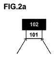
本発明の第1の好ましい実施形態によれば、本発明による光電子装置が、添付の図面によって説明される。より具体的には、図1に、小型分光計102を備える光電子装置100が示されており、この分光計102が、光導入部と、この光導入部と外部との間に配置され、環境光から分光計102の光導入部へと結合する光束を最大にするような方法で設計された第1の結合レンズ101とを備えている。
According to a first preferred embodiment of the present invention, an optoelectronic device according to the present invention is illustrated by the attached drawings. More specifically, FIG. 1 shows an
さらに、この実施形態によれば、分光計102およびその結合レンズ101が、LEDアレイをLEDパネル103(より具体的には、プリント基板またはPCB)に埋め込んで備えているパネルの中央に配置されている。この位置は、光導入部およびレンズ101の光軸がLEDパネル103によって発せられる光(すなわち、光の角度分布の対称軸)と同じ方向を向き、したがってLEDによって照明される領域の少なくとも一部分の環境光を捕捉するため、最適である。LEDのPCB103によって発せられた光が、対象物および特定の領域の表面に衝突し、この反射または散乱光の一部が、結合レンズ101を介して分光計102によって再び捕捉され、集められた光を分析することによって周囲の抽出情報を抽出することができる(周辺光の調査)。結合レンズ101は、考慮中の空間に存在するLEDパネル103とは異なる他の光源からの光も、直線的な光路を辿ることにより、あるいは空間内での1回または複数回の反射の後で、結合させる可能性がある。このようにして、本発明において示される光電子装置に類似または非類似のさまざまな光源(例えば、自然光または人工光)から出る光子が、結合レンズによって集められる結果となりうる。
Furthermore, according to this embodiment, the
分光計101およびそのレンズ102の配置は、光電子装置について意図される用途に応じ、あるいは各々の装置の機能に応じ、もしくは装置が領域内にどのように分布させられるかに応じて、さまざまであってよく、したがって各々の装置が、システムにおいて異なる方法で制御される。分光計102の配置の変種を示す他の実施形態が、さらなる図によって後述される。
The arrangement of
分光計102は、この例ではナノインプリントによる格子を備えるマイクロ分光計であるCMOS型のマイクロチップにて具現化されるが、そのような格子をマイクロチップ内に具現化できる幅広くさまざまな技術が存在し、それらも適切でありうる。適切なマイクロ分光計の市販の例は、Hamamatsu TMによって製造される新型の一連のマイクロチップに具現化された分光計であってよい。
In this example, the
さらに、装置100は、自身のLEDパネル103または他の光源によって発せられる光104を変更するための手段を備えている。そのような手段は、分光計からの信号をマイクロコントローラによる処理に適した電気信号へと調整するための手段を備える電子マイクロコントローラにおいて具現化される。また、マイクロコントローラまたは専用の電子機器が、小型分光計によって読み出される光スペクトルを受信して調整し、一連の規則に従い、種々の状況および装置について意図される用途に応じて、電子ドライバを通じて適切な電流を送ることによってLEDパネル103の一部または全体の発光を変更することができる。マイクロコントローラの最適化アルゴリズムが、所望の全体としての発光のスペクトルを得るために1つ1つのLEDに必要な電流を(較正表を読み取ることによって)決定することができる。この発光のスペクトルは、すべての個別のLEDの光スペクトルの合計である。
Furthermore, the
LEDパネル103に埋め込まれたLEDアレイは、電磁スペクトルの特定の部分をそれぞれ発することができるいくつかのLEDを備えることで、可視光または不可視光あるいは両方の組み合わせを含むことができる特定の用途のスペクトル範囲の全体をカバーする。これは、特定のスペクトル成分を発しなければならない場合に、所望のスペクトルを得るためにシステムが各々のLEDの発光の強度を変化させることができるため、有用である。したがって、多数のLED(典型的には、5〜50個の間の範囲)が使用され、この数が多いほど、任意の光スペクトルをより正確に再現することができる。最良の均質性および測光特性を達成するために、LED PCB103を、レンズおよびディフューザを備えるさらなる光学系に取り付けることができる。
The LED array embedded in the
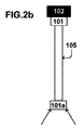
図2Aに詳しく見て取ることができるように、分光計102およびレンズ101を、図1の構成に示されるように周辺光を結合させるために、直接接触の状態に保持することができる。図2Bに示されるように、光ファイバ105の形態の導波路が一端においてレンズ101へと取り付けられ、他端において元のレンズ101と同様のさらなるレンズ101aへと取り付けられる別のより高度な構成も可能である。この方法で、所望の環境光を得るために分光計102およびレンズ101を同じ場所に配置する必要がなく、光ファイバが可撓であるがゆえに、第2のレンズ101aおよび第2のレンズ101aへと取り付けられたファイバの端部だけを所望の表面に配置しながら、ファイバの開口数および光学系全体のラグランジュの不変量に応じて、先の図2Aの代案と同等またはより高いレベルの結合束を受け取ることができる。
As can be seen in detail in FIG. 2A, the
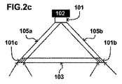
別の代案は、1つではなくて2つの光ファイバ105a、105bがハウジング内に配置され、一端が第1のレンズ101へと取り付けられ、他端が2つのさらなるレンズ101b、101cへと取り付けられている図2cに示される代案であってよい。これらのレンズが、ほぼLEDアレイと同じ平面に配置される一方で、分光計102を、結合レンズ101bおよび101cからさらに遠くに配置することができる。この方法で、光電子装置のより良好なカプセル化が達成され、考慮中の空間内の異なる領域または方向から到来する光を集めるために、可動の結合要素105、105a、105b、101a、101b、101cを備えるさらなる構成も可能になる。これらの可動の部品も、マイクロコントローラによって制御することができる。
Another alternative is to place two
このカプセル化を、図2cに示した光ファイバの構成を電子ブロック106とともに備える光電子装置100のパッケージングを示している図3においてよりよく見て取ることができる。
This encapsulation can be seen better in FIG. 3, which shows the packaging of the
この構成においては、レンズ101bおよび101cによって集められた光子が、レンズ101を介して分光計102へと結合させられる。小型分光計102が、これらの光子をそれらのエネルギに従って分類し、得られた光子分布(スペクトル)を表わす電子信号をもたらすことができる。随意による信号調整電子ブロック106aが、分光計102とマイクロコントローラ106bとの間で信号および動作モード(例えば、読み出しプロセスの積分時間、CMOSセンサの感度または利得、など)を調整するために必要であるかもしれない。マイクロコントローラ106bが、ひとたびスペクトル情報が読み出されたならば、専用のアルゴリズムによって特定のスペクトルパラメータを計算し、後にLEDアレイ103のスペクトル出力を変化させる電子ドライバ106cにより、さらには/あるいは例えばパラメータまたは前もって保存された情報をネットワークを介して送信する通信/保存ブロック106dによって、行動することができる。当然ながら、スタンドアロンの装置用の電池および/またはコンセントに差し込まれる装置用の電流整流器で構成される最終的なパワーエレクトロニクスブロック(単純にするために図面からはあえて省略されている)も、必要であると考えられる。
In this configuration, photons collected by
さらに、図3に示した装置は、図2に示した光結合の構成のいずれにおいても、多数の光ファイバが結合レンズ101(一部は可動であってもよい)へと結合されても、普遍性を失うことなく機能することができる。あるいは、本発明の技術的範囲を限定することなくさらなる機能をもたらすために、温度センサ、湿度センサ、気流速度センサ、光強度センサ(シリコン、太陽電池、など)、イメージ(CMOSまたはCCDアレイ)センサなど、他のセンサを容易に統合することができる。 Furthermore, in the apparatus shown in FIG. 3, in any of the optical coupling configurations shown in FIG. 2, even if a large number of optical fibers are coupled to the coupling lens 101 (some of which may be movable) It can function without losing universality. Alternatively, a temperature sensor, a humidity sensor, an airflow rate sensor, a light intensity sensor (silicon, solar cell, etc.), an image (CMOS or CCD array) sensor to provide further functions without limiting the technical scope of the present invention. Other sensors can be easily integrated.
図4が、光電子装置のベースを示しており、LEDパネル103およびLEDパネル103における複数のLED203の典型的な配置が示されている。任意のスペクトルを再現することができる複数の発光体203を含んでいる基本セルが、全体としての発光の放射(不可視の用途)または照明(可視の用途)の力を高めるために、周期的に複製されている。同時に、この複製は、出力される光の色およびスペクトルの均質性の向上をもたらす。
FIG. 4 shows the base of the optoelectronic device and shows a typical arrangement of the
さらなる好ましい実施形態によれば、図5が、領域500の環境光を変更するためのシステムであって、複数の光電子装置100a〜100dを備えており、光電子装置100a〜100dのLEDパネル103a〜d(103aだけが標記されている)が部分領域301a〜301dをカバーしており、光電子装置100a〜100dの小型分光計102a〜d(102aだけが標記されている)が部分領域300a〜300dをカバーしているシステムを示している。
According to a further preferred embodiment, FIG. 5 is a system for changing ambient light in
この特定の状況に見て取ることができるとおり、各々の装置のLEDパネルによって発せられる光の円すい(部分領域301a〜301d)が、302のように互いに部分的に重なり合っている。同じ方法で、各々の分光計の「検出」の円すい(部分領域300a〜300d)が、303のように隣の装置が発する光の円すいと重なり合っている。 As can be seen in this particular situation, the cones of light (partial regions 301 a-301 d) emitted by the LED panels of each device partially overlap each other as 302. In the same way, the “detection” cone (partial region 300a-300d) of each spectrometer overlaps with the cone of light emitted by the adjacent device, such as 303.
この方法で、装置が「コピーモード」にプログラムされている(すなわち、LEDアレイの発光を変更するための手段が、同じ装置の分光計によって得られた光スペクトルに正確に一致する光を発するようにプログラムされている)とき、装置の分光計によってカバーされる部分領域のうちの1つにおいて光スペクトルに外的な変化または動揺が生じると、該当の装置が前記変化を検出し、検出された光スペクトルを有する光を発し始める。次いで、そのLEDアレイによってカバーされる領域が、他の装置の分光計によって検出され、結果として、これら他の装置が新たな光スペクトルを取得して、この新たな光スペクトルを有する光を発し始め、したがって元の動揺をすべての装置によってカバーされる領域の全体へと広げ、この最初の変化または動揺に応答した新規な環境光を達成する連鎖反応が生じる。 In this way, the device is programmed to “copy mode” (ie, the means for changing the emission of the LED array emit light that exactly matches the light spectrum obtained by the spectrometer of the same device. When an external change or perturbation in the light spectrum occurs in one of the partial areas covered by the spectrometer of the device, the device detects and detects that change. It begins to emit light having a light spectrum. The area covered by the LED array is then detected by the spectrometer of the other device, and as a result, these other devices acquire a new light spectrum and begin to emit light with this new light spectrum. Thus, a chain reaction occurs that spreads the original sway over the entire area covered by all devices and achieves a new ambient light in response to this initial change or sway.
システムの領域の一部分の光スペクトルの前記変化(1つの装置によって検出することができる)は、領域外から到来する光の変化(例えば、太陽光、別の空間から到来する人工光の点滅、など)によって引き起こされても、意図的に行なわれる変化(誰かが分光計へと懐中電灯を向ける)によって引き起こされても、あるいは例えば部屋への人々の進入またはその部屋での人々の移動によって引き起こされてもよい。 The change in the light spectrum of one part of the system area (which can be detected by one device) is a change in light coming from outside the area (eg sunlight, blinking artificial light coming from another space, etc.) ), Caused by intentional changes (someone directs a flashlight to the spectrometer) or caused by people entering or moving in the room, for example May be.
また、環境光の変化を、特定の光電子装置のLEDのアレイの発光のプログラムされた変化(すなわち、例えば1日のうちの特定の時刻において実行されるようにユーザによってプログラムされてあらかじめ保存された光スペクトルでの発光)によって引き起こすこともでき、システムのただ1つの装置の発光だけを単に自動的に変化させるだけで、連鎖反応および領域の環境光の全体の変化を可能にすることができる。 Also, changes in ambient light are programmed and pre-stored by the user to be performed at a particular time of the day, for example, a programmed change in the light emission of an array of LEDs of a particular optoelectronic device. (Emission in the light spectrum), and can simply change the emission of only one device of the system automatically, allowing the chain reaction and the overall change in the ambient light of the region.
当然ながら、システムの装置を、装置間で異なってプログラムすることができ、装置の一部を静的(スペクトルが変化しても発光が変わらない)にし、他の一部を変更可能(例えば、上述の「コピーモード」にて機能する)にすることができる。 Of course, the system's devices can be programmed differently between devices, making some of the devices static (the emission does not change when the spectrum changes) and others can be changed (e.g. Function in the above-mentioned “copy mode”).
このシステムについて考えられる用途は、例えば、窓に近い装置から建物の内部への昼光照明の状況についての情報の伝達であってよい。 A possible application for this system may be, for example, the transmission of information about the daylighting situation from a device close to the window to the interior of the building.
他の用途として、インテリジェントな照明環境と人間とのやり取りが挙げられ、人間の表現が、環境において所望の客観的状態または感情的状態を達成するために、インテリジェントなシステムへの入力として有効な役割を果たす。 Another application is the interaction of humans with intelligent lighting environments, where human expressions serve as an effective input to intelligent systems to achieve the desired objective or emotional state in the environment. Fulfill.
さらなる例として、インタラクティブなゲームが挙げられる。例えば、異なる色の懐中電灯を有するユーザが、自身の懐中電灯またはトーチを装置へと向けることによって領域の全体的な照明を変化させなければならず、領域のすべての光を自身の色へと変えたチームが勝者となるゲームである。 A further example is an interactive game. For example, a user with a different color flashlight must change the overall illumination of the area by directing his flashlight or torch to the device, and all the light in the area into his color In this game, the changed team is the winner.
本発明のさらなる実施形態は、複数の光電子装置をすでに述べたシステムのように配置して備えており、発光体の各々の固有波長が通信チャネルを呈しているシステムであってよい。この意味で、ユーザまたはコンピュータプログラムが、特定の光電子装置を発光体として機能するように制御することができ、チャネル数は、異なる固有波長を有する発光体の数によって決まり、各々の信号チャネルにおいて、あらゆる種類のデジタル、多論理、またはアナログ通信プロトコルが可能である。この方法で、残りの光電子装置が、自身の分光計によってこれらのスペクトル成分を受信し、同じ光スペクトルを有する光を再現することによって他の装置への同じ情報の伝達を続けることができ、あるいは各々の通信チャネルに含まれる情報をデコードすることによって情報を解読し、必要な動作を行なうことができる。 A further embodiment of the present invention may be a system comprising a plurality of optoelectronic devices arranged as in the system already described, wherein each intrinsic wavelength of the light emitter presents a communication channel. In this sense, a user or computer program can control a particular optoelectronic device to function as a light emitter, the number of channels being determined by the number of light emitters having different natural wavelengths, and in each signal channel, Any kind of digital, multi-logic or analog communication protocol is possible. In this way, the rest of the optoelectronic device can receive these spectral components with its spectrometer and continue to transmit the same information to other devices by reproducing light having the same optical spectrum, or By decoding the information contained in each communication channel, the information can be decoded and necessary operations can be performed.
この方法で、情報を発光の光スペクトルにエンコードする(すなわち、1つ1つのLEDの固有波長を通信チャネルとして使用することによってエンコードする)ことができ、前記第1の光電子装置によって発せられたときに、発光を他の光電子装置によって検出することができ、それらが「コピーモード(装置が或る光スペクトルを取得し、自身のLEDアレイで同じ光スペクトルを発する)」に設定されている場合、連鎖反応が引き起こされ、エンコードされた情報を含む光スペクトルが、他の光電子装置による発光−コピーの連鎖によって送信される。 In this manner, information can be encoded into the light spectrum of emitted light (ie, encoded by using the unique wavelength of each LED as a communication channel) and when emitted by the first optoelectronic device. In addition, if the emission can be detected by other optoelectronic devices and they are set to “copy mode (the device acquires a certain light spectrum and emits the same light spectrum in its own LED array)”, A chain reaction is triggered and the light spectrum containing the encoded information is transmitted by a light emitting-copy chain by other optoelectronic devices.
本発明のさらなる実施形態においては、システムが、システムのすべての光電子装置へと接続されたコンピュータサーバを備える。この接続(ケーブルを介する通信ネットワーク、無線、またはコンピュータデバイス間の任意の他の適切な種類の通信による)は、光電子装置が自身の該当の領域において検出される光スペクトルの変化に対応する情報を前記サーバへと送信し、任意の光電子装置によって実行されるべき動作をサーバに制御させることを可能にする。コンピュータサーバによって行なわれる決定は、1日における時刻または他の関連情報(例えば、他の光電子装置、他のセンサ、などにおいて以前に検出されたスペクトル変化に対応する履歴情報)などの他の入力を含むことができる。 In a further embodiment of the invention, the system comprises a computer server connected to all optoelectronic devices of the system. This connection (via a communication network via cable, wireless, or any other suitable type of communication between computer devices) allows information that corresponds to changes in the optical spectrum that optoelectronic devices detect in their respective areas. Sends to the server and allows the server to control operations to be performed by any optoelectronic device. Decisions made by the computer server may include other inputs such as time of day or other relevant information (eg, historical information corresponding to spectral changes previously detected in other optoelectronic devices, other sensors, etc.). Can be included.
この方法で、システムを、コンピュータサーバを介して、同じ種類であってよく、あるいは同じ種類でなくてもよい他のシステムへと接続することができる。そのような追加のシステムは、センサネットワーク、マイクログリッド、インターネット、他のコンピュータサーバ、あるいは関心の他の電子装置または通信ネットワークを含むことができる。 In this way, the system can be connected via a computer server to other systems that may or may not be of the same type. Such additional systems can include sensor networks, microgrids, the Internet, other computer servers, or other electronic devices or communication networks of interest.
さらに、光電子装置が互いに通信することもでき、例えば異なる種類の光電子装置を他の光電子装置を制御するようにプログラムし、サーバの使用と他の光電子装置によって実行されるべき動作も制御することができる光電子装置とを組み合わせることができ、これは、システムについて意図される用途、1つ以上の領域における装置の位置、などに応じて好ましい可能性がある。 In addition, the optoelectronic devices can communicate with each other, for example, programming different types of optoelectronic devices to control other optoelectronic devices, and controlling the use of the server and the operations to be performed by the other optoelectronic devices. Can be combined with possible optoelectronic devices, which may be preferred depending on the intended use for the system, the position of the device in one or more regions, etc.
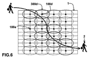
システムのさらなる用途の例が、図6に示される本発明の実施形態であり、本発明による複数の光電子装置(装置100dまたは100eなど)を備えるシステムが、領域1に、この領域において人々または物体の追跡し、随意により相応に適切な光を発し、さらには/あるいはさらなる装置またはコンピュータサーバへと情報を送信することを目的として、各々の装置100dの分光計の範囲300dの合計によって実質的に領域の全体を覆うように配置されている。より具体的には、先の実施形態において見られるように、分光計の範囲300dが互いに部分的に重なり合っており、システムにおいて、人間2が或る範囲から別の範囲へと領域1を通過したならば、重なり合いの領域ゆえに両方の装置が人間を検出し、所定のスペクトル成分を有する所定の光を発し、あるいはこの情報をさらなる処理のために送信することができる。この処理は、コンピュータプログラムにもとづく個人または人物の特定を含むことができる。コンピュータアルゴリズムは、1つ以上の光電子装置(すなわち、分散プログラミング)および/またはコンピュータサーバに含まれてよい。パターン認識を実行するために、アルゴリズムは、ニューラルネットワーク、ファジー論理、および/または他の先進のコンピュータパラダイムなどのソフトコンピューティングにもとづく技術を含むことができる。
An example of a further use of the system is the embodiment of the present invention shown in FIG. 6, where a system comprising a plurality of optoelectronic devices (such as
例えば、装置100dの範囲300d内の人物を検出するために、その特定の人物について受信されたスペクトル成分にもとづく所定のパターンが保存される。次いで、このパターンがシステムによってあらかじめ保存されたデータベースに存在する人物または物体であると認識されると、特定を知らせる信号または他の情報を、ネットワークを通じて他の光電子装置またはサーバへと送信することができ、他の光電子装置またはサーバが必要な動作を行なうことができる。
For example, to detect a person within
この情報は、例えば追跡対象のユーザについてあらかじめ設定される照明の状態に関連できる特定のスペクトル成分を有する光を再現するために、他の装置に対して特定の光を発するように要求する一連の指示を含むことができ、あるいはLEDを制御するドライバへと直接送信されてもよい。 This information is a series of requests that require other devices to emit specific light, for example, to reproduce light having specific spectral components that can be related to preset lighting conditions for the tracked user. An indication can be included, or it can be sent directly to the driver controlling the LED.
さらに、前記情報は、例えば、衣服のさまざまな種類の色、特定の様相で光を反射する衣服の種類、人間の皮膚または髪の反射の種類、などによって反射される光に対応するスペクトルの特徴を含むことができる。 Furthermore, the information may include spectral features corresponding to light reflected by, for example, various types of clothing colors, types of clothing that reflect light in a particular manner, types of reflection on human skin or hair, etc. Can be included.
さらに、物体または人物の移動を、スペクトルの変化の速さや、或る種類から別の或る種類への変化であるか否かなど、他の特徴を加えて検出することもできる。情報を、特定の空間において異なる光電子装置が得たスペクトルを比較することによって集めることもできる。光電子装置および追加のコンピュータサーバの間で通信ポートを介して情報を共有するこの方法は、照明システムが設置された空間の全体において生じる変化を追跡するうえで役に立つことができる。 Furthermore, the movement of an object or a person can be detected by adding other characteristics such as the speed of change of the spectrum and whether or not it is a change from one type to another type. Information can also be gathered by comparing spectra obtained by different optoelectronic devices in a particular space. This method of sharing information between the optoelectronic device and the additional computer server via the communication port can be useful in tracking changes that occur throughout the space in which the lighting system is installed.
このシステムの用途は、すべての装置が弱く発光し、あるいは発光しておらず、移動している物体または人物が特定の光電子装置の下方を通過するときに、この光電子装置の発光が快適な照明レベルに切り換わることで、通過する人物の経路を照明する用途である。光電子装置の読み出しの範囲が互いに重なり合っているため、人物の前方の経路が照明される(図において見られるように、例えば装置100dおよび範囲が太線で示されている装置によって照明される)とともに、人物の背後または人物から遠い経路を照明する光(図において見られるように、例えば装置100eおよび範囲が細い線で示されている装置)が減光され、したがって領域のうちの人物に隣接する部分(および、人物の歩行の進路に対応する部分)だけが照明され、全体としてのプロセスにおけるエネルギを節約することができる構成を実現することができる。
The application of this system is that all devices are weakly lit or not lit, and the light emission of this optoelectronic device is comfortable when a moving object or person passes under a certain optoelectronic device By switching to a level, it is an application that illuminates the route of a passing person. Since the readout range of the optoelectronic device overlaps each other, the path ahead of the person is illuminated (as seen in the figure, for example by the
人工ニューラルネットワークが、80年代における復興以来、多くの用途において使用されている。その最も一般的な使用例は、パーソナルコンピュータまたはワークステーションにおいて動作するプログラムであり、ユーザがそれらの用途の要件に応じてネットワークの接続形態、処理要素の種類、または学習の規則を容易に変更することができるそのソフトウェアの高い柔軟性ゆえに幅広く使用されている。 Artificial neural networks have been used in many applications since the reconstruction in the 80s. The most common use case is a program that runs on a personal computer or workstation, where users can easily change the network topology, type of processing elements, or learning rules according to their application requirements. It can be widely used because of its high software flexibility.
しかしながら、逐次処理コンピュータにおけるニューラルネットワークの実現は、人工ニューラルネットワークの起源である生物学的なニューラルネットワークが高度に並列に動作するため、きわめて逆説的になると思われる。 However, the realization of a neural network in a sequential processing computer would be extremely paradoxical because the biological neural network that is the origin of the artificial neural network operates in a highly parallel manner.
高度に並列なニューラルシステムへのステップは、複数の処理要素(ニューロン)の利用である。この意味で、光電子装置からなるシステムは、そのような並列コンピューティングへの手法を実行するために好適となりうる。 The step to a highly parallel neural system is the use of multiple processing elements (neurons). In this sense, a system consisting of optoelectronic devices may be suitable for performing such a parallel computing approach.
本発明のさらに別の実施形態においては、光電子装置からなるシステムにおける並列コンピューティングの使用を、空間内に分布した複数の光電子装置がニューラルネットワークのノード(人工ニューロン)として機能するニューラルネットワークの生成において具現化することができる。ノード間の接続または通信を、ノード間の通信ネットワークによって実行でき、あるいはすでに述べたように、エンコードされた情報を光スペクトル内に含んでいる光によって実行することができる。この意味で、そのようなシステムにおいては、ニューラルネットワークにおいて普通に使用される非線形、分散、並列、かつローカルな処理および調整の原理を、容易に実現することができる。 In yet another embodiment of the invention, the use of parallel computing in a system of optoelectronic devices is used to generate a neural network in which a plurality of optoelectronic devices distributed in space function as neural network nodes (artificial neurons). Can be embodied. The connection or communication between the nodes can be performed by a communication network between the nodes or, as already mentioned, can be performed by light containing encoded information in the optical spectrum. In this sense, in such a system, the principles of non-linear, distributed, parallel and local processing and tuning commonly used in neural networks can be easily realized.
さらに、ニューラルネットワークに、情報処理のための数学的モデルまたは計算モデルが備えられる。計算モデルを、各々の光電子装置のマイクロコントローラによって保存および/または実行でき、さらには/あるいは複数の光電子装置へと分散させることができ、もしくはパーソナルコンピュータなどの通信ポートを通じて中央演算処理装置によって制御することもできる。 Furthermore, the neural network is provided with a mathematical model or a calculation model for information processing. The computational model can be stored and / or executed by each optoelectronic device microcontroller and / or distributed to multiple optoelectronic devices or controlled by a central processing unit through a communication port such as a personal computer. You can also
本発明を例示の目的で詳しく説明したが、そのような詳細があくまでも説明の目的のためのものにすぎず、当業者であれば本発明の技術的範囲から離れることなく変更を行なうことが可能であることを、理解すべきである。 Although the present invention has been described in detail for purposes of illustration, such details are for illustrative purposes only and modifications can be made by those skilled in the art without departing from the scope of the invention. It should be understood that.
すなわち、方法およびシステムの好ましい実施形態を、それらの開発の環境を参照して説明したが、それらは本発明の原理の例示にすぎない。他の実施形態および構成を、添付の特許請求の範囲の技術的範囲から離れることなく、考え出すことが可能である。 That is, although preferred embodiments of the method and system have been described with reference to their development environment, they are merely illustrative of the principles of the present invention. Other embodiments and configurations can be devised without departing from the scope of the appended claims.
さらに、図面を参照して説明した本発明の実施形態は、コンピュータ装置およびコンピュータ装置において実行されるプロセスを含んでいるが、本発明は、本発明を実行するように構成されたコンピュータプログラム(とくには、担体上または担体内のコンピュータプログラム)にも広がる。プログラムは、ソースコード、オブジェクトコード、あるいは途中までコンパイルされた形態などのコード中間ソースおよびオブジェクトコードの形態であってよく、もしくは本発明によるプロセスの実行において使用するために適した任意の他の形態であってよい。担体は、プログラムを保持することができる任意の実体または装置であってよい。 Further, although the embodiments of the present invention described with reference to the drawings include a computer device and a process executed on the computer device, the present invention is not limited to a computer program (particularly a computer program configured to execute the present invention). Extends to computer programs on or in the carrier. The program may be in the form of source code, object code, or code intermediate source and object code, such as a partially compiled form, or any other form suitable for use in performing the process according to the invention. It may be. A carrier may be any entity or device capable of holding a program.
例えば、担体は、ROM(例えば、CD ROMまたは半導体ROM)などの記憶媒体、あるいは例えばフロッピーディスクまたはハードディスクなどの磁気記録媒体を含むことができる。さらに、担体は、電気または光ケーブルあるいは無線または他の手段によって伝達することができる電気または光信号などの送信可能な媒体であってよい。 For example, the carrier can include a storage medium such as a ROM (eg, CD ROM or semiconductor ROM) or a magnetic recording medium such as a floppy disk or hard disk. Further, the carrier may be a transmissible medium such as an electrical or optical cable or an electrical or optical signal that can be transmitted by radio or other means.
プログラムが、ケーブルあるいは他の装置または手段によって直接伝達することができる信号に具現化される場合、担体を、そのようなケーブルあるいは他の装置または手段によって構成することができる。 If the program is embodied in a signal that can be transmitted directly by a cable or other device or means, the carrier can be constituted by such a cable or other device or means.
あるいは、担体が、プログラムが組み込まれており、関連のプロセスを実行するように構成され、あるいは関連のプロセスの実行に使用されるように構成された集積回路であってもよい。 Alternatively, the carrier may be an integrated circuit in which a program is incorporated and configured to execute an associated process, or configured to be used to perform an associated process.
Claims (21)
前記周囲の前記領域内の環境光の光スペクトルを取得するように配置されたCMOSベースの小型分光計と、
前記取得される光スペクトルにもとづいて前記発光体の発光を変更するための制御手段と
を備え、前記CMOSベースの小型分光計がCMOS技術を使用して製造された光分散のための格子を有することを特徴とする光電子装置。 A plurality of light emitters arranged to illuminate a surrounding area;
A small CMOS-based spectrometer arranged to acquire an optical spectrum of ambient light in the surrounding region;
Control means for changing the light emission of the light emitter based on the acquired light spectrum, and the CMOS-based miniature spectrometer has a grating for light dispersion manufactured using CMOS technology An optoelectronic device.
前記第1または第2の光学要素を移動させるための手段をさらに備えている請求項7に記載の光電子装置。 The first or second optical element is movable;
8. The optoelectronic device according to claim 7, further comprising means for moving the first or second optical element.
請求項1〜8のいずれか一項に記載の少なくとも2つの光電子装置と、
該光電子装置の間で情報を伝送するための手段と
を備えるシステム。 A system for changing ambient light in an area,
At least two optoelectronic devices according to any one of the preceding claims;
Means for transmitting information between the optoelectronic devices.
少なくとも第2の光電子装置が、取得された光スペクトルに対応する光スペクトルパラメータを受信するための手段と、受信されたパラメータにもとづいて自身の発光体の発光を変更するための手段とをさらに備えている、
請求項9に記載の或る領域の環境光を変更するためのシステム。 At least the first optoelectronic device further comprises means for acquiring an optical spectral parameter corresponding to the acquired optical spectrum and means for transmitting the optical spectral parameter to a further optoelectronic device;
At least the second optoelectronic device further comprises means for receiving an optical spectrum parameter corresponding to the acquired optical spectrum and means for changing the light emission of its light emitter based on the received parameter. ing,
10. A system for changing an area of ambient light according to claim 9.
前記第1の光電子装置の小型分光計によって前記環境光からの光スペクトルを取得するステップと、
前記第1の光電子装置によって前記取得された光スペクトルに対応するパラメータを取得するステップと、
前記取得されたパラメータを前記第1の光電子装置から前記第2の光電子装置へと送信するステップと
を含む方法。 16. A method for changing an area of ambient light in a system according to any one of claims 9-15 comprising first and second optoelectronic devices comprising:
Obtaining a light spectrum from the ambient light by a small spectrometer of the first optoelectronic device;
Obtaining a parameter corresponding to the obtained optical spectrum by the first optoelectronic device;
Transmitting the obtained parameter from the first optoelectronic device to the second optoelectronic device.
前記発光体によって照明することができる環境の領域内に前記反射装置の少なくとも一部分を配置するステップと、
前記複数の発光体によって予想光スペクトルを有する光を発するステップと、
前記小型分光計によって、前記反射装置で反射された発光から実光スペクトルを取得するステップと、
前記取得された実光スペクトルと、前記発せられた予想光スペクトルに対応する予想反射光スペクトルとの間の類似度パラメータを取得するステップと、
前記類似度パラメータにもとづいて前記光電子装置の較正を決定するステップと
を含む方法。 A method for determining calibration of an optoelectronic device according to any one of claims 1 to 8 by a reflector device according to claim 20.
Placing at least a portion of the reflector in a region of the environment that can be illuminated by the light emitter;
Emitting light having an expected light spectrum by the plurality of light emitters;
By the small spectrometer acquiring actual optical spectrum from the anti-Isa light emitting by the reflection device,
Obtaining a similarity parameter between the acquired actual light spectrum and an expected reflected light spectrum corresponding to the emitted expected light spectrum;
Determining calibration of the optoelectronic device based on the similarity parameter.
Applications Claiming Priority (1)
| Application Number | Priority Date | Filing Date | Title |
|---|---|---|---|
| PCT/EP2011/050002 WO2012092956A1 (en) | 2011-01-03 | 2011-01-03 | Optoelectronic device, system and method for obtaining an ambient light spectrum and modifying an emitted light |
Publications (3)
| Publication Number | Publication Date |
|---|---|
| JP2014508377A JP2014508377A (en) | 2014-04-03 |
| JP2014508377A5 JP2014508377A5 (en) | 2014-07-24 |
| JP5745644B2 true JP5745644B2 (en) | 2015-07-08 |
Family
ID=44624965
Family Applications (1)
| Application Number | Title | Priority Date | Filing Date |
|---|---|---|---|
| JP2013546618A Expired - Fee Related JP5745644B2 (en) | 2011-01-03 | 2011-01-03 | Optoelectronic device, system, and method for obtaining ambient light spectrum and changing emission |
Country Status (13)
| Country | Link |
|---|---|
| US (1) | US9420666B2 (en) |
| EP (1) | EP2604094B1 (en) |
| JP (1) | JP5745644B2 (en) |
| KR (1) | KR20130143102A (en) |
| CN (1) | CN103299717B (en) |
| AU (1) | AU2011354248B2 (en) |
| BR (1) | BR112013017113A2 (en) |
| CA (1) | CA2822911C (en) |
| DK (1) | DK2604094T3 (en) |
| ES (1) | ES2514323T3 (en) |
| PL (1) | PL2604094T3 (en) |
| RU (1) | RU2565241C2 (en) |
| WO (1) | WO2012092956A1 (en) |
Families Citing this family (18)
| Publication number | Priority date | Publication date | Assignee | Title |
|---|---|---|---|---|
| KR100243464B1 (en) * | 1996-08-23 | 2000-02-01 | 전주범 | Dpcm of mpeg-2 |
| US9288865B2 (en) * | 2012-02-13 | 2016-03-15 | Lumenetix, Inc. | Expert system for establishing a color model for an LED-based lamp |
| US9910828B2 (en) | 2013-03-12 | 2018-03-06 | Qualcomm Incorporated | Spectrometer for personal context |
| DE102015200133A1 (en) | 2015-01-08 | 2016-07-14 | Tridonic Gmbh & Co Kg | Lighting system with presence detection of persons |
| DE202016008522U1 (en) | 2015-06-08 | 2018-05-22 | Opple Lighting Co. Ltd. | Lighting device and control system for it |
| WO2016197903A1 (en) | 2015-06-08 | 2016-12-15 | 欧普照明股份有限公司 | Illumination device and control method and control system therefor |
| CN105101535B (en) * | 2015-06-08 | 2018-02-09 | 欧普照明股份有限公司 | Lighting device and its control method and control system |
| DE202016008535U1 (en) * | 2015-06-08 | 2018-04-19 | Opple Lighting Co. Ltd. | Intelligent lighting system and control method for it |
| CN106326983B (en) * | 2015-06-25 | 2020-01-07 | 江苏灵云数据科技有限公司 | Photoelectric conversion implementation method and device for artificial neural network connection |
| US20170086676A1 (en) * | 2015-09-24 | 2017-03-30 | Johnson & Johnson Vision Care, Inc. | Quantum-dot spectrometers for use in biomedical devices and methods of use |
| US9736597B1 (en) * | 2016-02-17 | 2017-08-15 | Siemens Energy, Inc. | Optical fiber based microphone array for detecting acoustic emissions generated by an area of interest |
| CN109863833A (en) * | 2016-10-27 | 2019-06-07 | 昕诺飞控股有限公司 | For the method, equipment and system of the adapter tube light effect between lighting apparatus, wherein each equipment covers different overlay areas |
| EP3555597A4 (en) * | 2016-12-15 | 2020-08-26 | Gemological Institute of America, Inc. (GIA) | Device and method for screening gemstones |
| JP2017228547A (en) * | 2017-10-06 | 2017-12-28 | パイオニア株式会社 | Lighting system |
| DE102017221671A1 (en) * | 2017-12-01 | 2019-06-06 | Zumtobel Lighting Gmbh | Motion detection of persons using color sensors |
| US10859505B2 (en) * | 2018-01-26 | 2020-12-08 | Gemological Institute Of America, Inc. (Gia) | Fluorescence box for gemological applications |
| CN108225277A (en) * | 2018-03-09 | 2018-06-29 | 深圳臻迪信息技术有限公司 | Image acquiring method, vision positioning method, device, the unmanned plane of unmanned plane |
| UA118644C2 (en) | 2018-09-25 | 2019-02-11 | Василь Олександрович Руських | PORTABLE PORTABLE LIGHTING DEVICE FOR UNDERWATER PHOTOS AND VIDEOS |
Family Cites Families (28)
| Publication number | Priority date | Publication date | Assignee | Title |
|---|---|---|---|---|
| US5965873A (en) * | 1997-09-17 | 1999-10-12 | Lockheed Martin Energy Research Corporation | Integrated CMOS spectrometers |
| US7642730B2 (en) * | 2000-04-24 | 2010-01-05 | Philips Solid-State Lighting Solutions, Inc. | Methods and apparatus for conveying information via color of light |
| US6448550B1 (en) * | 2000-04-27 | 2002-09-10 | Agilent Technologies, Inc. | Method and apparatus for measuring spectral content of LED light source and control thereof |
| WO2003069290A1 (en) * | 2002-02-13 | 2003-08-21 | Fraunhofer-Gesellschaft zur Förderung der angewandten Forschung e. V. | Quasi-static deflection device for spectrometers |
| US7084973B1 (en) * | 2002-06-11 | 2006-08-01 | Dalsa Inc. | Variable binning CCD for spectroscopy |
| US7057735B2 (en) * | 2002-11-14 | 2006-06-06 | Fitel U.S.A. Corp. | Method for measuring the optical and physical thickness of optically transparent objects |
| US20060018118A1 (en) | 2004-07-21 | 2006-01-26 | Lee Joon C | Spectrum matching |
| US7345764B2 (en) * | 2005-02-07 | 2008-03-18 | Vladimir Bulovic | Apparatus and method for a slim format spectrometer |
| KR20080031722A (en) * | 2005-06-03 | 2008-04-10 | 코닌클리즈케 필립스 일렉트로닉스 엔.브이. | System and method for controlling a led luminary |
| CA2611565C (en) * | 2005-08-25 | 2012-04-17 | Institut National D'optique | Flow cytometry analysis across optical fiber |
| JP4600310B2 (en) * | 2006-02-16 | 2010-12-15 | エプソンイメージングデバイス株式会社 | Electro-optical device, drive circuit, and electronic apparatus |
| EP1862795A1 (en) * | 2006-05-10 | 2007-12-05 | ABB Schweiz AG | Bulk Material Analyzer System |
| US20100007491A1 (en) * | 2006-07-28 | 2010-01-14 | Koninklijke Philips Electronics N.V. | integrated image recognition and spectral detection device and a device and method for automatically controlling the settings of a light by image recognition and spectral detection of the light |
| JP4985061B2 (en) | 2007-04-06 | 2012-07-25 | 株式会社ニコン | Spectroscopic apparatus and imaging apparatus |
| DE102007044556A1 (en) * | 2007-09-07 | 2009-03-12 | Arnold & Richter Cine Technik Gmbh & Co. Betriebs Kg | Method and device for adjusting the color or photometric properties of an LED lighting device |
| DE102007042573A1 (en) * | 2007-09-07 | 2009-03-12 | Osram Opto Semiconductors Gmbh | Optical lighting device for use in optical recording device e.g. video camera, has control unit adjusting spectral characteristic of light emitted by light source based on determined spectral characteristic of environment light |
| WO2009034515A2 (en) * | 2007-09-11 | 2009-03-19 | Philips Intellectual Property & Standards Gmbh | Ambient light compensation sensor and procedure |
| FR2922304B1 (en) | 2007-10-12 | 2009-11-20 | Sp3H | SPECTROMETRY DEVICE FOR ANALYSIS OF A FLUID |
| US7595786B2 (en) * | 2007-11-13 | 2009-09-29 | Capella Microsystems, Corp. | Illumination system and illumination control method for adaptively adjusting color temperature |
| KR20100099183A (en) | 2007-11-20 | 2010-09-10 | 코닌클리즈케 필립스 일렉트로닉스 엔.브이. | Collimating light emitting apparatus and method |
| US7728984B2 (en) * | 2008-02-28 | 2010-06-01 | Inficon Gmbh | Method for evaluating a measured parameter |
| JP5111163B2 (en) * | 2008-03-04 | 2012-12-26 | 浜松ホトニクス株式会社 | Spectrometer |
| CN102084290A (en) | 2008-03-18 | 2011-06-01 | 皇家飞利浦电子股份有限公司 | Calibration camera with spectral depth |
| US8174695B2 (en) * | 2008-08-15 | 2012-05-08 | The United States Of America As Represented By The Administrator Of The National Aeronautics And Space Administration | Arrayed micro-ring spectrometer system and method of use |
| WO2010128435A1 (en) * | 2009-05-08 | 2010-11-11 | Koninklijke Philips Electronics N.V. | A circuit for and a method of sensing a property of light |
| DE202009011500U1 (en) * | 2009-08-20 | 2010-12-30 | Arnold & Richter Cine Technik Gmbh & Co. Betriebs Kg | Optical system for an LED light |
| US8492983B1 (en) * | 2010-05-11 | 2013-07-23 | Analog Technologies Corporation | System and method to address and control serially connected LEDs |
| WO2012012258A2 (en) * | 2010-07-21 | 2012-01-26 | First Solar, Inc. | Temperature-adjusted spectrometer |
-
2011
- 2011-01-03 RU RU2013136394/07A patent/RU2565241C2/en not_active IP Right Cessation
- 2011-01-03 EP EP11700007.5A patent/EP2604094B1/en not_active Not-in-force
- 2011-01-03 DK DK11700007.5T patent/DK2604094T3/en active
- 2011-01-03 ES ES11700007.5T patent/ES2514323T3/en active Active
- 2011-01-03 PL PL11700007T patent/PL2604094T3/en unknown
- 2011-01-03 CA CA2822911A patent/CA2822911C/en active Active
- 2011-01-03 KR KR1020137018669A patent/KR20130143102A/en not_active Application Discontinuation
- 2011-01-03 CN CN201180063762.0A patent/CN103299717B/en not_active Expired - Fee Related
- 2011-01-03 BR BR112013017113-8A patent/BR112013017113A2/en not_active Application Discontinuation
- 2011-01-03 JP JP2013546618A patent/JP5745644B2/en not_active Expired - Fee Related
- 2011-01-03 WO PCT/EP2011/050002 patent/WO2012092956A1/en active Application Filing
- 2011-01-03 US US13/978,134 patent/US9420666B2/en active Active
- 2011-01-03 AU AU2011354248A patent/AU2011354248B2/en not_active Ceased
Also Published As
| Publication number | Publication date |
|---|---|
| RU2013136394A (en) | 2015-02-10 |
| CA2822911A1 (en) | 2012-07-12 |
| DK2604094T3 (en) | 2014-10-06 |
| EP2604094B1 (en) | 2014-07-16 |
| CN103299717A (en) | 2013-09-11 |
| RU2565241C2 (en) | 2015-10-20 |
| AU2011354248B2 (en) | 2015-08-20 |
| AU2011354248A1 (en) | 2013-07-11 |
| CN103299717B (en) | 2015-11-25 |
| KR20130143102A (en) | 2013-12-30 |
| PL2604094T3 (en) | 2015-02-27 |
| WO2012092956A1 (en) | 2012-07-12 |
| US20130293116A1 (en) | 2013-11-07 |
| CA2822911C (en) | 2018-07-10 |
| ES2514323T3 (en) | 2014-10-28 |
| BR112013017113A2 (en) | 2020-10-27 |
| US9420666B2 (en) | 2016-08-16 |
| JP2014508377A (en) | 2014-04-03 |
| EP2604094A1 (en) | 2013-06-19 |
Similar Documents
| Publication | Publication Date | Title |
|---|---|---|
| JP5745644B2 (en) | Optoelectronic device, system, and method for obtaining ambient light spectrum and changing emission | |
| JP5587995B2 (en) | System and apparatus for automatically retrieving and correcting personal preferences applicable to multiple controllable lighting networks | |
| JP5572697B2 (en) | System and apparatus for image-based lighting control and security control | |
| US20210164623A1 (en) | Smart-home device light rings with tapered transmissive sections for uniform output | |
| JP4518793B2 (en) | Products based on light-emitting diodes | |
| RU2696003C2 (en) | Automatic actuation of lighting modules | |
| US20150145419A1 (en) | Methods and apparatus for automatically adapting light output of a lighting unit | |
| US20060226336A1 (en) | Apparatus and method for collecting and detecting light emitted by a lighting apparatus | |
| CN101932873A (en) | Methods and apparatus for providing led-based spotlight illumination in stage lighting applications | |
| CN101292573A (en) | A color lighting device | |
| US10753792B2 (en) | Reconfigurable optical fiber spectrometer in a lighting device | |
| CA2615706A1 (en) | Apparatus and method for collecting and detecting light emitted by a lighting apparatus | |
| US20230019044A1 (en) | Electronic Control Device | |
| US10156350B1 (en) | Methods and improvements to spectral monitoring of theatre lighting devices | |
| JP2014522485A (en) | Radiation sensing device, circuit | |
| CN109644540A (en) | Energy harvester as user interface | |
| US10111295B1 (en) | Methods and improvements to spectral monitoring of theatre lighting devices | |
| CN108781494A (en) | Method for characterizing target surface illumination | |
| CN108171186A (en) | A kind of fingerprint identification device and method | |
| TW201325308A (en) | Illumination control system and illumination control method | |
| TW201208476A (en) | Systems and apparatus for automatically deriving and modifying personal preferences applicable to multiple controllable lighting networks | |
| Park | Design and implementation of a wireless sensor network for intelligent light control | |
| JP2008216800A (en) | Lighting device and lighting system |
Legal Events
| Date | Code | Title | Description |
|---|---|---|---|
| A621 | Written request for application examination |
Free format text: JAPANESE INTERMEDIATE CODE: A621 Effective date: 20131225 |
|
| A521 | Request for written amendment filed |
Free format text: JAPANESE INTERMEDIATE CODE: A523 Effective date: 20140609 |
|
| A131 | Notification of reasons for refusal |
Free format text: JAPANESE INTERMEDIATE CODE: A131 Effective date: 20140924 |
|
| A521 | Request for written amendment filed |
Free format text: JAPANESE INTERMEDIATE CODE: A523 Effective date: 20141224 |
|
| TRDD | Decision of grant or rejection written | ||
| A01 | Written decision to grant a patent or to grant a registration (utility model) |
Free format text: JAPANESE INTERMEDIATE CODE: A01 Effective date: 20150407 |
|
| A61 | First payment of annual fees (during grant procedure) |
Free format text: JAPANESE INTERMEDIATE CODE: A61 Effective date: 20150501 |
|
| R150 | Certificate of patent or registration of utility model |
Ref document number: 5745644 Country of ref document: JP Free format text: JAPANESE INTERMEDIATE CODE: R150 |
|
| R250 | Receipt of annual fees |
Free format text: JAPANESE INTERMEDIATE CODE: R250 |
|
| S111 | Request for change of ownership or part of ownership |
Free format text: JAPANESE INTERMEDIATE CODE: R313113 |
|
| R350 | Written notification of registration of transfer |
Free format text: JAPANESE INTERMEDIATE CODE: R350 |
|
| R250 | Receipt of annual fees |
Free format text: JAPANESE INTERMEDIATE CODE: R250 |
|
| R250 | Receipt of annual fees |
Free format text: JAPANESE INTERMEDIATE CODE: R250 |
|
| R250 | Receipt of annual fees |
Free format text: JAPANESE INTERMEDIATE CODE: R250 |
|
| R250 | Receipt of annual fees |
Free format text: JAPANESE INTERMEDIATE CODE: R250 |
|
| LAPS | Cancellation because of no payment of annual fees |