JP5745634B2 - Method for designing and selecting an optical fiber for use with a transmitter optical subassembly - Google Patents
Method for designing and selecting an optical fiber for use with a transmitter optical subassembly Download PDFInfo
- Publication number
- JP5745634B2 JP5745634B2 JP2013534918A JP2013534918A JP5745634B2 JP 5745634 B2 JP5745634 B2 JP 5745634B2 JP 2013534918 A JP2013534918 A JP 2013534918A JP 2013534918 A JP2013534918 A JP 2013534918A JP 5745634 B2 JP5745634 B2 JP 5745634B2
- Authority
- JP
- Japan
- Prior art keywords
- multimode fiber
- fiber
- optic cable
- fiber optic
- dispersion
- Prior art date
- Legal status (The legal status is an assumption and is not a legal conclusion. Google has not performed a legal analysis and makes no representation as to the accuracy of the status listed.)
- Active
Links
Images


Classifications
-
- G—PHYSICS
- G01—MEASURING; TESTING
- G01M—TESTING STATIC OR DYNAMIC BALANCE OF MACHINES OR STRUCTURES; TESTING OF STRUCTURES OR APPARATUS, NOT OTHERWISE PROVIDED FOR
- G01M11/00—Testing of optical apparatus; Testing structures by optical methods not otherwise provided for
- G01M11/30—Testing of optical devices, constituted by fibre optics or optical waveguides
-
- G—PHYSICS
- G01—MEASURING; TESTING
- G01M—TESTING STATIC OR DYNAMIC BALANCE OF MACHINES OR STRUCTURES; TESTING OF STRUCTURES OR APPARATUS, NOT OTHERWISE PROVIDED FOR
- G01M11/00—Testing of optical apparatus; Testing structures by optical methods not otherwise provided for
-
- G—PHYSICS
- G01—MEASURING; TESTING
- G01M—TESTING STATIC OR DYNAMIC BALANCE OF MACHINES OR STRUCTURES; TESTING OF STRUCTURES OR APPARATUS, NOT OTHERWISE PROVIDED FOR
- G01M11/00—Testing of optical apparatus; Testing structures by optical methods not otherwise provided for
- G01M11/30—Testing of optical devices, constituted by fibre optics or optical waveguides
- G01M11/33—Testing of optical devices, constituted by fibre optics or optical waveguides with a light emitter being disposed at one fibre or waveguide end-face, and a light receiver at the other end-face
- G01M11/335—Testing of optical devices, constituted by fibre optics or optical waveguides with a light emitter being disposed at one fibre or waveguide end-face, and a light receiver at the other end-face using two or more input wavelengths
-
- G—PHYSICS
- G01—MEASURING; TESTING
- G01M—TESTING STATIC OR DYNAMIC BALANCE OF MACHINES OR STRUCTURES; TESTING OF STRUCTURES OR APPARATUS, NOT OTHERWISE PROVIDED FOR
- G01M11/00—Testing of optical apparatus; Testing structures by optical methods not otherwise provided for
- G01M11/30—Testing of optical devices, constituted by fibre optics or optical waveguides
- G01M11/33—Testing of optical devices, constituted by fibre optics or optical waveguides with a light emitter being disposed at one fibre or waveguide end-face, and a light receiver at the other end-face
- G01M11/338—Testing of optical devices, constituted by fibre optics or optical waveguides with a light emitter being disposed at one fibre or waveguide end-face, and a light receiver at the other end-face by measuring dispersion other than PMD, e.g. chromatic dispersion
-
- G—PHYSICS
- G02—OPTICS
- G02B—OPTICAL ELEMENTS, SYSTEMS OR APPARATUS
- G02B6/00—Light guides; Structural details of arrangements comprising light guides and other optical elements, e.g. couplings
- G02B6/02—Optical fibres with cladding with or without a coating
- G02B6/02214—Optical fibres with cladding with or without a coating tailored to obtain the desired dispersion, e.g. dispersion shifted, dispersion flattened
-
- H—ELECTRICITY
- H04—ELECTRIC COMMUNICATION TECHNIQUE
- H04B—TRANSMISSION
- H04B10/00—Transmission systems employing electromagnetic waves other than radio-waves, e.g. infrared, visible or ultraviolet light, or employing corpuscular radiation, e.g. quantum communication
- H04B10/07—Arrangements for monitoring or testing transmission systems; Arrangements for fault measurement of transmission systems
- H04B10/075—Arrangements for monitoring or testing transmission systems; Arrangements for fault measurement of transmission systems using an in-service signal
- H04B10/079—Arrangements for monitoring or testing transmission systems; Arrangements for fault measurement of transmission systems using an in-service signal using measurements of the data signal
- H04B10/0795—Performance monitoring; Measurement of transmission parameters
- H04B10/07951—Monitoring or measuring chromatic dispersion or PMD
-
- H—ELECTRICITY
- H04—ELECTRIC COMMUNICATION TECHNIQUE
- H04B—TRANSMISSION
- H04B10/00—Transmission systems employing electromagnetic waves other than radio-waves, e.g. infrared, visible or ultraviolet light, or employing corpuscular radiation, e.g. quantum communication
- H04B10/25—Arrangements specific to fibre transmission
- H04B10/2581—Multimode transmission
Description
本発明は、改善されたチャネル性能のためにモードおよび色分散を補償するためにファイバ結合波長分布の径方向依存性を利用する、レーザ最適化多モード光ファイバケーブル(MMF)を作製および利用するために提供される、新たなディファレンシャルモード遅延(DMD)仕様に関する。 The present invention makes and utilizes a laser optimized multimode fiber optic cable (MMF) that utilizes the radial dependence of the fiber coupled wavelength distribution to compensate for mode and chromatic dispersion for improved channel performance. It relates to a new differential mode delay (DMD) specification that is provided.
本発明はまた、特定のファイバ結合空間スペクトル分布を有する多モード光ファイバサブアセンブリにも関する。多モード光ファイバサブアセンブリは、特別設計のMMFとの使用のための多モードファイバ伝送機光サブアセンブリ(TOSA)を含む。ファイバ結合空間スペクトル分布の知識によって、多モード光ファイバ通信システムに内在する分散現象を特別設計MMFにより補償することができ、それにより改善されたシステム性能が促進される。 The present invention also relates to a multimode optical fiber subassembly having a specific fiber coupling spatial spectral distribution. The multimode optical fiber subassembly includes a multimode fiber transmitter optical subassembly (TOSA) for use with a specially designed MMF. With knowledge of the fiber coupled spatial spectral distribution, dispersion phenomena inherent in multimode fiber optic communication systems can be compensated by specially designed MMF, which facilitates improved system performance.
短距離データ通信ネットワークにおけるほとんどの高速光チャネルリンクは、MMFを採用している。これらのチャネルリンクをサポートする送受信機は、1Gb/s以上のデータ転送速度のために、垂直共振器面発光レーザー(VCSEL)ソースを使用する。200メートルを超えるリンク距離を達成するために、MMFの設計は、850nmの中心波長を有するVSCEL伝送用に最適化されている。VCSEL伝送用に最適化されたMMFは、レーザ最適化MMFと呼ばれ、TIA−492AAACおよびTIA−492AAADにおいて、それぞれOM3(ファイバタイプA1a.2)およびOM4(ファイバタイプA1a.3)ファイバタイプとして指定されている。 Most high-speed optical channel links in short-range data communication networks employ MMF. Transceivers that support these channel links use vertical cavity surface emitting laser (VCSEL) sources for data transfer rates of 1 Gb / s and higher. In order to achieve link distances over 200 meters, the MMF design has been optimized for VSCEL transmission with a center wavelength of 850 nm. The MMF optimized for VCSEL transmission is called laser-optimized MMF and designated as OM3 (fiber type A1a.2) and OM4 (fiber type A1a.3) fiber types in TIA-492AAAC and TIA-492AAAD, respectively. Has been.
光の波動性および光ファイバの導波特性により、光信号は、モードと呼ばれる離散的な光路に沿ってファイバを横断する。パルスの光出力は、離散的なモードの合計により担持される。ファイバ内の最も速いモードと最も遅いモードとの間の伝搬遅延の差は、モード間分散、または単純にモード分散を決定付ける。MMFは、理想的には、モード分散を最小化するために、全てのモードが同時にファイバの出力に到達するように最適化されるべきである。これは、従来、以下により定義される放物線状分布に従うファイバコアの屈折率プロファイルを整形または「調整」することにより達成されてきた。 Due to the wave nature of light and the waveguide properties of optical fibers, optical signals traverse the fiber along discrete optical paths called modes. The light output of the pulse is carried by the sum of the discrete modes. The difference in propagation delay between the fastest and slowest modes in the fiber determines the intermode dispersion, or simply the mode dispersion. The MMF should ideally be optimized so that all modes reach the output of the fiber simultaneously to minimize modal dispersion. This has traditionally been achieved by shaping or “tuning” the refractive index profile of the fiber core according to a parabolic distribution defined by:

式中、aは、コア直径(50μm)であり、n1は、コア中心における屈折率であり、n2は、クラッディングの屈折率であり、αは、2に近い数である。 Where a is the core diameter (50 μm), n 1 is the refractive index at the core center, n 2 is the refractive index of the cladding, and α is a number close to 2.
式(1)により説明される従来の屈折率プロファイルは、全てのモードが実質的に同じ波長を有することを仮定しており、最小モード分散をもたらす従来の「理想的な」プロファイルであるとみなされる。より大きな角度で移動する(および結果的にはより長距離を横断する)モードは、平均的により低い屈折率を生じ、より速く移動する。これらは、高次モードと呼ばれる。小さい角度で移動するモード(低次モード)は、平均的により高い屈折率を生じ、より遅く移動する。 The conventional refractive index profile described by equation (1) assumes that all modes have substantially the same wavelength and is considered to be a conventional “ideal” profile that results in minimal mode dispersion. It is. Modes that move at larger angles (and consequently cross longer distances) result in an average lower refractive index and move faster. These are called higher order modes. Modes that move at small angles (lower order modes) produce higher refractive indices on average and move slower.
ファイバの屈折率プロファイルを最適化することによるレーザ最適化MMFのモード分散の最小化に対して、大きな配慮がなされている。モード分散は、様々なモードの伝搬速度における差に起因する、光信号の時間的歪みである。逆に、MMFに関して、材料分散の効果の低減に対しては、比較的配慮されることが少ない。材料分散は、光信号を構成する様々なスペクトル成分の伝搬速度における差に起因する、光信号の時間的歪みである。より一般的には、色分散は、材料分散および導波路分散の組み合わせであり、導波路特性は、波長と共に変化する。 Considerable consideration has been given to minimizing the mode dispersion of laser optimized MMF by optimizing the refractive index profile of the fiber. Modal dispersion is the temporal distortion of an optical signal due to differences in propagation speeds of various modes. Conversely, with regard to MMF, there is little consideration given to reducing the effect of material dispersion. Material dispersion is the temporal distortion of an optical signal due to differences in the propagation speeds of the various spectral components that make up the optical signal. More generally, chromatic dispersion is a combination of material dispersion and waveguide dispersion, and the waveguide properties change with wavelength.
結果として、モード分散だけでなく、材料分散も考慮および補償するMMFを製造するための改善された方法を提供することが望ましい。 As a result, it would be desirable to provide an improved method for manufacturing MMF that considers and compensates not only for modal dispersion but also material dispersion.
さらに、レーザ伝送機の径方向依存性波長放出パターンに起因して、ファイバ結合モードは、かなりの材料分散をもたらす径方向波長依存性を有する。その結果、MMFシステムの全分散は、MMF内のモード分散および材料分散だけでなく、MMFとレーザ伝送機(しばしばVCSEL)の放出スペクトルとの間の相互作用にも依存し、その全ては、ファイバ結合空間スペクトル分布により支配される。 Furthermore, due to the radial dependent wavelength emission pattern of the laser transmitter, the fiber coupling mode has a radial wavelength dependence that results in significant material dispersion. As a result, the total dispersion of the MMF system depends not only on the modal dispersion and material dispersion within the MMF, but also on the interaction between the emission spectrum of the MMF and the laser transmitter (often VCSEL), all of which are fiber Dominated by the combined spatial spectral distribution.
ファイバ結合空間スペクトル分布は、MMFを移動する光放射を生成するレーザ伝送機の放出スペクトル、およびVCSELの生成された光放射がMMFに結合される様式に依存する。図15および16を参照すると、伝送機光サブアセンブリ(TOSA)120を使用して、VCSEL124から放出された光を、TOSA120および受信機光サブアセンブリ(ROSA)130の両方を収容する送受信機112に嵌合されたファイバコネクタ口金132に結合させる。ROSAは、光検出のために使用される。図15および16を参照すると、最も一般的には、TOSAは、以下のコンポーネントを備える。
1)パッケージ化されたVCSEL124;
2)レンズ126;
3)取り外し可能なファイバコネクタ口金132を受容するための精密レセプタクル128;
4)TOSA筐体121;および
5)送受信機PCBへの電気接続123。
パッケージ化されたVCSEL124は、最も多くの場合、デバイス信頼性を改善するために、密閉されたパッケージ内にパッケージ化される。レンズ126は、パッケージ化されたVCSEL124内に一体化されてもよく、またはTOSA筐体121に成形されてもよい。TOSAを示す送受信機の図が図15に示されており、TOSAの断面概略図が図16に示されている。
The fiber-coupled spatial spectral distribution depends on the emission spectrum of the laser transmitter that produces the optical radiation traveling through the MMF and the manner in which the generated optical radiation of the VCSEL is coupled to the MMF. Referring to FIGS. 15 and 16, a transmitter optical subassembly (TOSA) 120 is used to direct light emitted from the VCSEL 124 to a
1) Packaged VCSEL 124;
2)
3) a
4) TOSA housing 121; and 5)
Packaged VCSELs 124 are most often packaged in hermetically sealed packages to improve device reliability. The
例示のみを目的として、TOSA120のコンポーネントは、許容される性能を達成するように慎重に整列されなければならないことが考慮される場合がある。TOSA120の例示的な組立プロセスは、以下のステップにより要約されてもよい。第1に、レンズ126をTOSA筐体121に固定する。典型的には、これは、圧入、エポキシ(熱もしくはUV硬化)またはレーザ溶接により行われる。第2に、レンズ126を有するTOSA筐体121を、電子的にアドレス可能なVCSEL124上に位置付ける。第3に、ファイバコネクタ口金132を、TOSA筐体121内に挿入する。第4に、VCSEL124をオンにする。第5に、レンズ126およびファイバコネクタ口金132を含むTOSA筐体121に対してVCSEL124を整列させ、所望のファイバ結合出力を達成する。典型的には、3軸整列が行われる(x、y、z)。TOSA120の光学的整列は、典型的には、ファイバコネクタ口金132をTOSA120の受容端部に挿入し、パッケージに対するVCSEL124の配置の関数としての最大光出力に対して最適化することにより達成される。第6に、VCSEL124をTOSA筐体121に固定する。典型的には、これは、エポキシ(熱もしくはUV硬化)またはレーザ溶接により行われる。最後に、ファイバコネクタ口金132を、完成したTOSA120から取り外す。
For illustrative purposes only, it may be considered that the components of TOSA 120 must be carefully aligned to achieve acceptable performance. An exemplary assembly process for TOSA 120 may be summarized by the following steps. First, the
多モードVCSELの異なる横断モードは、異なる放出角度を有し、より高次のモードは、より大きい放出角度を有する。また、より高次のVCSELモードは、より短い波長を有することも知られている。多モードファイバに結合されると、より高次のファイバモードのスペクトルは、より低次のファイバモードと比較して、低減された中央波長λcを有する。TIA−455−127−Aに記載の測定手順は、放出スペクトルを測定し、その中央波長λcを判定するために使用されてもよい。 Different transverse modes of a multi-mode VCSEL have different emission angles, and higher order modes have larger emission angles. It is also known that higher order VCSEL modes have shorter wavelengths. When coupled to a multimode fiber, the spectrum of the higher order fiber mode has a reduced center wavelength λ c compared to the lower order fiber mode. The measurement procedure described in TIA-455-127-A may be used to measure the emission spectrum and determine its center wavelength λ c .
図17を参照すると、TOSA120のコンポーネントが事前に選択され、1mm以内の許容差をもって整列される場合、より高次のVCSELモードが、ファイバコアの中心からより遠くに位置するより高次のファイバモードλc outerに結合される。逆に、より長い中央波長も有するより低次のVCSELモードは、ファイバコア中心近傍に位置するより低次のファイバモードλc innerに結合されることが予期される。 Referring to FIG. 17, if the TOSA 120 components are pre-selected and aligned with tolerances within 1 mm, higher order VCSEL modes are located at higher order fiber modes located farther from the center of the fiber core. coupled to λ c outer . Conversely, a lower order VCSEL mode that also has a longer center wavelength is expected to be coupled to a lower order fiber mode λ c inner located near the fiber core center.
しかしながら、図18を参照すると、TOSA120のコンポーネントが、ごみ、またはTOSAパッケージ内のVCSELオフセットまたはレンズ126がTOSA筐体121内でオフセットされること等の不整合問題に起因して、正確ではなく、および/または整列度に乏しい場合、VCSELモードとファイバモードとの間の予期される比例関係が実現されない場合がある。実際に、TOSA120を備える光学システムは、より高次のVCSELモードが低次のファイバモードに結合されるような、およびその逆も成り立つような光学システムとなる場合がある。不正確なコンポーネントおよび/または乏しい整列度は光学収差をもたらす場合があるが、ファイバ結合出力は、まだ最低限の仕様を上回る場合があることを認識することが重要である。
However, referring to FIG. 18, the TOSA 120 components are not accurate due to inconsistencies such as dust or a VCSEL offset in the TOSA package or the
環境的条件を含む多くの条件は、そのような状況をもたらす場合がある。いくつかの例は、
1)TOSAパッケージ内のVCSELの誤った配置;
2)光路におけるごみ;
3)レンズ欠陥(例えば、中程度の曲率半径、過度の曲率半径);
4)TOSAを構成するさまざまなコンポーネントの熱膨張(または収縮);
5)完全な挿入を妨げる口金の穴内のごみ;
6)過度の口金同心度;
7)過度のファイバ同心度;および
8)TOSA筐体欠陥を含む。
Many conditions, including environmental conditions, can result in such a situation. Some examples are
1) Incorrect placement of VCSELs in the TOSA package;
2) Garbage in the optical path;
3) lens defects (eg, medium radius of curvature, excessive radius of curvature);
4) Thermal expansion (or contraction) of the various components that make up the TOSA;
5) Garbage in the mouth of the base that prevents complete insertion;
6) Excessive concentricity of the base;
7) Excessive fiber concentricity; and 8) TOSA housing defects.
単一ファイバ設計に対して容易に補償することができる材料または色分散をもたらす所定のファイバ結合空間スペクトル分布を生成する送受信機を有することが必要とされている。結果として、制御されたファイバ結合光スペクトル分布を生成するTOSAを製造するための改善された方法を提供することが望ましい。 There is a need to have a transceiver that produces a predetermined fiber-coupled spatial spectral distribution that results in material or chromatic dispersion that can be easily compensated for a single fiber design. As a result, it is desirable to provide an improved method for manufacturing a TOSA that produces a controlled fiber coupled optical spectral distribution.
一態様において、多モードファイバ伝送システムにおける材料または色分散およびモード分散効果の両方を補償するための方法が提供される。方法は、これに限定されないが、基準多モード光ファイバケーブルと接続された多モードファイバレーザ伝送機のファイバ結合空間スペクトル分布を測定することと、基準多モード光ファイバケーブルに存在する色分散およびモード分散の量を判定することとを含む。方法はまた、これに限定されないが、伝送機のファイバ結合空間スペクトル分布からもたらされる基準多モード光ファイバケーブルに存在する色分散およびモード分散の少なくとも一部を補償する、改善された多モード光ファイバケーブルを設計することも含む。 In one aspect, a method is provided for compensating for both material or chromatic dispersion and modal dispersion effects in a multimode fiber transmission system. The method includes, but is not limited to, measuring the fiber-coupled spatial spectral distribution of a multimode fiber laser transmitter connected to a reference multimode fiber optic cable, and the chromatic dispersion and mode present in the reference multimode fiber optic cable. Determining the amount of dispersion. The method also includes, but is not limited to, an improved multimode optical fiber that compensates for at least a portion of chromatic dispersion and mode dispersion present in a reference multimode optical fiber cable resulting from the fiber coupled spatial spectral distribution of the transmitter Also includes designing the cable.
一態様において、多モードファイバ伝送機光サブアセンブリにおける色分散およびモード分散効果の両方を補償するための方法が提供される。方法は、これに限定されないが、基準多モード光ファイバケーブルと接続された多モードファイバ伝送機光サブアセンブリのファイバ結合空間スペクトル分布を測定することと、基準多モード光ファイバケーブルに存在する色分散およびモード分散の量を判定することとを含む。 In one aspect, a method is provided for compensating for both chromatic dispersion and mode dispersion effects in a multimode fiber transmitter optical subassembly. The method includes, but is not limited to, measuring the fiber-coupled spatial spectral distribution of a multimode fiber transmitter optical subassembly connected to a reference multimode fiber optic cable and the chromatic dispersion present in the reference multimode fiber optic cable. And determining the amount of modal dispersion.
一態様において、基準多モードファイバ伝送機光サブアセンブリにおける色分散およびモード分散効果の両方を補償するための方法が提供される。方法は、これに限定されないが、基準多モード光ファイバケーブルと接続された基準多モードファイバ伝送機光サブアセンブリのファイバ結合空間スペクトル分布を測定することと、基準多モード光ファイバケーブルに存在する色分散およびモード分散の量を判定することとを含む。また、方法は、これに限定されないが、基準多モード光ファイバケーブルに存在する色分散およびモード分散の少なくとも一部を補償する、改善された多モードファイバ伝送機光サブアセンブリを設計することも含む。 In one aspect, a method is provided for compensating for both chromatic dispersion and modal dispersion effects in a reference multimode fiber transmitter optical subassembly. The method includes, but is not limited to, measuring the fiber-coupled spatial spectral distribution of a reference multimode fiber transmitter optical subassembly connected to a reference multimode fiber optic cable and the color present in the reference multimode fiber optic cable. Determining the amount of dispersion and modal dispersion. The method also includes, but is not limited to, designing an improved multimode fiber transmitter optical subassembly that compensates for at least a portion of chromatic and modal dispersion present in the reference multimode fiber optic cable. .
一態様において、多モード光ファイバケーブルにおける色分散およびモード分散効果の両方を補償するための方法が提供される。方法は、これに限定されないが、基準多モード光ファイバケーブルへの光信号を生成することと、基準多モード光ファイバケーブルにおける光信号の複数の導波モードに対する波長依存飛行時間を測定することとを含む。方法はまた、これに限定されないが、基準多モードファイバケーブルに存在する色分散およびモード分散の量を判定することと、基準多モード光ファイバケーブルに存在する色分散およびモード分散の少なくとも一部を補償する、改善された多モード光ファイバケーブルを設計することとも含む。 In one aspect, a method is provided for compensating for both chromatic dispersion and mode dispersion effects in a multimode fiber optic cable. The method includes, but is not limited to, generating an optical signal to a reference multimode fiber optic cable and measuring a wavelength dependent time-of-flight for a plurality of guided modes of the optical signal in the reference multimode fiber optic cable. including. The method also includes, but is not limited to, determining the amount of chromatic and modal dispersion present in the reference multimode fiber cable and determining at least a portion of the chromatic and modal dispersion present in the reference multimode fiber optic cable. It also includes designing an improved multimode fiber optic cable that compensates.
本発明の範囲は、添付の特許請求の範囲によってのみ定義され、この発明の概要内の記述により影響されない。 The scope of the invention is defined only by the appended claims and is not affected by the description within the summary of the invention.
本発明は、以下の図面および説明を参照すればより良く理解することができる。図中のコンポーネントは、縮尺通りとは限らず、その代わり、本発明の原理を例示することに重点を置くものである。
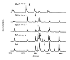
本発明は、VCSELの径方向依存性波長放出パターン、および光がファイバに結合される様式に起因して、ファイバ結合モードが、ファイバ半径に依存するスペクトル成分を有し、無視できない色または材料分散効果をもたらすという発見を利用する。図1は、ファイバコアにわたる5つの径方向オフセットに対するMMFにおいて伝搬するモードの光スペクトルを示す。各径方向スペクトルに対する中心波長、または中央波長は、下矢印により示されている。図1に示されるように、この特定の光伝送機において、平均的に、ファイバモードの中央波長は、より大きな径方向オフセットに対してより短波長側にシフトする。この径方向波長依存性は、ファイバモードを、モード分散に加えて、互いに対し色または材料分散させる。その結果、屈折率プロファイルは、この材料分散効果を補償し、それによりファイバおよび伝送機の組合せにより実現される全分散を最小化するように修正されなければならない。 Due to the radially dependent wavelength emission pattern of VCSELs and the manner in which light is coupled into the fiber, the fiber coupling mode has a spectral component that depends on the fiber radius, and a non-negligible color or material dispersion Take advantage of discoveries that are effective. FIG. 1 shows the optical spectrum of the mode propagating in the MMF for five radial offsets across the fiber core. The center wavelength, or center wavelength, for each radial spectrum is indicated by the down arrow. As shown in FIG. 1, in this particular optical transmitter, on average, the center wavelength of the fiber mode is shifted to the shorter wavelength side for a larger radial offset. This radial wavelength dependence causes the fiber modes to be color or material dispersed with respect to each other in addition to mode dispersion. As a result, the refractive index profile must be modified to compensate for this material dispersion effect, thereby minimizing the total dispersion achieved by the fiber and transmitter combination.
また、本発明は、高次VCSELモードが、図17に示されるように、材料分散およびモード分散の効果を考慮するために、製造プロセス中により正確なTOSAコンポーネントおよびTOSAコンポーネントのより正確な整列を必要とすることにより、高次ファイバモードに結合される場合があるという発見も利用する。 The present invention also allows higher order VCSEL modes to more accurately align TOSA components and TOSA components more accurately during the manufacturing process to account for the effects of material dispersion and mode dispersion as shown in FIG. It also takes advantage of the discovery that it may be coupled to higher order fiber modes by need.
一態様において、本発明は、ファイバモードの波長における径方向依存性シフトによりもたらされるモードおよび材料分散効果を補償するレーザ最適化多モードファイバの新たなDMD仕様を説明する。必要とされる補償は、VCSELの空間スペクトル特性、VCSELモードのファイバモードへの結合、およびファイバのモード分散特性に依存する。波長における径方向シフトを補償するように設計されたMMFは、低減された全分散および改善されたシステム性能を示す。現在のDMDおよび有効モード帯域幅(EMB)試験法は、ファイバモードの径方向波長依存性を無視しているため、伝送システムにおいて実現されるモード分散または帯域幅性能を正確に特性決定しない。新たなDMD仕様を検証するために、我々は、特許文献1に開示されるように、DMDおよび帯域幅を計算するための改善されたアルゴリズムを適用して、様々な量の材料分散補償のためにVCSELのサンプルの組に対するDMDおよびEMBを計算した。 In one aspect, the present invention describes a new DMD specification for laser optimized multimode fiber that compensates for mode and material dispersion effects caused by radial dependent shifts in the wavelength of the fiber mode. The required compensation depends on the spatial spectral characteristics of the VCSEL, the coupling of the VCSEL mode to the fiber mode, and the mode dispersion characteristics of the fiber. An MMF designed to compensate for radial shifts in wavelength exhibits reduced total dispersion and improved system performance. Current DMD and effective mode bandwidth (EMB) test methods do not accurately characterize the modal dispersion or bandwidth performance achieved in a transmission system because they ignore the radial wavelength dependence of the fiber mode. In order to verify the new DMD specification, we apply an improved algorithm for calculating DMD and bandwidth as disclosed in US Pat. The DMD and EMB for a set of VCSEL samples were calculated.
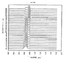
レーザ最適化MMFの帯域幅を特性決定するために使用される試験法は、TIA−455−220−A標準に指定されるDMDである。DMDは、MMFを横断する最も速いモードと最も遅いモードとの間の伝搬遅延の差のps/m単位で表現される尺度であり、一方で、色分散の効果は最小化される。モード間の相対遅延が大きいほど、分散(すなわち、モード分散)が大きい。DMDを測定するために、単一モード励振ファイバの端部から放出された光基準パルスが、試験下のMMFのコアにわたりステップ化される。各径方向オフセットに対して、結果的な出力パルスの伝搬遅延は、図2に示されるようにサンプリングオシロスコープにより記録される。 The test method used to characterize the bandwidth of laser optimized MMF is DMD as specified in the TIA-455-220-A standard. DMD is a measure expressed in ps / m of the difference in propagation delay between the fastest and slowest modes across the MMF, while the effect of chromatic dispersion is minimized. The greater the relative delay between modes, the greater the variance (ie, mode variance). To measure DMD, an optical reference pulse emitted from the end of a single mode excitation fiber is stepped across the core of the MMF under test. For each radial offset, the resulting output pulse propagation delay is recorded by a sampling oscilloscope as shown in FIG.
出力波形は、所与の径方向オフセットに対する励振パルスにより励起されるそれらのモードのみを含有する。この測定において、励起パルスのスペクトル特性は、一定のままである。DMDを演算するために、径方向オフセット(0μmから24μm)のそれぞれに対する出力波形の組がまず記録される。波形のプロットを図3に示す。プロットは、コア中心から測定される、励振パルスの径方向オフセット(y軸)の関数としてのファイバの出力端部におけるピコ秒毎メートル(ps/m)での相対パルス遅延、または「相対時間」(x軸)を示す。DMDは、最も速いパルスの前縁と最も遅いパルスの後縁との間のパルス遅延の差を測定することにより判定される。この差から、励振パルスの時間幅を差し引くと、ファイバのモード分散が得られる。ファイバをOM3またはOM4と指定するために、DMDは、コアのいくつかの径方向領域内の最小分散値を満たさなければならない。 The output waveform contains only those modes that are excited by excitation pulses for a given radial offset. In this measurement, the spectral characteristics of the excitation pulse remain constant. To compute the DMD, a set of output waveforms for each radial offset (0 μm to 24 μm) is first recorded. A waveform plot is shown in FIG. The plot is the relative pulse delay in picoseconds per meter (ps / m) at the output end of the fiber as a function of the radial offset (y-axis) of the excitation pulse, measured from the core center, or “relative time”. (X-axis) is shown. DMD is determined by measuring the difference in pulse delay between the leading edge of the fastest pulse and the trailing edge of the slowest pulse. By subtracting the time width of the excitation pulse from this difference, the mode dispersion of the fiber is obtained. In order to designate a fiber as OM3 or OM4, the DMD must meet minimum dispersion values in several radial regions of the core.
現在、一般的に、モード分散を最小化するDMD波形プロットは、図4Aに示されるように、全ての径方向オフセット波形が同時にファイバの出力に到達する場合であると考えられている。これは、径方向ファイバモード(出力波形)のそれぞれが、同じスペクトル特性を有する励振パルスにより励起された場合に成り立つ。しかしながら、より大きな励振角度に放出されたより高次のVCSELモードは、平均的に、より小さい励振角度に放出されたそれらのモードよりも短い波長を有するため(図5を参照されたい)、その仮定は有効ではない。VCSELモードがファイバに結合される場合、低次モードおよび高次モードは、モード分散に加えて異なる量の材料分散を示す。材料分散は、材料の屈折率が波長と共に変化する、すなわち以下であるために生じる。すなわち、 Currently, it is generally considered that the DMD waveform plot that minimizes modal dispersion is when all the radial offset waveforms reach the fiber output simultaneously, as shown in FIG. 4A. This is true when each radial fiber mode (output waveform) is excited by an excitation pulse having the same spectral characteristics. However, the assumption is that higher order VCSEL modes emitted at larger excitation angles have on average shorter wavelengths than those emitted at smaller excitation angles (see FIG. 5). Is not valid. When the VCSEL mode is coupled to the fiber, the lower and higher order modes exhibit different amounts of material dispersion in addition to mode dispersion. Material dispersion occurs because the refractive index of the material varies with wavelength, ie: That is,
特許文献1に開示されるアルゴリズムを使用して、我々は、理想的なDMD波形を有する模擬的ファイバに対して、ビット誤り率(BER)試験システムにおいて使用された伝送機のDMDを計算した。このVCSELのファイバのコアにわたる中心波長の差は、0.72nmである。新たなアルゴリズムを適用すると、より大きな径方向オフセットでの計算されたDMD波形(図4B)が、材料分散により右にシフトする(すなわち、遅延がより長い)ことが分かる。したがって、全ての波形が時間的に整列したDMDをもたらす従来の「理想的な」放物線状屈折率プロファイルは、このVCSELに対しては最適ではない。全分散を最小化する(またはシステム帯域幅を最大化する)ために、MMFのコア屈折率プロファイルは、ファイバモードの相対的材料分散(または色分散)を補償するように修正されなければならない。レーザのスペクトル特性を考慮して、必要とされる補償は、特許文献1に開示されるアルゴリズムを使用して計算することができる。特許文献1に開示されるアルゴリズムは、MMFチャネルリンクのシステム性能のより正確な特性決定を提供する。 Using the algorithm disclosed in U.S. Patent No. 6,057,836, we calculated the DMD of the transmitter used in the bit error rate (BER) test system for a simulated fiber with an ideal DMD waveform. The difference in center wavelength across the core of this VCSEL fiber is 0.72 nm. Applying the new algorithm, it can be seen that the calculated DMD waveform with a larger radial offset (FIG. 4B) shifts to the right due to material dispersion (ie, the delay is longer). Thus, the traditional “ideal” parabolic index profile that results in DMD with all waveforms aligned in time is not optimal for this VCSEL. In order to minimize the total dispersion (or maximize the system bandwidth), the core refractive index profile of the MMF must be modified to compensate for the relative material dispersion (or chromatic dispersion) of the fiber mode. Considering the spectral characteristics of the laser, the required compensation can be calculated using the algorithm disclosed in US Pat. The algorithm disclosed in U.S. Pat. No. 6,057,086 provides more accurate characterization of system performance of MMF channel links.
一般に、高速データ通信ネットワークにおいて使用されるVCSEL送受信機は、ファイバに結合されると、サポートされた導波モードにおける波長依存性を生成する空間依存性波長放出パターンを示す。ファイバ結合スペクトルの径方向依存性を定量するための他のパラメータを使用してもよいが、我々は、新たなパラメータΔλcを、MMFのコアにわたる径方向スペクトルの間の中心波長における最大差として定義する。10Gbpsイーサネット(10GBASE−SR)用光送受信機および8Gb/sファイバチャネルの代表的な組に対するΔλcの統計的分布に基づき、レーザ最適化MMFの設計および製造のための新たなDMD仕様が提案される。新たなDMD仕様は、光チャネルの波長における径方向依存性シフトを補償する。例として、図5において、サンプル10Gb/s送受信機に対するΔλcが示されるが、ここで、Δλc=0.53nmである。結合された光出力がファイバコアの狭い領域に限定される場合、補償は、低減された径方向領域に対するΔλcに基づいて調節されなければならないことが留意される。
In general, VCSEL transceivers used in high-speed data communication networks exhibit a spatially dependent wavelength emission pattern that, when coupled to a fiber, creates a wavelength dependency in the supported guided mode. Although other parameters for quantifying the radial dependence of the fiber coupling spectrum may be used, we will use the new parameter Δλ c as the maximum difference in the central wavelength between the radial spectra across the core of the MMF. Define. Based on the statistical distribution of Δλ c for a typical set of 10 Gbps Ethernet (10 GBASE-SR) optical transceiver and 8 Gb / s Fiber Channel, a new DMD specification for laser optimized MMF design and manufacturing was proposed The The new DMD specification compensates for radial dependent shifts in the wavelength of the optical channel. As an example, FIG. 5 shows Δλ c for a
屈折率プロファイルを修正することにより、波長の分布に基づき材料分散の効果を補償するために導波モードの速度を調節することができる。その結果、低減された全分散を有する改善されたMMFを実現することができる。屈折率プロファイルに対する修正は、ファイバにおけるモード伝搬遅延を特徴付けるDMD波形データを使用して定量化することができる。 By modifying the refractive index profile, the speed of the guided mode can be adjusted to compensate for the effects of material dispersion based on the wavelength distribution. As a result, an improved MMF with reduced total dispersion can be realized. Modifications to the refractive index profile can be quantified using DMD waveform data that characterizes mode propagation delay in the fiber.
導波モードの波長依存性飛行時間を測定することにより、MMFにおける材料分散を定量化することができる。本明細書において使用される1つの方法は、DMD測定試験ベッドにおいて使用されるチタン−サファイアレーザの波長を調整することである。明らかに、調整可能および固定波長レーザを含む他のレーザデバイスを使用することができる。ファイバコアにわたる屈折率の最大差は小さいため(<1%)、一般に、1つの径方向オフセットに対応するファイバ結合モードに対する波長依存性飛行時間を特性決定することのみが必要である。 By measuring the wavelength-dependent time-of-flight of the guided mode, the material dispersion in the MMF can be quantified. One method used herein is to tune the wavelength of the titanium-sapphire laser used in the DMD measurement test bed. Obviously, other laser devices including tunable and fixed wavelength lasers can be used. Since the maximum difference in refractive index across the fiber core is small (<1%), it is generally only necessary to characterize the wavelength dependent time of flight for the fiber coupling mode corresponding to one radial offset.
図6を参照すると、550m長のMMFを通って伝搬する2つの径方向励振オフセット、5μmおよび19μmに対して飛行時間がプロットされている。図6中の2つの曲線のそれぞれは、ファイバの材料分散n(λ)を定量化する。より長い波長は、より短い遅延時間を有し、したがってより速く移動する。曲線における垂直シフトは、2つの径方向モード間のモード伝搬遅延、またはモード分散の差に起因するものであり、物質分散に関連しない。データは、2つの曲線の傾きがほぼ同じであることを示している。図6に示される絶対飛行時間を、ピコ秒毎メートル(ps/m)での相対遅延に変換することにより、材料およびモード分散の効果を関連付けることができ、モード分散に起因する遅延は、DMD波形データから得られる。 Referring to FIG. 6, the time of flight is plotted against two radial excitation offsets, 5 μm and 19 μm, propagating through a 550 m long MMF. Each of the two curves in FIG. 6 quantifies the material dispersion n (λ) of the fiber. Longer wavelengths have shorter delay times and therefore move faster. The vertical shift in the curve is due to the difference in mode propagation delay or mode dispersion between the two radial modes and is not related to material dispersion. The data shows that the slopes of the two curves are almost the same. By converting the absolute time of flight shown in FIG. 6 into relative delay in picoseconds per meter (ps / m), the effects of material and modal dispersion can be related, and the delay due to modal dispersion is DMD Obtained from waveform data.
図7を参照すると、5μmオフセットに対する材料分散に起因する遅延がプロットされている。19μmに対するデータ点は、ほぼ同一であるため、図7には示されていない。 Referring to FIG. 7, the delay due to material dispersion for a 5 μm offset is plotted. Data points for 19 μm are not shown in FIG. 7 because they are nearly identical.
図6および7における飛行時間は、現在のDMDおよびEMBメトリクスにより予測されるものより大幅に高いシステム性能を示す試験ファイバに対するものである。図3を参照すると、ファイバのDMDデータの分析は、19μmオフセットでの高次モードが、5μmオフセットでの低次モードよりも、モード分散である約0.066ps/mだけ速くファイバを横断することを示している。VCSEL伝送機により励起される場合、これらの2つの径方向オフセット(5μmおよび19μmオフセット)に対するモードは、中心波長において異なる。使用されるVCSELにより励起される場合、ファイバモードのスペクトル分析は、19μmオフセットでのモードが、約848.1nmの中央波長を有し、一方5μmオフセットでのモードが、848.8nmの中央波長を有することを明らかにしている。図7に示される飛行時間(TOF)曲線から、この中央波長の差は、0.070ps/mの相対時間遅延の差に対応することが分かる。しかしながら、19μmでの高次モードの光スペクトルは、より短い中心波長を有することから、平均的にモードはより遅く移動する。したがって、負の材料分散(−0.070ps/m)は、正のモード分散(+0.066ps/m)を補償し、全システム分散を0.004ps/mに低減する。ゆえに、ファイバはほとんど分散を導入せず、従来のDMDおよびEMB測定法により予測されるよりも良好に機能する。DMD波形径方向遅延におけるこの非対称性は、現在の標準試験法においては考慮されていない。 The time of flight in FIGS. 6 and 7 is for a test fiber that exhibits significantly higher system performance than that predicted by current DMD and EMB metrics. Referring to FIG. 3, analysis of fiber DMD data shows that the higher order mode at 19 μm offset traverses the fiber faster than the lower order mode at 5 μm offset by approximately 0.066 ps / m, which is the mode dispersion. Is shown. When excited by a VCSEL transmitter, the modes for these two radial offsets (5 μm and 19 μm offset) are different at the center wavelength. When excited by the VCSEL used, spectral analysis of the fiber mode shows that the mode at 19 μm offset has a central wavelength of about 848.1 nm, while the mode at 5 μm offset has a central wavelength of 848.8 nm. It is made clear to have. From the time-of-flight (TOF) curve shown in FIG. 7, it can be seen that this central wavelength difference corresponds to a relative time delay difference of 0.070 ps / m. However, the higher order mode light spectrum at 19 μm has a shorter center wavelength, so on average the mode moves slower. Thus, negative material dispersion (−0.070 ps / m) compensates for positive mode dispersion (+0.066 ps / m) and reduces total system dispersion to 0.004 ps / m. Thus, the fiber introduces little dispersion and performs better than expected by conventional DMD and EMB measurements. This asymmetry in DMD waveform radial delay is not considered in current standard test methods.
所与のレーザ光源またはTOSAおよび結合ファイバモードの中央波長における径方向の変動に対して、ファイバモードが材料分散に起因して受ける相対遅延を計算することができる。次いで、材料分散を補償するために、モードが平均的により速く、またはより遅く移動するように、ファイバの屈折率を修正することができる。より短い波長をより大きい角度に放出する放出パターン(例えば、VCSEL)に対して、ファイバに結合されると、高次ファイバモードは、低次モードよりも比較的遅く移動する。この場合、屈折率は、高次モードがより速く移動するように、より大きい径方向オフセットで低減されなければならない。目的は、最終的な全分散が最小化されるように、導波ファイバモードの相対遅延を、モードが受けることになる波長依存性材料分散と平衡化することである。材料分散を補償するために必要な相対遅延を知れば、屈折率プロファイルに対する必要な調節を行うことができる。屈折率における必要な変化は、以下のモード位相速度との関係により計算することができる。 For a given laser source or TOSA and the radial variation at the center wavelength of the coupled fiber mode, the relative delay that the fiber mode experiences due to material dispersion can be calculated. The refractive index of the fiber can then be modified so that the mode moves on average faster or slower to compensate for material dispersion. For an emission pattern that emits shorter wavelengths at larger angles (eg, VCSELs), when coupled to a fiber, higher order fiber modes move relatively slower than lower order modes. In this case, the refractive index must be reduced with a larger radial offset so that higher order modes move faster. The objective is to balance the relative delay of the waveguide fiber mode with the wavelength dependent material dispersion that the mode will experience, so that the final total dispersion is minimized. Knowing the relative delay required to compensate for material dispersion, the necessary adjustments to the refractive index profile can be made. The required change in refractive index can be calculated by the relationship with the following mode phase velocity.
式中、cは、光の速度(299,792,458m/s)であり、vは、モード位相速度(m/s)である。 Where c is the speed of light (299, 792, 458 m / s) and v is the mode phase speed (m / s).
各送受信機は、一意の空間スペクトル分布を示すため、径方向スペクトル中央波長の差(Δλc)は、材料または色分散の効果を最小限化する名目上の送受信機に対して推定されなければならない。VCSELの波長依存性空間放出パターンのMMFへの結合を正確に理解すれば、改善された設計パラメータが得られる。異なるクラスのVCSEL送受信機(例えば、ファイバチャネルに使用されるもの、およびイーサネットに使用されるもの)が異なる径方向依存性波長放出パターンを示す場合、各アプリケーションに対して最適ファイバ設計パラメータを判定することができる。特定用途向けの性能のためのファイバ(「調整された」MMF)を分類することが実用的である場合がある。 Since each transceiver exhibits a unique spatial spectral distribution, the radial spectral center wavelength difference (Δλ c ) must be estimated for a nominal transceiver that minimizes the effects of material or chromatic dispersion. Don't be. An accurate understanding of the coupling of the VCSEL's wavelength-dependent spatial emission pattern to the MMF provides improved design parameters. If different classes of VCSEL transceivers (eg those used for Fiber Channel and those used for Ethernet) exhibit different radial dependent wavelength emission patterns, determine the optimal fiber design parameters for each application be able to. It may be practical to classify fibers for application specific performance ("tuned" MMF).
例として、材料分散の効果は、0.53nmのΔλcを有する無作為に選択されたVCSELに対して補償されている。このVCSELに対して、屈折率プロファイルは、DMD波形ピークが、0μmから24μmで約−0.04ps/mの遅延の全体的な相対シフトを示すように調節されるべきであり、より大きな半径に対してはより短い遅延となる。補償は、Δλc、およびモードが励起されるコアの径方向領域の両方に依存する。修正された屈折率プロファイルの一実施形態は、図8Aに示されるように、ファイバのコアにわたる遅延における単調なシフトに対して設計することである。図8Aに示されるシフトは、0μmから24μmで0.09ps/mの遅延をもたらす(「左に傾いた」シフト)。しかしながら、レーザ光源波長放出パターンおよびファイバ結合特性に依存して、他の径方向シフトがより適切となる場合がある。計算されたDMD波形(特許文献1に開示される時間領域アルゴリズムを使用)を、図8Bに示す。計算された波形を厳密に検査すると、相対遅延がほぼ整列し、低い全分散をもたらすことが示される。 As an example, the effect of material dispersion is compensated for a randomly selected VCSEL having a Δλ c of 0.53 nm. For this VCSEL, the refractive index profile should be adjusted so that the DMD waveform peak shows an overall relative shift in delay of about −0.04 ps / m from 0 μm to 24 μm, with a larger radius. For this, the delay is shorter. Compensation depends on both Δλ c and the radial region of the core where the mode is excited. One embodiment of a modified index profile is to design for a monotonic shift in delay across the fiber core, as shown in FIG. 8A. The shift shown in FIG. 8A results in a 0.09 ps / m delay from 0 μm to 24 μm (a “tilt left” shift). However, other radial shifts may be more appropriate depending on the laser source wavelength emission pattern and fiber coupling characteristics. The calculated DMD waveform (using the time domain algorithm disclosed in Patent Document 1) is shown in FIG. 8B. Close examination of the calculated waveform shows that the relative delays are approximately aligned, resulting in low total dispersion.
新たなDMD仕様を検証するために、DMD波形が図9Aおよび9Bに示される2つのサンプルファイバに対して、新たなアルゴリズムを適用した。現在の試験法に基づき、これらの2つのファイバに対する測定されたDMDおよびEMBは、事実上同一である(EMBは約4543MHz*km)が、その測定されたビット誤り率(BER)システム性能は、2桁超異なり、ファイバ(a)がより高いシステム性能を示す。これらの2つのファイバに対するDMDは同じであるが、それらの径方向波形ピークは、より大きい半径において、反対方向にシフト(遅延)する(「左」対「右」シフトファイバ)ことが留意される。 To validate the new DMD specification, a new algorithm was applied to the two sample fibers whose DMD waveforms are shown in FIGS. 9A and 9B. Based on current test methods, the measured DMD and EMB for these two fibers are virtually identical (EMB is approximately 4543 MHz * km), but its measured bit error rate (BER) system performance is Over two orders of magnitude, fiber (a) shows higher system performance. It is noted that the DMD for these two fibers is the same, but their radial waveform peaks are shifted (delayed) in the opposite direction at a larger radius (“left” vs. “right” shifted fiber). .
アルゴリズムを使用して、我々のBER試験システムVCSELのスペクトル特性に関するこれら2つのファイバの計算DMD波形を、図10Aおよび10Bに示す。図10AにおけるDMD波形は、図9AにおけるDMD波形よりも整列している。一方、図10BにおけるDMD波形は、図9BにおけるDMD波形よりも右側に(より大きな半径で)よりシフトしている。これらの2つのファイバに対する最小計算帯域幅(minEMBc)は、3524MHz*kmおよび2913MHz*kmであり、帯域幅における20%の差を予測している。ファイバの特定の帯域幅(EMB)は、1.13倍だけ計算最小EMB(minEMBc)に関連しており、すなわち、EMB=1.13×minEMBcである。この計算帯域幅における差はまた、新たに計算されたDMDにおいても観察される。したがって、特許文献1に開示されるアルゴリズムは、これらの2つのファイバ間のシステム性能における観察される差を正確に予測する。 Using an algorithm, the calculated DMD waveforms of these two fibers with respect to the spectral characteristics of our BER test system VCSEL are shown in FIGS. 10A and 10B. The DMD waveform in FIG. 10A is more aligned than the DMD waveform in FIG. 9A. On the other hand, the DMD waveform in FIG. 10B is more shifted to the right (with a larger radius) than the DMD waveform in FIG. 9B. The minimum calculated bandwidth (minEMBc) for these two fibers is 3524 MHz * km and 2913 MHz * km, predicting a 20% difference in bandwidth. The specific bandwidth (EMB) of the fiber is related to the calculated minimum EMB (minEMBc) by 1.13 times, ie EMB = 1.13 × minEMBc. This difference in computational bandwidth is also observed in the newly calculated DMD. Thus, the algorithm disclosed in US Pat. No. 6,057,059 accurately predicts the observed difference in system performance between these two fibers.
ケーブル内の全てのファイバにアルゴリズムを適用して、図11A、11B、11C、および11Dに示されるように、BERシステム性能を有する標準的および予測minEMBcおよびDMD(Inner Mask仕様)メトリクスを比較することができる。図11Bおよび11Dの予測メトリクスは、測定されたシステム性能(R2=0.58対R2=0.93)およびDMD(R2=0.76対R2=0.96)へのはるかに改善された相関を示す。 Apply the algorithm to all fibers in the cable to compare standard and predicted minEMBc and DMD (Inner Mask specifications) metrics with BER system performance, as shown in FIGS. 11A, 11B, 11C, and 11D Can do. The predictive metrics of FIGS. 11B and 11D are much more to the measured system performance (R 2 = 0.58 vs R 2 = 0.93) and DMD (R 2 = 0.76 vs R 2 = 0.96). Shows improved correlation.
図11Aは、本発明の一実施形態による、標準試験法を用いて測定されたminEMBcのグラフを示す。図11Bは、本発明の一実施形態による、新たに計算され畳み込まれたminEMBcのグラフを示す。図11Cは、本発明の一実施形態による、標準試験法を用いて測定されたDMD、Inner Mask仕様のグラフを示す。図11Dは、本発明の一実施形態による、新たに計算され畳み込まれたDMD、Inner Mask仕様のグラフを示す。 FIG. 11A shows a graph of minEMBc measured using a standard test method, according to one embodiment of the invention. FIG. 11B shows a newly computed and convolved minEMBc graph according to one embodiment of the invention. FIG. 11C shows a graph of DMD, Inner Mask specifications measured using standard test methods, according to one embodiment of the present invention. FIG. 11D shows a newly computed and convolved DMD, Inner Mask specification graph, according to one embodiment of the invention.
特許文献1に開示される新たなアルゴリズムは、平均的VCSELおよび結合ファイバモードにおける径方向波長分布を補償するために必要とされるDMDにおけるシフトを特性決定することにより、MMFファイバの設計仕様に拡張することができる。補償は、ファイバのコアにわたる、0μmから24μmオフセットのDMD波形ピークにおける単調なシフトとして定義される。Δλcの効果を補償するために必要なシフトを判定するために、異なる量の線形DMDシフトを有する模擬ファイバの組に対して、minEMBcが計算される(0μmから24μmの0.09ps/mのシフトに関して図8Aに示されるように)。図12を参照すると、計算されたminEMBc(図8においてサンプリング範囲をカバーするように選択された3つの代表的送受信機に対して)は、様々な程度のDMD補償に対してプロットされている。「畳み込みなし」と標示された曲線は、補償の量(DMD波形におけるシフト)の増加に伴うminEMBcの減少を示す。標準的アルゴリズムは、全ての波形が並列した場合にminEMBcのより高い値を予測する(「畳み込みなし」の曲線に対してはDMD補償なし)。 The new algorithm disclosed in U.S. Pat. No. 6,057,075 extends to MMF fiber design specifications by characterizing the shift in DMD required to compensate for radial wavelength distribution in average VCSEL and coupled fiber modes. can do. Compensation is defined as a monotonic shift in the DMD waveform peak of 0 μm to 24 μm offset across the core of the fiber. In order to determine the shift required to compensate for the effect of Δλ c , minEMBc is calculated (0.09 ps / m from 0 μm to 24 μm) for a set of simulated fibers with different amounts of linear DMD shift. As shown in FIG. 8A for shift). Referring to FIG. 12, the calculated minEMBc (for the three representative transceivers selected to cover the sampling range in FIG. 8) is plotted for various degrees of DMD compensation. The curve labeled “no convolution” shows a decrease in minEMBc with increasing amount of compensation (shift in DMD waveform). The standard algorithm predicts a higher value of minEMBc when all waveforms are in parallel (no DMD compensation for “no convolution” curve).
図13を参照すると、図12中の曲線のそれぞれに対して最大の新たに計算されたminEMBcを抽出することにより、所与の送受信機に対する最適DMD補償(Δλc)を判定することができる。 Referring to FIG. 13, the optimum DMD compensation (Δλ c ) for a given transceiver can be determined by extracting the largest newly calculated minEMBc for each of the curves in FIG.
我々の10GBASE−SR適合送受信機のサンプルの組(18のデバイス)に基づき、我々は、0.4nmの平均Δλcを補償すべきである。図13を使用して、0〜24μmの必要な補償は、10Gbpsイーサネットに対して−0.04ps/mである。 Based on our 10GBASE-SR compliant transceiver sample set (18 devices), we should compensate for an average Δλ c of 0.4 nm. Using FIG. 13, the required compensation of 0-24 μm is −0.04 ps / m for 10 Gbps Ethernet.
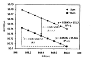
上述のサンプルファイバに対するDMD補償は、この予測最適補償値−0.04ps/m(0〜24μm)に近い。このファイバに対する3dB帯域幅は、5つの異なるVCSEL送受信機を使用して測定された。VCSELのそれぞれの光スペクトルは、ファイバのコアにわたり測定された。5つの異なるVCSEL送受信機を使用して測定された帯域幅とサンプルファイバのΔλcとの間の相関は、図14にプロットされる。データは、このファイバの最大計算帯域幅が、0.4nmのΔλcに対して得られることを実証している。 The DMD compensation for the sample fiber described above is close to this predicted optimal compensation value of −0.04 ps / m (0 to 24 μm). The 3 dB bandwidth for this fiber was measured using 5 different VCSEL transceivers. The optical spectrum of each VCSEL was measured across the fiber core. The correlation between the bandwidth measured using five different VCSEL transceivers and the Δλ c of the sample fiber is plotted in FIG. The data demonstrates that the maximum calculated bandwidth of this fiber is obtained for Δλ c of 0.4 nm.
本明細書において開示される新たなDMD仕様は、現在の「理想的」DMD設計メトリクスに置き換わるべきである。実際には、典型的DMD波形プロットは、製造プロセスにおける変動の結果、複数の径方向遅延シフトおよびモード分裂を示すことが認識される。これは、本明細書において提案されるように、新たな目標屈折率プロファイルに対する基本設計要件を損なうことがない。我々が名目上の送受信機を設計することを仮定して、改善されたMMFシステム性能の基礎的要件は、結果的なDMD波形プロットがより大きな径方向オフセットにおいてより低い伝搬遅延への相対シフトを見せるように(「左」シフト)、屈折率プロファイルがバイアスされることである。1つの許容されるメトリクスは、19μmと5μm径方向オフセットとの間の遅延の差が負の数であることを保証することである。明らかに、他の径方向オフセットを使用することができるが、我々は、これらの値が、測定されるシステム性能に最善の相関を提供することを見出した。 The new DMD specification disclosed herein should replace the current “ideal” DMD design metrics. In practice, it is recognized that typical DMD waveform plots show multiple radial delay shifts and mode splits as a result of variations in the manufacturing process. This does not detract from the basic design requirements for the new target refractive index profile, as proposed herein. Assuming that we design a nominal transceiver, the fundamental requirement for improved MMF system performance is that the resulting DMD waveform plot shows a relative shift to lower propagation delay at larger radial offsets. As shown ("left" shift), the refractive index profile is biased. One acceptable metric is to ensure that the delay difference between 19 μm and 5 μm radial offset is a negative number. Obviously, other radial offsets can be used, but we have found that these values provide the best correlation to the measured system performance.
改善されたチャネルリンク性能のためには、レーザ最適化MMFの屈折率プロファイルが、VCSEL送受信機により励起された場合のファイバモードの中心波長における径方向依存性変動を補償するように修正されてもよいことが提案される。10GBASE−SR適合VCSEL送受信機に対しては、屈折率プロファイルは、DMD波形ピークが、増加する径方向オフセットに対してより短い遅延への単調なシフトを示すように修正されるべきである。DMD波形ピークにおける提案されるシフトは、0μmから24μmの範囲にわたり−0.04ps/mである。この値は、平均的VCSEL伝送機および結合ファイバモードの波長分布を補償する。 For improved channel link performance, the refractive index profile of the laser optimized MMF may be modified to compensate for radial dependent variations in the center wavelength of the fiber mode when pumped by a VCSEL transceiver. Good things are suggested. For a 10GBASE-SR compliant VCSEL transceiver, the refractive index profile should be modified so that the DMD waveform peak shows a monotonic shift to shorter delay for increasing radial offset. The proposed shift in the DMD waveform peak is -0.04 ps / m over a range of 0 μm to 24 μm. This value compensates for the wavelength distribution of the average VCSEL transmitter and the coupled fiber mode.
異なる径方向依存性放出パターンを示すVCSEL送受信機または他の源に対して、波長の径方向変動を補正するために異なる補償が必要となることが理解される。ファイバ結合モードが逆の径方向依存性波長分布(すなわち、高次モードに結合されるより長い波長)を示す場合、DMD補償は、負ではなく正であるべきである。一般に、いかなる径方向依存性波長分布も、低減された全分散のために補償することができる。 It will be appreciated that for VCSEL transceivers or other sources that exhibit different radial dependent emission patterns, different compensation is required to correct for wavelength radial variations. If the fiber coupling mode exhibits an opposite radial dependent wavelength distribution (ie longer wavelengths coupled to higher order modes), the DMD compensation should be positive rather than negative. In general, any radial dependent wavelength distribution can be compensated for the reduced total dispersion.
製造プロセスにおける変動に起因して、本明細書において指定されるようなレーザ最適化MMFに対する(10Gb/sイーサネットまたは高速ファイバチャネルに対する)分散補償は、OM4タイプMMFに対しては0ps/mと0.−0.14ps/mとの間、OM3タイプファイバに対しては0ps/mと−0.33ps/mとの間の左シフトメトリクスのDMD波形プロファイル要件を満たすべきであり、すなわち、 Due to variations in the manufacturing process, dispersion compensation (for 10 Gb / s Ethernet or high speed fiber channel) for laser optimized MMF as specified herein is 0 ps / m and 0 for OM4 type MMF. . Should meet DMD waveform profile requirements for left shift metrics between -0.14 ps / m and for OM3 type fiber between 0 ps / m and -0.33 ps / m, ie
OM4に対しては−0.14ps/m<(19μmにおける遅延−5μmにおける遅延)<0.0ps/mおよび−0.33ps/m<(19μmにおける遅延−5μmにおける遅延)<0.0ps/mとなるべきである。このようにして、このDMD波形プロファイル要件を使用して、MMFは、材料分散およびモード分散を補償するMMFを製造することができる。 For OM4, −0.14 ps / m <(delay at 19 μm−delay at 5 μm) <0.0 ps / m and −0.33 ps / m <(delay at 19 μm−delay at 5 μm) <0.0 ps / m Should be. In this way, using this DMD waveform profile requirement, the MMF can produce an MMF that compensates for material dispersion and mode dispersion.
10GBASE−SRおよび2G/4G/8Gファイバチャネル送受信機の代表的なサンプル母集団に基づき、伝送機およびファイバシステムの全分散が、−0.01ps/mから−0.04ps/mの間のOM4タイプファイバのDMD遅延シフトに対して最小化することができることが、経験的に判定された。 Based on a representative sample population of 10GBASE-SR and 2G / 4G / 8G Fiber Channel transceivers, the total dispersion of the transmitter and fiber system is between OM4 and -0.04ps / m. It has been determined empirically that it can be minimized for DMD delay shifts of type fibers.
一態様において、本発明は、材料分散およびモード分散効果を補償する、一連のファイバ結合光出力および特定のファイバ結合空間スペクトル分布の両方を生成する伝送機光サブアセンブリ(TOSA)を備える光送受信機を提供する。 In one aspect, the present invention provides an optical transceiver comprising a transmitter optical subassembly (TOSA) that generates both a series of fiber coupled light outputs and a specific fiber coupled spatial spectral distribution that compensates for material dispersion and mode dispersion effects. I will provide a.
ファイバコアにわたりかなりの傾斜を有する任意のファイバ結合空間スペクトル分布は、適切に設計されたファイバにより補償されてもよい材料分散をもたらす場合があるが、本発明の1つの好ましい実施形態は、図17に示されるように、高次VCSELモードを高次ファイバモードに結合することである。これは、製造プロセス中にTOSA内のより正確なコンポーネントおよびTOSA整列のより正確な制御を必要とすることにより達成することができる。好ましくは、TOSA内のコンポーネントの整列は、1mm以下以内の許容差までであり、TOSA内のコンポーネントは、1mm以下以内の許容差まで製造される。実験データは、この特定の実施形態が、ファイバコアにわたるより大きなスペクトル分布をもたらし、それにより、補償に使用されてもよいより大きな材料分散効果を提供することを示唆している。 Although any fiber coupling spatial spectral distribution with significant slope across the fiber core may result in material dispersion that may be compensated by a properly designed fiber, one preferred embodiment of the present invention is shown in FIG. Is to couple the higher order VCSEL mode to the higher order fiber mode. This can be achieved by requiring more precise components within the TOSA and more precise control of the TOSA alignment during the manufacturing process. Preferably, the alignment of the components in the TOSA is up to a tolerance of 1 mm or less, and the components in the TOSA are manufactured to a tolerance of 1 mm or less. Experimental data suggests that this particular embodiment provides a greater spectral distribution across the fiber core, thereby providing a greater material dispersion effect that may be used for compensation.
材料分散は、モード分散により補償されてもよいことが述べられたが、8GHz・km未満の有効モード帯域幅(EMB)を有する中程度帯域幅レーザ最適化ファイバおよび市販の送受信機に対しては、モード分散の効果は材料分散よりも程度が大きく、したがって、モード分散は材料分散により少なくとも部分的に補償されると言うのが通例となる場合がある。 It has been stated that material dispersion may be compensated by modal dispersion, but for medium bandwidth laser optimized fibers and commercial transceivers with an effective mode bandwidth (EMB) of less than 8 GHz · km. It may be customary to say that the effect of modal dispersion is greater than that of material dispersion, and thus modal dispersion is at least partially compensated by material dispersion.
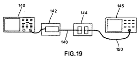
図19、20、および21を参照すると、10Gb/sイーサネットおよび8Gb/sファイバチャネル標準に適合する短波長高ビットレート多モードファイバ送受信機のファイバ結合空間スペクトル分布を定量化する、一連の実験が示されている。これらの実験において、未修正送受信機142に電源が投入され、10Gb/sまたは8Gb/s擬似ランダム2進法シーケンス(PRBS)で変調された。送受信機142の出力は、適切なコネクタ(LC)を有するMMFパッチコード148を送受信機142に嵌合することにより結合した。MMFパッチコード148の遠位端の端面を整列させ、次いで、マイクロポジショニングステージ144を使用して単一モードファイバ(SMF)パッチコード150でスキャンし、光スペクトルアナライザ(OSA)146に結合した。この実験構成により、ファイバ結合スペクトルをMMFパッチコード148のコアにわたり定量化した。
Referring to FIGS. 19, 20, and 21, a series of experiments to quantify the fiber coupled spatial spectral distribution of short wavelength high bit rate multimode fiber transceivers that meet 10 Gb / s Ethernet and 8 Gb / s Fiber Channel standards. It is shown. In these experiments, the
図20は、特定の送受信機に対する、2つの異なるファイバコア半径:r=0μmおよびr=24μmにおける測定されたファイバ結合スペクトルを示す。スペクトル成分は大体同じであるが、その大きさは同じではなく、したがって計算される中央波長λcは異なることに留意されたい。r=0μmにおけるλcは849.7nmであり、一方r=24μmにおけるλcは849.2nmである。 FIG. 20 shows the measured fiber coupling spectra at two different fiber core radii: r = 0 μm and r = 24 μm for a particular transceiver. Note that the spectral components are roughly the same, but their magnitudes are not the same and therefore the calculated center wavelength λ c is different. λ c at r = 0 μm is 849.7 nm, while λ c at r = 24 μm is 849.2 nm.
図21を参照すると、2つの異なる送受信機に対するファイバコアにわたる中央波長の計算された変化Δλc(Δλc=λc・λc minimum)が示されている。ファイバ結合波長変動を特性決定するために、他のメトリクスを使用することもできることが理解される。送受信機Aに対するファイバ結合モードは、送受信機Bに対するファイバコアオフセットに対し減少するλcを示しており、スペクトルはより短い波長のより高い振幅を有している。この情報から、送受信機Aの第1のTOSA内のコンポーネントが正確であり、良好に整列していることが推察される場合がある。逆に、送受信機Bのファイバ結合モードは、ファイバコアオフセットに対し増加するλcを示しており、これは、より低次のVCSELモードがより高次のファイバモードに結合される状況に対応する。さらに、送受信機Bの第2のTOSA内のコンポーネントが不正確であり、かつ/または良好に整列していないことを推察することができる。要約すると、中心波長変動の大きさおよび均一性は、VCSELおよび光サブアセンブリ整列に依存する。このファイバ結合空間スペクトル分布は、屈折率を波長と共に変動させるガラスの固有分散特性と共に、材料分散をもたらす。 Referring to FIG. 21, the calculated change Δλ c (Δλ c = λ c · λ c minimum ) of the center wavelength across the fiber core for two different transceivers is shown. It will be appreciated that other metrics may be used to characterize fiber coupling wavelength variations. The fiber coupling mode for transceiver A shows a decreasing λ c with respect to the fiber core offset for transceiver B, and the spectrum has a higher amplitude of shorter wavelengths. From this information, it may be inferred that the components in the first TOSA of transceiver A are accurate and well aligned. Conversely, the fiber coupling mode of transceiver B shows an increasing λ c with respect to the fiber core offset, which corresponds to the situation where a lower order VCSEL mode is coupled to a higher order fiber mode. . Furthermore, it can be inferred that the components in the second TOSA of the transceiver B are inaccurate and / or not well aligned. In summary, the magnitude and uniformity of the central wavelength variation depends on the VCSEL and optical subassembly alignment. This fiber-coupled spatial spectral distribution results in material dispersion along with the intrinsic dispersion properties of the glass that cause the refractive index to vary with wavelength.
従来のMMFにおいて、850nmの波長領域内で、屈折率は波長の増加と共に減少し、したがってより短波長の放射線は、増加した屈折率に起因して、より長波長の放射線よりも若干遅く移動する。特定のファイバ結合空間スペクトル分布の知識を使用して、材料分散、ならびに、材料分散を完全に補償して無効化し得る特定量(方向および大きさ)のモード分散の両方の効果を判定するために使用されてもよい。したがって、ファイバは、特定のファイバ結合スペクトル分布からもたらされる材料分散を効果的に平衡化する特定量のモード分散を有するように、意図的に設計および製造することができる。特定の送受信機/TOSAからもたらされる材料分散効果は、特別設計ファイバ屈折率プロファイルで十分に補償される場合があるが、ファイバおよび送受信機の組合せを個別に最適化するのは商業的に実用的ではなく、その代わりに、この補償は一体として行われなければならない。 In conventional MMF, within the 850 nm wavelength region, the refractive index decreases with increasing wavelength, so shorter wavelength radiation travels slightly slower than longer wavelength radiation due to the increased refractive index. . Using knowledge of specific fiber coupling spatial spectral distributions to determine the effects of both material dispersion and the specific amount (direction and magnitude) of modal dispersion that can be fully compensated and nullified May be used. Thus, the fiber can be intentionally designed and manufactured to have a specific amount of modal dispersion that effectively balances the material dispersion resulting from the specific fiber coupling spectral distribution. Material dispersion effects resulting from a particular transceiver / TOSA may be well compensated with specially designed fiber refractive index profiles, but it is commercially practical to optimize the fiber and transceiver combination individually Instead, this compensation must be done as a unit.
送受信機ファイバ結合空間スペクトル分布の範囲をより良く理解するために、38の短波長高ビットレート多モードファイバ送受信機に対し、0μmから5μmの内部ファイバコア領域と、19μmから24μmの外部ファイバコア領域との間のファイバ結合中央波長の差を判定した。24個の送受信機は、10Gb/sイーサネットに適合し、14個の送受信機は8Gb/sファイバチャネルに適合していた。これらの送受信機は、米国カリフォルニア州サニーベールのFinisar Corporation、米国カリフォルニア州サンノゼのAvago Technologies、Fiberxon Inc.、および米国カリフォルニア州ミルピタスのJDS Uniphaseを含む、いくつかの供給業者により製造された。このデータのヒストグラムを、図22に示す。Δλcの符号規約は、λcが内部領域内にあるとき、0μmから10μmの、>λcが外部領域内にあるとき、11μmから24μmであり、Δλcは正であるように定義された。図21中の送受信機Aは、Δλc=0.621nmを有し、図21中の送受信機Bは、Δλc=−0.29nmを有していた。 To better understand the range of transceiver fiber coupled spatial spectrum distribution, an internal fiber core region of 0 μm to 5 μm and an external fiber core region of 19 μm to 24 μm for 38 short wavelength high bit rate multimode fiber transceivers. The difference of the fiber coupling center wavelength between and was determined. Twenty-four transceivers were adapted for 10 Gb / s Ethernet, and 14 transceivers were adapted for 8 Gb / s Fiber Channel. These transceivers are available from Finisar Corporation, Sunnyvale, California, USA, Avago Technologies, Fiberxon Inc., San Jose, CA. , And JDS Uniphase of Milpitas, California, USA. A histogram of this data is shown in FIG. [Delta] [lambda] c of the sign convention when the lambda c is within the interior region of 10μm from 0 .mu.m,> lambda when c is outside the region, a 24μm from 11 [mu] m, [Delta] [lambda] c is defined as being positive . The transceiver A in FIG. 21 had Δλ c = 0.621 nm, and the transceiver B in FIG. 21 had Δλ c = −0.29 nm.
残念ながら、図22に示されるように、試験した送受信機の集団に対するファイバコアにわたる計算されたデルタ中央波長における著しい広がりが存在し、したがって、それに対応したファイバのモード分散により補償されなければならない分散の大きな広がりが存在する。その結果、良好に補償されたシステムには、この集団の多様性に対応するように多くのファイバを設計および製造する必要があることになる。さらに、ファイバおよび送受信機は、典型的には、異なる時点で設置されるため、特定のファイバを特定の送受信機に整合させることは実用的ではない。 Unfortunately, as shown in FIG. 22, there is a significant spread in the calculated delta center wavelength across the fiber core for the tested transceiver population, and therefore the dispersion that must be compensated by the corresponding fiber mode dispersion. There is a great spread of. As a result, a well compensated system will require many fibers to be designed and manufactured to accommodate this diversity of populations. In addition, since fibers and transceivers are typically installed at different times, it is not practical to match a particular fiber to a particular transceiver.
代替のより有利でない実施形態は、特定のファイバ結合空間スペクトル分布が最小空間依存性を有するように、VCSELモードを結合することである。この特定の実施形態は、ファイバが最小モード分散を有し、システムが材料分散の効果により制限されることになる場合に、最小限の全分散を実現することになる。しかしながら、良好に補償されたシステムは、モードおよび材料分散効果の両方を効果的に補償することができることにより、全分散の低減を実現することに留意されたい。 An alternative less advantageous embodiment is to combine the VCSEL modes so that a particular fiber coupling spatial spectral distribution has minimal spatial dependence. This particular embodiment will achieve minimal total dispersion when the fiber has minimal mode dispersion and the system will be limited by the effects of material dispersion. However, it should be noted that a well-compensated system achieves a reduction in total dispersion by being able to effectively compensate for both mode and material dispersion effects.
本発明の利点は、モードおよび材料効果を含む全分散が、正確な分散補償を介して最小化することができるという事実によって、より高性能の光リンクを促進することである。あるいは、ファイバ結合空間スペクトル分布における広い変動によって、モードおよび材料分散が、集団全体にわたり性能を最適化するようにファイバを設計することにより部分的にのみ補償することができる。 An advantage of the present invention is that it promotes higher performance optical links due to the fact that total dispersion, including mode and material effects, can be minimized through accurate dispersion compensation. Alternatively, due to the wide variation in the fiber coupling spatial spectral distribution, mode and material dispersion can only be partially compensated by designing the fiber to optimize performance across the population.
図23を参照すると、1)ファイバ結合空間スペクトル分布を特定的に制御しない、したがって図22により示されるTOSA、および全般的にこの広い分布を補償するように設計されたファイバを備えるリンク、ならびに2)特定的に制御されたファイバ結合空間スペクトル分布を有するTOSAおよびモード分散によりこの材料分散を正確に補償するように設計されたファイバを備えるリンクに対する、最小光リンク距離の計算された確率分布が示されている。 Referring to FIG. 23, 1) a link comprising a fiber that is not specifically controlled for fiber-coupled spatial spectral distribution and thus designed to compensate for the TOSA illustrated by FIG. 22 and generally this broad distribution, and 2 ) Shown is the calculated probability distribution of the minimum optical link distance for a link with TOSA having a specifically controlled fiber coupling spatial spectral distribution and a fiber designed to accurately compensate for this material dispersion by modal dispersion. Has been.
その結果、本発明の一態様は、多モード ファイバ伝送機光サブアセンブリにおける材料分散およびモード分散の両方の効果を補償するための方法を可能にする。方法は、基準多モード光ファイバケーブルと接続された多モードファイバ伝送機光サブアセンブリのファイバ結合空間スペクトル分布を測定することと、基準多モード光ファイバケーブルに存在する材料分散およびモード分散の量を判定することとを含む。存在する材料分散およびモード分散の量が判定されたら、多モードファイバ伝送機光サブアセンブリからもたらされる基準多モード光ファイバケーブルに存在する材料分散およびモード分散の少なくとも一部を補償するTOSAまたは改善されたMMFを設計することができる。これにより、増加した帯域幅を有するMMF内の光信号の伝送が可能となる。 As a result, one aspect of the present invention enables a method for compensating for the effects of both material dispersion and mode dispersion in a multimode fiber transmitter optical subassembly. The method measures the fiber coupling spatial spectral distribution of a multimode fiber transmitter optical subassembly connected to a reference multimode fiber optic cable and determines the amount of material dispersion and modal dispersion present in the reference multimode fiber optic cable. Determining. Once the amount of material and modal dispersion present is determined, TOSA or improved to compensate for at least part of the material and modal dispersion present in the reference multimode fiber optic cable resulting from the multimode fiber transmitter optical subassembly. MMF can be designed. Thereby, transmission of an optical signal in the MMF having an increased bandwidth becomes possible.
本明細書に記載の本主題の特定の態様を示し説明したが、本明細書における教示に基づき、本明細書に記載の主題およびそのより広い態様から逸脱することなく変更および修正を行うことができ、したがって添付の特許請求の範囲は、全てのそのような変更および修正を、本明細書に記載の主題の真の精神および範囲内であるとしてその範囲内に包含することは、当業者には明らかであろう。さらに、本発明は、添付の特許請求の範囲により定義されることを理解されたい。したがって、本発明は、添付の特許請求の範囲およびその均等物を考慮する以外は制限されない。 While particular aspects of the subject matter described herein have been shown and described, changes and modifications can be made based on the teachings herein without departing from the subject matter described herein and its broader aspects. It is therefore possible for a person skilled in the art to include within the scope of the appended claims all such changes and modifications as come within the true spirit and scope of the subject matter described herein. Will be clear. Furthermore, it is to be understood that the invention is defined by the appended claims. Accordingly, the invention is not limited except in light of the attached claims and their equivalents.
Claims (13)
基準多モード光ファイバケーブルと接続された多モードファイバレーザ伝送機のファイバ結合空間スペクトル分布を測定することと、
前記基準多モード光ファイバケーブルに存在する色分散およびモード分散の量を判定することと、
前記多モードファイバレーザ伝送機のファイバ結合空間スペクトル分布からもたらされる前記基準多モード光ファイバケーブルに存在する前記色分散およびモード分散の少なくとも一部を補償する、改善された多モード光ファイバケーブルを設計することと、
を含むことを特徴とする方法。 A method for compensating for both material or chromatic dispersion effects and mode dispersion effects in a multimode fiber laser transmission system, comprising:
Measuring a fiber coupled spatial spectral distribution of a multimode fiber laser transmitter connected to a reference multimode fiber optic cable;
Determining the amount of chromatic and mode dispersion present in the reference multimode fiber optic cable;
Designing an improved multimode fiber optic cable that compensates for at least part of the chromatic dispersion and mode dispersion present in the reference multimode fiber optic cable resulting from a fiber coupled spatial spectral distribution of the multimode fiber laser transmitter To do
A method comprising the steps of:
電源が多モードファイバレーザ伝送機の入力に接続された状態で光信号を生成することと、
前記多モードファイバレーザ伝送機の出力を、基準多モード光ファイバケーブルの入力に結合することと、
マイクロポジショニングステージを使用して、前記基準多モード光ファイバケーブルの出力を、単一モード光ファイバケーブルの入力に結合することと、
前記単一モード光ファイバケーブルの出力を、光スペクトルアナライザの入力に結合することと、
前記基準多モード光ファイバケーブルのコアの中心から延在する少なくとも第1および第2のファイバコア半径に対するスペクトル分布を判定することと、
第1および第2のファイバコア半径の間のスペクトル分布の変化を計算することと、
を含むことを特徴とする請求項1に記載の方法。 Measuring the fiber coupled spatial spectral distribution comprises:
Generating an optical signal with the power supply connected to the input of the multimode fiber laser transmitter;
Coupling the output of the multimode fiber laser transmitter to the input of a reference multimode fiber optic cable;
Using a micropositioning stage to couple the output of the reference multimode fiber optic cable to the input of a single mode fiber optic cable;
Coupling the output of the single mode fiber optic cable to the input of an optical spectrum analyzer;
Determining a spectral distribution for at least first and second fiber core radii extending from a core center of the reference multimode fiber optic cable ;
Calculating a change in spectral distribution between the first and second fiber core radii;
The method of claim 1, comprising:
基準多モード光ファイバケーブルと接続された多モードファイバ伝送機光サブアセンブリのファイバ結合空間スペクトル分布を測定することと、
前記基準多モード光ファイバケーブルに存在する色分散およびモード分散の量を判定することと、
前記多モードファイバ伝送機光サブアセンブリの前記ファイバ結合空間スペクトル分布からもたらされる、前記基準多モード光ファイバケーブルに存在する前記色分散および前記モード分散の少なくとも一部を補償する、改善された多モードファイバ伝送機を選択することと、
含むことを特徴とする方法。 A method for compensating for both chromatic and modal dispersion effects in a multimode fiber transmitter optical subassembly comprising:
Measuring a fiber coupled spatial spectral distribution of a multimode fiber transmitter optical subassembly connected to a reference multimode fiber optic cable;
Determining the amount of chromatic and mode dispersion present in the reference multimode fiber optic cable;
Improved multimode that compensates for at least a portion of the chromatic dispersion and mode dispersion present in the reference multimode fiber optic cable resulting from the fiber coupled spatial spectral distribution of the multimode fiber transmitter optical subassembly. Selecting a fiber transmitter,
A method characterized by comprising.
電源が前記多モードファイバ伝送機光サブアセンブリの入力に接続された状態で光信号を生成することと、
前記多モードファイバ伝送機光サブアセンブリの出力を、前記基準多モード光ファイバケーブルの入力に結合することと、
マイクロポジショニングステージを使用して、前記基準多モード光ファイバケーブルの出力を、単一モード光ファイバケーブルの入力に結合することと、
前記単一モード光ファイバケーブルの出力を、光スペクトルアナライザの入力に結合することと、
前記基準多モード光ファイバケーブルのコアの中心から延在する少なくとも第1および第2のファイバコア半径に対するスペクトルを判定することと、
前記第1および第2のファイバコア半径の間のスペクトル分布の変化を計算することと、
を含むことを特徴とする請求項6に記載の方法。 Measuring the fiber coupled spatial spectral distribution comprises:
Generating an optical signal with a power supply connected to the input of the multimode fiber transmitter optical subassembly;
Coupling the output of the multimode fiber transmitter optical subassembly to the input of the reference multimode fiber optic cable;
Using a micropositioning stage to couple the output of the reference multimode fiber optic cable to the input of a single mode fiber optic cable;
Coupling the output of the single mode fiber optic cable to the input of an optical spectrum analyzer;
Determining a spectrum for at least first and second fiber core radii extending from a core center of the reference multimode fiber optic cable ;
Calculating a change in spectral distribution between the first and second fiber core radii;
The method of claim 6, comprising:
基準多モード光ファイバケーブルと接続された前記基準多モードファイバ伝送機光サブアセンブリのファイバ結合空間スペクトル分布を測定することと、
前記基準多モード光ファイバケーブルに存在する色分散およびモード分散の量を判定することと、
前記基準多モードファイバ伝送機光サブアセンブリの前記ファイバ結合空間スペクトルからもたらされる、前記基準多モード光ファイバケーブルに存在する前記色分散およびモード分散の少なくとも一部を補償する、改善された多モードファイバ伝送機光サブアセンブリを設計することと、
を含むことを特徴とする方法。 A method for compensating for both chromatic and modal dispersion effects in a reference multimode fiber transmitter optical subassembly comprising:
Measuring a fiber coupled spatial spectral distribution of the reference multimode fiber transmitter optical subassembly connected to a reference multimode fiber optic cable;
Determining the amount of chromatic and mode dispersion present in the reference multimode fiber optic cable;
An improved multimode fiber that compensates for at least a portion of the chromatic dispersion and mode dispersion present in the reference multimode fiber optic cable resulting from the fiber coupled spatial spectrum of the reference multimode fiber transmitter optical subassembly. Designing the transmitter optical subassembly; and
A method comprising the steps of:
電源が前記基準多モードファイバ伝送機光サブアセンブリの入力に接続された状態で光信号を生成することと、
前記基準多モードファイバ伝送機光サブアセンブリの出力を、前記基準多モード光ファイバケーブルの入力に結合することと、
マイクロポジショニングステージを使用して、前記基準多モード光ファイバケーブルの出力を、単一モード光ファイバケーブルの入力に結合することと、
前記単一モード光ファイバケーブルの出力を、光スペクトルアナライザの入力に結合することと、
前記基準多モード光ファイバケーブルのコアの中心から延在する少なくとも第1および第2のファイバコア半径に対するスペクトル分布を判定することと、
前記第1および第2のファイバコア半径の間の前記スペクトル分布の変化を計算することと、
を含むことを特徴とする請求項10に記載の方法。 Measuring the fiber coupled spatial spectral distribution comprises:
Generating an optical signal with a power supply connected to an input of the reference multimode fiber transmitter optical subassembly;
Coupling the output of the reference multimode fiber transmitter optical subassembly to the input of the reference multimode fiber optic cable;
Using a micropositioning stage to couple the output of the reference multimode fiber optic cable to the input of a single mode fiber optic cable;
Coupling the output of the single mode fiber optic cable to the input of an optical spectrum analyzer;
Determining a spectral distribution for at least first and second fiber core radii extending from a core center of the reference multimode fiber optic cable ;
Calculating a change in the spectral distribution between the first and second fiber core radii;
The method of claim 10, comprising:
Applications Claiming Priority (3)
| Application Number | Priority Date | Filing Date | Title |
|---|---|---|---|
| US12/909,129 | 2010-10-21 | ||
| US12/909,129 US8531654B2 (en) | 2010-10-21 | 2010-10-21 | Method for designing and selecting optical fiber for use with a transmitter optical subassembly |
| PCT/US2011/052776 WO2012054172A1 (en) | 2010-10-21 | 2011-09-22 | Method for designing and selecting optical fiber for use with a transmitter optical subassembly |
Publications (3)
| Publication Number | Publication Date |
|---|---|
| JP2014500975A JP2014500975A (en) | 2014-01-16 |
| JP2014500975A5 JP2014500975A5 (en) | 2014-10-23 |
| JP5745634B2 true JP5745634B2 (en) | 2015-07-08 |
Family
ID=44800240
Family Applications (1)
| Application Number | Title | Priority Date | Filing Date |
|---|---|---|---|
| JP2013534918A Active JP5745634B2 (en) | 2010-10-21 | 2011-09-22 | Method for designing and selecting an optical fiber for use with a transmitter optical subassembly |
Country Status (6)
| Country | Link |
|---|---|
| US (2) | US8531654B2 (en) |
| EP (1) | EP2630462A1 (en) |
| JP (1) | JP5745634B2 (en) |
| KR (1) | KR101474276B1 (en) |
| CN (1) | CN103154691B (en) |
| WO (1) | WO2012054172A1 (en) |
Families Citing this family (13)
| Publication number | Priority date | Publication date | Assignee | Title |
|---|---|---|---|---|
| TW201409102A (en) * | 2012-08-29 | 2014-03-01 | Hon Hai Prec Ind Co Ltd | Optical fiber connector |
| EP3058329B1 (en) * | 2013-10-15 | 2020-07-15 | Draka Comteq BV | A method of characterizing a multimode optical fiber link and corresponding methods of fabricating multimode optical fiber links and of selecting multimode optical fibers from a batch of multimode optical fibers |
| PL3189320T3 (en) | 2014-09-03 | 2020-09-21 | Draka Comteq Bv | Method for qualifying the effective modal bandwidth of a multimode fiber over a wide wavelength range from a single wavelength dmd measurement and method for selecting a high effective modal bandwidth multimode fiber from a batch of multimode fibers |
| DK3228025T3 (en) * | 2014-12-01 | 2019-11-18 | Draka Comteq Bv | Process for characterizing the performance of an optical multimode fiber link and corresponding method for producing optical multimode fiber links |
| WO2017103639A1 (en) * | 2015-12-17 | 2017-06-22 | Draka Comteq Bv | Method of qualifying wide-band multimode fiber from single wavelength characterization using emb extrapolation, corresponding system and computer program. |
| PL229961B1 (en) * | 2016-04-21 | 2018-09-28 | Polskie Centrum Fotoniki I Swiatlowodow | Device for selective increasing of higher-order mode losses |
| US9909952B2 (en) * | 2016-04-29 | 2018-03-06 | Panduit Corp. | Optical fibers and methods associated therewith |
| CN106404269B (en) * | 2016-08-25 | 2018-04-03 | 中国科学院合肥物质科学研究院 | A kind of device for pressure measurement and method of optical fiber differential interferometry |
| WO2018071264A1 (en) | 2016-10-13 | 2018-04-19 | Panduit Corp. | Methods for estimating modal bandwidth spectral dependence |
| WO2018200540A1 (en) * | 2017-04-28 | 2018-11-01 | Commscope Technologies Llc | Method of differential mode delay measurement accounting for chromatic dispersion |
| US10851457B2 (en) | 2017-08-31 | 2020-12-01 | Lam Research Corporation | PECVD deposition system for deposition on selective side of the substrate |
| US10739528B1 (en) * | 2019-02-28 | 2020-08-11 | Prime World International Holdings Ltd. | Optical transceiver and optical subassembly thereof |
| CN112284688B (en) * | 2020-09-29 | 2021-06-11 | 厦门三优光电股份有限公司 | Automatic testing system and testing method of TOSA (transmitter optical subassembly) |
Family Cites Families (6)
| Publication number | Priority date | Publication date | Assignee | Title |
|---|---|---|---|---|
| US237827A (en) | 1881-02-15 | Oven-door | ||
| FR2784461B1 (en) * | 1998-10-08 | 2000-12-08 | Onera (Off Nat Aerospatiale) | ELECTROMAGNETIC PULSE TRANSMISSION DEVICE AND SYSTEM AND METHOD FOR TESTING FIBER OPTIC ELEMENTS |
| US6788397B1 (en) | 2000-02-28 | 2004-09-07 | Fitel U.S.A. Corp. | Technique for measuring modal power distribution between an optical source and a multimode fiber |
| US6400450B1 (en) | 2000-03-17 | 2002-06-04 | Fitel Usa Corp. | Method of qualifying a multimode optical fiber for bandwidth performance |
| US7628531B2 (en) * | 2006-03-13 | 2009-12-08 | SensorTran, Inc | Methods and apparatus for dual source calibration for distributed temperature systems |
| FR2933779B1 (en) | 2008-07-08 | 2010-08-27 | Draka Comteq France | MULTIMODE OPTIC FIBERS |
-
2010
- 2010-10-21 US US12/909,129 patent/US8531654B2/en active Active
-
2011
- 2011-09-22 JP JP2013534918A patent/JP5745634B2/en active Active
- 2011-09-22 KR KR1020137012315A patent/KR101474276B1/en active IP Right Grant
- 2011-09-22 CN CN201180050352.2A patent/CN103154691B/en active Active
- 2011-09-22 WO PCT/US2011/052776 patent/WO2012054172A1/en active Application Filing
- 2011-09-22 EP EP11769976.9A patent/EP2630462A1/en active Pending
-
2013
- 2013-08-14 US US13/966,865 patent/US8922763B2/en active Active
Also Published As
| Publication number | Publication date |
|---|---|
| JP2014500975A (en) | 2014-01-16 |
| KR20130139998A (en) | 2013-12-23 |
| CN103154691B (en) | 2015-11-25 |
| KR101474276B1 (en) | 2014-12-18 |
| CN103154691A (en) | 2013-06-12 |
| EP2630462A1 (en) | 2013-08-28 |
| WO2012054172A1 (en) | 2012-04-26 |
| US8922763B2 (en) | 2014-12-30 |
| US20140204367A1 (en) | 2014-07-24 |
| US8531654B2 (en) | 2013-09-10 |
| US20120099099A1 (en) | 2012-04-26 |
Similar Documents
| Publication | Publication Date | Title |
|---|---|---|
| JP5745634B2 (en) | Method for designing and selecting an optical fiber for use with a transmitter optical subassembly | |
| US9871584B2 (en) | Method of characterizing a multimode optical fiber link and corresponding methods of fabricating multimode optical fiber links and of selecting multimode optical fibers from a batch of multimode optical fibers | |
| US8483534B2 (en) | Modified refractive index profile for low-dispersion multi-mode fiber | |
| JP5551249B2 (en) | Self-correcting multimode fiber | |
| Castro et al. | Investigation of the interaction of modal and chromatic dispersion in VCSEL–MMF channels | |
| US10122444B2 (en) | Method for characterizing performance of a multimode fiber optical link and corresponding methods for fabricating a multimode optical fiber link showing improved performance and for improving performance of a multimode optical fiber link | |
| US8977091B2 (en) | Multimode optical fiber systems with adjustable chromatic modal dispersion compensation | |
| US11442224B2 (en) | Optical channel bandwidth analyzer | |
| EP3240209A1 (en) | Optical fibers and methods associated therewith | |
| CN114759977A (en) | Apparatus and method for optical multimode channel bandwidth analyzer | |
| Pimpinella et al. | Investigation of bandwidth dependence on chromatic and model dispersion in MMF links using VCSELs | |
| Bohata et al. | Precise Measuring Test Bed for Characterization of Mode Field Distribution in Different types of Multimode Fibers | |
| Oulundsen III et al. | Important performance characteristics of enhanced OM3 fibers for 10 Gb/s operation | |
| Polley | High performance multimode fiber systems: a comprehensive approach |
Legal Events
| Date | Code | Title | Description |
|---|---|---|---|
| A521 | Request for written amendment filed |
Free format text: JAPANESE INTERMEDIATE CODE: A523 Effective date: 20140903 |
|
| A621 | Written request for application examination |
Free format text: JAPANESE INTERMEDIATE CODE: A621 Effective date: 20140903 |
|
| A871 | Explanation of circumstances concerning accelerated examination |
Free format text: JAPANESE INTERMEDIATE CODE: A871 Effective date: 20140903 |
|
| A975 | Report on accelerated examination |
Free format text: JAPANESE INTERMEDIATE CODE: A971005 Effective date: 20141127 |
|
| A131 | Notification of reasons for refusal |
Free format text: JAPANESE INTERMEDIATE CODE: A131 Effective date: 20141208 |
|
| A521 | Request for written amendment filed |
Free format text: JAPANESE INTERMEDIATE CODE: A523 Effective date: 20150309 |
|
| TRDD | Decision of grant or rejection written | ||
| A01 | Written decision to grant a patent or to grant a registration (utility model) |
Free format text: JAPANESE INTERMEDIATE CODE: A01 Effective date: 20150406 |
|
| A61 | First payment of annual fees (during grant procedure) |
Free format text: JAPANESE INTERMEDIATE CODE: A61 Effective date: 20150501 |
|
| R150 | Certificate of patent or registration of utility model |
Ref document number: 5745634 Country of ref document: JP Free format text: JAPANESE INTERMEDIATE CODE: R150 |
|
| R250 | Receipt of annual fees |
Free format text: JAPANESE INTERMEDIATE CODE: R250 |
|
| R250 | Receipt of annual fees |
Free format text: JAPANESE INTERMEDIATE CODE: R250 |
|
| R250 | Receipt of annual fees |
Free format text: JAPANESE INTERMEDIATE CODE: R250 |
|
| R250 | Receipt of annual fees |
Free format text: JAPANESE INTERMEDIATE CODE: R250 |
|
| R250 | Receipt of annual fees |
Free format text: JAPANESE INTERMEDIATE CODE: R250 |
|
| R250 | Receipt of annual fees |
Free format text: JAPANESE INTERMEDIATE CODE: R250 |