JP5745502B2 - Cold train encapsulation for server farm cooling system - Google Patents
Cold train encapsulation for server farm cooling system Download PDFInfo
- Publication number
- JP5745502B2 JP5745502B2 JP2012507235A JP2012507235A JP5745502B2 JP 5745502 B2 JP5745502 B2 JP 5745502B2 JP 2012507235 A JP2012507235 A JP 2012507235A JP 2012507235 A JP2012507235 A JP 2012507235A JP 5745502 B2 JP5745502 B2 JP 5745502B2
- Authority
- JP
- Japan
- Prior art keywords
- server
- rack
- cooling
- air
- enclosure
- Prior art date
- Legal status (The legal status is an assumption and is not a legal conclusion. Google has not performed a legal analysis and makes no representation as to the accuracy of the status listed.)
- Expired - Fee Related
Links
Images


Classifications
-
- H—ELECTRICITY
- H05—ELECTRIC TECHNIQUES NOT OTHERWISE PROVIDED FOR
- H05K—PRINTED CIRCUITS; CASINGS OR CONSTRUCTIONAL DETAILS OF ELECTRIC APPARATUS; MANUFACTURE OF ASSEMBLAGES OF ELECTRICAL COMPONENTS
- H05K7/00—Constructional details common to different types of electric apparatus
- H05K7/20—Modifications to facilitate cooling, ventilating, or heating
- H05K7/20709—Modifications to facilitate cooling, ventilating, or heating for server racks or cabinets; for data centers, e.g. 19-inch computer racks
- H05K7/20718—Forced ventilation of a gaseous coolant
- H05K7/20745—Forced ventilation of a gaseous coolant within rooms for removing heat from cabinets, e.g. by air conditioning device
-
- G—PHYSICS
- G06—COMPUTING; CALCULATING OR COUNTING
- G06F—ELECTRIC DIGITAL DATA PROCESSING
- G06F1/00—Details not covered by groups G06F3/00 - G06F13/00 and G06F21/00
- G06F1/16—Constructional details or arrangements
- G06F1/20—Cooling means
Description
本開示は、一般にデータセンタのための冷却システムに関する。 The present disclosure relates generally to cooling systems for data centers.
ウェブ電子メール、ウェブ検索、ウェブサイトホスティング、及びウェブビデオ共有などのインターネットサービスの急速な成長により、データセンタ内のサーバからの計算及び記憶能力に対する需要がますます高くなっている。サーバの性能が向上する一方で、集積回路の低電力設計における努力にもかかわらず、サーバの電力消費量も上昇している。例えば、最も広く使用されているサーバプロセッサの1つであるAMD社のOpteronプロセッサは、最高95ワットで作動する。Intel社のXeonサーバプロセッサは、110ワットから165ワットの間で作動する。プロセッサはサーバの一部にすぎないが、冷却ファン及び記憶装置などのサーバの他の部分がさらなる電力を消費する。 Due to the rapid growth of Internet services such as web email, web search, website hosting, and web video sharing, there is an increasing demand for computing and storage capabilities from servers in the data center. While server performance has improved, server power consumption has increased despite efforts in low power design of integrated circuits. For example, AMD's Opteron processor, one of the most widely used server processors, operates at up to 95 watts. The Intel Xeon server processor operates between 110 and 165 watts. The processor is only part of the server, but other parts of the server, such as cooling fans and storage devices, consume additional power.
通常、サーバは、データセンタのラック内に配置される。ラックの物理的構成は様々である。典型的なラック構成は取り付けレールを含み、この上にサーバブレードなどの複数のユニットの機材が取り付けられ、ラック内で縦に積み重ねられる。最も広く使用されている19インチラックの1つが、1U又は2Uサーバなどの機材を取り付けるための標準化システムである。通常、この種のラック上にある1つのラックユニットは、高さが1.75インチで幅が19インチである。1つのラックユニット内に設置できるサーバは、一般に1Uサーバとして指定される。データセンタでは、通常、標準的なラックに、サーバ、記憶装置、スイッチ、及び/又は通信機材が密に装着される。 Usually, the server is arranged in a rack of a data center. The physical configuration of the rack varies. A typical rack configuration includes mounting rails on which multiple units of equipment such as server blades are mounted and stacked vertically within the rack. One of the most widely used 19-inch racks is a standardized system for mounting equipment such as 1U or 2U servers. Typically, one rack unit on this type of rack is 1.75 inches high and 19 inches wide. A server that can be installed in one rack unit is generally designated as a 1U server. In a data center, servers, storage devices, switches, and / or communication equipment are usually densely mounted on a standard rack.
データセンタ室は、信頼できるサーバの動作にかなった温度及び湿度に保持すべきであり、通常は、冷却用シャーシを通じて空気を吸い込む冷却ファンを有する。Opteron又はXeonプロセッサを備えたサーバを密に積み重ねたラックの電力消費は、7,000ワットから15,000ワットの間になることがある。この結果、サーバラックは、非常に集中した熱負荷を生じることがある。ラック内のサーバが発散した熱は、データセンタ室に排気される。ラックは、周囲空気に依存して冷却を行うので、高密度のラックが集まって生成される熱は、ラック内の機材の性能及び信頼性に悪影響を及ぼすことがある。従って、暖房、換気、空調(HAVC)システムが、効率的なデータセンタ設計の重要部分となることが多い。 The data center room should be maintained at a temperature and humidity appropriate for reliable server operation, and typically has a cooling fan that draws air through the cooling chassis. The power consumption of a densely stacked rack of servers with Opteron or Xeon processors can be between 7,000 watts and 15,000 watts. As a result, server racks can create very concentrated heat loads. The heat dissipated by the servers in the rack is exhausted to the data center room. Because the rack cools depending on the ambient air, the heat generated by the gathering of high density racks can adversely affect the performance and reliability of the equipment in the rack. Therefore, heating, ventilation, and air conditioning (HAVC) systems are often an important part of efficient data center design.
典型的なデータセンタは、10メガワット〜40メガワットの電力を消費する。エネルギー消費の大部分は、サーバの動作とHVACシステムに大別される。HVACシステムは、データセンタ内の電力使用量の25〜40パーセントを占めると推定されてきた。40メガワットの電力を消費するデータセンタでは、HAVCシステムが、10〜16メガワットの電力を消費すると考えられる。エネルギー使用量を低減する効率的な冷却システム及び方法を利用することにより、大幅なコスト削減を達成することができる。例えば、HVACシステムの電力消費量を、データセンタで使用される電力の25パーセントから10パーセントに低減することは、何千軒もの住宅に給電するのに十分な6メガワットの電力を削減することに相当する。 A typical data center consumes between 10 and 40 megawatts of power. Most of the energy consumption is roughly divided into server operation and HVAC system. HVAC systems have been estimated to account for 25-40 percent of power usage in data centers. In a data center that consumes 40 megawatts of power, the HAVC system may consume 10-16 megawatts of power. Significant cost savings can be achieved by utilizing efficient cooling systems and methods that reduce energy usage. For example, reducing the power consumption of an HVAC system from 25 percent to 10 percent of the power used in a data center is equivalent to reducing 6 megawatts of electricity sufficient to power thousands of homes. To do.
データセンタ室では、通常、サーバラックが、間に冷気通路と暖気通路を交互に置いた列の形でレイアウトされる。全てのサーバをラック内に設置して、ラックの前部に位置する冷気列から調整空気を引き込み、ラックの背後にある暖気列を通じて熱を放出する前後エアフローパターンを実現する。通常は、上げ床ルーム設計を使用して床下空気分配システムを収容し、冷却した空気を、上げ床内の通気孔を通じて冷気通路に沿って供給する。 In a data center room, server racks are usually laid out in rows with alternating cold air passages and hot air passages in between. All servers are installed in the rack, and a front-rear airflow pattern is realized in which the conditioned air is drawn from the cold air train located at the front of the rack and heat is released through the warm air train behind the rack. Typically, a raised floor room design is used to house the underfloor air distribution system and cooled air is supplied along the cold air passages through vents in the raised floor.
データセンタを効率的に冷却する上で重要な要素は、データセンタ内の空気の流れ及び循環を管理することである。電算室空調(CRAC)ユニットが、ラック間の通気孔を含む床タイルを通じて冷気を供給する。サーバに加え、CRACユニットも同様にかなりの量の電力を消費する。1つのCRACユニットは、最大3つの5馬力モータを有することができ、データセンタを冷却するには、最大150個のCRACユニットが必要となり得る。CRACユニットが集まると、データセンタ内のかなりの量の電力を消費する。例えば、暖気及び冷気列構成のデータセンタ室では、暖気列からの熱気が暖気列から出てCRACユニットへ循環する。CRACユニットが空気を冷却する。CRACユニットのモータで動くファンが、高くした下地床により定められる床下プレナムに冷却した空気を供給する。冷却した空気を床下プレナム内に誘導することによって生じる圧力が、この冷却した空気を、下地床の通気孔を通じて上方へ導き、これをサーバラックが面する冷気通路に供給する。十分な空気流量を実現するために、典型的なデータセンタ室全体には、数百もの強力なCRACユニットが設置される場合がある。しかしながら、一般に、CRACユニットはデータセンタ室の角に設置されるので、これらの空気流量を効率的に高める能力は悪影響を受ける。一般に上げ床を建設するコストは高く、また一般に、データセンタ室内の空気の動きが不十分なことに起因して冷却効率は低い。また、データセンタの設計及び構造全体を通じ、供給空気の短絡を防ぐために、床の通気孔の位置には注意深い計画を必要とする。ホットスポットを固定するためにタイルを取り除けば、システム全体に問題が生じ得る。 An important factor in efficiently cooling a data center is managing air flow and circulation within the data center. A computer room air conditioning (CRAC) unit supplies cold air through floor tiles that include vents between the racks. In addition to the server, the CRAC unit consumes a significant amount of power as well. One CRAC unit can have up to three 5-horsepower motors, and up to 150 CRAC units may be required to cool the data center. When CRAC units are assembled, they consume a significant amount of power in the data center. For example, in a data center room with a warm and cold air train configuration, hot air from the warm air train exits the warm air train and circulates to the CRAC unit. The CRAC unit cools the air. A fan driven by the motor of the CRAC unit supplies cooled air to the underfloor plenum defined by the raised ground floor. The pressure generated by directing the cooled air into the underfloor plenum directs the cooled air upward through the vents in the base floor and supplies it to the cool air passages facing the server rack. In order to achieve a sufficient air flow, an entire typical data center room may have hundreds of powerful CRAC units installed. However, in general, since the CRAC units are installed at the corners of the data center room, their ability to efficiently increase the air flow is adversely affected. In general, the cost of constructing a raised floor is high, and the cooling efficiency is generally low due to insufficient air movement in the data center room. Also, throughout the data center design and structure, careful planning of the location of floor vents is required to prevent supply air short circuits. Removing tiles to fix hot spots can cause problems for the entire system.
本発明は、データセンタを効率的に冷却するためのシステム及び方法を提供する。特定の実施形態では、本発明は冷気列封入構造を提供し、この構造は、1又はそれ以上のサーバラックに連結するように構成された少なくとも1つのサーバラックポートと、冷気列封入構造の上面に接続された冷却モジュールとを含む。サーバラックポートは、サーバラックの前面が、冷気列封入構造により定められる内部空間に連結するようにして、サーバラックに係合するように構成される。いくつかの実施形態では、サーバラックポートとサーバラックを1又はそれ以上の接続クリップで接続してサーバラックとポートの係合を容易にし、冷気列封入構造への及びこの構造からの空気の漏れを低減する。 The present invention provides a system and method for efficiently cooling a data center. In certain embodiments, the present invention provides a cold row encapsulation structure that includes at least one server rack port configured to couple to one or more server racks and a top surface of the cold row encapsulation structure. And a cooling module connected to the. The server rack port is configured to engage the server rack such that the front surface of the server rack is coupled to the internal space defined by the cold row encapsulation structure. In some embodiments, the server rack port and the server rack are connected by one or more connection clips to facilitate the engagement of the server rack and the port, and air leaks into and out of the cold row encapsulation structure. Reduce.
本発明のいくつかの実施形態は、ラック上に設置されたサーバの冷却ファンを利用して、冷気列封入構造からの冷気をサーバラックの前面から引き込み、サーバラックの背面から熱気を放出する。本発明のいくつかの実施形態は、高くした下地床、及び冷却した空気を床下プレナム内に強制するためのファン及びその他の機材の必要性を無くす。冷気列封入構造の上部に設置した冷却モジュールが、冷却モジュール内に設置した冷却コイルを通じて熱気を冷却する。いくつかの実施形態では、冷却した液体をコイル内で使用して、冷却モジュール内の熱気と熱を交換する。 Some embodiments of the present invention utilize server cooling fans installed on the rack to draw cool air from the cold row enclosure structure from the front of the server rack and release hot air from the back of the server rack. Some embodiments of the present invention eliminate the need for elevated floors and fans and other equipment to force cooled air into the underfloor plenum. A cooling module installed in the upper part of the cold row encapsulation structure cools hot air through a cooling coil installed in the cooling module. In some embodiments, chilled liquid is used in the coil to exchange heat and heat in the cooling module.
本発明の1つの実施形態では、システム及び方法が、データセンタサーバ冷却室内の熱気を、外気を導入せずに冷却することに関する。サーバファンにより放出された熱気が、冷気列封入構造の上部に位置することができる冷却モジュールに入り込む。この熱気が、冷却モジュール内の水性冷却コイルによって冷却され、この冷却した空気が、重力及び冷気列封入構造の内部空間内に生じた低圧によって冷気列封入構造に入り込む。サーバファンが、冷気列封入構造に接続されたサーバラックポートから冷気を引き込んでサーバを冷却し、サーバラックの背面から熱気を放出する。 In one embodiment of the invention, the system and method relate to cooling hot air in a data center server cooling room without introducing outside air. Hot air released by the server fan enters a cooling module that can be located on top of the cold row encapsulation structure. This hot air is cooled by an aqueous cooling coil in the cooling module, and this cooled air enters the cold row encapsulation structure by gravity and the low pressure generated in the internal space of the cold row encapsulation structure. A server fan draws cold air from a server rack port connected to the cold row enclosure structure, cools the server, and releases hot air from the back of the server rack.
本発明の他の実施形態では、システム及び方法が、外部冷気を混合してサーバを冷却することに関する。1つの実施形態では、データセンタ内の天井ダンパを温度制御ユニットによって制御し、外部温度がある閾値に達したときにこれを開くことができる。外気がデータセンタに入り込み、冷気列封入構造の上部に設置された冷却モジュールを通過する。サーバファンが、冷気列封入構造から冷気を引き込む。天井排気ファンによって熱気が外部に排気される。いくつかの実施形態では、データセンタサーバ冷却室内の空気中の湿気を制御するために、特に外気がサーバ及びその他の機材の動作要件を満たさない場合、加湿機を使用して外気を調整することができる。しかしながら、近年では技術の進歩に起因して、サーバ設備のメーカーが湿度要件を大幅に緩めている。 In another embodiment of the invention, the system and method relate to mixing external cold air to cool the server. In one embodiment, the ceiling damper in the data center can be controlled by the temperature control unit and opened when the external temperature reaches a certain threshold. Outside air enters the data center and passes through a cooling module installed at the top of the cold row encapsulation structure. A server fan draws cold air from the cold row enclosure structure. Hot air is exhausted to the outside by the ceiling exhaust fan. In some embodiments, a humidifier is used to regulate the outside air to control the humidity in the air in the data center server cooling room, especially if the outside air does not meet the operating requirements of the server and other equipment. Can do. However, in recent years, due to technological advances, server equipment manufacturers have greatly relaxed humidity requirements.
以下の詳細な説明を添付図面とともに読むことにより、本発明の様々な実施形態の本質及び利点がより良く理解できるであろう。 The nature and advantages of various embodiments of the present invention may be better understood when the following detailed description is read in conjunction with the accompanying drawings.
以下の実施形態例及びこれらの態様は、範囲を限定するのではなく説明例であることを意図する装置、方法、及びシステムとの関連で説明し図示するものである。 The following example embodiments and aspects are described and illustrated in connection with apparatus, methods, and systems that are intended to be illustrative rather than limiting in scope.
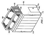
図1に、冷却モジュール例100及び冷気列封入構造例106を示す。冷気列封入構造106は、フレーム、パネル、ドア、及びサーバラックポートを有することができる。サーバラックポートは、冷気列封入構造106上の開口部であり、サーバラックに接続することができる。冷気列封入構造106は、鋼鉄、複合材料、又は炭素材などの様々な材料で作成することができ、これらの材料が、ラックマウント式ユニットを内部空間と連結できるようにする少なくとも1つのサーバラックポートを含む内部空間を定めるハウジングを形成する。いくつかの実施形態では、冷気列封入構造106を床面に直接設置することができ、データセンタ冷却室内に、冷却した空気のための上げ床が不要となる。他の実施形態では、高くした下地床を使用することができる。
FIG. 1 shows a cooling module example 100 and a cold row encapsulation structure example 106. The cold
冷気列封入構造106の上部には、冷却モジュール100を配置して位置付け、冷気列封入構造106の上面に接続することができる。冷却モジュール100は、1又はそれ以上の冷却コイル102を含む。冷却コイル102内を通る流体を使用して、冷却モジュール100を通過する相対的に熱い空気との間で熱を交換し、これにより空気を冷却する。1つの実施形態では、冷却モジュール100が、内部に冷却コイル102を配置したエンクロージャをさらに含むことができる。冷却モジュールエンクロージャは、空気がエンクロージャに入るときに通過する1又はそれ以上の開口部104を有することができる。いくつかの実施形態では、開口部104が空気フィルタを含むことができる。冷却モジュールのエンクロージャは、冷気列封入構造106の上面に接続された1又はそれ以上の開口部を有することができ、ここを通って冷気が冷却モジュールから出て、冷気列封入構造により定められる内部空間に入り込む。
The
いくつかの実施形態では、冷却コイル102内で、水を熱交換器として使用する。水ポンプ、水冷設備、及び付随する配管設備(図示せず)が、冷却した水を冷却コイル102に供給する。他の実施形態では、冷却コイル102内で、水グリコール水溶液、蒸気、又は冷却剤などの他の種類の液体又は流体を熱交換器として使用することができる。
In some embodiments, water is used as a heat exchanger within the cooling
いくつかの実施形態では、冷却コイル102を、蛇行形状の管路とすることができる。他の実施形態では、冷却コイル102を、直線の管路などの他の形状とすることができる。冷気列封入構造106のサイズ、冷却要件、気流の速度、及び冷却コイル102の物理的特性に応じ、冷却モジュール100の冷却コイル数を変更することができる。1つの実施形態では、冷却モジュール100内で2つの冷却コイルが使用される。
In some embodiments, the cooling
一般に、冷気は熱気よりも重いので、一般に、冷却コイル102により冷却された冷気は、冷却モジュール100の下側に位置してこれに接続することができる冷気列封入構造106により定められた内部空間内へ下向きに移動する。冷気列封入構造106は、内部空間を定めるエンクロージャを含む。このエンクロージャは、複数のサーバラックに連結するように構成された少なくとも1つのサーバラックポート110を含む。サーバラックポート110は、サーバラックの前面が、冷気列封入構造106の内部空間と交わるようにしてサーバラックに連結するように構成される。1つの実施形態では、サーバラックポート110に6つの標準的サーバラックを接続することができる。別の実施形態では、サーバラックポート110に12個の標準的サーバラックを接続することができる。ラック内にサーバを設置して、冷気列封入構造106からの調整空気を前面において引き込み、ラックの背後において熱を放出する前後気流パターンを実現する。
In general, since the cold air is heavier than the hot air, generally, the cold air cooled by the cooling
1つの実施形態では、冷気列封入構造106が、複数のサーバラックポート110を含むことができる。サーバラックポート110は、サーバの前面、又はサーバ内に設置された他の装置が、冷気列封入構造106により定められる内部空間に連結されるようにしてサーバラックに係合することができる。この構成により前後気流パターンが実現され、図4に示すように、サーバ又はその他のラックマウント式ユニットの冷却ファンが内部空間から空気を引き込み、(単複の)プロセッサ及びその他の構成部品により加熱された空気を後部パネルから排気する。いくつかの実施形態では、サーバラック及び冷気列封入構造を、図6に示すように1又はそれ以上の接続クリップによって接続し、冷気列封入構造106の内部空間内の調整された冷気が、サーバ内のサーバファンによって引き込まれてサーバを冷却するようにすることができる。他の実施形態では、冷気列封入構造106の内部空間内の調整された冷気を、サーバ内のサーバファンによってサーバに引き込むことができるように、サーバラック及び冷気列封入構造106が隣同士に配置される。冷気列封入構造106の上部にある冷却モジュール100に相対的に熱い空気が循環され、冷却コイル102との間で熱を交換する。冷却モジュール100からの冷気が冷気列封入構造106に沈み込み、サーバ内のサーバファンによってサーバの後部に引き込まれる。いくつかの実施形態では、サーバ及びその他の機材がサーバラックにまばらに装着される。サーバ及びその他の設備は、ラック内で縦に積み重ねられるので、まばらにすることで、冷気列封入構造の内部空間に対して開いた隙間が形成され得る。冷気列封入構造106の内部空間から冷気が漏出し、熱気が循環して内部空間に戻ることにより、冷却効率が低下する恐れがある。空気の漏れを防ぐために、冷気列封入構造から隙間を通じて空気が逃げたり入ったりするのを防ぐ、サーバラックに取り付けたパネルによって隙間を塞ぐことができる。
In one embodiment, the cold
1つの実施形態では、冷気列封入構造106が、底部に安定性制御ユニット114をさらに含むことができる。安定性制御ユニット114は、地震などの自然災害中の地震動に耐える構造の構成部品を含むことができる。いくつかの実施形態では、安定性制御ユニット114が、冷気列封入構造106を容易に動かすために素早く解放できるスクロール用装置を有することができる。安定性制御ユニット114を使用した場合、冷気列封入構造106が地面から持ち上がることがある。この結果、冷気が漏れて、冷気列封入構造106の底部側から熱気が入り込む可能性がある。空気の漏れを防ぐために、1つの実施形態では、底面をシールするパネルによって冷気列封入構造106の底部側を取り囲み、このパネル上に安定性制御ユニット114を取り付けることができる。
In one embodiment, the cold
1つの実施形態では、冷気列封入構造106のエンクロージャに1又はそれ以上のドア108を設置することができる。データセンタの職員が、サーバのメンテナンスなどの様々な任務で冷気列封入構造に入ることができるように、ドア108を開閉することができる。ドア108は、冷気列封入構造106から冷気が漏れるのを防ぐように保護することができる。
In one embodiment, one or
冷気列封入構造106の寸法は、所望の数のサーバラック及びサーバの冷却要件などに応じて大きく変更することができる。1つの実施形態では、冷気列封入構造106のそれぞれのサーバラックポート110に6個〜12個の標準的サーバラックを接続することができる。冷気列封入構造の反対側のサーバラックポートには、別の6個〜12個の標準的サーバラックを接続することができる。対向するサーバラックポート間の距離は、4フィートとすることができる。冷気列封入構造106の高さは12フィートとすることができ、深さも12フィートとすることができる。
The dimensions of the cold
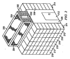
図2に、冷却モジュール例200、冷気列封入構造206、及びサーバラック208及び210を示す。この例におけるシステムは、冷気列封入構造206のサーバラックポートに嵌め込まれた形でサーバラックを示している点を除き、図1に示すものに類似する。この一体型サーバラック208及び210内にサーバを設置して、前後気流パターンを実現することができる。一体型サーバラック208及び210の前面は、冷気列封入構造206の内部空間と交わる。サーバ内のサーバファンが、冷気列封入構造206から冷気を引き込んでサーバを冷却し、サーバラックの後部から相対的に熱い空気を吐き出す。熱気は、次に1又はそれ以上の開口部204を通じて冷却モジュール200に循環し、1又はそれ以上の冷却コイル202との間で熱を交換する。冷却モジュール200は、冷気列封入構造206の上部に位置することができ、冷気列封入構造206の上部側及び冷却モジュール200の底部側にある開口部を通じて冷気列封入構造206の上面に接続することができる。一般に冷気は、特にサーバファンが冷気列封入構造から冷気を引き込んで、冷気列封入構造206の内部空間内に低い気圧を生じた場合、下方へ動く。
FIG. 2 shows an
図3に、冷却モジュール例300、冷気列封入構造302、サーバラック304、及びサーバラック上に配置されたサーバ例306を示す。このシステム例は、図2に示すものに類似する。冷気列封入構造302の上部に配置された冷却モジュール300を通じて、調整冷気が冷気列封入構造302に入り込む。サーバ306内のサーバファンが、冷気列封入構造302の内部空間から調整冷気を引き込んでサーバ306を冷却する。
FIG. 3 shows an
図4には、冷却モジュール例400、冷却コイル402、サーバ404及びサーバ404内のサーバファン406を示す。冷却モジュール400及び冷却コイル402からの調整冷気がサーバファン406によって引き込まれ、サーバ404を通過してサーバを冷却する。その後、サーバファン406により、相対的に熱い空気がサーバ404から吐き出される。
FIG. 4 shows an exemplary cooling module 400, a cooling
上記で開示したように、図1及び図2に示す冷却システムは、データセンタサーバ冷却室により定められる内部空間内で動作して、データセンタサーバ冷却室の内部空間から空気を引き込み、冷却した空気を冷気列封入構造106の内部に与えることができる。しかしながら、いくつかの実施構成では、冷却システムが、外気の使用を可能にする気流制御を含むデータセンタサーバ冷却室に関連して動作することもできる。図5に、1又はそれ以上の天井排気ファン516と、外気の吸気を制御する天井ダンパ514と、混合チャンバ518と、混合チャンバ518に入る空気の循環を制御するダンパ512とを有するデータセンタサーバ冷却室例500を示す。冷却モジュール502が、1又はそれ以上の冷却コイル504を含み、混合チャンバ518に接続される。冷気列封入構造506の上面が、冷却モジュール502に接続される。冷気列封入構造506のエンクロージャ上のサーバラックポート508が、サーバラック510に接続される。このサーバラック内にサーバを設置して、前後気流パターンを実現することができる。サーバラックの前面は、冷気列封入構造506の内部空間と交わる。サーバ内のサーバファンが、冷気列封入構造506から冷気を引き込んでサーバを冷却し、サーバラックから熱気を放出する。
As disclosed above, the cooling system shown in FIGS. 1 and 2 operates in an internal space defined by the data center server cooling chamber, draws air from the internal space of the data center server cooling chamber, and cools the air. Can be provided inside the cold
サーバ冷却室500は、2つのモードで動作することができる。1つのモードでは、サーバ冷却室500に外気が導入されず、サーバから放出された熱気が、混合チャンバ518及び冷却モジュール502に循環して戻される。別のモードでは、サーバ冷却室500に外部冷気が導入される。混合チャンバ上のダンパ512が閉じている間、天井ダンパ514が開く。外部冷気が、冷却モジュール502を通過して冷気列封入構造506に入る。
The
1つの実施形態では、天井ダンパ514が閉じて、混合チャンバ上のダンパ512が開く。サーバにより放出された熱気の一部は、1又はそれ以上の天井排気ファン516を通じてサーバ冷却室500の外部に排気され、熱気の一部は、開いたダンパ512を通じて混合チャンバ518に入り込む。混合チャンバ内の熱気が冷却モジュール502に引き込まれ、冷却コイル504との間で熱を交換する。その後、重力及び冷気列封入構造506の内部空間内の低い気圧によって、冷気が冷気列封入構造506に入り込む。
In one embodiment, the
別の実施形態では、天井ダンパ514が開いて、混合チャンバのダンパ512が閉じる。外部冷気が、開いたダンパ514を通じて混合チャンバ518に入り込み、冷却モジュール504を通過して、冷気列封入構造506の内部空間に沈み込む。
In another embodiment, the
いくつかの実施形態では、ダンパ512及び514の開閉を、温度制御ユニットによって制御することができる。外部温度が適当なレベルに達すると、温度制御ユニットが天井ダンパ514を開いて室内に外気が入るようにし、混合チャンバ上のダンパ512を閉じて、サーバから放出された熱気が混合チャンバに入り込まないようにする。外部温度がサーバ冷却室500にとって熱すぎる場合、温度制御ユニットが天井ダンパ514を閉じて、熱い外気が室内に導入されるのを防ぎ、ダンパ512を開いて、サーバから熱気が放出されて混合チャンバに戻るようにする。外部の自然な冷気を利用することで、データセンタのエネルギー消費量が大幅に削減され、冷却モジュール100を通じて循環する液体を冷却する必要性が減少する。いくつかの実施形態では、ダンパ512及び514の開閉、及び天井排気ファン516の動作が全て、サーバ冷却室の内部及び外部の温度をモニタし、部屋を冷却する上で最適な効率を達成するようにダンパ及びファンを動作させる温度制御ユニットなどの電子機器によって制御される。
In some embodiments, the opening and closing of the
データセンタの所在位置によっては、外部冷気の湿度が異なる場合がある。外部冷気の湿度が低い場合には、湿度レベルが信頼できるサーバ動作のための要件を満たすように外部空気を調整する必要があり得る。サーバメーカーは、信頼できるサーバ設備の動作のための湿度要件を大幅に緩和しているが、データセンタ内の設備の性能及び信頼性にとって、データセンタサーバ冷却室内の適切な外気湿度は依然として重要である。いくつかの実施形態では、混合チャンバ518内に1又はそれ以上の加湿機を設置して、混合チャンバを通過する空気中の湿気を調整することができる。
Depending on the location of the data center, the humidity of the external cold air may differ. If the humidity of the external cold air is low, it may be necessary to adjust the external air so that the humidity level meets the requirements for reliable server operation. Although server manufacturers have greatly relaxed humidity requirements for reliable server equipment operation, proper outside air humidity in the data center server cooling room is still important to the performance and reliability of the equipment in the data center. is there. In some embodiments, one or more humidifiers can be installed in the mixing
図6に、サーバラックポートの上端を横切って、及びこれに近接して水平に延びる上部クロスバーとサーバラックの上部クロスバーとを接続する1又はそれ以上の接続クリップ606を有する冷却システム例を示す。図6では、ラックに係合するように構成されたサーバラックポートを含む冷気列封入構造612の上部に冷却モジュール600が配置される。1又はそれ以上のサーバラック614がサーバラックポートに嵌め込まれた場合、冷気列封入構造の上部クロスバー602が、サーバラック614の1又はそれ以上の上部クロスバー604に係合する。1又はそれ以上の接続クリップ606を使用して、1又はそれ以上のサーバラック614の上部クロスバーを、冷気列封入構造612の上部クロスバーに素早く固定する。同様に、冷気列封入構造の下部クロスバー618を、サーバラックの下部クロスバー620に係合させることもできる。1又はそれ以上の接続クリップ616を使用して、1又はそれ以上のサーバラック614の下部クロスバーを、冷気列封入構造612の下部クロスバーに素早く固定する。
FIG. 6 illustrates an exemplary cooling system having one or more connection clips 606 that connect an upper crossbar that extends horizontally across and adjacent to the upper end of the server rack port and the upper crossbar of the server rack. Show. In FIG. 6, a cooling module 600 is disposed on top of a cold row encapsulation structure 612 that includes a server rack port configured to engage a rack. When one or
いくつかの実施形態では、接続クリップがU字形の断面形状を有することができる。このU字形接続クリップを、2つのクロスバーを固定するための留め具として使用することができる。U字形接続クリップの一方の側に1又はそれ以上のピン部材608を締め付け、この接続クリップを締め付けて接続を固定することができる。ピン部材608は、金属ボルトとすることができる。接続クリップ606は、鋼鉄などの金属で作成することができる。接続クリップの幅は、冷気列封入構造の上部又は下部クロスバーと、サーバラックの上部又は下部クロスバーとを組み合わせた幅に見合うものにすることができる。接続クリップは、サーバラックを冷気列封入構造に固定するための迅速かつ容易な機構を提供する。
In some embodiments, the connecting clip can have a U-shaped cross-sectional shape. This U-shaped connection clip can be used as a fastener for securing the two crossbars. One or more pin members 608 can be tightened on one side of the U-shaped connection clip and the connection clip can be tightened to secure the connection. The pin member 608 can be a metal bolt. The
図7に、2つのクロスバーを固定する接続クリップ例を示す。U字形接続クリップ704を使用して、クロスバー700とクロスバー702を固定する。いくつかの実施形態では、クロスバー700を、冷気列封入構造の上部クロスバーとし、クロスバー702を、冷気列封入構造のサーバラックポートに嵌め込まれたサーバラックの上部クロスバーとすることができる。クロスバー700及び702は、鋼鉄などの金属で作成することができる。接続クリップ704の幅は、クロスバー700とクロスバー702を組み合わせた幅に見合うものにすることができる。接続クリップ上の2つのピン部材706は、クロスバー700及び702の接続を固定するために2つのソケットを通じて締め付けることができる金属ボルトを含むことができる。いくつかの実施形態では、接続クリップ上に2つよりも多くのピン部材を使用することができる。
FIG. 7 shows an example of a connection clip for fixing two crossbars. A
図8に、2つのクロスバーを固定する接続クリップ例を示す。U字形接続クリップ804を使用して、クロスバー800とクロスバー802を固定する。いくつかの実施形態では、クロスバー800を、冷気列封入構造の下部クロスバーとし、クロスバー802を、冷気列封入構造のサーバラックポートに嵌め込まれたサーバラックの下部クロスバーとすることができる。クロスバー800及び802は、鋼鉄などの金属で作成することができる。接続クリップ804の幅は、クロスバー800とクロスバー802を組み合わせた幅に見合うものにすることができる。接続クリップの2つのピン部材806は、クロスバー800及び802の接続を固定するために2つのソケットを通じて締め付けることができる金属ボルトを含むことができる。いくつかの実施形態では、接続クリップ上に2つよりも多くのピン部材を使用することができる。
FIG. 8 shows an example of a connection clip for fixing two crossbars. A
特定の実施形態を参照しながら本発明について説明した。例えば、特定の構成部品及び構成を参照しながら本発明の実施形態を説明したが、当業者であれば、異なる組み合わせの構成部品及び構成も使用できることを理解するであろう。当業者には他の実施形態が明白であろう。従って、本発明が、添付の特許請求の範囲によって示すもの以外に限定されることは意図していない。 The invention has been described with reference to particular embodiments. For example, while embodiments of the invention have been described with reference to particular components and configurations, those skilled in the art will appreciate that different combinations of components and configurations may be used. Other embodiments will be apparent to those skilled in the art. Accordingly, it is not intended that the invention be limited except as indicated by the appended claims.
500 データセンタサーバ冷却室
502 冷却モジュール
504 冷却コイル
506 冷気列封入構造
508 サーバラックポート
510 サーバラック
512 ダンパ
514 天井ダンパ
516 天井排気ファン
518 混合チャンバ
500 Data center
Claims (10)
前記エンクロージャにより定められる前記内部空間に冷却空気を供給する冷却及び混合モジュールと、
1つの上部クロスバー及び1つの下部クロスバー及び1又はそれ以上のラックマウント式サーバを内部に設置し、前記エンクロージャにより定められる前記内部空間に前記1又はそれ以上のラックマウント式サーバのそれぞれの前面が連結するように前記ラックポートに嵌め込まれた複数のサーバラックと、
前記1又はそれ以上のラックマウント式サーバの前記それぞれの前面を通じて前記内部空間から空気を引き込み、前記1又はそれ以上のラックマウント式サーバから加熱空気を放出する1又はそれ以上の冷却ファンと、
それぞれのサーバラックの前記上部クロスバーを前記エンクロージャの前記上部クロスバーに固定する第1の接続クリップと、
それぞれのサーバラックの前記下部クロスバーを前記エンクロージャの前記下部クロスバーに固定する第2の接続クリップと、
を備えることを特徴とするサーバ冷却システム。 An upper crossbar having an interior space and having a rack port configured to engage a plurality of server racks and extending horizontally across and adjacent to an upper end of the rack port; An enclosure further comprising a lower crossbar extending horizontally across and adjacent to a lower end of the rack port;
A cooling and mixing module for supplying cooling air to the internal space defined by the enclosure;
The one upper cross bar and one bottom cross bar and one or more rack mounted servers installed therein, each of the front surface of the one or more rack mounted servers in the internal space defined by the enclosure A plurality of server racks fitted in the rack port so that
The one or draws more rack mounted air from said interior space the through each of the front of the server, and one or more cooling fans to release heated air from said one or more rack mounted server,
The upper cross bar of each server rack and the first connecting clip for fixing on said Buk crossbar of the enclosure,
A second connection clip for securing the lower crossbar of each server rack to the lower crossbar of the enclosure;
A server cooling system comprising:
1又はそれ以上のピン部材と、
前記ピン部材を受け入れるための1又はそれ以上のソケットをさらに含む留め具部材と、
を含み、前記留め具部材が、前記ソケットの前記ピン部材を通じて前記サーバラックの前記上部クロスバーを前記エンクロージャの前記上部クロスバーに固定する、
ことを特徴とする請求項1に記載のサーバ冷却システム。 The first connecting clip has a U-shaped cross-sectional shape;
One or more pin members;
A fastener member further comprising one or more sockets for receiving the pin member;
Wherein the said fastener member to secure the upper cross bar of the server rack through the pin member of said socket on said Buk crossbar of the enclosure,
The server cooling system according to claim 1.
ことを特徴とする請求項1に記載のサーバ冷却システム。 It said rack port is configured to substantially conform to the outer periphery of the plurality of Sabara click,
The server cooling system according to claim 1.
ことを特徴とする請求項3に記載のサーバ冷却システム。 The rack port can be substantially sealed when attached to the server rack,
The server cooling system according to claim 3.
ことを特徴とする請求項4に記載のサーバ冷却システム。 The rack port includes one or more gaskets configured to substantially seal the plurality of server racks with the rack port;
The server cooling system according to claim 4.
前記冷却モジュール内で外気を冷却するようになっている1又はそれ以上の一体型コイルと、
前記冷却モジュール内外の前記空気の流れを調整するようになっている1又はそれ以上の一体型ダンパと、
前記一体型ダンパの動作を制御する制御ユニットと、
をさらに含むことを特徴とする請求項1に記載のサーバ冷却システム。 The cooling and mixing module is
One or more integrated coils adapted to cool the outside air in the cooling module;
One or more integrated dampers adapted to regulate the flow of air inside and outside the cooling module;
A control unit for controlling the operation of the integrated damper;
The server cooling system according to claim 1, further comprising:
ことを特徴とする請求項6に記載のサーバ冷却システム。 Cooling the outside air using liquid in the integrated coil;
The server cooling system according to claim 6.
ことを特徴とする請求項6に記載のサーバ冷却システム。 The integrated damper is controlled by a temperature control unit;
The server cooling system according to claim 6.
1又はそれ以上のピン部材と、
前記ピン部材を受け入れるための1又はそれ以上のソケットをさらに含む留め具部材と、
を含み、前記留め具部材が、前記ソケットの前記ピン部材を通じて前記サーバラックの前記下部クロスバーを前記エンクロージャの前記下部クロスバーに固定する、
ことを特徴とする請求項1に記載のサーバ冷却システム。 The second connection clip has a U-shaped cross-sectional shape;
One or more pin members;
A fastener member further comprising one or more sockets for receiving the pin member;
And the fastener member secures the lower crossbar of the server rack to the lower crossbar of the enclosure through the pin member of the socket.
The server cooling system according to claim 1.
前記エンクロージャにより定められる前記内部空間に外部の自然な冷気を供給する冷却及び混合モジュールと、
1つの上部クロスバー及び1つの下部クロスバー及び1又はそれ以上のラックマウント式サーバを内部に設置し、前記エンクロージャにより定められる前記内部空間に前記1又はそれ以上のラックマウント式サーバのそれぞれの前面が連結するように前記ラックポートに嵌め込まれた複数のサーバラックと、
前記1又はそれ以上のラックマウント式サーバの前記それぞれの前面を通じて前記内部空間から空気を引き込み、前記1又はそれ以上のラックマウント式サーバから加熱空気を放出する1又はそれ以上の冷却ファンと、
それぞれのサーバラックの前記上部クロスバーを前記エンクロージャの前記上部クロスバーに固定する第1の接続クリップと、
それぞれのサーバラックの前記下部クロスバーを前記エンクロージャの前記下部クロスバーに固定する第2の接続クリップと、
を備えることを特徴とするサーバ冷却室。 An upper crossbar that defines an interior space and has a rack port configured to engage a plurality of server racks, and extends horizontally across and adjacent to an upper end of the rack port; An enclosure further comprising a lower crossbar extending horizontally across and adjacent to the lower end of the rack port;
And cooling and mixing module supplies the natural cold air of the external into the internal space defined by said enclosure,
The one upper cross bar and one bottom cross bar and one or more rack mounted servers installed therein, each of the front surface of the one or more rack mounted servers in the internal space defined by the enclosure A plurality of server racks fitted in the rack port so that
The one or draws more rack mounted air from said interior space the through each of the front of the server, and one or more cooling fans to release heated air from said one or more rack mounted server,
The upper cross bar of each server rack and the first connecting clip for fixing on said Buk crossbar of the enclosure,
A second connection clip for securing the lower crossbar of each server rack to the lower crossbar of the enclosure;
A server cooling room comprising:
Applications Claiming Priority (3)
| Application Number | Priority Date | Filing Date | Title |
|---|---|---|---|
| US12/427,655 | 2009-04-21 | ||
| US12/427,655 US7800900B1 (en) | 2009-04-21 | 2009-04-21 | Cold row encapsulation for server farm cooling system |
| PCT/US2010/029356 WO2010123661A2 (en) | 2009-04-21 | 2010-03-31 | Cold row encapsulation for server farm cooling system |
Related Child Applications (1)
| Application Number | Title | Priority Date | Filing Date |
|---|---|---|---|
| JP2015094195A Division JP6018257B2 (en) | 2009-04-21 | 2015-05-01 | Cold train encapsulation for server farm cooling system |
Publications (2)
| Publication Number | Publication Date |
|---|---|
| JP2012524939A JP2012524939A (en) | 2012-10-18 |
| JP5745502B2 true JP5745502B2 (en) | 2015-07-08 |
Family
ID=42733937
Family Applications (3)
| Application Number | Title | Priority Date | Filing Date |
|---|---|---|---|
| JP2012507235A Expired - Fee Related JP5745502B2 (en) | 2009-04-21 | 2010-03-31 | Cold train encapsulation for server farm cooling system |
| JP2015094195A Expired - Fee Related JP6018257B2 (en) | 2009-04-21 | 2015-05-01 | Cold train encapsulation for server farm cooling system |
| JP2016168179A Expired - Fee Related JP6223519B2 (en) | 2009-04-21 | 2016-08-30 | Cold train encapsulation for server farm cooling system |
Family Applications After (2)
| Application Number | Title | Priority Date | Filing Date |
|---|---|---|---|
| JP2015094195A Expired - Fee Related JP6018257B2 (en) | 2009-04-21 | 2015-05-01 | Cold train encapsulation for server farm cooling system |
| JP2016168179A Expired - Fee Related JP6223519B2 (en) | 2009-04-21 | 2016-08-30 | Cold train encapsulation for server farm cooling system |
Country Status (11)
| Country | Link |
|---|---|
| US (1) | US7800900B1 (en) |
| EP (1) | EP2422258B1 (en) |
| JP (3) | JP5745502B2 (en) |
| KR (1) | KR101346450B1 (en) |
| CN (2) | CN104536549B (en) |
| HK (2) | HK1167481A1 (en) |
| MY (1) | MY154666A (en) |
| RU (1) | RU2531877C2 (en) |
| SG (1) | SG175237A1 (en) |
| TW (3) | TWI624752B (en) |
| WO (1) | WO2010123661A2 (en) |
Families Citing this family (59)
| Publication number | Priority date | Publication date | Assignee | Title |
|---|---|---|---|---|
| US7804685B2 (en) | 2005-09-19 | 2010-09-28 | Chatsworth Products, Inc. | Ducted exhaust equipment enclosure |
| US7542287B2 (en) | 2005-09-19 | 2009-06-02 | Chatsworth Products, Inc. | Air diverter for directing air upwardly in an equipment enclosure |
| US11259446B2 (en) | 2005-09-19 | 2022-02-22 | Chatsworth Products, Inc. | Vertical exhaust duct for electronic equipment enclosure |
| US8107238B2 (en) | 2005-09-19 | 2012-01-31 | Chatsworth Products, Inc. | Ducted exhaust equipment enclosure |
| US11212928B2 (en) | 2005-09-19 | 2021-12-28 | Chatsworth Products, Inc. | Vertical exhaust duct for electronic equipment enclosure |
| US9148980B2 (en) * | 2007-07-13 | 2015-09-29 | Dell Products L.P. | System for a rack design |
| WO2009103090A2 (en) | 2008-02-14 | 2009-08-20 | Chatsworth Products, Inc. | Air directing device |
| US9072200B2 (en) * | 2008-09-10 | 2015-06-30 | Schneider Electric It Corporation | Hot aisle containment panel system and method |
| US8184435B2 (en) | 2009-01-28 | 2012-05-22 | American Power Conversion Corporation | Hot aisle containment cooling system and method |
| US8054625B2 (en) | 2009-04-21 | 2011-11-08 | Yahoo! Inc. | Cold row encapsulation for server farm cooling system |
| US10212858B2 (en) | 2009-04-21 | 2019-02-19 | Excalibur Ip, Llc | Cold row encapsulation for server farm cooling system |
| US8360833B2 (en) * | 2009-05-28 | 2013-01-29 | American Power Conversion Corporation | Method and apparatus for attachment and removal of fans while in operation and without the need for tools |
| US8031468B2 (en) * | 2009-06-03 | 2011-10-04 | American Power Conversion Corporation | Hot aisle containment cooling unit and method for cooling |
| US7944692B2 (en) * | 2009-06-12 | 2011-05-17 | American Power Conversion Corporation | Method and apparatus for installation and removal of overhead cooling equipment |
| US7990709B2 (en) * | 2009-09-23 | 2011-08-02 | International Business Machines Corporation | Apparatus and method for facilitating cooling of an electronics rack |
| FR2954670B1 (en) * | 2009-12-22 | 2017-06-09 | Atrium Data | METHOD AND DEVICE FOR REDUCING THE ENERGY CONSUMPTION OF A CENTER COMPRISING ENERGY EQUIPMENT. |
| US7986526B1 (en) * | 2010-02-25 | 2011-07-26 | International Business Machines Corporation | Acoustically absorptive apparatus for an electronics rack of a data center |
| JP5610839B2 (en) * | 2010-05-11 | 2014-10-22 | 株式会社日立製作所 | Cooling system |
| US8628154B2 (en) * | 2010-05-13 | 2014-01-14 | Panduit Corp. | Aisle containment system |
| US20110300788A1 (en) * | 2010-06-03 | 2011-12-08 | Panduit Corp. | Vertical Exhaust Duct |
| TW201210433A (en) * | 2010-08-18 | 2012-03-01 | Hon Hai Prec Ind Co Ltd | Computer server cabinet |
| TW201209545A (en) * | 2010-08-23 | 2012-03-01 | Hon Hai Prec Ind Co Ltd | Computer server cabinet |
| US9332678B2 (en) | 2010-09-30 | 2016-05-03 | International Business Machines Corporation | Cold air containment system in a data centre |
| US9655259B2 (en) * | 2011-12-09 | 2017-05-16 | Chatsworth Products, Inc. | Data processing equipment structure |
| US8480775B2 (en) | 2010-12-20 | 2013-07-09 | Microsoft Corporation | Self cleaning fan assembly |
| AU2011355562B2 (en) | 2011-01-11 | 2017-03-30 | Schneider Electric It Corporation | Cooling unit and method |
| JP2013104639A (en) * | 2011-11-16 | 2013-05-30 | Toshiba Corp | Air conditioning system and air conditioning control method for server room management |
| US9429335B2 (en) * | 2012-01-11 | 2016-08-30 | Hewlett Packard Enterprise Development Lp | Adiabatic cooling unit |
| US10123464B2 (en) | 2012-02-09 | 2018-11-06 | Hewlett Packard Enterprise Development Lp | Heat dissipating system |
| KR20140132333A (en) | 2012-03-12 | 2014-11-17 | 휴렛-팩커드 디벨롭먼트 컴퍼니, 엘.피. | Liquid temperature control cooling |
| WO2013148884A1 (en) * | 2012-03-27 | 2013-10-03 | LDM Products, Inc. | Monitoring and controlling data center components |
| WO2013150583A1 (en) | 2012-04-02 | 2013-10-10 | 富士通株式会社 | Module-type data center |
| CN103429022B (en) * | 2012-05-23 | 2016-09-07 | 华为技术有限公司 | A kind of container data center |
| WO2014051604A1 (en) | 2012-09-28 | 2014-04-03 | Hewlett-Packard Development Company, L.P. | Cooling assembly |
| WO2014070176A1 (en) | 2012-10-31 | 2014-05-08 | Hewlett-Packard Development Company, L.P. | Modular rack system |
| US9072193B1 (en) | 2012-11-20 | 2015-06-30 | Amazon Technologies, Inc. | Datacenter aisle containment structure |
| US20140196394A1 (en) | 2013-01-11 | 2014-07-17 | Chatsworth Products, Inc. | Modular thermal isolation barrier for data processing equipment structure |
| CN107743351B (en) | 2013-01-31 | 2020-11-06 | 慧与发展有限责任合伙企业 | Apparatus for providing liquid cooling, cooling system and method for cooling |
| US9198310B2 (en) | 2013-03-11 | 2015-11-24 | Amazon Technologies, Inc. | Stall containment of rack in a data center |
| US9668375B2 (en) * | 2013-03-15 | 2017-05-30 | Yahoo! Inc. | Atmospheric cooling of servers in a data center |
| US9648784B2 (en) | 2013-03-15 | 2017-05-09 | Inertech Ip Llc | Systems and assemblies for cooling server racks |
| US9351427B2 (en) | 2013-12-17 | 2016-05-24 | Chatsworth Products, Inc. | Electronic equipment enclosure |
| US10191499B2 (en) * | 2014-07-02 | 2019-01-29 | Microsoft Technology Licensing, Llc | Gas distribution system within temperature differentiated environments |
| CN104837318A (en) * | 2015-05-04 | 2015-08-12 | 亚翔系统集成科技(苏州)股份有限公司 | Modular data processing center and air-conditioning method thereof |
| US9769953B2 (en) * | 2016-02-04 | 2017-09-19 | Google Inc. | Cooling a data center |
| SG11201807975UA (en) | 2016-03-16 | 2018-10-30 | Inertech Ip Llc | System and methods utilizing fluid coolers and chillers to perform in-series heat rejection and trim cooling |
| US10130006B2 (en) * | 2016-04-21 | 2018-11-13 | Hanon Systems | Thermal control within an enclosure with circular cross-section |
| RU2621360C1 (en) * | 2016-05-20 | 2017-06-02 | Федеральное государственное унитарное предприятие "18 Центральный научно-исследовательский институт" Министерства обороны Российской Федерации | Modular submersible cooling system |
| US10238008B2 (en) * | 2016-11-08 | 2019-03-19 | Ortronics, Inc. | Containment systems and related methods of use |
| DE102017104538A1 (en) * | 2017-03-03 | 2018-09-06 | Apelsin Enterprises GmbH | Arrangement of a cooling system for cooling at least one, in a room arranged server cabinet |
| DE102017115693A1 (en) * | 2017-07-12 | 2019-01-17 | CoinBau GmbH | Temperable module for a data center, data center and process for temperature control of a data center |
| CN107291195A (en) * | 2017-07-25 | 2017-10-24 | 合肥红铭网络科技有限公司 | A kind of high-performance server heat abstractor |
| CN107479649A (en) * | 2017-08-02 | 2017-12-15 | 合肥红铭网络科技有限公司 | A kind of main frame cooling cabinet |
| WO2019113657A1 (en) * | 2017-12-14 | 2019-06-20 | Diaferia Flavio Albertini | Enclosure system for hot and cold aisles in a data processing centre |
| CN108601287B (en) * | 2018-02-11 | 2020-08-28 | 北京百度网讯科技有限公司 | Overhead refrigeration method and overhead refrigeration unit |
| US11497145B2 (en) | 2018-08-21 | 2022-11-08 | National University Of Singapore | Server rack and data center including a hybrid-cooled server |
| WO2020163968A2 (en) | 2019-02-15 | 2020-08-20 | Scot Arthur Johnson | Transportable datacenter |
| US11910557B2 (en) * | 2019-02-15 | 2024-02-20 | Digital Shovel Holdings Inc. | Transportable datacenter |
| CA3183109A1 (en) | 2019-05-15 | 2020-11-19 | Upstream Data Inc. | Portable blockchain mining system and methods of use |
Family Cites Families (48)
| Publication number | Priority date | Publication date | Assignee | Title |
|---|---|---|---|---|
| DE709149C (en) * | 1940-04-30 | 1941-08-07 | Carl Kupfer | Butt connection for wooden supports, stiffeners, struts, etc. like |
| GB1214388A (en) * | 1967-10-26 | 1970-12-02 | Internat Standard Electrical E | Cabinet for electrical equipment |
| JPH02104679U (en) * | 1989-02-03 | 1990-08-20 | ||
| JPH03124685U (en) * | 1990-03-28 | 1991-12-17 | ||
| SE9304264L (en) | 1993-12-22 | 1995-06-23 | Ericsson Telefon Ab L M | Method and apparatus for cooling in closed rooms |
| US5570865A (en) * | 1994-09-16 | 1996-11-05 | Godfrey; Kenneth E. | Article restraint and fall prevention device |
| JP3832001B2 (en) * | 1996-12-19 | 2006-10-11 | 石川島播磨重工業株式会社 | Restraint device for manhole block of exhaust gas boiler |
| JP3605492B2 (en) * | 1997-03-12 | 2004-12-22 | 新日本製鐵株式会社 | Steel formwork for forming tubular concrete structures |
| US6131647A (en) | 1997-09-04 | 2000-10-17 | Denso Corporation | Cooling system for cooling hot object in container |
| US6034873A (en) | 1998-06-02 | 2000-03-07 | Ericsson Inc | System and method for separating air flows in a cooling system |
| EP1065027A1 (en) | 1999-02-18 | 2001-01-03 | Lns S.A. | Short bar feeder for machine-tool |
| TW444886U (en) * | 1999-06-21 | 2001-07-01 | Image & Amp Shapetek Co Ltd | Fixed structure for computer motherboard rack |
| GB2354062A (en) | 1999-09-13 | 2001-03-14 | British Broadcasting Corp | Cooling system for use in cooling electronic equipment |
| US6557357B2 (en) | 2000-02-18 | 2003-05-06 | Toc Technology, Llc | Computer rack heat extraction device |
| US6494050B2 (en) | 2000-02-18 | 2002-12-17 | Toc Technology, Llc | Computer rack heat extraction device |
| DE10008383A1 (en) | 2000-02-23 | 2001-09-06 | Loh Kg Rittal Werk | Control cabinet or housing with an air conditioning device |
| JP2002094269A (en) * | 2000-07-12 | 2002-03-29 | Shimizu Corp | Server unit |
| JP4558177B2 (en) * | 2000-11-20 | 2010-10-06 | 高砂熱学工業株式会社 | Air conditioning system for communication equipment room, etc. |
| US6374627B1 (en) * | 2001-01-09 | 2002-04-23 | Donald J. Schumacher | Data center cooling system |
| JP2002237690A (en) * | 2001-02-08 | 2002-08-23 | Shimizu Corp | Quake-absorbing trestle |
| US6525935B2 (en) | 2001-03-12 | 2003-02-25 | Appro International, Inc. | Low profile highly accessible computer enclosure with plenum for cooling high power processors |
| RU20757U1 (en) * | 2001-04-17 | 2001-11-27 | Общество с ограниченной ответственностью "Проектно-строительная фирма "РОСТВЕРК" | TELECOMMUNICATION EQUIPMENT CONTAINER |
| US6672955B2 (en) | 2001-09-07 | 2004-01-06 | International Business Machines Corporation | Air flow management system for an internet data center |
| JP3842631B2 (en) | 2001-11-30 | 2006-11-08 | 高砂熱学工業株式会社 | Air conditioning systems for communication / information processing equipment rooms, etc. |
| US20030178253A1 (en) * | 2002-03-21 | 2003-09-25 | Tatge Robert J. | Portable aircraft maintenance platform |
| US6867967B2 (en) | 2002-12-16 | 2005-03-15 | International Business Machines Corporation | Method of constructing a multicomputer system |
| JP4199018B2 (en) | 2003-02-14 | 2008-12-17 | 株式会社日立製作所 | Rack mount server system |
| US6859366B2 (en) * | 2003-03-19 | 2005-02-22 | American Power Conversion | Data center cooling system |
| US7046514B2 (en) * | 2003-03-19 | 2006-05-16 | American Power Conversion Corporation | Data center cooling |
| JP2004319628A (en) | 2003-04-14 | 2004-11-11 | Hitachi Ltd | System module |
| JP2005019562A (en) * | 2003-06-24 | 2005-01-20 | Hitachi Ltd | Cooling structure of electronic apparatus |
| US7278273B1 (en) | 2003-12-30 | 2007-10-09 | Google Inc. | Modular data center |
| US7266964B2 (en) | 2004-03-04 | 2007-09-11 | Sun Microsystems, Inc. | Data center room cold aisle deflector |
| US7003971B2 (en) | 2004-04-12 | 2006-02-28 | York International Corporation | Electronic component cooling system for an air-cooled chiller |
| DE202004006552U1 (en) * | 2004-04-26 | 2004-07-08 | Knürr AG | Cooling system for device and network cabinets |
| US7165412B1 (en) | 2004-11-19 | 2007-01-23 | American Power Conversion Corporation | IT equipment cooling |
| US7259963B2 (en) * | 2004-12-29 | 2007-08-21 | American Power Conversion Corp. | Rack height cooling |
| US7841199B2 (en) | 2005-05-17 | 2010-11-30 | American Power Conversion Corporation | Cold aisle isolation |
| US7481704B2 (en) | 2005-12-12 | 2009-01-27 | Inventec Corporation | Fan rack fixture having two pairs of positioning and locking portions |
| US7862410B2 (en) * | 2006-01-20 | 2011-01-04 | American Power Conversion Corporation | Air removal unit |
| CA2655305C (en) * | 2006-06-15 | 2014-08-26 | Valan R. Martini | Energy saving system and method for cooling computer data center and telecom equipment |
| US7430118B1 (en) | 2007-06-04 | 2008-09-30 | Yahoo! Inc. | Cold row encapsulation for server farm cooling system |
| US7688578B2 (en) * | 2007-07-19 | 2010-03-30 | Hewlett-Packard Development Company, L.P. | Modular high-density computer system |
| TWM351368U (en) * | 2008-02-21 | 2009-02-21 | Chunghwa Picture Tubes Ltd | Backlight module and the liquid crystal display device thereof |
| JP4648966B2 (en) * | 2008-08-19 | 2011-03-09 | 日立電線株式会社 | Data center |
| RU79366U1 (en) * | 2008-08-20 | 2008-12-27 | Открытое Акционерное Общество "СИТРОНИКС"-ОАО "СИТРОНИКС" | COMPUTER EQUIPMENT COOLING SYSTEM |
| JP4735690B2 (en) * | 2008-09-16 | 2011-07-27 | 日立電線株式会社 | Data center |
| JP2009079890A (en) * | 2008-10-02 | 2009-04-16 | Softbank Idc Corp | Air-conditioning system |
-
2009
- 2009-04-21 US US12/427,655 patent/US7800900B1/en not_active Expired - Fee Related
-
2010
- 2010-03-31 CN CN201410758008.4A patent/CN104536549B/en not_active Expired - Fee Related
- 2010-03-31 CN CN201080017605.1A patent/CN102483641B/en not_active Expired - Fee Related
- 2010-03-31 SG SG2011075223A patent/SG175237A1/en unknown
- 2010-03-31 MY MYPI2011004955A patent/MY154666A/en unknown
- 2010-03-31 RU RU2011142244/08A patent/RU2531877C2/en not_active IP Right Cessation
- 2010-03-31 WO PCT/US2010/029356 patent/WO2010123661A2/en active Application Filing
- 2010-03-31 KR KR1020117026798A patent/KR101346450B1/en active IP Right Grant
- 2010-03-31 EP EP10767490.5A patent/EP2422258B1/en not_active Not-in-force
- 2010-03-31 JP JP2012507235A patent/JP5745502B2/en not_active Expired - Fee Related
- 2010-04-08 TW TW105103243A patent/TWI624752B/en not_active IP Right Cessation
- 2010-04-08 TW TW102143684A patent/TWI528151B/en not_active IP Right Cessation
- 2010-04-08 TW TW099110857A patent/TWI421672B/en not_active IP Right Cessation
-
2012
- 2012-08-15 HK HK12107979.6A patent/HK1167481A1/en not_active IP Right Cessation
-
2015
- 2015-05-01 JP JP2015094195A patent/JP6018257B2/en not_active Expired - Fee Related
- 2015-09-17 HK HK15109100.1A patent/HK1208547A1/en not_active IP Right Cessation
-
2016
- 2016-08-30 JP JP2016168179A patent/JP6223519B2/en not_active Expired - Fee Related
Also Published As
| Publication number | Publication date |
|---|---|
| CN104536549A (en) | 2015-04-22 |
| MY154666A (en) | 2015-07-15 |
| HK1208547A1 (en) | 2016-03-04 |
| US7800900B1 (en) | 2010-09-21 |
| JP2015195034A (en) | 2015-11-05 |
| TW201042433A (en) | 2010-12-01 |
| WO2010123661A2 (en) | 2010-10-28 |
| CN102483641A (en) | 2012-05-30 |
| RU2531877C2 (en) | 2014-10-27 |
| JP2016219055A (en) | 2016-12-22 |
| CN102483641B (en) | 2015-01-07 |
| TWI528151B (en) | 2016-04-01 |
| RU2011142244A (en) | 2013-05-27 |
| WO2010123661A3 (en) | 2011-02-10 |
| KR20120018150A (en) | 2012-02-29 |
| HK1167481A1 (en) | 2012-11-30 |
| TW201619744A (en) | 2016-06-01 |
| EP2422258A2 (en) | 2012-02-29 |
| JP6223519B2 (en) | 2017-11-01 |
| TW201418957A (en) | 2014-05-16 |
| TWI421672B (en) | 2014-01-01 |
| JP2012524939A (en) | 2012-10-18 |
| KR101346450B1 (en) | 2014-01-02 |
| TWI624752B (en) | 2018-05-21 |
| SG175237A1 (en) | 2011-11-28 |
| JP6018257B2 (en) | 2016-11-02 |
| CN104536549B (en) | 2019-01-04 |
| EP2422258B1 (en) | 2019-01-30 |
| EP2422258A4 (en) | 2014-12-31 |
Similar Documents
| Publication | Publication Date | Title |
|---|---|---|
| JP6223519B2 (en) | Cold train encapsulation for server farm cooling system | |
| JP6290361B2 (en) | Cold train encapsulation for server farm cooling system | |
| JP6258450B2 (en) | Cold train encapsulation for server farm cooling system | |
| JP6285058B2 (en) | Cold train encapsulation for server farm cooling system |
Legal Events
| Date | Code | Title | Description |
|---|---|---|---|
| A621 | Written request for application examination |
Free format text: JAPANESE INTERMEDIATE CODE: A621 Effective date: 20130401 |
|
| A131 | Notification of reasons for refusal |
Free format text: JAPANESE INTERMEDIATE CODE: A131 Effective date: 20140326 |
|
| A601 | Written request for extension of time |
Free format text: JAPANESE INTERMEDIATE CODE: A601 Effective date: 20140626 |
|
| A602 | Written permission of extension of time |
Free format text: JAPANESE INTERMEDIATE CODE: A602 Effective date: 20140703 |
|
| A521 | Written amendment |
Free format text: JAPANESE INTERMEDIATE CODE: A523 Effective date: 20140926 |
|
| TRDD | Decision of grant or rejection written | ||
| A01 | Written decision to grant a patent or to grant a registration (utility model) |
Free format text: JAPANESE INTERMEDIATE CODE: A01 Effective date: 20150401 |
|
| A61 | First payment of annual fees (during grant procedure) |
Free format text: JAPANESE INTERMEDIATE CODE: A61 Effective date: 20150501 |
|
| R150 | Certificate of patent or registration of utility model |
Ref document number: 5745502 Country of ref document: JP Free format text: JAPANESE INTERMEDIATE CODE: R150 |
|
| S111 | Request for change of ownership or part of ownership |
Free format text: JAPANESE INTERMEDIATE CODE: R313113 |
|
| R350 | Written notification of registration of transfer |
Free format text: JAPANESE INTERMEDIATE CODE: R350 |
|
| LAPS | Cancellation because of no payment of annual fees |